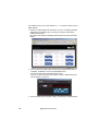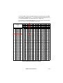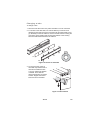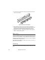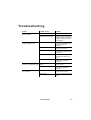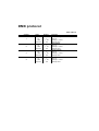
1
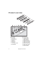
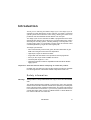
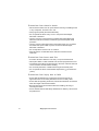
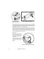
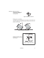
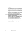
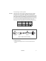
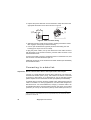
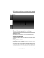
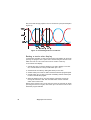
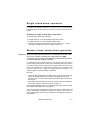
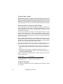
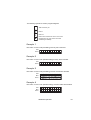
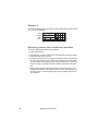
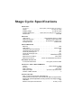
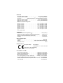
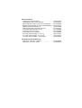
Stage Cyclo
User manual
Dimensions
Measurements are in millimeters
1272
209
135
© 2005 Martin Professional A/S, Denmark.
All rights reserved. No part of this manual may be reproduced, in any form or by any means,
without permission in writing from Martin Professional A/S, Denmark.
Printed in Denmark.
P/N 35000167, Rev. B
Contents
Product overview . . . . . . . . . . . . . . . . . . . . . . . . . . . . . . . . . . . . . 4
Introduction . . . . . . . . . . . . . . . . . . . . . . . . . . . . . . . . . . . . . . . . . 5
Safety information . . . . . . . . . . . . . . . . . . . . . . . . . . . . . . . . . . . 5
Installation . . . . . . . . . . . . . . . . . . . . . . . . . . . . . . . . . . . . . . . . . . 7
Mounting . . . . . . . . . . . . . . . . . . . . . . . . . . . . . . . . . . . . . . . . . . 7
AC power. . . . . . . . . . . . . . . . . . . . . . . . . . . . . . . . . . . . . . . . . 10
Connecting to a data link . . . . . . . . . . . . . . . . . . . . . . . . . . . . . 12
Burning in fluorescent tubes . . . . . . . . . . . . . . . . . . . . . . . . . . 13
Ambient temperature . . . . . . . . . . . . . . . . . . . . . . . . . . . . . . . . 13
Stand-alone operation . . . . . . . . . . . . . . . . . . . . . . . . . . . . . . . . 14
DIP-switch settings in stand-alone mode . . . . . . . . . . . . . . . . 15
Stand-alone operation settings . . . . . . . . . . . . . . . . . . . . . . . . 15
Single stand-alone operation. . . . . . . . . . . . . . . . . . . . . . . . . . 17
Master/slave stand-alone operation . . . . . . . . . . . . . . . . . . . . 17
DMX-controlled operation . . . . . . . . . . . . . . . . . . . . . . . . . . . . . 21
Setting a DMX control address . . . . . . . . . . . . . . . . . . . . . . . . 21
Service . . . . . . . . . . . . . . . . . . . . . . . . . . . . . . . . . . . . . . . . . . . . 24
Fluorescent tubes . . . . . . . . . . . . . . . . . . . . . . . . . . . . . . . . . . 24
Main fuse . . . . . . . . . . . . . . . . . . . . . . . . . . . . . . . . . . . . . . . . . 26
Cleaning . . . . . . . . . . . . . . . . . . . . . . . . . . . . . . . . . . . . . . . . . 26
Troubleshooting. . . . . . . . . . . . . . . . . . . . . . . . . . . . . . . . . . . . . 27
DMX protocol . . . . . . . . . . . . . . . . . . . . . . . . . . . . . . . . . . . . . . . 28
Stage Cyclo Specifications . . . . . . . . . . . . . . . . . . . . . . . . . . . . 29
Product overview
A
B
C
D
E
F
G
H
I
J
K L
DMX UT
O
5
RJ4 X IN
DM
M N
DMXIN
DMX UT
O
O
DMXIN
FUS
E
5
RJ4X OUT
DM
PUT
S IN
MAIN
Main assembly
Connections panel
A Housing
H AC power input
B Colored tubes
I
DMX in (RJ-45)
C Diffuser
J
DMX out (RJ-45)
D White tube
K DMX out (3-pin XLR)
E Reflector
L DMX in (3-pin XLR)
F Clear plastic cover
M DMX out (5-pin XLR)
G Front frame
N DMX in (5-pin XLR)
O Main fuseholder
4
Stage Cyclo user manual
Introduction
Thank you for selecting the Martin Stage Cyclo. The Stage Cyclo is
designed for wash illumination of sets, features, and artists. A patented
optical system ensures effective color mixing, allowing the fixture to be
positioned close to illuminated surfaces without color hot-spots.
The Stage Cyclo can be controlled via DMX or programmed with a standalone light show (which it can run alone or in a synchronized group). It has a
wide range of mounting options, including stacking to form dynamic colorchanging light walls. Four dimmable T5 high-output fluorescent tubes
combine high efficiency, bright color and long lamp life.
The Stage Cyclo features:
• Full 0-100% intensity control of red, green, blue and white tubes to give
RGB color mixing and fine-tuned color temperature
• High output, long life T5 fluorescent tubes
• Tough steel case with rubber corner protectors and carrying handle
• XLR 3-pin, XLR 5-pin and RJ-45 DMX connectors.
• One-tenth peak angle 107° x 121°
• Optional accessories include an adjustable bracket that allows flexible
rigging options.
Important! Read this manual before attempting to install this product.
Updated user manuals for this and all other Martin products are available
from the Support area of the Martin website at http://www.martin.com.
Safety information
Warning!
This product is for professional use only. It is not for household
use.
This product presents risks of lethal or severe injury due to fire and heat,
electric shock and falls. Read this manual before powering or installing this
fixture, follow the safety precautions listed below, and observe all warnings
in this manual and on the fixture. If you have any questions about how to
operate this fixture safely, contact your Martin dealer or call the Martin 24hour service hotline at +45 70 200 201.
Introduction
5
Protection from electric shock
• Disconnect the fixture from AC power before removing or installing a tube
or any component, and when not in use.
• Always ground (earth) the fixture electrically.
• Do not operate the fixture if any cover or component is damaged,
deformed or defective.
• Use only a source of AC power that complies with local building and
electrical codes and has both overload and ground fault (earth fault)
protection.
• Use only a power cable approved for extra hard usage. Do not operate
the fixture if the power cable or power connections are damaged,
deformed or defective.
• Do not expose the fixture to rain or moisture.
• Refer all service not described in this manual to a Martin service
technician.
Protection from burns and fire
• Provide a minimum clearance of 25 mm (1 inch) around the fixture.
• Never place filters or other materials over the clear polycarbonate cover.
• The exterior of the fixture can become hot to the touch. Allow the fixture to
cool for at least 5 minutes before handling.
• Do not modify the fixture or install other than genuine Martin parts.
• Do not operate the fixture if the ambient temperature (Ta) exceeds 40°C
(104°F).
Protection from injury due to falls
• Ensure that all fasteners and components are secure and use an
approved means of secondary attachment such as a safety cable.
• Ensure that all supporting structures, surfaces and fasteners can bear ten
times the weight of all fixtures installed.
• Block access below the work area whenever installing, servicing or
removing the fixture.
• Secure stacked fixtures with safety attachments so that they cannot fall or
be pushed over.
6
Stage Cyclo user manual
Installation
This section describes in general terms how to install the fixture, connect it
to AC power and connect to a DMX controller. These procedures must be
performed by qualified professionals.
Mounting
The Stage Cyclo features a range of
mounting and stacking options when
used in combination with Martin
Omega clamps.
Warning!
Check that all fasteners,
structures and surfaces used to
mount the Stage Cyclo can bear
at least ten times the total
weight of all devices installed.
A maximum of 8 Stage Cyclos
may be hung vertically using
the Stage Cyclo mounting
bracket and Martin omega
clamps.
Work from a stable platform and
block access below the work
area when installing or
servicing fixtures above headheight.
Max. 8 fixtures
Figure 1: Mounting bracket
Riggin g optio ns
The clamp attachment points on the top, ends and back of the fixture
provide a range of rigging options.
An adjustable mounting bracket is available as an optional accessory (P/N
91611206).
Installation
7
Figure 2: Rigging with a
Martin half-coupler
Figure 2: Safety wire attachment
Ensure that mounting hardware can bear at least ten times the total weight
of the fixtures installed. Using the mounting bracket or Martin half-coupler
(P/N 90602005) and Martin omega clamps (P/N 91602001), a maximum of
eight fixtures may be flown in one connected stack.
Anchor fixtures securely to the supporting structure with safety cables that
can bear at least 10 times the weight of all suspended fixtures. Attach safety
cables to every fixture using the eyebolts on the fixtures’ connections panels
(see Figure 2). Do not use mounting brackets or clamps as attachment
points, as this will leave fixtures unsecured.
Stacking
The quarter-turn clamping
points allow multiple Stage
Cyclos to be clamped together
with omega clamps to form
light walls.
Ensure that stacked fixtures
are secured with a safety
attachment so that they cannot
fall over.
Figure 3: Stacking with omega clamps
8
Stage Cyclo user manual
Important! Make sure that all
quarter-turn fasteners are
turned fully clockwise
until they lock.
Figure 4: Quarter-turn fasteners
Placing on a su rface
The Stage Cyclo can be placed flat or at an angle on a level surface and
used as an uplight. The adjustable support rods allow the fixture to be
placed at various angles.
57°
38°
Figure 5: Placing on a level surface
Release the support rods by
pushing the clips on the ends
of the housing.
Figure 6: Support rod release
Installation
9
AC power
It is the installer’s responsibility to ensure that all local regulations and legal
requirements are observed when installing and powering the Stage Cyclo.
The Stage Cyclo is available in two models, one for 100-130 V, 60 Hz AC
power only, and one for 208-250 V, 50/60 Hz AC power only. Full power
compatibility and consumption data are given in the Specifications section
on page 29.
Many fixed installations use common neutral conductors in branch circuit
distribution boxes. To avoid unintentional tripping of the RCD (ground fault
circuit breaker), ensure that the Stage Cyclo’s neutral conductor is
connected to AC power via the same RCD as the live conductor.
Important! Stage Cyclos contain electronic ballasts that “leak” a total
current of between 0.8mA and 4mA to ground (earth). Make sure
that fixtures are correctly connected to ground (earthed) so that
this “leakage” current can be absorbed.
Because of the “leakage” current, we recommend connecting a
maximum of seven Stage Cyclo fixtures per circuit where each
circuit is protected by a 30mA RCD. This should avoid
unintentional tripping of RCDs. Bear in mind that some RCDs
rated at 30mA may trip when leakage to ground is as low as
20mA.
Depending on the type of installation, electrical regulations in
some countries may permit the use of RCDs with a trip current
rating higher than 30mA. When considering this option, the
installer must ensure that all local safety, building and electrical
regulations are respected.
10
Stage Cyclo user manual
Co nnecting to mains powe r
Warning!
Check that your local AC power voltage matches the voltage
specified on the serial number label before applying power.
The Stage Cyclo is supplied with a Neutrik PowerCon® NAC3FCA power
cable connector that must be installed on a power cable approved for extra
hard usage. The cable connector accepts power cable from 5 mm (0.20 in.)
to 11 mm (0.43 in.) diameter when fitted with a white chuck, or from 9.5 mm
(0.38 in.) to 15 mm (0.59 in.) diameter when fitted with a black chuck.
Some common color-coding systems for AC power wiring are given below:
Wire (EU)
Wire (US)
Pin
Marking
brown
black
live
L
N
blue
white
neutral
yellow/green
green
ground
Table 1: Wiring codes
Housing
Insert
Chuck
Bushing
Figure 7: Cable connector assembly
To install the connector:
1. Assemble the bushing and chuck on your power cable as shown in
Figure 7.
Installation
11
2. Prepare the power cable and use a screwdriver to clamp the wires in the
appropriate terminals in the insert as shown in Figure 8.
20 mm
8 mm
[0.
787”]
N
[0.
315”]
L
Figure 8: Cable connector wiring
3. Slide the insert and chuck into the housing, making sure that the raised
tabs engage in the keyways inside the housing..
4. Use an open-ended wrench (spanner) to fasten the bushing onto the
housing (max. torque: 2.5 Nm /1.8 ft-lbs).
To plug the power cable in, line up the raised tab on the cable connector
with the keyway in the chassis connector, push the cable connector in and
twist clockwise to lock.
To remove the cable connector, pull back the latch to release the lock, twist
the connector counterclockwise and pull out.
Additional connectors can be obtained from Martin dealers (P/N 05342804)
and Neutrik® stockists
Connecting to a data link
Important! Never connect more than 1 data input and 1 data output.
Fixtures on a serial data link must be daisy-chained in one single line,
maximum 500 meters (1640 ft.) long, with maximum 32 fixtures. To exceed
32 fixtures or 500 meters, or to add branches, use an optically isolated
splitter-amplifier such as the Martin RS-485 Opto-Splitter (P/N 90758060).
A reliable data connection requires suitable cable. Standard microphone
cable is unsuitable. For touring applications, use DMX cable designed for
RS-485 devices. For fixed installations, Category 5 network cable is an
acceptable alternative. Recommended minimum wire sizes are 24 AWG
(0.25mm2) for runs up to 300 meters (1000 ft) and 22 AWG (0.32 mm2) for
Content in the line drawings on this and the previous page is copyright ©2003 Neutrik® AG and
used by permission. These illustrations may not be reproduced in any form without the written
permission of Neutrik® AG.
12
Stage Cyclo user manual
longer cable runs. Your Martin Architectural dealer can advise and supply
suitable cable.
The Stage Cyclo has RJ-45 as well as 3-pin and 5-pin XLR sockets for DMX
input and output. To avoid damage to the fixture, use only one input and one
output at the same time.
• XLR connectors are wired pin 1 to shield, pin 2 to cold (-), and pin 3 to hot
(+). There is no connection to pins 4 and 5 on 5-pin XLR connectors.
• RJ-45 connectors are wired pins 7 & 8 to shield, pin 2 to signal - (cold)
and pin 1 to signal + (hot).
Some older fixtures have reversed polarity XLR sockets (pin 2 hot and pin 3
cold). Socket polarity is normally labelled on products and specified in user
manuals. Use a phase-reversing cable between the Stage Cyclo and any
device with reversed XLR connector polarity.
To connect the data link:
1. Connect the DMX data output from the controller to one of the DMX input
sockets of the nearest fixture.
2. Connect one DMX output of this fixture to the DMX input of the next
fixture, and continue connecting output to input.
3. Terminate the link by inserting a male XLR DMX termination plug (P/N
91613017) or RJ-45 DMX termination plug (P/N 91613028) in the data
output of the last fixture.
Burning in fluorescent tubes
For optimum tube life and performance, burn in new fluorescent tubes for
100 hours at full power.
Ambient temperature
Do not operate the Stage Cyclo if ambient temperature (Ta) exceeds 40°C
(104°F).
The Stage Cyclo can be started at full intensity from -20°C (-4°F), but needs
to be at operating temperature for best dimming characteristics. When
operating at extremely low ambient temperatures, start the fixture at full
power and allow it to warm up for approximately 10 minutes before
dimming. If dimming characteristics are impaired when running tubes at low
intensity in extreme cold conditions, the fixture may need to be warmed up
by periodically running tubes at higher intensity.
Installation
13
Stand-alone operation
In stand-alone operation, the Stage Cyclo can be used without a DMX
controller. Static single colors or two-color mixes can be displayed, or
fixtures can be programmed to change colors in cycles. Changes can be
programmed at 1, 5, 10 or 30 second intervals.
Two stand-alone operation modes are available:
• In single stand-alone operation, fixtures run independently of each
other. No data link is required.
• In master/slave stand-alone operation, fixtures must be linked.
Synchronized action in all fixtures is triggered by one “master” fixture.
Programming single and
master/slave stand-alone
operation involves setting the
p i n s o n t h e f i x t u r e ’s D I P
switch. The DIP switch is
protected behind a sliding
cover on the back of the
fixture’s housing. To access
the switch, pull the knob in
the connections panel recess
(see illustration) and slide
open the cover.
Figure 9: Dip switch access
An overview of the DIP switch settings is provided on the next page. A quick
reference table covering DIP switch functions is also provided on the back
cover of this manual.
14
Stage Cyclo user manual
DIP-switch settings in stand-alone mode
Pin
Function
1
White active
2
Red active
3
Green active
4
Blue active
5&6
Program speed
Pin 6
Pin 5
Speed
OFF
OFF
1 sec. steps (fastest setting)
OFF
ON
5 sec. steps
ON
OFF
10 sec. steps
ON
ON
30 sec. steps (slowest setting)
7
OFF = Blackout fading, ON = Crossfading
8
OFF = Run program, ON = Pause program
9
OFF = Master, ON = Slave (Note: do not set more than one fixture as master)
10
ON = Stand-alone mode.
Stand-alone operation settings
Activating colors
DIP switch pins 1 to 4 each activate a color in the stand-alone program.
Setting program speed
Combinations of DIP switch pins 5 and 6 allow one of four different speeds
to be set.
Fading between col ors
If DIP switch 7 is set to OFF (blackout fading), colors fade to almost
blackout before the next color fades in.
If DIP switch 7 is set to ON (crossfading), color fading overlaps. If two or
more colors are active, one color fades in while another is fading out, giving
a color mixing effect. For example, if red and blue are activated and
crossfading is selected, colors will crossfade from red through purple to
Stand-alone operation
15
blue, then back through purple to red in a continuous cycle (see example in
Figure 10).
100%
Red
100% Blue
50% Red
50% Blue
50%
0%
100% Red
Blue
0% Red
0% Blue
Time
Blue
Purple
Red
Figure 10: Crossfading between red and blue
Setting a static color display
In stand-alone operation, a static (non-changing) color display can be set by
pausing the program at the point where it is showing the desired color.
Either one color or a mix of two colors can be “frozen” in this way.
To set a static color display:
1. Activate the color you wish to display (if you wish to display a two-color
mix, activate these two colors) on DIP switch pins 1 to 4.
2. Set the fixture as master by setting DIP switch pin 9 to OFF.
3. Set DIP switch pins 5 and 6 to ON to activate the slowest program speed.
4. Set DIP switch pin 7 to OFF to activate crossfading and DIP switch pin 8
to OFF to activate the program.
5. When the desired color or color mix appears, pause the program by
moving DIP switch 8 to ON. This color will remain “frozen” until DIP
switch 8 is moved to OFF.
Note that the paused color is lost when the fixture is powered off. When
powering the fixture on again, DIP switch pin 8 must be moved to OFF
before the program will start.
16
Stage Cyclo user manual
Single stand-alone operation
In single stand-alone operation, a fixture runs its own program
independently of all other fixtures. To do this, the fixture must be set as a
master.
Activating single stand-al one operation
To activate single stand-alone operation:
1. Set DIP switch pin 10 to ON (activates stand-alone mode).
2. Set DIP switch pin 9 to OFF (activates master mode).
3. Apply power and program the fixture using DIP switch pins 1 - 8 (see
“DIP-switch settings in stand-alone mode” on page 15).
Master/slave stand-alone operation
Important! Do not set more than one fixture on a data link as master, and
do not set a fixture as master on a data link with a DMX
controller. Doing so may cause damage to the electronics that is
not covered by the product warranty.
In master/slave stand-alone operation, one master fixture transmits a
synchronizing signal to slave fixtures over the data link each time it starts a
new action. Slave fixtures start their next programmed action when they
receive this signal from the master fixture. Programs can be identical on all
fixtures, or fixtures can – subject to certain practical constraints – run
programs that are synchronized but not identical.
Note that:
• Colors are always displayed in the order: white, red, green then blue. This
means for example that if red is activated, it will always be first in the
program. If red is not activated but green is activated, green will be first in
the program.
• Each fixture follows the program set on its own DIP switch as described in
“DIP-switch settings in stand-alone mode” on page 15.
More sophisticated light shows can be programmed using a DMX controller
(see “DMX-controlled operation” on page 21).
The synchronization signal used by Stage Cyclo fixtures is identical to that
used in other DMX-controllable Cyclo fixtures with the same number of
tubes, allowing these products to be combined in master/slave operation on
one data link.
Stand-alone operation
17
Identical light shows
Master and slave fixtures can be set to behave identically. In this mode, the
master sends synchronizing signals to the slaves, and all fixtures run the
same light show. Each slave fixture follows the program set on its own DIP
switch, so for identical operation, all fixtures’ DIP switch settings must be the
same apart from pin 9, which is set to ON for slaves and OFF for the master.
Synchronized non- identical light shows
It is also possible to synchronize changes but program slave fixtures to
behave differently from the master. To use this feature effectively, you need
to plan your light show using scenes as building blocks and set the fixtures’
DIP switches accordingly.
A scene is a change from one output to another. When a fixture is in slave
mode, it starts a scene when it receives a synchronization signal from the
master. The time taken by the scene is determined by the speed setting of
the DIP switch. A slave will not respond to new synchronization signals until
its scene is complete.
When crossfading is selected, each color takes up one scene (fade in only).
When blackout fading is selected, each color takes up two scenes (fade in
and fade out). This means that a maximum of 8 scenes can be programmed
with all 4 tubes activated and blackout fading selected.
Each time the master fixture starts at scene 1, it sends a signal to all the
slave fixtures to start at scene 1. This means that if a slave fixture has:
1. Fewer scenes than the master fixture, it will run these in a cycle until the
master fixture signals that the program should start from the beginning
again.
2. More scenes than the master, the additional scenes will never run,
because the program will reset to the first scene when the master starts
its program from the beginning.
Here is an example of what will happen if a slave fixture has fewer scenes
than the master fixture:
Fixture setting
Scene pattern
Master with 6 scenes
123456 123456 123456 ...
Slave with 4 scenes
123412 123412 123412 ...
Program examples
The following examples show how an individual fixture’s program is made
up of scenes.
18
Stage Cyclo user manual
The following symbols are used in program diagrams:
Tube turned fully off
Fade in
Fade out
Fade to 50% and back to 100% in one scene
(applies when only one color is active and
crossfading is selected)
Example 1
DIP switch 7 is set to ON (crossfading) and only red is activated:
Red
Scene
1
1
1
1
1
1
1
1
1
1
1
1
Example 2
DIP switch 7 is set to OFF (blackout fading) and only red is activated:
Red
Scene
1
2
1
2
1
2
1
2
1
2
1
2
Example 3
DIP switch 7 is set to ON (crossfading) and red and blue are activated:
Red
Blue
Scene
1
2
1
2
1
2
1
2
1
2
1
2
Example 4
DIP switch 7 is set to OFF (blackout fading) and red and blue are activated:
Red
Blue
Scene
1
2
3
4
1
2
3
Stand-alone operation
4
1
2
3
4
19
Example 5
To achieve a rainbow effect, activate red, green and blue and set DIP switch
pin 7 to ON (crossfading).
Red
Green
Blue
Scene
1
2
3
1
2
3
1
2
3
1
2
3
Activating master/slave stand- alone operation
To activate master/slave stand-alone operation:
1. Power all fixtures off.
2. Set all fixtures as slaves and put them into stand-alone mode by setting
DIP switch pins 9 and 10 to ON.
3. Decide which fixture to use as master and set this fixture’s DIP switch pin
9 to OFF. Note that any fixture can be set as master, but you will obtain
the most reliable data signal by either setting the first fixture on the link as
master or using RJ-45 DMX termination plugs at both ends of the data
link.
4. When power is applied, slave fixtures will go to the next scene in their
program each time the master goes to its next scene. Slave fixtures will
also start scene 1 of their programs each time the master starts scene 1
of its program.
20
Stage Cyclo user manual
DMX-controlled operation
The Stage Cyclo may be operated with any USITT DMX (1990) lighting
control device. The fluorescent tubes can be dimmed from maximum output
right down to zero using four channels on a DMX controller. This allows a
wide range of color shades with almost infinitely variable intensity to be
obtained using additive color mixing. The color temperature of white light
can be fine-tuned by running the white tube at high power and adding blue
or red at low power. Replacement white tubes with various color
temperatures are available (see “Accessories” on page 31).
The four DMX channels are used to control the tubes as follows:
• First channel: white
• Third channel: green
• Second channel: red
• Fourth channel: blue
Setting a DMX control address
The DMX address, also known as the start channel, is the first of the four
DMX control channels used. It must be set on the fixture’s DIP switch before
the controller can send commands to the fixture. The Stage Cyclo responds
to commands sent to the DMX address and the next three channels. For
example, if the DMX address is set to 100, the Stage Cyclo uses channels
100, 101, 102 and 103.
Allow enough channels when setting the DMX address. If control channels
for two fixtures overlap, one of the fixtures will receive the wrong
commands.
If two or more Stage Cyclos
share the same DMX address,
they will receive the same
commands and respond
identically. Individual control
will be impossible.
To access the fixture’s DIP
switch, slide the hatch open
by pulling on the pin in the
connections panel recess (see
Figure 11)
Figure 11: DIP switch access
DMX-controlled operation
21
The default factory-set control address is ‘1’. To reset the Stage Cyclo’s
DMX address:
1. Decide on a DMX address for the fixture. If you are calculating the DMX
addresses for multiple fixtures, save time by using the online Martin
Address Calculator at
http://www.martin.dk/service/utilities/AddrCalc/index.asp (see illustration
below).
2. You can also look up DIP-switch settings using the Martin DIP Switch
Calculator, available for use and downloadable free at
http://www.martin.dk/service/dipswitchpopup.htm
If you do not have Internet access, refer to "Table 2: DMX address DIPswitch settings" on page 23.
3. Set DIP switch pins 1 through 9 to ON (1) or OFF (0) to set the address.
22
Stage Cyclo user manual
To use this table, first find the DMX address in the main block in the table.
Then read the settings for pins 1 - 5 to the left and read the settings for pins
6 - 9 above the address. “0” means OFF and “1” means ON.
For example, to set the DMX address to 101, you need to set DIP-switch
pins 1, 3, 6 and 7 to ON, as highlighted in the table.
DIP switch pins setting
0 = OFF
1 = ON
#1
0
1
0
1
0
1
0
1
0
1
0
1
0
1
0
1
0
1
0
1
0
1
0
1
0
1
0
1
0
1
0
1
#2
0
0
1
1
0
0
1
1
0
0
1
1
0
0
1
1
0
0
1
1
0
0
1
1
0
0
1
1
0
0
1
1
#3
0
0
0
0
1
1
1
1
0
0
0
0
1
1
1
1
0
0
0
0
1
1
1
1
0
0
0
0
1
1
1
1
#4
0
0
0
0
0
0
0
0
1
1
1
1
1
1
1
1
0
0
0
0
0
0
0
0
1
1
1
1
1
1
1
1
#5
0
0
0
0
0
0
0
0
0
0
0
0
0
0
0
0
1
1
1
1
1
1
1
1
1
1
1
1
1
1
1
1
#9
#8
#7
#6
0
0
0
0
0
0
0
1
0
0
1
0
0
0
1
1
0
1
0
0
0
1
0
1
0
1
1
0
0
1
1
1
1
0
0
0
1
0
0
1
1
0
1
0
1
0
1
1
1
1
0
0
1
1
0
1
1
1
1
0
1
1
1
1
1
2
3
4
5
6
7
8
9
10
11
12
13
14
15
16
17
18
19
20
21
22
23
24
25
26
27
28
29
30
31
32
33
34
35
36
37
38
39
40
41
42
43
44
45
46
47
48
49
50
51
52
53
54
55
56
57
58
59
60
61
62
63
64
65
66
67
68
69
70
71
72
73
74
75
76
77
78
79
80
81
82
83
84
85
86
87
88
89
90
91
92
93
94
95
96
97
98
99
100
101
102
103
104
105
106
107
108
109
110
111
112
113
114
115
116
117
118
119
120
121
122
123
124
125
126
127
128
129
130
131
132
133
134
135
136
137
138
139
140
141
142
143
144
145
146
147
148
149
150
151
152
153
154
155
156
157
158
159
160
161
162
163
164
165
166
167
168
169
170
171
172
173
174
175
176
177
178
179
180
181
182
183
184
185
186
187
188
189
190
191
192
193
194
195
196
197
198
199
200
201
202
203
204
205
206
207
208
209
210
211
212
213
214
215
216
217
218
219
220
221
222
223
224
225
226
227
228
229
230
231
232
233
234
235
236
237
238
239
240
241
242
243
244
245
246
247
248
249
250
251
252
253
254
255
256
257
258
259
260
261
262
263
264
265
266
267
268
269
270
271
272
273
274
275
276
277
278
279
280
281
282
283
284
285
286
287
288
289
290
291
292
293
294
295
296
297
298
299
300
301
302
303
304
305
306
307
308
309
310
311
312
313
314
315
316
317
318
319
320
321
322
323
324
325
326
327
328
329
330
331
332
333
334
335
336
337
338
339
340
341
342
343
344
345
346
347
348
349
350
351
352
353
354
355
356
357
358
359
360
361
362
363
364
365
366
367
368
369
370
371
372
373
374
375
376
377
378
379
380
381
382
383
384
385
386
387
388
389
390
391
392
393
394
395
396
397
398
399
400
401
402
403
404
405
406
407
408
409
410
411
412
413
414
415
416
417
418
419
420
421
422
423
424
425
426
427
428
429
430
431
432
433
434
435
436
437
438
439
440
441
442
443
444
445
446
447
448
449
450
451
452
453
454
455
456
457
458
459
460
461
462
463
464
465
466
467
468
469
470
471
472
473
474
475
476
477
478
479
480
481
482
483
484
485
486
487
488
489
490
491
492
493
494
495
496
497
498
499
500
501
502
503
504
505
506
507
508
509
510
511
Table 2: DMX address DIP-switch settings
DMX-controlled operation
23
Service
With long-life fluorescent tubes and virtually no moving parts, the Stage
Cyclo is almost service-free.
Fluorescent tubes
The Osram high output T5 tubes fitted as standard meet color specifications
for at least 10 000 hours, after which color intensity may gradually fall.
Average tube life is 20 000 hours, but note that tube life will vary depending
on operating conditions.
Tub e positio ns
Tube positions in the Stage Cyclo are identified as shown below:
Marking in
fixture
Marking on
tube
R
OSRAM FQ
54W/60 RED
G
OSRAM FQ
54W/66 GREEN
B
OSRAM FQ
54W/67 BLUE
Reference illustration
B G
R
No marking. Tube OSRAM FQ
54W/860 Daylight
located above
diffuser.
The burning positions of fluorescent tubes affect their warm-up times,
operating temperature, light output and tube life. For best results:
• Install tubes so that the manufacturer’s markings are all at the same end
of the fixture.
• If the fixture is mounted in a vertical position or at an angle from the
horizontal, place the ends of the tubes that carry the manufacturer’s
markings at the lower end of the fixture (in a cold environment, i.e. where
temperatures are generally around or below freezing point, locate the
markings at the upper end of the fixture).
24
Stage Cyclo user manual
Chan ging a tube
To change a tube:
1. Disconnect the fixture from AC power and allow to cool for 5 minutes.
2. For access to the white tube, use a 3mm Allen key to remove the 8
retaining screws and remove the front frame (G) and clear plastic cover
(F). Be ready to catch the reflector, as this is a loose fit in the housing, but
note that a ground (earth) lead connects the reflector to the housing.
Disconnect this lead and remove the reflector.
3mm
F
G
Figure 12: Access to white tube
3. To remove a tube, press on
the metal caps at both ends of
the tube and rotate the tube
1/4 turn in whichever direction
is easiest. Then slide the
tube’s terminal pins out of their
sockets. Support the tube at
both ends as it is released.
Figure 13: Tube removal
Service
25
4. For access to the colored tubes, remove the eight Pozidriv PZ2 screws
and remove the diffuser.
Figure 14: Access to colored tubes
5. When installing new tubes, line them up so that the manufacturer’s
markings on all tubes are at the same end of the fixture. Slide the tube’s
terminal pins fully into their sockets and rotate the tube 1/4 turn to
engage the pins. Check that the tube is held securely in the sockets.
6. Replace all components – remembering to attach the earth strap to the
reflector – before reapplying power.
Main fuse
The main fuseholder is located in the connections panel recess (see
“Product overview” on page 4´). Using a flat-head screwdriver, turn the
fuseholder cover approximately 1/8 turn to release the cover and main fuse.
Isolate the fixture from power and make sure power cannot be reapplied
accidentally before changing the fuse.
Never replace a fuse with one of a different type or rating. See “Power” on
page 30 for main fuse details.
Cleaning
Turn off power to the fixture before cleaning, and use a damp cloth to wipe
clean.
26
Stage Cyclo user manual
Troubleshooting
Problem
Probable cause(s)
Remedy
No response from fixture when No power to fixture.
Check power connections.
power is applied.
Ground fault protection circuit Reset RCD. If problem
breaker (RCD) has tripped.
persists, have an electrician
replace the RCD or reduce the
number of fixtures powered
via one RCD.
Fixture does not respond
correctly to DMX control.
Controller not connected.
Check DMX data link. Inspect
connections and test cables.
Repair or replace as
necessary.
Incorrect DMX addressing.
Check address setting on
fixture and controller.
Data link not terminated.
Insert DMX termination plug in
unused socket of last fixture
on data link.
Fixture on link set as master.
Check that all fixtures are set
as slaves (DIP switch pin 9
ON).
Defective fixture.
Bypass fixtures one at a time
until normal operation is
regained.
Fixtures do not behave
Two fixtures operating as
correctly in master/slave mode masters.
Defective fixture.
Poor quality light output and/or Tube or tubes not burnt in.
color rendering.
Tube defective.
Troubleshooting
Check that only one fixture is
set as master.
Bypass fixtures one at a time
until normal operation is
regained.
Run fixture for at least 100
hours to burn in tubes.
Disconnect fixture and replace
tube.
27
DMX protocol
Start code = 0
Channel
1
2
3
4
Value
Percent
Function
0-2
3-252
253-255
0
1 - 99
100
White intensity
Tube off
Intensity 1→100%
Intensity 100%
0-2
3-252
253-255
0
1 - 99
100
Red intensity
Tube off
Intensity 1→100%
Intensity 100%
0-2
3-252
253-255
0
1 - 99
100
Green intensity
Tube off
Intensity 1→100%
Intensity 100%
0-2
3-252
253-255
0
1 - 99
100
Blue intensity
Tube off
Intensity 1→100%
Intensity 100%
Stage Cyclo Specifications
PHYSICAL
L x W x H . . . . . . . . . . . . . . . . .1272 x 209 x 135 mm (50 x 8.2 x 5.3 in.)
Weight . . . . . . . . . . . . . . . . . . . . . . . . . . . . . . . . . . . . . 10.5 kg (23.1 lbs)
Shipping weight . . . . . . . . . . . . . . . . . . . . . . . . . . . . . . 11.5 kg (25.3 lbs)
Shipping dimensions . . . . . . . . 1300 x 350 x 210 mm (52 x 14 x 8,4 in.)
Fixture color. . . . . . . . . . . . . . . . . . . . . . . . . . . . . . . . . . . . . . . Gunmetal
SOURCE
Light source . . . . . . . . . . . . . . . . . . . . . . T5 fluorescent tubes (4 x 54W)
Approved lamp type. . . . . . . . . . . . . . . . . . OSRAM T5 high output 54W
Color authenticity . . . . . . . . . . . . . . . . . . . Guaranteed to 10 000 hours
Average tube life . . . . . . . . . . . . . . . . . . . . . . . . . . . . . . . . 20 000 hours
PHOTOMETRICS
Efficiency . . . . . . . . . . . . . . . . . . . . . . . . . . . . . . . . . . . . . . . . . . . . . 28%
Total Output . . . . . . . . . . . . . . . . . . . . . . . . . . . . . . . . . . . 3976 lumens
Half peak angle C0 (horizontal) . . . . . . . . . . . . . . . . . . . . . . . . . . . . . 95°
Half peak angle C90 (vertical) . . . . . . . . . . . . . . . . . . . . . . . . . . . . . . 83°
One-tenth peak angle C0 . . . . . . . . . . . . . . . . . . . . . . . . . . . . . . . . 107°
One-tenth peak angle C90 . . . . . . . . . . . . . . . . . . . . . . . . . . . . . . . 121°
Illuminance . . . . . . . . . . . . . . . . . . . . . . . . . . . . . . . 2066/distance2 [lux]
Measurement conditions . . . . . . . . . . . . . . . . . . . . . . . . . . . 230V, 50Hz
Measurement source. . . . . . . . . . . Osram T5 FQ54W/840+/60+/66+/67
DYNAMIC EFFECTS
0-100% dimmable tubes . . . . . . . . . . . . . . . Red, green, blue and white
CONTROL AND PROGRAMMING
Control . . . . . . . . . . . . . . . . . . . . . . . . . . . . . . . USITT DMX512 (1990)
Receiver . . . . . . . . . . . . . . . . . . . . . . . . . . . . . . . . . . . . . . . . . . .RS-485
DMX addressing . . . . . . . . . . . . . . . . . . . . . . . . . . . . . . . . . . DIP switch
Data input/ output . . . . . . . . . . . . . . . . . . . . 3-pin and 5-pin XLR, RJ-45
Number of DMX channels . . . . . . . . . . . . . . . . . . . . . . . . . . . . . . . . . . 4
INSTALLATION
Floor or surface mounting with adjustable legs
Stacking/side-by-side/end-to-end: lockable with Martin omega brackets
Rigging with optional adjustable mounting bracket and omega brackets
Orientation . . . . . . . . . . . . . . . . . . . . . . . . . . . . . . . . . . . . . . . . . . . . .Any
Minimum free space around fixture . . . . . . . . . . . . . . . . 25 mm (1 inch)
POWER
AC power, 230 V model. . . . . . . . . . . . . . . . . . . . 198 - 250 V, 50/60 Hz
AC power, 110 V model . . . . . . . . . . . . . . . . . . . . . . . 100 - 120 V, 60 Hz
AC input. . . . . . . . . . . .Neutrik PowerCon® (A-type) lockable connector
Main fuse, 230 V model. . . . . . . . . . . . . . . . . . . . . 2 AT (P/N 05020009)
Main fuse, 110 V model . . . . . . . . . . . . . . . . . . . 2.5 AT (P/N 05020010)
Maximum current and power
@ 100 V, 60 Hz . . . . . . . . . . . . . . . . . . . . . . . . .
@ 120 V, 60 Hz . . . . . . . . . . . . . . . . . . . . . . . . .
@ 208 V, 60 Hz . . . . . . . . . . . . . . . . . . . . . . . . .
@ 230 V, 50 Hz . . . . . . . . . . . . . . . . . . . . . . . . .
@ 240 V, 50 Hz . . . . . . . . . . . . . . . . . . . . . . . . .
@ 250 V, 50 Hz . . . . . . . . . . . . . . . . . . . . . . . . .
2.2 A, 218 W, PF 0.998
2.0 A, 235 W, PF 0.999
1.2 A, 235 W, PF 0.993
1.1 A, 234 W, PF 0.988
1.0 A, 233 W, PF 0.986
1.0 A, 231 W, PF 0.983
PF = power factor
THERMAL
Maximum ambient temperature (Ta) . . . . . . . . . . . . . . . . . 40°C (104°F)
Minimum ambient temperature (started at full power) . . . . . -20°C (-4°F)
Maximum total heat dissipation (calculated) . . . . . . . . . . . . 737 BTU/hr.
Cooling . . . . . . . . . . . . . . . . . . . . . . . . . . . . . . . . . . . . . . . . . Convection
CONSTRUCTION
Housing . . . . . . . . . . . . . . . . . . . . . . . . . . . . . . . . . . . . . . . . . Mild steel
Optics . . . . . . . . . . . . . . . . . . . . . . . . . . High specular 99.9% aluminum
Protection factor . . . . . . . . . . . . . . . . . . . . . . . . . . . . . . . . . . . . . . . IP20
APPROVALS
European safety:
EN 60598-1
EN 60598-2-17 + Corr + A2-1997
CSA C22.2, NO 166 pending
ANSI/UL 1573 pending
INCLUDED ITEMS
Red T5 high output tube . . . . . . . . . . . . . . . . . . OSRAM T5 FQ 54W/60
Green T5 high output tube. . . . . . . . . . . . . . . . . OSRAM T5 FQ 54W/66
Blue T5 high output tube . . . . . . . . . . . . . . . . . . OSRAM T5 FQ 54W/67
Cool white (4000 K) T5 high output tube . . . . OSRAM T5 FQ 54W/840
2 x omega brackets incl. 1/4 turn fasteners. . . . . . . . 2 x P/N 91602001
Neutrik PowerCon® NAC3FCA power cable connector . P/N 05342804
User manual . . . . . . . . . . . . . . . . . . . . . . . . . . . . . . . . . . P/N 35000167
ACCESSORIES
Stage Cyclo mounting bracket. . . . . . . . . . . . . . . . . . . . .
Omega bracket with 1/4 turn fasteners . . . . . . . . . . . . . .
Warm white tube (2700 K, Osram T5 FQ 54W/827) . . . .
Daylight white tube (6000 K, Osram T5 FQ 54W/860) . .
DMX link termination plug RJ-45 . . . . . . . . . . . . . . . . . .
DMX link termination plug male XLR 3-pin . . . . . . . . . . .
RJ-45 patch cable (250 mm/ 9.8 in.) . . . . . . . . . . . . . . .
XLR male to RJ-45 converter . . . . . . . . . . . . . . . . . . . . .
XLR female to RJ-45 connector . . . . . . . . . . . . . . . . . . .
50 x CAT5 network cables - 2 m (6.5 ft) . . . . . . . . . . . . .
30 x CAT5 network cables - 5 m (16.4 ft) . . . . . . . . . . . .
15 x CAT5 network cables - 10 m (32.8 ft) . . . . . . . . . . .
P/N 91611206
P/N 91602001
P/N 97020009
P/N 97020011
P/N 91613028
P/N 91613017
P/N 11840088
P/N 11840087
P/N 11840086
P/N 91611044
P/N 91611045
P/N 91611046
ORDERING INFORMATION
Stage Cyclo, 208-250 V, 50/60 Hz. . . . . . . . . . . . . . . . . . P/N 90350000
Stage Cyclo, 100-130 V, 60 Hz . . . . . . . . . . . . . . . . . . . . P/N 90350100
8. ON = Pause
OFF = Play
9. ON = Slave or DMX
OFF = Master
3. Green
2. Red
10. ON = Stand-alone
OFF = DMX
ON
1. White
1 2 3 4 5 6 7 8 910
4. Blue
7. ON = Crossfading
OFF = Blackout fading
5/6. Program speed
Quick reference
Stage Cyclo DIP switch settings
Martin Professional A/S - Olof Palmes Allé 18 - DK-8200 Aarhus N - Denmark
Phone: +45 87 40 00 00 Internet: www.martin.com