1
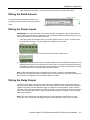
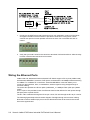
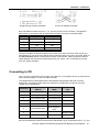
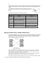
Korenix JetNet 3705 Series Industrial Power over Ethernet Switch User’s Manual Second Edition, Feb, 2007 www.korenix.com Korenix JetNet 3705 Series Industrial Power over Ethernet Switch User’s Manual Copyright Notice Copyright © 2007 Korenix Technology Co., Ltd. All rights reserved. Reproduction in any form or by any means without permission is prohibited. Table of Contents Chapter 1 Introduction .............................................................................................1-1 Overview........................................................................................................... 1-2 Ethernet Switching Technology ........................................................................ 1-2 Power over Ethernet Technology...........................................................1-4 Product Features .............................................................................................. 1-5 Package Checklist ............................................................................................ 1-5 Chapter 2 Hardware Installation ..............................................................................2-1 Introduction....................................................................................................... 2-2 Dimension of JetNet 3705 and 3705f series .............................................2-2 Panel Layout .............................................................................................2-3 LED Indicators..........................................................................................2-4 DIP Switch ................................................................................................2-4 Wiring the Earth Ground................................................................................... 2-5 Wiring the Power Inputs ................................................................................... 2-5 Wiring the Relay Output ................................................................................... 2-5 Wiring the Ethernet Ports ................................................................................. 2-6 Connecting to PD ............................................................................................. 2-7 Wiring the Fiber Ports ( JetNet 3705f series) ................................................... 2-8 DIN-Rail Mounting Installation .......................................................................... 2-9 Chapter 3 Troubleshooting ......................................................................................3-1 Power Connections .......................................................................................... 3-1 Incorrect Connections....................................................................................... 3-1 Faulty or Loosen Cables ...........................................................................3-1 Non-standard Cables.................................................................................3-1 Improper Network Design ........................................................................3-2 LED Indicators .................................................................................................. 3-2 Appendix A Specifications......................................................................................... A-1 Appendix B Revision History..................................................................................... B-1 1 Chapter 1 Introduction Korenix JetNet 3705 Series is a power over Ethernet rail switch that is specially designed for industrial or commercial applications. The following topics are covered in this chapter: Overview Ethernet Switching Technology Power over Ethernet Technology Product Features Package Checklist Installation Guide Overview JetNet 3705 Industrial Power Over Ethernet (PoE) Switches have four ports 10/100 TX ports with PoE injector plus one 10/100TX up-link port( JetNet 3705 ) or four ports 10/100 TX ports with PoE injector plus one 100FX up-link port (multi-mode “-m” or single-mode “-s” models, JetNet 3705f ). It is designed to operate under harsh environmental conditions. The switches provide Power over Ethernet functions to deliver 15.4Watts power budget to powered device (PD), which is in compliance with IEEE802.3af standard to deliver both of Ethernet data and DC 48V power through the traditional UTP or STP cable to the PD. The IP30-design aluminum case further strengthens JetNet 3705 's withstand ability in harsh industrial environments. The event warning is notified to field engineers by relay output triggering field alert system. JetNet 3705 Series Industrial PoE Switch has passed CE/ FCC/ UL safety certifications to help ensure safe and reliable data transmission for industrial applications. JetNet 3705 Series will be your best option for industrial network or security system. Ethernet Switching Technology To better understand the operation of an Ethernet switch, we need to first differentiate it from a hub. An Ethernet hub (or repeater) is a device that is used to simply connect Ethernet nodes. Any message at one hub port is repeated on all ports. That is, hubs forward data packets they receive from a single station to all hub ports. As a result, all port devices connected to a single hub will share the same bandwidth. Then as nodes are added to the network hub, they compete for this finite amount of bandwidth and this can cause data collisions to occur, making network determinism impossible to attain, especially on busy networks. Now determinism is a term that is used to describe the ability to guarantee that a packet is sent or received in a finite and predictable amount of time. The inherent lack of determinism is the main reason that traditional Ethernet had problems being accepted for use in critical control applications, as most control systems have a defined time requirement for packet transmission, typically less than 100ms. 1-2 Korenix JetNet 3705 Series Industrial PoE Switch User’s Manual Introduction Switches on the other hand, are intelligent devices used to more efficiently connect distributed Ethernet nodes than a hub. Unlike a simple hub, a switch provides targeted data transfer, as it will forward a data packet to a specific port or network segment, rather than to all ports, thus freeing up bandwidth. The ability to target a packet to a specific port increases network throughput and helps to eliminate the collisions that have historically made Ethernet non-deterministic. So we see that by targeting the data transfer between ports, switches act as intelligent repeaters to increase network distances. In doing this, they actually split networks into separate collision domains at each port. Thus, switches increase determinism by reducing collisions. Switches also increase network bandwidth and throughput, as well as provide supplemental error checking on data packets to help ensure the integrity of forwarded data. Each port of this switch functions just like any other Ethernet device. It is able to receive and decode Ethernet frames, test for frame integrity, plus assemble and transmit Ethernet frames. With Ethernet, any device can try to send a data frame out at any time. If two devices happen to send a data frame at the same time, then a collision may occur. The arbitration protocol for carrier transmission access of the Ethernet network is called Carrier Sense Multiple Access with Collision Detect (CSMA/CD). With CSMA/CD, each device will first sense whether the line is idle and available for use. If it is, the device will begin to transmit its first frame. If another device also tries to send a frame at the same time, then a collision occurs and both frames are discarded. Each device then waits a random amount of time and retries its transmission until it is successfully sent. Unlike other Ethernet devices, such as an Ethernet host adapter or Network Interface Card (NIC), the port of a switch does not require its own MAC address. During retransmission of a received packet, the switch port will instead look like the originating device by having assumed its source address. This is why the Ethernet collision domain is said to terminate at the switch port. That is, a two-port switch will effectively break a network into two distinct data links or segments. The JetNet 3705 and JetNet 3705f Industrial Ethernet Switch can break a network into 5 distinct data links or segments (also called collision domains). Since all Ethernet nodes are able to recognize the occurrence of a collision, and since the detection of a collision is principal to the way Ethernet arbitrates media access, large domains containing many nodes can become quite cumbersome. Thus, using an Ethernet switch to subdivide a large network into separate collision domains will certainly help to increase throughput. The current tendency in critical industrial control applications is to connect one Ethernet device per switch port. This will produce the most deterministic mode of operation as the switch can then operate full-duplex, with no chance of collisions. This ensures determinism, helping critical control applications to remain predictable and on-time. Each port of a switch forwards data to another port based on the MAC address contained in the received data packet/frame. In order to know which port to forward a data packet to, the switch will learn and store the MAC addresses of every device it is connected to, along with the associated port number. However, until the switch actually learns the port a particular address resides at (the first packet), it forwards this traffic to all ports just like a hub. The switch will use its internal look-up table to quickly determine the location (port) of a node, establish a temporary connection between itself and the node, then terminate the connection once a packet is transferred. In this way, it increases network bandwidth and provides the network determinism required for critical control applications. JetNet 3705 and JetNet 3705f Series Industrial Power over Ethernet Switch uses a store and forward algorithm to process Ethernet frames. That is, it first stores the Ethernet frame and examines it for errors before forwarding it to its destination. Although this method may seem to increase the forwarding time (latency) and possibly cause fragmentation, it effectively reduces the occurrence of error frames and improves overall throughput. This is particularly useful when there is heavy network traffic and or greater potential for noise and interference. Korenix JetNet 3705 Series Industrial PoE Switch User’s Manual 1-3 The industry-wide shift from Ethernet hubs to Ethernet switches has dramatically boosted the bandwidth of networks and helped to eliminate congestion problems inherent with the CSMA/CD protocol (Carrier Sense Multiple Access with Collision Detection). Since a switch operates by learning the location of addresses and forwarding messages directly, unnecessary traffic is greatly reduced. It will use auto-negotiation to regulate the speed and duplex of each port based on the capabilities of connected devices. These features combine with flow control allow a 100M node to effectively communicate with a 10M node without losing data. Connecting one device per switch port also allows two-way, simultaneous transmission to occur (full duplex), essentially doubling the bandwidth. Further, by segmenting a collision domain in this way, the need for non-deterministic carrier sensing (CSMA/CD) is eliminated. The utilization of a store-and-forward switching algorithm allows each packet to be inspected, and corrupt or redundant data to be filtered, further eliminating unnecessary traffic that often slows a network down. Power over Ethernet Technology Power over Ethernet is a revolutionary technology that allows IP telephones, wireless LAN Access Points, Security network Cameras and other IP-based terminals to receive power and data in parallel. The Power over Ethernet can bring a lot of benefits, such as cost saving, simplicity, reliability, safety, control and security. The IEEE802.3af (Power over Ethernet) is established on June 2003, which defined how to deliver DC 48V power and Ethernet frame through the traditional cabling system. PoE architecture includes 2 elements, Power Sourcing Equipment (PSE) and Powered Device (PD), PSE device provides auto detection capability to recognize the characteristics of link partner to deliver exactly power to the PD, it also will not damage the link partner if it is not a PD or the link cable is short, or the device is broken, and execute a series of standard procedure when the PD is disconnected to avoid send out a huge power to damage the device or user. The IEEE802.3af standards have specified the architecture and the type of PSE, PSE supports 2 different types, End-point and Mid-Spain for the different power feeding model and wiring. In the IEEE803.3af also specified the PD should compatible with End-point and Mid-Spain PSE, and exactly, honestly claims the level of power consumption. JetNet 3705 equips 4 PoE injector switch ports, with each port delivering power up to 15.4 watts in maximum, and one 10/100Base TX Up-link port transferring data to remote end. The JetNet 3705 conforms to IEEE 802.3af Power over Ethernet (PoE) standard. Using an external 48VDC power supply, JetNet 3705 enables power and data transmission to be pumped out over the same UTP or STP cable in the four PoE ports. JetNet3705 is in compliance with IEEE 802.3af standard and supports Power Sourcing Equipment (PSE) function. It delivers power through the spare pairs (4, 5, 7, 8) of standard Ethernet CAT-5 cable and transmits data through the traditional pairs (1, 2, 3, 6). The JetNet3705 PoE ports provide PoE auto detection of the link partner to deliver the exact power to the PD. If the link partner is not a PD or the link cable is short, or the device is broken, it will executes a series of standard procedures to avoid sending out a huge power to damage the linked device. 1-4 Korenix JetNet 3705 Series Industrial PoE Switch User’s Manual Introduction Product Features Korenix JetNet 3705 and JetNet3705f Series products have the following features: 4-port 10/100TX with PoE injector plus one 100Mbps fiber up-link port (JetNet3705) 4-port 10/10TX with PoE injector plus one 10/100TX up-link port (JetNet3705f) Support single mode fiber or multi-mode fiber (JetNet3705f) Deliver 15.4W power budget per PoE port Redundant DC Power Inputs Alarm Relay to signal port break and/or power failure Support IEEE 802.3 10Base-T, 802.3u 100Base-TX, 802.3u 100Base-FX (JetNet3705f) 512kbits embedded memory buffer with 1K entry MAC address table auto MDI/MDI-X RJ-45 ports Store-and-Forward switching architecture IEEE 802.3x flow control ¾ Flow control on full-duplex mode ¾ Back pressure on half-duplex mode Reverse power polarity protection Robust Aluminum case, IP30 standard DIN-Rail/Wall-mounting/Desktop Installation Package Checklist Korenix JetNet 3705 Series products are shipped with the following items: One industrial PoE switch One DIN-Rail kit Documentation CD Quick Installation Guide (QIG) If any of the above items are missing or damaged, please contact your local sales representative. JetNet3705 or JetNet 3705f DIN Rail Kit Foot CD Korenix JetNet 3705 Series Industrial PoE Switch User’s Manual QIG 1-5 2 Chapter 2 Hardware Installation This chapter includes information of installation and configuration. The following topics are covered in this chapter: Introduction ¾ Dimension ¾ Panel Layout ¾ LED Indicators ¾ DIP Switch Wiring the Power Inputs Wiring the Relay Output Wiring the Ethernet Ports Wiring the Fiber Ports DIN-Rail Mounting Installation Wall-Mounting Installation Introduction Dimension of JetNet 3705 and 3705f series Following is the JetNet3705 series mechanical dimension diagram, the unit is mm. JetNet3705 Dimension JetNet3705F Dimension 2-2 Korenix JetNet 3705 Series Industrial PoE Switch User’s Manual Hardware Installation Panel Layout The following figures includes product view of top side, right side and front side for JetNet3705 and JetNet3705f. Top View On the top side includes diagnostics LEDs for system Power, Fault LED, PoE power forwarding status and port link status. On the right side include DIP Switch, exteranl DC jack for AC/DC power adapter power input. Right Side View The DC jack accept DC 48V without polarity reverse protect function. The DIP switch is for the event relay control for port link and power event. Very easy configuration , just ON/OFF to enable or disable each event trigger. Front Side View The front view figures include JetNet3705 and JetNet3705f. JetNet3705 It includes 4 ports IEEE802.3af PoE Switch port and one RJ-45 connector (JetNet3705) or one 100Mbps Fiber (JetNet3705f) for uplink. The 6-Pins terminal block connector is for DC 48V power input and relay alarm output. It equipped 2 Power inputs with polarity reverse protect function and the input power range from DC 44V to DC 57V. JetNet3705f Relay Alarm Output will triggered by the port or power event and disable/enable by the DIPswitch. If there is any event occurred, the relay output will be formed as a close circuit. The ability of relay is DC24V/1A. To ensure the system working in a reliable status,please make sure it have make exactly grounding with Earth Ground Screw and System Earth Ground before powering. Korenix JetNet 3705 Series Industrial PoE Switch User’s Manual 2-3 LED Indicators There are 13 diagnostic LEDs on JetNet 3705 and JetNet3705f Industrial PoE Switch. These LED indicators provide administrators with real-time system status. The following table describes the function of each LED indicator. LED Status Description Green DC-IN Power Jack is On Off No Power in DC-IN Green Terminal Block PWR1 Power is on. Off No power in Terminal Block PWR1 Green Terminal Block PWR2 Power is on. Off No power in Terminal Block PWR2 Fault Red Port link down or power link down For the Power status, it only supports for the Power 1 and Power 2. PoE LED Status Description Green The port is delivering PoE power. Off No PD is attached Status Description Yellow A network device is detected. Blinks This port is transmitting to, or receiving packets from another transmitting device. Off No device is attached. PWR PWR 1 PWR 2 PoE 1~4 Port LED P1~5 LNK/ACT DIP Switch The DIP switches are used to configure the power alarm, and to separately enable the port alarms. DIP SWITCH DIP 1~5 DIP 6 Status Description ON To enable the port alarm function. Once the port links down, the switch will trigger the relay alarm output circuit to enable the external alert system. The DIP switch 1~5 is mapping to the Port 1~5. Off Disable the port alarm function. ON To enable Power fault alarm function. Off To disable Power fault alarm function. Notes (DIP Switches): 1. If the corresponding port alarm DIP switch is set ON, when that port connection fails, the Fault LED will light up and the alarm relay contacts will close. 2-4 Korenix JetNet 3705 Series Industrial PoE Switch User’s Manual Hardware Installation 2. After setting any DIP Switch, you will need to reboot power to activate the setting. Wiring the Earth Ground Connect the frame grounding of switch to the grounding surface to ensure safety and prevent noise. Wiring the Power Inputs IMPORTANT: It is a good practice to turn off power input and unplug the power terminal block before making wire connections. Otherwise, your screwdriver blade can inadvertently short your terminal connections to the grounded enclosure. 1. Insert the positive and negative wires of your DC supply into the V+ and V- contacts of the terminal block connector. The acceptable wire range is 12 to 24 AWG. 2. Tighten the terminal screws to prevent the DC wires from coming loose. 3. OPTIONAL – DC IN: JetNet 3705 and JetNet 3705f Series Industrial Ethernet Switch has an additional power jack for the connection of AC-DC power converters (wall-transformer type) designed for office use. Be sure that the output voltage is at 48V DC to power the unit. Refer to switch PWR LED to verify the power via the DC-IN jack. Note: If all three power inputs are connected (DC IN, PWR 1, PWR 2), the JetNet will be powered from the highest connected voltage. The unit will not alarm for loss of DC IN power, the alarm function only applies to loss of power at PWR1 or PWR2. Wiring the Relay Output The alarm output relay contacts are located at the two middle terminals of the power terminal block, between PWR2 and PWR1 as shown in the figure below. These contacts are single-pole single-throw (SPST) and are energized (open-circuited) for normal operation. These contacts will close if the unit is not powered, or if either DC power 1 or power 2 fails, or if a port connection fails (if that port alarm DIP switch is ON). The figure below gives an example of how the output alarm relay operates. Note: The relay contacts are energized (open) for normal operation and will close for fault conditions. This contact does not supply any power and is rated up to 24V DC at 1A current. Korenix JetNet 3705 Series Industrial PoE Switch User’s Manual 2-5 1. Connect to the SPST alarm relay terminals as per your application. Insert your load wires and tighten the alarm terminal screws to prevent the wires from coming loose. These contacts are open for normal operation and close in alarm. Do not exceed 24V and 1A current. 2. Verify that your load is wired to the central two terminals of this terminal block. After the relay is wired, insert this terminal block into its socket. Wiring the Ethernet Ports JetNet 3705 and JetNet3705f Series Industrial PoE Switch support 4 RJ-45 ports (JetNet 3705) with automatic MDI/MDI-X crossover, PoE Injector, and automatic 10/100Mbps data rate sensing for 10Base-T or 100Base-TX connections. Automatic MDI/MDI-X crossover allows you to connect to other switches, hubs, or workstations, without regard to using straight-through or crossover cabling. The switch also provides one RJ-45 uplink (JetNet3705_ or 100Mbps Fiber uplink port (JetNet 3705f) Port 1 to port 4 also provides Power over Ethernet function that delivers DC 48V power through the spare pairs to power the PD. The DC +48V is delivered through the RJ-45 pin 4 and 5, DC-48V through the RJ-45 pin 7 and 8. The following figures depict the schematic diagram of straight-through and crossover cabling. Note that crossover cables simply cross-connect the transmit lines at each end to the receive lines at the opposite end. 2-6 Korenix JetNet 3705 Series Industrial PoE Switch User’s Manual Hardware Installation Straight-through Cabling Schematic Cross-over Cabling Schematic Note: that Ethernet cables use pins 1, 2, 3, and 6 of an 8-pin RJ45 connector. The signals of these pins are converted by the automatic MDI-X function, as shown in the table below: Pin MDI-X Signals MDI Signals 1 RD+ TD+ 2 RD- TD- 3 TD+ RD+ 6 TD- RD- Connect one side of an Ethernet cable into any switch port and connect the other side to your attached device. The green LNK LED will light up when the cable is correctly connected. Refer to the LED Indicators section for descriptions of each LED indicator. Always make sure that the cables between the switches and attached devices (e.g. switch, hub, or workstation) are less than 100 meters (328 feet). Connecting to PD Port 1 to port 4 provide PoE inject function with maximum 15.4w ability.to power up the powered device use the straight or cross-over Ethernet cable. The JetNet3705 and JetNet3705f follows the IEEE802.3af Alternative B mode connector assignment. The following table shows pin assignment of alternative A and B for the PSE ( Power Source Equipment). Conductor Alternative A (MDI-X) Alternative A (MDI) 1 Rx & Negative Vport Tx & Positive Vport 2 Rx & Negative Vport Tx & Positive Vport 3 Tx & Positive Vport Alternative B (All) Rx & Negative port 4 Positive Vport 5 Positive Vport 6 Tx & Positive Vport Rx & Negativen Vport 7 Negative Vport 8 Negative Vport Pin assignment of PSE Be sure the twisted pair cable is bound with the standard RJ-45 pin, especially the pin 4, 5, 7 and Korenix JetNet 3705 Series Industrial PoE Switch User’s Manual 2-7 8. If the RJ-45 is bound with the wrong pin number, Jetnet3705 will not recognize the PD and won’t forward DC 48V power to PD, since the JetNet 3705 series switch following the Alternative B mode. In the IEEE 802.3af standard documents, it indicates the PD should support mode A and B, and only receiver power from either mode A or mode B. The following table shows the RJ-45 pin out for the PD. PD Pinout Conductor Mode A 1 Positive Vport, Negative Vport 2 Positive Vport, Negative Vport 3 Negative Vport,Positive Vport Mode B 4 Positive Vport, Negative Vport 5 Positive Vport, Negative Vport 6 Negative Vport,Positive Vport 7 Negative Vport,Positive Vport 8 Negative Vport,Positive Vport Wiring the Fiber Ports ( JetNet 3705f series) The automatic MDI/MDI-X crossover function does not apply to fiber connections, as these must be crossed over manually. To connect the fiber port on one switch to the fiber port of another switch, simply cross-connect the transmit channel at each end to the receive channel at the opposite end as illustrated in the figure below. JetNet 3705f Series have one 100Base-FX port with SC type connector (in multi-mode and single mode versions). Single-mode types have greater distance capability than multi-mode types, but single mode cable is generally more expensive. A fiber segment using single-mode cable must use 9/125 or 10/125 micrometer single-mode fiber cables. For single-mode, the connection distance can be up to 30 km. A fiber segment using multi-mode must use 50 or 62.5/125 micrometer multi-mode fiber cables. 2-8 Korenix JetNet 3705 Series Industrial PoE Switch User’s Manual Hardware Installation For multi-mode, the connection distance can be up to 2 km. DIN-Rail Mounting Installation Wall mount: Use the screws provided in the mounting kit and mount on the wall. Din Rail Mount: Use the screws provided in the mounting kit to screw up the clip on the right and left mount ears. Use a cross screw driver to screw up the DIN rail clip, the DIN rail clip should be screwed in the rear of the ear, and then clipped on the DIN rail. Korenix JetNet 3705 Series Industrial PoE Switch User’s Manual 2-9 Chapter 3 Troubleshooting This chapter includes the information for general troubleshooting. The following topics are covered in this chapter: Power Connections Incorrect Connections ¾ Faulty or Loose Cables ¾ Non-standard Cables ¾ Improper Network Design LED Indicators Power Connections JetNet 3705 and JetNet 3605f is powered by 48V DC. You should verify that the output of your DC supply voltage, or AC-DC power adapter, is at 48V DC while under load. IMPORTANT: The power input range for the JetNet3705 series is from 44v to 57v, but to avoid damage and keep the switch with good performance, we strongly suggest you choice DC 48V as the power input. If you are using an AC-DC power adapter and the DC-IN power indicator (PWR) of the JetNet does not light when the power cord is plugged in, you may have a faulty power cord. Check for loose or broken power connections. Also check for power loss or power surges at the AC power outlet. Verify that your AC-DC adapter is properly sized and outputs the correct voltage under load. Incorrect Connections Select Ethernet cables with specifications suitable for your application. In general, Ethernet cables are categorized into unshielded twisted-pair (UTP) and shielded twisted-pair (STP) types. Shielded cables are recommended. In general, Category 3, 4, and 5 Ethernet cables are suitable for systems with 10Mbps transmission speed. But for systems at 100Mbps, you should only use Category 5 or better Ethernet cables. In addition, always make sure that the cable length between device ports does not exceed 100 meters (328 feet). The RJ45 ports of this switch automatically detect straight-through or crossover cables and then cross-connect the transmit and receive channels when you connect the switch to another device. This feature does not apply to the fiber port connections. You must manually cross-connect transmit and receive cables between the fiber ports of connected devices. For fiber connections, make sure that the fiber cable type matches the fiber model (multi-mode or single-mode). For the RJ-45 connectors, use the correct UTP or STP cables as required. For 10/100M ports, use 2 pairs of twisted cables. Faulty or Loosen Cables Visually inspect for loose or obviously faulty connections at all connectors and cables. If that does not correct the problem, try replacing the cable. Non-standard Cables Non-standard and incorrectly-wired cables may generate increased network collisions and other network problems which will impair network performance. A category 5 cable tester is a recommended tool for every 100Base-TX network installation. Improper Network Design Verify that your network has been properly designed. Most errors simply result from poor quality cable, poor cable routing, network congestion, improper cable length, and too many repeater/hubs between end nodes. Errors may also result from inadvertent data path loops (redundant message paths). Message loops can generate broadcast storms that can bog down a network. There should be only one active message path between any two nodes on a network. Excessive collisions may be indicative of a cable that is too long. It may also signal the presence of too many repeaters (hubs) between devices and can also be indicative of a congested network (too many nodes in one segment). A high number of undersized and fragmented packets can result from interference induced into the network cable, by either passing it too close to noisy devices, or because of problems with the network devices themselves. In these instances, check for improper cabling, damaged cables, or cables routed too closely to noisy equipment or other wiring. A high number of oversized packets can result from a bad transceiver, excessive cable noise, or from a speed mismatch between the switch ports and the connected devices. LED Indicators JetNets can also be visually monitored via its own front-panel LED indicators. This can be useful to assist in identifying common problems and to help you find possible solutions. Check the redundant PWR1 and PWR2 LED’s to verify DC power. The PWR LED will light for any connected power (PWR1, PWR2, or DC-IN). Check PWR for power via an AC adapter connected to DC-IN. If the power LED indicator does not light when the power cord is plugged in, you might have a problem with the power outlet, or the power cord. If the switch simply powers OFF on its own after running for a period of time, check for loose power connections, power losses, or surges at the power outlet. You should also verify that your supply voltage remains within the required DC 48V while under load. Refer to the port Link LED (LNK) to verify that a connection has been properly established (solid green). A blinking green LNK LED indicates communication activity. If the LNK LED remains off after making a connection, then no device has been detected and the cable may be bad or the connected device may be un-powered. Refer to the PoE LED (Green) to monitor for delivering power. A green on PoE LED indicates that DC 48V is on feeding to the PD from JetNet3705 or JetNet3705f. This LED will be solid ON during on the power feeding. If the PD request power exceeds the 12.95 Watts or the cable loose, short, the LED will turn off and stop feeding power to the PD. To avoid those wrong situations, be sure the PD power consumption is below 12.95 Watts and the cable is without any failure before install the PD. 3-2 Korenix JetNet 3705 Series Industrial PoE Switch User’s Manual A Appendix A Specifications Standards IEEE 802.3 10BaseT Ethernet IEEE 802.3u 100Base-TX Fast Ethernet IEEE 802.3u 100base-FX Fast Ethernet fiber (JetNet3705f) IEEE 802.3x Flow Control and back pressure IEEE 802.3af Power over Ethernet Protocols CSMA/CD Switch Technology Non-blocking, store-and-forward switching architecture Transmission Rate 14,880 pps for Ethernet port 148,800 pps for Fast Ethernet port Transfer Packet Size 64 bytes to 1522 bytes (with VLAN tag) MAC Address Table Size 1K MAC address table Memory Buffer 512K bits Backplane 1.0Gbps LEDs Per port: Link/Activity (Green on / Green Blinking ) @ 100Mbps, (Yellow on/ Yellow Blinking) @10Mbps PoE ( Green) Per unit: Power 1 (Green), Power 2 (Green) , Power(Green) Fault (Red) Network Cables 10Base-T: twisted-pair UTP/STP Cat. 3, 4, 5 cable EIA/TIA-568 100-ohm (100m) 100Base-TX: twisted-pair UTP/STP Cat.5 cable EIA/TIA-568 100-ohm (100m) PoE Port Port 1 ~ 4 Pin assignment: TX (3,6), RX (1,2), Positive Vport (4,5), Negative Vport (7,8) Maximum PoE Power Per port 15.4Wats Power Input DC 48V or -48V, redundant dual DC power inputs with reverse polarity protection, and a removable terminal block for master and slave VDC power inputs. Extra DC jack for AC-DC power adapter. Power Consumption 6.5Watts without PD loading 60Watts with PD full loading Back-plane 1.6Gbps Relay alarm current/voltage Up to 1A and 24V DC Operating Temperature General model: -10℃~ 70℃ (14℉~ 158℉) Wide operating Temp. model: -40℃~ 70℃ (14℉~ 158℉) Operating Humidity 5 to 95% Relative Humidity, non-condensing Storage Temperature -40℃ to 85℃ Dimensions 33.8 mm (H) x 164.8 mm(W) x 108 mm (D) Case protection IP-30 degree, Aluminum case, Fan free design. EMI FCC Class A, EN55022 Class A EMC CE EN61000-4-2, CE EN61000-4-3, CE EN61000-4-4, CE EN61000-4-5, CE EN61000-4-6, CE EN61000-4-8, CE EN61000-4-11 Safety UL, cUL, CE/EN60950 Stability IEC60068-2-32 (free fall test), IEC60068-2-27 (shock test), IEC60068-2-6 (vibration test) A-2 Korenix JetNet 3705 Series Industrial PoE Switch User’s Manual C Appendix B Revision History Edition Date 1st Mar.30 2nd 6-Feb-2007 Modifications Modify case out looking and dimension