1
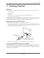
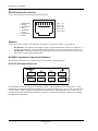
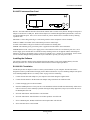
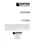
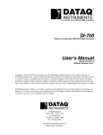
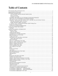
The way PC-based instrumentation should be
DI-1000TC
Instrumentation Modules for Temperature Measurements
User's Manual
Manual Revision M
Copyright © 2012 by DATAQ Instruments, Inc. The Information contained herein is the exclusive property of
DATAQ Instruments, Inc., except as otherwise indicated and shall not be reproduced, transmitted, transcribed, stored
in a retrieval system, or translated into any human or computer language, in any form or by any means, electronic,
mechanical, magnetic, optical, chemical, manual, or otherwise without expressed written authorization from the company. The distribution of this material outside the company may occur only as authorized by the company in writing.
DATAQ Instruments' hardware and software products are not designed to be used in the diagnosis and treatment of
humans, nor are they to be used as critical components in any life-support systems whose failure to perform can reasonably be expected to cause significant injury to humans.
DATAQ, the DATAQ logo, and WINDAQ are registered trademarks of DATAQ Instruments, Inc. All rights reserved.
241 Springside Drive
Akron, Ohio 44333, USA
Telephone: 330-668-1444
Fax: 330-666-5434
Designed and manufactured in the
United States of America
M-100774
Warranty and Service Policy
Product Warranty
DATAQ Instruments, Inc. warrants that this hardware will be free from defects in materials and workmanship under
normal use and service for a period of one year from the date of shipment. DATAQ Instruments' obligations under
this warranty shall not arise until the defective material is shipped freight prepaid to DATAQ Instruments. The only
responsibility of DATAQ Instruments under this warranty is to repair or replace, at its discretion and on a free of
charge basis, the defective material.
This warranty does not extend to products that have been repaired or altered by persons other than DATAQ Instruments employees, or products that have been subjected to misuse, neglect, improper installation, or accident.
DATAQ Instruments shall have no liability for incidental or consequential damages of any kind arising out of the sale,
installation, or use of its products.
Service Policy
1.
All products returned to DATAQ Instruments for service, regardless of warranty status, must be on a freight-prepaid basis.
2.
DATAQ Instruments will repair or replace any defective product within 5 days of its receipt.
3.
For in-warranty repairs, DATAQ Instruments will return repaired items to the buyer freight prepaid. Out of warranty repairs will be returned with freight prepaid and added to the service invoice.
DI–1000TC User Manual
Table of Contents
Warranty and Service Policy ................................................................................................................
1. Introduction ........................................................................................................................................
Features ..............................................................................................................................................
Thermocouple Inputs .........................................................................................................................
2. Specifications ......................................................................................................................................
Signal Connections ............................................................................................................................
Scanning Characteristics ....................................................................................................................
Expansion Capabilities ......................................................................................................................
Max. Sample Rate from Expansion ...................................................................................................
Calibration .........................................................................................................................................
RS-422 Interface ................................................................................................................................
General ...............................................................................................................................................
3. Getting Started ...................................................................................................................................
Unpacking ..........................................................................................................................................
Applying Power to the DI-1000TC Instrument .................................................................................
Connecting the DI-1000TC Instrument to your Computer ...............................................................
RS-422 Interface Port Pin Out ...........................................................................................................
Adapters .............................................................................................................................................
DI-1000TC Instrument Controls and Indicators ................................................................................
DI-1000TC Instrument Front Panel 6
DI-1000TC Instrument Rear Panel 7
Installing the Software .......................................................................................................................
DI-1000-232-F Installation 7
DI-1000-USB Installation 8
Installing Multiple Devices in a Daisy Chain ....................................................................................
4. Module Configuration Software .......................................................................................................
Setting up Addresses for Your Devices .............................................................................................
Calibration .........................................................................................................................................
5. WinDaq® Software ............................................................................................................................
Sample Rate .......................................................................................................................................
Channel Settings ................................................................................................................................
Channels ............................................................................................................................................
User Annotation .................................................................................................................................
Table of Contents
v
iii
1
1
1
3
3
3
3
4
4
4
4
5
5
5
5
6
6
6
7
10
13
13
14
15
15
16
17
18
DI–1000TC User Manual
1. Introduction
Congratulations on your purchase of a DI-1000TC data acquisition instrument for Thermocouple measurements.
This manual is written with the assumption that you have a general understanding of data acquisition, digital I/O and
DSP operations, and that you possess enough proficiency in software to write your own application and/or diagnostic
programs.
Features
The DI-1000TC provides the following features:
•
Expandable: Up to 8 DI-1000TC units (64 channels max) may be daisy-chained together to form one distributed
synchronous data acquisition system.
•
Built-in RS-422 Interface: This allows DI-1000TC units to connect to any host PC through an inexpensive
adapter via an RS-232 or USB port. This RS-422 interface also serves as an expansion port for other DI-1000
Series instruments.
•
Isolation: The DI-1000TC's 1000VDC and Peak AC input-to-output and channel-to-channel isolation allows
grounded TC measurements.
•
High Accuracy and Resolution Design: Allows sharpened decisions with an overall accuracy of ±0.2% of span,
and temperature resolution as fine as 0.08°C.
•
Portable: The DI-1000TC is provided in a small (13.81D × 10.48W × 3.81H centimeters; 5-7/16D × 4-1/8W × 11/2H inches) enclosure consisting of an aluminum base and all-steel wraparound.
The following provides a brief overview of the major subsystems of the DI-1000TC Series.
Thermocouple Inputs
Depending on the model of DI-1000TC you purchased, you will have either 4 or 8 thermocouple inputs. Each input
channel may be configured in software to support one of seven thermocouple types: J, K, T, E, S, B, or R. Temperature measurements may range from -200°C to +1820°C (-328°F to +3308°F), depending upon thermocouple type.
Each DI-1000TC thermocouple channel features a panel-mounted, miniature spade connector, and all input channels
are electrically isolated from ground and each other up to 1000VDC, or peak AC.
Introduction
1
DI–1000TC User Manual
2. Specifications
Signal Connections
The DI-1000TC units are provided in 4- or 8-channel versions. Each thermocouple channel features a panelmounted, miniature spade connector, and all input channels are electrically isolated from ground and each other up to
1000VDC, or peak AC.
Number of channels:
Configurable as 4- or 8-channel modules within one enclosure
Supported Thermocouple Types:
J, K, T, E, S, B, R, mix and match as required
Thermocouple Input Connectors:
Panel-mounted miniature spade, universal TC-type
Open TC detection:
An open thermocouple forces the channel to minus full scale
Cold Junction Sensors:
One for every group of 4 or 8 channels, depending upon configuration
Cold Junction Compensation Range:
-40 to 80°C
Linearization:
Accomplished transparently by the software driver to deliver scaled temperature values to the host program.
Input Impedance:
>1M
Input Bias Current:
50pA
Input Offset Voltage:
<5 V
Maximum Normal Mode Voltage:
250 VDC/Peak AC momentary; 50 VDC/Peak AC continuous
Maximum Common Mode Voltage:
1000 VDC or Peak AC
Common Mode Rejection:
>160db @ 50 and 60Hz
Channel-to-Channel Isolation:
1000 VDC or Peak AC
Input-to-Output Isolation:
1000 VDC or Peak AC
Channel-to-Channel Crosstalk Rejection: >160db
Temperature Coefficient:
<0.04 V/°C
Digital Filtering:
128-tap comb filter per channel, decimating
Voltage Range:
60mV full scale
Scanning Characteristics
Sample Rate:
5 samples/second/channel, fixed
Scan List:
9-position, 8 positions may be programmed for channel number and TC type; ninth position reserved for CJC access
Sample Buffer:
18 samples max.
Expansion Capabilities
Method:
Via integral RS-422 port to other DI-1000 Series Modules
Specifications
3
DI–1000TC User Manual
Max. Sample Rate from Expansion
Units:
5 samples/second/channel
Maximum Distance:
4,000 feet
Calibration
Calibration Cycle:
One year
Calibration Method:
Calibration constants are stored within each module's EEPROM. Provided calibration software to automate calibration in the field.
RS-422 Interface
Supported Baud Rates:
4800, 9600 (default), 19200, 38400, 56800, 115200
Data Bits:
8
Stop Bits:
1
Parity:
None
Protocol:
ModBus ASCII
Connector:
RJ-45
Pinout is as follows:
1
2
3
6
8
Receive (+)
Receive (-)
XMIT (-)
XMIT (+)
GND
General
Panel Indicators:
Power and Active LEDs
Operating Environment:
40 to +80°C
Enclosure:
Aluminum base with steel wraparound. Aluminum end-panels with plastic bezels.
Dimensions:
5-7/16D × 4-1/8W × 1-1/2H inches
13.81D × 10.48W × 3.81H centimeters
Weight:
14 oz. (four channels), 17 oz. (eight channels)
Power Requirements:
9 to 36 VDC, 1 watt
Specifications
4
DI–1000TC User Manual
3. Getting Started
Unpacking
The following items are included with each DI-1000TC Series instrument. Verify that you have the following:
•
DI-1000TC instrument
•
Six-foot CAT-5 cable
•
Power supply
•
The WINDAQ Resource CD. Includes WINDAQ/Lite software and configuration software.
•
Installation Guide (included in CD case).
If an item is missing or damaged, call DATAQ Instruments Customer Support at 330-668-1444. They will guide you
through the appropriate steps for replacing missing or damaged items. Save the original packing material in the
unlikely event that your unit must, for any reason, be sent back to DATAQ Instruments.
Applying Power to the DI-1000TC Instrument
Use the following procedure to apply power to your DI-1000 Series instrument:
1.
Plug the DC power plug end of the power adapter cable into the DC power jack labeled POWER on the rear
panel of the instrument. (There are two identical jacks: either one can supply power, while the other is available
for daisy chaining multiple instruments with one power source.)
Power Adapter Cable
Power Jacks
(one to supply power and one for daisy
chaining power to expansion units)
2.
Plug the other end of the adapter cable into any standard 120VAC, 60Hz, single-phase outlet.
Connecting the DI-1000TC Instrument to your Computer
The built-in RS-422 interface allows the DI-1000TC unit to connect to any host PC through an inexpensive adapter
via an RS-232 or USB port. (All DI-1000 adapters are available through DATAQ Instruments - See below for
details.) There are two identical RS-422 ports. One is to be used to connect to your PC and the other is available for
daisy-chaining power to expansion units.
Getting Started
5
DI–1000TC User Manual
RS-422 Interface Port Pin Out
Use the following diagram for the Pin Out of the RS-422 port.
1
2
3
4
5
6
7
8
White/Orange
Orange
White/Green
Blue
White/Blue
Green
White/Brown
Brown
1
8
Pin 1 = Tx+
Pin 2 = TxPin 3 = Rx+
Pin 6 = RxPin 8 = Gnd
RS-422 Port
Adapters
There are two types of adapters for the DI-1000. You must have an adapter to connect to your computer.
DI-1000-USB - This USB to RS-422 adapter is used to connect the DI-1000 to your PC via a USB port. It
comes with a USB cable. Using this adapter requires installing a driver off of The WINDAQ Resource CD.
DI-1000-232F - This RS-232 (female) to RS-422 adapter is used to connect the DI-1000 to your PC via an
RS-232 port. It comes with an RS-232 cable.
DI-1000TC Instrument Controls and Indicators
The following describes the user accessible items on the DI-1000TC Series instruments.
DI-1000TC Instrument Front Panel
DATAQ
R
INSTRUMENTS
The DI-1000TC units are provided in 4- or 8-channel versions. (The 8-channel version is pictured above.) Each
channel may be configured in software to support one of seven thermocouple types: J, K, T, E, S, B, or R. Each thermocouple channel features a panel-mounted, miniature spade connector, and all input channels are electrically isolated from ground and each other up to 1000VDC, or peak AC. (Miniature thermocouple connectors are available
through DATAQ Instruments.)
Getting Started
6
DI–1000TC User Manual
DI-1000TC Instrument Rear Panel
ADDRESS:
RS-422 - The built-in RS-422 interface allows the DI-1000TC unit to connect to any host PC through an inexpensive
adapter via an RS-232 or USB port. (Both of these adapters are available through DATAQ Instruments.) There are
two identical RS-422 ports. One is to be used to connect to your PC and the other is available for daisy chaining
expansion units.
GROUND - Connect this ground lug to a solid earth ground to ensure compliance with CE standards.
STATUS LAMPS - DI-1000TC Series instruments provide two status lamps:
ACTIVE: This indicator will glow red whenever the instrument is scanning data.
POWER: This indicator glows green when power is applied to the DI-1000TC Series instrument.
POWER INPUT JACK - Allows you to apply power to the instrument. There are two identical jacks: one is to be
used to supply power and the other is available for daisy chaining. Power can be applied with the included power
adapter or you can use an alternate source, as long as it is suitable (+9 to +36VDC @ 3A maximum). Power connectors are available through DATAQ Instruments if you would like to provide your own power source.
Installing the Software
The software required to display and record data from the DI-1000TC can be easily installed directly from the
WINDAQ Resource CD. Choose the installation instructions based on the adapter purchased.
DI-1000-232-F Installation
You MUST purchase an adapter in order to connect your DI-1000TC to your computer. The DI-1000-232F is
designed to connect your DI-1000TC through your PCs RS-232 Serial Port. If you are installing multiple units please
read “Installing Multiple Devices in a Daisy Chain” on page 10 before continuing.
1.
Connect the DI-1000-232F adapter to your computer’s Serial Port using the supplied cable.
2.
Connect the DI-1000TC to the DI-1000-232F adapter using a standard CAT-5 Ethernet cable.
3.
Connect and apply power to the DI-1000TC.
4.
Insert the WinDaq Resource CD in your drive. The installation software should start automatically within 20 seconds. If it does not, start it manually by double-clicking the Setup application (setup.exe) located on the root of
the WinDaq Resource CD.
5.
Select the radio button “Install Software” and click OK.
6.
Select the radio button “Install Software for all other products” and click OK.
7.
Select “WINDAQ/Lite, WWB, and Software Development Kit” and click OK.
8.
Select “DI-1000 Series” and click OK.
Getting Started
7
DI–1000TC User Manual
9.
The Welcome! dialog box allows the user to cancel the installation. Click OK to continue installation or Cancel
to abort.
10. Read the License Agreement. If you accept the terms, click Accept and Continue. If you choose not to accept,
click on the Do not accept and stop button to end the installation.
11. When prompted, specify the directory where you want to install your WinDaq software. It is recommended that
you accept the default. If you have already successfully installed a DI-1000 instrument be sure to install to the
same folder.
12. In the “Interface” dialog box click on the RS232 button.
13. Specify the COM port number (typically COM1) your instrument is connected to and click OK. If you do not
enter this correctly, you may run WinDaq Lite Data Acq Setup from your WinDaq Program Group to change it.
14. When prompted to Select a Program Manager Group specify a destination (or group window) in the Start Menu
for WinDaq software icons. It is recommended that you accept the default.
15. In the “Installation Option” dialog box specify whether you want all users to have access to WinDaq software or
just the current User. Click Yes to allow all users to have access, click No to allow just the current user to have
access.
16. Select the Baud Rate. You should not need to change the Baud Rate - all DI-1000TC modules come pre-configured from the factory. If you do not enter this correctly, you may run WinDaq Lite Data Acq Setup from your
WinDaq Program Group to change it.
17. You should now see the Done! dialog box. Installation is complete. To exit the installation program click OK.
DI-1000-USB Installation
You MUST purchase an adapter in order to connect your DI-1000TC to your computer. The DI-1000-USB is
designed to connect your DI-1000TC through your PCs USB Port. If you are installing multiple units please read
“Installing Multiple Devices in a Daisy Chain” on page 10 before continuing.
1.
Disconnect all DATAQ Instruments USB devices from your PC.
Getting Started
8
DI–1000TC User Manual
2.
Insert the WinDaq Resource CD in your drive. The installation software should start automatically within 20 seconds. If it does not start it manually by double-clicking the Setup application (setup.exe)located on the root of the
WinDaq Resource CD.
3.
In the “What do you want to do?” dialog box, select the radio button “Install Software” and click OK.
4.
In the “Installing Software” dialog box, select the radio button “Install Software for all other products” and click
OK.
5.
In the “Specify the product” dialog box, select “WINDAQ/Lite, WWB, and Software Development Kit” and
click OK.
6.
In the “Specify the Instrument” dialog box, select “DI-1000 Series” and click OK.
7.
The Welcome! dialog box allows the user to cancel the installation. Click OK to continue installation or Cancel
to abort.
8.
Read the License Agreement. If you accept the terms, click Accept and Continue. If you choose not to accept,
click on the Do not accept and stop button to end the installation.
9.
When prompted, specify the directory where you want to install your WinDaq software. It is recommended that
you accept the default. If you have already successfully installed a DI-1000 instrument be sure to install to the
same folder.
10. In the “Interface” dialog box click on the USB button.
11. Make sure all DATAQ Instruments USB devices are disconnected. Click OK to continue.
12. Connect the DI-1000-USB adapter to your computer’s USB Port using the supplied cable.
13. Connect the DI-1000TC to the DI-1000-USB adapter using a patch cable.
14. Connect and apply power to the DI-1000TC. Wait for Windows to complete driver installation.
15. Access the Windows Device Manager and locate the Ports (COM & LPT) icon and click the small “+” sign to
expand the menu and see all the devices installed.
16. Note the COM number that has been assigned to your device and close the Device Manager.
17. Specify the COM port number your instrument is connected to (steps 15 and 16 above) and click OK. If you do
not enter this correctly, you may run WinDaq Lite Data Acq Setup from your WinDaq Program Group to change
it.
18. When prompted to Select a Program Manager Group specify a destination (or group window) in the Start Menu
for WinDaq software icons. It is recommended that you accept the default.
19. In the “Installation Option” dialog box specify whether you want all users to have access to WinDaq software or
just the current User. Click Yes to allow all users to have access, click No to allow just the current user to have
access.
20. Select the Baud Rate. You should not need to change the Baud Rate - all DI-1000TC modules come pre-configured from the factory. If you do not enter this correctly, you may run WinDaq Lite Data Acq Setup from your
WinDaq Program Group to change it.
21. You should now see the Done! dialog box. Installation is complete. To exit the installation program click OK.
Getting Started
9
DI–1000TC User Manual
Installing Multiple Devices in a Daisy Chain
Up to 8 DI-1000TC instruments (64 channels max) may be daisy-chained together to form a distributed synchronous
network.
1.
Connect the first instrument in the chain to your adapter (DI-1000-USB or DI-1000-232) and install it using the
appropriate installation instructions. This is the “Master” instrument.
2.
Run the DI-1000 Configuration Software found in the Windows Program Group specified during installation.
The default is Start > Programs > WinDaq > DI-1000 Config.
3.
Click on Configure > Setup in the DI-1000 Config menu.
4.
Enter “1” in the text boxes for Address, Previous Device, and Master.
5.
If you are daisy-chaining one to four units, select a Baud Rate of 9600 (default) for 1-30 channels or 19200 for
more than 30 channels. If you are daisy-chaining five to eight units, select a Baud Rate of 19200.
6.
Click on Write to configure the instrument.
7.
Disconnect the “Master” instrument from the adapter.
8.
Connect and power the next instrument in the chain.
9.
Enter “2” for Address. Enter “1” for Previous Device, and Master. This device is “Slave 1.” Enter the same Baud
Rate entered in Step 5. For more information on USB ID addresses see “Setting up Addresses for Your Devices”
on page 13.
10. Repeat steps 7 and 8 for each device incrementing Address and Previous Device by one for each subsequent
instrument. Each unit must be powered down after changing the device address or baud rate. Master should
always be “1” and the Baud Rate should be the same for each device.
11. After the setup is complete for all devices in the chain, connect the “Master” unit to the adapter.
12. Insert a standard CAT-5 cable to one of the RS-485/422 ports on the back of the “Master” instrument. It does not
matter which port you insert the cable into.
13. Connect the other end of the CAT-5 cable to one of the RS-485/422 ports on the back of the “Slave 1” instrument.
It does not matter which port you insert the cable into.
14. Connect each instrument in order by Address (assigned in step 9) in the same manner.
15. Power each instrument using one of the Power jacks on the rear of each instrument. Power may be daisy-chained
in the same manner as the CAT-5 cables (four instruments max for each power supply).
16. Once all units have been connected and powered you must change the Target in the Shortcut Properties in
WinDaq Software to reflect the number of “Slave” devices in your network.
a. Right-click on the WinDaq Lite Data Acq DI-1000TC program in the Windows startup menu. Default is Start >
Programs > WinDaq > WinDaq Lite Data Acq DI-1000TC.
b. Click on the Shortcut tab.
c. Change “-N0” to “-Nx” at the end of the Target text box where x is the number of “Slave” units installed in the
daisy chain (total number of instruments minus 1).
Getting Started
10
DI–1000TC User Manual
d. Click OK to close the Properties dialog box.
Your distributed synchronous data acquisition system for thermocouple measurements is installed and ready to run.
Getting Started
11
DI–1000TC User Manual
4. Module Configuration
Software
The following is a brief overview of how to get started with the DI-1000 Configuration Software. A detailed explanation of the configuration software is provided in the help files within the configuration program.
More than likely, you will not need to use the configuration software; it is only necessary when you wish to change
the Baud Rate you will communicate at (the default Baud Rate is 9600), or - if you have multiple instruments that
were shipped separately - to change the modules' addresses. If you want to change the Baud Rate or if you have multiple devices daisy-chained together, you must run the configuration software.
When you install software from The WINDAQ Resource CD, The configuration software (config.exe) is downloaded
in the same directory as WINDAQ in your Start > Programs menu. To configure your device(s):
1.
Connect the device to your PC and then run the configuration software. When the initial screen comes up, select
Configure > Port or click on the Port icon. Then select the port you are connected to. Note: When using a USB
Port it is important to know that Windows automatically assigns a Port that is not necessarily the next Port available on your PC. To find out what Port has been assigned to your USB module check your Windows Device
Manager or try assigning a Port until you get the correct one.
2.
To set your Baud Rate and your Address, select Configure > Setup or click on the Setup icon. Here you can set
your Baud Rate and your Address. This must be done separately for each device. Note that they all must have
the same Baud Rate and the addresses must be synchronized (see below). Note: Each device must be connected
and configured separately - before daisy chaining. Changes take effect when power is re-applied to the instrument (i.e., you must disconnect and reconnect power for changes to take effect).
Setting up Addresses for Your Devices
Note: All modules’ addresses are pre-configured direct from the factory. Setting addresses is only
necessary when changing the configuration of your network (i.e., adding or (re)moving instruments).
The default address for all devices is 1. This is the address for the master device. You can leave it at this address if
you are only running one device. If you take a networked group of instruments and wish to run them all separately,
you must change their addresses to 1 (the Master address). If you then wish to re-create the network (or create a new
network), you will need to change the addresses for all devices except the master. This is done in the Setup window
of the Configuration Software. Each device beyond the master should be numbered sequentially (2, 3, 4, etc.). Each
device must be connected individually to set up its address. In the Setup window, you will have to enter the desired
address for the device you are configuring, the address of the master, and the address of the previous device on the
chain. See the diagram below for an example.
Address: 1
Previous: 1
Master: 1
Address: 2
Previous: 1
Master: 1
Address: 3
Previous: 2
Master: 1
Address: 4
Previous: 3
Master: 1
Master
Slave 1
Slave 2
Slave 3
The use of master and previous addresses for each DI-1000 module allows the modules to synchronize their acquired
readings. Essentially, the master paces the data acquisition scan rate, and each slave follows suit. A typical sequence
is as follows:
Module Configuration Software
13
DI–1000TC User Manual
1.
The master determines that it's time to report a sample, based upon its internal clock and the data acquisition rate
that was programmed for the application. The master reports its data, preceded by its address, as defined by the
ModBus standard.
2.
All slaves connected to the network are programmed to listen for the master's address. This is why Master
Address must be programmed into each slave module. When the master's address is detected, all slaves simultaneously acquire one sample to their internal buffer.
3.
After the slaves acquire their sample, they listen for each other's address, which defines the order in which data is
reported to the network. This is where the Previous Address is used. A slave listens for the module having a base
address equal to the value programmed into it as Previous Address to send its data to the network. After it detects
that the module with Previous Address has sent its data, the module will send its data, preceded by its address.
That address is the address programmed into the next module in the progression as Previous Address. This process continues until all slaves have sent their data.
4.
The master module times out and reports its data to the network, and the process starts all over again.
Of course, this entire sequence takes only milliseconds to occur, from detection of the Master Address to the report of
the final slave. The result is synchronized data acquisition over a distributed network that can be as long as 4,000 feet.
Calibration
Although your device comes from the manufacturer calibrated, you can verify or even change calibration using the
Configuration Software. You should verify your calibration about once a year.
Module Configuration Software
14
DI–1000TC User Manual
5. WINDAQ® Software
In general, WINDAQ software will operate with the DI-1000TC the same way it operates with other instruments. Use
the WINDAQ software manual for instructions on operation. However, there are a few differences that must be noted.
Sample Rate
Edit > Sample Rate: Instead of asking you to specify a sample throughput rate (or total scanning rate) for waveform
recording, WINDAQ with DI-1000 instruments allows you to enter sample rate per channel. For example, if you enter
"5" as your sample rate per channel and you have all 8 channels enabled, your current sample rate (samples per second) would be 40 (samples per channel times the number of channels).
To specify a sample rate:
1.
Select the Sample Rate command:
In the Edit menu click on Sample Rate…
This displays the sample rate dialog box:
2.
Enter the desired sample rate per second in the Sample Rate dialog box.
3.
Click OK or press the ENTER key.
WINDAQ/Lite automatically allocates the correct amount of buffer space when you input a sample rate. The Input
Buffer Size and Disk Buffer Size values are displayed for informational purposes only.
WinDaq Software
15
DI–1000TC User Manual
Channel Settings
Edit > Channel Settings: Channel Settings allows you to select the thermocouple type you are using for each channel
and whether you want your data to appear in °F or °C. (°C is the default. You can toggle between °F and °C by selecting and deselecting the "Fahrenheit" check box.) Once you have selected your thermocouple type, that thermocouple's default full scale range will appear under -FS °C and +FS °C. (You can change this range by going to Scaling >
Limits.) Once you have made the appropriate changes to your application, click OK.
WinDaq Software
16
DI–1000TC User Manual
Channels
Edit > Channels: Channels allows you to select which channels on all of your DI-1000 devices you want to acquire
data. Channels are selected by placing a check mark in the appropriate box. You will find the addresses of your
devices under the "Addr" column. If you are only using one device, you will select channels in the row across from
the "1" in the Addr Column. If you are using a four-channel device, you will only be able to select channels 1-4. If
you are using an eight-channel device, you can select channels 1-8. (Channels 1 through 6 are selected in the graphic
below.)
If you have more than one device, you will be able to select more channels. The second device's channels would be
selected across from the 2 in the "Addr" column on the right of the window. These channels are labeled 9-16 and they
correspond with 1-8 on your device. For example, if you wanted to select channels 1-4 and 7-8 on your second
device, you would place a checkmark in the 9-12 and 15-16 boxes. When you are looking at data in the WINDAQ
software, the channels will be identified by the numbers designated in this window. For example, the third channel
on your second device will be identified as Channel 11. Any more than two devices will follow the same pattern (odd
device addresses will have channels between 1 and 8 and even device addresses will have channels between 9 and
16), although they will have a letter appended to the channel number. For example, device 3 channels will be labeled
1A, 2A, 3A, etc., while device 10 channels will be labeled 9D, 10D, 11D, etc.
Once you have selected the channels you would like to record, click OK.
WinDaq Software
17
DI–1000TC User Manual
User Annotation
Edit > User Annotation: This allows you to annotate each channel to make them easily recognizable in the WINDAQ
screen. Highlight the channel you would like to annotate by clicking on it and then go to Edit > User Annotation.
This will reveal the dialog box shown below.
The entire annotation entry can not exceed 32 characters. The section before the colon is the name of the device you
are using. (This is especially helpful if you are using more than one device.) The section after the colon is an annotation for the channel you have selected. For example, you may be comparing multiple engines in different locations.
You may want to label your first channel, "Room1:Battery", as shown above. Then you can hit "OK" and apply the
new annotation, or go to another channel by clicking "Next" to annotate the next channel, "Previous" to annotate the
previous channel, or by entering a different channel in the "Channel # =" text box.
When you are looking at your WINDAQ screen, the new annotation will appear on the waveform in red, as shown
below.
:
User Annotation can be turned on and off at any time by going to Options and deselecting User Annotation or by
pressing Alt + U.
WinDaq Software
18
DATAQ Instruments, Inc.
241 Springside Drive
Akron, Ohio 44333
Telephone: 330-668-1444
Fax: 330-666-5434
E-mail: [email protected]
Direct Product Links
(click on text to jump to page)
Data Acquisition | Data Logger | Chart Recorder | Thermocouple | Oscilloscope