1
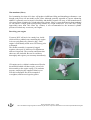
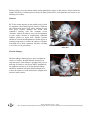
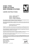
Thank you for purchasing an RCV model engine. The RCV engine operates on a unique
mechanical principle that employs a one piece cylinder/valve which is driven around a
conventional reciprocating piston and crankshaft assembly at half crank speed to facilitate a four
stroke cycle of operation. The diagrams and photographs in this manual should clarify the elegant
operating principle of your RCV engine. Following the very first proof of concept RCV, today’s
production units have evolved into the current reliable and thoroughly practical range of model
engines.
Background
The RCV Rotating Cylinder Valve engine is a unique concept enjoying world patents. In 1997 Keith
Lawes, a keen aeromodeller and a Cambridge mathematics graduate invented the RCV engine and
helped to form RCV Engines Ltd, the company. RCV continues to develop an increasingly diverse
range of rotating cylinder valve engines, for the aeromodelling, aerospace and automotive industries.
All RCV engines operate on the four-stroke principle. Due to the unique mechanical arrangement of
the RCV concept, there is just one extra moving part over the far less efficient two-stroke engine,
thereby facilitating a four stroke cycle of events. RCV’s unique rotating cylinder valve has eclipsed
the need for the usual complicated four stroke valve train, whilst proving extremely durable and hard
wearing. With beneficial cylinder wear and heat distribution properties over conventional engines
and nothing to adjust, unlike a poppet valve system, your RCV engine is practically a maintenance
free unit and with due care and consideration it will last you a modelling lifetime.
A few “Do’s and Don’ts”
As with any new engine, the temptation to try out your purchase immediately will be a strong one,
but we strongly urge you to read this information (or the instruction manual included with the engine)
before you attempt to start your new RCV. If your engine isn’t to be used to power a model in the
foreseeable future you will need to carefully clean all fuel residues and oil liberally before you lay it
up - Internal corrosion can result from bench running followed by a extended storage periods if the
unit is not.
If the engine is to be used in the near future, then just a few words of caution prior to starting your
new engine. Use only our recommended fuel types and be sure to use a dedicated four-stroke
glowplug. We only recommend the OS “F” type, having found it to be eminently suitable. Using the
wrong fuel and plug will almost certainly result in an indifferent idle and slow running performance
and in extreme cases could lead to engine damage.
Lubricants
Pure castor lubricants are not recommended because of their propensity to gumming and carbon
deposition. Following extensive long term tests under a range of conditions we now recommend a
synthetic / castor lubricant and a fully synthetic lubricant based fuel. We have enjoyed excellent
results following extensive testing with Model Technics Duraglo & Weston Prosynth 2000.
Alternative fuels we recommend are: Morgan Omega 10%, Wildcat Premium 10%, Byron Premium
Sports 10%. Other fuels, however suitable, have not been evaluated by RCV so we cannot therefore
guarantee their performance.
d
Photo User Guide Issue 1 – 2005
This is an additional support guide and should only be used in conjunction with the RCV user manual provided with the engine
Nitromethane (Nitro)
Fuel containing less than 10% nitro will produce indifferent idling and throttling performance even
though peak power will not unduly suffer. Nitro, although generally regarded as a power enhancing
additive is primarily used to improve flexibility and throttle response. Be wary of fuel manufacturers
who quote liquor quantities by weight rather than volume. Nitro is a great deal heavier than methanol
(or oil) and as a rough guide fuels quoting contents by weight will need a 15% Nitro mix! Using
appreciably more than 10% Nitro (by volume) is not recommended as the increased cylinder
pressures invoked may overstress your engine.
Receiving your engine
Your new RCV will arrive in a sturdy box, inside
which will be a padded wrap containing the engine
in its own polythene oily protective bag. Each
engine is individually tested at our UK factory prior
to dispatch.
The muffler assembly is separately bagged,
together with a pair of Allen keys for adjustment
and servicing needs. The warranty and instruction
sheets are also included. Be sure to read these
thoroughly and register your warranty immediately.
Receiving your engine
CD engines arrive with their carburetors affixed to
the manifold which will then require you to bolt
this assembly to the engine casing. Use moderate
pressure, employing the supplied Allen keys to
affix this component. Do not be tempted to
overtighten, and Do not forget the gasket
CD Series Carburettor
d
Photo User Guide Issue 1 – 2005
This is an additional support guide and should only be used in conjunction with the RCV user manual provided with the engine
There is a plastic plug sealing the inlet nipple and
this, together with the breather nipple on the
crankcase on the CD models, will need removing
before use. These covers are a protective measure
only for storage purposes
Remove the black plug- this is for storage only
Initial starting and running in
Starting your new RCV for the first time should be an enjoyable and trouble free experience
providing you adopt a methodical and workmanlike approach.
The engine should be firmly mounted in a safe environment. The SP models drive huge propellers
and must be mounted accordingly due to the torque reaction from an 18 –20 inch coarse pitched
propeller, which is considerable. Do not run your engine in an enclosed space such as a your
workshop or the garden shed due to the very real risk of carbon monoxide poisoning. Do ensure that
all clothing is secure and that rags and the like are not casually left on the bench.
Anything that can get caught in the propeller will in all likelihood be ingested with potentially
dangerous results. Ensure that there is plenty of room to walk around your engine whilst running it so
that you remain out of harms reach at all times. Never stand in front or to the side of the propeller
whilst an engine is running. In the eventuality of a thrown propeller or part thereof, your only place
of safety is behind the propeller arc. Tachometer measurements should always be taken from the rear
and we advocate that you stop the engine to make fine carburetor adjustments for your own safety.
Propeller selection
Whilst your eventual propeller selection will depend on the model that the engine is used in, for
initial running in purposes and general handling familiarity we recommend the following propellers.
RCV 58 CD – 12 x 6
RCV 91 CD – 14 x 6
RCV 60 SP – 16 x 12
RCV 90 SP – 18 x 12
RCV 120 SP – 18 x 12 or 20 x 12
We have extensively tested a wide variety and range of propeller types and sizes and the sizes
indicated above represent a good general choice for engine familiarisation and general flying. In
practice we have also enjoyed good results with APC’s 12.25 x 3.75 (dedicated fun fly) propeller on
the 58CD in lightweight aerobatic models. APC’s 13 x 6 / 14 x 6 / 15 x 4 perform well on the 91 CD
with the smaller diameters more suited to faster flying WWII fighter types and the like.
d
Photo User Guide Issue 1 – 2005
This is an additional support guide and should only be used in conjunction with the RCV user manual provided with the engine
The SP models will disappoint if propellers with less than 10 inch are employed due to their geared
outputs which halve the output RPM (whilst doubling the torque) over conventional model aero
engines (ie half the RPM = twice the torque = twice the pitch required)
We recommend APC propellers (& other glass composite props) finding these to be both efficient
and quiet. RCV carry stocks of these in suitable sizes should you have difficulty obtaining the correct
propeller from you local dealer. As an approximate guide, your SP should be fitted with propellers
that rotate between 5000 and 6000 RPM whilst the 58 CD and the 91 CD run most efficiently
between 9000 and 13000 RPM. Propellers should be employed that load the engines to these speeds.
Three and four bladed propellers will need to be
reduced in size by approximately one inch in
either pitch or diameter per blade increase. One of
the great benefits of the SP series engines is that
they pull large scale like 3 & 4-bladed props.
We have extensively tested the SP range on three
and four bladed propellers and can supply suitable
sizes or offer suggested fitments.
16x10 3-bladed prop on RCV60SP
Wooden Props – RCV don’t recommend the use of wooden propellers as quality and weight can
differ significantly. In generally wooden props are much lighter than glass composite propellers and
so do not give the desired flywheel effect. This can result in increased vibration on the SP series
engines. Saying this however, many of our customers have used wooden propellers successfully.
Zinger Propellers seem to work well with our engines.
Starting a the new engine
New engines will be very tight and may on occasion prove reluctant to turn sufficiently briskly with
some less powerful starters. New 15 and 20cc units will need a fairly powerful starter initially
although once broken in, frictional resistance will be greatly reduced which makes starter
performance less demanding. Ensure that your starter leads are sufficiently robust and that your
battery is capable of delivering the amperage needed to turn the engine at a reasonable speed for
starting. Corroded or very small battery connectors allied to long lightweight leads will almost
certainly cause your engine to rotate too slowly to start.
The SP series requires your starter to rotate
clockwise, meaning that the leads will be reversed
from convention due to their geared output shafts
which reverses the direction of the drive. Finally,
some power panels are rather less than capable of
supplying sufficient current to maintain a good
glow whilst driving a powerful starter
simultaneously and for that reason we advocate a
separate glow battery.
Starting the SP engine from behind the prop
d
Photo User Guide Issue 1 – 2005
This is an additional support guide and should only be used in conjunction with the RCV user manual provided with the engine
Behind the propeller starting is potentially the
safest method for any model engine operation and
with the SP range this is strongly advised.
Study the photographs paying particular attention
to the reversal of the battery leads on your starter.
This is necessary due to the gearing which reverses
the propeller direction on these models.
If starting from behind the propeller,
remember to reverse the leads!!
Running In
Running in your new RCV is simple if a few basic rules are followed. These are not RCV rules per
se; but rather rules for running in any engine.
1
Ensure that your engine is securely mounted, having previously gone over every fixing on
the unit and in particular the carburetor screws & muffler, ensuring that these are tight. Do
not overtighten anything, but do ensure that nothing is about to drop off or loosen. Like
any other production engineered product, human error may well throw up the odd fixing
that hasn’t been fully tightened and checking before running is therefore a sensible
precaution.
2
On the CD series do not open up the engine mounting holes. This can weaken the engine
crankcase so is not recommended.
3
We strongly advocate familiarisation in a test stand environment, but should you decide to
fit your engine directly into the model, this will suffice for the purpose of running in the
CD series, providing that you run a few tanks of fuel through on the ground first. Break in
times vary with most engines needing one to three hours of accumulated time before
giving their best. The SP models tend to need more time than the CD models, particularly
the 120 which has a lot of large components to bed in. During the run-in period vibration
may be higher so it is best carried out on a test stand.
4
All RCV engines are run prior to dispatch, therefore carb settings will be pretty much set.
Running your new engine for the first time should be executed in relatively short bursts –
say 3 to 5 minutes with a measurable period of cooling between runs. Set the needle rich
and run the engine initially on about half throttle which will allow things to bed in nicely.
After half an hour of accumulated time run the engine for short full power bursts, but still
on a slightly rich setting, gradually increasing the workload of the unit until it feels
“snappy” and it will hold peak RPM without sagging. At this juncture you can attend to
the low speed mixture setting. If adjustment is needed it should only require a ¼ turn
either way. There is little point in trying to adjust this initially with a tight engine.
d
Photo User Guide Issue 1 – 2005
This is an additional support guide and should only be used in conjunction with the RCV user manual provided with the engine
Adjusting the main needle
Adjusting the idle needle
Settings
Your carburetor will in all likelihood be set very rich on the slow running or secondary needle as
supplied from the factory as previously mentioned. This is intentional as it ensures that the engine
will start, given that four strokes need to be relatively rich when compared with a two stroke
counterpart. We suggest that you pay little heed to the secondary setting for the first 15 minutes of
running as the newness of the engine will preclude accurate settings and it is far better to err on the
rich side to begin with.
The main needle valve setting will need to be
somewhere between three quarters and one and a half
turns open from fully closed but tank position and
plumbing issues will affect this to a degree. The
throttle must be fully open when this adjustment is
checked. With the throttle barrel in the closed position
the main needle will bottom out against the spraybar.
Spraybar end
All four stroke model glow engines need to be wet for
cold starts. To affect a choke mechanism, simply place
a finger over the inlet venturi with the throttle wide
open. Turn the “choked” engine over a few times by
hand until fuel is drawn into the carburetor. Close the
throttle to about one third and turn the engine over a
couple of times to check for flooding or hydraulic
locking before energising the glowplug and starter.
With sufficient richness and a good glow the result
will be an immediate start.
d
Photo User Guide Issue 1 – 2005
This is an additional support guide and should only be used in conjunction with the RCV user manual provided with the engine
Placing a finger over the exhaust outlet whilst spinning the engine on the starter will also choke the
engine effectively if exhaust pressure feeds the tank system but be aware that this can lead to severe
flooding if overdone.
Silencers
RCV four stroke engines are not unduly noisy but all
are supplied with a small (typical) silencer. Silencers
can vibrate loose and if your engine mounts are less
than good, silencer damage can result from
continued running with the resultant severe
vibration. Almost all silencer woes can be attributed
to poor engine mounts or insufficiently tightened
exhaust systems to begin with. Exhaust systems
should be rechecked and tightened with the engine at
running temperature to reduce the chances of further
loosening due to heat expansion. Periodic checking
is of course a wise precaution.
Exhaust Locking nuts should be retightened
when hot
Throttle linkages
Throttle linkages should enjoy a direct straight run
wherever feasible. Reliable throttle operation can
only take place if the linkage is geometrically correct
and slop or bind free. On typical ARTF installations,
the supplied (usually) wire for the throttle linkage
should be insulated with heat shrink tubing here to
reduce the chances of radio interference (slight) from
metal to metal contact.
Insulation here
d
Photo User Guide Issue 1 – 2005
This is an additional support guide and should only be used in conjunction with the RCV user manual provided with the engine
On Board Glow Systems
On board glow systems are worthwhile for multi engine scale models where the ultimate in reliability
is paramount. We have enjoyed successful results with the Telco glow driver which operates
“intelligently” by supplying current to the plug on demand only.
Telco on board glow system – Sub C cell will facilitate both starting and flying whilst a
single AA cell is sufficient for flying only
Trouble shooting
If your engine refuses to fire then check your plug and particularly your glow battery - the plug
element should be an orange colour when energised – rather than a dull red. Check the rotational
direction of your starter. We have had many SP owners try to start their engines backwards with the
starter rotating anti clockwise (ie the conventional direction) and it’s a common mistake! With a
healthy bright orange glow allied to sufficient richness and with the throttle set to one third your
RCV will start very quickly. All RCV engines are easy and quick starters and a logical and
methodical approach will soon determine any reason for failure.
Warranty claims
Providing your RCV engine is operated in accordance with these instructions it is guaranteed against
all manufacturing defects for a period of 2 years. RCV engines Ltd are UK based and we are
available to answer technical or warranty enquiries by email or telephone. If your engine needs to be
returned for any reason, please use the original packaging and documentation.
Applications
Customers have fitted the entire range of RCV
engines to a very diverse selection of model
types worldwide. Some of the more exotic or
unusual models have been made known to us
and our technical team, all keen aeromodellers,
will be more than happy to offer advice and
information should you have an unusual
project in mind. Some extremely sophisticated
competition winning scale models have
benefited from the unique characteristics of
their RCV engine(s).
d
Splendid scratch build Flying Flea powered by
RCV58CD
Photo User Guide Issue 1 – 2005
This is an additional support guide and should only be used in conjunction with the RCV user manual provided with the engine
Hangar 9 ARTF Mustang – RCV 91CD powered
– note how the compact nature of the CD
facilitates a fully cowled engine
FAQ
How powerful is my RCV engine?
Whilst our engines are not as powerful as out and
out competition types, having been engineered for
reliability and longevity, they all perform
willingly and enjoy excellent handling
characteristics. Testing has show them to perform
similarly to other sports four strokes of similar
capacity, with the very real RCV advantages of
low maintenance and reduced physical
dimensions.
RCV91CD is the same physical height as a
typical 48/52 conventional 4-stroke
What is the fuel consumption of an RCV engine?
The whole range is remarkably frugal. In practice
an 8oz tank will prove sufficient for the 58 and 60
SP increasing pro-rata for the 90/91 up to the 120
SP where a 16 to 20 oz tank should prove adequate
for most applications.
16 oz tank in Hangar 9 Mustang gives more
than adequate duration for its RCV 91 CD
d
Photo User Guide Issue 1 – 2005
This is an additional support guide and should only be used in conjunction with the RCV user manual provided with the engine
Mounting your engine
The SP range produce huge torque and drives very
large diameter propellers and for this reason these
models must be very well mounted. We supply a
dedicated back plate mount designed to spread the
load of the mounting points to prevent the firewall
of your model crushing. You should always use this
when mounting your SP and pay particular
attention to the suitability of the structure of the
model in the appropriate areas. If you are looking
at using the engine in more than one model you can
purchase additional backplates from RCV
RCV SP series backing plate
Cowling your RCV
Cowling any RCV engine is easily achieved due to
the very compact nature of the design. Be very
aware that your RCV, like any other IC aero
engine, must be adequately catered for in the
cooling department. Because of the reduced
physical dimensions over other engines of similar
power and displacement, this can be overlooked.
The examples shown here give an indication of
good practice. Full sized aero engine installations
may look as though they have relatively small
entry and efflux ports but upon closer inspection
cowls are ducted to direct air directly over the
cooling fins and you should replicate that situation
too.
Mustang cowl has additional outlets for cooling air – as
a general rule outlets should be three times the area of
inlet holes
3D from Modeltech is powered by RCV 91 CD – cowl inlet has been carefully shaped to force air over the cylinder
head – cowl bottom has been drilled and relieved to ensure that it can escape again
d
Photo User Guide Issue 1 – 2005
This is an additional support guide and should only be used in conjunction with the RCV user manual provided with the engine
Ultimate powered by RCV 60 SP – cowl ducts air directly
towards engine fins
How do I maintain my RCV and keep it in tip top condition
We strongly recommend that you run the engine dry
after use to remove all unburned fuel residue as this
is extremely corrosive. Methanol is Hygroscopic,
meaning that it retains water and moisture retention
will invoke rust and general corrosion problems.
Disconnect the fuel feed from the carburetor and
restart the engine, repeating the operation until the
engine refuses to fire any longer before storage.
Never leave raw fuel in your engine and where
possible, always disconnect the fuel feed from
carburetor after use. A small piece of oily rag or
tissue used to block inlet and exhaust orifices will
help to prevent moisture ingress during storage.
Finally, store your model nose UP. This prevents fuel and exhaust residue running back into the
stored engine, minimising problems. Keep your engines clean and dust free and treat your RCV as
the precision miniature engineering device that it is, both during use and in storage.
Crash damage
We at RCV appreciate only too well that model aeroplanes crash from time to time. The engine is
invariably the first point of contact with terra firma and damage can be almost inevitable following
and accident.
If the engine looks damaged in any way at all then resist the temptation to rotate it to check for bent
or broken parts as this may exacerbate things. Dirt or mud should be washed off using a toothbrush
under a running tap followed by a liberal spray with a WD fluid. Closer inspection will reveal how
serious the damage is and should you suspect a bent crankshaft or displaced bearings or worse then
remove the engine from the (remains of…) the model, spray with a proprietary WD protection fluid
and return the unit to RCV for a repair quotation.
d
Photo User Guide Issue 1 – 2005
This is an additional support guide and should only be used in conjunction with the RCV user manual provided with the engine
For those that feel confident enough to undertake maintenance or repair work themselves, the
following information will prove useful. Be aware that whilst both SP and CD types are simple to
dismantle, there are one or two parts that may get lost during disassembly, such as Woodruff keys
and in particular the PTFE pad that locates on one end of the gudgeon pin. When putting your engine
back together it is essential of course that the cylinder valve is correctly timed.
As from 1st August 2005, if you return your warranty form within 1 month of purchase, you will
automatically benefit from our lifetime repair offer. Therefore even if you crash your engine, you
will never have to pay more than 50% of the cost of a new engine (RCV RRP) to cover repair or
replacement.
Reassembling and timing the RCV
Timing the Cylinder (on all engines)
The rotating cylinder on all RCV engines has to be
timed with crankshaft rotation. RCV assembly and
timing is infinitely more simple than similar work on
conventional poppet valved four stroke engines and
with care, is foolproof. The correct timing placement of
the cylinder valve assembly will be effected when the
cylinder port is equidistant between the inlet and
exhaust orifices in the casing.
with cylinder correctly held in position in its
casing, carefully engage the gear to the
crankshaft with piston at TDC
This can be achieved visually by holding the unit up to a window or light and peering intently
through the ports but for absolute certainty a very small plastic tie wrap passed through the inlet and
exhaust will lock the cylinder in place in its housing. Carefully bring the piston to top dead centre by
rotating the crank assembly ensuring that the small PTFE pad remains in situ on one end of the
gudgeon pin before gently lowering the cylinder over the piston as you gently compress the ring. The
piston ring is free to rotate meaning that orientation of that component is non critical, but it is
essential that the crankshaft remains stationary during this operation until the gears are meshed
d
Photo User Guide Issue 1 – 2005
This is an additional support guide and should only be used in conjunction with the RCV user manual provided with the engine
SP models can be assembled with the two halves of
the engine in one of four orientations, making scale
model installation very flexible. As long as the
rotating cylinder is correctly timed to the crankshaft,
all will be well. Changing the orientation of the outer
cylinder will NOT reverse the rotational direction of
the engine (a common misperception).
Changing the Orientation of the outer cylinder
Storage
Models not in use should be have ALL traces of fuel removed from the engine (ie start and run DRY)
before being hung from a suitable hook nose UP. Storing your model nose UP is very beneficial
because it ensures that no nasty corrosive exhaust by products run back into the engine during the lay
up period. Storing nose UP also ensures that should you be less than vigilant with the
aforementioned, at the very least these corrosive elements will rest on the backplate of the unit, rather
than in the bearings, thereby minimizing the risks of corrosion damage. Suitable lay up oils are now
commercially available expressly for the purpose allied to which blocking the inlet and exhaust
orifices with an oily tissue will help things stay in fine fettle. Store your models in a dry area which
should ideally be free from dust and cold damp air. If this isn’t feasible and you really do have to
resort to the rafters in your unheated garage then removing the engine for prolonged storage is
advocated. Corrosion damage can be terminal and more engines are ruined this way any.
d
Photo User Guide Issue 1 – 2005
This is an additional support guide and should only be used in conjunction with the RCV user manual provided with the engine