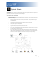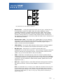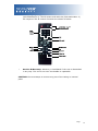
1
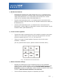
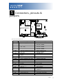
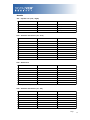
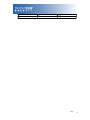
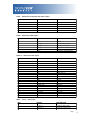
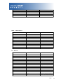
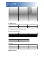
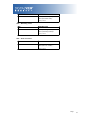
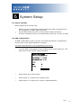
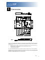
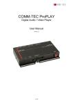
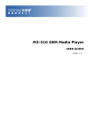
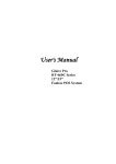
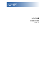
M3-320 USER GUIDE Version 1.1 Revision History Amendment Date Version March 2009 V1.0 September, 2010 V1.1 Page 2 Table of Contents 1 Introduction ................................................................................4 2 System Design .............................................................................6 3 Quick Start ..................................................................................8 3.1 Prepare for connection .................................................................................................................8 3.2 Basic connection for M3-320.......................................................................................................9 4 General Notes ............................................................................10 5 Connectors, pinouts & jumpers .....................................................13 6 System Setup ............................................................................22 6.1 Select switches ...........................................................................................................................22 6.2 OSD Configuration ....................................................................................................................22 6.3 Start up .......................................................................................................................................23 6.3.1 Start track mode ..............................................................................................................23 6.3.2 Sleep mode ......................................................................................................................23 6.4 Loop Playback............................................................................................................................24 7 Operating Instructions .................................................................25 7.1 Operating modes ........................................................................................................................25 7.1.1 Playlist mode...................................................................................................................25 7.1.2 Simple play mode............................................................................................................25 7.2 Operating functions ....................................................................................................................26 7.3 USB Update................................................................................................................................27 7.4 Formatting SD card ....................................................................................................................29 7.5 Exporting Project and Playlist....................................................................................................30 7.6 Network setup ............................................................................................................................31 8 Dimension .................................................................................33 9 Specification ..............................................................................34 Page 3 1 Introduction This brief guide explains how to use and set up your M3-320 decoder board. It is intended for Digital View staff who assemble ViewStream product for demos or for customers, and for resellers. The M3-320 is an MPEG decoder board designed to use with Video Monitors for playing MPEG-2/MPEG-4 video and audio files. MPEG-2, MPEG-4* video JPEG picture MP3 audio file Video signals of PAL & NTSC standard Composite signal output DVI output Audio output RS-232 port USB Update LAN (RJ-45) port * DivX MPEG-4 format IMPORTANT USAGE NOTE ☞ All media filenames must be in 16.3 format (e.g. xxxxxxxx.xxx) though combinations with 7.3, 10.3 etc are fine. Where: ☞ “16” is the maximum of alpha-numeric character to be used. “3” is the file extension like .mpg / .jpg / .avi etc. Do not use any “Non alpha-numeric” characters like ‘~’, ‘_’, ‘-‘, ‘&’, ‘^’, etc. NOTE: If ‘Non alpha-numeric character’ or the ‘8.3’ format are not followed, the player will not recognize the playlist. This equipment is for use by developers and integrators; the manufacturer accepts no liability for damage or injury caused by the use of this product. It is the responsibility of the developer, integrators or other users of this product to: Ensure that all necessary and appropriate safety measures are taken. Obtain suitable regulatory approvals as may be required. Check power settings to all component parts before connection. DISCLAIMER There is no implied or expressed warranty regarding this material. Page 4 Page 5 2 System Design M3-320 Connector Summary: Summary: 1. Switches and buttons connector (1 13. Power input (DC 12V) – 8 button) 1. Reserved 14. COM port 1. Remote Ext. (1-8 button) 15. Alternative Composite out and audio out 1. Switches and button connector (9 16. Audio out (Line out) – 16 button) 1. SD card slot 17. DVI / VGA out 1. Power / Status LEDs 18. Composite out 1. USB connector 19. LAN port (RJ-45) 1. IR connector 20. Reserved 1. Power on/off switch connector 21. DIP switch (4-pos) 1. Speaker out connector 22. Alternative LAN (WiFi) 1. Alternative DVI out 1. Alternative VGA out Page 6 A) Mechanical buttons • Standard MV-switchmount (P/N:416101300-3) for 1-8 buttons when connected to the button connector CN6 via the standard switchmount cable (P/N:426451100-3) or connected to the Remote Ext. socket (CN5) via the standard cable (P/N:426631800-3). • Custom made switchmount for 1-16 buttons when connected to the buttons connector CN6 and CN3 via the standard switchmount cable (P/ N:426451100-3) • Custom made switchmount for 1-8 buttons when connected to the Remote Ext. socket (CN5) for alternative remote control buttons via the standard cable (P/N:426631800-3). B) Touch screen segments • The M3-320 when connected with a LCD interface controller can output videos on to LCD screen. Button control can be performed via touch screen for panel sizes of 7”, 8”, 10”, 15” and 21.5” • There is one type of button pattern layouts on the touch screen available: 8 buttons (For any special button layout, please contact local sales office.) Fig. 1 8-buttons for LCD touch screen C) Button function settings • Whether the buttons are of the mechanical type (on the standard switchmount or custom made) or the touch screen segment type, each button function can be programmed with the DV Studio Software program to perform a VCD player mode function or specific track select function. (See DV Studio Software user manual). • The DV Studio Software program is separately provided Page 7 3 Quick Start CAUTION: Never connect or disconnect parts of the system when the system is powered up as this may cause serious damage. 3.1 Prepare for connection Connection and usage are straightforward. However, care needs to be taken with the following: • Ensuring parts have been correctly connected – both power & signal considerations. • Checking that all switches and jumpers are set correctly. • The input signal is compatible. • Legal & safety requirements have been met. • If you are using supplied cables & accessories, ensure they are correct for the model of video monitor. • If you are making your own cables & connectors refer carefully to the video monitor specifications and the “Connectors, Pin outs & Jumpers” section in this user guide to ensure the correct pin-to-pin wiring. Page 8 3.2 Basic connection for M3-320 • Connect the keys pad to CN5 (if required) • Set the DIP switch#1 (S3) to the chosen output connector. • If Composite video output is selected, set the DIP switch#2 (S3) for “PAL” or “NTSC” selection. • Connect the video and audio ext. cables from the M3-320 to the monitor. • Connect the power supply (DC 12V @ 1.2A minimum. - ensure correct + & - orientation) to the controller power input (PP1). • Connect the on/off switch cable (p/n:426680401-3) or short Pin1-2 at PW1 for “Auto power on” For a detailed system setup, go to section 6 Page 9 4 General Notes The M3-320 is designed for use with Video Monitors and other analogue signal input displays. Here are some notes for correct use: • Preparation - Before you proceed, please familiarize yourself with the various connectors, jacks, switches and function buttons of the M3-320 unit (see the ‘System Design’ diagram). • The unit - Handle the unit with care; any knocking may cause components to come loose and disconnect. Operate in a cool and dry place. • Power Input: 12V DC, 1.2A (minimum) is required; this should be a regulated supply. Power connector is using DC jack, 2.5mm diameter (Center +) • Video output – Video - displays PAL & NTSC signals with composite out. The PAL/NTSC switch should be set correctly. • Audio output – Audio - Stereo output. Master volume is controlled through OSD with switch mount buttons. • DIP Switch settings (S3) – To define and select the source of output and USB/LAN. o SW1-1 (Output selection): DVI/VGA: If it is selected, the output resolution is set to 1280x720p60Hz* Composite: If it is selected, the video format (PAL/ NTSC) is determined by SW1-2. o SW1-2 (PAL/NTSC selection): When using Composite output connectors this should be set according to the input requirements of the video display being used. o SW1-4 (Content update selection): You may only choose either one way (LAN or USB) to update content without removing SD card. Page 10 *An optional DVI to VGA adapter is required • Remote Ext. - Using the standard switch mount (p/n: 416101300-3) 8 momentary buttons for OSD config and video playback control (standard functions (in simple play mode) being: Play, Stop, Pause, Next Track, Volume decrease, Volume increase, Mute). An optional function control device is a custom-made switch mount connected to the switches and buttons connectors (CN6 and CN3) with a maximum of 16 momentary buttons • Remote Ext. cable - The cables (p/n: 426631800-3) to the switches and buttons connector should be of suitable quality and length so that impedance does not affect performance. Generally lengths up to 1 meter (3 feet) should be acceptable. • LED (LED2) - The power LED indicator shows power is being supplied to the M3-320. The Status LED indicates the status of SD card. • RS-232 port – Requires RJ-11 to DB-9 extend cable (p/n: 426894301-3) for RS-232 connection. This serial port supports barcode scanner and RS-232 command control. The baud rate must be set to (9600, n,8,1) and record suffix is set to CR (0DH). • USB – USB Host. Use USB memory stick for content update without removing the SD card. The M3-320 will reset power when the USB stick is detected inserting into the USB connector or removing from the USB connector. (For the details of USB content update, please refer to the Application note.) • DVI out – Supports DVI or VGA. Both DVI and VGA signal are sharing the same connector. A DVI to VGA adapter is required if connect to VGA. Note: This DVI/VGA out is currently set to 1280x720 resolution which may not be supported by all monitors. If the display looks reasonable but not perfect please use the OSD settings of the monitor to adjust image position and tuning. (sometimes called Phase, H. size, H. Freq, etc) It may also be necessary to adjust image size. Page 11 • Infra-red (IR) - Supports IR control with DV remote control handset (P/N:559000104-3). The IR sensor and cable kit (P/N:446010401-3) are required. The IR control functions are shown as below. • Service & Warranty: Warranty is invalidated if the unit is dismantled in any way. The unit is not user serviceable or repairable. CAUTION: Do not attempt to remove any part of the casing or internal parts. Page 12 5 Connectors, pinouts & jumpers The various connectors are: Ref Purpose CN1 CN2 Speaker out (L/R) connector Reserved CN3 Switches and buttons connector (#9 - #16) Reserved CN4 CN5 CN6 CNV2 HDMI 2 LED2 J1 J2 J9 J10 USB1 LAN1 P2 PP1 Remote Ext. (#1 - #8) Switches and buttons connector (#1 - #8) Reserved Alternative Composite and Audio output Alternative VGA output Alternative DVI output Power (up)/Status (dn) LEDs Audio out (Line out) Composite video out SD card connector RS-232 USB connector LAN connector DVI out Main power input S3 PW1 JA1 IR1 Video out / USB / LAN switch Power On/Off switch connector Internal power set IR Connector CN8 CNV1 Description JST B4B-XH-A Hirose 1.25mm, 4-pin, DF13-4P-1.25DSA Hirose 1.25mm, 9-pin, DF13-9P-1.25DSA Hirose 1.25mm, 6-pin, DF13-6P-1.25DSA MINI DIN 8-way Hirose 1.25mm, 9-pin, DF13-9P-1.25DSA JST B6B-XH-A JST B5B-PH-K JST B6B-PH-K JST BM20B-SRDS Stacked housing LED Stereo Phone Jack RCA jack (yellow) SD Card socket RJ-11 socket USB, A type USB connector, 4-way RJ-45 connector DVI Connector DC power jack, 2.5mm diameter (Center +) DIP Switch (4-Pos) JST B2B-XH-A 2x2 header (2mm pitch) JST B3B-XH-A Page 13 JP1 JP2 JP4 JP5 BT1 LAN Select Watchdog select Audio out select Battery for Real time clock 2x1 header (2mm 2x1 header (2mm 2x1 header (2mm 2x1 header (2mm CR1216 Type pitch) pitch) pitch) pitch) Page 14 Details: CN1 – Speaker out (Left / Right) PIN SYMBOL DESCRIPTION 1 L+ Left positive 2 L- Left negative 3 R+ Right positive 4 R- Right negative CN3 – Switches and buttons (#9 - #16) PIN SYMBOL DESCRIPTION 1 SW9 Button 9 2 SW10 Button 10 3 SW11 Button 11 4 SW12 Button 12 5 SW13 Button 13 6 SW14 Button 14 7 SW15 Button 15 8 SW16 Button 16 9 GND Ground PIN SYMBOL DESCRIPTION 1 SW1 Button 1 2 SW2 Button 2 3 SW3 Button 3 4 SW4 Button 4 5 SW5 Button 5 6 SW6 Button 6 7 SW7 Button 7 8 SW8 Button 8 CN5 – Remote Ext. The shielding of connector is grounded. CN6 – Switches and buttons (#1 - #8) PIN SYMBOL DESCRIPTION 1 SW1 Button 1 2 SW2 Button 2 3 SW3 Button 3 4 SW4 Button 4 5 SW5 Button 5 6 SW6 Button 6 7 SW7 Button 7 Page 15 8 SW8 Button 8 9 GND Ground Page 16 CNV1 - Alternative Composite and Audio output PIN SYMBOL DESCRIPTION 1 AUDIO_RIGHT Audio right output 2 AUDIO_LEFT Audio left output 3 GND Ground 4 GND Ground 5 CVBS Composite video out CNV2 - Alternative VGA output PIN SYMBOL DESCRIPTION 1 GND Ground 2 H_SYNC Horizontal Sync Output 3 V_SYNC Vertical Sync Output 4 B (Pb) Analog Blue (Component Pb) 5 6 G (Y) R (Pr) Analog Green (Component Y) Analog Red (Component Pr) HDMI 2 - Alternative DVI output PIN SYMBOL DESCRIPTION 1 GND Ground 2 GND Ground 3 RXC+ TMDS Data C+ 4 RXC- TMDS Data C- 5 6 7 8 9 10 11 12 13 14 15 16 17 18 19 20 RX0+ RX0RX1+ RX1RX2+ RX2GND GND MSTR2_SCL MSTR2_SDA DDC_5V HPD DDC_SCL DDC_SDA VCC1 VCC2 TMDS Data 0+ TMDS Data 0TMDS Data 1+ TMDS Data 1TMDS Data 2+ TMDS Data 2Ground Ground Reserved Reserved +5V power supply for DDC Hot plug detection DDC serial clock DDC Data VCC 5V output VCC 5V output SYMBOL DESCRIPTION LED2 - Power / Status LED PIN 1 Anode_A Anode of Status LED 2 Cathode_A Cathode of Status LED Page 17 3 Anode_B Anode of Power LED 4 Cathode_B Cathode of Power LED J1 - Audio Out (Line out) PIN SYMBOL DESCRIPTION 1 FRONT_LEFT Audio left output 2 MIDDLE_RIGHT Audio right output 3 REAR_GND Ground PIN SYMBOL DESCRIPTION 1 CENTER 2 GND Center pin, composite out, 0.7Vp-p Ground PIN SYMBOL DESCRIPTION 1 CD/DAT3 Card detect / Data Line [Bit 3] 2 CMD Command / Response 3 VSS1 Supply voltage ground 4 VDD Supply voltage 5 CLK Clock 6 VSS2 Supply voltage ground 7 DAT0 Data line [Bit 0] 8 DAT1 Data line [Bit 1] 9 DAT2 Data line [Bit 2] PIN SYMBOL DESCRIPTION 1 NC 2 5V 3 TXD Tx data 4 RXD Rx data 5 GND Ground 6 12V +12V (jumper enable/disable) J2 - Composite video Out J9 – SD card connector J10 - RS-232 No connection +5V (jumper enable/disable) USB1 - USB connector Page 18 PIN SYMBOL DESCRIPTION 1 UVCC 2 D- -VE USB Data 3 D+ +VE USB Data 4 GND Ground SYMBOL DESCRIPTION USB - VCC LAN1 - LAN connector PIN 1 TX- Network Transmit Data 2 TX+ Network Transmit Data 3 RX+ Network Receive Data 4 CMT4 Network Use 5 CMT4 Network Use 6 RX- Network Receive data 7 CMT3 Network Use 8 CMT3 Network Use 9 GND Ground 10 GND Ground PIN SYMBOL DESCRIPTION 1 /RX2 TMDS Data 2- 2 RX2 TMDS Data 2+ 3 GND Digital Ground 4 NC No connection 5 NC No connection 6 DDC_CLK DDC Clock 7 DDC_DAT DDC Data 8 VS_IN Analog vertical Sync 9 /RX1 TMDS Data 1- 10 RX1 TMDS data 1+ 11 GND Digital Ground 12 NC No connection 13 NC No connection 14 DDC_5V +5V power supply for DDC 15 GND Ground (+5, Analog H/V Sync) P2 - DVI out Page 19 16 NC No connection 17 /RX0 TMDS Data 0- 18 RX0 TMDS Data 0+ 19 GND Digital Ground 20 NC No connection 21 NC No connection 22 GND Digital Ground 23 RXC TMDS Clock + 24 /RXC TMDS Clock - C1 R Red C2 G Green C3 B Blue C4 HS_IN Analog horizontal sync C5 GND Ground C6 NC No connection PIN SYMBOL DESCRIPTION 1 +12_CENTER +12V DC in center pin 2 GND Ground PP1 - Main power input S3 - DIP switch (4-pos) Video out/USB/LAN switch PW1 – Power On/Off switch connect PIN SYMBOL DESCRIPTION 1 12V_IN +12V input 2 12V_OUT +12V output JA1 – 5V Logic power PIN DESCRIPTION 1-2, 3-4 Close (Factory default) IR1 – Infra-red PIN SYMBOL DESCRIPTION 1 GND Ground 2 VCC +5V 3 IR IR Data JP1 and JP2 – LAN select Page 20 PIN DESCRIPTION 1-2 Open (wireless adapter) Close (On-board LAN)* *Factory default JP4 – Watchdog select PIN DESCRIPTION 1-2 Open (watchdog disable) Close (watchdog enable)* *Factory default JP5 – Audio out select PIN DESCRIPTION 1-2 Open (J1 line out enable)* Close (CN1 out enable) *Factory default Page 21 6 System Setup 6.1 Select switches Before powering on the M3-320: • • • Make sure the corresponding signal cables have been connected from the Composite, or DVI output connector. Set the DIP switch (S3) SW-1 to the chosen output connector. If select Composite video, set the DIP switch (S3) SW-2 to PAL or NTSC 6.2 OSD Configuration In OSD configuration mode, you may need external buttons, 8-segmented touch screen or IR remote handset to operate. Use with external button or 8-segmented touch screen • To enter OSD configuration mode, holding button 8 and power on. The OSD menu screen will be shown as follow: • Press button 8 to select option. • Press button 7 or button 6 for change value. • Press button 7 or button 6 to confirm “SAVE AND EXIT”. Page 22 6.3 Start up There are two kinds of start up mode (Start track mode and Sleep mode) can be selected when writing playlist on to the Compact Flash Card by using DV Studio Software. 6.3.1 Start track mode If start track mode is selected in playlist, the pre-defined started track will be played first when boot-up. For example, if track #5 is defined as started track, then M3-320 will play track #5 after start up. (The default started track is the first track in playlist) Step by step: • • • • • • Plug in the external power supply Insert SD Card containing DV Studio Software exported “.pll / .prj” and other media files. (e.g. .mpg, .avi, .jpg) All filename should be in 16.3 format (i.e. xxxxxxxx.xxx) and avoid using any illegal characters like “~”, “_”, “-“, etc Switch the power 'on/off' switch to 'on'. (short jumper on PW1) The track #5 (started track) will be played first. Once the track #5 is finished, the first track in playlist will be followed and played. 6.3.2 Sleep mode If sleep mode is selected in playlist, a blank screen will be shown at the beginning until the pre-defined button has been pressed. For example, if button# 3 is defined in sleep mode, then M3-320 will play the 1st track until the button #3 is pressed. Step by step: • • • • • • Plug in the external power supply Insert SD Card containing DV Studio Software exported “.pll / .prj” and other media files. (e.g. .mpg, .mp3, .jpg) All filename should be in 16.3 format (i.e. xxxxxxxx.xxx) and avoid using any illegal characters like “~”, “_”, “-“, etc Switch the power 'on/off' switch to 'on'. (short jumper on PW1) Press 'button #3'. The first track will be played. Note: special specific track playback activated by assigned button can also be performed in sleep mode - contact local sales office. Page 23 6.4 Loop Playback After Track 1 is set to play, it will play to the end, then Track 2 will start playing from beginning to end, then Track 3 etc. When the M3-320 plays to the end of the last track, it will automatically jump back to the beginning of Track 1, repeating tracks 1,2 then 3 etc. The M3-320 will play in auto-loop play mode, so long as none of the function buttons are pressed. (NOTE: Loop playback is the standard playback setting of the M3-320 but the track playback sequence can be changed as required: contact local sales office.) Page 24 7 Operating Instructions 7.1 Operating modes There are two operating modes in M3-320 – “Playlist mode” and “Simple play mode”. 7.1.1 Playlist mode When operating in playlist mode, both project file (*.prj) and playlist file (*.pll) must be present on the Compact Flash card. These are used to control the sequence for all video tracks. The project and playlist file are created using DV Studio software. Using this software, you can set simple sequences or complex sequences including “jump track“ or “next track” actions. DV Studio can also program buttons with different function like “play”, “stop”, “pause”, “mute”, “previous”, “next” and “volume”. 7.1.2 Simple play mode In simple play mode, the user just copies all video files (.mpg/.avi) or JPEG files (.jpg) onto the Compact Flash card. The M3-320 will play these files in alphabetical sequence. For JPEG files, the play time can be set by the last digit of the filename. (For example: APPLE5.jpg, where “5” means the track will be displayed for 5 seconds.) Note: Do not use the same filename on both MPEG and JPEG. Note: (1)Make sure all capital letters in filename defined in playlist are consistence with the filename on SD card. All filename should be in 16.3 format (i.e. xxxxxxxx.xxx) and avoid using any illegal characters like “~”, “_”, “-“, etc (2)All files (including project file and playlist file) must be placed under a folder named “Media” on SD card. For example: Page 25 7.2 Operating functions The following key buttons are default in “Simple Play mode”. (This operation requires button switch-mount or 8-segments touch screen connection.) PLAY (Button 1) • • • Resumes playback of videos from track 1 after STOP has been pressed. Resumes playback of the track from the point that it has been set to PAUSE. Playback is reset back to the beginning of the specific track which is being played at the time the PLAY button is pressed. STOP (Button 2) • When STOP is pressed the video stops playing and a blank screen is displayed. PAUSE (Button 3) • When PAUSE is pressed the video image instantly freezes. Press Pause again or PLAY to resume normal playback from the position where it was paused. • REPEAT (Button 4) • • When REPEAT is pressed the current track loop back on itself continuously. To disable the repeat mode press REPEAT, PLAY, PREVIOUS TRACK or NEXT TRACK . When the track plays to the end it will playback the next track (and etc.) as normal. NEXT TRACK (Button 5) • The NEXT TRACK function can be activated only when a track is already playing. When NEXT TRACK is pressed the current video stops playing and jumps directly to the start of the next track. VOLUME - (Button 6) • Decreases audio output volume setting. VOLUME + (Button 7) • Increases audio output volume setting. MUTE (Button 8) • When MUTE is pressed, all the tracks will have no sound. Press MUTE again to resume the normal sound in all tracks. • Note : All above buttons can be re-defined by DV Studio * software if operating in playlist mode. *DV Studio software can be found and downloaded from www.digitalview.com Page 26 7.3 USB Update The M3-320 USB port provides the ability to connect a USB memory stick directly and to read and write data to and from the SD card. To use this USB update function, the DIP switch (SW-4) must set to OFF position. (Please refer to Application Note* for details) *Application Notes can be found and downloaded from www.digitalview.com When connect USB memory stick of your M3-320 unit, the power will reset and read the USB content and show the following screen sequences: The M3-320 will reset power again once you remove the USB stick from USB connector. Page 27 Page 28 A “Media” folder must be created on both USB memory stick and SD card. 7.4 Formatting SD card When you bought the new SD card or want to re-used the old SD card. It is suggested to re-format the card with FAT32 again before to export any content on it. Formatting procedure for Windows: • Double click the My Computer icon on your Windows desktop. • Right-click the drive name of card reader. • Click Format. The format dialog box appears. • Click Start. Notes: ☞ SD cards should be formatted using FAT32 before first use. ☞ All media files on the SD must be in a folder name “media”. ☞ All media filenames must be in 16.3 format (e.g. xxxxxxxx.xxx) though combinations with 7.3, 6.3 etc are fine. Filenames must be alpha-numeric characters only, not ‘~’, ‘_’, ‘-‘, ‘!’, ‘@’, ‘^’, etc. Page 29 7.5 Exporting Project and Playlist Using DV Studio * software to export your project file (.prj) and playlist file (.pll). Make sure the SD card is formatted with FAT32 and the SD card reader is connected and the driver is well installed. The SD card reader is autodetected as the ‘Removable Disk” *DV Studio software can be found and downloaded from www.digitalview.com • Open DV Studio software. • Click Project from the menu and select Open Project. • In the Project pull down menu, select Export and click Local Drives • Click • Enter the file path including a Media folder to export on SD card (e.g. E:\MEDIA ), then click OK to select destination drive (i.e. Removable Disk). Page 30 • Click Start to export. 7.6 Network setup Each M3-320 is shipped with DHCP settings (IP=0.0.0.0). In some network environment, fixed IP could be used and you may need to change the VS-320 with the fixed IP settings. All IP settings are set in a configuration file called “netcfg.ini”. To change the IP settings on M3-320 media player, copy the netcfg.ini file with your setting on to MEDIA folder on SD card and restart the player then you will see a boot up message with your IP information changed. The following is an example of fixed IP settings in netcfg.ini file. Page 31 In addition to IP information, the NETCFG.INI file contains some system settings for M3-320 media player. Below is a table to show all user settings in the NETCFG.INI File Content (“NETCFG.INI” ) IP Default value 0.0.0.0 Description IP address 0.0.0.0 = DHCP mode NETMASK 0.0.0.0 Subnet Mask Address GATEWAY 0.0.0.0 Gateway address DNS1 0.0.0.0 DNS1 address DNS2 0.0.0.0 DNS2 address Page 32 8 Dimension The maximum thickness of the board is 19.3mm without add-on board (measured from bottom of PCB to top of components, including any underside components & leads). We recommend clearances of: • 5mm from bottom of PCB - if mounting on a metal plate we also recommend a layer of suitable insulation material is added to the mounting plate surface. • 10mm above the components • 3~5mm around the edges Any of the holes shown above can be used for mounting the PCB, they are 3.2mm in diameter. CAUTION: Ensure adequate insulation is provided for all areas of the PCB with special attention to high voltage parts. (e.g. the inverter) Page 33 9 Specification Playable formats 1. MPEG-4 (DivX,) .avi @5Mbit/s - Recommended 2. JPEG (.jpg) up to 1280x720 pixels 3. MPEG-2 .mpg @5Mbit/s (acceptable alternatives) (H.264 is also supported but only for 352x288 (CIF) resolution.) Storage media SD card Recommended max capacity: 16GB Video output resolution DVI / VGA – 1280x720@60Hz Composite - 720x576(PAL), 720x480(NTSC) Audio volume Controlled through OSD with switches attached Line out Stereo phone jack (3.5mm) Playback functions Play / Stop / Pause / Repeat / Previous track / Next track / Volume / Mute Loop playback / Sequence play / Startup mode / Sleep mode External I/O ports RS-232 (9600, N-8-1) USB (content upload) Infra-red (use with DV IR handset, P/N: 559000104-3) Remote Ext. (for 8-button & touch) LAN RJ-45 LAN connector LEDs Power LED (Green) Status LED (Green) Watchdog System level auto-reset Real time clock Battery-backup RTC Power requirement Regulated DC 12V input. 2.5mm center positive. Power consumption 500mA @ 12V Environmental Operating temperature Relative humidity Dimensions 146.9mm (W) x 91.4mm (D) x 18mm (H) Weight (net) : 0oC to 50oC : 5%-95% relative humidity (Non-condensing) 135g Page 34 WARRANTY The products are warranted against defects in workmanship and material for a period of three (3) year from the date of purchase provided no modifications are made to it and it is operated under normal conditions and in compliance with the instruction manual. The warranty does not apply to: • Product that has been installed incorrectly, this specifically includes but is not limited to cases where electrical short circuit is caused. • Product that has been altered or repaired except by the manufacturer (or with the manufacturer’s consent). • Product that has subjected to misuse, accidents, abuse, negligence or unusual stress whether physical or electrical. • Ordinary wear and tear. Except for the above express warranties, the manufacturer disclaims all warranties on products furnished hereunder, including all implied warranties of merchantability and fitness for a particular application or purpose. The stated express warranties are in lieu of all obligations or liabilities on the part of the manufacturer for damages, including but not limited to special, indirect consequential damages arising out of or in connection with the use of or performance of the products. CAUTION Whilst care has been taken to provide as much detail as possible for use of this product it cannot be relied upon as an exhaustive source of information. This product is for use by suitably qualified persons who understand the nature of the work they are doing and are able to take suitable precautions and design and produce a product that is safe and meets regulatory requirements. SAFETY INSTRUCTION Do not use this product near water, for example, near a bathtub, wash bowl, kitchen sink, laundry tub, in a wet basement or near a swimming pool. LIMITATION OF LIABILITY The manufacturer’s liability for damages to customer or others resulting from the use of any product supplied hereunder shall in no event exceed the purchase price of said product. TRADEMARKS The following are trademarks of Digital View Ltd: Digital View M3-320 ViewStream 320 Page 35 CONTACT DETAILS USA: EUROPE: Digital View Inc. 18440 Technology Drive Building 130 Morgan Hill, CA 95037 Tel: (1) 408-782 7773 Sales: [email protected] Digital View Ltd 6 Marylebone Passage London W1W 8EX UK Tel: (44) (0)20 7631 2150 Sales: [email protected] ASIA: Fax: (1) 408-782 7883 Fax: (44) (0)20 7631 2156 Digital View Ltd 16th floor, Millennium City 3 370 Kwun Tong Road Kwun Tong Hong Kong Tel: (852) 2861 3615 Sales: [email protected] Specifications subject to change without notice Document No. 9162400-10 (September 2010) 2010 Fax: (852) 2520 2987 © Digital View Ltd Page 36 Mouser Electronics Authorized Distributor Click to View Pricing, Inventory, Delivery & Lifecycle Information: Digital View: 446010401-3