1
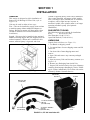
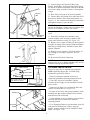
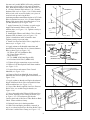
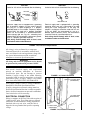
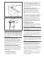
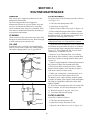
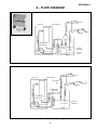
I-PF-151B
Installation, Setup
and Operation
INSTRUCTIONS
for
SUNNEN® HONING OIL FILTER UNIT
Model: PF-150
READ THE FOLLOWING INSTRUCTIONS THOROUGHLY AND CAREFULLY BEFORE UNPACKING,
INSPECTING, OR INSTALLING THE SUNNEN® PF-150 HONING OIL FILTER UNIT.
“SUNNEN AND THE SUNNEN LOGO ARE REGISTERED TRADEMARKS OF SUNNEN PRODUCTS COMPANY.”
SUNNEN ® PRODUCTS COMPANY • 7910 MANCHESTER AVENUE • ST. LOUIS, MO 63143, U.S.A. • PHONE: 314-781-2100
GENERAL INFORMATION
The Sunnen® equipment has been designed and engineered for a wide variety of parts within the capacity and limitation of the equipment. With proper care
and maintenance this equipment will give years of service.
READ THE FOLLOWING INSTRUCTIONS CAREFULLY AND THOROUGHLY BEFORE UNPACKING, INSPECTING, OR INSTALLING THIS EQUIPMENT.
IMPORTANT: Read any supplemental instructions BEFORE installing this equipment. These supplemental instructions give you important information to
assist you with the planning and installation of your Sunnen equipment.
Sunnen Technical Service Department is available to provide telephone assistance for installation, programming, & troubleshooting of your Sunnen
equipment. All support is available during normal business hours, 8:00 AM to 4:30 PM Central Time. Emergency breakdown support is available on a 24
hour / 7 day basis.
Review all literature provided with your Sunnen equipment. This literature provides valuable information for proper installation, operation, and maintenance
of your equipment. Troubleshooting information can also be found within the Instructions. If you cannot find what you need, call for technical support.
Where applicable, programming information for your Sunnen equipment is also included. Most answers can be found in the literature packaged with your
equipment.
Help us help you. When ordering parts, requesting information, or technical assistance about your equipment, please have the following
information available:
• Have ALL MANUALS on hand. The Customer Services Representative or Technician will refer to it.
• Have Model Number and Serial Number printed on your equipment Specification Nameplate.
• Where Applicable: Have Drive model and all nameplate data. Motor type, brand, and all nameplate data.
For Troubleshooting, additional information may be required:
• Power distribution information (type - delta, wye, power factor correction; other major switching devices used, voltage fluctuations)
• Installation Wiring (separation of power & control wire; wire type/class used, distance between drive and motor, grounding).
• Use of any optional devices/equipment between the Drive & motor (output chokes, etc.).
For fast service on your orders call:
Sunnen Automotive Customer Service toll free at: 1-800-772-2878
Sunnen Industrial Customer Service toll free at: 1-800-325-3670
Customers outside the USA, contact your local authorized Sunnen Distributor.
Additional information available at: http://www.sunnen.com or e-mail: [email protected]
NOTE: Sunnen reserves the right to change or revise specifications and product design in connection with any feature of our products contained herein.
Such changes do not entitle the buyer to corresponding changes, improvements, additions, or replacements for equipment, supplies or accessories
previously sold. Information contained herein is considered to be accurate based on available information at the time of printing. Should any discrepancy of
information arise, Sunnen recommends that user verify the discrepancy with Sunnen before proceeding.
ESD PREVENTION REVIEW
Let's review the basics of a sound static control system and its effective implementation. First, in the three step plan:
1.
Always ground yourself when handling sensitive components or assemblies.
2.
Always use a conductive or shielded container during storage or transportation. These materials create a Faraday
cage which will isolate the contents from static charges.
3.
Open ESD safe containers only at a static safe work station.
At the static safe work station, follow these procedures before beginning any work:
A.
Put on your wrist strap or foot grounding devices.
B.
Check all grounding cords to make sure they are properly connected to ground, ensuring the effective dissipation of static charges.
C.
Make sure that your work surface is clean and clear of unnecessary materials, particularly common plastics.
D.
Anti-static bubble wrap has been included for use at the machine when an ESD safe workstation is not available.
You are now properly grounded and ready to begin work. Following these few simple rules and using a little common sense will go a long
way toward helping you and your company in the battle against the hazards of static electricity. When you are working with ESD sensitive devices, make sure you:
GROUND
ISOLATE
NEUTRALIZE
ii
SUNNEN® LIMITED PRODUCT WARRANTY
Sunnen® Products Company and its subsidiaries (SPC) warrant that all new SPC honing machines, gaging equipment, tooling, and related equipment will
be free of defects in material and/or workmanship for a period of one year from the date of original shipment from SPC.
Upon prompt notification of a defect during the one-year period, SPC will repair, replace, or refund the purchase price, with respect to parts that prove to be
defective (as defined above). Any equipment or tooling which is found to be defective from improper use will be returned at the customer's cost or repaired
(if possible) at customer's request. Customer shall be charged current rates for all such repair.
Prior to returning any SPC product, an authorization (RMA#) and shipping instructions must be obtained from the Customer Service Department or items
sent to SPC will be returned to the customer.
Warranty Limitations and Exclusions This Warranty does not apply to the following:
• Normal maintenance items subject to wear and tear: (belts, fuses, filters, etc).
• Damages resulting from but not limited to:
› Shipment to the customer (for items delivered to customer or customer's agent F.O.B., Shipping Point)
› Incorrect installation including improper lifting, dropping and/or placement
› Incorrect electric power (beyond +/- 10% of rated voltage) including intermittent or random voltage spikes or drops
› Incorrect air supply volume and/or pressure and/or contaminated air supply
› Electromagnetic or radio frequency interference from surrounding equipment (EMI, RFI)
› Storm, lightning, flood or fire damage
› Failure to perform regular maintenance as outlined in SPC manuals
› Improper machine setup or operation causing a crash to occur
› Misapplication of the equipment
› Use of non-SPC machines, tooling, abrasive, fixturing, coolant, repair parts, or filtration
› Incorrect software installation and/or misuse
› Non-authorized customer installed electronics and/or software
› Customer modifications to SPC software
THE LIMITED WARRANTY DESCRIBED HEREIN IS EXPRESSLY IN LIEU OF ALL ANY OTHER WARRANTIES. SPC MAKES NO REPRESENTATION OR WARRANTY OF ANY
OTHER KIND, EXPRESS OR IMPLIED, WHETHER AS TO MERCHANTABILITY, FITNESS FOR A PARTICULAR PURPOSE OR ANY OTHER MATTER. SPC IS NOT
RESPONSIBLE FOR THE IMPROPER USE OF ANY OF ITS PRODUCTS. SPC SHALL NOT BE LIABLE FOR DIRECT, INDIRECT, INCIDENTAL, OR CONSEQUENTIAL
DAMAGES INCLUDING BUT NOT LIMITED TO: LOSS OF USE, REVENUE, OR PROFIT. SPC ASSUMES NO LIABILITY FOR PURCHASED ITEMS PRODUCED BY OTHER
MANUFACTURERS WHO EXTEND SEPARATE WARRANTIES. REGARDLESS OF ANY RIGHTS AFFORDED BY LAW TO BUYER, SPC's LIABILITY, IF ANY, FOR ANY AND
ALL CLAIMS FOR LOSS OR DAMAGES WITH RESPECT TO THE PRODUCTS, AND BUYER'S SOLE AND EXCLUSIVE REMEDY THEREFORE, SHALL IN ALL EVENTS BE
LIMITED IN AMOUNT TO THE PURCHASE PRICE OF THAT PORTION OF THE PRODUCTS WITH RESPECT TO WHICH A VALID CLAIM IS MADE.
Shipping Damages
Except in the case of F.O.B., Buyer's destination shipments, SPC will not be liable for any settlement claims for obvious and/or concealed shipping damages.
The customer bears the responsibility to unpack all shipments immediately and inspect for damage. When obvious and/or concealed damage is found, the
customer must immediately notify the carrier's agent to make an inspection and file a claim. The customer should retain the shipping container and packing
material.
SUNNEN® SOFTWARE LICENSE AGREEMENT
This document is a Legal Agreement between you, as user and licensee (Licensee), and Sunnen® Products Company (SPC) with respect to preprogrammed
software (Software) provided by SPC for use on SPC Equipment. By using the Software, you, as Licensee, agree to become bound by the terms of this
Agreement.
In consideration of payment of the license fee (License Fee) which is part of the price evidenced by your receipt (Receipt), SPC grants to you as Licensee
a non-exclusive right, without right to sub-license, to use the particular copy of the SPC Software licensed hereunder only on the particular equipment sold with
the Software. SPC reserves all rights including rights not otherwise expressly granted, and retain title and ownership to the Software including all subsequent copies or updates in any media. The Software and all accompanying written materials are covered by copyrights owned by SPC. If supplied on
removable media (floppy disk), you, as Licensee, may copy the Software only for back up purposes; or you may request that SPC copy the Software for you
for the same purposes. All other copying of the Software or of the accompanying written materials is expressly forbidden and is in violation of the Agreement.
The Software and accompanying written materials (including the user's manual, if any) are provided in an "as is" condition without warranty of any kind
including the implied warranties of merchantability and fitness for a particular purpose, even if SPC has been advised of this purpose. SPC specifically does
not warrant that it will be liable as a result of the operation of the Software for any direct, indirect, consequential or accidental damages arising out of the
use of or inability to use such product even if SPC has been advised of the possibility of such use. It is recognized that some states do not allow the exclusion or limitation of liability for consequential or accidental damages and to the extent this is true, the above limitations may not apply.
Any alteration or reverse engineering of the software is expressly forbidden and is in violation of this agreement.
SPC reserves the right to update the software covered by this agreement at any time without prior notice and any such updates are covered by this
agreement.
iii
SAFETY INSTRUCTIONS
READ FIRST
This machine, like any machine tool, may be dangerous if used improperly. Please read all
warnings and instructions before attempting to use this machine.1
DO NOT remove or defeat any safety device.
Always wear eye protection when operating this machine.
DO NOT attempt any repair or maintenance procedure beyond those described in this book.
Contact your Sunnen Service Representative for repairs not covered in this book.
Indicates CE version ONLY.
1
DO NOT touch electrical components until main input power has been turned off and CHARGE lamps are
extinguished. WARNING: The capacitors are still charged and can be quite dangerous.
INTRODUCTION
Sunnen PF-150 Honing Oil Filter Unit is designed to filter grit and metal particles from coolant supply on
following model of Sunnen Precision Honing Machines:
LBB-1660
MBB-1660
MBB-1650*
MBB-1690*
MBB-1670*
MBH-2500*
MBB-1680*
MBH-2570*
MBH-2580*
*Out of Production
Unit is a 100% filter in that it filters all of coolant that passes through it; none is bypassed unless you
intentionally bypass it. In operation, unit's pump sucks dirty coolant from machine reservoir and pushes
this dirty coolant through a 5-micron paper filter element. Clean filtered coolant is then returned to
machine.
Unit pumps an oversupply of filtered coolant to machine. This oversupply of coolant is bled off to machine
reservoir by overflowing receiving bucket or by action of optional low-pressure relief valve (MBB-1620
Pump Bypass Kit), depending upon which method of installation is employed.
As filter canister fills with sludge being removed from coolant, an ample supply of filtered coolant
continues to be supplied to machine. Over 75 cubic inches (1.2 liters) of sludge can accumulate in canister
without interfering with filtering operation. When filter element clogs, coolant supply to machine is shut
off. 5-micron filter element can be changed easily in a few minutes, restoring flow filtered coolant.
iv
TABLE OF CONTENTS
Page
General Information . . . . . . . . . . . . . . . . . . . . . . . . . . . . . . . . . . . . . . . . . . . . . . . . . . . . . . . . . . . . . . . . . . . . . . ii
ESD Prevention Review . . . . . . . . . . . . . . . . . . . . . . . . . . . . . . . . . . . . . . . . . . . . . . . . . . . . . . . . . . . . . . . . . . . ii
Sunnen® Limited Product Warranty . . . . . . . . . . . . . . . . . . . . . . . . . . . . . . . . . . . . . . . . . . . . . . . . . . . . . . . . . . iii
Sunnen® Software License Agreement . . . . . . . . . . . . . . . . . . . . . . . . . . . . . . . . . . . . . . . . . . . . . . . . . . . . . . . iii
Introduction . . . . . . . . . . . . . . . . . . . . . . . . . . . . . . . . . . . . . . . . . . . . . . . . . . . . . . . . . . . . . . . . . . . . . . . . . . . . iv
Safety Instructions . . . . . . . . . . . . . . . . . . . . . . . . . . . . . . . . . . . . . . . . . . . . . . . . . . . . . . . . . . . . . . . . . . . . . . . iv
Table Of Contents . . . . . . . . . . . . . . . . . . . . . . . . . . . . . . . . . . . . . . . . . . . . . . . . . . . . . . . . . . . . . . . . . . . . . . . v
General Information & Specifications . . . . . . . . . . . . . . . . . . . . . . . . . . . . . . . . . . . . . . . . . . . . . . . . . . . . . . . . vi
INSTALLATION
General . . . . . . . . . . . . . . . . . . . . . . . . . . . . . . . . . . . . . . . . . . . . . . . . . . . . . . . . . . . . . . . . . . . . . . . . . . . . . . . . . .
Suggested Toolin . . . . . . . . . . . . . . . . . . . . . . . . . . . . . . . . . . . . . . . . . . . . . . . . . . . . . . . . . . . . . . . . . . . . . . . . . .
Unpacking . . . . . . . . . . . . . . . . . . . . . . . . . . . . . . . . . . . . . . . . . . . . . . . . . . . . . . . . . . . . . . . . . . . . . . . . . . . . . . . .
Installation . . . . . . . . . . . . . . . . . . . . . . . . . . . . . . . . . . . . . . . . . . . . . . . . . . . . . . . . . . . . . . . . . . . . . . . . . . . . . . .
Optinal Installation . . . . . . . . . . . . . . . . . . . . . . . . . . . . . . . . . . . . . . . . . . . . . . . . . . . . . . . . . . . . . . . . . . . . . . . . .
Electrical Requirements . . . . . . . . . . . . . . . . . . . . . . . . . . . . . . . . . . . . . . . . . . . . . . . . . . . . . . . . . . . . . . . . . . . . .
Electrical Connections . . . . . . . . . . . . . . . . . . . . . . . . . . . . . . . . . . . . . . . . . . . . . . . . . . . . . . . . . . . . . . . . . . . . . .
Operational Check . . . . . . . . . . . . . . . . . . . . . . . . . . . . . . . . . . . . . . . . . . . . . . . . . . . . . . . . . . . . . . . . . . . . . . . . .
1
1
1
2
3
6
6
7
PREPARING FOR OPERATION
General . . . . . . . . . . . . . . . . . . . . . . . . . . . . . . . . . . . . . . . . . . . . . . . . . . . . . . . . . . . . . . . . . . . . . . . . . . . . . . . . . . 9
Major Components. . . . . . . . . . . . . . . . . . . . . . . . . . . . . . . . . . . . . . . . . . . . . . . . . . . . . . . . . . . . . . . . . . . . . . . . . 9
Safety Symbols . . . . . . . . . . . . . . . . . . . . . . . . . . . . . . . . . . . . . . . . . . . . . . . . . . . . . . . . . . . . . . . . . . . . . . . . . . . . 9
SETUP & OPERATION
General . . . . . . . . . . . . . . . . . . . . . . . . . . . . . . . . . . . . . . . . . . . . . . . . . . . . . . . . . . . . . . . . . . . . . . . . . . . . . . . . . 11
Safety Precautions . . . . . . . . . . . . . . . . . . . . . . . . . . . . . . . . . . . . . . . . . . . . . . . . . . . . . . . . . . . . . . . . . . . . . . . . 11
Operating Hints . . . . . . . . . . . . . . . . . . . . . . . . . . . . . . . . . . . . . . . . . . . . . . . . . . . . . . . . . . . . . . . . . . . . . . . . . . . 11
Start-Up of Honing Operation . . . . . . . . . . . . . . . . . . . . . . . . . . . . . . . . . . . . . . . . . . . . . . . . . . . . . . . . . . . . . . . 12
ROUTINE MAINTENANCE
General . . . . . . . . . . . . . . . . . . . . . . . . . . . . . . . . . . . . . . . . . . . . . . . . . . . . . . . . . . . . . . . . . . . . . . . . . . . . . . . . .
Cleaning . . . . . . . . . . . . . . . . . . . . . . . . . . . . . . . . . . . . . . . . . . . . . . . . . . . . . . . . . . . . . . . . . . . . . . . . . . . . . . . .
Coolant Line . . . . . . . . . . . . . . . . . . . . . . . . . . . . . . . . . . . . . . . . . . . . . . . . . . . . . . . . . . . . . . . . . . . . . . . . . . . . .
Filter Element . . . . . . . . . . . . . . . . . . . . . . . . . . . . . . . . . . . . . . . . . . . . . . . . . . . . . . . . . . . . . . . . . . . . . . . . . . . .
Filter Canister . . . . . . . . . . . . . . . . . . . . . . . . . . . . . . . . . . . . . . . . . . . . . . . . . . . . . . . . . . . . . . . . . . . . . . . . . . . .
Low Pressure Relief Valve (Opt.) . . . . . . . . . . . . . . . . . . . . . . . . . . . . . . . . . . . . . . . . . . . . . . . . . . . . . . . . . . . . .
Pump Seal . . . . . . . . . . . . . . . . . . . . . . . . . . . . . . . . . . . . . . . . . . . . . . . . . . . . . . . . . . . . . . . . . . . . . . . . . . . . . . .
13
13
13
13
13
14
15
TROUBLESHOOTING
General . . . . . . . . . . . . . . . . . . . . . . . . . . . . . . . . . . . . . . . . . . . . . . . . . . . . . . . . . . . . . . . . . . . . . . . . . . . . . . . . . 17
Operational Troubleshooting . . . . . . . . . . . . . . . . . . . . . . . . . . . . . . . . . . . . . . . . . . . . . . . . . . . . . . . . . . . . . . . . . 17
APPENDIXES
A - Flow Diagram
“SUNNEN AND THE SUNNEN LOGO ARE REGISTERED TRADEMARKS OF SUNNEN PRODUCTS COMPANY.”
© Copyright 2003 by Sunnen® Products Company • Printed in U.S.A.
v
GENERAL INFORMATION & SPECIFICATIONS
Sunnen® Honing Oil Filter Unit - Model PF-150
FILTER CAPACITY:
SLUDGE CAPACITY:
FLOW CAPACITY:
COOLANT CAPACITY:
FLOOR SPACE:
(w/Support Tube)
SHIPPING WEIGHT:
PUMP MOTOR:
ELECTRICAL REQUIREMENTS:
Paper, 4550 sq/in (29,3 sg/cm)
75 cin (1230 ccm)
1.5 gal/min @ 25 lbs/in2 (5,7 L/min @ 1,7 bars)
3.5 gal. 913,3 L)
30 W x 15 D x 33 H in.
(762 x 381 x 838 mm)
200 lbs (90 kg)
1/2 hp (0,37 kW)
115 V, 60 Hz, 1-Ph; 230 V, 50 Hz, 1-Ph
39 in.
(991 mm)
15 in.
(381 mm)
LEFT
33 in.
(838 mm)
48 in.
(1219 mm)
FRONT
30 in.
(762 mm)
FIGURE 1-A, Floor Plan Layout (System Configuration)
vi
RIGHT
SECTION 1 INSTALLATION
GENERAL
This section is designed to aid in installation of
Sunnen PF-150 Honing Oil Filter Unit (refer to
Figure 1-A).
Unit may be used in either of two ways:
First - Unit can be installed to supply clean coolant
to machine pump without additional adapters or
fittings. Belt-driven pumps will then supply clean
coolant to machine's flow control manifold. (See
Installation.)
Second - Unit may also be installed using optional
MBB-1620 Pump Bypass Kit (not supplied, must be
ordered separately). When unit is installed in this
manner, machine pump is bypassed and clean
FIGURE 1-1, Unpacking
coolant is supplied directly from Unit to machine's
flow control manifold. advantages of this installation is a stronger, more constant flow of coolant to
workpiece; and a slight increase in power at
machine's spindle, since spindle motor is no longer
operating machine's pump. (See Optional
Installation.)
SUGGESTED TOOLING
The following tools are required for installation:
Knife
Screw Driver (std.)
Hex Wrenches (1/8 & 5/32 in.)
Open End Wrench (7/16 & 9/16 in.)
UNPACKING
Unpack Unit as follows (see Figure 1-1):
1. Cut Bands on shipping carton.
2. Cut around base of outer shipping carton and lift
carton off.
3. Cut down side of inner shipping carton and
remove.
4. Open Unit and remove any contents packaged
inside unit.
5. Open Accessory Pack and inventory contents (see
Figure 1-2).
6. Remove any Packaging from inside Unit.
7. Inspect Unit and Accessories for signs of damage
resulting from improper handling by carrier. If damage is evident, immediately file a claim with carrier
and notify Sunnen Customer Service.
RECEIVING
BUCKET
CLAMPS
RETURN LINE
(PLAIN END)
1/2” NIPPLE, ELBOW &
COLLAR
(SUCTION LINE)
SUCTION LINE
(W/STRAINER)
3/8” NIPPLE, ELBOW &
COLLAR
(RETURN LINE)
FIGURE 1-2, PF-165 Installation Kit
KNOCKOUT
PLUG
INSTALLATION
PUMP BELT
To install Unit on one of Sunnen Precision Honing
Machines, proceed as follows:
SCREW(4)
1. Drain coolant from machine reservoir as
instructed in machine operating instruction book.
2. Turn OFF all power to machine. Unplug electrical
power supply cord or disconnect at main power source.
3. Remove Left Rear Cover of machine base and
remove Oil Pump Belt (see Figure 1-3).
LEFT REAR
COVER
4. Locate coolant line (tube and spring assembly)
inside machine base that connects oil pump to Flow
control manifold, and disconnect. Do not discard.
5. Clean machine reservoir. Remove reservoir from
machine and clean as instructed in machine
operating manual.
FIGURE 1-3, Oil Pump
6. Attach Filtered Oil Receiving Bucket to pump
support (see Figure 1-4). Pump Support must
engage notches in front and rear walls of Bucket.
Knockout Plug should face left side of reservoir, as
seen when facing front of machine. DO NOT
remove Knockout Plug.
PUMP
SUPPORT
7. Place reservoir back in machine and reconnect
oil line to Flow control manifold.
CLAMPS
8. Replace oil pump belt and adjust tension as
instructed in machine operating instruction book.
RECEIVING
BUCKET
9. If so Equipped: Remove two knockouts from left
side panel of machine base. Elbows and pipe
nipples supplied with Kit will be installed in these
Holes (see Figure 1-5).
On some early model MBB-1650 honing machines,
holes were not provided in side panel of machine
base. With these machines, locate and drill one 7/8
in. (22 mm) diameter Hole and one ¾ in. (19 mm)
diameter Hole (refer to Figure 1-5). If sheet metal
drills or hole saws are not available, use a piece of
wood to back up area being drilled.
On honing machines manufactured prior to 1979, both
Holes in machine base were ¾ in. (19 mm) diameter.
Enlarge Hole nearest back of machine base to 7/8 in.
(22 mm) diameter (refer to Figure 1-5).
KNOCKOUT
PLUG
FIGURE 1-4, Bucket
5 in.
(127mm)
3 in.
(76mm)
10. Apply Permatex No. 2 Sealant, or equal to pipe
nipples and assemble Elbows with Collars to
machine base (refer to Figure 1-5). Tighten securely
to prevent leaks.
2 in.
(51mm)
1/2” ELBOW (BOTH SIDES)
3/8” ELBOW (BOTH SIDES)
HOLE
7/8in. (22mm)
11. Connect Dirty Oil Suction Line (with strainer)
to rear elbow installed in step 10 (see Figures 1-5 &
1-6). Use sealant on threaded connection and
tighten securely to prevent leaks.
HOLE
3/4 in. (19mm)
12. Connect Filtered Oil Return Line (plain end) to
forward elbow installed in step 10 (see Figures 1-5
& 1-6). Use sealant on threaded connection and
tighten securely to prevent leaks.
FIGURE 1-5, Elbows
2
COLLAR
(INSIDE UNIT)
13. Loosen clamps on Filtered Oil Receiving
Bucket. Install Dirty Oil Suction Line under clamp
on outside of Bucket; and install Filtered Oil Return
Line under clamp on inside of bucket. Then tighten
clamps.
INSIDE UNIT
RETURN
LINE
14. Place Unit at left side or in back of machine.
15. Connect Dirty Oil Suction Line and Filtered Oil
Return Line between Filter Unit and machine (see
Figure 1-7). Use sealant on all threaded connections
and tighten securely to prevent leaks.
NOTE: These oil lines are attached to filter unit
cabinet for shipment. Connect lines to machine first,
then to swivel adapter on filter unit cabinet.
OUTSIDE
UNIT
16 Open top to Unit and remove cover clamp and
cover.
SUCTION
LINE
RECEIVING
BUCKET
17. Insert filter element into container, rotate
element slightly while inserting to make it slide
down center post more easily (see Figure 1-8).
FIGURE 1-6, Coolant Lines
18. Replace cover, center carefully on rubber gasket
to assure no leakage. Then replace Clamp and tighten
Hex Bolt in Clamp Halves until halves meet, then
tighten T-Handle.
19. Hookup is now complete. Check for proper oil
line routing by referring to Appendix B, Flow
Diagram.
RETURN
LINE
SUCTION
LINE
20. Proceed to Electrical Connection.
NOTE: Coolant will be replaced in honing machine
and left rear cover of honing machine base will be
reinstalled during Operational Check.
FIGURE 1-7, Coolant Lines
T-HANDLE
FILTER
ELEMENT
OPTIONAL INSTALLATION
Filter Unit may also be installed using Optional
MBB-1620 Pump Bypass Kit. To install using
optional Kit, proceed as follows:
COVER
AIR VENT
CLAMP HALVES
1. Drain coolant from machine reservoir as
instructed in machine operating instruction book.
NOTE: TIGHTEN HEX BOLT
UNTIL CLAMP HALVES MEET,
THEN TIGHTEN T-HANDLE.
2. Turn OFF all power to machine. Unplug
electrical power supply cord or disconnect at main
power source.
FIGURE 1-8, Filter Element
3. Remove Left Rear Cover of machine base and
remove Oil Pump Belt (see Figure 1-9).
PUMP
BELT
4. Locate oil line (tube and spring assembly) inside
machine base that connects pump to Flow control
manifold and. Do not discard.
SCREW(4)
5. Clean machine reservoir. Remove reservoir from
machine and clean as instructed in machine
operating manual.
6. If so Equipped: Remove two knockouts from left
side panel of machine base. Elbows and pipe
nipples supplied with Kit will be installed in these
Holes (see Figure 1-10).
LEFT REAR
COVER
FIGURE 1-9, Pump
3
On some early model MBB-1650 honing machines,
holes were not provided in side panel of machine
base. With these machines, locate and drill one 7/8
in. (22 mm) diameter Hole and one ¾ in. (19 mm)
diameter Hole (refer to Figure 1-10). If sheet metal
drills or hole saws are not available, use a piece of
wood to back up area being drilled.
On honing machines manufactured prior to 1979, both
Holes in machine base were ¾ in. (19 mm) diameter.
Enlarge Hole nearest back of machine base to 7/8 in.
(22 mm) diameter (refer to Figure 1-10).
5 in. (127mm)
2 in. (51mm)
3 in. (76mm)
7. Apply Permatex No. 2 Sealant, or equal to pipe
nipples and assemble Elbows with Collars to
machine base (see Figure 1-11). Tighten securely to
prevent leaks.
HOLE
7/8in. (22mm)
KNOCKOUT
8. Install Nipple, Elbows, and Collar in 7/8 in. (22 mm)
diameter Hole as shown (refer to Figure 1-11).
Collar is installed on inside of machine base.
Tighten securely to prevent leaks.
HOLE
3/4 in. (19mm)
FIGURE 1-10, Knockouts
9. Install Low-Pressure Relief Valve (supplied) as
shown (refer to Figure 1-11).
LOW PRESSURE
RELIEF VALVE
10. Apply sealant to all threaded connections and
install following items thru 3/4 in. (19-mm) diameter
Hole as shown (refer to Figure 1-11):
3/8" Elbow (PF-165 Installation Kit)
3/8" Close Nipple (PF-165)
Collar (PF-165)
3/8" Tee (MBB-1620 Pump Bypass Kit)
Low-Pressure Relief Valve (MBB-1620)
(FRONT
OF UNIT)
3/8” TEE
3/8” ELBOW
(OUTSIDE
OF UNIT)
COLLAR
1/2”
ELBOW
(INSIDE OF UNT)
11. Tighten all pipe connections to prevent leaks.
FIGURE 1-11, Fittings
12. Remove Left Rear Splash Guard from machine
(see Figure 1-12).
LEFT REAR
SLASH GUARD
13. Loosen Screw and remove Flow Control
Manifold (see Figure 1-13).
14. Unscrew Pipe from Manifold; then reinstall
Manifold and left rear splash guard on machine (see
Figure 1-14).
15. Apply sealant to threads on Nipple; then thread
Nipple with Back Check Valve into manifold from
inside machine base (see Figure 1-15).
FIGURE 1-12, Guard
16. Screw Hose Barb (supplied) into Low-Pressure
Relief Valve, use sealant on pipe threads (see
Figure 1-16).
17. Screw threaded end of Filtered Oil Return Line
into Center Opening of Tee Fitting as shown (refer
to Figure 1-16). Use sealant on pipe threads.
Connect plain end of this line to Hose Barb on Back
Check. Fasten with hose clamp.
FLOW CONTROL
MANIFOLD
18. Reinstall reservoir in honing machine.
19. Slide Tube and Spring Assembly, removed in
step 4, over hose barb on Low-Pressure Relief Valve
and secure it with a Hose Clamp (see Figure 1-17).
SCREW
FIGURE 1-13, Manifold
4
NOTE: Make sure free end of Tube and Spring
Assembly is in reservoir. Otherwise, coolant will be
pumped onto floor.
20. Place Filter Unit at left side or in back of
machine.
FLOW CONTROL
MANIFOLD
21. Connect Dirty Oil Suction Line and Filtered Oil
Return Line between Filter Unit and machine (see
Figure 1-18). Use sealant on all threaded connections
and tighten securely to prevent leaks.
NOTE: These oil lines are attached to filter unit
cabinet for shipment. Connect lines to machine first,
then to swivel adapter on filter unit cabinet.
PIPE
22 Open top to Unit and remove cover clamp and
cover.
FIGURE 1-14, Manifold
23. Insert filter element into container, rotate
element slightly while inserting to make it slide
down center post more easily (see Figure 1-19).
NIPPLE
24. Replace cover, center carefully on rubber gasket
to assure no leakage. Then replace cover clamp.
25. Hookup is now complete. Check for proper oil line
routing by referring to Appendix B, Flow Diagram.
26. Proceed to Electrical Connection.
NOTE: Coolant will be replaced in honing machine
and left rear cover of honing machine base will be
reinstalled during Operational Check.
BACK CHECK
VALVE
FIGURE 1-15, Back Check Valve
CENTER OPENING
OF TEE FITTING
RETURN LINE (TO
BACK CHECK)
RETURN
LINE
ELBOW
SUCTION
LINE
HOSE BARB
LOW PRESSURE
RELIEF VALVE
SUCTION LINE (FROM
RESERVOIR)
FIGURE 1-16, Low-Pressure Relief Valve
FIGURE 1-18, Coolant Line
HOSE
CLAMP
LOW PRESSURE
RELIEF VALVE
FILTER
ELEMENT
TUBE & SPRING
(TO RESERVOIR)
FIGURE 1-19, Filter Element
FIGURE 1-17, Coolant Line
5
115V UNIT
Outlet for 115 volt unit should look like the following.
230V UNIT
Outlet for 230 volt unit should look like the following.
ADAPTER
GROUNDING
SCREW
PROPER
OUTLET
GROUNDING PIN
GROUNDING PIN
Electrical supply cord is equipped with a grounding
pin. A temporary adapter, may be used to connect
this plug to a 2-pole receptacle, if a properly
grounded outlet is not available. Temporary adapter
should ONLY be used until a properly grounded
outlet can be installed by a qualified electrician.
Green-colored rigid ear, lug, etc., extending from
adapter MUST be connected to a permanent ground,
such as a properly grounded outlet box.
Unit wiring should comply with all local, state,
and federal codes and ordinances.
Electrical supply cord is equipped with a grounding
type plug. Make sure unit is connected to an outlet
having the same configuration as the plug. No
adapter is available or should be used with this unit.
If the unit MUST be reconnected for use on a
different type of electrical circuit, the reconnection
should be made by a qualified electrician.
Unit wiring should comply with all local, state,
and federal codes and ordinances.
FIGURE 1-20, Electrical Requirements
ELECTRICAL REQUIREMENTS
All wiring is to be performed by a competent,
Licensed Electrician in accordance with all local,
state, and federal codes and regulations; along with
any special information provided on machine
nameplate or electrical specification plate.
WARNING
All wiring and electrical equipment service should
be performed by authorized personnel ONLY.
CONNECTION
(IN BOTTOM)
CAUTION
Note model electrical supply cord requirement
printed on machine nameplate or electrical
specification plate. Do not attempt to connect
machine if supply voltage is not within following
acceptable limits as noted on nameplate or electrical
specification plate. If supply voltage is not within
these limits MACHINE WILL BE DAMAGED.
FIGURE 1-21, Switch Enclosure
CUT HOLE HERE
(PERMISSIBLE)
Verify supply voltage is same as voltage on Machine
Nameplate or Electrical Specifications Plate.
If supply voltage does not match voltage stated on
Electrical Specification Plate but is within acceptable
limits, electrical connection can proceed but Machine
Conversion below will be necessary.
CUT HOLE HERE
(PERMISSIBLE)
ELECTRICAL CONNECTION
Wiring is complete on all Filter Units with exception of
3 phase non-JIC units. These filter units are shipped
with starter switch unmounted. Wiring diagrams are
furnished with every unit. Also, each filter unit is
shipped with a tag attached that specifies operating
voltage.
CUT HOLE HERE
(PREFERRED)
FIGURE 1-22, Electrical Enclosure
6
3-phase supply (not furnished) must be brought into
switch enclosure through one of knockouts
provided. Locally approved line disconnect switch
and over current protection (if required) are to be
provided by user. When wiring is complete, reinstall
switch enclosure cover.
TOTAL VOLUME
CONTROL VALVE
208/230/460 V, 60 Hz, 3 Ph JIC Units
3-phase supply (not furnished) must be brought into
control enclosure and connected according to
appropriate wiring diagram. user must provide an
entrance hole for power cord. To preserve oil
tightness of enclosure, all fittings must be oil-tight
type.
Cut or punch Hole for electrical power supply near
bottom corner of electrical control box, as shown
(see Figure 1-22). It is preferable to cut Hole in bottom of box to assure that oil does not enter box
even if fittings are not perfectly tight. Do not cut
Hole other than where shown components inside
box will prevent you from making proper connections. Make sure fittings are tight to prevent oil or
chips from entering box.
FIGURE 1-23, Total Volume Control Valve
AIR VENT
FILTER
COVER
COVER
CLAMP
OPERATIONAL CHECK
1. Fill machine reservoir with Sunnen Industrial
Coolant. Pull out movable tray to its fully extended
position and pour coolant into tray.
CAUTION
Make filter unit installation checkout with honing
machine turned off.
FIGURE 1-24, Air Vent
2. Turn Total Volume Control Valve on honing
machine clockwise to off position (see Figure 1-23).
NOTE: The electrical data plate attached to filter
unit provides helpful data including maximum
current requirements. Wiring diagram number for
unit is stamped on this plate. Should additional
copies be needed, specify DIAGRAM NUMBER
with your request.
3. Check pump for correct rotation by momentarily
switching on unit and observing shaft between
pump and motor. Facing pump end, shaft should be
turning counterclockwise.
NOTE: For Units which operate on 3 phase power, if
filter pump is rotating backwards, remove power
from power cord supplying filter unit and reverse any
two of line connections at terminals L1, L2, or L3 on
switch.
115/230 V, 60 Hz, Single Phase Units
These filter units are supplied with an electrical
cord and plug that is rated 250 volts, 15 amps. Cord
and plug are generally considered as acceptable
disconnecting means. If required by local code,
disconnect switch, fuses, or circuit breakers must be
provided by user (see Figure 1-20).
For Units for use on single-phase power are
connected for correct rotation when manufactured. If
reversal of pump rotation is ever necessary, follow
directions on pump motor terminal box cover.
208/230/460 V, 60 Hz, 3 Ph & 220/380/440 V, 50
Hz, 3 Ph Manual Start Units (non-JIC)
Open switch enclosure cover and, with hardware
provided, mount starter switch on filter unit cabinet.
Assemble cable connector to switch enclosure as
shown (see Figure 1-21). Wire cable conductors to
switch as follows:
Red conductor to Terminal TI;
White conductor to Terminal T2;
Black conductor to Terminal T3;
Green conductor to Ground Lug.
4. Open Air Vent in Filter Cover and start filter
pump. indicator light on filter unit will indicate that
power is on (see Figure 1-24). As coolant fills filter
container, air will escape through Air Vent.
5. When coolant appears at Air Vent (usually one to
two minutes), close vent.
If filter unit fails to pump after being hooked up
correctly, manually prime filter pump at Suction
Line Fitting as follows:
7
• Turn filter unit off.
• Loosen Dirty Oil Suction Line Fitting on filter
unit cabinet at location as shown (see Figure 1-25).
• Remove suction line from this fitting only and fill
it with honing oil.
• Reconnect dirty oil suction line. Tighten securely
to prevent suction leaks and turn filter unit on.
SUCTION LINE
FITTING
6. After air vent is closed, filtered coolant will be
flowing back to honing machine reservoir. If
Receiving Bucket is used:
• Filtered coolant will be flowing into Receiving
Bucket (see Figure 1-26). To get coolant to workpiece, start honing machine motor and adjust flow
control valves on flow control manifold in usual
manner.
• Unit pumps more filtered oil into Receiving
Bucket than honing machine uses. This excess
filtered coolant is returned to reservoir through
Overflow Holes.
FIGURE 1-25, Suction Line
OVERFLOW
HOLES
If Pump Bypass Kit is used• Check for proper flow of filtered coolant to
reservoir by slowly raising free end of Tube and
Spring Assembly (see Figure 1-27). Since Flow
control manifold has been turned off, full flow of
filtered coolant from filter unit is being returned to
reservoir through Tube and Spring Assembly.
• To get coolant to work-piece, adjust flow control
valves on Flow control manifold in usual manner. It
is not necessary to operate honing machine motor to
apply coolant to workpiece when Pump Bypass Kit
is used.
• Check for proper Low-Pressure Relief Valve
adjustment. Adjust flow control valves on Flow
control manifold as appropriate. You should be able
to "overshoot" workpiece with 3 coolant streams
with all oil jets operating at same time.
• Low-Pressure Relief Valve may be adjusted for
more or less coolant pressure by turning Adjusting
Screw on end of Low-Pressure Relief Valve. First,
loosen Locking Nut, then tighten Adjusting Screw
to increase oil pressure or loosen Adjusting Screw
to decrease oil pressure. Retighten Locking Nut
when adjustment is satisfactory.
RECEIVING
BUCKET
FIGURE 1-26, Bucket
HOSE
CLAMP
LOCKING
NUT
ADJUSTING
SCREW
LOW PRESSURE
RELIEF VALVE
TUBE & SPRING
ASSEMBLY
FIGURE 1-27, Bypass
CAUTION
Unit also has a High-Pressure Relief Valve on the
pressure side of pump to prevent crushing of filter
elements. This High-Pressure Relief Valve is located
adjacent to filter pump (see Figure 1-28). Valve is a
factory sealed adjustment. DO NOT ATTEMPT TO
READJUST.
FIGURE 1-28, High Pressure Relief Valve
7. Examine all hose and pipe fittings for any oil
leaks. Retighten if necessary.
8. Reinstall left rear panel on honing machine base.
8
SECTION 2 PREPARING FOR OPERATION
GENERAL
6. FILTER CANISTER.
7. PUMP
8. HIGH PRESSURE RELIEF VALVE
9. PUMP MOTOR
10. STORAGE STRAPS
11. FUSE - Pump Motor
This section should be consulted when preparing
Unit for operation.
MAJOR COMPONENTS.
For location of major controls and components refer
to Figures 2-1.
1. FILTER ELEMENT
2. COVER CLAMP
3. AIR VENT
4. PILOT LIGHT - indicate when Pump is turned ON.
5. START/STOP SWITCH - Controls electrical
power to Pump.
SAFETY SYMBOLS
For a description of safety symbols used on this
machine refer to Table 2-1 on page 10.
STORAGE
STRAPS
AIR VENT
HIGH PRESSURE
RELIEF VALVE
PILOT
LIGHT
SWITCH
PUMP
MOTOR
FILTER
PUMP
FILTER ELEMENT
(NOT SHOWN)
FILTER
CANISTER
FIGURE 2-1, Honing Oil Filter Unit
9
TABLE 2-1, Safety Symbols
SYMBOL
DESCRIPTION
FUNCTION
Warning Label
Warns that an electrical hazard exists.
Label
Designates this machine is “CE” compliance.
Warning Strip
Warns that a physical hazard exits, and that proper precautions should be taken.
Warning Label
(Safety Glasses)
Warns that safety glasses should be worn at all times when
operating this machine.
10
SECTION 3 SETUP & OPERATION
GENERAL
operation is dusty.
• Use workholding fixture, clamp or vise to hold
work. DO NOT use your hands to hold workpiece.
• Don't overreach; keep proper footing and balance
at all times.
• Inspect tools before using for cracks, burrs or bent
parts that might effect operation.
• Keep tools sharp, clean and in their proper storage
compartments to maintain them in proper working
condition and to prolong tool life. Follow
instructions for lubricating and maintaining tools.
• Unplug Unit when preforming service not
requiring power.
• Reduce risk of unintentional starting; ensure
switch is in OFF position before plugging in.
• Before using a tool that has been damaged should
be properly repaired or replaced before using.
Before using a guard or part that has been damaged;
check to determine that it will operate properly and
perform its intended function; check for alignment
of moving parts, binding of moving parts, breakage
of parts, mounting, and any other conditions that
may affect its operation.
• Never leave tool running unattended. Turn power
off and don't leave until it comes to a complete stop.
• When lifting workpiece or tooling use proper
lifting procedures.
• Keep hands clear of all moving parts.
This section describes step-by-step operating procedures for use of Power Unit in Valve Guide
Reconditioning.
SAFETY PRECAUTIONS
following safety precautions are recommended by
Underwriters Laboratories, Inc. and should be
followed to ensure maximum safety of personnel
while working on or around Honing Stand.
• Ensure all guards are in place and in working
order.
• Remove keys and adjusting wrenches before
turning ON unit.
• Keep work area clean. Cluttered areas and benches
invite accidents. Keep area around Unit free of
paper, oil, water and all other debris at all times.
• Don't use power tools in a damp or wet locations,
or expose them to rain. Keep work area well
lighted.
• All visitors should be kept safe distance from
work area.
• Make workshop kid proof with pad-locks, master
switches, or by removing starter keys.
• DO NOT force tools; tools will do a better and
safer job when operated at rate for which they were
designed.
• Use right tool; don't use a tool to do a job for
which it was not designed.
• Wear proper apparel. DO NOT wear loose clothing
or jewelry while working on or around Unit.
Non-slip footwear and protective hair covering to
contain long hair is recommended.
• Wear proper Safety items such as, safety glasses,
and other personal safety equipment as necessary or
required. Also use face or dust mask if cutting
OPERATING HINTS
The Filter Unit uses Sunnen PF-105 Filter Element.
From time to time, it is necessary to replace filter
element as it becomes loaded with. chips and
abrasive particles being filtered from honing oil.
Additional filter elements are available in cartons of
four elements, reorder by part number PF-105-4.
Replacement filter elements are shipped in
polyethylene bags to prevent damage from moisture
and dirt. Do not open polyethylene bag until filter
element is to be used. Space is provided in filter
unit cabinet for storage of up to four filter elements
(see Figure 3-1).
STORAGE
STRAPS
When To Change Filter Element
1. If Filtered Oil Receiving Bucket is used:
When filter element is new, filter pump supplies
more clean oil into filtered oil-receiving bucket than
machine uses. excess clean coolant overflows into
reservoir. As filter element fills with chips and
FIGURE 3-1, Filter Storage
11
abrasive particles, flow of clean oil decreases, as
does overflow into reservoir. This process continues
until amount of clean oil supplied to filtered oil
receiving bucket becomes less than amount of oil
pumped by honing machine pump. At this point, too
little oil is supplied to workpiece or flow of oil to
workpiece is interrupted frequently, and filter
element should be replaced.
COOLANT ENTERS WORKPIECE
PARALLEL TO MANDREL
2. If Pump Bypass Kit is used:
When all four valves on Flow control manifold at
honing machine are wide open and coolant supplied
to workpiece is not sufficient, replace filter element.
FIGURE 3-2, Coolant
START-UP OF HONING OPERATION
Operation When Low On Coolant
If machine is low on Coolant, order more Sunnen
Industrial Honing Oil or Water-Based Coolant. DO
NOT add kerosene, cutting fluids, or any other fluid
to the coolant that's left - coolant will be ruined &
machine maybe damaged. If you must operate
machine before you receive your new coolant, place
a large piece of metal in the reservoir to raise level
above filter unit pump intake - but remember that
this is a temporary solution and remove the piece of
metal when you refill reservoir. You may also
remove the sediment tray temporarily.
1. Point coolant nozzles downward or turn off
coolant at machine's Flow Control Manifold.
2. Turn on both machine and Filter Unit. Indicator
light on filter unit will indicate that power is on.
CAUTION
If your machine uses receiving bucket in machine
reservoir and you do not turn the Filter Unit on, this
receiving bucket will be pumped dry in 30 seconds
and coolant will no longer be supplied to workpiece
If your machine uses the pump bypass kit, filter unit
must be turned on before any coolant can be applied
to workpiece.
Operation With No Filter Element
Limited operation of filter unit without a filter
element installed is acceptable if you must operate
while out of Filter Elements. Naturally coolant will
get progressively dirtier and shorter life may be
noticed for the first one or two of the new filter
elements.
If your installation uses PF-165 Pump Bypass Kit,
there is no method of bypassing the filter unit. It is
necessary to remove the blocked filter element and
to operate the filter pump in the usual method for
coolant to be applied to the workpiece.
If your installation uses the receiving bucket in the
machine reservoir, the filter unit may be bypassed
completely by removing Knockout Plug. For as long
as Knockout Plug is removed, dirty coolant is being
applied to the workpiece. Be sure to reinstall this
plug when a new filter element is installed.
3. Adjust flow control valves on flow control
manifold as desired in order to supply coolant to
workpiece (see Figure 3-2).
Direct coolant flow so that it enters workpiece
parallel to mandrel. One oil nozzle should point
toward rear of mandrel shoes and other nozzle
should point toward front of mandrel shoes.
4. Hone workpiece according to instructions
packaged with your machine.
5. When honing operation is complete: Point oil
nozzles downward or turn off coolant at flow
control manifold.
6. Turn OFF honing machine.
7. Turn OFF Filter Unit.
CAUTION
Operating Unit without filter element may shorten
pump life.
12
SECTION 4 ROUTINE MAINTENANCE
GENERAL
FILTER ELEMENT
This section gives suggested routine service and
maintenance instructions.
The following procedures and suggested
maintenance periods are given as guides only and
are not to be construed as absolute or invariable.
Local conditions must always be considered. Each
Unit must be maintained individually according to
its particular requirements.
To replace Unit's Filter Element, proceed as follows
(see Figure 4-1):
1. Turn filter unit pump motor OFF.
2. Open Door on top of Unit.
3. Open Air Vent in Filter Cover(refer to Figure 4-1).
4. Place suitable drain pan under Filter Container.
If none is readily available, use sediment tray from
machine reservoir. Tip sediment tray to allow oil to
drain before removing from reservoir.
CLEANING
Clean exterior of Unit with warm water and a mild
detergent or mild industrial solvent. Rinse thoroughly with clean hot water and wipe dry.
NOTE: Filter Canister should be cleaned to remove
sludge periodically; see Cleaning Filter Canister.
OIL LINE
5. Open Draincock on bottom of Filter Canister and
drain about one quart (about one liter) of coolant to
prevent spillage when removing filter element (see
Figure 4-2). Close Draincock and, if used, return
sediment tray to machine reservoir.
Periodically trace out oil lines and inspecting for
leaks or severe kinks. Tighten any leaking Fittings
and replace damage parts (refer to Appendix B).
AIR VENT
FILTER
COVER
6. Remove cover clamp and filter cover. Slowly
pull out dirty filter element. Let dirty element drain
into Filter Canister or honing machine drain pan to
recover oil.
COVER
CLAMP
7. Remove replacement filter element from protective
bag. Dispose of dirty filter element in this bag.
8. Insert clean filter element into Filter Canister.
Rotate element slightly while inserting to make it
slide down center post more easily.
FILTER
CANISTER
9. Make sure sealing ring is seated properly in its
grove in filter cover; then replace filter cover.
10. Replace cover, center carefully on rubber gasket
to assure no leakage. Then replace Clamp and tighten
Hex Bolt in Clamp Halves until halves meet, then
tighten T-Handle.
FIGURE 4-1, Filter Element
11. Turn filter unit pump motor ON. As coolant fills
Filter Container, air will escape through air vent.
12. When oil appears in air vent, close vent.
13. Close door and turn OFF pump.
FILTER
CANISTER
FILTER CANISTER
Clean Filer Canister as follows:
STANDPIPE
1. Turn filter unit pump motor OFF.
2. Open Doors on top and front of Unit.
DRAINCOCK
3. Open air vent in filter cover (refer to Figure 4-1).
FIGURE 4-2, Draincock
13
4.Place suitable drain pan under Filter Canister. If
none is readily available, use sediment tray from
machine reservoir. Tip sediment tray to allow oil to
drain before removing from reservoir.
5. Open Draincock and drain all of coolant from
Filter Canister (see Figure 4-3).
FILTER
CANISTER
CAUTION
If using sediment tray from machine, it will not hold
entire amount of coolant in Filter Container.
STANDPIPE
6. Remove cover clamp and filter cover while oil is
draining.
7. After oil has drained from Filter Canister slowly
pull out dirty filter element. Let dirty element drain
into honing machine drain pan to recover more oil.
8. Dump oil from drain pan or sediment tray into
honing machine drain pan.
9. Remove Standpipe from Filter Canister (see
Figures 4-3 & 4-4).
10. Use a long piece of wood to scrape sludge from
filter canister into drain pan or sediment tray.
11. Flush out remaining sludge with solvent.
Remove drain pan or sediment tray and discard
sludge and solvent. DO NOT pour this into honing
machine, solvent will ruin honing oil. Clean
sediment tray, if used, and replace it in honing
machine reservoir.
12. Clean standpipe thread in filter canister and
reinstall standpipe, making sure seal ring is in
proper place (see Figure 4-5).
13. Close draincock.
14. Remove replacement filter element from its
protective bag. Use this bag to discard dirty filter
element.
15. Insert clean filter element into filter canister.
Rotate element slightly while inserting to make it
slide down center post more easily.
16. Make sure sealing ring is seated properly in its
grove in filter cover; then replace filter cover.
17. Replace cover. Then replace Clamp and tighten
Hex Bolt in Clamp Halves until halves meet, then
tighten T-Handle.
18. Turn filter unit pump motor ON. As coolant fills
filter container, air will escape through air vent.
19. When oil appears in air vent, close vent.
20. Close doors and turn OFF pump.
DRAINCOCK
FIGURE 4-3, Draincock
STANDPIPE
SEAL RING
DRAINCOCK
FIGURE 4-4, Standpipe
FIGURE 4-5, Canister
HOSE
CLAMP
LOCKING
NUT
ADJUSTING
SCREW
LOW-PRESSURE RELIEF VALVE (OPT.)
The Low-Pressure Relief Valve is part of the
Optional PF-165 Pump Bypass Kit and is installed
inside left rear side panel of machine base (see
Figure 4-6). Access is through left rear cover of
machine base.
LOW PRESSURE
RELIEF VALVE
TUBE & SPRING
ASSEMBLY
FIGURE 4-6, Low Pressure Relief Valve
14
PUMP SEAL
DO NOT ATTEMPT ADJUSTMENT unless a new
filter element has been installed recently. To check
for proper Low-Pressure Relief Valve adjustment,
adjust flow control valves on flow control manifold
as appropriate. You should be able to "overshoot"
workpiece with 3 coolant streams with all jets
operating at same time.
The Low-Pressure Relief Valve may be adjusted for
more or less coolant pressure by turning Adjusting
Screw on end of Valve. First, loosen Locking Nut,
then tighten Adjusting Screw to increase pressure or
loosen Adjusting Screw to decrease pressure. Tighten
Locking Nut when adjustment is satisfactory.
To replace seals in filter pump, proceed as follows
(see Figure 4-8):
1. Disconnect Filter Unit from power source.
2. Remove PF-500 Pump from Unit.
3. Mark Head and Pump Casting, so Head can be
reinstalled in the same position.
4. Remove six (6) Hex Head Bolts from Head,
using 7/16 in. Open End Wrench.
CAUTION
Use care when removing Head Assembly; Idler Gear
may be damaged if it should fall on a hard surface.
CAUTION
Unit also has a high-pressure relief valve on the
pressure side of the filter pump to prevent crushing
of the filter elements. This High-Pressure Relief Valve
is located adjacent to the filter pump (see Figure 4-7).
5. Remove Head, Head Gasket, and Idler Gear
from Pump Casting.
6. Remove Snap Ring from Shaft End of Pump.
CAUTION
Pump is equipped with a Press Fit Bushing. DO NOT
press on Rotor teeth when pressing Rotor Shaft from
Pump Casting.
The setting of High-Pressure Relief Valves is a
factory sealed adjustment. DO NOT ATTEMPT TO
ADJUST.
7. Place Pump, shaft end down, on a raised surface
with a hole in the center which is slightly larger
than the diameter of the Pump Casting Bore. With
the Pump Casting Bore resting over the hole, press
Rotor Shaft out of Pump Casting by pressing on ID
of Rotor. DO NOT press on Rotor teeth.
8. Remove Bearing, Washer, Seal Seat, Wear Ring,
Bellows, Spring, Spring Retainer, and Bushing from
Rotor Shaft. A Straight jaw Puller may be required
to pull Bellows from Shaft.
FIGURE 4-7, High Pressure Relief Valve
BEARING
SPRING
RETAINER
IDLER
GEAR
BOLT
LAPPED
SURFACE
THIS SIDE SPRING
O-RING
HEAD
HEAD
GASKET
WASHER
ROTOR
SHAFT
SNAP RING
PUMP
CASTING
BELLOWS
BEARING
SEAL
SEAT
WEAR
RING
FIGURE 4-8, Pump Disassembly
15
WASHER
PUMP
CASTING
SPRING
RETAINER
SEAL
SEAT
BELLOWS
ROTOR
BOLT
SNAP RING
PIN
IDLER
GEAR
ROTOR
SHAFT
HEAD
BEARING
WEAR
RING
SPRING
BUSHING
HEAD
GASKET
PUMP
CASTING
PUMP
CASTING
HEAD
END
IDLER PIN
INSERT
FIRST
STEP
FLUSH
WITH
STEP
BUSHING
HEAD
BUSHING
FIGURE 4-9, Pump Assembly
9. Press Bushing back into Head end of Pump
Casting. Bushing should be flush with edge of first
step in Pump Casting Bore (see Figure 4-8 & 4-9).
10. Slide Rotor Shaft back into Pump Casting from
Head end.
11. Install Gasket and Idler Gear on Head. Align
Idler Gear, so teeth will mesh with Rotor teeth and
rotate Head so mark on Head aligns with mark on
Pump Casting and secure using six (6) Hex Head
Bolts removed in step C.2.
12. Flush Rotor Shaft and Pump Casting Bore with
Light Oil. DO NOT use grease.
13. Slide replacement parts on Rotor Shaft, from
shaft end in the following order (exactly as they are
packaged in the kit): Spring Retainer, Spring,
Bellows, Wear Ring, and Seal Seat.
14. Install old Washer and press, by hand, replacement
parts on Rotor Shaft as far as they will go.
15. Carefully align old Bearing with Rotor Shaft
and, by hand, press onto the Shaft.
16. While pressing down on Bearing and reinstall
Snap Ring.
17. Reinstall pump in Unit.
18. Connect Filter Unit to power source.
NOTE: Lapped carbon face of Wear Ring MUST
face toward lapped surface of Seal Seat. The marked
side of Seal Seat MUST be toward Bearing. The
notches on edge of Wear Ring mate with Retainer
Lugs in large end of Bellows.
16
SECTION 5 TROUBLESHOOTING
GENERAL
OPERATIONAL TROUBLESHOOTING
This section contains Troubleshooting information
in table form, which should be used when problems
occur with your honing machine. The table lists
problems encountered, possible causes, and
solutions for problems along with reference to
section of manual where detailed instructions may
be found to correct problems.
For suggestions on correcting problems with bore
conditions or with honing operation; consult Table 5-1.
TABLE 5-1, Operational Troubleshooting Index
PROBLEM
Stone not cutting
(Honing Dial
Needle moves
too slowly
PROBABLE CAUSE
SOLUTIONS
1. Stone Glazing
A. Dress stone
B. Increase cutting pressure
C. Increase stroking speed
D. Use softer stone
E. Check coolant*
A. Dress stone
B. Increase stroking speed
C. Use softer stone
D. Use coarser stone
E. Check coolant*
2. Stone Loading
Slow stock
removal (Honing
Dial Needle
moves too slowly)
1. Improper spindle speed
2. Inadequate stone feed up
3. Improper stone
A.
A.
A.
B.
A.
Increase spindle speed
Increase cutting pressure
Use softer stone
Use coarser stone
Check coolant*
4. Improper or dilute coolant*
A.
A.
A.
B.
A.
Decrease cutting pressure
Increase spindle speed
Use harder stone
Use coarser stone
Check coolant*
Bellmouth (Bore
longer than 2/3
stone length)
1.
2.
3.
4.
Mandrel not trued
Short or unbalanced part
Improper stone
Improper stone length
A.
A.
A.
A.
True stone & shoes
Shorten stroke length
Use softer stone
Shorten stone only slightly on
each end
Bellmouth (Bore
shorter than 2/3
stone length)
1.
2.
3.
4.
Mandrel not trued
Short or unbalanced part
Improper stone
Improper stone length
A.
A.
A.
A.
True stone & shoes
Shorten stroke length
Use softer stone
Shorten stone & shoes equally to
1-1/2 times bore length
4. Improper or diluted coolant*
Poor stone life
(Honing Dial
Needle moves)
too fast)
1. Excessive stone feed up
2. Inadequate spindle speed
3. Improper stone
SEC.
4
4
4
2
2
4
2
2
*NOTE: Many honing problems, such as poor stone life, and rough finish, are caused by wrong coolant; insufficient
coolant, dirty coolant, or contaminated coolant. Use ONLY clean, Sunnen Industrial Honing Oils or Water-Based Coolant.
Make sure that coolant is neither diluted nor "cut" with other coolants. Keep solvents and cleaning fluids away from
Machine.
17
TABLE 5-1, Operational Troubleshooting Index (cont’d)
PROBLEM
Barrel
PROBABLE CAUSE
SOLUTIONS
1. Mandrel not trued
2. Improper stone length
3. Improper stone
A. True stone & shoes
A. Use longer stone or shorten guide
shoes on both ends
B. Use mandrel with longer stone &
shoes
A. Use finer stone
Taper in Open Hole
1.
2.
3.
4.
A. Reverse workpiece on mandrel
A. True stone & shoes
A. Lengthen overstroke on tight end
A. Align Stroker Arm and Spindle
Taper in Blind Hole
1. Improper stone length
Workpiece is not being reversed
Mandrel not trued
Improper stroke
Stroker Arm and Spindle not aligned
2. Inadequate oil flow
3. Inadequate relief in blind end
Out-Of-Round
1.
2.
3.
4.
Undersize honing tool
Mandrel not true
Workpiece flexing (thinwall)
Improper stone
A. Shorten stone and shoes to 3/4
length of bore
B. True stone & shoes frequently
A. Adjust Oil Nozzle
A. Provide sufficient relief
B. Short stroke tight end
C. Use hard tip stone
A.
A.
A.
A.
Change honing tool
True stone & shoes
Decrease cutting pressure
Use softer stone
Waviness
1. Improper mandrel or stone length
A. Use mandrel with sufficient stone
length to bridge waviness in bore
Rainbow
1. Improper mandrel
2. Improper stroke
3. Improper stone
A. Use L, BL or multi-stone mandrel
(stone length should be 1-1/2
times bore length
A. Shorten overstroke
A. Use softer stone
1.
2.
3.
4.
5.
A.
A.
A.
A.
A.
Rough Finish
Scratches in Bore
(Random)
Improper feed
Mandrel not trued
Improper stone
Improper or diluted coolant*
Soft or exotic materials
1. Improper feed
2. Improper stone
A.
A.
B.
A.
3. Improper mandrel
4. Improper or diluted coolant*
SEC.
Decrease cutting pressure
True stone & shoes to exact hole dia.
Use finer stone
Check coolant*
Use bronze mandrel or bronze
shoes
Decrease cutting pressure
Use finer stone
Use softer stone
If using hard steel mandrel, change to
soft steel mandrel; If using soft steel
mandrel, change to bronze mandrel
A. Check coolant*
2
2
2
4
2
4
*NOTE: Many honing problems, such as poor stone life, and rough finish, are caused by wrong coolant; insufficient
coolant, dirty coolant, or contaminated coolant. Use ONLY clean, Sunnen Industrial Honing Oils or Water-Based Coolant.
Make sure that coolant is neither diluted nor "cut" with other coolants. Keep solvents and cleaning fluids away from
Machine.
18
APPENDIX A
A - FLOW DIAGRAM
MANIFOLD
FILTER
PUMP
TRAY
DRAIN
DIRTY COOLANT
CLEAN COOLANT
DIRTY COOLANT
HIGH PRESSURE
RELIEF VALVE
CLEAN COOLANT
FILTER CANISTER
FILTER UNIT
CLEAN
COOLANT
DIRTY COOLANT
DIRTY
COOLANT
MACHINE
RESERVOIR
RECEIVING
BUCKET
FIGURE A-1, Flow Diagram for Unit with Receiving Bucket
MANIFOLD
FILTER
PUMP
HIGH PRESSURE
RELIEF VALVE
TRAY
DRAIN
DIRTY COOLANT
LOW PRESSURE
RELIEF VALVE
CLEAN COOLANT
DIRTY COOLANT
BACK CHECK
VALVE
CLEAN COOLANT
FILTER CANISTER
FILTER UNIT
DIRTY COOLANT
DIRTY COOLANT
FIGURE A-2, Flow Diagram for Unit with Bypass Kit
19
MACHINE
RESERVOIR
NOTES
20
Like any machinery, this equipment may
be dangerous if used improperly. Be sure
to read and follow instructions for
operation of equipment.
FRACTION / DECIMAL / MILLIMETER EQUIVALENTS CHART
INCH
FRACTION
DECIMAL
MILLIMETER
INCH
FRACTION
DECIMAL
MILLIMETER
INCH
FRACTION
DECIMAL
MILLIMETER
....
.003937
0,1000
9/32
.281250
7,1438
21/32
.656250
16,6688
....
.007874
0,2000
19/64
.296875
7,5406
....
.669291
17,0000
....
.011811
0,3000
5/16
.312500
7,9375
43/64
.671875
17,0656
1/64
.015625
0,3969
....
.314961
8,0000
11/16
.687500
17,4625
....
.015748
0,4000
21/64
.328125
8,3344
45/64
.703125
17,8594
....
.019685
0,5000
11/32
.343750
8,7313
....
.708661
18,0000
....
.023622
0,6000
....
.354331
9,0000
23/32
.718750
18,2563
....
.027559
0,7000
23/64
.359375
9,1281
47/64
.734375
18,6531
1/32
.031250
0,7938
3/8
.375000
9,5250
....
.748031
19,0000
....
.031496
0,8000
25/64
.390625
9,9219
3/4
.750000
19,0500
....
.035433
0,9000
....
.393701
10,0000
49/64
.765625
19,4469
....
.039370
1,0000
13/32
.406250
10,3188
25/32
.781250
19,8438
3/64
.046875
1,1906
27/64
.421875
10,7156
....
.787402
20,0000
1/16
.062500
1,5875
....
.433071
11,0000
51/64
.796875
20,2406
5/64
.078125
1,9844
7/16
.437500
11,1125
13/16
.812500
20,6375
....
.078740
2,0000
29/64
.453125
11,5094
....
.826772
21,0000
3/32
.093750
2,3813
15/32
.468750
11,9063
53/64
.828125
21,0344
7/64
.109375
2,7781
....
.472441
12,0000
27/32
.843750
21,4313
....
.118110
3,0000
31/64
.484375
12,3031
55/64
.859375
21,8281
1/8
.125000
3,1750
1/2
.500000
12,7000
....
.866142
22,0000
9/64
.140625
3,5719
....
.511811
13,0000
7/8
.875000
22,2250
5/32
.156250
3,9688
33/64
.515625
13,0969
57/64
.890625
22,6219
....
.157480
4,0000
17/32
.531250
13,4938
....
.905512
23,0000
11/64
.171875
4,3656
35/64
.546875
13,8906
29/32
.906250
23,0188
3/16
.187500
4,7625
....
.551181
14,0000
59/64
.921875
23,4156
....
.196850
5,0000
9/16
.562500
14,2875
15/16
.937500
23,8125
13/64
.203125
5,1594
37/64
.578125
14,6844
....
.944882
24,0000
7/32
.218750
5,5563
....
.590551
15,0000
61/64
.953125
24,2094
15/64
.234375
5,9531
19/32
.593750
15,0813
31/32
.968750
24,6063
....
.236220
6,0000
39/64
.609375
15,4781
....
.984252
25,0000
1/4
.250000
6,3500
5/8
.625000
15,8750
63/64
.984375
25,0031
17/64
.265625
6,7469
....
.629921
16,0000
1
1.000000
25,4000
....
.275591
7,0000
41/64
.640625
16,2719
1-1/16
1.062500
26,9880
FORMULAS:
MULTIPLY
INCHES (in)
FEET (ft)
x
x
BY
25.4
0.3048
=
=
TO GET
MILLIMETERS (mm)
METERS (m)
MULTIPLY
MILLIMETERS (mm)
METERS (m)
x
x
BY
0.03937
3.281
=
=
TO GET
INCHES (in)
FEET (ft)
“SUNNEN AND THE SUNNEN LOGO ARE REGISTERED TRADEMARKS OF SUNNEN PRODUCTS COMPANY.”
Sunnen® reserves the right to change or
revise specifications and product design
in connection with any feature of our
products contained herein. Such changes
do not entitle the buyer to corresponding
changes, improvements, additions, or
replacements for equipment, supplies or
accessories previously sold. Information
contained herein is considered to be
accurate based on available information
at the time of printing. Should any
discrepancy of information arise, Sunnen
recommends that user verify discrepancy
with Sunnen before proceeding.
PRINTED IN U.S.A.
0410
SUNNEN PRODUCTS COMPANY
7910 Manchester Ave., St. Louis, MO 63143 U.S.A.
Phone: 314-781-2100
Fax: 314-781-2268
U.S.A. Toll-Free Sales and Service –
Automotive: 1-800-772-2878 • Industrial: 1-800-325-3670
International Division Fax: 314-781-6128
http://www.sunnen.com
e-mail: [email protected]
SUNNEN PRODUCTS LIMITED
No. 1 Centro, Maxted Road
Hemel Hempstead, Herts HP2 7EF ENGLAND
Phone: ++ 44 1442 39 39 39
Fax: ++ 44 1442 39 12 12
SUNNEN AG
Fabrikstrasse 1
8586 Ennetaach-Erlen, Switzerland
Phone: ++ 41 71 649 33 33
Fax: ++ 41 71 649 34 34
SHANGHAI SUNNEN MECHANICAL CO., LTD.
889 Kang Qiao East Road, PuDong
Shanghai 201319, P.R. China
Phone: 86 21 5 813 3322
Fax: 86 21 5 813 2299
SUNNEN ITALIA S.R.L.
Viale Stelvio 12/15
20021 Ospiate di Bollate (MI) Italy
Phone: 39 02 383 417 1
Fax: 39 02 383 417 50
©COPYRIGHT SUNNEN® PRODUCTS COMPANY 2004, ALL RIGHTS RESERVED