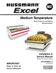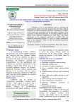
1
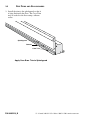
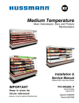
Rear Roll-in Dairy Medium Temperature Free Standing or Suspended Merchandisers Installed in Walk-in Cooler Exterior Walls Installation & Service Manual Shipped With Case Data Sheets IM P OR T A N T Keep in store for future reference! MANUAL- I/O EXCEL REAR ROLL-IN DAIRY P/N 0485219_B Excel Series July 2014 Spanish 0532258 French 0532259 P/N 0485219_B TABLE OF CONTENTS INSTALLATION NSF Certification . . . . . . . . . . . . . . . . . . . Model Description . . . . . . . . . . . . . . . . . . Location. . . . . . . . . . . . . . . . . . . . . . . . . . . Shipping Damage. . . . . . . . . . . . . . . . . . . . Exterior Loading . . . . . . . . . . . . . . . . . . . . Merchandiser Ends . . . . . . . . . . . . . . . . . . Shipping Braces . . . . . . . . . . . . . . . . . . . . . Leveling. . . . . . . . . . . . . . . . . . . . . . . . . . . . Installing D5XRRIS . . . . . . . . . . . . . . . . . Installing D5XRRI . . . . . . . . . . . . . . . . . . Rear Curtain Installation . . . . . . . . . . . . . Joining Instructions. . . . . . . . . . . . . . . . . . Installing Partitions . . . . . . . . . . . . . . . . . . REFRIGERATION / ELECTRICAL Refrigerant. . . . . . . . . . . . . . . . . . . . . . . . . Refrigerant Piping . . . . . . . . . . . . . . . . . . . Insulation. . . . . . . . . . . . . . . . . . . . . . . . . . Suction Line. . . . . . . . . . . . . . . . . . . . . . . . Liquid Line. . . . . . . . . . . . . . . . . . . . . . . . . Refrigeration Thermostat . . . . . . . . . . . . . Defrost Termination . . . . . . . . . . . . . . . . . Defrost Sequences . . . . . . . . . . . . . . . . . . . Merchandiser Electrical Data . . . . . . . . . . Electrical Connections. . . . . . . . . . . . . . . . Field Wiring. . . . . . . . . . . . . . . . . . . . . . . . Identification of Wiring. . . . . . . . . . . . . . . Wiring Color Code . . . . . . . . . . . . . . . . . . 1-1 1-1 1-1 1-1 1-2 1-2 1-2 1-2 1-3 1-5 1-5 1-5 1-5 2-1 2-1 2-2 2-2 2-2 2-3 2-3 2-3 2-4 2-4 2-4 2-4 2-4 DRIP PIPING AND SPLASHGUARDS Waste Outlet . . . . . . . . . . . . . . . . . . . . . . . 3-1 Installing Drip Piping. . . . . . . . . . . . . . . . . 3-1 Sealing Splashguard to Floor . . . . . . . . . . 3-1 START UP / OPERATION Start up. . . . . . . . . . . . . . . . . . . . . . . . . . . . Stocking . . . . . . . . . . . . . . . . . . . . . . . . . . . Optional Shelving . . . . . . . . . . . . . . . . . . . Accessories . . . . . . . . . . . . . . . . . . . . . . . . . Load Limits . . . . . . . . . . . . . . . . . . . . . . . . Installing FDA/NSF Thermometer . . . . . . . . 4-1 4-1 4-1 4-2 4-2 4-2 MAINTENANCE Care and Cleaning. . . . . . . . . . . . . . . . . . . Cleaning Honeycomb Assemblies. . . . . . . Removing Return Air Grille . . . . . . . . . . . Removing Scratches from Bumper. . . . . . 5-1 5-2 5-3 5-4 SERVICE Replacing Fan Motors and Blades . . . . . . Replacing Fluorescent Lamps. . . . . . . . . . Replacing Lamp Holders and End Caps. . Replacing Ballasts . . . . . . . . . . . . . . . . . . . Repairing Aluminum Coils . . . . . . . . . . . . 6-1 6-2 6-2 6-3 6-4 WARRANTY IMPORTANT KEEP IN STORE FOR FUTURE REFERENCE Quality that sets industry standards! 12999 St. Charles Rock Road • Bridgeton, MO 63044-2483 U.S. & Canada 1-800-922-1919 • Mexico 1-800-522-1900 www.hussmann.com © 2014 Hussmann Corporation iv REVISION HISTORY REVISION B 1.Added Proposition 65 Warning Statement REVISION A 1.Revised to Excel, page 1-2, 1-3, 1-4, 2-1, 2-3, 3-1, 3-2, 4-2, 5-2. REVISION HISTORY — Original Issue ************************** ANSI Z535.5 DEFINITIONS • DANGER – Indicate[s] a hazardous situation which, if not avoided, will result in death or serious injury. • WARNING – Indicate[s] a hazardous situation which, if not avoided, could result in death or serious injury. • CAUTION – Indicate[s] a hazardous situation which, if not avoided, could result in minor or moderate injury. • NOTICE – Not related to personal injury – Indicates[s] situations, which if not avoided, could result in damage to equipment. P/N 0485219_B U.S. & Canada 1-800-922-1919 • Mexico 1-800-522-1900 • www.hussmann.com P/N 0485219_B 1-1 INSTALLATION NSF CERTIFICATION LOCATION These merchandisers are manufactured to meet ANSI / National Sanitation Foundation (NSF®) Standard #7 requirements. Proper installation is required to maintain certification. Near the serial plate, each case carries a label identifying the type of application for which the merchandiser was certified. These merchandisers are designed for displaying products in air conditioned stores where temperature is maintained at or below the ANSI/NSF-7 specified level and relative humidity is maintained at or below 55%. ANSI/NSF-7 Type I – Display Refrigerator / Freezer Intended for 75°F / 55%RH Ambient Application ANSI/NSF-7 Type II – Display Refrigerator / Freezer Intended for 80°F / 55%RH Ambient Application ANSI/NSF-7 – Display Refrigerator Intended for Bulk Produce MODEL DESCRIPTION The D5XRRI and D5XRRIS models are designed for installation against an opening in the cooler wall. The merchandisers are open at the rear. Once installed, product can be rolled directly from the cooler through the rear of the merchandiser into the refrigerated display area. The D5XRRI is a self-supporting model with the canopy and front sections connected by welded end supports. The D5XRRIS is manufactured in two sections: a Coil Package and a Front Package. The coil package is to be suspended against the cooler wall, above the opening, from an adequate supporting structure in the store. The front ! package completes the D5XRRIS model once it has been aligned with the coil package and anchored to the floor. CAUTION ! WARNING Do not store items or flammable materials on top of the case. HUSSMANN CORPORATION • BRIDGETON, MO 63044-2483 U.S.A. Like other merchandisers, these are sensitive to air disturbances. Air currents passing around cases will seriously impair their operation. Do NOT allow air conditioning, electric fans, open doors or windows, etc. to create air currents around the merchandisers. Product should always be maintained at proper temperature. This means that from the time the product is received, through storage, preparation and display, the temperature of the product must be controlled to maximize the life of the product. For California Businesses: This product may contain chemicals known to the State of California to cause cancer, birth defects, or other reproductive harm. This warning is the result of the California State law known as the California Safe Drinking Water and Toxic Enforcement Act of 1986, which is commonly referred to as “Proposition 65.” This warning does not mean that Hussmann products will cause cancer or reproductive harm, or is in violation of any product-safety standards or requirements. As clarified by the California State government, Proposition 65 can be considered more of a ‘right to know’ law than a pure product safety law. When used as designed, Hussmann believes that our products are not harmful. We provide the Proposition 65 warning to stay in compliance with California State law. It is your responsibility to provide accurate Proposition 65 warning labels to your customers when necessary. For more information on Proposition 65, please visit the California State government website. Medium Temperature Excel Installation 1-2 SHIPPING DAMAGE EXTERIOR LOADING All equipment should be thoroughly examined for shipping damage before and during unloading. Do NOT walk on top of merchandisers or damage to the merchandisers and serious personal injury could occur. They are not This equipment has been carefully inspected at our factory. Any claim for loss or damage must be made to the carrier. The carrier will provide any necessary inspection reports and/or claim forms. structurally designed to support excessive external loading such as the weight of a Apparent Loss Or Damage If there is an obvious loss or damage, it must be noted on the freight bill or express receipt and signed by the carrier’s agent; otherwise, carrier may refuse claim. MERCHANDISER ENDS Concealed Loss Or Damage When loss or damage is not apparent until after equipment is uncrated, retain all packing materials and submit a written request to the carrier for inspection, within 15 days. ! CAUTION ! WARNING Do NOT remove shipping braces until the merchandisers are positioned for installation. Once unfastened, NEVER LEAVE THE MERCHANDISER UNSUPPORTED OR UNATTENDED until it has been anchored. P/N 0485219_B person. Do not place heavy objects on the case. Ends for the D5XRRI and D5XRRIS rear load dairy models are shipped separately to be field installed after the merchandisers are installed in the cooler wall. Refer to separate instructions shipped with the ends. SHIPPING BRACES Move the merchandiser as close as possible to its permanent location and then remove all packaging. Check for damage before discarding packaging. Remove all separately packed accessories such as kits and shelves. The D5XRRI is top-heavy and must be supported and moved with care at all times until it has been securely anchored. It must be supported while it is being unfastened from the skid and when it is removed from the skid. Once the skid has been unfastened, never leave the merchandiser unsupported or unattended until it has been anchored. U.S. & Canada 1-800-922-1919 • Mexico 1-800-522-1900 • WWW.HUSSMANN.COM P/N 0485219_B 1-3 LEVELING Merchandisers must be installed level to ensure proper operation of the refrigeration system and to ensure proper drainage of defrost water. When leveling merchandisers, use a carpenter’s level as shown. Leveling shims are provided with each merchandiser for use if needed. The shims are long enough to allow leveling of adjoining merchandisers at the same time using only one shim. ! CAUTION Do not walk or put heavy objects on case. ! WARNING NOTES: • Begin lineup leveling from the highest point of the store floor. • If shimming two corners, check to see if a shim is needed in the center of the case. If a gap exists between the support rail of the case and the floor, a shim should be placed in the center. Levels Shim HUSSMANN CORPORATION • BRIDGETON, MO 63044-2483 U.S.A. Medium Temperature Excel Installation 1-4 INSTALLING D5XRRIS Cantilevered “I” Beam Overview The coil package must be suspended above the cooler wall opening from an adequate support structure. It is imperative that both the method and the materials used to suspend the coil package be of sufficient strength to support the coil package. Hanging Support Spacing Case Length ft (mm) Coil Package Weight lb (kg) Minimum Number of 1/2 in. dia. (12.7 mm) Threaded Drop Rods Required Store Joist 8 (2438)485 (220)4 12 (3658)750 (340)6 These models are designed for use with roll-in carts or free-standing (unattached) shelving. DISCLAIMER: These methods of securing the coil package are suggestions only. It is the responsibility of the store designer, installer and end user to ensure the store’s structural capacity. Hussmann assumes no liability for consequences resulting from failure of store structure or material used in installation. Two 15/8 x 15/8 inch (41 x 41 mm) channel struts are provided for hanging the coil package. These struts extend the full length of the case and are bolted to the case at the factory. Use 1/2 in. (12.7 mm) clamp nuts to secure the hanging rods to the struts. Although these struts allow flexibility in hanging rod location, the end support rods must be within 12 in. (305 mm) of the coil package end. For a 12 ft (3658 mm) coil package, the center hanging rods must be within 12 in. (305 mm) of the center of the merchandiser. Field Supplied Suspending Rods Channel Struts Coil Package P/N 0485219_B U.S. & Canada 1-800-922-1919 • Mexico 1-800-522-1900 • WWW.HUSSMANN.COM P/N 0485219_B 1-5 Installing Coil Package Installing Front Package Attach the coil package to the selected store structural support using the suggested drop rod size, quantity and fastening method, or as locally engineered. The coil package must be leveled. Align the front section with the canopy. Shim as necessary to maintain level. Fasten anchor brackets to floor. Seal as indicated. INSTALLING D5XRRI Apply silicone sealant between the “L” bracket and bottom of cooler wall as shown. Fasten the “L” bracket at the top rear of the coil package to the cooler wall to prevent sway or lateral movement. The “L” bracket has holes for this purpose. Once lineup is complete, apply silicone or butyl sealant on outside where “L” bracket and wall meet, and on inside where wall and bracket meet to prevent condensation in walls. Sealing is also required to facilitate cleaning to NSF guidelines. The channel struts with clamping nuts are provided to fasten the suspending rods. When tightening 1/2 in. (12.7 mm) threaded rods into nuts, ensure that the rods are firmly screwed into place. Vibration pads must be used if a machine room or or other machinery is located above the structure that supports the coil package. Nut Lock Washer 22 in. (559 mm) Drop Rods Level 8 in. (203 mm) Cooler Compartment Wall Seal Coil Package 80 in. (2032 mm) Seal Rear Suspension Channel Return Grille Cooler Compartment Front Package Seal Suspending Rod Flat Washer Anchor Seal Vibration Pad (if required) Flat Washer or Plate (used with Vibration Pad) Floor Line 3/4 in. 32 (832 mm) Store Structure Flat Washer Nut Suspending Rod Clamping Nut Case Channel Strut Case HUSSMANN CORPORATION • BRIDGETON, MO 63044-2483 U.S.A. Medium Temperature Excel ! CAUTION Installation 1-6 ! WARNING Do NOT remove shipping braces until the merchandisers are positioned for installation. Once unfastened, NEVER LEAVE THE MERCHANDISER UNSUPPORTED OR UNATTENDED until it has been anchored. Stop The D5XRRI must be securely anchored to the floor and cooler wall after it has been leveled in its permanent position. Prelocated anchoring holes are provided in the front assembly, uprights, side braces, and top “L” bracket. Curtain Hanger Sealing JOINING For proper performance, safety and sanitation, apply a generous bead of sealant between the D5XRRI and the floor, between the D5XRRI top and sides and the cooler wall, around the interior perimeter of the base at the floor, and along the exterior front of the base at the floor. Sectional construction means that two or more merchandisers may be joined in line yielding one long continuous display requiring only one pair of ends. Joint kits and instructions are shipped with each merchandiser. REAR CURTAIN INSTALLATION Rear curtains are provided with each case, two per 8 ft model, 3 per 12 ft model. Curtains should be installed just before start-up to prevent damage. 1. Slide all hangers onto track at rear of the case. Use ALL hangers so the curtains will drape properly. 2. Snap a stop clip onto each end of the track. 3. Hang curtains on hangers. P/N 0485219_B To join like merchandisers, a joint assembly is required. A 11/2 inch (38 mm) partition kit is required to join unlike merchandisers, or like merchandisers operating at different temperatures. All joints must be air-tight to prevent formation of ice or condensation. Refer to separate joining instruction shipped with each merchandiser. INSTALLING PARTITIONS To join unlike fixtures, or like merchandisers operating at different temperatures, a 11/2 in. (38 mm) partition kit is required. Instructions for installing these partitions are included with the kits. U.S. & Canada 1-800-922-1919 • Mexico 1-800-522-1900 • WWW.HUSSMANN.COM P/N 0485219_B 2-1 REFRIGERATION / ELECTRICAL REFRIGERANT The correct type of refrigerant will be stamped on each merchandiser’s serial plate. The case refrigeration piping is leak tested, factory sealed and pressurized. Before making refrigeration hookups, depress the ! universal line valve to ensure that coils have maintained pressure during shipment. CAUTION ! WARNING Refrigeration lines are under pressure and should be depressurized before attempting to make any connections. REFRIGERANT PIPING ! CAUTION When brazing pipes, be sure to use the insulation blanket shipped with the case to prevent damage to the case. ! WARNING Piping Area Coil Fan C O O L E R W A L L Connection Location The refrigerant line connections are at the lefthand end of the merchandiser (as viewed from the front). After connections have been made, seal this outlet thoroughly. Seal both the inside and the outside. We recommend using an expanding polyurethane foam insulation. Multiplexing Multiplex piping must be run above the top of the coil package in the area shown. Observe proper suction pipe joining practices and insulate all suction piping outside the merchandiser to prevent drippage from condensate. Line Sizing Refrigerant lines should be sized as shown on the refrigeration legend that is furnished for the store or according to ASHRAE guidelines. Refer to the information on the next page for branch line piping of Hussmann Equipment. Oil Traps P-traps (oil traps) must be installed at the base of all suction line vertical risers. Pressure Drop Pressure drop can rob the system of capacity. To keep the pressure drop to a minimum, keep the refrigerant line run as short as possible using a minimum number of elbows. Where elbows are required, use long radius elbows only. HUSSMANN CORPORATION • BRIDGETON, MO 63044-2483 U.S.A. Medium Temperature Excel 2-2 Refrigeration / Electrical INSULATION LIQUID LINE The suction and liquid lines should be clamped or taped together and insulated for a minimum of 30 ft (9144 mm) from the merchandiser. • May be reduced by one size after one half the case run load. Do not reduce below the case liquid line connection size. Additional insulation for the balance of the liquid and suction lines is recommended wherever condensation drippage is objectionable or lines are exposed to ambient conditions. • Take-offs to merchandiser liquid lines should exit the bottom of the branch liquid line. Provide an expansion loop for each evaporator take-off (minimum 3 in. [76 mm] loop). SUCTION LINE • Pitch in direction of flow. • May be reduced by one size at one third of case run load and again after the second third. Do not reduce below the case suction line size. Minimum Loop 3-in. (76 mm) Liquid Line Take Off • Merchandiser suction lines should enter at the top of the branch line. Suction Line Return Offtime Defrost 8 Ft Case (2438 mm) 12 Ft Case (3658 mm) 8 Ft Case (2438 mm) 12 Ft Case (3658 mm) Liquid Line Suction Line P/N 0485219_B U.S. & Canada 1-800-922-1919 • Mexico 1-800-522-1900 • www.hussmann.com N G R P/N 0485219_B 2-3 REFRIGERATION THERMOSTAT DEFROST TERMINATION The bulb for the optional refrigeration thermostat is located approximately 2 in. (51 mm) in front of the coil and 6 ft (1829 mm) from the righthand end (facing front) of the case. The optional refrigeration thermostat is located 4 1/2 ft (1372 mm) from the right-hand end. Rear load dairy cases are designed for time terminated defrost only. Refer to the merchandiser data sheet shipped with this manual for correct settings. ! CAUTION ! WARNING — LOCK OUT / TAG OUT — To avoid serious injury or death from electrical shock, always disconnect the electrical power at the main disconnect when servicing or replacing any electrical component. This includes, but is not limited to, such items as doors, lights, fans, heaters, and thermostats. ! DANGER DEFROST SEQUENCES These merchandisers require defrost cycles for proper operation. Refer to the data sheets for application data. The Time Clock initiates defrost. The evaporator fans continue to circulate air across the evaporator coil, melting any frost build-up. Defrost must be time terminated. CAUTION NOTICE Optional Refrigeration Thermostat Optional Refrigeration Thermostat Bulb HUSSMANN CORPORATION • BRIDGETON, MO 63044-2483 U.S.A. Medium Temperature Excel Refrigeration / Electrical 2-4 MERCHANDISER ELECTRICAL DATA FIELD WIRING Merchandiser data sheets are included with this manual. The data sheets provide merchandiser electrical data, electrical schematics, parts lists and performance data. Refer to the merchandiser data sheets and merchandiser serial plate for electrical information. Field wiring must be sized for component amperes stamped on the serial plate. Actual ampere draw may be less than specified. Field wiring from the refrigeration control panel to the merchandisers is required for defrost termination thermostats and for optional refrigeration thermostats. When multiple merchandisers are on the same defrost circuit, the defrost termination thermostats are wired in series. always check the serial plate for component amperes. ELECTRICAL CONNECTIONS All wiring must be in compliance with NEC and local codes. All electrical connections are to be made in the electrical raceway or Handy Box. ! Leads for all electrical circuits are identified by colored plastic bands. These bands correspond to the color code sticker (shown below) located inside the merchandiser’s raceway. CAUTION Optional T8 rail lights and optional Quick Connect spray hose or field-installed misting system ! not be used together. shall WARNING IDENTIFICATION OF WIRING ALWAYS CHECK THE SERIAL PLATE FOR COMPONENT AMPERES WIRING COLOR CODE Leads for all electrical circuits are identified by a colored plastic band: neutral wire for each circuit has either White insulation or a White plastic sleeve in addition to the color band. Pink............ Refrig. Thermostat Low Temp. Orange or Light Blue. Refrig. Thermostat Norm Temp. Tan..........Lights Dark Blue.. Defrost Term. Thermostat Maroon...Receptacles Purple........ Condensate Heaters Yellow....Defrost Heaters 120V Brown........ Fan Motors Red . .......Defrost Heaters 208V *Either colored Sleeve Or Colored Insulation Green*........ Ground ELECTRICIAN NOTE: Use copper conductor wire only. CASE MUST BE GROUNDED These P/N 0485219_B are marker colors wires may vary. U.S. & Canada 1-800-922-1919 • Mexico 1-800-522-1900 • www.hussmann.com P/N 0485219_B 3-1 DRIP PIPING AND SPLASHGUARDS WASTE OUTLET A waste outlet is located at the back of the upper fan plenum, 1 1/4 in. (32 mm) from either end of the merchandiser. 4. Avoid long runs of drip piping. Long runs make it impossible to provide the pitch necessary for good drainage. It is the responsibility of the installing contractor to supply and connect drip pipe external to the case. External drip pipe may be flexible or rigid. 5. Provide a suitable air break between flood rim of the floor drain and outlet of drip pipe. To meet code on low base cases, it may be necessary to install a field-supplied drip pipe reducer. An alternative is to cut the last section of drip pipe at an angle. 6. Prevent drip pipes from freezing: A. Do NOT install drip pipes in contact with uninsulated suction lines. Suction lines should be insulated with a nonabsorbent insulation material. B. Where drip pipes are located in dead air spaces, such as between cases or between a case and a store wall, provide means to prevent freezing. Waste Outlet at End (connect drip pipe here) 5XR R IS INSTALLING DRIP PIPING Poorly or improperly installed drip pipes can seriously interfere with the merchandiser’s operation and result in costly maintenance and product losses. Please follow the recommendations listed below when installing drip pipes to ensure proper installation. 19 7/8 (504) 17 1/2 (444) 1. Never use drip piping smaller than the nominal diameter of the piping inside the merchandiser. 2. When connecting drip piping, the “water seal” must be used as part of the drip piping to prevent air leakage or insect entrance. Never use two water seals in series in any one drip pipe. D ouble water seals in series will cause an air lock and prevent draining . SEALING SPLASHGUARD TO FLOOR Stainless steel splashguards may be sealed to the floor using a vinyl cove base trim. The size of trim needed will depend on how much the floor is out of level. To install the trim to the splashguard: 1. Remove all dirt, wax and grease from the area of the splashguard where adhesion will be necessary. This is to ensure a good and secure installation. 2. Apply a good contact cement to the cove trim and allow proper drying time according to the directions supplied with the cement. 3. Pitch the drip piping in the direction of flow. There should be a minimum pitch of 1/4 in. per ft (20 mm per 1m). HUSSMANN CORPORATION • BRIDGETON, MO 63044-2483 U.S.A. Medium Temperature Excel 3-2 Drip Piping and Splashguards 3. Install the trim to the splashguard so that it is lying flush with the floor. The Cove Trim may be sealed to the floor using a silicone sealer. Splashguard Cement Cove Trim Apply Cove Base Trim to Splashguard P/N 0485219_B U.S. & Canada 1-800-922-1919 • Mexico 1-800-522-1900 • www.hussmann.com P/N 0485219_B 4-1 START UP / OPERATION START UP See the specific model’s Technical Data Sheet for refrigerant settings and defrost requirements. Bring merchandisers down to the operating temperatures listed on the data sheet. Each four foot section has its own evaporator coil and pre-set non-adjustable thermostatic expansion valve (TEV). No adjustment is required. Do not remove the cap on the TEVs. This cap is to be removed only for valve disassembly. Removal of this cap during case maintenance will result in refrigerant loss unless the system is first isolated and the refrigerant recovered. ! CAUTION removal of the tev cap will result in refrigerant loss unless the system is first isolated and the refrigerant recovered. ! WARNING The TEV has been factory set to provide the recommended performance settings as specified on the merchandiser data sheets. STOCKING Product should NOT be placed in merchandisers until merchandiser is at proper operating temperature. Close-off curtains at the rear of the D5XRRI and D5XRRIS must be kept closed except when stocking to avoid adverse refrigeration performance. OPTIONAL SHELVING Product display shelving, lighted or unlighted, may be added to these cases with the addition of shelf support kits. These modular kits may be installed in the entire length or any 4 ft (1219 mm) section. Shelf Supports Two optional shelf support types are available. The stub shelf supports attach to the top coil package for one or two rows of shelves. The other shelf supports are 60 in. (1524 mm) tall, bolted to the floor, and support up to four rows of shelves. An 8 ft (2438 mm) merchandiser has two columns of shelves; a 12 ft (3658 mm) merchandiser has three columns of shelves. Shelves Optional shelving is available in 20 in. (508 mm), 22 in.(559 mm), and 24 in. (610 mm) size. If using more than one size shelf in a column, the smallest shelf must be the highest Proper rotation of product during stocking is necessary to prevent product loss. Always bring the oldest product to the front and set the newest to the back. Air discharge and return flues must remain open and free of obstruction at all times to provide proper refrigeration and air curtain performance. Do not allow product, packages, signs, etc. to block these grilles. HUSSMANN CORPORATION • BRIDGETON, MO 63044-2483 U.S.A. Medium Temperature Excel 4-2 Start up / Operation Do not block honeycomb. ACCESSORIES Various display arrangements can be achieved by through combinations of shelves and mobile dairy carts. These carts are designed for quick loading, maneuverability, and sales appeal. After loading, the carts glide into the case from the rear. They can be positioned under optional shelving. INSTALLING FDA/NSF REQUIRED D5XRRIS Do not use non-approved shelving, baskets, display racks, or any accessory that could hamper air curtain performance. Consult your Hussmann representative when in doubt about the effects of third-party accessories. Cold Air Curtain LOAD LIMITS Shelf life of perishables will be short if load limit is violated. At no time should cases be stocked beyond the load limits indicated. Load Limit THERMOMETER The following pages provide the same information that ships with the thermometer. This requirement does not apply to display refrigerators intended for bulk produce (refer to page 1-1). Please note that the tape cannot be exposed after installation. P/N 0485219_B U.S. & Canada 1-800-922-1919 • Mexico 1-800-522-1900 • WWW.HUSSMANN.COM P/N 0485219_B 4-3 This is an NSF-7 & US FDA Food Code Required Thermometer Suggested Mounting Locations in Single Deck Glass Front Impact Merchandisers – Acrylic Package Guard, Facing Out Thermometer – Hussmann Part TM.4911251 Hussmann Corporation • 12999 St. Charles Rock Road • Bridgeton, MO 63044-2483 U.S. & Canada 1-800-922-1919 • Mexico 1-800-522-1900 • www.hussmann.com © 2007 Hussmann Corporation Double Stick Tape – Inside End Panel – Shelf Price Tag Molding – Return Air Grille Flexible Plastic Fits in Price Tag Moldings Hussmann P/N 0429971_C Suggested Mounting Locations in Multi-deck Merchandisers 10/2007 HUSSMANN CORPORATION • BRIDGETON, MO 63044-2483 U.S.A. Medium Temperature Excel 4-4 Start up / Operation Important – Please read! This thermometer is provided in response to United States Food and Drug Administration (US FDA) Food Code [ http://www.fda.gov/ ] and National Sanitation Foundation (NSF / ANSI) Standard 7 [ http://www.nsf.org/ ] Each installation will be different The thermometer may need to be depending on how the unit is moved several times to find the stocked, shopping patterns in the warmest location. Mounting options department and ambient conditions include flexible plsatic for price tag of the store. The suggested locations molding application, magnet provided herein are possible applied to back of flexible plastic for locations. It is the responsibility of steel end wall, and double stick the purchaser / user to determine tape. Tape must not be exposed the location with the food storage after installation. area of the unit that best meets the code requirements above. Questions about either code should be addressed to local agencies or other appropriate officals. Keep with merchandiser or give to store manager. DO NOT DESTROY. P/N 0485219_B U.S. & Canada 1-800-922-1919 • Mexico 1-800-522-1900 • WWW.HUSSMANN.COM N G R N G R P/N 0485219_B 5-1 MAINTENANCE CARE AND CLEANING Long life and satisfactory performance of any equipment is dependent upon the care it receives. To ensure long life, proper sanitation and minimum maintenance costs, these cases should be thoroughly cleaned, all debris removed and the interiors washed down, weekly. The store floor will be the interior display area of the rear roll-in dairy cases. Since milk and other spillage will occur, the floor should be cleaned and sanitized at least once each week. When cleaning, use caution to prevent water or other liquids from entering the fan vents on the interior side of the front assembly. Exterior Surfaces The exterior surfaces must be cleaned with a mild detergent and warm water to protect and maintain their attractive finish. N ever use abrasive cleansers or scouring pads . ! CAUTION ! WARNING Prevent injury. Always shut power off during cleaning process. ! DANGER Interior Surfaces The interior surfaces may be cleaned with most domestic detergents, ammonia based cleaners and sanitizing solutions with no harm to the surface. CAUTION ! CAUTION WARNING ! NOTICE Product will be degraded and may spoil if allowed to sit in a non-refrigerated area. ! DANGER HUSSMANN CORPORATION • BRIDGETON, MO 63044-2483 U.S.A. CAUTION Do NOT Use: • Abrasive cleansers and scouring pads, as these will mar the finish. • A hose on lighted shelves or submerge the shelves in water. • Solvent, oil or acidic based cleaners on any interior surfaces. • Coarse paper towels on coated glass. • Ammonia-based cleaners on acrylic parts. • A hose on rail lights, canopy lights or any other electrical connection. • steam or high water pressure hoses to wash the interior . These will destroy the cases’ sealing causing leaks and poor performance. Do: • Remove the product and all loose debris to avoid clogging the waste outlet. • Store product in a refrigerated area such as a cooler. Remove only as much product as can be taken to the cooler in a timely manner. • First turn off refrigeration, then disconnect electrical power. • Sweep the floor of the case. • Thoroughly clean all surfaces with soap and hot water. D o not use steam or high water pressure hoses to wash the interior . These will destroy the cases’ sealing causing leaks and poor performance. • Take care to minimize direct contact between fan motors and cleaning or rinse water. • Rinse with hot water, but do NOT flood. Never introduce water faster than the waste outlet can remove it. • Allow cases to dry before resuming operation. • Wipe down lighted shelves with a damp sponge or cloth so that water does not enter the light channel. Do not use a hose or submerge shelves in water. Wipe dry. • After cleaning is completed, turn on power to the merchandiser. Medium Temperature Excel 5-2 Maintenance CLEANING HONEYCOMB ASSEMBLIES Upper Honeycomb Honeycombs should be cleaned at least every six months. Dirty honeycombs will cause cases to perform poorly. The honeycombs may be cleaned with a vacuum cleaner. Soap and water may be used if all water is removed from the honeycomb cells before replacing. Be careful not to damage the honeycombs. 1. Remove interior roof panel to free honeycomb. Lower Honeycomb Starting at one lower end of the honeycomb, use a needle-nose plier to carefully compress and lift a corner. Work along the edge a few cells at a time until the honeycomb is free of the retainer. Clean and dry the honeycomb, then replace in reverse order. Note that a damaged honeycomb must be replaced to maintain refrigeration efficiency. 2. Clean and dry the honeycomb. 3. After cleaning, replace honeycomb and interior roof panel. ! CAUTION ! CAUTION ! WARNING ! WARNING Honeycomb ! DANGER CAUTION NOTICE P/N 0485219_B — LOCK OUT / TAG OUT — To avoid serious injury or death from electrical shock, always disconnect the electrical power at the main disconnect when servicing or replacing any electrical component. This includes, but is not limited to, such items as doors, lights, fans, heaters, and thermostats. ! DANGER CAUTION NOTICE U.S. & Canada 1-800-922-1919 • Mexico 1-800-522-1900 • WWW.HUSSMANN.COM P/N 0485219_B 5-3 REMOVING RETURN AIR GRILLE Remove the screws holding each end of the retainer. Remove the retainer, then lift out the return air grille Lower Fan Plenum Remove the return air grille, then remove the screws that hold the plenum and lift out the plenum. Remove Screws Return Air Grille Lifts Out Remove Screws Remove Screw Honeycomb Remove Screw Cart Stop Interior View of D5XRRIS Front Package HUSSMANN CORPORATION • BRIDGETON, MO 63044-2483 U.S.A. Medium Temperature Excel 5-4 Maintenance Canopy Fan Plenum To facilitate cleaning, the fan plenum is hinged. After cleaning be sure the plenum is returned to the proper position or product loss will result due to improper refrigeration. REMOVING SCRATCHES FROM BUMPER Most scratches and dings can be removed using the following procedure. 1. Use steel wool to smooth out the surface area of the bumper or top rail. 2. Clean area. 3. Apply vinyl or car wax and polish surface for a smooth glossy finish. P/N 0485219_B U.S. & Canada 1-800-922-1919 • Mexico 1-800-522-1900 • WWW.HUSSMANN.COM P/N 0485219_B 6-1 SERVICE REPLACING FAN MOTORS AND BLADES See cross section for location of evaporator and return air fans. Should it ever be necessary to service or replace the fan motors or blades be certain that the fan blades are re-installed correctly. For access to evaporator fans: For access to return air fans: 1. Turn off power. 2. Remove dairy carts, or bottom shelving. 3. Remove return air grille. 4. Disconnect fan from wiring harness. 1. Turn off power. 5. Remove fan plenum from front package. 2. Remove upper shelving. 6. Remove fan blade. 3. Disconnect fan from wiring harness. 7. Remove screws holding bottom of motor to fan basket. 4. Remove fan mounting panel from coil module. 5. Remove wire fan guard. 8. Replace fan motor and blade. 9. Reconnect fan to wiring harness. 6. Remove fan blade. 10. Re-install fan plenum and return grille 7. Remove screws holding bottom of motor to fan basket. 11. Turn on power. Verify that motor is working and blade is turning in the correct direction. 8. Replace fan motor and blade. 9. Re-install fan mounting panel in coil module. 10. Reconnect fan to wiring harness. 11. Turn on power. Verify that motor is working and blade is turning in the correct direction. 12. Ensure the fan plenum is located properly and that there are no air leaks which would ! adversely affect case performance. CAUTION 13. Bring merchandiser to operating temperature before restocking. ! WARNING — LOCK OUT / TAG OUT — To avoid serious injury or death from electrical shock, always disconnect the electrical power at the main disconnect when servicing or replacing any electrical component. This includes, but is not limited to, such items as doors, lights, fans, heaters, and thermostats. HUSSMANN CORPORATION • BRIDGETON, MO 63044-2483 U.S.A. 12. Ensure the fan plenum is located properly and that there are no air leaks which would adversely affect case performance. 13. Bring merchandiser to operating temperature before restocking. Fan Plenum in Front Package (Lifts Out) Case Interior Wiring Harness Fan Blade Electrical Connection Box Medium Temperature Excel Service 6-2 REPLACING LED CANOPY LIGHT BARS There are always two rows of canopy LED lights. The rear light bar illuminates the upper section of the case and the front light bar illuminates the lower section of the case. The front and rear light bars are labeled front and rear respectively and have a different shaped lens. They shall not be interchanged. The light bars are connected through a twoconductor connector. Push on the release tab on the connector, then pull down on the connector. Do not pull on wires. LED power source is 24-volts for safety. Front Canopy LED Light Bar FRONT P/N XXXXXX AM P/N XXXXXX DATE CODE: XXXXX COLOR TEMP: XXXXX INPUT VOLTAGE: 24VDC (+RED, -BLU) Rear Canopy LED Light Bar P/N XXXXXX AM P/N XXXXXX DATE CODE: XXXXX COLOR TEMP: XXXXX INPUT VOLTAGE: 24VDC (+RED, -BLU) REAR Front Rear Canopy LED Light Bar Canopy LED Light Bar REPLACING LED Canopy LED Light Connector The light bars are attached to the lamp panel using clips. When replacing clips ensure that the part number of the clip is the same as the original clip. The clips are color coded to simplify identification of the proper clip to be used. SHELF LIGHT BARS The LED shelf light bars are held in place using a magnetic surface on the back of the light bar. P/N 0501208 WHITE GRAY BEIGE Label Detail P/N 0501208 LED Shelf Light Bar Light Bar Clips P/N 0485219_B U.S. & Canada 1-800-922-1919 • Mexico 1-800-522-1900 • www.hussmann.com P/N 0485219_B 6-3 1. Disconnect power to the merchandiser. 1. Turn off power to the merchandiser, and turn canopy light switch off. Unplug the shelf connector from its socket. 2. Remove light bars from the canopy. 2. Replace with the appropriate Hussmann LED light bar. 3. Remove the screws that secure the lamp panel. ShelfC onnectorH andle 4. Grasp the lamp panel at its front edge and C rossbar carefully pull down. It will swing freely from its hinged rear edge. Latch Tongue 5. Replace power supply and reassemble parts in reverse order. 6. Reconnect the electrical power. ShelfShelf LightLight R eceptacle ShelfLight LightPl ug Shelf Plug Receptacle REPLACING LED POWER SUPPLIES The LED power supplies for canopy lights and shelf lights are located at the top of the merchandiser inside the canopy. Power Supply A 1.200 8 A C E I S N I 1.185 1.110 1.005 .945 N: E T-35 ESC I TION A I C. N ATE A EN 05 07 90 .C 7 8 7 C E S N I S N I E N: E T-35-1 ESC I TION N I C. ATE EN 05 07 09 6 A 7 1.78 .126 ATE EN 05 07 09 A .C 5 6 5 RH Shelves Canopy .120 .587 .059 .37 6 4 4 5 5 .245 B 4 .38 4 4 .464 12 ft .0 12 A .458 2 3 0.25 . O I INAL ATE IAL: . . ESI N : 0.10 0.05 05 07 09 NLESS OT E ISE S ECI IE TOLE ANCE IN INC 2 S N I A C E .C .C I N O ATION C. EN I ATE IAL: 1 12 . . ESI N : 0.10 0.05 05 07 09 S N I S S N I A IN T-35 L A C E A 980507 LH Shelves A C E .C .C I N O ATION C. EN I Center Shelves 22 43 3 0.25 . O I INAL ATE IAL: 1 . . ESI N : 0.10 0.05 05 07 09 S N I S A C S N I 0 A IN T-35 L NO A C E O ATION 1 T-36-1 .C .C I N E CO E A T NA E: INIS : 0 SCALE S EET NONE NLESS OT E ISE S ECI IE TOLE ANCE IN INC 1 E T-35 0 0 NO E CO 2 .293 A T NA E: INIS : SCALE S EET NONE 3 0.25 . O I INAL E T-35-1 INIS : 0 C E CO A T NA E: 2 2 2 SECTION A-A SCALL 1:1 A S N I S .0 1.38 .492 2 1 NLESS OT E ISE S ECI IE TOLE ANCE IN INC 1 3 .08 .06 .285 .295 3 .197 .445 3 .775 3 .147 .071 .465 3 3 4 3 T .56 .202 5 .74 .039 0 ELEASE .12 C .07 TOOLIN .55 O A 4 .440 .56 5 A N C. 6 5 7 LH Shelves 6 6 T-36-1 ESC I TION 7 A A .760 8 A 7 .458 6 N: 8 .154 .C .047 A 8 E I A .485 .098 L .120 I .312 E 1.162 C L E 7 8 A I .120 1.380 A 2.60 8 .065 6 ft & 8 ft L E C. EN SCALE S EET NONE I 12 A IN T-36 L E A 0 980507 E A 980507 RH Shelves Canopy LED Supply Canopy and Power Shelf LED Power Supply Locations Arrangement HUSSMANN CORPORATION • BRIDGETON, MO 63044-2483 U.S.A. 1 0 NO Medium Temperature Excel A 6-4 Service REPLACING FLUORESCENT LAMPS Fluorescent lamps are furnished with moisture resistant lamp holders, shields and end caps. Whenever a fluorescent lamp is replaced, be certain to reinstall the lamp shields and end caps. The switch in the canopy operates both the canopy and the shelf lamps. End-Cap Groove Plastic Shield Fluorescent Lamp IMPORTANT! Always replace lamp holders and end caps with Hussmann lamp holders and end caps. Use of non-Hussmann parts may result in poor electrical contact and short lamp life. End Cap REPLACING LAMP HOLDERS AND END CAPS The Impact lamp holder is designed to snap into the sheet metal of the case. The lamp holder has a locking ‘nub’ which fits inside the groove of specially designed end caps. Nub Lamp Holder P/N 0485219_B U.S. & Canada 1-800-922-1919 • Mexico 1-800-522-1900 • www.hussmann.com P/N 0485219_B 6-5 REPLACING BALLASTS Canopy and Shelf Lamp Ballasts These ballast are located at the top of the case inside the canopy. The switch in the canopy operates both the canopy and the shelf lamps. The rail lamp has a separate switch. Remove Screws (3 on 8 ft merchandiser, 4 on 12 ft merchandiser) 1. Disconnect power to the case. 2. Remove fluorescent lamps from the canopy. 3. Remove the screws that secure the lamp panel. Remove Front Lamp Assembly to Access Screws 4. Grasping the light panel at the area where the top of the panel and the top of the case meet, pull back and down until the panel swings freely. 5. Replace ballast and reassemble parts in reverse order. 6. Reconnect the electrical power. Access to Canopy and Shelf Ballasts NOTE: The ballast are in sequence from the left-hand end of the case (facing front) as follows: Farthest left, bottom shelf ballast, then center shelf or shelves, top shelf, first row canopy and last is second row canopy. 6 ft & 8 ft LH Shelves RH Shelves Canopy 12 ft LH Shelves Center Shelves HUSSMANN CORPORATION • BRIDGETON, MO 63044-2483 U.S.A. RH Shelves Ballast Locations Canopy Medium Temperature Excel 6-6 Service REPAIRING ALUMINUM COIL Technique: The aluminum coils used in Hussmann cases may be easily repaired in the field. Materials are available from local refrigeration wholesalers. 1. Locate Leak. Hussmann recommends the following solders: Solders Aladdin Welding Products Inc. P.O. Box 49510-7188 1300 Burton St. Grand Rapids, MI 49507 Phone: 1-800-645-3413 Fax: 1-800-645-3414 2. REMOVE ALL PRESSURE. 3. Brush area UNDER HEAT. 4. Use PRESTOLITE TORCH ONLY. Number 6 tip. 5. Maintain separate set of stainless steel brushes, and use only on aluminum. 6. Tin surface around area. 7. Brush tinned surface UNDER HEAT, thoroughly filling the open pores around leak. X-Ergon 1570 E. Northgate P.O. Box 2102 Irving, TX 75062 Phone: 1-800-527-9916 8. Repair leak. Let aluminum melt solder, NOT the torch. 9. Don’t repair for looks. Go for thickness. NOTE: 10.Perform a leak check. Hussmann Aluminum melts at1125°F(607°C) 11.Wash with water. Aladdin 3-in-1 rod at 732°F (389°C) 12.Cover with a good flexible sealant. X-Ergon Acid core at 455°F (235°C) P/N 0485219_B U.S. & Canada 1-800-922-1919 • Mexico 1-800-522-1900 • www.hussmann.com ® To obtain warranty information or other support, contact your Hussmann representative. Please include the model and serial number of the product. U.S. & Canada 1-800-922-1919 • Mexico 1-800-522-1900 www.hussmann.com Hussmann Corporation, Corporate Headquarters: Bridgeton, Missouri, U.S.A. 63044-2483 01 July 2008 Hussmann Corporation Ingersoll Rand Climate Solutions 12999 St. Charles Rock Road Bridgeton, MO 63044 www.hussmann.com