1
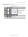
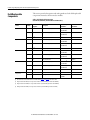
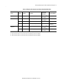
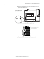
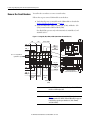
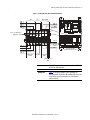
Installation Instructions
Removing and Replacing the
Line Interface Module
Internal Components
Catalog Numbers
2094-AL15S, 2094-AL25S, 2094-AL50S, 2094-AL75S,
2094-BL10S, 2094-BL25S, 2094-BL50S, 2094-BL75S,
2094-XL75S-C1, 2094-XL75S-C2, 2094-AL09, 2094-BL02
About This Publication
Topic
Page
About This Publication
1
Important User Information
2
Catalog Number Explanation
3
Field Replaceable Components
4
Remove/Replace the Front Cover
6
Remove the Circuit Breakers
8
Replace the Circuit Breakers
11
Remove the Auxiliary Contact
12
Replace the Auxiliary Contact
13
Remove and Replace the Fuse Block
13
Replace the (FB1) Fuses
14
Remove the Cooling Fan
14
Replace the Cooling Fan
16
Block Diagrams
17
Additional Resources
22
Use these instructions when replacing components internal to the Bulletin 2094
Line Interface Module (LIM) as specified in Field Replaceable Components on
page 4.
For installation information regarding equipment and accessories not included
here, refer to Additional Resources on page 22 or the information available for
those products.
2 Removing and Replacing the Line Interface Module Internal Components
Important User Information
Read this document and the documents listed in the additional resources section about installation, configuration, and operation of this
equipment before you install, configure, operate, or maintain this product. Users are required to familiarize themselves with installation
and wiring instructions in addition to requirements of all applicable codes, laws, and standards.
Activities including installation, adjustments, putting into service, use, assembly, disassembly, and maintenance are required to be
carried out by suitably trained personnel in accordance with applicable code of practice.
If this equipment is used in a manner not specified by the manufacturer, the protection provided by the equipment may be impaired.
In no event will Rockwell Automation, Inc. be responsible or liable for indirect or consequential damages resulting from the use or
application of this equipment.
The examples and diagrams in this manual are included solely for illustrative purposes. Because of the many variables and requirements
associated with any particular installation, Rockwell Automation, Inc. cannot assume responsibility or liability for actual use based on
the examples and diagrams.
No patent liability is assumed by Rockwell Automation, Inc. with respect to use of information, circuits, equipment, or software
described in this manual.
Reproduction of the contents of this manual, in whole or in part, without written permission of Rockwell Automation, Inc., is
prohibited.
Throughout this manual, when necessary, we use notes to make you aware of safety considerations.
WARNING: Identifies information about practices or circumstances that can cause an explosion in a hazardous environment,
which may lead to personal injury or death, property damage, or economic loss.
ATTENTION: Identifies information about practices or circumstances that can lead to personal injury or death, property
damage, or economic loss. Attentions help you identify a hazard, avoid a hazard, and recognize the consequence.
IMPORTANT
Identifies information that is critical for successful application and understanding of the product.
Labels may also be on or inside the equipment to provide specific precautions.
SHOCK HAZARD: Labels may be on or inside the equipment, for example, a drive or motor, to alert people that dangerous
voltage may be present.
BURN HAZARD: Labels may be on or inside the equipment, for example, a drive or motor, to alert people that surfaces may
reach dangerous temperatures.
ARC FLASH HAZARD: Labels may be on or inside the equipment, for example, a motor control center, to alert people to
potential Arc Flash. Arc Flash will cause severe injury or death. Wear proper Personal Protective Equipment (PPE). Follow ALL
Regulatory requirements for safe work practices and for Personal Protective Equipment (PPE).
Rockwell Automation Publication 2094-IN009D-EN-P - June 2015
Removing and Replacing the Line Interface Module Internal Components 3
Line interface module (LIM) catalog numbers and descriptions are listed in the
following table.
Catalog Number Explanation
Table 1 - LIM Catalog Numbers and Descriptions
Cat. No.
Input
Voltage
Current
Rating
2094-AL15S
230V
15 A
Description
2094-AL25S
25 A
· 230V AC auxiliary power output.
2094-AL50S
50 A
· 24V DC power output with 20 A current capacity.
2094-AL75S
75 A
· Customer-configurable branch-circuit
protection. This feature provides the
option for connecting CB2 and CB3 before
or after the main (CB1) disconnect.
Refer to the Line Interface Module Installation
Instructions, publication 2094-IN005, for
more information.
· Power to multiple Bulletin 2093 or 2094 power rails.
2094-BL10S
460V
10 A
2094-BL25S
25 A
2094-BL50S
50 A
2094-BL75S
75 A
· Branch circuit protection and disconnect when used with the
Variable Depth Rotary Mechanism (catalog number
140G-G-RVM12B).
· Internal 24V DC I/O line filter.
· Internal 230V AC control line filter.
· External (customer supplied) three-phase line filter.
2094-XL75S-C1
230/460V
75 A
110V AC auxiliary power input.
2094-XL75S-C2
230/460V
75 A
230V AC auxiliary power input.
2094-AL09
230V
20 A
· 24V DC power output with 8 A current capacity.
2094-BL02
460V
30 A
· Internal three-phase line filter.
· Internal 230V AC control line filter.
Rockwell Automation Publication 2094-IN009D-EN-P - June 2015
4 Removing and Replacing the Line Interface Module Internal Components
This section provides descriptions and catalog numbers for the field-replaceable
components internal to the line interface module.
Field Replaceable
Components
Table 2 - Field Replaceable Components
(2094-ALxxS, 2094-BLxxS, and 2094-XL75S-Cx LIM modules)
Cat. No.
Quantity
Reference
Designator
Description
Allen-Bradley
Part Number
Bussmann
Part Number
2094-ALxxS
1
CB2
Circuit Breaker, 2-pole, 20 A
1492-SP2D200(2)
1492-SPM2D200
—
1
CB3
Circuit Breaker, 2-pole, 16 A
1492-SP2C160(3)
1492-SPM2C160
—
2
FB1 (1)
Fuse, 10 A, Class CC
—
FNQ-R-10
Circuit Breaker, 2-pole, 4 A
1492-SP2D040(2)
—
2094-BLxxS
1
CB2
1492-SPM2D040
2094-XL75S-C1
1
CB3
Circuit Breaker, 3-pole, 6 A
1492-SP3C060(3)
1492-SPM3C060
—
2
FB1 (1)
Fuse, 3.5 A, Class CC
—
FNQ-R-3.5
Circuit Breaker, 2-pole, 20 A
1492-SP2D200(2)
—
1
CB2
1492-SPM2D200
2094-XL75S-C2
1
CB3
Circuit Breaker, 2-pole, 16 A
1492-SP2C160(3)
1492-SPM2C160
—
2
FB1 (1)
Fuse, 15 A, Class CC
—
FNQ-R-15
Circuit Breaker, 2-pole, 20 A
1492-SP2D200(2)
—
1
CB2
1492-SPM2D200
Common Module
Components
1
CB3
Circuit Breaker, 2-pole, 16 A
1492-SP2C160(3)
1492-SPM2C160
—
2
FB1 (1)
Fuse, 10 A, Class CC
—
FNQ-R-10
1
FB1
Fuse Block
1492-FB2C30-L
—
(4)
—
1
CB2A
Auxiliary Contact
(1) Fuses for FB1 are accessible from the front of each module. Refer to Figure 1 and Figure 2 for the location of FB1.
(2) CB2 (part number1492-SPxxxxx) is no longer available. It must be replaced with CB2 (part number 1492-SPMxxxxx).
(3) CB3 (part number 1492-SPxxxxx) is no longer available. It must be replaced with CB3 (part number 1492-SPMxxxxx).
(4) CB2A (part number1492-ASPH3) is no longer available. It must be replaced with CB2A (part number 189-ASCR3).
Rockwell Automation Publication 2094-IN009D-EN-P - June 2015
1492-ASPH3
189-ASCR3
Removing and Replacing the Line Interface Module Internal Components 5
Table 3 - Field Replaceable Components (2094-AL09 and 2094-BL02 LIM modules)
Cat. No.
Quantity
Reference
Designator
Description
Allen-Bradley
Part Number
Vendor Part Number
2094-AL09
1
CB1
Circuit Breaker, 3-phase, 25 A, 480V
1492-SP3D250(1)
1492-SPM3D250
—
2094-BL02
1
CB1
Circuit Breaker, 3-phase, 32 A, 480V
1492-SP3D320(1)
1492-SPM3D320
—
1
Finger Guard, Fan, Wire, 80 mm
—
8172 (Qual-Tek)
1
Fan, 80 mm (3.15 in.), 230V
—
UF80B23-BTH
(Mechatronics)
Common Module
Components
1
CB3
Circuit Breaker, 2-phase, 3 A, 480V
1492-SP2D030(2)
1492-SPM2D030
—
1
CB2
Circuit Breaker, 3-phase, 3 A, 480V
1492-SP3D030(3)
1492-SPM3D030
—
(1) CB1 (part number1492-SPxxxxx) is no longer available. It must be replaced with CB1 (part number 1492-SPMxxxxx).
(2) CB3 (part number1492-SPxxxxx) is no longer available. It must be replaced with CB3 (part number 1492-SPMxxxxx).
(3) CB2 (part number1492-SPxxxxx) is no longer available. It must be replaced with CB2 (part number 1492-SPMxxxxx).
Rockwell Automation Publication 2094-IN009D-EN-P - June 2015
6 Removing and Replacing the Line Interface Module Internal Components
Remove/Replace the Front
Cover
To perform all component removal/replacement procedures, you need to remove
power from the unit and remove the front cover to gain access to the internal
components. There are no tools needed to remove the front cover.
Follow these steps to remove the LIM module front cover.
1. Remove all input power to the LIM module.
ATTENTION: To avoid shock hazard or personal injury, assure
that all power has been removed before proceeding. This system
may have multiple sources of power. More than one disconnect
switch may be required to de-energize the system.
2. Allow five minutes for the 24V power supplies to completely discharge
before proceeding.
ATTENTION: To avoid hazard of electrical shock, verify that all
voltage on the capacitors has been discharged before
attempting to service, repair, or remove this unit. This product
contains stored energy devices. You should only attempt the
procedures in this document if you are qualified to do so and
familiar with solid-state control equipment and the safety
procedures in publication NFPA 70E.
3. Determine where to start disassembly.
For this LIM Module
Do this
2094-ALxxS, 2094 -BLxxS, or
2094-XL75S-Cx
Go to step 4.
2094-AL09 or 2094-BL02
Go to step 6.
4. Open the IO (IOL) connector access door.
5. Disconnect the IO (IOL) connector.
Rockwell Automation Publication 2094-IN009D-EN-P - June 2015
Removing and Replacing the Line Interface Module Internal Components 7
6. Locate the two bail fasteners (lower front cover) and rotate them one
quarter turn in either direction.
Line Interface Module, Front View
(2094-AL09 module is shown)
MAIN VAC
Closed
AUX VAC
BRAKE-I/O VAC
Open
Bail Fasteners
7. Slide the cover away and down from the LIM module.
Line Interface Module, Right-side View
(2094-AL09 module is shown)
8. To replace the LIM module front cover, reverse steps 6 and 7.
Rockwell Automation Publication 2094-IN009D-EN-P - June 2015
8 Removing and Replacing the Line Interface Module Internal Components
Remove the Circuit Breakers
You will need a screwdriver to remove circuit breakers.
Follow these steps to remove LIM module circuit breakers.
1. Verify that all power is removed from the LIM module as described in
Remove/Replace the Front Cover on page 6.
2. Locate the Main VAC (CB1), Control VAC (CB2), and Brake - I/O
(CB3) circuit breakers and Fuse Block (FB1).
Fuse block FB1 is present only in the 2094-ALxxS, 2094-BLxxS, and
2094-XL75S-Cx.
Figure 1 - Locating CB3, FB1, CB2A, and CB2 (2094-ALxxS and 2094-XL75S-Cx)
CB3
FB1
CB2 (assembly)
WIRE_10
WIRE_9
WIRE_11
WIRE_12
WIRE_7
WIRE_2
WIRE_1
1
3
1
3
1
3
12
14
Fuse access compartments
(pull down to open)
2
4
2
4
2
4
COIL_A2
11
WIRE_3
WIRE_4
WIRE_19
WIRE_18
WIRE_11
WIRE_12
Brake and I/O
(24V AC)
Fuse Block
Line Interface Module
(2094-ALxxS module is shown)
Control VAC
(CB2)
Auxiliary Contact
(CB2A)
IMPORTANT
Main VAC (CB1) in 2094-ALxxS, 2094-BLxxS, and 2090-XL75S-Cx
models is not field replaceable.
IMPORTANT
Figure 1 shows CB2 (part number 1492-SPMxxxxx) and
CB2A (part number 189-ASCR3). CB2 and CB2A will be in opposite
locations if the respective part numbers are (1492-SPxxxxx)
and (1492-ASPH3).
Rockwell Automation Publication 2094-IN009D-EN-P - June 2015
Removing and Replacing the Line Interface Module Internal Components 9
Figure 2 - Locating CB3, FB1, CB2A, and CB2 (2094-BLxxS)
CB3
FB1
CB2 (assembly)
WIRE_10
WIRE_9
WIRE_2
WIRE_1
WIRE_15
WIRE_11
WIRE_12
WIRE_7
1
3
5
1
3
1
3
12
14
Fuse access compartments
(pull down to open)
2
2
4
2
4
2
4
COIL_A2
11
WIRE_16
WIRE_3
WIRE_19
WIRE_18
WIRE_4
WIRE_11
WIRE_12
Brake and I/O
(24V AC)
Fuse Block
Line Interface Module
(2094-BLxxS module is shown)
Control VAC
(CB2)
Auxiliary Contact
(CB2A)
IMPORTANT
Main VAC (CB1) in 2094-ALxxS, 2094-BLxxS, and 2090-XL75S-Cx
models is not field replaceable.
IMPORTANT
Figure 2 shows CB2 (part number of 1492-SPMxxxxx) and
CB2A (part number 189-ASCR3). CB2 and CB2A will be in opposite
locations if the respective part numbers are (1492-SPxxxxx)
and (1492-ASPH3).
Rockwell Automation Publication 2094-IN009D-EN-P - June 2015
10 Removing and Replacing the Line Interface Module Internal Components
Figure 3 - Locating CB1, CB2_AUX, CB2, and CB3 (2094-AL09)
CB1
CB2
CB3
AUXSTAT_1
WIRE_2
L3
WIRE_6
WIRE_7
L2
WIRE_8
WIRE_9
WIRE_1
L1
1
3
5
1
3
5
1
3
2
4
6
2
4
6
2
4
WIRE_14
WIRE_16
WIRE_3
WIRE_4
WIRE_5
WIRE_13
WIRE_15
230VAC_L1
230VAC_L2
AUXSTAT_2
Main VAC
(230/460V AC)
Control VAC
(CB2)
Line Interface Module
(2094-AL09 module is shown)
Brake and I/O
(24V AC)
Auxiliary Contact
(CB2_AUX)
Figure 4 - Locating CB1, CB2_AUX, CB2, and CB3 (2094-BL02)
CB1
CB2
CB3
AUXSTAT_1
WIRE_2
L3
WIRE_8
WIRE_9
L2
WIRE_10
WIRE_11
WIRE_1
L1
1
3
5
1
3
5
1
3
2
4
6
2
4
6
2
4
WIRE_5
WIRE_6
WIRE_7
WIRE_16
WIRE_18
WIRE_15
WIRE_17
230VAC_L1
230VAC_L2
AUXSTAT_2
Main VAC
(230/460V AC)
Control VAC
(CB2)
Brake and I/O
(24V AC)
Auxiliary Contact
(CB2_AUX)
Rockwell Automation Publication 2094-IN009D-EN-P - June 2015
Line Interface Module
(2094-BL02 module is shown)
Removing and Replacing the Line Interface Module Internal Components 11
3. Remove wiring from the top and bottom circuit breaker terminals and
label each wire if not already done.
4. Using a screwdriver, release the spring latch beneath each circuit breaker
while pulling the breaker up and away from the DIN rail.
13.0 mm
(0.51 in.)
Removing/inserting
wires
Turn screw clockwise to tighten,
counter-clockwise to loosen.
Releasing the
spring latch (1)
(1)
Replace the Circuit Breakers
You may need two screwdrivers to release the control circuit breaker (CB2) and auxiliary contact latch on 2094-ALxxS, 2094-BLxxS,
and 2094-XL75S modules at the same time.
You will need a screwdriver to replace circuit breakers.
IMPORTANT
When replacing CB2 (part number 1492-SPxxxxx) with the
replacement CB2 indicated in Table 2, CB2A will also need to be
replaced. See Table 2 for the CB2A replacement part number.
Follow these steps to replace LIM module circuit breakers.
1. Verify that all power is removed from the LIM module as described in
Remove/Replace the Front Cover on page 6.
2. Insert the screwdriver (as shown in the figure above) and release the spring
latch while setting the replacement breaker into position on the DIN rail.
For replacement component part numbers, refer to Table 2 and Table 3 on
page 4.
3. Remove the screwdriver to set the latch.
4. Reconnect the circuit breaker wiring. Torque set screws to
2.3…2.5 N•m (20…22 lb•in).
Refer to the wire labels (as shown in the figures beginning on
page 8) and/or Block Diagrams (beginning on page 17) when
reconnecting the circuit breaker wiring.
Rockwell Automation Publication 2094-IN009D-EN-P - June 2015
12 Removing and Replacing the Line Interface Module Internal Components
Remove the Auxiliary
Contact
You will need a screwdriver to remove the CB2A auxiliary contact from the CB2
control circuit breaker.
IMPORTANT
This procedure applies to only the auxiliary contact in 2094-ALxxS,
2094-BLxxS, and 2094-XL75S-Cx LIM modules. Other LIM modules do not
have an auxiliary contact.
IMPORTANT
This procedure applies to only the auxiliary contact CB2A (189-ASCR3).
Previous versions of the auxiliary contact CB2A (1492-ASPH3) must be
replaced with a new circuit breaker CB2 and a new auxiliary contact CB2A.
Follow these steps to remove the auxiliary contact.
1. Verify that all power is removed from the LIM module as described in
Remove/Replace the Front Cover on page 6.
2. Remove the CB2 assembly (refer to Remove the Circuit Breakers
beginning on page 8 for instructions).
3. Locate the clip fastener on the bottom side of the auxiliary contact and use
a screwdriver to gently pry the clip downward to release the contact.
Top clip pivots in slot.
1492-SP
Circuit Breaker (CB2)
Pins align in holes.
189-ASCR3
Auxiliary Contact (CB2A)
Bottom clip latches when contact
and circuit breaker are pressed together
(releases when gently pried apart).
Hang top clip in slot and
snap together when replacing.
Release clip and pivot apart to remove.
4. Go to Replace the Auxiliary Contact on page 13.
Rockwell Automation Publication 2094-IN009D-EN-P - June 2015
Removing and Replacing the Line Interface Module Internal Components 13
Replace the Auxiliary Contact
You will need a screwdriver to replace the CB2A auxiliary contact, which is
connected to the CB2 control circuit breaker. For replacement component part
numbers, refer to Table 2 and Table 3 on page 4.
IMPORTANT
This procedure applies to only the auxiliary contact in 2094-ALxxS,
2094-BLxxS, and 2094-XL75S-Cx LIM modules. Other LIM modules do not
have an auxiliary contact.
IMPORTANT
This procedure applies to only the auxiliary contact CB2A (189-ASCR3).
Previous versions of the auxiliary contact CB2A (1492-ASPH3) must be
replaced with a new circuit breaker CB2 and a new auxiliary contact CB2A.
Follow these steps to replace the auxiliary contact.
1. Verify that all power is removed from the LIM module as described in
Remove/Replace the Front Cover on page 6.
2. Hook the replacement auxiliary contact in the top slot (refer to the figure
on page 12 for an illustration).
3. Align pins and press CB2A and CB2 together until the bottom clip
latches.
You will hear an audible click and the sides of the breakers will be flush.
4. Replace the CB2 assembly.
Refer to Replace the Circuit Breakers on page 11 for instructions.
Remove and Replace the
Fuse Block
You will need a screwdriver to remove and replace the fuse block from the DIN
rail.
IMPORTANT
This procedure applies only to FB1 in 2094-ALxxS, 2094-BLxxS, or
2094-XL75S-Cx LIM modules. Other LIM modules do not have a field
replaceable fuse block.
Follow these steps to remove and replace fuse block FB1.
1. Verify that all power is removed from the LIM module as described in
Remove/Replace the Front Cover on page 6.
2. Locate FB1 inside your LIM module.
Refer to the Figure 7 and Figure 8 for the location of FB1.
3. Follow the circuit breaker removal and replacement procedures beginning
on page 8 to remove fuse block FB1 from the DIN rail.
Rockwell Automation Publication 2094-IN009D-EN-P - June 2015
14 Removing and Replacing the Line Interface Module Internal Components
Replace the (FB1) Fuses
No tools are required to replace FB1 fuses.
TIP
IMPORTANT
It is not necessary to remove the LIM module front cover to access FB1
fuses.
This procedure applies only to 2094-ALxxS, 2094-BLxxS, or 2094-XL75S-Cx
LIM modules. There are no field replaceable fuses in other LIM modules.
Follow these steps to replace FB1 fuses.
1. Verify that all power is removed from the LIM module as described in
Remove/Replace the Front Cover on page 6.
2. Locate FB1 on the front of your LIM module.
Refer to the Figure 7 and Figure 8 for the location of FB1.
3. Pull down on the FB1 access compartments and replace fuses.
4. Push the access compartments closed.
Remove the Cooling Fan
Whenever input power is applied to the 2094-BL02 LIM module, the cooling
fan will operate (even if the LIM module circuit breakers CB1, CB2, and CB3
are turned off ). Fan life is approximately 20,000 hours.
ATTENTION: This procedure applies only to 2094-BL02 LIM modules.
To avoid damage to your 2094-BL02 LIM module, make sure the cooling fan
is operational. Damaged or inoperable fans will cause the 2094-BL02 LIM
module to fail.
You will need a #2 Phillips screwdriver to remove the cooling fan.
Follow these steps to remove the 2094-BL02 LIM module cooling fan.
1. Verify that all power is removed from the LIM module as described in
Remove/Replace the Front Cover on page 6.
2. Determine your ease of access to the cooling fan.
If access to the fan is
Then
Limited (insufficient clearance to access fan
screws)
Remove the LIM module from the cabinet (1) before
proceeding to step 3.
Not limited (adequate clearance to access fan
screws)
Go to step 3.
(1) For drive system component removal/replacement procedures, refer to the appropriate servo-drive user manual in
Additional Resources on page 22.
Rockwell Automation Publication 2094-IN009D-EN-P - June 2015
Removing and Replacing the Line Interface Module Internal Components 15
3. Remove the four Phillips screws that hold the finger guard and fan in
place.
2094-BL02
Line Interface Module
4. Set the finger guard aside.
5. Pull the fan away from the LIM module and disconnect the power cord.
2094-BL02
Line Interface Module
6. Go to Replace the Cooling Fan on page 16.
Rockwell Automation Publication 2094-IN009D-EN-P - June 2015
16 Removing and Replacing the Line Interface Module Internal Components
Replace the Cooling Fan
You will need a #2 Phillips screwdriver to replace the cooling fan.
Follow these steps to replace the LIM cooling fan.
1. Verify that all power is removed from the LIM module as described in
Remove/Replace the Front Cover on page 6.
2. Connect the replacement fan to the power cord and place the fan back
inside the LIM module.
ATTENTION: To avoid damage to equipment make sure the fan
is positioned so that airflow is in an outward direction (arrow on
fan points away from the LIM module).
3. Replace the finger guard and the four Phillips screws. Torque screws to 0.9
N•m (8 lb•in).
ATTENTION: To avoid injury or damage to equipment, ensure
the finger guard is in place before replacing the four screws.
Rockwell Automation Publication 2094-IN009D-EN-P - June 2015
IPL
OPL
4
3
BB1
BB2
BB3
BB4
BB5
BB6
PE
L3'
L2'
L1'
Pin 1
Pin 2
Pin 3
Pin 4
PE
L3
L2
L1
IPL: VAC LINE
4
3
2
1
IPL
Pin 1
Pin 2
Pin 3
Pin 4
OPL: VAC LOAD
4
3
2
1
OPL
5
4
3
2
1
J4 P4
WIRE_10
WIRE_2
WIRE_9
WIRE_1
WIRE_15
B
CR1
1
2
N/C
12 22 32 42
54
WIRE_1
WIRE_9
WIRE_2
WIRE_10
ALRM_COM
L3
L2
L1
M
Rockwell Automation Publication 2094-IN009D-EN-P - June 2015
4 WIRE_12
3
2
4
3
ALRM_M 1
ALRM_B
3
5
1
CB 3
2 WIRE_11
1
FB1
CB1 (Bulletin 140U)
AL
1c
4
6
5
2
3
1
4
6
A2
1
14
2
4
1
3
LF 2
COIL_A2
WIRE_7
CB 2
12
11
L1
L2
L3
N
1
2
3
4
6
7
8
9
10
L1'
L2'
L3'
N'
PE
Three-phase, 1-Stage
Line Filter (460VAC)
WIRE_8
53
ALRM_M
ALRM_COM
ALRM_B
N/C
11 21 31 41
A1
CONSTAT_54
L1'
WIRE_19
WIRE_18
LF 1
WIRE_8
PE
L1
L2
L1
L2
PS1
3
4
5
L1'
L2'
PE
20 A Power Supply
1
2
Single-phase, 1-Stage
Line Filter (230VAC)
CONSTAT_53
CONSTAT_31
CONSTAT_21
CONSTAT_11
A1
100-JE
E2
E1
COIL_E2
COIL_E1
COIL_A2
CONSTAT_32
L2'
(P4) J4_B
1
2
3
4
5
CONSTAT_22
CONSTAT_12
L3'
24+
2424+
24-
IO_PWR1
IO_COM1
IO_PWR2
IO_COM2
AUX_L2
AUX_L1
CTRL1
CTRL2
ALRM_M
COIL_E2
CONSTAT_54
CONSTAT_32
CONSTAT_22
CONSTAT_12
ALRM_COM
ALRM_B
COIL_E1
CONSTAT_53
CONSTAT_31
CONSTAT_21
CONSTAT_11
1
2
3
4
5
4
3
2
1
J2
J3
6
5
4
3
2
1
P1L
CPL
2
1
4
3
2
1
P2L
1
2
3
4
5
6
7
8
9
10
11
12
13
14
15
16
17
18
19
20
21
IOL
24V Status LED
Interface PCB
1
2
3
4
5
6
P1L
1
2
CPL
1
2
3
4
P2L
21
1
IOL
20
2
IO_PWR1
IO_COM1
IO_PWR1
IO_COM1
IO_PWR1
IO_COM1
COIL_E1
COIL_E2
ALRM_M
SHIELD
ALRM_B
ALRM_COM
CONSTAT_11
CONSTAT_12
CONSTAT_21
CONSTAT_22
CONSTAT_31
CONSTAT_32
CONSTAT_53
CONSTAT_54
SHIELD
AUX1_L2
AUX1_L1
AUX2_L2
AUX2_L1
CTRL 2
CTRL 1
Pin 6
Pin 5
Pin 4
Pin 3
Pin 2
Pin 1
IO_COM2
IO_PWR2
IO_COM2
IO_PWR2
IO_COM2
IO_PWR2
P1L: BRAKE AND I/O OUTPUT
Pin 2
Pin 1
CPL: CONTROL PWR OUTPUT
Pin 4
Pin 3
Pin 2
Pin 1
P2L: AUXILIARY PWR OUTPUT
Pin 1
Pin 2
Pin 3
Pin 4
Pin 5
Pin 6
Pin 7
Pin 8
Pin 9
Pin 10
Pin 11
Pin 12
Pin 13
Pin 14
Pin 15
Pin 16
Pin 17
Pin 18
Pin 19
Pin 20
Pin 21
IOL: STATUS I/O
Block Diagrams
2
1
4
3
2
1
Interface PCB
Removing and Replacing the Line Interface Module Internal Components 17
Figure 5 through Figure 9 are block diagrams for the Bulletin 2094 LIM
modules.
Figure 5 - LIM Module Block Diagram (2094-ALxxS)
IPL
OPL
4
3
2
1
4
3
2
1
BB1
BB2
BB3
BB4
BB5
BB6
Pin 1
Pin 2
Pin 3
Pin 4
IPL: VAC LINE
4
3
2
1
IPL
Pin 1
Pin 2
Pin 3
Pin 4
OPL: VAC LOAD
4
3
2
1
OPL
PE
L3'
L2'
L1'
PE
L3
L2
L1
Interface PCB
J4 P4
5
4
3
2
1
L3
L1
L1
L2
L2
B
CR1
2
N/C
12 22 32 42
54
ALRM_COM
L3
L2
L1
M
Rockwell Automation Publication 2094-IN009D-EN-P - June 2015
4
6 WIRE_4
5
WIRE_2
WIRE_16
WIRE_3
3
2
WIRE_1
CB 3
460V :: 230V
750VA
1
1
4
3
ALRM_B 1
ALRM_M 1
TX1
6
4
2
3
5
WIRE_15
2
1
FB1
CB1 (Bulletin 140U)
AL
1c
5
3
1
4
6
A2
4
3
12
1
LF 2
CB 2
14
2
11
WIRE_7
L1
L2
L3
N
1
2
3
4
6
7
8
9
10
L1'
L2'
L3'
N'
PE
Three-phase, 1-Stage
Line Filter (460VAC)
WIRE_8
53
ALRM_M
ALRM_COM
ALRM_B
N/C
11 21 31 41
E2
E1
WIRE_5
WIRE_6
WIRE_17
WIRE_19
LF 1
COIL_E2
COIL_E1
L1
L2
L3
PE
L1
L2
PS1
3
4
5
L1'
L2'
PE
20 A Power Supply
1
2
Single-phase, 1-Stage
Line Filter (230VAC)
CONSTAT_53
CONSTAT_31
CONSTAT_21
CONSTAT_11
A1
100-JE
WIRE_18
COIL_A2
A1
CONSTAT_54
L1'
COIL_A2
CONSTAT_32
L2'
(P4) J4_B
1
2
3
4
5
CONSTAT_22
CONSTAT_12
L3'
24+
2424+
24-
IO_PWR1
IO_COM1
IO_PWR2
IO_COM2
1
2
3
4
6
5
4
3
2
1
P1L
1
2
3
4
5
6
P1L
1
2
CPL
AUX_L2
AUX_L1
2
3
4
P2L
1
CPL
2
1
4
3
2
1
P2L
21
1
IOL
CTRL1
CTRL2
ALRM_M
COIL_E2
CONSTAT_54
CONSTAT_32
CONSTAT_22
CONSTAT_12
ALRM_COM
ALRM_B
COIL_E1
CONSTAT_53
CONSTAT_31
CONSTAT_21
CONSTAT_11
1
2
3
4
5
6
7
8
9
10
11
12
13
14
15
16
17
18
19
20
21
IOL
24V Status LED
Interface PCB
20
2
IO_PWR1
IO_COM1
IO_PWR1
IO_COM1
IO_PWR1
IO_COM1
COIL_E1
COIL_E2
ALRM_M
SHIELD
ALRM_B
ALRM_COM
CONSTAT_11
CONSTAT_12
CONSTAT_21
CONSTAT_22
CONSTAT_31
CONSTAT_32
CONSTAT_53
CONSTAT_54
SHIELD
AUX1_L2
AUX1_L1
AUX2_L2
AUX2_L1
CTRL 2
CTRL 1
Pin 6
Pin 5
Pin 4
Pin 3
Pin 2
Pin 1
IO_COM2
IO_PWR2
IO_COM2
IO_PWR2
IO_COM2
IO_PWR2
P1L: BRAKE AND I/O OUTPUT
Pin 2
Pin 1
CPL: CONTROL PWR OUTPUT
Pin 4
Pin 3
Pin 2
Pin 1
P2L: AUXILIARY PWR OUTPUT
Pin 1
Pin 2
Pin 3
Pin 4
Pin 5
Pin 6
Pin 7
Pin 8
Pin 9
Pin 10
Pin 11
Pin 12
Pin 13
Pin 14
Pin 15
Pin 16
Pin 17
Pin 18
Pin 19
Pin 20
Pin 21
IOL: STATUS I/O
18 Removing and Replacing the Line Interface Module Internal Components
Figure 6 - LIM Module Block Diagram (2094-BLxxS)
APL
IPL
OPL
2
1
4
3
2
1
4
3
2
1
PE
L3
L2
L1
BB4
BB5
BB6
PE
L3'
L2'
L1'
BB1
BB2
BB3
J4 P4
5
4
3
2
1
APL: AUXILIARY PWR INPUT
Pin 1
L2/N
Pin 2
L1
2
1
APL
Pin 1
Pin 2
Pin 3
Pin 4
IPL: VAC LINE
4
3
2
1
IPL
Pin 1
Pin 2
Pin 3
Pin 4
OPL: VAC LOAD
4
3
2
1
OPL
Interface PCB
1
B
1
2
N/C
12 22 32 42
54
WIRE_1
WIRE_9
WIRE_2
WIRE_10
ALRM_COM
L3
L2
L1
M
Rockwell Automation Publication 2094-IN009D-EN-P - June 2015
4
6
3
5
WIRE_2
2
1
WIRE_4
WIRE_3
ALRM_M 1
ALRM_B
1
CB 3
4 WIRE_12
2 WIRE_11
6
4
2
3
5
WIRE_1
3
1
FB1
CB1 (Bulletin 140U)
AL
1c
5
3
4
6
A2
L1
L2
L3
N
1
2
3
4
6
7
8
9
10
L1'
L2'
L3'
N'
PE
Three-phase, 1-Stage
Line Filter (460VAC)
4
3
12
1
LF 2
CB 2
14
2
11
WIRE_7
WIRE_8
COIL_A2
53
ALRM_M
ALRM_COM
ALRM_B
N/C
11 21 31 41
A1
100-JE
LF 1
PE
L1
L2
WIRE_18
L1
WIRE_19
L2
PS1
3
4
5
L1'
L2'
PE
20 A Power Supply
1
2
Single-phase, 1-Stage
Line Filter (230VAC)
CONSTAT_53
CONSTAT_31
CONSTAT_21
CONSTAT_11
WIRE_5
WIRE_6
A1
E2
E1
COIL_E2
COIL_E1
CONSTAT_54
L1'
CR1
CONSTAT_32
L2'
COIL_A2
CONSTAT_22
CONSTAT_12
L3'
24+
2424+
24-
IO_PWR1
IO_COM1
IO_PWR2
IO_COM2
1
2
3
4
J2
6
5
4
3
2
1
P1L
1
2
3
4
5
6
P1L
1
2
CPL
CPL
2
1
1
2
3
4
P2L
AUX_L2
AUX_L1
J3
4
3
2
1
P2L
21
1
IOL
CTRL1
CTRL2
ALRM_M
COIL_E2
CONSTAT_54
CONSTAT_32
CONSTAT_22
CONSTAT_12
ALRM_COM
ALRM_B
COIL_E1
CONSTAT_53
CONSTAT_31
CONSTAT_21
CONSTAT_11
1
2
3
4
5
6
7
8
9
10
11
12
13
14
15
16
17
18
19
20
21
IOL
24V Status LED
Interface PCB
20
2
IO_PWR1
IO_COM1
IO_PWR1
IO_COM1
IO_PWR1
IO_COM1
COIL_E1
COIL_E2
ALRM_M
SHIELD
ALRM_B
ALRM_COM
CONSTAT_11
CONSTAT_12
CONSTAT_21
CONSTAT_22
CONSTAT_31
CONSTAT_32
CONSTAT_53
CONSTAT_54
SHIELD
AUX1_L2
AUX1_L1
AUX2_L2
AUX2_L1
CTRL 2
CTRL 1
Pin 6
Pin 5
Pin 4
Pin 3
Pin 2
Pin 1
IO_COM2
IO_PWR2
IO_COM2
IO_PWR2
IO_COM2
IO_PWR2
P1L: BRAKE AND I/O OUTPUT
Pin 2
Pin 1
CPL: CONTROL PWR OUTPUT
Pin 4
Pin 3
Pin 2
Pin 1
P2L: AUXILIARY PWR OUTPUT
Pin 1
Pin 2
Pin 3
Pin 4
Pin 5
Pin 6
Pin 7
Pin 8
Pin 9
Pin 10
Pin 11
Pin 12
Pin 13
Pin 14
Pin 15
Pin 16
Pin 17
Pin 18
Pin 19
Pin 20
Pin 21
IOL: STATUS I/O
Removing and Replacing the Line Interface Module Internal Components 19
Figure 7 - LIM Module Block Diagram (2094-XL75S-Cx)
IPL
OPL
1
2
3
4
1
2
3
4
PE
L3'
L2'
L1'
Pin 1
Pin 2
Pin 3
Pin 4
PE
L3
L2
L1
IPL: VAC LINE INPUT
Pin 4
Pin 3
Pin 2
Pin 1
OPL: VAC LOAD OUTPUT
L3_IN
L2_IN
L1_IN
5
L3
L2
L1
LF2
L2'
L2
5
Rockwell Automation Publication 2094-IN009D-EN-P - June 2015
4
6
5
21
22
3
4
2
11
12
2 CB2_AUX
CB2
CB3
1
2
1
3
1
3
4
31
32
41
42
PE
L2
L1
PE
L2
L1
CONSTAT_11
CONSTAT_21
CONSTAT_31
PS1
2 A Power Supply
PS2
6 A Power Supply
D1
COIL_A1
CONSTAT_41
A1
A2
24-
24+
24-
24+
MBRK_COM
MBRK_PWR
IO_COM
IO_PWR
L2/N
L1
COIL_A2
COIL_A1
IO_PWR
IO_COM
CONSTAT_42
CONSTAT_41
CONSTAT_32
CONSTAT_31
CONSTAT_22
CONSTAT_21
CONSTAT_12
CONSTAT_11
1
2
CPL
4
3
2
1
PSL
19
PE
L1'
L1
LF1
PE
L3'
L2'
L1'
Three-phase, 1-Stage
Line Filter (460VAC)
CR1
6
COIL_A2
IOL
MBRK_PWR
MBRK_COM
MBRK_PWR
MBRK_COM
Pin 1
Pin 2
L2/N
L1
CPL: CONTROL POWER
Pin 1
Pin 2
Pin 3
Pin 4
PSL: I/O 24V DC OUTPUT
IOL: STATUS I/O
Pin 1
N/C
Pin 2
N/C
Pin 3
N/C
Pin 4
COIL_A2
Pin 5
N/C
Pin 6
CONSTAT_12
Pin 7
CONSTAT_22
Pin 8
CONSTAT_32
Pin 9
CONSTAT_42
Pin 10
N/C
Pin 11
N/C
Pin 12
N/C
Pin 13
COIL_A1
Pin 14
N/C
Pin 15 CONSTAT_11
Pin 16 CONSTAT_21
Pin 17 CONSTAT_31
Pin 18 CONSTAT_41
Pin 19
N/C
Pin 20
IO_COM
Pin 21
IO_COM
Pin 22
IO_COM
Pin 23
N/C
Pin 24
IO_PWR
Pin 25
IO_PWR
Pin 26
IO_PWR
24V Status LEDs
9
18
26
Single-phase, 1-Stage
Line Filter (230VAC)
4
6
3
CB1
2
1
L1_OUT
L2_OUT
L3_OUT
CONSTAT_42
CONSTAT_32
CONSTAT_22
CONSTAT_12
20 Removing and Replacing the Line Interface Module Internal Components
Figure 8 - LIM Module Block Diagram (2094-AL09)
1
10
IPL
OPL
4
3
2
1
4
3
2
1
PE
L3'
L2'
L1'
Pin 4
Pin 3
Pin 2
Pin 1
L3_IN
L2_IN
L1_IN
6
5
Rockwell Automation Publication 2094-IN009D-EN-P - June 2015
Cooling Fan
LF2
L2'
L2
FAN_2
FAN_1
L3
L2
L1
LF1
PE
L3'
L2'
L1'
Three-phase, 1-Stage
Line Filter (460VAC)
CR1
100S-C85
5
6
3
4
5
6
4
31
32
3
21
22
2 CB2_AUX
CB2
CB3
4
2
11
12
1
3
1
1
2
41
42
PE
L2
L1
PE
L2
L1
CONSTAT_11
CONSTAT_21
CONSTAT_31
PS1
2 A Power Supply
PS2
6 A Power Supply
D1
COIL_A1
CONSTAT_41
A1
A2
COIL_A2
CONSTAT_42
24-
24+
24-
24+
IO_PWR
MBRK_COM
MBRK_PWR
IO_COM
L2/N
L1
COIL_A2
COIL_A1
IO_PWR
IO_COM
CONSTAT_42
CONSTAT_41
CONSTAT_32
CONSTAT_31
CONSTAT_22
CONSTAT_21
CONSTAT_12
CONSTAT_11
PSL
1
2
CPL
4
3
2
1
IOL
MBRK_PWR
MBRK_COM
MBRK_PWR
MBRK_COM
Pin 1
Pin 2
L2/N
L1
CPL: CONTROL POWER
Pin 1
Pin 2
Pin 3
Pin 4
PSL: I/O 24V DC OUTPUT
IOL: STATUS I/O
Pin 1
N/C
Pin 2
N/C
Pin 3
N/C
Pin 4
COIL_A2
Pin 5
N/C
Pin 6
CONSTAT_12
Pin 7
CONSTAT_22
Pin 8
CONSTAT_32
Pin 9
CONSTAT_42
Pin 10
N/C
Pin 11
N/C
Pin 12
N/C
Pin 13
COIL_A1
Pin 14
N/C
Pin 15 CONSTAT_11
Pin 16 CONSTAT_21
Pin 17 CONSTAT_31
Pin 18 CONSTAT_41
Pin 19
N/C
Pin 20
IO_COM
Pin 21
IO_COM
Pin 22
IO_COM
Pin 23
N/C
Pin 24
IO_PWR
Pin 25
IO_PWR
Pin 26
IO_PWR
24V Status LEDs
19
PE
L1'
L1
Single-phase, 1-Stage
Line Filter (230VAC)
4
3
CB1
2
1
L1_OUT
L2_OUT
L3_OUT
CONSTAT_32
CONSTAT_22
CONSTAT_12
9
18
26
TX1
460V to 230V
750VA XFMR
PE
L3
L2
L1
IPL: VAC LINE INPUT
Pin 1
Pin 2
Pin 3
Pin 4
OPL: VAC LOAD OUTPUT
Removing and Replacing the Line Interface Module Internal Components 21
Figure 9 - LIM Module Block Diagram (2094-BL02)
1
10
22 Removing and Replacing the Line Interface Module Internal Components
Additional Resources
These documents contain additional information concerning related Rockwell
Automation products.
Resource
Description
Kinetix 2000 Multi-axis Servo Drives User Manual,
publication 2093-UM001
Mounting, wiring, setup with Studio 5000 Logix Designer® application, applying power, and
troubleshooting information with appendices to support firmware upgrades and common bus
applications.
Kinetix 6000 Multi-axis Servo Drives User Manual,
publication 2094-UM001
Kinetix 7000 High Power Servo Drives User Manual,
publication 2099-UM001
Line Interface Module Installation Instructions,
publication 2094-IN005
Mounting, wiring, applying power, troubleshooting information, and product specifications for
the Bulletin 2094 LIM modules.
2094 Mounting Brackets Installation Instructions,
publication 2094-IN008
Information on installing 2094 mounting brackets for use with 2094 power rails or LIM modules.
Kinetix Motion Control Selection Guide,
publication GMC-SG001
Specifications, motor/servo-drive system combinations, and accessory items for Kinetix Motion
Control products.
Kinetix Motion Accessories Specifications,
publication GMC-TD004
Product specifications for Bulletin 2090 motor and interface cables, low-profile connector kits,
drive power components, and other servo drive accessory items.
Motion Analyzer Sizing and Selection Tool,
https://motionanalyzer.rockwellautomation.com
Online tool for sizing and selecting servo drive systems with the compatible motor, actuator, and
accessories required for each axis.
Resistive Brake Module Installation Instructions,
publication 2090-IN009
Information on the installation and wiring of the Bulletin 2090 Resistive Brake Module (RBM).
System Design for Control of Electrical Noise Reference Manual, publication
GMC-RM001
Information, examples, and techniques designed to minimize system failures caused by electrical
noise.
EMC Noise Management DVD, publication GMC-SP004
Understanding the Machinery Directive, publication SHB-900
A road map to CE marking and safety-related control product applications.
Rockwell Automation Product Certification website,
http://www.ab.com
For declarations of conformity (DoC) currently available from Rockwell Automation.
National Electrical Code, published by the National Fire Protection Association of
Boston, MA
An article on wire sizes and types for grounding electrical equipment.
Allen-Bradley Industrial Automation Glossary, publication AG-7.1
A glossary of industrial automation terms and abbreviations.
You can view or download publications at
http://literature.rockwellautomation.com. To order paper copies of technical
documentation, contact your local Rockwell Automation distributor or sales
representative.
Rockwell Automation Publication 2094-IN009D-EN-P - June 2015
Removing and Replacing the Line Interface Module Internal Components 23
Notes:
Rockwell Automation Publication 2094-IN009D-EN-P - June 2015
Rockwell Automation Support
Rockwell Automation provides technical information on the Web to assist you in using its products.
At http://www.rockwellautomation.com/support you can find technical and application notes, sample code, and links to
software service packs. You can also visit our Support Center at https://rockwellautomation.custhelp.com/ for software
updates, support chats and forums, technical information, FAQs, and to sign up for product notification updates.
In addition, we offer multiple support programs for installation, configuration, and troubleshooting. For more
information, contact your local distributor or Rockwell Automation representative, or visit
http://www.rockwellautomation.com/services/online-phone.
Installation Assistance
If you experience a problem within the first 24 hours of installation, review the information that is contained in this
manual. You can contact Customer Support for initial help in getting your product up and running.
United States or Canada
1.440.646.3434
Outside United States or Canada
Use the Worldwide Locator at http://www.rockwellautomation.com/rockwellautomation/support/overview.page, or contact your local
Rockwell Automation representative.
New Product Satisfaction Return
Rockwell Automation tests all of its products to help ensure that they are fully operational when shipped from the
manufacturing facility. However, if your product is not functioning and needs to be returned, follow these procedures.
United States
Contact your distributor. You must provide a Customer Support case number (call the phone number above to obtain one) to your
distributor to complete the return process.
Outside United States
Please contact your local Rockwell Automation representative for the return procedure.
Documentation Feedback
Your comments will help us serve your documentation needs better. If you have any suggestions on how to improve this
document, complete this form, publication RA-DU002, available at http://www.rockwellautomation.com/literature/.
Rockwell Automation maintains current product environmental information on its website at
http://www.rockwellautomation.com/rockwellautomation/about-us/sustainability-ethics/product-environmental-compliance.page.
Allen-Bradley, Kinetix, Studio 5000 Logix Designer, Rockwell Software, and Rockwell Automation are trademarks of Rockwell Automation, Inc
Trademarks not belonging to Rockwell Automation are property of their respective companies.
Rockwell Otomasyon Ticaret A.Ş., Kar Plaza İş Merkezi E Blok Kat:6 34752 İçerenköy, İstanbul, Tel: +90 (216) 5698400
Publication 2094-IN009D-EN-P - June 2015
Supersedes Publication 2094-IN009C-EN-P - May 2008
Copyright © 2015 Rockwell Automation, Inc. All rights reserved. Printed in the U.S.A.