1
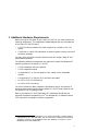
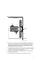
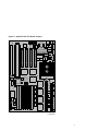
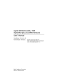
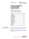
dt
Alpha PCI 64–275
Read Me First
Order Number: EK–ALPPI–CL. A01
Revision/Update Information:
Digital Equipment Corporation
Maynard, Massachusetts
This is a new document.
April 1996
While Digital believes the information included in this publication is correct as of the date of
publication, it is subject to change without notice.
Digital Equipment Corporation grants to the purchaser of Alpha microprocessor or peripheral
sample designs and design tools a fully paid up, non-exclusive, irrevocable, perpetual and
worldwide license to copy, use, reproduce or have developed products based on or that incorporate
all, or a portion of the sample board designs and to manufacture, have manufactured, market,
sell, lease, license or otherwise distribute such products based on, or that incorporate the sample
Digital Alpha microprocessor or peripheral products.
© Digital Equipment Corporation 1995, 1996.
Printed in U.S.A.
All rights reserved.
DEC, DECchip, Digital, EtherWORKS, the AlphaGeneration design mark, and the DIGITAL logo
are trademarks of Digital Equipment Corporation.
Digital Semiconductor is a Digital Equipment Corporation business.
Digital UNIX Version 3.2 for Alpha is a UNIX 93 branded product.
CompuServe is a registered trademark of CompuServe, Inc.
Microsoft is a registered trademark and Windows NT is a trademark of Microsoft Corporation.
OSF/1 is a registered trademark of Open Software Foundation, Inc.
PAL and MACH are trademarks of Advanced Micro Devices, Inc.
PostScript is a registered trademark of Adobe Systems, Incorporated.
Powerview and Viewlogic are registered trademarks of Viewlogic Systems, Incorporated.
PS/2 is a registered trademark of International Business Machines Corporation.
UNIX is a registered trademark in the United States and other countries licensed exclusively
through X/Open Limited.
All other trademarks and registered trademarks are the property of their respective owners.
1 Introduction to the Alpha PCI 64–275
The Alpha PCI 64–275 is a motherboard containing an Alpha 21064A
microprocessor. The board supports the Microsoft Windows NT operating
system through firmware in a flash ROM. In addition, the firmware contains
a mini-debugger to assist you as you install the Alpha PCI 64–275 in your
application.
Note
The Windows NT operating system is not included and must be
purchased separately.
2 Alpha PCI 64–275 Documentation
Table 1 provides a list of the documentation available for the Alpha PCI
64–275.
Table 1 Associated Alpha PCI 64–275 Motherboard Documentation
Title
Order Number
Alpha PCI 64–275 Motherboard Documentation
Alpha PCI 64–275 User’s Manual
EK–AL275–UM1
Alpha PCI 64–275 Design Guide
EK–AL275–UG1
Alpha 21064A Documentation
Alpha Architecture Handbook
EC–QD2KA–TE
Alpha 21064A Microprocessor Product Brief
EC–QH0RA–TE
Alpha 21064A–233, –275 Microprocessor Data Sheet
EC–QFGKA–TE
Alpha 21064 and Alpha 21064A Microprocessors Hardware
Reference Manual
EC–Q9ZUB–TE
Alpha PCI 64–275 Software Documentation
1
Available as part of the Alpha PCI 64–275 documentation set EK–AL275–DK; not orderable
separately.
(continued on next page)
1
Table 1 (Cont.) Associated Alpha PCI 64–275 Motherboard Documentation
Title
Order Number
Alpha PCI 64–275 Software Documentation
Alpha Microprocessors Motherboard Debug Monitor User’s
Guide
EK–AMEBD–UG1
Alpha Microprocessors SROM Mini-Debugger User’s Guide
EK–AMSMD–UG1
Alpha PCI 64–275 Windows NT Installation Guide
EK–AL275–IG1
Associated DECchip Documentation
DECchip 21071 and DECchip 21072 Core Logic Chipsets
Product Brief
EC–QH0QA–TE
DECchip 21071 and DECchip 21072 Core Logic Chipsets
Data Sheet
EC–QAEMA–TE
1
Available as part of the Alpha PCI 64–275 documentation set EK–AL275–DK; not orderable
separately.
2
3 Additional Hardware Requirements
Before turning on the power to your Alpha PCI 64–275, you must provide the
following components. The components needed depend upon the intended use
of the Alpha PCI 64–275 board.
•
A 275-W industry-standard PC power supply that includes a +3.3 V dc
output
•
A terminal or a serial line connection to another system running a terminal
emulation package
You may want to provide a system enclosure that will accept a baby-AT-size
motherboard (optional).
The following additional components are required to install the Windows NT
operating system on the Alpha PCI 64–275:
•
A PS/2 compatible 101-key keyboard
•
A PS/2 compatible mouse
•
A supported PCI or ISA bus graphics card, cables, and a compatible
monitor
•
A supported PCI or ISA bus SCSI controller and cables
•
An IDE or SCSI CD–ROM drive
•
An IDE or SCSI hard drive
For more information about hardware requirements and for the location of
board connectors and jumpers, see the Alpha PCI 64–275 User’s Manual and
the Alpha PCI 64–275 Design Guide.
Refer to the Alpha PCI 64–275 Windows NT Installation Guide and the
Microsoft Hardware Compatibility List1 for Windows NT to determine which
SCSI controllers and graphics cards are supported.
1
To obtain the Hardware Compatibility List, contact Microsoft’s Customer Service
representatives at 1–800–426–9400. You can also access CompuServe Information
Systems in Library 1 of the WINNT forum (GO WINNT) or Library 17 of the
MSWIN32 forum (GO MSWIN32).
3
4 Starting Up and Using the Alpha PCI 64–275
After all the required hardware components have been assembled, connect
them to the Alpha PCI 64–275 by using the module connectors. For a standard
system (without Windows NT), follow the procedure listed in Section 4.1. For a
system using Windows NT, perform the additional steps listed in Section 4.3.
For information about the location of the module connectors, refer to the
System Jumpers and Connectors chapter in the Alpha PCI 64–275 User’s
Manual.
Two firmware programs have been loaded into the Alpha PCI 64–275 1MB
flash ROM. They are the debug monitor and the Windows NT ARC Firmware.
The debug monitor is a serial line monitor program used to perform software
and hardware debug functions. The Windows NT ARC Firmware is used to
load and boot the Windows NT operating system. The Alpha PCI 64–275
system has been configured to start the debug monitor by default. When the
debug monitor is running, you can switch to Windows NT ARC Firmware.
4.1 Starting the Debug Monitor
To start the debug monitor on your Alpha PCI 64–275, follow this procedure:
1. Connect a 9-pin serial port adapter cable to the COM1 connector at J32.
Insert the connector in the proper orientation, so that pin 1 on the cable
matches pin 1 on the board header (as indicated on the module).
2. Connect your terminal to the COM1 port by using a cable arrangement
appropriate to your terminal. Set the terminal to 9600 baud, 8 data bits,
1 stop bit, no parity.
3. Connect a power supply to the Alpha PCI 64–275 motherboard, as shown
in Figure 1, with standard power to J29 and J31 and with +3.3Vdc power
to J27 and J28. If you use Digital’s recommended power supply, connect
P8—J31, P9—J29, P11—J27, and P12—J28. J29 and J31 are mounted
inline to appear as a single 12-pin connector on the board, but accept two
6-pin plugs.
Caution
The four power connectors are not keyed, so pay particular attention to
Figure 1 when installing them.
4
Figure 1 Alpha PCI 64–275 Power Connectors
AlphaPC64 Board
J31
+3.3 V dc
5
J28
1
2
3
4
5
6
6
J29
J27
1
2
3
4
5
6
Ground
(Black)
1
2
+3.3 V dc
Ground
(Black)
LJ04284A.AI
4. Connect a 3.5-in diskette drive. The 34-pin diskette drive cable goes from
connector J24 on your Alpha PCI 64–275 to the diskette drive. Attach a
power connector to the drive. Again, make sure to insert the connector
in the proper orientation so that pin 1 on the cable matches pin 1 on the
board header (as indicated on the module).
5. If you plan to use your Alpha PCI 64–275 on a network, install an Ethernet
controller board (for example, a Digital DE435) in one of the PCI connectors
as outlined in the Ethernet board’s documentation.
6. Check that all board jumpers are installed correctly. Refer to Section 4.2
for default jumper positions.
7. Turn on the power to your terminal and to the Alpha PCI 64–275.
5
8. Observe the debug monitor messages that immediately follow when the
Alpha PCI 64–275 is turned on. These messages describe your system
configuration, version dates, and memory size, and conclude with the
AlphaPC64> system prompt.
9. Verify the memory size and system configuration information displayed.
10. If you do not see the debug monitor messages, turn off the power to the
Alpha PCI 64–275. Verify that the previous steps were performed correctly,
verify the seating of the memory SIMMs, and check that all the jumpers
are in their default positions. Then repeat steps 6 through 8.
The Alpha PCI 64–275 is ready to be used. Refer to the Alpha Microprocessors
Debug Monitor User’s Guide for a complete list of commands.
4.2 Board Jumpers
Figure 2 shows the location of the jumpers on the motherboard. Figure 3
shows the J3 jumper positions in detail. Table 2 and Table 3 describe what the
various jumper positions signify.
6
Figure 2 Alpha PCI 64–275 Board Jumpers
J16
J15
J3
Scale = 90%
LJ-04459.AI5
7
Figure 3 J3 Jumpers/Connectors
sysclkdiv
1
2
jmp_irq2
3
4
jmp_irq1
5
6
jmp_irq0
7
8
(not used)
9
10
sp_bit0
11
12
sp_bit1
13
14
sp_bit2
15
16
sp_bit3
17
18
sp_bit4
19
20
sp_bit5
21
22
sp_bit6
23
24
sp_bit7
25
26
gnd
reset_button
27
28
hd_act_l
29
30
hd_led_l
31
32
gnd
spkr
33
34
key_lock
+5V
35
36
gnd
gnd
37
38
(not used)
+5V
39
40
power_led_l
To Speaker
LJ-04132.SW
8
Table 2 Jumper Position Descriptions
Select Bit
Register Bit
Name
sp_bit7
BOOT_OPTION
Jumper out—Boot first image in flash ROM.
Jumper in (default)—Boot one of several alternate
images in flash ROM as specified by NVRAM
location 3F in TOY RAM.
sp_bit6
MINI_DEBUG
Jumper out (default)—Boot selected image in
flash ROM.
Jumper in—Trap to SROM debug port (J2).
sp_bit<5:3>
BC_SPEED<2:0>
L2 cache speed selection is shown here.
Function
<2>
J3-21
BC_SPEED
<1>
<0>
J3-19
J3-17
L2 Cache Access
Time
In
In
In
Reserved
In
In
Out
6 ns
In
Out
In
8 ns
In
Out
Out
10 ns
Out
In
In
12 ns (default)
Out
In
Out
15 ns
Out
Out
In
Reserved
Out
Out
Out
Reserved
(continued on next page)
9
Table 2 (Cont.) Jumper Position Descriptions
Select Bit
Register Bit
Name
Function
sp_bit<2:0>
BC_SIZE<2:0>
L2 cache size selection is shown here.
BC_SIZE
<2> <1>
<0>
J3-15 J3-13
J3-11
10
L2 Cache Size
In
In
In
Disables L2 cache
In
In
Out
512KB
In
Out
In
1MB
In
Out
Out
2MB (default)
Out
In
In
4MB
Out
In
Out
8MB
Out
Out
In
Reserved
Out
Out
Out
Reserved
Table 3 Alpha PCI 64–275 Board Jumpers
Connector
Pins
Description
L2 Cache Address Lines
J15
4
Adr<22:19> L2 cache; pins 22:19 are identified on the board.
Pin 19 corresponds to J15-1, and so forth.
J15-1
Adr19
J15-2
Adr20
J15-3
Adr21
J15-4
Adr22
Size
Out
Out
Out
Out
512KB
In
Out
Out
Out
1MB
In
In
Out
Out
2MB (default)
In
In
In
Out
4MB
In
In
In
In
8MB
Flash ROM
J16
3
Flash ROM update enable/disable connector. Pin 1 of J16 is
identified on the board as pin 7; pin 3 is identified as pin 9. Pin
2 is center.
Jumper from pin 1 to pin 2 disables flash ROM update.
Jumper from pin 2 to pin 3 enables flash ROM update
(default).
(continued on next page)
11
Table 3 (Cont.) Alpha PCI 64–275 Board Jumpers
Connector
Pins
Description
Board Clock Functions
J3
4
21064A CPU clock divisor selection.
J3-1
sysclkdiv
J3-3
jmp_irq2
J3-5
jmp_irq1
J3-7
jmp_irq0
Divisor
In
In
In
In
2
In
In
In
Out
3
In
In
Out
In
4
In
In
Out
Out
5
In
Out
In
In
6
In
Out
In
Out
7
In
Out
Out
In
8
In
Out
Out
Out
9
Divisor 9 is used for 275 MHz (default).
12
Out
In
In
In
10
Out
In
In
Out
11
Out
In
Out
In
12
Out
In
Out
Out
13
Out
Out
In
In
14
Out
Out
In
Out
15
Out
Out
Out
In
16
Out
Out
Out
Out
17
4.3 Starting Windows NT ARC Firmware
If you plan to install the Windows NT operating system on your Alpha PCI
64–275, turn off the power to the Alpha PCI 64–275, and proceed with the
following hardware configuration procedure:
1. Connect the keyboard cable to connector J33.
2. Connect the mouse cable to connector J34.
3. If you will be using any SCSI devices, such as a SCSI CD-ROM drive or
hard disk, install the SCSI controller in any free PCI or ISA slot. Then
connect the drives, being sure only the last drive connected to the cable is
terminated, or use a cable terminator if the last drive does not have SCSI
bus termination capability. Follow the drive manufacturer’s installation
instructions to set each drive on the bus to a unique ID number and each
drive except the last to non-terminated. The primary drive on the bus
shold be a hard drive.
4. If you will be using one or more IDE CD-ROMs, hard drives, or other IDE
devices, attach your IDE cable to connector J26 in the proper orientation.
An IDE hard drive should be configured as the primary device on the IDE
bus. Refer to the manufacturer’s instructions for setting up the hard drive.
5. Install the graphics card into either a PCI or ISA connector, depending on
the card you are using. Connect the graphics card to a compatible monitor,
following the graphics card manufacturer’s instructions.
6. Verify that the jumper from J16-2 to J16-3 is inserted, allowing the flash
ROM to be written. If the Windows NT ARC Firmware is unable to write
to flash ROM, it will print the device error message and stop.
7. Turn on the power to the Alpha PCI 64–275, and verify that the debug
monitor configuration messages displayed are accurate. If the debug
monitor does not start or if a configuration problem is noted, review your
hardware configuration and then proceed to the next step.
8. The firmware contained in the serial ROM on your Alpha PCI 64–275
determines which firmware image is loaded from the flash ROM at powerup. At this point, you want the serial ROM to load the Windows NT ARC
Firmware so you can proceed with installing Windows NT on your Alpha
PCI 64–275.
The serial ROM firmware uses a value stored in the nonvolatile RAM of
the real-time clock to determine which firmware image to load.
13
Use the following debug monitor commands to select Windows NT ARC
Firmware and to verify the selection:1
AlphaPC64> bootopt nt
O/S type selected: "The Windows NT Operating System"
....Firmware type: "Windows NT Firmware"
AlphaPC64> bootopt
Predefined bootoptions are...
"0" "Alpha Evaluation Board Debug Monitor" "DBM"
"1" "The Windows NT Operating System" "NT"
"2" "OpenVMS" "VMS"
"3" "DEC OSF/1" "OSF"
O/S type selected: "The Windows NT Operating System"
....Firmware type: "Windows NT Firmware"
AlphaPC64>
The presence of a jumper at J3-25 (see SP7 on the module) forces the serial
ROM firmware to load the alternate image selected by the value in the
nonvolatile RAM. Turn off the power to the Alpha PCI 64–275 and install
the jumper at J3-25. (The absence of this jumper overrides the value stored
in the nonvolatile RAM.)
9. Turn on the power to the Alpha PCI 64–275. After the power-up
diagnostics are run, the ARC console boot menu appears on the graphics
display.
If the ARC console boot menu does not appear, check the output of COM1
for error messages and review your hardware configuration.
You are ready for software installation. Refer to the Alpha PCI 64–275
Windows NT Installation Guide for instructions.
1
14
The Alpha PCI 64–275 uses the same firmware as the AlphaPC64, so firmware
prompts appear as AlphaPC64>.
4.4 Returning from Windows NT ARC Firmware to the Debug Monitor
You may use either of the following two methods to return to the debug monitor
from the Windows NT ARC Firmware:
•
Turn off the power to the Alpha PCI 64–275, remove the jumper from J3-25
(SP7 on the module), and then turn on the power to the Alpha PCI 64–275.
•
Use the Windows NT ARC Firmware menus to choose the debug monitor,
as follows:
1. At the Boot menu, choose Supplementary menu....
2. At the Supplementary menu, choose Setup the system....
3. At the Setup the system menu, choose Machine specific setup....
4. At the Machine specific setup menu, choose Debug Monitor.
5. Turn off the power to the Alpha PCI 64–275, then turn the power back
on.
15
5 Technical Support
If you need technical support with your Alpha PCI Motherboard, contact your
local Digital representative. Please provide your local representative with
the model number and if possible a brief description of the problem you are
encountering.
Additional technical documentation is available from Digital on the major
Digital semiconductor components used on your PCI Motherboard. A complete
list of these documents can be obtained from your local representative.
And be sure to visit Digital Equipment’s home page at UIC:
http://www.digital.com
Select the Semiconductor InfoCenter for pointers to relevant technical
documentation.
16