1
Controller Unit
301C
User Manual
M-510324
September 2014
Honeywell 301C User Manual
Table of Contents
Notices and Trademarks ............................................................................ 5
Symbol Definitions ..................................................................................... 7
Introduction ................................................................................................ 9
Installation Instructions ............................................................................ 10
Surface Mount Installation ....................................................................... 11
Wiring Details........................................................................................... 12
Power Connections .................................................................................. 13
Communication Connections ................................................................... 13
Settings for Specific Transmitters ............................................................ 14
Relay Output ............................................................................................ 14
Jumper Use Instructions .......................................................................... 15
Initial Startup ............................................................................................ 16
Datalogger (SD card) ............................................................................... 16
Programming Interface ............................................................................ 17
Keypad Functions .................................................................................... 17
LED Definitions ........................................................................................ 18
System Operation .................................................................................... 18
System Programming .............................................................................. 19
1. Tx Info Menu ........................................................................................ 22
Ident Menu ............................................................................................... 23
Com Menu ............................................................................................... 25
Scale Menus (1 and 2) ............................................................................. 26
Detection Menu ........................................................................................ 27
Display Menu ........................................................................................... 28
Alarm A, B, and C Menus ........................................................................ 29
Servicing and Operating Menus ............................................................... 30
Status Code ............................................................................................. 31
Erase Current Tx ..................................................................................... 31
Change Tx Address ................................................................................. 32
2. Groups Menu ....................................................................................... 33
Creating Groups ...................................................................................... 34
Deleting Groups ....................................................................................... 35
3. Events Menu ........................................................................................ 36
Action Menu ............................................................................................. 37
continued…
3
Honeywell 301C User Manual
Conditions ................................................................................................ 40
Status....................................................................................................... 44
Database ................................................................................................. 44
4. Acqui Menu .......................................................................................... 45
Starting and Stopping Tx Logging ............................................................ 46
5. Copy Menu .......................................................................................... 48
Configuration ........................................................................................... 49
Parameters .............................................................................................. 49
System Log Menu .................................................................................... 50
6. Config Menu ........................................................................................ 51
7. Network Menu ...................................................................................... 57
Remote Calibration .................................................................................. 59
8. Tests Menu .......................................................................................... 61
Test Sequence......................................................................................... 63
Normal Mode ........................................................................................... 65
Single Tx Mode ........................................................................................ 65
Debug Mode ............................................................................................ 65
Detection Menu ........................................................................................ 27
Simulation Mode ...................................................................................... 66
9. BACnet Menu ...................................................................................... 67
BACnet/IP Module ................................................................................... 73
Device Objects ......................................................................................... 74
Base Objects ........................................................................................... 75
IAQPoint2 ................................................................................................ 76
E³Point ..................................................................................................... 80
XNX and XCD .......................................................................................... 85
Objects for 301EM ................................................................................... 87
EC-F9 ...................................................................................................... 89
420MDBS Menu ...................................................................................... 92
301ADI ..................................................................................................... 95
301R ........................................................................................................ 96
BACnet Protocol Implementation Conformance Statement ..................... 97
Specifications......................................................................................... 102
Limited Warranty .................................................................................... 103
4
Honeywell 301C User Manual
Notices and Trademarks
Copyright by Honeywell International Inc.
While this information is presented in good faith and believed to be accurate,
Honeywell disclaims the implied warranties of merchantability for a particular
purpose and makes no express warranties except as may be stated in its
written agreement with and for its customers.
In no event is Honeywell liable to anyone for any indirect, special or
consequential damages. The information and specifications in this document
are subject to change without notice.
This manual covers software version 3.086 and optional BACnet module
firmware version 1.3.19.
Honeywell Analytics
3580 rue Isabelle, suite #100
Brossard, QC, Canada
J4Y 2R3
Tel: 800 563 2967
450 619 2450
Fax: 450 619 2525
5
Honeywell 301C User Manual
6
Honeywell 301C User Manual
Symbol Definitions
The following table lists the symbols used in this document to denote
certain conditions:
Symbol
Definition
ATTENTION: Identifies information that requires
special consideration
TIP: Identifies advice or hints for the user, often
in terms of performing a task
REFERENCE _ INTERNAL: Identifies an
additional source of information within the
bookset.
CAUTION
Indicates a situation which, if not avoided, may
result in equipment or work (data) on the system
being damaged or lost, or may result in the
inability to properly operate the process.
CAUTION: Indicates a potentially hazardous
situation which, if not avoided, may result in
minor or moderate injury. It may also be used to
alert against unsafe practices.
CAUTION: Symbol on the equipment refers the
user to the product manual for additional
information. The symbol appears next to
required information in the manual.
WARNING: Indicates a potentially hazardous
situation which, if not avoided, could result in
serious injury or death.
WARNING symbol on the equipment refers the
user to the product manual for additional
information. The symbol appears next to
required information in the manual.
7
Honeywell 301C User Manual
8
Honeywell 301C User Manual
Introduction
The 301C controllers act as nerve centers for gas detection networks,
providing continuous monitoring for up to 96 connected units (plus 1
301ADI). Once installed and connected, the controllers allow the user
to monitor, adjust, or reconfigure an entire network of units.
Intended Use
The controller is intended to monitor an entire gas detection network
around the clock. The unit offers logging capabilities, creating log files
of all transmitter concentrations and alarms for analysis. The unit is
also equipped with grouping or zoning capabilities that allow users to
query and monitor specific groups of transmitters or specific
transmitter zones.
Receiving and Unpacking
Upon receiving the controller unit:
• Check that the package is undamaged
• Carefully open the package.
• Locate the packing slip or purchase order and verify that all items on
the order are present and undamaged
Note: If the package or any of its contents are damaged, please refer
to the Warranty section at the back of the manual for instructions.
9
Honeywell 301C User Manual
Installation Instructions
Basic Guidelines
For proper operation of the controller, follow the instructions in this
manual carefully.
• Locate all units in areas easily accessible for service.
• Avoid locations where instruments are subject to vibrations
• Avoid locating units near sources of electromagnetic interference
• Avoid locating units in areas subject to significant temperature swings
Verify local requirements and existing codes that may impact choice
of location.
10
Honeywell 301C User Manual
Surface Mount Installation
It is recommended that controllers be installed 5 feet (1.5 m) above the
floor, at approximate eye level.
Mark the holes as shown:
• Height markers 6 13/32” (16.3 cm) apart
• Width markers 10 9/16” (26.8 cm) apart
• Pre-drill 1/4” mounting holes as needed
• Securely mount the 301C using the appropriate screws
Wiring for the unit must be passed through the knock-outs provided at
the bottom of the unit.
11
Honeywell 301C User Manual
Wiring Details
The diagram below provides the details required to connect the 301C
controller with power, transmitters, external relay loads, and BACnet.
Details concerning power supply, cables, capacities, etc., are provided
in the Specifications section at the back of this manual.
12
Honeywell 301C User Manual
J22 Power Input:
J23, J24 Communication inputs:
Relay Outputs 1-4:
SHDN jumper
EOL Resistors 1-4:
Connect the power supply to the controller
(see Wiring Details for cabling diagrams)
Connect communication cables to channels 1
through 3.
Depending on the desired configuration,
connect the relay cables to either N.O. or N.C.
Relays 1 and 2 are commandable by either
internal events or by BACnet; relays 3 and 4
are driven only by internal events.
Place the jumper over the Shutdown header
pins to reset or restart the system.
Place the jumper over the header pins to
include resistors to attenuate communication
echoes.
Power Connections
The 301C requires a power range of 17-27 Vac, 50/60 Hz (8.64 VA),
18-36 Vdc, 350 mA @24 Vdc (8.4 VA). Polarization is not important in
either AC or DC mode. The system must be grounded on the
transformer and a dedicated circuit breaker must be used.
Communication Connections
Communication cables must be grounded using the shield terminal,
using twisted and shielded pair Belden 2-24 AWG #9841 cable (or
equivalent).
The network cabling can extend up to a limit of 2000 feet (609 m) per
channel.
The length of a T-tap can reach 65 feet (20 m), up to a maximum of
130 feet (40 m) for all T-taps.
The 301C controller communicates with gas sensors over a Modbus
RS-485 network. This transmission line requires that 120Ωtermination
resistors be fitted at both ends of each network segment to absorb the
13
Honeywell 301C User Manual
signal and thus prevent reflections. Fortunately, the controller makes
network termination simple as resistors are included on the board.
These can be switched in and out of network by moving the “EOL”
jumpers as shown in the figure on page 12. More information on RS485 wiring is published by Maxim Integrated in the TUTORIAL 763
Guidelines for Proper Wiring of an RS-485 (TIA/EIA-485-A) Network .
Settings for Specific Transmitters
Honeywell Sensepoint XCD Transmitters must be configured for 9600
baud, no parity, and a unique address. Honeywell XNX Universal
Transmitters must be configured for 9600 baud and a unique address.
Information on configuring each transmitter is in the associated
technical manual.
Relay Output
The relay output can withstand up to 5A at 30Vdc or 250Vac resistive
load. Relays can be used to activate horns and strobes. Although
each relay is programmed with a default setting (below), they can be
configured using the controller programming menu.
If relays are set to normally closed, the relay is powered up with the
controller and the device linked to the relay is functioning. The relay
will shut down when the associated event is activated.
If the relay is set to normally open, the relay will remain off when the
controller is powered up and the device connected to the relay will only
be activated when the associated event is activated.
Note: These functions are reversed if the controller Failsafe mode has
been activated.
14
Honeywell 301C User Manual
Jumper Use Instructions
The jumpers on the controller PCB allow a variety of operations to be
performed manually:
EOL 1-4: Enables the user to add End-Of-Line jumpers that improve
communication signals. Put the jumper in R position (as
shown on wiring diagram) to activate the End-of-Line
termination. (R provides a resistance termination and RC
provides resistance and condensator termination.)
SHDN:
Enables the microcontroller to be reset or temporarily shut
down. This function is used mainly when system wiring
adjustments are needed (power off for safety).
CAUTION
Relays
J29-J32
Power may still be present on the relay terminals even after
powering off.
These jumpers allow the relay to be tested by activating it
without having any effect on Events.
15
Honeywell 301C User Manual
Initial Startup
Make sure that all wiring has been completed according to
specifications in the wiring details before powering up the unit. When
all is secure, remove the SHDN jumper to power-up the unit. Within
sixty seconds the controller will be fully operational.
Datalogger (SD card)
The DLC (Data Logger Card) option for the controller collects data and
stores it on a digital Flash memory card (SDCard). In the event that
the card memory becomes full:
•
•
•
Information logging is stopped
No SDcard flag is displayed on-screen
The SDcard LED blinks
See the Acquisition section for more details on starting and stopping
the datalogging function. SDHC cards are not supported; use only SD
cards.
CAUTION
Always deactivate datalogging function before removing the
SDcard. Never remove the card when its LED is on.
16
Honeywell 301C User Manual
Programming Interface
The front panel of the 301C provides a programming keypad (buttons)
and LEDs.
301C front panel keypad:
Keypad Functions
Each unit has 7 keypad keys, or buttons:
Arrows:
ESC:
Enter:
Silence:
Used to move the cursor through the various programming
fields (Up, Down, Left and Right), or to adjust the display
contrast (press and hold the up or down arrow until desired
contrast is reached and release).
Used to exit the programming menu or to cancel a change
or input.
Used to access the programming menu and to modify
programming fields.
Turns off the controller’s buzzer.
17
Honeywell 301C User Manual
LED Definitions
The controller is equipped with 7 LEDs that provide a status for each
function related to that indicator:
Alarm A: A blinking red light indicates that an event has been
activated. A constant red light indicates that one or more
transmitters has reached Alarm A or Alarm 1.
Alarm B When the red indicator is on, one or more transmitters has
reached Alarm B or Alarm 2.
Alarm C When the red indicator is on, one or more transmitters has
reached Alarm C.
Power:
Green indicates that the unit is powered up and functional
Fault:
When the amber LED is on, it indicates a fault (i.e. a
communication, maintenance or device problem)
Tx:
When the amber LED is blinking, it indicates that the
controller is sending information or requests on the
communication channel.
Rx:
When the green LED is blinking, it indicates that the
controller is receiving information.
Each of these functions is linked to parameters programmed in the
control unit, which we will discuss in the following section.
System Operation
The system operates in four different modes that allow it to use,
analyze, debug, and simulate the actions that the system can perform.
These modes are: Normal, Single Tx, Debug and Simulate. The
default system operation mode is Normal. The other modes are
available through the Tests menu (option 8 from the Main Menu).
Note: Systems services may be disrupted by some menu operations.
Specifically, viewing the “events” dialogue may inhibit event
operation.
18
Honeywell 301C User Manual
System Programming
The system’s Normal programming mode offers several menu options
that are accessible from the main menu screen:
1. Tx Info:
Allows transmitter parameters to be programmed
2. Groups:
Allows sets of multiple transmitters to be aggregated
for simpler programming of a common response.
3. Events:
Facilitates creation of logical terms which respond to
transmitters or events. These Boolean outputs can
respond to concentration, alarm, or fault status. These
events facilitate voting within a group and can drive
relay outputs.
4. Acqui:
Allows the datalogging feature to be activated or
deactivated
5. Copy:
Allows data or parameters to be copied from the
(controller) configuration to parameters
6. Config:
Allows system parameters and password to be set
7. Network:
Allows actions on the network to be performed,
communication statistics to be consulted, and remote
calibrations to be performed
8. Tests:
Allows each device to be tested sequentially (inputs,
outputs, communications, events, etc.) and operation
of various parameters to be validated
9. BACNet:
Allows a device’s BACNet parameters to be set
10. Wireless:
Not supported.
Note: Access to the programming functions is password protected.
The default password is 2967.
The screen display shown below appears initially. This display can be
configured to scroll among the information screens for each device
connected to the controller.
If one or more of the connected devices is in an alarm mode, the
controller will only scroll between the main information screen and the
19
Honeywell 301C User Manual
screens for device(s) in alarm mode. In this case, you must scroll
manually to view screens for other devices.
20
Honeywell 301C User Manual
The information screen also displays icons representing certain system
functions. Here is a list of possible icons and their meaning:
Icon
Description
BACNet: Indicates that there is a BACNet module present
and that it is communicating with the controller.
BACNet error: Indicates that a BACNet module is present
but communication with the controller has failed (error)
Debug: Indicates whether the controller is in debug mode
(Single TX, Debug or Simulation modes). When in
simulation mode, SIM appears next to this icon.
Log: Indicates that either “Tx Logging” or “Event logging” is
enabled.
Log error: Indicates that an error occured during TX or
Event logging. All logging functions are stopped.
SDC: Indicates that an SDcard is present and functionning.
The icon “fills” (from white to black) progressively as
memory is used. A white icon indicates empty memory and
black indicates full memory.
SDC error: If this symbol persists for more than 5 seconds,
an SD card card is present but not functioning properly.
Wireless network: Indicates that the wireless network
coordinator (wireless communication module) is present
and communicating with the controller.
Wireless network error: Indicates that the wireless network
coordinator (wireless communication module) is present
but is not communicating with the controller.
21
Honeywell 301C User Manual
Since the controller’s programming functions are password protected,
it is necessary to access the login screen:
•
•
•
Press Enter to access the programming options. The password
screen appears:
Use the keypad Up or Down arrows to increase or decrease the
value, one digit at a time, starting with the first digit
When all the digits of the password are correct, press Enter to
access the programming functions.
The first MENU options screen appears. Use the keypad arrows to
navigate through multiple screens to the desired function and press
Enter to access it.
22
Honeywell 301C User Manual
1. Tx Info Menu
Tx Info is the menu option that is dedicated to transmitter information
and contains several sub-menu options. The exact list of screens will
vary depending on the transmitter type. A summary is presented below
with details on the following pages.
Ident:
COM:
Detection
or Scale(1)
and
Scale(2):
Allows the network component’s
identification information to be
viewed.
Allows the communication protocol
to be viewed or changed
Allows the detection range and
the unit of measurement
parameters to be viewed and
changed
1. Tx INFO 001
-IdentE3POINT
COMB
1. Tx INFO 001
-COMMdbs RTU 8D 2S NP
9600 bauds
1. Tx INFO 001
-DetectionMAX
01000
MIN
00000
1. Tx INFO 001
-Scale(1)01000
00000
MAX
MIN
1. Tx INFO 001
-Scale(2)Factor
01000
Units
%
Display:
Allows the label (or name) of a
specific component to be changed
Alarms:
Allow alarm thresholds to be
viewed and sometimes changed.
There can be significant variations
in this screen depending on
transmitter type.
Status
Displays:
Transmitter and node status
(in hexadecimal values)
Erase or
Erases or changes the
1. Tx INFO 001
-Displayedit (20 chars max)
E3POINT COMB Ad001
1. Tx INFO 001
-Alarm AMIN
MAX
20.0%
25.0%
1. Tx INFO 001
-Operating TimesLifetime
0h
Since Calib
1234h
1. Tx INFO 001
-Status CodesTx Status
0000h
Snsr Status
0000h
1. Tx INFO
Current Tx: Tx address
001
Erase current Tx
Change Tx address
23
Honeywell 301C User Manual
Ident Menu
The Ident, or identification menu allows a component’s network ID to
be consulted:
The upper right corner of the screen shows the component’s address.
If the address of the device whose information must be viewed is
known:
•
•
•
•
Use the arrows to move the cursor arrow to the on-screen address
Press Enter (the value can be edited while the number is flashing)
Use the up or down arrows to increase or decrease the value
Press Enter again to validate the entry and display the information
for the desired device.
The bottom left corner of the display shows the transmitter name (ex.:
301D2 - product name) and the sensor type (ex.: CH4 - methane
sensor). These values can also be changed for Group or Vulbus
product types. The procedure is identical for both fields:
Programming or changing a product or sensor type
•
•
•
Use the arrows to move the cursor to the product type field.
Press Enter to select the field (the value can be modified when
flashing)
Use the arrows to scroll through the list of product types and press
Enter when the desired product or sensor appears
24
Honeywell 301C User Manual
Product and Sensor Types
This is a list of all the (preprogrammed) product types available from
the Identification option in the Tx Info menu.
1. Tx Info
-Ident-
121
E3Point
CO
Compatible products:
E3Point
420MDBS
ECFX
301R
301EM
SQN8X
XCD
XNX
IAQPoint2
Legacy Vulcain products
Note: When Group is selected as a product type, the remaining Tx
INFO screens are not accessible (because each product in the
group has already been individually programmed). Only the
Ident and Erase current Tx screens will be available.
The sensor type list applies to address ranges 1-96 and is not
dependent on the type of product selected. Devices in the address
range from 97-170 will display a BACNet object identifier, rather than a
sensor type.
*An additional Product Type, simply called “Group”, represents a group
created in the Groups Menu in the controller. When scrolling through
the available product type list, this name will appear as many times as
there are groups created in the controller (example: Group 1, Group 2,
Group 3, etc.). If a group is selected as the product type, then the
sensor type options are limited to MIN, MAX and MEAN.
25
Honeywell 301C User Manual
COM Menu
This screen displays the selected communication protocol for device
addresses from 1 to 96. Each transmitter’s protocol is defined by the
controller (see Network Auto-configuration section)
If a transmitter is compatible with several different protocols, it can be
modified using to one of the following options:
•
•
•
•
•
Vulbus
Mdbs ASCII 7D 2S NP 9600 bauds
Mdbs RTU 8D 2S NP 9600 bauds
Mdbs RTU 8D 1S NP 9600 bauds
Mdbs RTU 8D 1S OP 9600 bauds
When a transmitter is configured with the Modbus communication
protocol, the transmitters automatically sends the programmable
parameters to the controller.
Note: Vulbus transmitter parameters must be programmed manually.
26
Honeywell 301C User Manual
Scale Menus (1 and 2)
These menus appear only for certain devices. Scale(1) allows the
detection range, minimum and maximum, to be defined for the
selected device. Whatever value is specified is the value that will
appear at the device display (if applicable). The Minimum value is
generally left at 0. Parameters for the XNX and XCD gas detectors can
be viewed here but can be changed only at the transmitter.
Scale(2) allows the factor by which to divide the scale (between 0 and
65535) and the unit of measurement for the selected scale to be
determined.
The factor allows precise scale limits for detection to be set. By
dividing the maximum scale value in the first Scale screen (250 in this
example) by 10, a scale value of 25.0 can then be displayed.
The “Units” allow the device’s unit of measurement to be selected:
°F:
°C
%RH
mV
V
mA
%
ppm
Sets degree Farenheit as the unit of measurement
Sets degree Centigrade as the unit of measurement
Sets Relative Humidity as the unit of measurement
Sets millivolts as the unit of measurement
Sets volts as the unit of measurement
Sets milliamps as the unit of measurement
Sets the percentage of gas as the point unit of measurement
Sets parts per million of gas as the point unit of
measurement
27
Honeywell 301C User Manual
Detection Menu
The detection menu (available only for devices with addresses
between 1 and 96) displays the detection range (scale: 0-100.0) and
the unit of measurement (unit: %) for the selected component. If a
transmitter uses the Modbus protocol, the detection parameters are
automatically defined during network configuration and are not
editable. Vulbus protocols must be manually defined by the
programmer.
The detection scale is between 0 and the maximum value (0.00) and
the unit of measurement is either ppm or percent (% for oxygen and %
LEL for combustibles).
The detection menu is not available for the VA301R or VA301AP.
Programming or modifying the scale range or unit:
•
•
•
Use the arrows to move the cursor to the scale or unit option
Press Enter and use the arrow to increase or decrease the value
Press Enter when the desired value is obtained
28
Honeywell 301C User Manual
Display Menu
This option allows a specific label or name to be assigned to the
selected component (transmitters, relay modules, annunciators). Up to
20 characters, including spaces, can be used in the label (example:
BOILER ROOM). The default Modbus transmitter labels are
composed of the component (or transmitter) name, sensor type and
address.
Vulbus transmitter labels contain 20 blank characters (spaces).
29
Honeywell 301C User Manual
Alarm A, B, and C Menus
The screens for viewing alarm thresholds are combined in this manual.
There will be either two or three levels, depending on transmitter type.
If present, separate “MIN” and “MAX”levels permit manual control of
the hysteresis of each alarm. Normally, the “MAX” level is set greater
than “MIN.” However, alarms can be made to trigger on falling
concentration (as with oxygen) by setting the “MAX” threshold smaller
than the “MIN” threshold.
With certain transmitters, only one threshold will be displayed.
Additionally, with certain transmitters, the alarm thresholds are readonly at the controller. These thresholds can be set only at the
transmitter.
These are typical screens:
Typical screen for viewing alarms A or B on XCD and XNX transmitters
Typical screen for viewing or changing alarm A, B, or C thresholds on
other transmitters.
30
Honeywell 301C User Manual
Servicing and Operating Menus
These functions vary depending on the transmitter type. These
displays show the total time the device has been in service and the
amount of time remaining until the next required calibration or
replacement.
31
Honeywell 301C User Manual
Status Code
These screens display transmission or node status and sensor status
for the selected transmitter. This read-only information can assist
service personnel in troubleshooting.
The XNX and XCD gas detectors will report the warning or fault
number (iFaultWarnNumber) in hexidecimal on the third line. These
transmitters will also report the monitoring state (iMonitoringState) in
the fourth line. See the transmitter documentation for interpretation of
fault numbers and monitoring states.
Typical display for XNX or XCD
Typical display for other transmitters
Erase Current Tx
This function allows the configuration to be erased or the Tx address
for the displayed component to be changed.
Note: Selecting erase current Tx only erases the current device entry
Tx Info configuration. No other data is erased.
32
Honeywell 301C User Manual
Change Tx Address
Selecting Change Tx Address allows users to move a device from one
TX address to another:
• Use the arrows to scroll to Change Tx Address and press Enter to
select
• In the next screen, scroll to the address number and press Enter to
select
• Use the up or down arrows to increase or decrease the address
value and press Enter to validate the new address.
The Change Tx address option is only available (active) for device
address 1 to 96 and if there is a Modbus device connected.
If the address is valid, the screen will display “Processing”. If the
address is invalid, the screen will display “Invalid Tx” and return to the
Change Tx Address screen (the address for GasPoint devices cannot
be changed). A final screen will display either “Error” or “Success” (restart procedure if Error is displayed).
Note: If a device address is changed to one already associated with
another device, the existing data will be overwritten. Customers
should know their network’s address assignments and be careful
when changing a Tx address. Delete the original Tx address to
avoid duplicate entries.This feature is not supported with XNX
and XCD transmitters.
33
Honeywell 301C User Manual
2. Groups Menu
Programming groups of transmitters allows several units to be
combined which then enables actions (events) to be taken based on a
series of units rather than each unit, individually.
A group is a stack containing the addresses from each of the
transmitters included in the group.
Groups are displayed in a single line; if a group contains more than
four components, the arrows must be used to scroll left and right of the
display window to view all members of a group.
The cursor in the Group screen is represented by the blinking brackets
(<end>). Any information between the brackets can be edited.
34
Honeywell 301C User Manual
Creating Groups
•
•
•
•
•
Use the arrows to move the cursor to a group line and press Enter
The field can be edited when the brackets stop blinking and the
word “end” blinks
Use the up or down arrows to scroll through the list of all units
connected to the 301C, until the desired address is displayed .
Press Enter again to validate the address.
The address is added to the group and the <end> bracket is
shifted one position to the right.
The process can be repeated until all the desired transmitters in the
group (up to 126) have been added. The address for each transmitter
added in the Tx Info menu is available when creating groups.
Note: Groups created in the Groups menu will appear in the product
type list (Tx Info - Ident screen) as “Group xx” (the number
assigned to the group when it was created).
35
Honeywell 301C User Manual
Deleting Groups
Use the empty all groups command to delete all groups previously
programmed in the controller.
Single groups can be deleted with a simple procedure:
•
•
•
Scroll to the first transmitter in the group list,
Select the transmitter (its address blinks) and scroll to <del> (<del>
erases the entry and <end> marks the end of the stack)
Press enter and the group is emptied.
This procedure makes it possible to delete one, several or all entries
previously included in a group.
Note: Up to 126 groups, with a maximum of 128 members each, can
be created.
36
Honeywell 301C User Manual
3. Events Menu
The Event menu is programmable. Event programming lets specific
actions to be defined:
Action:
What will be done if programmed
criteria are reached
Delays:
Defines the length of time to wait
before taking an action on an
event and time to wait after an
event has returned to normal
before the action output is
returned to normal state.
Conditions:
AND, OR or none (---); equations
that allow more detailed control of
an event
Coverage period:
Determines the period during
which the event is applicable
Status disabled:
Disables or enables a
programmed Event
Database:
Erases the selected event or all
events
37
Honeywell 301C User Manual
Action Menu
Actions are comprised of two parameters:
Target
Relay
Indicates which component is responsible for the action to
be taken;
Tx (transmitter)
Re (Relay/Annunciator)
Ctrl (Controller)
Indicates which of three possible outputs will be activated
when the event is true;
#XX (activates the component’s #xx relay), Buzzer (activates
the component’s audible alarm)
ALL (activates the relays and audible alarms)
Example: Tx 007 detects a concentration exceeding the set values.
The target (controller) triggers relay 1 connected to that event (a fan
perhaps). Multiple events may be associated with a single relay. If so,
the relay will be activated if any of the associated events are true.
38
Honeywell 301C User Manual
Delays Menu
This option allows Before and After settings that will delay the
activation or deactivation of an action to be programmed.
Before
After
Delays the action for the specified length of time. If the
condition persists beyond this delay, the defined action is
executed.
The time to wait after an event has returned to normal
before returning action output to normal state. The after
delay also offers a Latch option, described below.
Before and After delays can be configured at either 30 or 45 seconds
or from 1 to 99 minutes, in one minute increments. Five dashes (-----)
indicates that no delay has been programmed.
•
•
•
•
Use the keypad arrows to scroll to the desire option
Press Enter to select the option
Use the keypad arrows to scroll through the second or minute
settings
Press Enter at the desired setting. The delay is set.
39
Honeywell 301C User Manual
Latch Mode
•
•
•
•
•
The Latch function is executed on an Event state
It is possible to select the Latch mode by changing the after delay
to “latch”
The Event stays active until the Silence keypad button is pressed
The Silence keypad button has two functions: Silence the buzzer
and unlatch the event.
When the Silence keypad button is pressed, events in Latch mode
are unlatched and reevaluated. If the Event condition persists,
the Event remains active and returns to Latch mode. If the
condition does not persist, the event is deactivated.
Note: If the Event has a Before delay and the Silence button is pressed
while the Event conditions are still true, the buzzer will be
silenced only for the length of the programmed delay.
40
Honeywell 301C User Manual
Conditions
Conditions are the parameters that define what makes an Event true.
Each condition is defined by four elements and can be combined with
other conditions to provide greater flexibility. A condition, as in the
example provided below, defines:
IF at least 1/3 of group 36 detects concentrations greater than 2.01%
of specified gas AND all of group 03 detects a concentration greater
than 2.99% of gas, then the specified action (Actions were set at the
first Event screen) for that Event will be triggered.
Since the display screens offer limited space, scroll left and right to
view and edit further information.
Condition programming screens
The portion of the Events condition screen that is within the brackets is
divided into four editable list fields:
41
Honeywell 301C User Manual
The top left portion contains the statistic quantifier (available only for
Groups) that take only the specified part of the group into the equation.
Options available in this field are:
all:
mean:
max:
min:
1/4:
includes all transmitters in the group
includes the average concentration for the group’s transmitters
includes the group’s maximum concentration
includes the group’s minimum concentration
includes at least a quarter of the group’s transmitters that
meets set conditions
1/3:
includes at least a third of the group’s transmitters that meets
set conditions
1/2:
includes at least half of the group’s transmitters that meets set
conditions
2/3:
includes at least two thirds of the group’s transmitters that
meets set conditions
3/4:
includes at least three quarters of the group’s transmitters that
meets set conditions
1 or +: at least one or more than one of the group’s transmitters that
meets set conditions
42
Honeywell 301C User Manual
The bottom left portion contains the logic, or operator, quantifier that
determines how conditions are calculated. Options available in this
field are:
Operator
Symbol
Meaning
---
No operator
=
Equal to
<=
Equal to or smaller than
<
Smaller than
>=
Equal to or larger than
>
Larger than
!=
Not equal to
max
When the maximum value is reached, an action is triggered. It
will not be deactivated until levels fall below minimum value
min
When concentrations fall below minimum value, an action is
triggered. It will not be deactivated until concentrations rise
above set maximum value
The top right portion contains the source, which defines what device or
group of devices the Event will be based on. The list provides the
following options:
GrAll:
Includes all transmitters (see note)
Gr_ _ _: Includes only the devices in the specified group (see note)
Tx000: Includes only the specified transmitter (connected to the controller)
Clock:
Includes only information gathered between the specified
times. Selecting clock sets a condition that is applied only between the start and end time frame. It is possible to set one
condition screen to specific parameters and the second to
clock, which means that the specified condition will trigger an
event only if it occurs during the set time period.
43
Honeywell 301C User Manual
Note: Clicking on the magnifying glass to the right of a Group number
on the display opens a view of the Group for consultation or
editing. Press Esc to close the group view and return to the
Event condition screen.
The bottom right portion contains the operand, which defines what
device or group of devices on which the Event will be based. The list
provides the following options:
OFF
ON:
Fault:
Used for status on binary inputs (ex.: used with 301ADI)
Used for status on binary inputs (ex.: used with 301ADI)
Bases trigger on maintenance alarm, communication failure or
device failure
Alrm A: If the chosen device or group has an Alarm A or Alarm 1, an
event will be triggered.
Alrm B: If the chosen device or group has an Alarm B or Alarm 2, an
event will be triggered
Alrm C: If the chosen device or group has an Alarm C, an event will be
triggered.
The Coverage Period screen allows the period that will be covered by
the Event to be defined. (The time frames for each of these periods
can be defined in the controller Config menu.) This option provides two
further selection fields:
Day definition field: allows All day, Daytime, or Nighttime to be selected
Week definition field: Weekend, Working Days, All week
1. Use the keypad up or down arrows to scroll to either All day or All
week
2. Press Enter to select. The value can now be changed
3. Use the keypad up or down arrows to scroll through options (see
above)
4. Press Enter to select.
44
Honeywell 301C User Manual
Status
This screen displays the current event status and allows it to be either
enabled or disabled, depending on the current status.
Enable event: Toggles between Enable and Disable.
After going through all the steps and programming an event, this
screen will display “Enable event”. Press Enter to activate all the
parameters and enable the Event.
If an existing Event is being consulted, this screen would display
“Disable event”. Press Enter to disable an Event (it will not be deleted
but will not function). The programming of this Event is always
present, which means that it easily can be reactivated by scrolling to
this screen and pressing Enter.
Database
This screens displays the options linked to the database:
Erase current event:
Erase all events:
Lets user erase the current event
Lets user erase all events
45
Honeywell 301C User Manual
4. Acqui Menu
The Acquisition mode is accessible only when there is an SD card
present (controllers with the Data Logging, or DLC function). It is used
to enable or disable the logging of system Events or transmitter
information. The information is logged (or recorded) on an SD card.
Intervals or conditions must be defined before using this option.
The first line of the Acquisition screen offers either:
Delay mode:
Threshold mode:
Allows for delay intervals of 10 to 59 seconds
or 1 to 60 minutes.
Allows log values to be set according to set
variation thresholds (based on last reading) of
3% or more, 5% or more or 10% or more of
last detected concentration.
If a 3% threshold is selected, the system will not log a value at 3% but
will log a value of 3.1%. Remember that the sampling rate (system
refresh rate) may have an impact on logging.
Here is an example of threshold logging. The logs a semi-colon
delineated text files.
2005-04-27
2005-04-27
2005-04-27
2005-04-27
2005-04-27
2005-04-27
11:05:20;1_CO2_ppm;574;-normal-:
11:06:02;1_CO2_ppm;503;-normal-:
11:06:15;1_CO2_ppm;562;-normal-:
11:06:28;1_CO2_ppm;645;-normal-:
11:06:39;1_CO2_ppm;557;-normal-:
11:30:45;1_CO2_ppm;715;-normal-:
46
Honeywell 301C User Manual
Starting and Stopping Tx Logging
In the previous step, “Acquisition”, the frequency at which Tx logs
would be recorded can be configured. To start the logging function:
When “Start Tx logging” appears on the display, it indicates that the
acquisition, or logging, mode is inactive. When “Stop Tx logging”
appears, it indicates that Tx data is being logged. The log message is
displayed on the screen according to the chosen mode and LED 1 will
light up.
Press the Enter keypad button to stop or start Tx logging.
When Tx data is logged, the system creates files named
tayymmdd.log, tbyymmdd.log and tcyymmdd.log, each
representing one third of the network. The record includes the
transmitter’s date, time and address, the sensor type, the
concentration read, as well as the alarm status. Here is a sample of
what a Tx log looks like:
2004-01-23 17;54;25; 001_CO_ppm;0;-normal-;002_NO2_ppm;1.5;-normal-;003_CO_ppm;0;-normal2004-01-23 17;55;25; 001_CO_ppm;0;-normal-;002_NO2_ppm;0.5;-normal-;003_CO_ppm;0;-normal2004-01-23 17;56;25; 001_CO_ppm;0;-normal-;002_NO2_ppm;0.5;-normal-;003_CO_ppm;0;-normal2004-01-23 17;57;25; 001_CO_ppm;0;-normal-;002_NO2_ppm;1.0;-normal-;003_CO_ppm;0;-normal2004-01-23 17;58;25; 001_CO_ppm;0;-normal-;002_NO2_ppm;1.5;-normal-;003_CO_ppm;0;-normal-
These log files are delimited by semicolons and are thus easily read by
popular spreadsheet programs such as Microsoft Excel. The first
column of the Tx log displays the date (yyyy-mm-dd) and the time
(hh:mm:ss) of the log. In this example, the “Delay mode” was set to
one minute intervals.
The third column of the Tx log displays the transmitter address and the
fourth displays the gas type, gas concentration and unit of
measurement.
The display then lists the next transmitter address with its gas type,
concentration and unit of measurement, and so on until all the
transmitters have been listed.
47
Honeywell 301C User Manual
Starting and Stopping Event Logging
The Acquisition menu offers an event logging option. Event Logging
records controller transactions, events, Tx and alarm flags and relay
status.
When “Start Event logging” appears on the display, it indicates that
the acquisition, or logging, mode is inactive. When “Stop Event
logging” appears, it indicates that Event data is being logged.
Press the Enter keypad button to stop or start Event logging.
When Event data is logged, the system creates a file named
evyymmdd.log. The record includes the date, time and the event.
Here is a sample of what an Event log looks like:
2004-01-23
2004-01-23
2004-01-23
2004-01-23
2004-01-23
17:54:25: Event logging enable
17:55:25: Event logging enabled
19:05:47; Simulation sequence activated
19:05:48; Tx 6 communication no more in fault
19:05:48; Tx 8 communication no more in fault
The first column of the Event log displays the date (yyyy-mm-dd) and
time (hh:mm:ss) of the log. Column A displays the date and time of the
log. In this example, the event’s “Delay mode” was set to one minute
intervals.
The system logs the following types of events:
•
•
•
Event Log
Event status changed
Alarm A, B, C, Fault, and X status changed
Note: New log files are created when the existing files reach 32 000
lines or at the start of a new week (0h00 Sunday)
48
Honeywell 301C User Manual
5. Copy Menu
The Copy menu allows programmed parameters to be copied and
transferred. Data from the SD card can be transferred to a controller or
from a controller to the SD card or copy parameters from one device to
the next. The Copy option offers three screens: Configuration,
Parameters and System Log.
49
Honeywell 301C User Manual
Configuration
If the controller is equipped with an SD card, the configuration function
allows data to be transferred either from the 301C to the SD card or
the reverse. This makes it possible to transfer the controller’s
programming to a computer or from a computer to the controller.
The first option in the configuration screen is 301C to SDcard.
Selecting this option copies the controller’s configuration and
1
parameters into a “config.ini” file .
Note: The second option is SDcard to 301C allows the configuration
and parameters of the “config.ini” file on an SDcard to be copied
to the controller. Power must be cycled to fully implement the SD
card’s configuration by stowing the jumper on the SHDN pin (see
the illustration on page 12.) The “config.ini” file contents can be
modified at any time and from any computer.
Parameters
The “parameters” function allows one transmitter’s configuration to be
copied to another or one event’s parameters to be copied to another
event. This allows several devices that share identical or similar
parameters to be quickly configured.
1
When transferring data, the system will automatically search for an existing
“config.ini” file before proceeding. If one exists, the system searches for a
“config.bak” file. If found, the file is deleted. Then, the pre-existing
“config.ini” file is renamed “config.bak”, making it possible to save the new
“config.ini” file and keep a backup copy of the previous one.
After inserting an SD card into the controller, the controller’s system looks
for an existing “config.ini” file that contains an “autoload” tag equal to 1
(yes). If the tag is found, the system loads the contents of the file and resets “autoload” to 0 (no). This is a useful feature for editing the file on a
computer without having any impact on the controller (such as recorded
Events).
50
Honeywell 301C User Manual
The options within this screen are:
Tx Info to Tx Info copies transmitter parameters from one device to
another.
Event to Event copies parameters from Event to Event.
The process is identical for both options:
• Select source, (the data to be copied) using the up/down keypad
arrows and press Enter.
• When the transmitter address is flashing, use the up/down keypad
buttons to search for the desired device address.
• Press Enter to select the new address
• Select the target address (where the data is to be copied to) in
exactly the same way as source
• Select COPY and press Enter. The parameters have been copied.
System Log Menu
The controller will record log information to its internal memory. If the
controller is equipped with an SD card, the system log function allows
users to save system log information to the memory card in text format.
51
Honeywell 301C User Manual
When this option is selected, a log of all the last actions performed on
the controller is copied to the SDcard, with the filename
slyymmdd.log. This file can contain up to a maximum of 64Kb of
information in text format. Once the memory card is full, the oldest log
entries are erased and replaced by new entries.
Here is an example of a system log:
--- START of system log dump : 2007-04-18 13:19:05 --2007-04-04 18:42:06;Accessing menu;
2007-04-04 18:43:47;Event 1 definition modified;
2007-04-04 18:48:12;Exiting menu;
2007-04-04 18:54:49;System power-down;
2007-04-04 18:56:40;System power-up;
2007-04-04 19:02:44;Accessing menu;
2007-04-04 19:03:07;Event 6 definition modified;
2007-04-04 19:03:21;Exiting menu;
2007-04-05 10:51:28;Accessing menu;
2007-04-05 10:54:59;Database reset;
2007-04-05 10:55:18;Tx 25 parameters modified;
2007-04-05 10:55:29;Group 0 definition modified;
2007-04-05 10:55:36;Group 0 definition modified;
2007-04-05 10:55:46;Group 0 definition modified;
2007-04-05 10:55:55;Group 4 definition modified;
2007-04-05 10:55:57;Exiting menu;
2007-04-05 10:56:02;Accessing menu;
2007-04-05 10:56:19;Tx 24 parameters modified;
6. Config Menu
The Config menu contains several main configuration screens and is
used to program the controller display mode, adjust the date and time,
select the display language, change the controller access password,
set the Relay Configuration, and select the AP Broadcast mode.
Each main screen offers further programming options, as shown.
52
Honeywell 301C User Manual
53
Honeywell 301C User Manual
Selecting the first line of the first screen allows selection from three
display modes: Manual scroll, 3-second scroll, 5-second scroll. If
Manual scroll mode is chosen, the screen will only advance if you
press on the arrow keypad buttons. If either 3 or 5 second scroll mode
is chosen, the screens will automatically scroll display readings for all
devices connected to the controller after 3 or 5 seconds.
3 or 5 second scroll modes do not prevent the keypad arrows to be
used to return to a previous screen or move ahead through the
screens manually.
Selecting the second line allows the date and time in a new screen to
be adjusted; Date and Time. When a number is flashing, the value can
be changed using the up/down keypad arrows. The year, month, day
and the hour, minute and second values can be changed.
The controller does not manage Daylight Savings Time, therefore,
users must manually adjust any time changes.
Selecting the third line allows the display language to be changed. If
the display is already in English, it will then display the Menu français
option (and vice-versa). Simply scroll to the line and press Enter to
change the language.
54
Honeywell 301C User Manual
The second main screen in the Config menu allows a new user
password to be set.
The default password is 2967. Select Set User Password to change
the password:
•
•
•
When the first digit blinks, change the value by using the up/down
keypad arrows to increase or decrease the number
Use the left/right keypad arrows to move from one digit to the next.
When the desired password has been set, press Enter to validate it
and exit the editing mode.
Note: Contact Honeywell technical support for help with lost passwords
at 1-800-563-2967.
55
Honeywell 301C User Manual
Scroll through the main Config menu screens using the left (previous)
or right (next) keypad arrows.
The third main screen in the Config menu allows the relay
configuration to be set, the AP broadcast mode and to select from four
separate manufacturers for the given controller.
When Relay Configuration is selected, two further options to configure
the relays are available: The first screen, Failsafe, appears allowing
the failsafe to be activated for all relays using the Enter keypad button.
This function inverts relay operation to be normally energized. If power
is cut, the relay will activate the connected device. (ex. a light.)
Scrolling to the right displays the “Silence” screen that enables or
disables the silence option for each relay, using the Enter keypad
button.
56
Honeywell 301C User Manual
The fourth screen in the Config menu allows a definition of a day and a
week to be programmed.
Day and Week definition allows hours (time frames) to be defined for
either Daytime and Working Days respectively.
Note: Remember, the controller uses a 24 hour clock (0:00 to 23:59).
Any time changes (e.g., for Daylight Savings Time) must be
made manually or through BACNet time synchronization
(BACNet module required).
57
Honeywell 301C User Manual
7. Network Menu
The Modbus network menu allows network device information to be
either scanned or reset.
This menu offers four options, divided into two screens; the first screen
contains three options:
Reset Database:
Network Scan:
Reset and Scan:
Resets all network device Tx information in the
database. This only resets the Tx infomation
for the network device. It does not affect
programmed Groups or Events.
Begins an auto-detect of all network devices
that allows the system to configure the Tx
database for network devices (i.e. it will scan
and add new devices but will not overwrite or
erase the old database). This process takes
approximately one minute.
Performs both previous functions
simultaneously.
Note: Once one of these options has been set, wait until the controller
completes the process. Do not interrupt or stop the process once
it has begun.
58
Honeywell 301C User Manual
The second Network screen offers the Statistics and Calibration
options.
Selecting Statistics from the Network menu displays a screen
containing the statistics for the selected device address.
Valid:
Indicates the number of valid responses for the last 16
requests
Errors:
Indicates the number of errors in the response for the last 16
requests
Timeouts: Indicates the number of timeouts (no response) for the last
16 requests
59
Honeywell 301C User Manual
Remote Calibration
The network menu also offers a Calibration option for use with devices
that support network calibration.
The Calibration screen contains four lines of information:
Line 1:
Line 2:
Line 3:
Line 4:
Indicates the mode (Calib, meaning calibration), the
(Modbus) address of the device to calibrate (001) and the
type of device to calibrate (301D2)
Indicates the status (Normal or In calib…) of the specified
device
Displays the function to perform (Set Zero)
Displays the function to perform (Set Span) and the span
gas concentration value (246 ppm)
1. On the first line, scroll to the device address and press Enter
2. Scroll through the devices to display the desired device* and press
Enter to select.
3. The second line displays the device’s status
4. Scroll to select the desired function, Set Zero to set the device's
zero, and press Enter to select.
5. Upon pressing Set Zero, the controller requests confirmation.
*The device must be configured in the 301C’s database in order to be
included in the device addresses displayed on screen.
60
Honeywell 301C User Manual
6. Press Enter to confirm or Esc to cancel. If confirmed, the controller
calibrates the sensor’s Zero. This takes only a few moments and
the display returns to the default calibration screen.
Note: Never calibrate any unit’s Zero with ambient air. Always use
Nitrogen (N2) at the calibration port to calibrate the Zero.
7. To calibrate the device, scroll to Set Span** and change the span
gas calibration value using this procedure;
a. Using the right arrow, move the cursor to xxx PPM (span
value field). Press Enter to select the field (it is editable
when flashing).
b. Use the up or down arrows to increase or decrease the
value, press Enter to validate the new value.
c. Move the cursor back to Set Span and press Enter to start
the calibration.
The device Span is being calibrated. The screen will display the
device’s status as “In calib...” until the calibration is complete.
**When selecting Set Span, make sure that the device has been
supplied with the appropriate calibration gas before and during the
calibration process.
61
Honeywell 301C User Manual
8. Tests Menu
The Tests menu allows a variety of tests to be performed on
components and on the network communications. It also allows the
system to be operated in four different modes which, in turn, provide
different functionalities.
62
Honeywell 301C User Manual
The Tests menu provides four main options, divided between two
screens. Each of these options offers different capabilities.
The first screen presents three options:
Test sequence:
Start Sim
Sequence:
Maximum load:
Enables each output to be activated and validates
operation of each controller keypad buttons, display
pixels, and various communication protocols.
This options starts or stops the Simulation mode,
which allows a simulation of a gas concentration
over an associated scale range on all transmitters.
The simulated gas concentration values are local (on
the controller) and do not affect logging functions.
(Events will be activated for the simulation but
detection devices are not affected.)
Activates all controller components
The second screen option is “Oprt Mode”, which offers three separate
operation settings: Normal, Single Tx or Debug.
Normal
Single Tx:
Debug:
Normal controller operation mode
Activates the polling mode on a single transmitter.
Activates the service mode to perform a calibration
and to test Events without triggering actions.
63
Honeywell 301C User Manual
Test Sequence
When test sequence is selected from the main Tests menu, the
controller will display the Test sequence screen.
If Esc is pressed on the keypad, the main Tests menu screen will be
displayed. However, to perform system tests, press any key to
proceed to the first test screen.
•
This screen tests each component individually and will advance
only to the next component when a key is pressed. This
option will display 13 screens. Screens 1, 2, and 3 test
Relays, BUZZER and LEDs.
The following six screens prompt the user to press the keypad buttons,
in turn: left, right, up, down, Silence, Enter and Esc. The system will
not advance until a key is pressed.
The system then moves to the Display test. When the blank screen is
displayed, it is testing for display pixels. Press any key to proceed to
the next step.
64
Honeywell 301C User Manual
The final test that the system performs is a network communication
test:
Once these tests have begun, do not interrupt or stop them.
When the system has completed the test, it displays the final Tests
screen. Press any key to return to the main Tests menu.
65
Honeywell 301C User Manual
Normal Mode
This is the system’s normal (default) operation mode. When the
system is in normal mode, some values can be changed without
interrupting services. When a value has been changed in any of the
menu fields, the change will take effect upon returning to the main
menu screen.
Single Tx Mode
This mode allows transmitters to be analyzed one at a time. The
controller polls only the selected device, which subsequently has its
information updated. This mode does not interfere with Event
Evaluation functions.
Debug Mode
This mode allows complete system operation to be evaluated and
tested without affecting operations (outside of debug mode). Events
are evaluated and displayed as necessary but no action is
triggered.
66
Honeywell 301C User Manual
Simulation Mode
This mode deactivates network communication Information Updates. It
can be combined with any of the three previous modes (example:
using the Simulation mode when in Debug mode allows the user to test
the entire system [groups, events, etc] without triggering any actions or
using any additional material such as gases). It allows gas
concentrations to be simulated over an associated scale for each
transmitter, sequentially:
Alarm levels A, B and C are evaluated according to the simulated gas
concentration and events are evaluated and actions are taken.
This type of alarm simulation at the controller does not work with
certain transmitters with falling alarms. In these cases, an alarm can be
simulated at the transmitter.
While in simulation mode, the controller is unaware of the device’s
actual network status. This mode can be stopped at any time in the
Test menu (see Normal System Operation).
If one of these modes has been activated, the system will automatically
return to Normal Mode after 12 hours of inactivity. (No changes will be
lost.)
67
Honeywell 301C User Manual
9. BACnet Menu
The BACNet menu on the following page offers several main menu
screens to configure the BACNET IP connection, DHCP, server, time
zone information and more. Communications parameter changes to
the BACnet interface may not be implemented for up to 30 seconds
after modification. These parameters include the device ID, the IP
address, and the subnet mask.
The 301C controller does not function as a BACnet broadcast
management device. If a BBMD is needed, for example when BACnet
communications must go through a router, an external BBMD is
required.
The 301C foreign device registration feature is not functional.
68
Honeywell 301C User Manual
69
Honeywell 301C User Manual
The first of these screens allows the identification and address to be
configured:
BACnet ID:
(Building Automation and Control Networks) is the
device ID number assigned to this particular
controller on a network.
Static IP address: This is an address that is used when DHCP is
disabled.
Changing BACNet values
•
•
Use the keypad arrows to scroll down to select the desired line and
press Enter to select it.
Selecting BACnet ID activates the field. The ID value (0-4194303)
can be increased or decreased using the up or down keypad
arrows
If the Static IP address option is selected, the following screen
appears. All controllers are shipped with a preset IP address as shown
in the example below.
70
Honeywell 301C User Manual
The next screen allows the device DHCP (Dynamic Host Configuration
Protocol) to be enabled or disabled.
•
Press Enter to change the field value.
The Device Name screen allows a specific name to be assigned to the
BACNet device.
For more information on this subject, please consult the ASHRAE
standard number 135-2001, Annex J, section J5.
The BACnet port number is fixed at hexidecimal 0xBAC0 or decimal
47808. It will not function with other port numbers.
71
Honeywell 301C User Manual
Relay Priority
When computing the status of binary outputs such as relays, the 301C
prioritizes BACnet commands higher than internal gas events. This is
shown graphically below.
BACnet write priority 1 - Manual-Life Safety
BACnet write priority 2 - Automatic-Life Safety
BACnet write priority 3 BACnet write priority 4 BACnet write priority 5 - Critical Equipment Control
BACnet write priority 6 - Minimum On/Off
BACnet write priority 7 BACnet write priority 8 - Manual Operator
BACnet write priority 9 BACnet write priority 10 BACnet write priority 11 BACnet write priority 12 BACnet write priority 13 BACnet write priority 14 BACnet write priority 15 BACnet write priority 16 Internal 301C events
This can compromise the integrity of the gas detection system in cases
where erroneous or malicious BACnet traffic is present. In order to
mitigate this risk, version 19 and later BACnet software make some of
the relays immune to BACnet commands. This affects 301C relays 3
and 4 and 301R relays 5 to 8 on all 301R modules. Other relays and all
buzzers remain BACnet commandable. The E³Point relay remains
BACnet commandable.
Network designers are advised to use these BACnet-immune relays for
critical safety functions when malicious BACnet traffic is present. In
cases where an output must activate in response to both gas events or
a BACnet command, Honeywell recommends wiring the contacts of
two relays in parallel for a hardwired OR gate.
72
Honeywell 301C User Manual
APDU_segment_timeout
The 301C dynamically instantiates BACnet objects whenever the
“Reset and Scan” operation is performed. Several objects are created
for each transmitter. The number depends on the type of transmitter.
3
For example each E Point causes the 301C to create nine objects.
Thus the number of BACnet objects can be large – up to 869 in the
3
worst case of 96 E Points.
One of the results of this is that the controller can be somewhat slow to
respond to external BACnet clients. Unfortunately, some BACnet
clients have a value of APDU_segment_timeout set too small for use
with the 301C controller. This is sometimes manifested as the
controller appearing to not respond to discovery requests. Therefore,
Honeywell recommends that all BACnet clients which communicate
with the 301C controller have timeouts set as listed in the table below:
Number of Transmitters
Connected to the 301C Controller
APDU_segment_timeout value (in
milliseconds) for BACnet clients which
must discover the 301C objects
0 to 10
5000
11 to 34
10,000
35 to 96
20,000
73
Honeywell 301C User Manual
BACnet/IP Module
(BIP option)
Specifications
Ethernet Port :
Visual Indicators :
10 Base-T, RJ-45
Green LED
Yellow LED
LINK
ACT
Network Configuration: See 301C BACnet menu section.
BACnet/IP protocol
UDP Port: 47808. This value is not modifiable using the 301C.
The module has been developed as per ANSI/ASHRAE Standard 1352001 : BACnet®— A Data Communication Protocol for Building
Automation and Control Networks. The Data Link Layer option is per
BACnet/IP (Annex J).
http://www.ashrae.org/
74
Honeywell 301C User Manual
The tables on pages 74-96 are also available on the Honeywell
Analytics’ Commercial Products CD that accompanied the 301C
Controller and from the Honeywell Analytics technical library
(www.honeywellanalytics.com > Products > Commercial Solutions >
301C > Technical Library).
Device Objects
Device
Group
Property
Data Type
Required1
Storage
BACnet
Type2 Writeable?
Value
object_identifier
object_type
vendor_identifier
unsigned
enumerated
enumerated
R
R
R
N
C
C
N
N
N
Set from LUI
device (8)
Honeywell Inc. (17)
apdu_timeout
unsigned
R
C
N
0
application_software_version
firmware_revision
character string
character string
R
R
C
C
N
N
"1.1"
"1.3.18"
max_apdu_length_accepted
unsigned
R
C
N
1476
model_name
number_of_apdu_retries
character string
unsigned
R
R
C
C
N
N
"301C-BIP"
0
object_name
character string
R
N
N
default "VA301C:1", settable from LUI.
protocol_object_types_supported bit string
R
C
N
protocol_services_supported
R
C
N
bit string
protocol_version
unsigned
R
C
N
segmentation_supported
enumerated
R
C
N
system_status
enumerated
R
C
N
vendor_name
character string
C
N
R
protocol_revision
unsigned
R
C
N
database_revision
unsigned
R
C
N
Notes
1 -- 'R' indicates that this property is required by ASHRAE Standard 135
'O' indicates that the property is optional in ASHRAE Standard 135
2 -- 'C' indicates the property is hard-coded as a constant
'N' indicates the property is stored in non-volatile memory
'R' indicate the property is computed constantly and stored in RAM.
75
analog_input,
analog_output,
analog_value,
binary_input,
binary_value,
device
readProperty,
readPropertyMultiple,
writeProperty,
deviceCommunicationControl,
reinitializeDevice,
i_Am,
i_Have,
timeSynchronization,
who_Has,
who_Is,
1
no_segmentation (3)
operational (0)
Honeywell
2
not meaningful
Honeywell 301C User Manual
Base Objects
Storage
Property
rel1 to rel4
Group
Binary Outputs
2
Required1 Type
BACnet
Writeable?
Value
46344 (or 0xB508) for Relay #1 up to
46347 (or 0xB50B) for Relay #4
binary_output (4)
normal (0)
"device_object_name .relX", where
device_object_name is programmed on the
LUI and defaults to "VA301C:1" and X is
N
relay number (1 to 4). Thus the default
object_name for Relay #4 will be
"VA301C:1.rel4"
FALSE
N
always Normal (0)
N
True state of the relays. These take the
Only
value of the highest-priority BACnet
Rly1&2. Not
command. If no BACnet command, this
Rly 3or4.
takes the value of the associated event.
last value written
N
no_fault_detected (0)
N
not meaningful
N
"ON"
N
"OFF"
N
object_identifier
object_type
event_state
enumerated
enumerated
R
R
R
C
C
C
object_name
character string
R
N
out_of_service
polarity
boolean
enumerated
R
R
C
C
present_value
enumerated
R
R
R
0
R
O
O
R
C
C
C
C
enumerated
enumerated
R
R
R
R
R
R
R
C
C
R
R
C
C
C
N
N
N
N
N
N
N
object_name
character string
R
N
N
out_of_service
polarity
boolean
enumerated
R
R
C
C
N
N
present_value
enumerated
R
R
Y
enumerated
R
0
R
R
C
C
N
N
N
always "false" (0)
always "false" (0)
always "false" (0)
always "false" (0)
46360 (or 0xB518)
binary_output (4)
normal (0)
"device_object_name .buzz", where
device_object_name is programmed on the
LUI and defaults to "VA301C:1" . Thus the
default object_name will be
"VA301C:1.buzz"
FALSE
always Normal (0)
True state of the buzzer. This takes the
value of the highest-priority BACnet
command. If no BACnet command, this
takes the value of the associated event.
last value written
no_fault_detected (0)
not meaningful
boolean
boolean
boolean
boolean
R
R
R
R
C
C
C
C
N
N
N
N
always "false" (0)
always "false" (0)
always "false" (0)
always "false" (0)
priority_array
reliability
relinquish_default
active_text
inactive_text
status_flags
in_alarm
fault
overridden
out_of_service
object_identifier
object_type
event_state
buzz
Data Type
priority_array
reliability
relinquish_default
status_flags
in_alarm
fault
overridden
out_of_service
enumerated
character string
character string
boolean
boolean
boolean
boolean
N
N
N
Notes
1 -2 --
'R' indicates that this property is required by ASHRAE Standard 135
'O' indicates that the property is optional in ASHRAE Standard 135
'C' indicates the property is hard-coded as a constant
'N' indicates the property is stored in non-volatile memory
'R' indicate the property is computed constantly and stored in RAM.
76
Honeywell 301C User Manual
IAQPoint2
Group
Property
Data Type
Storage
Type2
BACnet
Writeable?
R
C
N
object_type
enumerated
R
C
N
event_state
enumerated
R
R
N
object_name
character string
R
N
N
out_of_service
boolean
R
R
N
present_value
real
R
R
N
reliability
enumerated
O
R
N
in_alarm
boolean
R
R
N
fault
boolean
R
R
N
overridden
boolean
out_of_service boolean
R
R
R
R
N
N
R
N
N
R
C
N
object_identifier
IAQPoint CO2
Required1
Value
Modbus address * 256 + 1. For example an
IAQPoint2 at Modbus address 005 will
appear as 1281 or 0x0501.
analog_input (0)
if gas sensor fault Fault (1),
else normal (0)
"IAQPoint CO2 AdXXX .CO2" where XXX is
the Modbus address.
FALSE
Gas reading
if CO2 fitted, 0 to 5000
if VOC fitted, 0 to 100
As appropriate reports
no_fault_detected (0) or
no_sensor (1) or
unreliable other (7)
Fault is detected within 60 seconds
Analog Inputs
status_flags
units
enumerated
IAQPoint ToC
object_identifier
object_type
enumerated
R
C
N
event_state
enumerated
R
R
N
object_name
character string
R
N
N
out_of_service
boolean
R
R
N
present_value
real
R
R
N
reliability
enumerated
O
R
N
in_alarm
boolean
R
R
N
fault
boolean
R
R
N
R
R
R
C
R
N
N
N
N
if faulty "true" (1)
else "false" (0)
if faulty "true" (1)
else "false" (0)
"false" (0)
"false" (0)
if CO2 fitted, ppm (96)
if VOC fitted, % (98)
Sensor number * 256 + 1. Sensor number
for temperature is Modbus address + 1. For
example an IAQPoint2 at Modbus address
005 will appear as 1537 or 0x0601.
analog_input (0)
if temp sensor fault, fault (1),
else normal (0)
"IAQPoint ToC AdXXX .ToC" where XXX is
the Modbus address plus one.
FALSE
Temperature reading in Celcius, regardless
of IAQPoint2 configuration.
As appropriate reports
no_fault_detected (0) or
no_sensor (1) or
unreliable other (7)
Fault is detected within 60 seconds
status_flags
overridden
boolean
out_of_service boolean
units
enumerated
Notes
1 -2 --
'R' indicates that this property is required by ASHRAE Standard 135
'O' indicates that the property is optional in ASHRAE Standard 135
'C' indicates the property is hard-coded as a constant
'N' indicates the property is stored in non-volatile memory
'R' indicate the property is computed constantly and stored in RAM.
77
if not purchased or faulty "true" (1)
else "false" (0)
if not purchased or faulty "true" (1)
else "false" (0)
False (0)
"false" (0)
Celcisus (62)
Honeywell 301C User Manual
IAQPoint2 continued
Group
Property
Data Type
Analog Inputs
IAQPoint RH
object_identifier
Required1
Storage
Type 2
BACnet
Writeable?
Value
Sensor number * 256 + 1. Sensor number
for RH is Modbus address + 2. For example
an IAQPoint2 at Modbus address 005 will
appear as 1793 or 0x0701.
R
C
N
object_type
enumerated
R
C
N
event_state
enumerated
R
R
N
object_name
character string
R
N
N
out_of_service
present_value
boolean
real
R
R
R
R
N
N
reliability
enumerated
O
R
N
in_alarm
boolean
R
R
N
fault
boolean
R
R
N
R
R
R
C
R
N
N
N
N
analog_input (0)
if temp sensor fault, fault (1),
else normal (0)
"IAQPoint RH AdXXX .RH" where XXX is
the Modbus address plus two.
FALSE
Relative Humidity in percent
As appropriate reports
no_fault_detected (0) or
no_sensor (1) or
unreliable other (7)
Fault is detected within 60 seconds
status_flags
overridden
boolean
out_of_service boolean
units
enumerated
if not purchased or faulty "true" (1)
else "false" (0)
if not purchased or faulty "true" (1)
else "false" (0)
False (0)
False (0)
percent_relative_humidity (29)
Notes
1 -2 --
'R' indicates that this property is required by ASHRAE Standard 135
'O' indicates that the property is optional in ASHRAE Standard 135
'C' indicates the property is hard-coded as a constant
'N' indicates the property is stored in non-volatile memory
'R' indicate the property is computed constantly and stored in RAM.
continued…
78
Honeywell 301C User Manual
IAQPoint2 continued
Group
Property
Data Type
Analog Values
Amin
object_identifier
BACnet
Writeable?
Value
R
N
N
Modbus address * 256 + 2. For example an
IAQPoint2 at Modbus address 005 will
appear as 1282 or 0x0502.
object_type
event_state
enumerated
enumerated
R
R
C
C
N
N
analog_value (2)
normal (0)
IAQPoint CO2 AdXXX .Amin" where XXX is
the Modbus address.
FALSE
object_name
character string
R
N
N
out_of_service
boolean
R
C
N
present_value
real
R
N
Y
Gas threshold less hysterisis. This is copied
from the sensor via the 301C. BACnet
permits writing. But this has no effect and
the value reverts in a few seconds.
reliability
status_flags
in_alarm
fault
overridden
out_of_service
enumerated
O
C
N
no_fault_detected (0)
boolean
boolean
boolean
boolean
R
R
R
R
C
C
C
C
N
N
N
N
units
enumerated
R
C
N
always false (0)
always false (0)
always false (0)
always false (0)
if CO2 fitted, ppm (96)
if VOC fitted, % (98)
Modbus address * 256 + 3. For example an
IAQPoint2 at Modbus address 005 will
appear as 1283 or 0x0503.
analog_value (2)
normal (0)
IAQPoint CO2 AdXXX .Amax" where XXX is
the Modbus address.
FALSE
Gas threshold. This is copied from the
sensor via the 301C. BACnet permits
writing. But this has no effect and the
value reverts in a few seconds.
no_fault_detected (0)
object_identifier
Amax
Storage
Type2
Required1
R
N
N
object_type
event_state
enumerated
enumerated
R
R
C
C
N
N
object_name
character string
R
N
N
out_of_service
boolean
R
C
N
present_value
real
R
N
Y
reliability
status_flags
in_alarm
fault
overridden
out_of_service
enumerated
O
C
N
boolean
boolean
boolean
boolean
R
R
R
R
C
C
C
C
N
N
N
N
units
enumerated
R
C
N
always false (0)
always false (0)
always false (0)
always false (0)
if CO2 fitted, ppm (96)
if VOC fitted, % (98)
Notes
1 -2 --
'R' indicates that this property is required by ASHRAE Standard 135
'O' indicates that the property is optional in ASHRAE Standard 135
'C' indicates the property is hard-coded as a constant
'N' indicates the property is stored in non-volatile memory
'R' indicate the property is computed constantly and stored in RAM.
continued…
79
Honeywell 301C User Manual
IAQPoint2 continued
Group
Property
Data Type
object_identifier
Analog Values
Bmin
object_type
event_state
enumerated
enumerated
Storage
Type 2
BACnet
Writeable?
R
N
N
R
R
C
C
N
N
object_name
character string
R
N
N
out_of_service
boolean
R
C
N
present_value
real
R
N
Y
reliability
status_flags
in_alarm
fault
overridden
out_of_service
enumerated
O
C
N
boolean
boolean
boolean
boolean
R
R
R
R
C
C
C
C
N
N
N
N
units
enumerated
R
C
N
R
N
N
R
R
C
C
N
N
object_identifier
object_type
event_state
Bmax
Required1
enumerated
enumerated
object_name
character string
R
N
N
out_of_service
boolean
R
C
N
present_value
real
R
N
Y
reliability
status_flags
in_alarm
fault
overridden
out_of_service
enumerated
O
C
N
boolean
boolean
boolean
boolean
R
R
R
R
C
C
C
C
N
N
N
N
units
enumerated
R
C
N
Notes
1 -2 --
'R' indicates that this property is required by ASHRAE Standard 135
'O' indicates that the property is optional in ASHRAE Standard 135
'C' indicates the property is hard-coded as a constant
'N' indicates the property is stored in non-volatile memory
'R' indicate the property is computed constantly and stored in RAM.
80
Value
Modbus address * 256 + 4. For example an
IAQPoint2 at Modbus address 005 will
appear as 1284 or 0x0504.
analog_value (2)
normal (0)
IAQPoint CO2 AdXXX .Bmin" where XXX is
the Modbus address.
FALSE
Gas threshold. This is copied from the
sensor via the 301C. BACnet permits
writing. But this has no effect and the
value reverts in a few seconds.
no_fault_detected (0)
always false (0)
always false (0)
always false (0)
always false (0)
if CO2 fitted, ppm (96)
if VOC fitted, % (98)
Modbus address * 256 + 5. For example an
IAQPoint2 at Modbus address 005 will
appear as 1285 or 0x0505.
analog_value (2)
normal (0)
IAQPoint CO2 AdXXX .Bmax" where XXX is
the Modbus address.
FALSE
Gas threshold. This is copied from the
sensor via the 301C. BACnet permits
writing. But this has no effect and the
value reverts in a few seconds.
no_fault_detected (0)
always false (0)
always false (0)
always false (0)
always false (0)
if CO2 fitted, ppm (96)
if VOC fitted, % (98)
Honeywell 301C User Manual
E³Point
81
Honeywell 301C User Manual
E³Point continued
Group
Property
Data Type
object_identifier
Required1
Storage
BACnet
Type 2 Writeable?
R
N
N
enumerated
enumerated
R
R
C
C
N
N
object_name
character string
R
N
N
out_of_service
boolean
R
C
N
present_value
real
R
N
Y
reliability
status_flags
in_alarm
fault
overridden
out_of_service
units
enumerated
O
C
N
boolean
boolean
boolean
boolean
enumerated
R
R
R
R
R
C
C
C
C
C
N
N
N
N
N
Analog Values
Amin
object_type
event_state
Modbus address * 256 + 2. For example an
E3Point at Modbus address 000 will appear
as 2306 or 0x0902.
analog_value (2)
normal (0)
"E3POINT GGGG AdXXX .Amin" where
GGGG is the gas name and XXX is the
Modbus address. Values for gas name
include "CO" and "COMB".
FALSE
Gas threshold less hysterisis.
Synchronization is maintained with the
301C and the E3Point. Whichever value is
written last is distributed to the other two
locations.
no_fault_detected (0)
R
N
N
object_type
event_state
enumerated
enumerated
R
R
C
C
N
N
object_name
character string
R
N
N
out_of_service
boolean
R
C
N
present_value
real
R
N
Y
reliability
status_flags
in_alarm
fault
overridden
out_of_service
units
enumerated
O
C
N
always false (0)
always false (0)
always false (0)
always false (0)
ppm (96) or % (98)
Modbus address * 256 + 3. For example an
E3Point at Modbus address 009 will appear
as 2307 or 0x0903.
analog_value (2)
normal (0)
"E3POINT GGGG AdXXX .Amax" where
GGGG is the gas name and XXX is the
Modbus address. Values for gas name
include "CO" and "COMB".
FALSE
Gas threshold. Synchronization is
maintained with the 301C and the E3Point.
Whichever value is written last is
distributed to the other two locations.
no_fault_detected (0)
boolean
boolean
boolean
boolean
enumerated
R
R
R
R
R
C
C
C
C
C
N
N
N
N
N
always false (0)
always false (0)
always false (0)
always false (0)
ppm (96) or % (98)
object_identifier
Amax
Value
Notes
1 -2 --
'R' indicates that this property is required by ASHRAE Standard 135
'O' indicates that the property is optional in ASHRAE Standard 135
'C' indicates the property is hard-coded as a constant
'N' indicates the property is stored in non-volatile memory
'R' indicate the property is computed constantly and stored in RAM.
continued…
82
Honeywell 301C User Manual
E³Point continued
Property
Group
Data Type
object_identifier
Required1
Storage
BACnet
Type2 Writeable?
R
N
N
enumerated
enumerated
R
R
C
C
N
N
object_name
character string
R
N
N
out_of_service
boolean
R
C
N
present_value
real
R
N
Y
reliability
status_flags
in_alarm
fault
overridden
out_of_service
units
enumerated
O
C
N
boolean
boolean
boolean
boolean
enumerated
R
R
R
R
R
C
C
C
C
C
N
N
N
N
N
R
N
N
Analog Values
Bmin
object_type
event_state
Modbus address * 256 + 4. For example an
E3Point at Modbus address 009 will appear
as 2308 or 0x0904.
analog_value (2)
normal (0)
"E3POINT GGGG AdXXX .Bmin" where
GGGG is the gas name and XXX is the
Modbus address. Values for gas name
include "CO" and "COMB".
FALSE
Gas threshold less hysterisis.
Synchronization is maintained with the
301C and the E3Point. Whichever value is
written last is distributed to the other two
locations.
no_fault_detected (0)
object_type
event_state
enumerated
enumerated
R
R
C
C
N
N
object_name
character string
R
N
N
out_of_service
boolean
R
C
N
present_value
real
R
N
Y
reliability
status_flags
in_alarm
fault
overridden
out_of_service
units
enumerated
O
C
N
always false (0)
always false (0)
always false (0)
always false (0)
ppm (96) or % (98)
Modbus address * 256 + 5. For example an
E3Point at Modbus address 009 will appear
as 2309 or 0x0905.
analog_value (2)
normal (0)
"E3POINT GGGG AdXXX .Bmax" where
GGGG is the gas name and XXX is the
Modbus address. Values for gas name
include "CO" and "COMB".
FALSE
Gas threshold. Synchronization is
maintained with the 301C and the E3Point.
Whichever value is written last is
distributed to the other two locations.
no_fault_detected (0)
boolean
boolean
boolean
boolean
enumerated
R
R
R
R
R
C
C
C
C
C
N
N
N
N
N
always false (0)
always false (0)
always false (0)
always false (0)
ppm (96) or % (98)
object_identifier
Bmax
Value
Notes
1 -2 --
'R' indicates that this property is required by ASHRAE Standard 135
'O' indicates that the property is optional in ASHRAE Standard 135
'C' indicates the property is hard-coded as a constant
'N' indicates the property is stored in non-volatile memory
'R' indicate the property is computed constantly and stored in RAM.
continued…
83
Honeywell 301C User Manual
E³Point continued
Group
Property
Data Type
object_identifier
Required1
Storage
BACnet
Type 2 Writeable?
R
N
N
enumerated
enumerated
R
R
C
C
N
N
object_name
character string
R
N
N
out_of_service
boolean
R
C
N
present_value
real
R
N
Y
reliability
status_flags
in_alarm
fault
overridden
out_of_service
units
enumerated
O
C
N
boolean
boolean
boolean
boolean
enumerated
R
R
R
R
R
C
C
C
C
C
N
N
N
N
N
Analog Values
Cmin
object_type
event_state
R
N
N
object_type
event_state
enumerated
enumerated
R
R
C
C
N
N
object_name
character string
R
N
N
out_of_service
boolean
R
C
N
present_value
real
R
N
Y
reliability
status_flags
in_alarm
fault
overridden
out_of_service
units
enumerated
O
C
N
always false (0)
always false (0)
always false (0)
always false (0)
ppm (96) or % (98)
Modbus address * 256 + 7. For example an
E3Point at Modbus address 009 will appear
as 2311 or 0x0907.
analog_value (2)
normal (0)
"E3POINT GGGG AdXXX .Cmax" where
GGGG is the gas name and XXX is the
Modbus address. Values for gas name
include "CO" and "COMB".
FALSE
Gas threshold. Synchronization is
maintained with the 301C and the E3Point.
Whichever value is written last is
distributed to the other two locations.
no_fault_detected (0)
boolean
boolean
boolean
boolean
enumerated
R
R
R
R
R
C
C
C
C
C
N
N
N
N
N
always false (0)
always false (0)
always false (0)
always false (0)
ppm (96) or % (98)
object_identifier
Cmax
Value
Modbus address * 256 + 6. For example an
E3Point at Modbus address 009 will appear
as 2310 or 0x0906.
analog_value (2)
normal (0)
"E3POINT GGGG AdXXX .Cmin" where
GGGG is the gas name and XXX is the
Modbus address. Values for gas name
include "CO" and "COMB".
FALSE
Gas threshold less hysterisis.
Synchronization is maintained with the
301C and the E3Point. Whichever value is
written last is distributed to the other two
locations.
no_fault_detected (0)
Notes
1 -2 --
'R' indicates that this property is required by ASHRAE Standard 135
'O' indicates that the property is optional in ASHRAE Standard 135
'C' indicates the property is hard-coded as a constant
'N' indicates the property is stored in non-volatile memory
'R' indicate the property is computed constantly and stored in RAM.
continued…
84
Honeywell 301C User Manual
E³Point continued
Group
Property
Data Type
rel1 (really buzzer)
object_identifier
Binary Outputs
Storage
BACnet
Type 2 Writeable?
R
C
N
object_type
event_state
enumerated
enumerated
R
R
C
C
N
N
object_name
character string
R
N
N
out_of_service
polarity
boolean
enumerated
R
R
C
C
N
N
present_value
enumerated
R
R
Y
character string
character string
R
0
R
O
O
R
C
C
C
C
N
N
N
N
N
boolean
boolean
boolean
boolean
R
R
R
R
C
C
R
R
N
N
N
N
priority_array
reliability
relinquish_default
active_text
inactive_text
status_flags
in_alarm
fault
overridden
out_of_service
enumerated
Value
Modbus address * 256 + 8. For example an
E3Point at Modbus address 009 will appear
as 2312 or 0x0908.
binary_output (4)
normal (0)
"E3POINT GGGG AdXXX .rel1" where
GGGG is the gas name and XXX is the
Modbus address. Values for gas name
include "CO" and "COMB".
FALSE
always Normal (0)
Reading this reports the true state of the
buzzer. Mixing BACnet and event control of
this output is not supported.
last value written
no_fault_detected (0)
not meaningful.
"ON"
"OFF"
R
C
N
object_type
event_state
enumerated
enumerated
R
R
C
C
N
N
object_name
character string
R
N
N
out_of_service
polarity
boolean
enumerated
R
R
C
C
N
N
present_value
enumerated
R
R
Y
enumerated
R
0
R
R
C
C
N
N
N
always "false" (0)
always "false" (0)
always "false" (0)
always "false" (0)
Modbus address * 256 + 9. For example an
E3Point at Modbus address 009 will appear
as 2313 or 0x0909.
binary_output (4)
normal (0)
"E3POINT GGGG AdXXX .rel2" where
GGGG is the gas name and XXX is the
Modbus address. Values for gas name
include "CO" and "COMB".
FALSE
always Normal (0)
Reading this reports the true state of the
relay. Mixing BACnet and event control of
this output is not supported.
last value written
no_fault_detected (0)
not meaningful.
boolean
boolean
boolean
boolean
R
R
R
R
C
C
C
C
N
N
N
N
always "false" (0)
always "false" (0)
always "false" (0)
always "false" (0)
object_identifier
rel2 (physical relay)
Required1
priority_array
reliability
relinquish_default
status_flags
in_alarm
fault
overridden
out_of_service
Notes
1 -2 --
'R' indicates that this property is required by ASHRAE Standard 135
'O' indicates that the property is optional in ASHRAE Standard 135
'C' indicates the property is hard-coded as a constant
'N' indicates the property is stored in non-volatile memory
'R' indicate the property is computed constantly and stored in RAM.
85
Honeywell 301C User Manual
XNX and XCD
Group
Property
Data Type
gas
analog_input
object_identifier
Required1
Storage
BACnet
Type2 Writeable?
R
C
N
object_type
enumerated
R
C
N
event_state
enumerated
R
R
N
object_name
character string
R
N
N
out_of_service
present_value
boolean
real
R
R
R
R
N
N
reliability
enumerated
O
R
N
in_alarm
boolean
R
R
N
fault
boolean
R
R
N
overridden
boolean
out_of_service boolean
R
R
R
R
N
N
R
N
N
Value
Modbus address * 256 + 1. For example an
XNX at Modbus address 010 will appear as
2561 or 0x0A01.
analog_input (0)
if gas sensor fault Fault (1),
else normal (0)
"SSS GGGG AdAAA.GGGGG" where SSS is
the sensor type, GGGG is the gas name and
AAA is the Modbus address. Gas names are
truncated to 4 and 5 characters. Values for
sensor type are "XNX" or "XCD" For
example, an XNX at address 10 with a
Methane sensor will populate this object
name with "XNX Meth Ad010.Metha"
FALSE
Gas reading
As appropriate reports
no_fault_detected (0) or
unreliable other (7)
Fault is detected within 60 seconds
status_flags
units
enumerated
if faulty "true" (1)
else "false" (0)
if faulty "true" (1)
else "false" (0)
"false" (0)
"false" (0)
96 (ppm) or
98 (percent) or
95 (no_units)
Notes
1 -2 --
'R' indicates that this property is required by ASHRAE Standard 135
'O' indicates that the property is optional in ASHRAE Standard 135
'C' indicates the property is hard-coded as a constant
'N' indicates the property is stored in non-volatile memory
'R' indicate the property is computed constantly and stored in RAM.
continued…
86
Honeywell 301C User Manual
XNX and XCD continued
Group
Property
Data Type
object_identifier
Required1
Storage
BACnet
Type2 Writeable?
R
N
N
enumerated
enumerated
R
R
C
C
N
N
object_name
character string
R
N
N
out_of_service
boolean
R
C
N
present_value
real
R
N
N
reliability
status_flags
in_alarm
fault
overridden
out_of_service
enumerated
O
C
N
boolean
boolean
boolean
boolean
R
R
R
R
C
C
C
C
N
N
N
N
units
enumerated
R
C
N
Analog Values
AlarmA
object_type
event_state
AlarmB
object_identifier
R
N
N
object_type
event_state
enumerated
enumerated
R
R
C
C
N
N
object_name
character string
R
N
N
out_of_service
boolean
R
C
N
present_value
real
R
N
N
reliability
status_flags
in_alarm
fault
overridden
out_of_service
enumerated
O
C
N
boolean
boolean
boolean
boolean
R
R
R
R
C
C
C
C
N
N
N
N
units
enumerated
R
C
N
Notes
1 -2 --
'R' indicates that this property is required by ASHRAE Standard 135
'O' indicates that the property is optional in ASHRAE Standard 135
'C' indicates the property is hard-coded as a constant
'N' indicates the property is stored in non-volatile memory
87
Value
Modbus address * 256 + 2. For example an
XNX at Modbus address 010 will appear as
2562 or 0x0A02.
analog_value (2)
normal (0)
"SSS GGGG AdAAA.AlarmA" where SSS is
the sensor type, GGGG is the gas name and
AAA is the Modbus address. Values for gas
name include "CO" and "COMB". Gas
names are truncated to 4 characters.
Values for sensor type are "XNX" or "XCD"
For example, an XNX at address 10 with a
Methane sensor will populate this object
name with "XNX Meth Ad010.AlarmA"
FALSE
Alarm1 threshold copied from sensor
through the 301C. This may only be
modified on the sensor.
always false (0)
always false (0)
always false (0)
always false (0)
always false (0)
96 (ppm) or
98 (percent) or
95 (no_units)
Modbus address * 256 + 4. For example an
XCD at Modbus address 011 will appear as
2820 or 0x0B04.
analog_value (2)
normal (0)
"SSS GGGG AdAAA.AlarmB" where SSS is
the sensor type, GGGG is the gas name and
AAA is the Modbus address. Gas names
are truncated to 4 characters. Values for
sensor type are "XNX" or "XCD" For
example, an XCD at address 11 with an H2S
sensor will populate this object name with
"XCD H2S Ad011.AlarmB"
FALSE
Alarm2 threshold copied from sensor
through the 301C. This may only be
modified on the sensor.
no_fault_detected (0)
always false (0)
always false (0)
always false (0)
always false (0)
96 (ppm) or
98 (percent) or
95 (no_units)
Honeywell 301C User Manual
Objects for 301EM
Property
analog_input
Gas (One instance per sensor on the 301EM.)
Group
Data Type
Amin, Amax, Bmin, Bmax, Cmin, Cm
Storage
BACnet
Type 2 Writeable?
object_identifier
object_type
event_state
enumerated
enumerated
R
R
R
C
C
R
N
N
N
object_name
out_of_service
present_value
character string
boolean
real
R
R
R
N
R
R
N
N
N
reliability
status_flags
in_alarm
enumerated
O
R
N
boolean
R
R
N
R
R
R
R
R
R
R
N
N
N
N
N
fault
boolean
overridden
boolean
out_of_service boolean
enumerated
units
Analog Values (six instances for each sensor on the 301EM, up to 120).
Required1
Value
TxNumber * 256 + 1. The TxNumber is the
Modbus address plus the sensor number in
the 301EM. For example, sensor 2 on a
301EM at Modbus address 030 will appear
as 7937 or 0x1F01.
analog_input (0)
not meaningful
"VA301EM GGGG AdXXX .GGGG " where
GGGG is the gas name and XXX is the
Modbus address. Values for gas name
include "R11" and "NH3".
FALSE
Gas reading
As appropriate reports
no_fault_detected (0),
no_sensor (1), or
unreliable other (7)
Fault is detected within 60 seconds
not meaningful
if faulty "true" (1)
else "false" (0)
"false" (0)
"false" (0)
From 301EM, usually ppm (96)
object_identifier
object_type
event_state
enumerated
enumerated
R
R
R
N
C
C
N
N
N
object_name
out_of_service
character string
boolean
R
R
N
C
N
N
present_value
reliability
status_flags
in_alarm
fault
overridden
out_of_service
units
real
enumerated
R
O
N
C
N
N
For Amin, TxNumber * 256 + 2,
For Amax, TxNumber * 256 + 3,
For Bmin, TxNumber * 256 + 4,
For Bmax, TxNumber * 256 + 5,
For Cmin, TxNumber * 256 + 6,
For Cmax, TxNumber * 256 + 7
The TxNumber is the Modbus address plus
the sensor number in the 301EM.
analog_value (2)
not meaningful.
"VA301EM GGGG AdXXX.LLLL" where GGGG
is the gas name, XXX is the
Modbus address plus the sensor number in
the 301EM and LLLL is a member of the set
{Amin, Amax, Bmin, Bmax, Cmin and
Cmax}.
FALSE
Writing alarm thresholds over BACnet not
supported.
not meaningful.
boolean
boolean
boolean
boolean
enumerated
R
R
R
R
R
C
C
C
C
C
N
N
N
N
N
not meaningful.
not meaningful.
always false (0)
always false (0)
ppm (96) or % (98)
Notes
1 -2 --
'R' indicates that this property is required by ASHRAE Standard 135
'O' indicates that the property is optional in ASHRAE Standard 135
'C' indicates the property is hard-coded as a constant
'N' indicates the property is stored in non-volatile memory
'R' indicate the property is computed constantly and stored in RAM.
88
Honeywell 301C User Manual
Objects for 301EM continued
Group
Property
rel1 to rel4
object_name
out_of_service
present_value
reliability
active_text
status_flags
in_alarm
fault
overridden
out_of_service
object_identifier
object_type
event_state
buzzer, out1 to out3
Binary Values (Four instances per 301EM, regardless of number of sensors.)
object_identifier
object_type
event_state
object_name
out_of_service
polarity
present_value
reliability
relinquish_default
status_flags
in_alarm
fault
overridden
out_of_service
Data Type
Required1
Storage
BACnet
Type2 Writeable?
Value
For rel1, Modbus address * 256 + 8,
For rel2, Modbus address * 256 + 9,
For rel3, Modbus address * 256 + 10,
For rel4, Modbus address * 256 + 11
binary_values (5)
normal (0)
"VA301EM GGGG AdXXX .RelL " where
GGGG is the gas name, XXX is the Modbus
address and L is the relay number.
FALSE
current state of relay
not meaningful.
"ON"
enumerated
enumerated
R
R
R
C
C
C
N
N
N
character string
boolean
enumerated
enumerated
character string
R
R
R
0
O
N
C
R
C
C
N
N
N
N
N
boolean
boolean
boolean
boolean
R
R
R
R
C
C
R
R
N
N
N
N
enumerated
enumerated
R
R
R
C
C
C
N
N
N
character string
boolean
enumerated
enumerated
enumerated
R
R
R
R
0
R
N
C
C
R
C
C
N
N
N
N
N
N
not meaningful.
not meaningful.
always "false" (0)
always "false" (0)
For Buzzer, Modbus address * 256 + 24,
For Out1, Modbus address * 256 + 25,
For Out2, Modbus address * 256 + 26,
For Out3, Modbus address * 256 + 27
binary_value (5)
normal (0)
"VA301EM GGGG AdXXX.buzz"
"VA301EM GGGG AdXXX.out1"
"VA301EM GGGG AdXXX.out2"
"VA301EM GGGG AdXXX.out3"
where GGGG is the gas name, and XXX is
the Modbus address.
FALSE
always Normal (0)
state of buzzer and three 24VDC outputs.
not meaningful.
not meaningful.
boolean
boolean
boolean
boolean
R
R
R
R
C
C
C
C
N
N
N
N
not meaningful.
not meaningful.
always "false" (0)
always "false" (0)
Notes
1 -2 --
'R' indicates that this property is required by ASHRAE Standard 135
'O' indicates that the property is optional in ASHRAE Standard 135
'C' indicates the property is hard-coded as a constant
'N' indicates the property is stored in non-volatile memory
'R' indicate the property is computed constantly and stored in RAM.
89
Honeywell 301C User Manual
EC-FX
Group
Property
Data Type
Storage
Type 2
BACnet
Writeable?
R
C
N
object_type
enumerated
R
C
N
event_state
enumerated
R
R
N
object_name
character string
R
N
N
out_of_service
present_value
boolean
real
R
R
R
R
N
N
reliability
enumerated
O
R
N
in_alarm
boolean
R
R
N
fault
boolean
gas
analog_input
object_identifier
Required1
Value
Modbus address * 256 + 1. For example an
EC-F9 at Modbus address 003 will appear as
769 or 0x0301.
analog_input (0)
if gas sensor fault Fault (1),
else normal (0)
"EC-F9 GGGG AdXXX.GGGG" where GGGG
is the gas name and XXX is the Modbus
address. The gas name is often "NH3".
FALSE
Gas reading
As appropriate reports
no_fault_detected (0) or
unreliable other (7)
Fault is detected within 60 seconds
Analog Values
Amin
status_flags
R
R
N
overridden
boolean
out_of_service boolean
units
enumerated
R
R
R
R
R
N
N
N
N
object_identifier
R
N
N
object_type
event_state
enumerated
enumerated
R
R
C
C
N
N
object_name
character string
R
N
N
out_of_service
boolean
R
C
N
present_value
real
R
N
Y
reliability
status_flags
in_alarm
fault
overridden
out_of_service
units
enumerated
O
C
N
boolean
boolean
boolean
boolean
enumerated
R
R
R
R
R
C
C
C
C
C
N
N
N
N
N
R
N
N
object_type
event_state
enumerated
enumerated
R
R
C
C
N
N
object_name
character string
R
N
N
out_of_service
boolean
R
C
N
present_value
real
R
N
Y
reliability
status_flags
in_alarm
fault
overridden
out_of_service
units
enumerated
O
C
N
always false (0)
always false (0)
always false (0)
always false (0)
Usually ppm (96)
Modbus address * 256 + 3. For example an
EC-F9 at Modbus address 009 will appear as
771 or 0x0303.
analog_value (2)
normal (0)
"EC-F9 GGGG AdXXX.Amax" where GGGG is
the gas name and XXX is the Modbus
address. The gas name is often "NH3".
FALSE
Gas threshold. Synchronization is
maintained with the 301C and the EC-F9.
Whichever value is written last is
distributed to the other two locations.
no_fault_detected (0)
boolean
boolean
boolean
boolean
enumerated
R
R
R
R
R
C
C
C
C
C
N
N
N
N
N
always false (0)
always false (0)
always false (0)
always false (0)
Usually ppm (96)
object_identifier
Amax
if faulty "true" (1)
else "false" (0)
if faulty "true" (1)
else "false" (0)
"false" (0)
"false" (0)
Usually ppm (96)
Modbus address * 256 + 2. For example an
EC-F9 at Modbus address 003 will appear as
770 or 0x0302.
analog_value (2)
normal (0)
"EC-F9 GGGG AdXXX.Amin" where GGGG is
the gas name and XXX is the Modbus
address. The gas name is often "NH3".
FALSE
Gas threshold. Synchronization is
maintained with the 301C and the EC-F9.
Whichever value is written last is
distributed to the other two locations.
no_fault_detected (0)
Notes
1 -2 --
'R' indicates that this property is required by ASHRAE Standard 135
'O' indicates that the property is optional in ASHRAE Standard 135
'C' indicates the property is hard-coded as a constant
'N' indicates the property is stored in non-volatile memory
'R' indicate the property is computed constantly and stored in RAM.
continued…
90
Honeywell 301C User Manual
EC-FX continued
91
Honeywell 301C User Manual
EC-FX continued
Group
Property
Data Type
Analog Values
Cmin
object_identifier
Storage
Type2
BACnet
Writeable?
R
N
N
object_type
event_state
enumerated
enumerated
R
R
C
C
N
N
object_name
character string
R
N
N
out_of_service
boolean
R
C
N
present_value
real
R
N
Y
reliability
status_flags
in_alarm
fault
overridden
out_of_service
units
enumerated
O
C
N
boolean
boolean
boolean
boolean
enumerated
R
R
R
R
R
C
C
C
C
C
N
N
N
N
N
R
N
N
Value
Modbus address * 256 + 6. For example an
EC-F9 at Modbus address 003 will appear as
774 or 0x0306.
analog_value (2)
normal (0)
"EC-F9 GGGG AdXXX.Cmin" where GGGG is
the gas name and XXX is the Modbus
address. The gas name is often "NH3".
FALSE
Gas threshold. Synchronization is
maintained with the 301C and the EC-F9.
Whichever value is written last is
distributed to the other two locations.
no_fault_detected (0)
object_type
event_state
enumerated
enumerated
R
R
C
C
N
N
object_name
character string
R
N
N
out_of_service
boolean
R
C
N
present_value
real
R
N
Y
reliability
status_flags
in_alarm
fault
overridden
out_of_service
units
enumerated
O
C
N
always false (0)
always false (0)
always false (0)
always false (0)
Usually ppm (96)
Modbus address * 256 + 7. For example an
EC-F9 at Modbus address 003 will appear as
775 or 0x0307.
analog_value (2)
normal (0)
"EC-F9 GGGG AdXXX.Cmax" where GGGG is
the gas name and XXX is the Modbus
address. The gas name is often "NH3".
FALSE
Gas threshold. Synchronization is
maintained with the 301C and the EC-F9.
Whichever value is written last is
distributed to the other two locations.
no_fault_detected (0)
boolean
boolean
boolean
boolean
enumerated
R
R
R
R
R
C
C
C
C
C
N
N
N
N
N
always false (0)
always false (0)
always false (0)
always false (0)
Usually ppm (96)
object_identifier
Cmax
Required1
Notes
1 -2 --
'R' indicates that this property is required by ASHRAE Standard 135
'O' indicates that the property is optional in ASHRAE Standard 135
'C' indicates the property is hard-coded as a constant
'N' indicates the property is stored in non-volatile memory
'R' indicate the property is computed constantly and stored in RAM.
92
Honeywell 301C User Manual
420MDBS_IR-F9
Group
Property
Data Type
gas
Storage
BACnet
Type2 Writeable?
R
C
N
object_type
enumerated
R
C
N
event_state
enumerated
R
R
N
object_name
character string
R
N
N
out_of_service
present_value
boolean
real
R
R
R
R
N
N
reliability
enumerated
O
R
N
in_alarm
boolean
R
R
N
fault
boolean
R
R
N
overridden
boolean
out_of_service boolean
R
R
R
R
N
N
R
N
N
object_identifier
analog_in
Required1
Value
Modbus address * 256 + 1. For example an
420MDBS at Modbus address 002 will
appear as 513 or 0x0201.
analog_input (0)
if gas sensor fault Fault (1),
else normal (0)
"420MDBS GGGG AdXXX .GGGG " where
GGGG is the gas name and XXX is the
Modbus address. Values for gas name
include "NH3".
FALSE
Gas reading
As appropriate reports
no_fault_detected (0) or
unreliable other (7)
status_flags
units
enumerated
if alarm or fault "true" (1)
else "false" (0)
if faulty "true" (1)
else "false" (0)
"false" (0)
"false" (0)
Depends on configuration of 420MDBS
factory configuration or 301C configuration,
usually ppm (96)
Notes
1 -2 --
'R' indicates that this property is required by ASHRAE Standard 135
'O' indicates that the property is optional in ASHRAE Standard 135
'C' indicates the property is hard-coded as a constant
'N' indicates the property is stored in non-volatile memory
'R' indicate the property is computed constantly and stored in RAM.
continued…
93
Honeywell 301C User Manual
420MDBS_IR-F9 continued
Group
Property
Data Type
Analog Values
Amin
object_identifier
Storage
BACnet
Type2 Writeable?
R
N
N
object_type
event_state
enumerated
enumerated
R
R
C
C
N
N
object_name
character string
R
N
N
out_of_service
boolean
R
C
N
present_value
real
R
N
Y
reliability
status_flags
in_alarm
fault
overridden
out_of_service
enumerated
O
C
N
boolean
boolean
boolean
boolean
R
R
R
R
C
C
C
C
N
N
N
N
units
enumerated
R
C
N
R
N
N
object_identifier
Amax
Required1
object_type
event_state
enumerated
enumerated
R
R
C
C
N
N
object_name
character string
R
N
N
out_of_service
boolean
R
C
N
present_value
real
R
N
Y
reliability
status_flags
in_alarm
fault
overridden
out_of_service
enumerated
O
C
N
boolean
boolean
boolean
boolean
R
R
R
R
C
C
C
C
N
N
N
N
units
enumerated
R
C
N
Value
Modbus address * 256 + 2. For example an
420MDBS at Modbus address 002 will
appear as 514 or 0x0202.
analog_value (2)
normal (0)
"420MDBS GGGG AdXXX .Amin" where
GGGG is the gas name and XXX is the
Modbus address. Values for gas name
include "NH3".
FALSE
Gas threshold from 301C. Synchronization
is maintained with the 301C and the
420MDBS. Whichever value is written last
is distributed to the other two locations.
no_fault_detected (0)
always false (0)
always false (0)
always false (0)
always false (0)
Depends on configuration of 420MDBS
factory configuration or 301C configuration,
usually ppm (96)
Modbus address * 256 + 3. For example an
420MDBS at Modbus address 002 will
appear as 515 or 0x0203.
analog_value (2)
normal (0)
"420MDBS GGGG AdXXX .Amin" where
GGGG is the gas name and XXX is the
Modbus address. Values for gas name
include "NH3".
FALSE
Gas threshold from 301C. Synchronization
is maintained with the 301C and the
420MDBS. Whichever value is written last
is distributed to the other two locations.
no_fault_detected (0)
always false (0)
always false (0)
always false (0)
always false (0)
Depends on configuration of 420MDBS
factory configuration or 301C configuration,
usually ppm (96)
Notes
1 -2 --
'R' indicates that this property is required by ASHRAE Standard 135
'O' indicates that the property is optional in ASHRAE Standard 135
'C' indicates the property is hard-coded as a constant
'N' indicates the property is stored in non-volatile memory
'R' indicate the property is computed constantly and stored in RAM.
continued…
420MDBS_IR-F9 continued
94
Honeywell 301C User Manual
Group
Property
Data Type
Analog Values
Bmin
object_identifier
Storage
BACnet
Type2 Writeable?
R
N
N
object_type
event_state
enumerated
enumerated
R
R
C
C
N
N
object_name
character string
R
N
N
out_of_service
boolean
R
C
N
present_value
real
R
N
Y
reliability
status_flags
in_alarm
fault
overridden
out_of_service
enumerated
O
C
N
boolean
boolean
boolean
boolean
R
R
R
R
C
C
C
C
N
N
N
N
units
enumerated
R
C
N
object_identifier
Bmax
Required1
R
N
N
object_type
event_state
enumerated
enumerated
R
R
C
C
N
N
object_name
character string
R
N
N
out_of_service
boolean
R
C
N
present_value
real
R
N
Y
reliability
status_flags
in_alarm
fault
overridden
out_of_service
enumerated
O
C
N
boolean
boolean
boolean
boolean
R
R
R
R
C
C
C
C
N
N
N
N
units
enumerated
R
C
N
Value
Modbus address * 256 + 4. For example an
420MDBS at Modbus address 002 will
appear as 516 or 0x0204.
analog_value (2)
normal (0)
"420MDBS GGGG AdXXX .Amin" where
GGGG is the gas name and XXX is the
Modbus address. Values for gas name
include "NH3".
FALSE
Gas threshold from 301C. Synchronization
is maintained with the 301C and the
420MDBS. Whichever value is written last
is distributed to the other two locations.
no_fault_detected (0)
always false (0)
always false (0)
always false (0)
always false (0)
Depends on configuration of 420MDBS
factory configuration or 301C configuration,
usually ppm (96)
Modbus address * 256 + 5. For example an
420MDBS at Modbus address 002 will
appear as 517 or 0x0205.
analog_value (2)
normal (0)
"420MDBS GGGG AdXXX .Amin" where
GGGG is the gas name and XXX is the
Modbus address. Values for gas name
include "NH3".
FALSE
Gas threshold from 301C. Synchronization
is maintained with the 301C and the
420MDBS. Whichever value is written last
is distributed to the other two locations.
no_fault_detected (0)
always false (0)
always false (0)
always false (0)
always false (0)
Depends on configuration of 420MDBS
factory configuration or 301C configuration,
usually ppm (96)
Notes
1 -2 --
'R' indicates that this property is required by ASHRAE Standard 135
'O' indicates that the property is optional in ASHRAE Standard 135
'C' indicates the property is hard-coded as a constant
'N' indicates the property is stored in non-volatile memory
'R' indicate the property is computed constantly and stored in RAM.
95
Honeywell 301C User Manual
301ADI
301R
96
Honeywell 301C User Manual
97
Honeywell 301C User Manual
Protocol Implementation Conformance Statement
(Normative)
BACnet Protocol Implementation
Conformance Statement
Date : August 1, 2005
Vendor Name : Honeywell Analytics
Product Name : 301C -BIP
Product Model Number: N/A
Applications Software Version : 1.0
Firmware Revision : 1.0
BACnet Protocol Revision : 1.0
Product Description:
The 301C -BIP has a module that uses BACnet communication. As
such, the components of a Vulcain network can be connected to a
BACnet network via the 301C controller.
BACnet Standardized Device Profile (Annex L)
BACnet Operator Workstation (B-OWS)
BACnet Building Controller (B-BC)
BACnet Advanced Application Controller (B-AAC)
BACnet Application Specific Controller (B-ASC)
BACnet Smart Sensor (B-SS)
BACnet Smart Actuator (B-SA)
98
Honeywell 301C User Manual
List all BACnet Interoperability Building Blocks Supported (Annex K)
Data Sharing
Data Sharing-ReadProperty-A (DS-RP-A)
Data Sharing-ReadProperty-B (DS-RP-B)
Data Sharing-ReadPropertyMultiple-A (DS-RPM-A)
Data Sharing-ReadPropertyMultiple-B (DS-RPM-B)
Data Sharing-ReadPropertyConditional-A (DS-RPC-A)
Data Sharing-ReadPropertyConditional-B (DS-RPC-B)
Data Sharing-WriteProperty-A (DS-WP-A)
Data Sharing-WriteProperty-B (DS-WP-B)
Data Sharing-WritePropertyMultiple-A (DS-WPM-A)
Data Sharing-WritePropertyMultiple-B (DS-WPM-B)
Data Sharing-COV-A (DS-COV-A)
Data Sharing-COV-B (DS-COV-B)
Data Sharing-COVP-A (DS-COVP-A)
Data Sharing-COVP-B (DS-COVP-B)
Data Sharing-COV-Unsolicited-A (DS-COVU-A)
Data Sharing-COV-Unsolicited-B (DS-COVU-B)
Scheduling
Scheduling-A (SCHED-A)
Scheduling-Internal-B (SCHED-I-B)
Scheduling-External-A (SCHED-E-B)
Trending
Viewing and Modifying Trends-A (T-VMT-A)
Trending-Viewing and Modifying Trends-Internal-B (T-VMT-I-B)
Trending-Viewing and Modifying Trends-External-B (T-VMT-E-B)
Trending-Automated Trend Retrieval-A (T-ATR-A)
Trending-Automated Trend Retrieval-B (T-ATR-B)
99
Honeywell 301C User Manual
Network Management
Network Management-Connection Establishment-A (NM-CE-A)
Network Management-Connection Establishment-B (NM-CE-B)
Network Management-Router Configuration-A (NM-RC-A)
Network Management-Router Configuration-B (NM-RC-B)
Alarm and Event Management
Alarm and Event-Notification-A (AE-N-A)
Alarm and Event-Notification Internal-B (AE-N-I-B)
Alarm and Event-Notification External-A (AE-N-E-B)
Alarm and Event-ACK-A (AE-ACK-A)
Alarm and Event-ACK-B (AE-ACK-B)
Alarm and Event-Alarm Summary-A (AE-ASUM-A)
Alarm and Event-Alarm Summary-B (AE-ASUM-B)
Alarm and Event-Enrollment Summary-A (AE-ESUM-A)
Alarm and Event-Enrollment Summary-B (AE-ESUM-B)
Alarm and Event-Information-A (AE-INFO-A)
Alarm and Event-Information-B (AE-INFO-B)
Alarm and Event-LifeSafety-A (AE-LS-A)
Alarm and Event-LifeSafety-B (AE-LS-B)
Device Management
Device Management-Dynamic Device Binding-A (DM-DDB-A)
Device Management-Dynamic Device Binding-B (DM-DDB-B)
Device Management-Dynamic Object Binding-A (DM-DOB-A)
Device Management-Dynamic Object Binding-B (DM-DOB-B)
Device Management-DeviceCommunicationControl-A (DM-DCC-A)
Device Management-DeviceCommunicationControl-B (DM-DCC-B)
Device Management-Private Transfer-A (DM-PT-A)
Device Management-Private Transfer-B (DM-PT-B)
Device Management-Text Message-A (DM-TM-A)
Device Management-Text Message-B (DM-TM-B)
Device Management-TimeSynchronization-A (DM-TS-A)
Device Management-TimeSynchronization-B (DM-TS-B)
Device Management-UTCTimeSynchronization-A (DM-UTC-A)
Device Management-UTCTimeSynchronization-B (DM-UTC-B)
100
Honeywell 301C User Manual
Device Management-ReinitializeDevice-A (DM-RD-A)
Device Management-ReinitializeDevice-B (DM-RD-B)
Device Management-Backup and Restore-A (DM-BR-A)
Device Management-Backup and Restore-B (DM-BR-B)
Device Management-List Manipulation-A (DM-LM-A)
Device Management-List Manipulation-B (DM-LM-B)
Device Management-Object Creation and Deletion-A (DM-OCD-A)
Device Management-Object Creation and Deletion-B (DM-OCD-B)
Device Management-Virtual Terminal-A (DM-VT-A)
Device Management-Virtual Terminal-B (DM-VT-B)
Segmentation Capability :
Segmented requests supported
Window Size
Segmented responses supported
Window Size : Take maximum
Windows size supported by the other device
Standard Object Types Supported :
Analog Input
For all objects
Analog Output
1) cannot be dynamically createable using Create
Object service
Analog Value
2) cannot be dynamically deletable using DeleteObject
sercice
Binary Input
3) No additional writable properties exist
Binary Output
4) No proprietary properties exist
Binary Value
5) No range restriction
Device
Data Link Layer Options
BACnet IP, (Annex J)
BACnet IP, (Annex J), Foreign Device
ISO 8802-3, Ethernet (Clause 7)
101
Honeywell 301C User Manual
ANSI/ATA 878.1, 2.5 Mb. ARCNET (Clause 8)
ANSI/ATA 878.1, RS-485 ARCNET (Clause 8), baud rate(s)
MS/TP master (Clause 9), baud rate(s):
MS/TP slave (Clause 9), baud rate(s):
Point-To-Point, EIA 232 (Clause 10), baud rate(s):
Point-To-Point, modem, (Clause 10), baud rate(s):
LonTalk, (Clause 11), medium:
Other:
Device Address Binding :
Is static device binding supported? (This is currently necessary for twoway communication with MS/TP slaves and certain other devices.)
Yes No
Networking Options
Router, BACnet / Modbus.
Annex H, BACnet Tunneling Router over IP
BACnet/IP Broadcast Management Device (BBMD)
Does the BBMD support registrations by Foreign Devices?
Yes No
Character Sets Supported
Indicating support for multiple character sets does not imply that they
can all be supported simultaneously.
ANSI X3.4 IBM/Microsoft DBCS
ISO 8859-1
ISO 10646 (UCS-2) ISO 10646 (UCS-4)
JIS C 6226
If this product is a communication gateway, describe the types of nonBACnet equipment/networks(s) that the gateway supports :
102
Honeywell 301C User Manual
Specifications
Power requirements 301C
17-27 Vac, 50/60 Hz, 8.64 VA
18-36 Vdc, 350mA @ 24 Vdc (8.4 VA)
Operating temperature range
-20°C to 50°C (-4°F to 122°F)
Operating humidity range
0 to 95% RH (non-condensing)
Operating altitude
Up to 3000 m (9843 ft)
Network capacity
Up to 96 transmitters, 32 per channel
Channels 1, 2 = Modbus and Vulbus
Channel 3 = Modbus only
Communication
Up to 609m (2,000 ft) per channel
User interface
Graphic 122 x 32 dot matrix backlit display
User friendly keypad
Visual indicators
Power
Green LED
Alarm A, B, C
Red LED
Fault
Amber LED
Tx
Amber LED
Rx
Green LED
Outputs
4 DPDT relays
Output rating
5A, 30Vdc or 250 Vac (resistive load)
Audible alarm
65dBA at 1 m (3 ft)
Time delays
Programmable Before and After delays
Battery
3 volt lithium battery
Enclosure
ABS-polycarbonate - indoor use
Dimensions (HxWxD)
28 x 20.3 x 7cm (7.99” x 11.02” x 2.76”)
Certifications
ANSI/UL 61010-1
CAN/CSA C22.2 No. 61010-1
ETL 116662
103
Honeywell 301C User Manual
Limited Warranty
Limited Warranty
Honeywell Analytics, Inc. warrants to the original purchaser and/or
ultimate customer ("Purchaser") of Vulcain products ("Product") that if
any part thereof proves to be defective in material or workmanship
within twelve (12) months, such defective part will be repaired or
replaced, free of charge, at Honeywell Analytics' discretion if shipped
prepaid to Honeywell Analytics at 4005 Matte Blvd., Unit G, Brossard,
Quebec, J4Y 2P4, in a package equal to or in the original container.
The Product will be returned freight prepaid and repaired or replaced if
it is determined by Honeywell Analytics that the part failed due to
defective materials or workmanship. The repair or replacement of any
such defective part shall be Honeywell Analytics' sole and exclusive
responsibility and liability under this limited warranty.
Re-Stocking Policy
The following restocking fees will apply when customers return
products for credit:
• 15% restocking fee will be applied if the product is returned
within 1 month following the shipping date
• 30% restocking fee will be applied if the product is returned
within 3 months following the shipping date
A full credit (less restocking fee) will only be issued if the product is in
perfect working condition. If repairs are required on the returned
product, the cost of these repairs will be deducted from the credit to be
issued.
No credits will be issued beyond the three month period.
104
Honeywell 301C User Manual
Exclusions
A. If Gas sensors are part of the Product, the gas sensor is covered by
a twelve (12) month limited warranty of the manufacturer.
B. If gas sensors are covered by this limited warranty, the gas sensor
is subject to inspection by Honeywell Analytics for extended exposure
to excessive gas concentrations if a claim by the Purchaser is made
under this limited warranty. Should such inspection indicate that the
gas sensor has been expended rather than failed prematurely, this
limited warranty shall not apply to the Product.
C. This limited warranty does not cover consumable items, such as
batteries, or items subject to wear or periodic replacement, including
lamps, fuses, valves, vanes, sensor elements, cartridges, or filter
elements.
Warranty Limitation and Exclusion
Honeywell Analytics will have no further obligation under this limited
warranty. All warranty obligations of Honeywell Analytics are
extinguishable if the Product has been subject to abuse, misuse,
negligence, or accident or if the Purchaser fails to perform any of the
duties set forth in this limited warranty or if the Product has not been
operated in accordance with instructions, or if the Product
serial number has been removed or altered.
105
Honeywell 301C User Manual
Disclaimer of Unstated Warranties
The warranty printed above is the only warranty applicable to this
purchase. All other warranties, express or implied, including, but not
limited to, the implied warranties of merchantability or fitness for a
particular purpose are hereby disclaimed.
Limitation of Liability
It is understood and agreed that Honeywell Analytics’ liability, whether
in contract, in tort, under any warranty, in negligence or otherwise shall
not exceed the amount of the purchase price paid by the purchaser for
the product and under no circumstances shall Honeywell Analytics be
liable for special, indirect, or consequential damages. The price stated
for the product is a consideration limiting Honeywell Analytics' liability.
No action, regardless of form, arising out of the transactions under this
warranty may be brought by the purchaser more than one year after
the cause of actions has occurred.
106


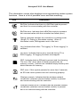

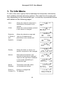
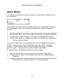
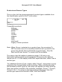

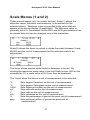


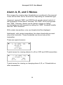

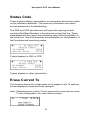
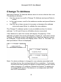
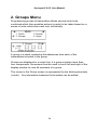


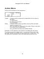


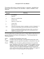


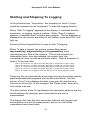


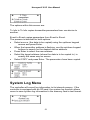
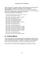


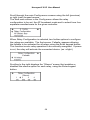
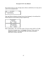


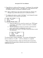


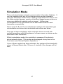

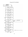


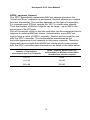

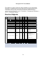
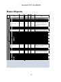
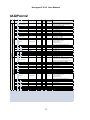


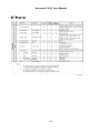


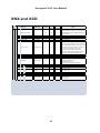


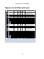


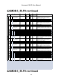


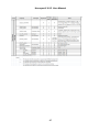


![121290 CR-4000 Controller User Manual [English].pub](http://vs1.manualzilla.com/store/data/005770288_1-ff1b31ed544f6d88740c7f5db9da46b2-150x150.png)