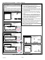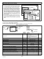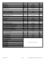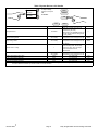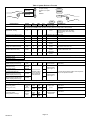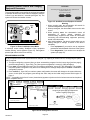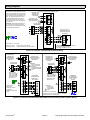
1
INSTALLER'S SYSTEM SETUP GUIDE ®2014 Lennox Industries Inc. Dallas, Texas, USA iComfort Wi-Fi® Thermostat Touch Screen Programmable Communicating Thermostat iComfort Wi-Fi® Web and Mobile Apps CONTROLS 507343-01 10/2014 Supersedes 7/2014 Litho U.S.A. Overview — Technical Description and Features This 24VAC thermostat is an electronic communicating, color display touchscreen and 7-day programmable thermostat. This thermostat stores system parameters and settings in non-volatile memory (i.e., retains data when electrical power fails or is turned off). iComfort Wi-Fi® Thermostat NOTICE Read this manual before programming this thermostat. Use this thermostat only as described in this manual. iComfort® Units Indoor Unit The thermostat also supports: Outdoor Units G71MPP-03 or later SLP98-01 or later SL280-03 or later EL296V-01 or later CBX40UHV-02 or later CBX32MV-06 or later This thermostat can also connect to online services via the Internet through the homeowner's Wi-Fi router. After online registration is completed, the system may then be accessed by the homeowner from anywhere using a remote Internet connection via computer or personal communicating device. XC17-02 or later XP17-02 or later XP17N-01 or later XP19-06 or later XC21-05 or later XP21-01 or later XP21N-01 or later XP25-01 or later XC25-01 or later Shipping and Packing List 1 - iComfort Wi-Fi® thermostat (firmware version 2.13) 4 - Mounting screws 4 - Wall anchors 1 - Installation quick‐start guide 1 - Installer's system setup guide 1 - Homeowner's manual 1 - Warranty card WARNING Improper installation, adjustment, alteration, service or maintenance can cause property damage, personal injury or loss of life. Installation and service must be performed by a licensed professional HVAC installer (or equivalent) or service agency. Wireless bands 802.11b, 802.11c and 802.11n, Three languages are supported (English, Français and Español), Air conditioning or heat pump units with up to four stages of heat / two stages of compressor operation (2 stages of heat pump heating, 2 stages of auxiliary back-up heating, 2 stages of emergency heating), Variable - capacity / multiple - stage heat/cool, universal compatibility (gas/electric/heat pump/air conditioner) Dual-fuel capable (iComfort® heat pump only) with two balance points. Indoor air quality with time‐based notification of consumables including media filters, UVC bulbs, humidifier pads, and PureAir system catalyst service / replacement, iHarmony® zoning system (2 - 4 zones), Lennox iComfort® Equipment Interface Module (Catalog number 10T50) (provides iComfort Wi-FI® to non-communicating indoor unit, Humidification measurement and control, Dew point adjustment control, Humiditrol® Enhanced Dehumidification Accessory (EDA), Equipment maintenance reminders, Autochangeover mode -- Permits control of heating, cooling, humidification, and dehumidification without user involvement, All Lennox branded iComfort® outdoor units have a outdoor temperature sensor factory installed, Enhance defrost control options for Lennox communicating heat pumps using Intellifrost Adaptive Defrost Control, part number 103369-04 or later. TABLE OF CONTENTS Overview — Technical Description and Features . . . 1 Gas Heat Control . . . . . . . . . . . . . . . . . . . . . . . . . . . . . . 38 Installation and Setup . . . . . . . . . . . . . . . . . . . . . . . . . 3 Alerts and Troubleshooting . . . . . . . . . . . . . . . . . . . . . 40 Adjusting System Settings . . . . . . . . . . . . . . . . . . . . . . 3 Wiring Diagrams . . . . . . . . . . . . . . . . . . . . . . . . . . . . . . 53 Identifying System Devices . . . . . . . . . . . . . . . . . . . . . 5 Configuring Air Handler Electric Heat . . . . . . . . . . . . . 56 Non-Communicating Equipment - Adding Outdoor Unit, Dehumidifier and Humidifier . . . . . . . . 5 Typical Systems Setup . . . . . . . . . . . . . . . . . . . . . . . . . 57 Adjusting Equipment Parameters . . . . . . . . . . . . . . . . 8 Complete iComfort ® System - Adjusting Humidification Settings . . . . . . . . . . . . . . . . . . . . . . . . . 14 iComfort ® System Complete - Adjusting Dehumidification Settings . . . . . . . . . . . . . . . . . . . . . . . 16 Partial iComfort ® System - Adjusting Humidification Settings (Non-Communicating Outdoor Unit) . . . . . . 18 Partial iComfort ® System - Adjusting Dehumidification Settings (Non-Communicating Outdoor Unit) . . . . . . 19 Auxiliary Dehumidification (Communicating and Non-Communicating Outdoor Units . . . . . . . . . . . . . . 20 Adjusting Zoning Control Settings . . . . . . . . . . . . . . . . 21 Using the Tests / Diagnostics Features . . . . . . . . . . . 23 Connecting to a Home Wi-Fi Router . . . . . . . . . . . . . 24 Troubleshooting Wi-Fi Connection . . . . . . . . . . . . . . . 25 Registering the Thermostat . . . . . . . . . . . . . . . . . . . . . 26 Account Registration for Server . . . . . . . . . . . . . . . . . 27 Using the Secure Web Portal ........................ 27 .................................................. 27 Skins Screen-Saver ......................................... 27 Accessing Installer Screens and Changing Equipment Parameters . . . . . . . . . . . . . . . . . . . . . . . . . 28 Stage Delay and Differential Settings (Installer Settings) . . . . . . . . . . . . . . . . . . . . . . . . . . . . . 29 Smooth Setback Recover . . . . . . . . . . . . . . . . . . . . . . 30 Max Defrost . . . . . . . . . . . . . . . . . . . . . . . . . . . . . . . . . . 31 Heat Pump, Dual-Fuel, Duel-Fuel Tempering and Balance Points . . . . . . . . . . . . . . . . . . . . . . . . . . . . . . . 35 Modulating Outdoor Unit with Duel-Fuel . . . . . . . . . . 37 507343-01 iComfort ® Furnace and Air Conditioner . . . . . . . . . . . iComfort ® Furnace and Heat Pump (Dual-Fuel) . . . . iComfort ® Air Handler and Air Conditioner . . . . . . . . iComfort ® Air Handler and Heat Pump . . . . . . . . . . . iComfort ® Furnace and non-communicating Air Conditioner . . . . . . . . . . . . . . . . . . . . . . . . . . . . . . . . iComfort ® Furnace and Non-communicating Heat Pump (Dual-Fuel) . . . . . . . . . . . . . . . . . . . . . . . . iComfort ® Air Handler and Non-communicating Air Conditioner . . . . . . . . . . . . . . . . . . . . . . . . . . . . . . . . . . . iComfort ® Air Handler and Non-communicating Heat Pump . . . . . . . . . . . . . . . . . . . . . . . . . . . . . . . . . . . iComfort ® Equipment Interface Module . . . . . . . . . . . Replacement iComfort® Controls . . . . . . . . . . . . . . . . 57 58 59 60 61 61 62 63 64 65 CAUTION This is a 24VAC Class 2 thermostat. Do not install on voltages higher than 30VAC. Do not switch system to cool if the outdoor temperature is below 45°F (7°C). This can damage the cooling system. CAUTION Electric shock hazard. Always turn off power at the main power source by switching the circuit breaker to the OFF position before installing or re moving this thermostat. All wiring must conform to local and national building and electrical codes and ordinances. IMPORTANT ! Connections to non-communicating outdoor units and accessories are described in the Quick-Start Installation guide. Wiring diagrams are also provided beginning on page 53 of this manual. Page 2 Figure 3. View/Edit Time and Date Installation and Setup When Time and Date screen appears, enter the correct date During initial thermostat start-up the following screen will as follows: appear (see figure 1). This indicates that the thermostat is active and booting up. Use the left and right arrows to change the month and year. ... Touch a day of the month to select it. Press on the hour or minute; up down arrows appear to allow change. Touch the am/pm field to toggle it between am and pm. When the correct date and time is set, press save to save Figure 1. Boot-Up Screen settings and return to previous settings screen. COMMUNICATION ERROR SCREEN During initial thermostat start-up if the following screen Touch next to continue to next screen. appears (see figure 2), this will indicate that the thermostat has been incorrectly wired or has shorted wires. Turn power off to the system and verify that all wiring is correct. system settings January 2012 S 1 Figure 2. Communication Error Screen M 2 T W 3 4 11 T F 5 12 S 6 7 8 9 10 13 14 15 16 17 18 19 20 21 22 23 24 25 26 27 28 29 30 31 09 : 39 am save 9:39 am Aug 15, 2012 Adjusting System Setting Figure 4. Set Current Time and Date SET TIME AND DATE Use the arrows to select Time and Date; press edit to CIRCULATE FAN ON TIME SETTING proceed to the Set current time and date screen. NOTE - If the circulate fan mode is on, a timer is set to measure all the time that the fan is blowing, regardless if it is system settings To adjust a setting, highlight it, running to deliver heating or cooling or just for circulation. Time and Date Daylight Saving Time Circulate Fan ON Time System Name Dealer Number Dealer Name Dealer Address Dealer Phone Dealer Email then press edit Circulate is enabled on the user's home screen or system settings page. It keeps air circulating from 15% to 50% percent of time. The following settings approximate how long the fan will run at these typical settings: current value: 9:39 am Aug 15, 2012 edit back 15% (9 minutes fan run time per hour) 25% (15 minutes fan run time per hour) 35% (21 minutes fan run time per hour) 45% (27 minutes fan run time per hour). next 9:39 am Aug 15, 2012 iComfort Wi-Fi® Page 3 7-Day Programmable Communicating Thermostat DEALER NUMBER Either the dealer number or phone number is required. Once either number is entered, all other fields will automatically be populated once the thermostat has been registered during the Wi-FI setup procedure later on in this instruction (if the dealer has an account with Lennox already). NOTE - Dealer number is the dealer's Lennox account number. Dealer phone number is the dealer's main office phone number. 1. Use the arrows to scroll down to the Dealer Number or Dealer Phone setting. Press the edit button. 2. Enter the Dealer Number or Dealer Phone Number using the on-screen keyboard (see figure 5). Press save to continue. NOTE: If a Dealer Number or Dealer Phone Number is not entered and the next button is selected, a pop-up warning screen will appear. 3. Press yes to continue to the System Devices screen. Press no to return to the system settings screen. system settings To adjust a setting, highlight it, then press edit Time and Date Daylight Saving Time Circulate Fan ON Time Temperature Unit System Name Dealer Number Dealer Name Dealer Address Dealer Phone current value: edit back next 9:39 am Aug 15, 2012 WARNING Please enter your DEALER PHONE NUMBER or DEALER NUMBER If you do not enter either, the thermostat will not show up on DaveNet and you will not be able to remotely monitor the system status or receive email alerts when there is a problem. The dealer number is your Lennox account number) i.e A12345). Your dealer phone number should be the main office phone number associated with your dealership. If you have any questions, please contact your Lennox representative. Are you sure you want to proceed? yes no Figure 5. Dealer Number Selection and Warning Table 1. System Settings system settings Time and Date Daylight Saving Time Circulate Fan ON Time Temperature Unit System Name Dealer Number Dealer Name Dealer Address Dealer Phone Parameter Name: To adjust a setting, highlight it, then press edit current value: 9:39 am Aug 15, 2012 edit back next Default Parameter Value Setting Increment — (Time/date elements screen) — Daylight Saving Time Enabled Enabled, Disabled — Circulate Fan ON time 35% Range 15 to 45% 1% Fahrenheit Fahrenheit or Celsius — — (keyboard input screen) — Time and Date Temperature Unit System Name Dealer Number Dealer Name Dealer Address **** — Lennox — — (keyboard input screen) Note: When adding the dealer number, all other dealer fields will auto populate once thermostat registration is completed. — Dealer Phone 1-800-9-LENNOX Dealer Email — — www.lennox.com — Dealer Website 507343-01 Page 4 — Identifying System Devices From the “system devices” screen, use arrow buttons to scroll to a device; then press the about button. Use the up/down arrows to scroll through and view additional information about the selected device. When finished viewing, press the back button. system devices press 'about' for more information on a highlighted device System Heat Pump Furnace Thermostat about back 9:39 am Aug 15, 2012 device feature list Language Support Equipment Type Name Unit Model Number Unit Serial Number Unit Nominal Capacity Number of Heating Stages Heating Capacity by Stage Indoor Blower CFM Range Control Software Revision Control Model Number next device description Furnace Equipment Type Name Furnace (returns to system devices screen) back Non-Communicating Equipment — Adding Outdoor Unit, Dehumidifier and Humidifier NON-COMMUNICATING EQUIPMENT — ADDING OUTDOOR UNIT Add or Remove Non-communicating equipment? System Devices System 1 To add (or remove) an outdoor unit that is not iComfort® you must be at the “Add or Remove Non-communicating equip ment?” screen. 1. Press the yes button on this screen (see 1). 2. In the non-communicating device list screen, use the arrows (2a) to highlight Outdoor Unit Type and press edit (2b). 3. Touch one of the radio buttons (3a) to select a 1-or 2-Stage AC Unit or a 1-or 2-Stage HP Unit; press save (3b). 4. Use arrows (4a) to highlight any red colored text in the device list (e.g. select Outdoor Unit Capacity; text turns white). Press edit (4b). 5. Use arrows (5a) to make changes; press save (5b). Change other red settings (if present) using a similar process. NOTE - If the defaults are correct, you do not have to make any changes, but you must press save (5b). When all red text is gone, the back button will appear; press it to return to the Add or Remove Non-communicating equipment screen (1). yes Furnace to add/remove/adjust a device, select it, then press edit non-communicating device list Outdoor Unit Type current value: Humidifier Dehumidifier Not Installed 2a back 2b next edit Outdoor Unit Type Select one Not Installed 1 Stage A/C Unit 2 Stage A/C Unit 2 Stage HP Unit 1 Stage HP Unit 3a non-communicating device list back Outdoor Unit Type Outdoor Unit Capacity Humidifier Dehumidifier save to add/remove/adjust a device, select it, then press edit current value: 2 Stage AC Unit 4a please view and save all red settings cancel edit Outdoor Unit Capacity Range is 18 to 60 Default is 60 kBTU inc: 1 4b 3b set-to 60 kBTU 5a back 5b 9:39 am Aug 15, 2012 save cancel Figure 6. Add Non-Communicating Device — Outdoor Unit iComfort Wi-Fi® Page 5 7-Day Programmable Communicating Thermostat NON-COMMUNICATING EQUIPMENT — ADDING A HUMIDIFIER Before adding a humidifier, be sure that: The humidifier is wired to the furnace or air handler control as shown on the optional accessories wiring diagram. The entire system is wired, powered up, and the thermostat has detected the system's installed com municating devices, and you are at the Add or Re move Non-communicating equipment? screen. system devices Add or Remove Noncommunicating equipment? System Heat Pump Furnace 1 yes Thermostat back to add/remove/adjust a device, select it, then press edit non-communicating device list Humidifier current value: Dehumidifier Electronic Air Cleaner 2a 3b Not Installed Humidifier Select one 3a Not Installed save 2b Options available for EL296 and SL280 cancel to add/remove/adjust a device, select it, then press edit Humidifier current value: Dehumidifier Electronic Air Cleaner 2a Not Installed 3a Power (120VAC Humidifier to add/remove/adjust a device, select it, then press edit non-communicating device list Humidifier Not Installed edit Humidification non-communicating device list Select one next To add (or remove) a humidifier: 1. Press the yes button on this screen (see 1). 2. In the “non-communicating device list” screen, use the arrows (2a) to highlight Humidifier (note the current value, Not Installed) and press edit (2b). 3. Touch one of the radio buttons (3a) to select humidific ation equipment type. Options available are dependent on indoor unit model. 4. The previous screen returns, but the current value now shows your selection (4a). Press the back (4b) button. 5. The Add or Remove... screen reappears with your addition shown in the system devices list (5a). At this point, you may add more equipment (press yes) or if finished, press the next (5b) button to advance to the Adjust a setting... screen (see page 18). NOTE - Adding humidity regulating non-communicating de vices may be a 2-step procedure: 1st, the device must be installed and wired. After the hu midifier is installed, the setting under the System mode Humidification Control Mode defaults to Basic). 2nd, (if you want another mode, i.e. Precision, Basic Dew Point, or Precision Dew Point, the device requires further configuration (see page 18). 2b edit Humidifier Bypass (24VAC) Humidifier current value: Dehumidifier Electronic Air Cleaner Bypass and Power Humidifier xxxxxxxxxxxxxxxxxxxxxxxr 4a edit 3b save Options available for SLP98 cancel 4b back to add/remove/adjust a device, select it, then press edit non-communicating device list Humidifier Select one Not Installed 3b system devices current value: Dehumidifier Electronic Air Cleaner 2a Not Installed Humidifier 3a save 2b Thermostat Bypass (24VAC) Humidifier 5a Options available for CBX32MV and CBX40UHV 5b back 9:39 am Aug 15, 2012 Figure 7. Add Non-Communicating Device — Humidifier 507343-01 yes Heat Pump Furnace edit Bypass (24VAC Humidifier cancel Add or Remove Noncommunicating equipment? System Page 6 next NON-COMMUNICATING EQUIPMENT — ADDING HUMIDITROL® OR AUXILIARY DEHUMIDIFIER Before adding a dehumidifier, be sure that: the dehumidifier is wired to the furnace or air handler control as shown on the optional accessories wiring diagram. the entire system is wired, powered up, and the ther mostat has detected the system's installed communi cating devices, and you are at the Add or Remove Non-communicating equipment? screen. Add or Remove Non-communicating equipment? system devices System 1 yes Furnace to add/remove/adjust a device, select it, then press edit non-communicating device list Humidifier Dehumidifier Electronic Air Cleaner current value: If 'no', press Next Step 2a Not Installed Select one Not Installed 3a 2b edit Dehumidifier back next Humiditrol Auxiliary Dehumidifier save 3b cancel Outdoor Unit Dehumidifier system devices to add/remove/adjust a device, select it, then press edit non-communicating device list Outdoor Unit Capacity Humidifier To add (or remove) a dehumidifier, you must be at the Add or Remove Non-communicating equipment? screen. 1. Press the yes button on this screen (see 1). 2. In the non-communicating device list screen, use the arrows (2a) to highlight Dehumidifier and press edit (2b). Note the current value (e.g. Not Installed). 3. Touch one of the radio buttons (3a) to select the type of dehumidifier (or select Not Installed, if removing dehumidifier); press save (3b). 4. When you scroll to the Dehumidifier device (4a), (Note the current value, e.g. Humiditrol.) Click back (4b) to return to the Add or Remove... screen (1). 5. The Add or Remove.. screen reappears with your addition shown in the system devices list (5a). At this point, you may add more equipment (press yes) or if finished, press the next button (5b) to advance to the Adjust a setting... screen ). NOTE - Adding humidity regulating non-communicating devices may be a 2-step procedure: 1st, the device must be installed and wired. After the dehumidifier is installed, the setting under the System mode Dehumidification Control Mode defaults to Basic). 2nd, set Humiditrol ® comfort adjust overcooling and the min/max dehumidification setpoints if desired (see page 18). current value: 4a System Add or Remove Noncommunicating equipment? yes Heat Pump Furnace Thermostat Humiditrol Humiditrol 5a edit 5b back 4b back next Figure 8. Add Non-Communicating Device — Dehumidifier iComfort Wi-Fi® Page 7 7-Day Programmable Communicating Thermostat Adjusting System Device Settings 1. Press any component listed under system devices to change specific communicating equipment para meters and edit details of devices in the system. 2. Use the arrows to highlight a setting and then press edit (figure 9A). In the example, the low heating air flow is changed from the default (400) to 325 (figure 9B). After changing, press save. (note the current value has changed; figure 9C). Some changes may affect other settings and, if so, those affected will appear in red and require changing/saving to clear the red settings. 3. When finished, press back; equipment parameters screen then press next. Select tests to run screen appears; either run tests as before or press skip tests. System Low Heating Airflow Equipment Name current value: Heating Airflow Control Type Low Heating Airflow 400 edit High Heating Airflow High Cooling Airflow Airflow Profile - Cooling System High HP Airflow Equipment Name Continuous Indoor Blower Airflow reset All Low Heating Airflow current value: back 325 Heating Airflow Control Type Heating Indoor Blower OFF Delay Low Heating Airflow High Heating Airflow 9:39 am Aug 15, 2012 Low Heating Airflow High Cooling Airflow Range is 325 to 450 CFM Airflow Profile - Cooling Default is 400, inc: 25 High HP Airflow edit Reset All set-to Continuous Indoor Blower Airflow 325 Heating Indoor Blower OFF Delay 9:39 am Aug 15, 2012 CFM save back cancel Figure 9. Edit Equipment Details iComfort ® UNIT CONFIGURABLE SETTINGS The following tables list the system devices settings available from the installer setup screens. Table 2. System Devices > System system devices System Heat Pump Furnace Thermostat To adjust a setting, highlight it, then press Edit about resetAll System edit 9:39 am Aug 15, 2012 back Parameter Name: Equipment Name Filter 1 Timer Selection Filter 2 Timer Selection UV Bulb Timer Selection Humidifier Pad Timer Selection PureAir Timer Selection Smooth Setback Recovery Electric Heat Control Mode EvenHeat Discharge Temp Number of Gas Heating Stages (SLP98V only) (staged selection) Modulating Gas Heating Steady State PI (SLP98V only) Modulating Gas Heat Step Change PI (SLP98V only) Modulating HP Heating Cycles Per Hour (XP25 only) Modulating HP Electric Heating Switching Point (XP25 only) Modulating HP Heating Steady State PI Gain (XP25 only) Modulating HP Heating Step Change PI Gain (XP25 only) Modulating Cooling Steady State PI Gain (XC25 and XP25 only) Modulating Cooling Step Change PI Gain (XC25 and XP25 only) Modulating Cooling Cycles Per Hour (XC25 and XP25 only) 507343-01 Default Parameter Value Setting Press edit to change name (up to 35 charac ters may be used). Increment — Note: Pressing the resetALL button will re set all custom parameter settings back to factory default. Calendar Time, Run Time Calendar Time, Run Time Calendar Time, Run Time Calendar Time, Run Time Calendar Time, Run Time Enabled, Disabled Standard, Evenheat 85ºF to 130ºF Staged, Variable Capacity, Load Tracking Variable Capacity 1, 2, 3 or 4 Less Aggressive, More Aggressive, Standard Less Aggressive, More Aggressive, Standard 3.0 to 6.0 0.0 to 2.0 Less Aggressive, More Aggressive, Standard Less Aggressive, More Aggressive, Standard — Calendar Time Calendar Time Calendar Time Calendar Time Calendar Time Enabled Standard 85ºF Gas Heat Control Mode Staged 4 Standard Standard 4.0 1.0 Standard Standard Less Aggressive Less Aggressive 4.0 Page 8 next — — — — — — — 15ºF — — — — 0.5 0.25 — — Less Aggressive, More Aggressive, Standard — Less Aggressive, More Aggressive, Standard — 3.0 to 6.0 0.5 Parameter Name: Auto Changeover - Temp Dead-band Max Heat Set point Min Cool Set point Heat Cool Stages Lock In Balance Point Control Default 5ºF 90ºF 60ºF 60ºF Disabled Maximum Overcooling Humiditrol Comfort Adjust Increment 1ºF 1ºF 1ºF 1ºF — 45ºF 5ºF 0ºF 15 minutes Parameter Value Setting 3 to 9ºF 40 to 90ºF 60 to 99ºF 60 to 99ºF Disabled or Enabled Maximum, Minimum and Midpoint Overcooling Display Only, Precision, Precision Dew Point Control, Basic, Basic Dew Point Control 15 to 45ºF 5 to 10ºF -15ºF to 15ºF 5 to 30 minutes 120 minutes 60 to 240 minutes 30 minutes Disabled 1.0ºF 1.0ºF 1.0ºF Enabled 20 Minutes 20 Minutes Enabled, Disabled 0.5 to 3ºF 0.5 to 8ºF 0.5 to 8ºF Enabled, Disabled 5 to 120 Minutes 5 to 120 Minutes — 0.5ºF 0.5ºF 0.5ºF — 5 Min 5 Min 2 0 to 5 1 40 0ºF 100ºF 60 Seconds 50ºF 100ºF 90ºF 40ºF 140ºF 50 to 55 RH% -10 to 10ºF 80 to 110ºF 0 to 120 seconds 50 to 60ºF 100 to 130ºF 85 to 110ºF 35 to 45ºF 140 to 160ºF 1 1ºF 1ºF 5 seconds 1ºF 5ºF 1ºF 2ºF 5ºF Humidification Control Mode Basic Max Humidification Setpoint Auto Changeover - Humidif. Dead-band Dew Point Adjustment Humiditrol and Aux Dehum Min Run Time HP Heating Lockout Time (enabled in zoning system) - When heat pump cannot satisfy demand in a reason time, the control switches to gas heating and lockout the heat pump for 120 minutes by default. Heat Cool Stages Locked In *1st Stage Differential *2nd Stage Differential *3nd Stage Differential Stage Delay Timers *2nd Stage Delay *3rd Stage Delay Electric Heat Stage During Defrost (Used to adjust the number of electric heat ing elements that will be energized when the heat pump is in defrost mode.) Min De-humidification Setpoint Outdoor Temperature Reading Calibration Zoning Gas heating DAT Cool down Target Zoning Anticipated Discharge Air Temperature Adjustment Zoning Target Supply Air Temp for Cooling Zoning Target Supply Air Temp for Gas/Electric Heating Zoning Target Supply Air Temp for HP Heating Zoning Supply Air Temp Limit for Cooling Zoning Supply Air Temp Limit for Gas/Electric Heating — — 1ºF 1ºF 1ºF 5 minutes *Number of stages shown in thermostat is dependent on equipment that is installed. Electric heat will bring on 2 elements at a time if available. Off Off, 40ºF (4ºC), 45ºF (7ºC), 50ºF (10ºC), 55ºF (13ºC) HP Heating Lockout Time 120 Minutes Range is 60 to 240 minutes. 60 Min Zoning Minimum Zone Run Time Zone 1 First Stage Differential Zone 2 First Stage Differential Zone 3 First Stage Differential Zone 4 First Stage Differential Zone 1 Continuous Blower CFM Zone 2 Continuous Blower CFM Zone 3 Continuous Blower CFM Zone 4 Continuous Blower CFM Zone 1 Cooling CFM Zone 2 Cooling CFM Zone 3 Cooling CFM Zone 4 Cooling CFM Zone 1 Heating CFM Zone 2 Heating CFM Zone 3 Heating CFM Zone 4 Heating CFM 120 Seconds 1.0ºF 1.0ºF 1.0ºF 1.0ºF Range is 90 to 600 seconds 0.5 to 3.0ºF 0.5 to 3.0ºF 0.5 to 3.0ºF 0.5 to 3.0ºF 30 Sec 0.5ºF 0.5ºF 0.5ºF 0.5ºF Lock in 2nd stage HP by Outdoor Temp iComfort Wi-Fi® — To be determine by equipment capacity. Page 9 7-Day Programmable Communicating Thermostat Table 3. System Devices > Air Conditioner system devices System Air Conditioner Furnace Thermostat To adjust a setting, highlight it, then press Edit about resetAll Air Conditioner edit back Parameter Name: Default Equipment Name Outdoor Unit Compressor Short Cycle Delay next Parameter Value Setting Press edit to change name (up to 35 characters may be used). Note: Pressing the resetALL button will reset all custom parameter settings back to factory default. Increment — 300 Seconds 60 to 300 Seconds 60 Sec High Normal Cooling Airflow (XC25 only) 1600 450 to 2150 25 Low Normal Cooling Airflow (XC25 only) 750 450 to 2150 25 0 0 to 30 1 Dehum Airflow Adjustment Adder Table 4. System Devices > Heat Pump system devices System Heat Pump Furnace Thermostat To adjust a setting, high light it, then press Edit about resetAll Heat Pump edit back Parameter Name: Default next Parameter Value Setting Increment Press edit to change name (up to 35 characters may be used). Equipment Name Outdoor Unit Pressing the resetALL button will reset all custom parameter settings back to factory default. — Compressor Short Cycle Delay 300 Seconds Note: The resetALL function is required when replacing the outdoor unit control with a new control part number 103369-04). Performing the resetALL task will enable new defrost parameters to be accessible. 60 to 300 Seconds Compressor Shift Delay On/Off On On, Off High Normal Cooling Airflow (XP25 only) 1600 450 to 2150 25 Low Normal Cooling Airflow (XP25 only) 750 450 to 2150 25 High Normal HP Heating Airflow (XP25 only) 1600 450 to 2150 25 Low Normal HP Heating Airflow (XP25 only) 750 450 to 2150 25 0 0 to 30 1 50ºF to 100ºF 10ºF Dehum Airflow Adjustment Adder 60 Sec Defrost Termination Temp 50ºF When Outdoor Control 103369-04 or later is used, the follow ing options are available: 50F (10C), 90F (32C), 70F (21C) and Max Defrost — Automatic Max Defrost (parameter only available if using outdoor control 103369-04 or later). See page 31 for further details. OFF OFF or ON 1 Max Defrost by Weather (parameter only available if using outdoor control 103369-04 or later). See page 31 for further details. OFF OFF or ON 1 507343-01 Page 10 Table 5. System Devices > Air Handler system devices System Heat Pump Air Handler Thermostat To adjust a setting, highlight it, then press Edit about resetAll Air Handler edit next back Parameter Name: Default Parameter Value Setting Increment Press edit to change name (up to 35 characters may be used). Equipment Name Air Handler Note: Pressing the resetALL button will reset all custom parameter settings back to factory default. — Electric Heating Airflow nnnn CFM (See Note at end of table) NOTE: CFM Default and Values Settings are dependent on the tonnage of the unit 5CFM High Cooling Airflow nnnn CFM (See Note at end of table) NOTE: CFM Default and Values Settings are dependent on the tonnage of the unit 5CFM 1: No Delays, Airflow Profile - Cooling 1 2: ON: No delays; OFF: 45 sec delay 3: ON: 82%/7.5min; OFF: No delays — 4: ON: 50%/30s,82%/7.5min; OFF:50%/30s nnnn CFM (See Note at NOTE: CFM Default and Values Settings 10CFM end of table) are dependent on the tonnage of the unit Heating Indoor Blower OFF Delay 10 sec 0 to 10 Seconds 1 sec Heating Indoor Blower ON Delay 0 sec 0 to 5 Seconds 1 sec Cooling Indoor Blower OFF Delay 0 sec 0 to 30 Seconds 2 sec Cooling Indoor Blower ON Delay 2 sec 0 to 10 Seconds 1 sec Note All communicating Installer Parameters default CFM values based on DIP switch setting (non-communicating value) are calculated using the CFM conversion tables and rounded up to closest number on 25 CFM resolution. Continuous Indoor Blower Airflow iComfort Wi-Fi® Page 11 7-Day Programmable Communicating Thermostat Table 6. System Devices > Furnace system devices To adjust a setting, highlight it, then press Edit System Heat Pump Furnace Thermostat about resetAll Furnace edit back Parameter Name Equipment Name Airflow Profile - Cooling Default Min. Max. Incr. Dependency next Note or Options Press edit to change name (up to 35 characters may be used). Note: Pressing the resetALL button will reset all custom parameter settings back to factory default. - 1- - 70 60 8- 1 None Heating Indoor blower OFF delay DIP SW 60 180 10 None DIP switch setting in Non-comm. Heating Indoor blower ON delay 30 sec 15 45 5 None 45 sec fixed in Non-Comm. IFC Not used on Non Comm. IFC Continuous Indoor Blower Airflow De-humidification Airflow % None A:ON:50%/30S,82%/7.5min OFF:5-%/30S B:ON:82%/7.5min; OFF: No delays C:ON: No delays; OFF: 45sec delay D:No delays A nnnn CFM (See Note 3 at end of table) Cooling Indoor blower OFF delay 0 sec 0 30 2 Outdoor Unit present Cooling indoor Blower ON Delay 2 sec 0 10 1 Outdoor Unit present 2 sec fixed in Non-Comm. IFC HP Indoor Blower OFF Delay 45 sec 0 60 5 Heat Pump present Not used on Non Comm. IFC HP Indoor Blower ON Delay 0 sec 0 30 5 Heat Pump present Not used on Non Comm. IFC Heating Airflow Control Type Selections available if discharge air temperature sensor is installed (fixed cfm and fixed discharge air temperature). Low Heating Airflow Low and high heating air flow is dependent on model of indoor unit High Heating Airflow Gas Heat Airflow Settings Heating Airflow Control Type (variable capacity furnaces only) 0 – Fixed CFM Low Heating Airflow (CFM @ min. heat) DIP SW High Heating Airflow (CFM @ 100% heat) DIP SW Low Heating Discharge Air Temperature (DAT @ min heat) (variable capacity furnaces only) DIP SW* High Heating Discharge Air Temperature (DAT @ 100% heat) (variable capacity furnaces only) DIP SW* 0 1 1 25 See furnace docu mentation (IOM or Product Specifica tions) for size spe cific information 25 DATS installed 0 (Fixed CFM) 1 (Fixed DAT) Heating Airflow Control Type = 0 See furnace documentation (IOM or Product Specifica tions) for size specific information 5 Heating Airflow Control Type = 1 5 * - Default DAT value is rounded to the closest number on 5 deg F resolution and limited by Minimum and Maximum value. Cooling Airflow Settings High Cooling Airflow (CFM @ 100% cool) Outdoor unit tons 400CFM Low Cooling Airflow (CFM @ lowest cool stage) (See Note 1 at end of table) 507343-01 Min CFM Max CFM 25 Min CFM Max CFM 25 Min CFM Max CFM 25 Min CFM Max CFM 25 Outdoor Unit present 2+ stage Outdoor Unit present Page 12 1/2 HP blower 1 HP blower 1/2 HP blower 1 HP blower Heat Pump Airflow Settings High Heat Pump Airflow (CFM @ 100%) Outdoor unit tons 400CFM Low Heat Pump Airflow (CFM @ lowest stage) (See Note 2 at end of table) Min CFM Max CFM 25 Min CFM Max CFM 25 Min CFM Max CFM 25 Min CFM Max CFM 25 Min CFM Max CFM 25 Min CFM Max CFM 25 Min CFM Max CFM 25 Min CFM Max CFM 25 1/2 HP blower Heat Pump present 1 HP blower 1/2 HP blower 2+ stage Heat Pump present 1 HP blower Other Parameters Continuous Indoor Blower Airflow Same as above Humidification Airflow Note 1: Note 2: Note 3: DIP SW (See Note at end of table) 1/2 HP blower None 1 HP blower 1/2 HP blower Humidifier present 1 HP blower Minimum Outdoor Unit Cooling Stage as a percentage of High Cooling Airflow (value is rounded up to the closest number on 25 CFM resolution. Minimum Outdoor Unit Heating Stage as a percentage of High Heat Pump Airflow (value is rounded up to the closest number on 25 CFM resolution). All communicating Installer Parameters default CFM values based on DIP switch setting (non-communicating value) are calculated using the CFM conversion tables and rounded up to closest number on 25 CFM resolution. Table 7. System Devices > Thermostat system devices System Heat Pump Furnace Thermostat To adjust a setting, high light it, then press Edit about resetAll Thermostat edit back next Press edit to change name (up to 35 characters may be used). Equipment Name — Temp Reading Calibration 0ºF -5ºF to 5ºF 1ºF Humidity Reading Calibration 0% -10 to 10% 1%RH Note: Pressing the resetALL button will reset all custom parameter settings back to factory default. — Table 8. System Devices > Zoning Control system devices System Heat Pump Furnace Thermostat Zoning Control To adjust a setting, high light it, then press Edit about resetAll Zoning Control edit back Parameter Name next Default Min. Max. Incr. Zone 2 Temp Reading Calibration 0ºF -5ºF 5ºF 1ºF Zone 3 Temp Reading Calibration 0ºF -5ºF 5ºF 1ºF Zone 4 Temp Reading Calibration 0ºF -5ºF 5ºF 1ºF Dependency Damper control module installed NOTE - More zoning parameters are available under system devices > system on page 9. iComfort Wi-Fi® Page 13 7-Day Programmable Communicating Thermostat Complete iComfort® System — Adjusting Humidification Settings SYSTEM DEVICES SCREEN — HUMIDIFICATION CONTROL MODE SETTINGS To adjust a setting, highlight it, then press Edit System Devices System System Air Conditioner Furnace about 1a Thermostat Power (120VAC) Humidifier 1b System Humidification Control Mode resetAll 2nd Stage Differential Staged Delay Timers current value: back 2nd Stage Delay Min Dehumidification Setpoint Humidification Control Mode Select one 2a next edit Basic 2b Humidification Control Mode Display Only Precision edit reset Basic 3a Basic Dew Point Control back Precision Dew Point save 3b cancel Pre-adjustment REQUIREMENTS: 1st, the device has been installed (see page 6). 2nd, you pressed next at the “Add or Remove...” screen (see page 6). Configure the device as follows: 1. In the “system devices” list, use the arrows (1a) to high light System. Press edit (1b). 2. In the “System” list, use the arrows (2a) to highlight Hu midification Control Mode. The current value defaults to Basic mode. Press edit (2b). 3. Touch one of the radio buttons (3a) to select the mode of humidification control; press save (3b). (After saving, check that the current value now shows the new selec tion). 4. Press the back button to return to “Adjust a setting...” screen. NOTE - If the defaults for the settings shown in red, you are not required to make any changes, but you must go into the edit tool, and press save (5b). When all red text is gone, the back button will appear; press it to return to the “Adjust a setting...” screen. Basic Dew Point Control adjustment mode will change the humidi fication set point based: on the outdoor temperature user-defined Dew Point Adjustment setting user-defined Auto Changeover - Humidif. Deadband setting user-defined Max Humidification Setpoint setting Precision Dew Point Control adjustment mode will operate when these conditions are met: humidification mode has been enabled humidification demand exists (24V present at H). the unit is in HEAT mode user-defined Dew Point Adjustment setting user-defined Auto Changeover - Humidif. Deadband setting user-defined Max Humidification Setpoint setting NOTE - In dew point adjustment mode, the humidification setpoint has no effect whatsoev er on unit operation. Only the user-defined dew point adjustment setting affects operation per the following formula: Outdoor Temp (ºF) RHuser dew point + 25 + adjustment 2 RH Where: user dew point adjustment cannot exceed +/- 15% and RHsetpoint minimum is 15% and cannot exceed 45% RHsetpoint = Figure 10. Complete iComfort® System Devices Screen — Humidification Setting 507343-01 Page 14 FEATURE SCREEN — HUMIDIFICATION SETTINGS 1. From the Main Screen, press the right arrow icon to go the the Features screen. 2. From the Features screen, select system settings. 3. Touch the button of the humidification controls you want to adjust; if it says humidifier OFF, one touch will display a selection for ON. 4. When you touch the set-to button, the arrows ap pear, allowing you to change to the desired humidity percentage setting. How Humidification Mode Works SYSTEM SETTINGS Appears only when heat pump is present heating mode COMFORT humidifier controls humidifier is ON (default is ON) % 35 set to de-humidifier controls ClimateIQ setting MOD % 40 set to (default is DRY) humidifier display is ON (default is ON) Select the humidity level that matches your regional weather Wi-Fi 9:39 am Aug 15, 2012 ? DISPLAY, BASIC AND PRECISION—These modes allow user control of relative humidity between 15 and 45%. These conditions must be met for either mode to operate: humidification mode has been enabled, and the unit is in HEAT mode, and humidification demand exists (24V present at H), and DISPLAY mode indicates humidification is OFF. BASIC mode mode also requires presence of heating demand [Y for HP heat, or W for gas heat (W may be energized with G de-energized)]. PRECISION—(Available only if Wi-Fi is operational or outdoor sensor is attached) Basic Dew Point Control adjustment mode will change the humidi fication set point based: on the outdoor temperature user-defined Dew Point Adjustment setting Precision Dew Point Control adjustment mode will operate when these conditions are met: humidification mode has been enabled humidification demand exists (24V present at H). the unit is in HEAT mode Figure 11. Complete iComfort® Feature Settings Screen — Humidification Setting iComfort Wi-Fi® Page 15 7-Day Programmable Communicating Thermostat Complete iComfort® System — Adjusting Dehumidification Settings SYSTEM DEVICES SCREEN — DEHUMIDIFICATION SETTINGS Pre-adjustment REQUIREMENTS: 1. In the “system devices” list, use the arrows (1a) to 1st, the device has been installed highlight System. Press edit (1b). 2nd, from the “Add or Remove Non-communicating 2. Humiditrol ® only—In the “System” list, use the ar equipment?”, press next. rows (2a) to highlight Humiditrol Comfort Adjust. 3rd, in the “Adjust a setting...” screen, configure the The current value defaults to Maximum Overcooling. device as follows: Press edit (2b). To adjust a setting, system devices 3. Humiditrol ® only—Touch one of the radio buttons highlight it, System about (3a) to select the overcooling level; press save (3b). then press Edit Air Conditioner (After saving, check that the current value now shows System Furnace resetAll the new selection). Thermostat 1a 1b Humiditrol edit 4. Use arrows (4a) to highlight Min De-humidification System Setpoint; press edit (4b). Note the current value De-humidification Control Mode reinstall 3rd Stage Delay (e.g. 45). 4th Stage Delay current value: 5. Use arrows (5a) to make changes; press save (5b). Lock In 2nd Stage HP by Outdoor Temp Midpoint Overcooling (After saving, check that the current value now shows Balance Point Control reset 2a Humiditrol Comfort Adjust the new selection). Min De-humidification Setpoint edit 2b 6. Press the back button to return to “Adjust a setting...” Humiditrol Comfort Adjust screen. Select one Maximum Overcooling Midpoint Overcooling back Minimum Overcooling 3a save De-humidification Control Mode System 3b Humiditrol Comfort Adjust settings are only available on units equipped with a Humiditrol® De-humidification device. Staged Delay TImers cancel2nd Stage Delay current value: 4th Stage Delay Lock In 2nd Stage HP by Outdoor Temp Min De-humidification Setpoint Range is 40 to 60 Default is 45, inc:1 set-to 45 3rd Stage Delay 4a 4b edit Balance Point Control Humiditrol Comfort Adjust reset Min De-humidification Setpoint OD/Humid Boundary 6 Outdoor Temperature Reading Calibr back 9:39 am Aug 15, 2012 5a 42 % (returns to adjust a setting screen) 5b save cancel Figure 12. Complete iComfort® System Devices — Dehumidification Settings FEATURE SCREEN — DEHUMIDIFICATION SETTINGS 1. From the Main Screen, press the right arrow icon to go the the Features screen. 2. From the Features screen, select system settings. 3. Touch the ClimateIQ setting button. Available options when selected are selection for DRY, MODERATE and HUMID. 4. Selecting HUMID bring on the set-to button. When you touch the set-to button, the arrows appear, allowing you to change to the desired dehumidifier percentage setting COOLING MODE — CLIMATE IQ™ Three climate settings are available: SYSTEM SETTINGS Appears only when heat pump is present heating mode COMFORT humidification settings humidifier is ON (default is ON) % 35 set to De-humidification settings ClimateIQ setting MOD % 40 set to (default is DRY) humidifier display is ON (default is ON) Select the humidity level that matches your environment Wi-Fi 9:39 am Aug 15, 2012 ? HEATING MODE (XP25 ONLY) — CLIMATE IQ™ This technology optimizes dehumidification settings for specific climates to improve home comfort during cooling or heating operations. Dry The system supplies higher indoor airflow at all com pressor capacities, increasing efficiency by operating at a higher sensible-to-total ratio. Two climate settings are available: Moderate The system supplies indoor airflow that balances Comfort The system reduces indoor airflow, in efficiency and comfort. creasing supply air temperature. Humid - The system supplies lower indoor airflow at all com Normal Standard system operation. pressor capacities, improving humidity removal by operating at a lower sensible to total ratio. Figure 13. Dehumidification iComfort® System Controls 507343-01 Page 16 DEHUMIDIFICATION — HOW IT WORKS This is applicable only to the XC17, XP17, XP17N, XC21, XP21 and XP21N models. DRY, MODERATE AND HUMID —These modes allow user control of relative humidity between 40% and 60% RH. These conditions must be met for either Moderate or Humid modes to operate: dehumidification mode has been enabled, and the unit is in COOL mode, and dehumidification demand exists (0V present at H), and DRY mode if off with no dehumidification control. MODERATE mode requires presence of cooling demand (Y for HP heat). HUMID mode requires the system to be in the cooling mode and to of had a cooling call prior to the dehumidification call. Their does not need a cooling call to be present to bring on Humid dehumidification. This mode can over cool the space by 2 degrees while trying to satisfying the dehumidification demand. Humiditrol ® or Auxiliary Dehumidifier mode requires: NOTE - Systems using iComfort® and a dehumidifier - “Dehum” jumper on furnace/air handler control does not need to be cut when using with a iComfort Wi-Fi ® thermostat. dehumidification has been enabled on installer settings, and the unit is in COOL mode, (or if in AUTO and at least one thermostat cooling call made prior to the dehumidification demand), and a dehumidification demand exists (RH above set point), and outdoor temperature is below 95°F and indoor temperature above 65°F (Humiditrol only). iComfort Wi-Fi® MAX adj. - Indoor temp > 2°F above heating set point HEAT setpoint + COOL setpoint MID adj. - Indoor temp > 2 MIN adj. - Indoor temp > 2°F below cooling set point Page 17 7-Day Programmable Communicating Thermostat Partial iComfort® System — Adjusting Humidification Settings (Non-Communicating Outdoor Unit) SYSTEM DEVICES SCREEN — HUMIDIFICATION CONTROL MODE System Devices To adjust a setting, highlight it, then press Edit System System Air Conditioner Furnace about 1a Thermostat Power (120VAC) Humidifier 1b System resetAll Humidification Control Mode 2nd Stage Differential Staged Delay Timers current value: back 2nd Stage Delay De-humidification Control Mo Humidification Control Mode 2a 2b Humidification Control Mode Display Only next Basic edit reset Select one Precision edit Basic 3a Basic Dew Point Control back Precision Dew Point save 3b cancel Pre-adjustment REQUIREMENTS: 1st, the required devices (outdoor unit and humidifier) has been installed (see page 6). 2nd, you pressed next at the Add or Remove... screen (see page 6). Configure the device as follows: 1. In the system devices list, use the arrows (1a) to highlight System. Press edit (1b). 2. In the System list, use the arrows (2a) to highlight Humidification Control Mode. The current value defaults to Basic mode. Press edit (2b). 3. Touch one of the radio buttons (3a) to select the mode of humidification control; press save (3b). (After saving, check that the current value now shows the new selection). 4. Press the back button to return to Adjust a setting... screen. NOTE - If the defaults for the settings shown in red, you are not required to make any changes, but you must go into the edit tool, and press save (5b). When all red text is gone, the back button will appear; press it to return to the Adjust a setting.. screen. Figure 14. Adjust a Non-Communicating Device Setting — Humidification FEATURE SCREEN — HUMIDIFICATION SETTINGS 1. From the main screen, press the right arrow icon to go the the Features screen. 2. From the Features screen, select system settings. 3. Touch the button of the humidification settings you want to adjust; if it says humidifier OFF, one touch will display a selection for ON. 4. When you touch the set-to button, the arrows appear, allowing you to change to the desired humidity per centage setting. SYSTEM SETTINGS De-humidification settings humidification settings humidifier is ON % 40 set to dehumidifier MEDIUM OFF MEDIUM HIGH % 50 set to humidifier display is ON (default is ON) ALL CHANGES MADE ON THIS SCREEN ARE IN STANTLY SAVED. current indoor humidity is 50% 9:39 am Aug 15, 2012 ? Wi-Fi How Humidification Mode Works DISPLAY, BASIC AND PRECISION—These modes allow user control of relative humidity between 15 and 45%. These conditions must be met for either mode to operate: humidification mode has been enabled, and the unit is in HEAT mode, and humidification demand exists (24V present at H), and DISPLAY mode indicates humidification is OFF. BASIC mode mode also requires presence of heating demand [Y for HP heat, or W for gas heat (W may be ener gized with G de-energized)]. PRECISION—(Available only if Wi-Fi is operational or outdoor sensor is attached) Basic Dew Point Control adjustment mode will change the humidification set point based on the outdoor temperature and a user-defined dew point adjustment setting. Precision Dew Point Control adjustment mode will operate when these conditions are met: humidification mode has been enabled, and the unit is in HEAT mode, and humidification demand exists (24V present at H). Figure 15. Humidification Settings Controls 507343-01 Page 18 Partial iComfort® System — Adjusting Dehumidification Settings (Non-Communicating Outdoor Unit) SYSTEM DEVICES SCREEN — HUMIDITROL COMFORT ADJUSTMENT Pre-adjustment REQUIREMENTS: 1st, the device has been installed 2nd, from the Add or Remove Non-communicating equip ment?, press next.: 3rd, in the Adjust a setting... screen, configure the device as follows To adjust a setting, highlight it, then press Edit system devices System Air Conditioner Furnace about System resetAll 1a Thermostat 1b Humiditrol System edit De-humidification Control Mode reinstall 3rd Stage Delay 4th Stage Delay current value: Lock In 2nd Stage HP by Outdoor Temp Midpoint Overcooling Balance Point Control Humiditrol Comfort Adjust reset 2a 2b Min De-humidification Setpoint Select one 1. In the “system devices” list, use the arrows (1a) to highlight System. Press edit (1b). 2. Humiditrol ® only—In the “System” list, use the ar rows (2a) to highlight Humiditrol Comfort Adjust. The current value defaults to Maximum Overcooling. Press edit (2b). 3. Humiditrol ® only — Press one of the radio buttons (3a) to select the overcooling level; press save (3b). (After saving, check that the current value now shows the new selection). 4. Use arrows (4a) to highlight Min De-humidification Setpoint; press edit (4b). Note the current value (e.g. 45). 5. Use arrows (5a) to make changes; press save (5b). (After saving, check that the current value now shows the new selection). 6. Press the back button to return to “Adjust a set ting...” screen. edit Humiditrol Comfort Adjust Maximum Overcooling Midpoint Overcooling back Minimum Overcooling save De-humidification Control Mode System 3a 3b Humiditrol Comfort Adjust set tings are only available on units equipped with a Humiditrol® De-humidification device. Staged Delay TImers cancel 2nd Stage Delay current value: 4th Stage Delay Lock In 2nd Stage HP by Outdoor Temp Min De-humidification Setpoint Range is 40 to 60 Default is 45, inc:1 set-to 45 3rd Stage Delay 4a 4b edit Balance Point Control Humiditrol Comfort Adjust 42 % reset Min De-humidification Setpoint OD/Humid Boundary 6 Outdoor Temperature Reading Calibr back 9:39 am Aug 15, 2012 (returns to adjust a setting screen) 5b save 5a cancel Figure 16. Adjust a Non-Communicating Device Setting — Dehumidification FEATURE SCREEN — DEHUMIDIFICATION SETTINGS 1. From the main screen, press the right arrow icon to go the the Features screen. 2. From the Features screen, select system settings. 3. Touch the button of the dehumidification settings you want to adjust; if it says dehumidifier OFF, one touch will display a selection for OFF, MEDIUM or HIGH. 4. Selecting MEDIUM or HIGH will bring on the set-to but ton. 5. When you touch the set-to button, the arrows appear, al lowing you to change to the desired dehumidifier per centage setting SYSTEM SETTINGS humidification settings humidifier is ON % 40 set to De-humidification settings OFF dehumidifier MEDIUM MEDIUM HIGH % 50 set to humidifier display is ON (default is ON) ALL CHANGES MADE ON THIS SCREEN ARE IN STANTLY SAVED. Wi-Fi 9:39 am Aug 15, 2012 current indoor humidity is 50% ? Figure 17. Dehumidification Settings Controls iComfort Wi-Fi® Page 19 7-Day Programmable Communicating Thermostat DEHUMIDIFICATION — HOW IT WORKS Remember that the humidification only operates while in the heating mode and dehumidification only operates while in the cooling mode. OFF, MEDIUM AND HIGH—These modes allow user control of relative humidity between 40% and 60% RH. These conditions must be met for either mode to operate: de-humidification mode has been enabled, and the unit is in COOL mode, and de-humidification demand exists (0V present at H), and MEDIUM mode also requires presence of cooling demand [Y for HP heat, or W for gas heat (W may be energized with G de-energized)]. HIGH mode requires the system to be in the cooling mode and to of had a cooling call prior to the dehumidification call. Their does not need a cooling call to be present to bring on Humid dehumidification. This mode can over-cool the space by 2°F while trying to satisfying the dehumidification demand. Humiditrol ® or Auxiliary Dehumidifier mode requires: NOTE - Systems using iComfort ® and a dehumidifier - “Dehum” jumper on furnace/air handler control does not need to be cut when using with a iComfort Wi-Fi ® thermostat. Wi-Fi is operational or outdoor sensor is installed and set up Dehumidification has been enabled on installer settings, and the unit is in COOL mode, (or if in AUTO, at least one thermostat cooling call made prior to the dehumidification demand), and a dehumidification demand exists (RH above set point), and outdoor temp. below 95°F; indoor temp. above 65°F, and for HUMIDITROL, adjust Humiditrol® comfort parameters as follows: MAX adj. - Indoor temp > 2°F above heating set point HEAT setpoint + COOL setpoint MID adj. - Indoor temp > 2 MIN adj. - Indoor temp > 2°F below cooling set point Figure 18. Humidifier Controls (Non-Communicating Outdoor Unit) Auxiliary Dehumidification (Communicating and Non-Communicating Outdoor Units Control State Conditions Auxiliary dehumidification is controlled by iComfort® thermostat with or without zoning. System must be in cooling mode and have a call for dehumidification from the iComfort® thermostat. This will start the auxiliary dehumidifier. A separate wire from auxiliary dehumidifier will need to be run to G terminal on indoor unit control to start the blower. Needs a dehumidification demand from the stand-alone de Auxiliary dehumidification is controlled by dehumidification humidification thermostat and a separate wire run to G ter control with or without zoning minal on indoor unit to start the blower. 507343-01 Page 20 Zoning Control Settings (iHarmony® Zoning System) NOTE - Skip if no zoning control device is installed. Cooling demand is terminated when: HEAT/COOL CHANGEOVER 1. All zone demands for cooling are terminated. The following is an example of how the system operates 2. The demand has exceeded the heat/cool changeover during a heating / cooling changeover. time limit (20minutes) while a heat demand exists. When the system is satisfying a call from zone 1 for heating When cooling demand is terminated, a 5 minute minimum off and receives a call for cooling from zone 2, the following will time delay is initiated. occur: Second stage cooling is energized when the discharge air Then system will continue to fulfill the demand from zone temperature is 7°F higher than the set point of the cooling 1 until satisfied, or a maximum time of 20 minutes has staging temperature. occurred. If after 20 minutes the system is still operating based on Heating Operation Conventional Heat/Cool and Heat satisfying the heating demand from zone 1, the system Pump Systems will terminate that demand. When a in-zone thermostat makes a demand for heating, the The system will shut system down for five (5) minutes. zone damper opens and heating equipment begins operating. This will allow for system temperatures and operating Dampers will closed for any zone with no heating demand. pressures to stabilize. Heating demand is terminated when: After a five minute delay the system will begin operations 1. All zone demands for heating are terminated. to satisfied the cooling demand from zone 2. The system will continue to operate in this matter each time it 2. The demand has exceeded the heat/cool changeover time limit (20minutes) while a cooling demand exists. receives a zone call that is opposite of the current mode of operation (heating or cooling). When heating demand is terminated, a 5minute minimum off time delay is initiated. DAMPER OPERATION Cooling Operation Conventional Heat/Cool and Heat Second-stage heating is energized if the discharge air temperature is lower than the set point of the heating staging Pump Systems temperature set point. When a in-zone thermostat makes a demand for cooling, the zone damper opens and the cooling equipment begins Under system devices use the following procedures to adjust operating. Dampers will closed for any zone with no cooling various zoning control parameters (a complete list of all demand. available parameters are listed starting on page 8). ZONE CONTROL (ADJUSTING SYSTEM DEVICES) System Devices > System A complete list of available zoning parameters un der System is provided in table 2 on page 8. 1. In the system devices screen, use the arrows (A) to highlight System and press edit (B). 2. Touch one of the options (C) to select for ex ample Zoning Target Supply Air Temp for Cooling Press edit (D) to continue. 3. Use up or down arrows (E) to change the value. 4. Press save (F). system devices System Furnace Thermostat 2 Stage HP Unit Zoning Control To adjust a setting, highlight it, then press Edit furnace reset All A edit B Zoning Target Supply Air temp for Cooling System Equipment Name Zoning Target Supply Air Temp C Zoning Target Supply Air Temp fo Zoning Target Supply Air Temper Zoning Target Supply Air Temper Zoning Supply Air Temp Limit for Zoning Supply Air Temp Limit for HP heating lockout time about current value: reset 1 C D edit Zoning Target Supply Air Temp for Cooling Range is 45 to 60 F Default is 45, inc: 1 set-to E 9:39 am Aug 15, 2012 45 F F save cancel Figure 19. Adjusting System Devices > System Parameters for iHarmony® Zoning System iComfort Wi-Fi® Page 21 7-Day Programmable Communicating Thermostat ZONING CONTROL (ADJUSTING SYSTEM DEVICES / ZONING CONTROL SETTINGS) System Devices > Zoning Control system devices System Furnace Thermostat 2 Stage HP Unit Power (120VAC) Humidifier Zoning Control 1. In the “system devices” screen (figure 20), use the arrows (A) to highlight Zoning Control and press edit (B). 2. Touch one of the options (C) to select “Zone 2 Temp Reading Calibration”. Press edit (D) to con tinue. 3. Use up or down arrows (E) to change the value. 4. Press save (F). After completing the Zone Control settings press the back button to continue. If all system settings have been completed, then from “system devices” screen, continue by pressing the next button. The Edit and Test Airflow per Zone screen will appear. A To adjust a setting, highlight it, then press Edit furnace about reset All edit B Zone 2 Temp Reading Calibration Zoning Control Equipment Name current value: Zone 2 Temp Reading Calibration Zone 3 Temp Reading Calibration C reset 1 D Zone 4 Temp Reading Calibration edit Zone 2 Temp Reading Calibration Range is -5 to 5 F Default is 0, inc: 1 set-to E 0F 9:39 am Aug 15, 2012 F save cancel Figure 20. Adjust Zone Temperature Reading Calibration EDIT AND TEST AIRFLOW PER ZONE Adjustment to all air flows are made either at the System Devices > System screen or using the Edit and Test Airflow per Zone screen as illustrated here. The following procedure is to adjust individual zone airflow (CFM) for Blower Circulation, Cooling and Heating airflow. The Maximum Airflow for the selected mode on the left is displayed at the top right of the screen. The Assigned Airflow (the sum of the selected airflow for each zone) is displayed at the top right of the screen. NOTE - The airflow per zone (in red) must be selected and verified before continuing. 1. Select the desired radio button option - Blower Circulation Airflow, Cooling Airflow or Heating Airflow (A). 2. Adjust airflow for a specific zone by pressing on the desired zone (B). Total maximum airflow for all zones in this example is a combined1250 CFM. Minimum CFM per zone is 50 and maximum is 1250. 3. Adjust airflow by using the up or down arrow to change the CFM (C). 4. Press start (D) to begin operation for that specific zone. 5. Repeat procedure to configure all applicable zones. 6. Press save (E). 7. Press next (F). Continue to next section on testing and diagnostics. Edit and Test Airflow per Zone select one A Blower Circulation Airflow Maximum Airflow 1250 CFM Assigned Airflow 1250 CFM Cooling Airflow Heating Airflow all airflows must be selected and verified Zone 1 Zone 3 Zone 4 150 50 400 400 start start start B D C Zone 2 stop all save E start cancel 9:39 am Aug 15, 2012 Figure 21. Editing Zone CFM 507343-01 Page 22 next F Using the Tests / Diagnostics Features test. The technician must verify that the test procedure is TO SELECT TESTS TO RUN Use the following procedure to run test for various heating and producing the desired result at the equipment. cooling stage operations. After pressing next after the final test, the Testing finished screen will appear (figure 24). At this point, use the EXIT select test to run button (if you have completed the required setup), or use 1 diagnostics button (to analyze the system), or use Ö Blower equipment button (if you wish to make any changes to device 2 HP Heat - 1st Stage details). Only appears if select all HP Heat - 2nd Stage test item is selected Defrost Now Cooling - 1st Stage Cooling - 2nd Stage Gas Heat - 1st Stage setup tests equipment alerts diagnostics deselect all current test: Blower Check Blower Operation 3 start 4 Gas Heat - 2nd Stage skip tests 5 Figure 22. Selecting Tests 1. Select a specific tests (1) to run or use the select all (2) button to run all configurations. Use the deselect all (3) button to un-check desired test. 2. Press the start button (4) to run all selected tests or press skip tests (5) to end the test procedure. 3. After the tests are completed or you have selected skip test select the exit button to end. NOTE - Test mode lasts for 30 minutes (with the temperature updating every 30 seconds) except for the defrost test, which lasts 30 seconds. Tests feature provides the technician time to manually verify the equipment operation. The tests feature is available after setup has been completed once. After you press next in the final setup screen, the “select tests to run” screen (figure 22) will appear. (If you want you may skip tests; press skip tests.) Heating Rate Blower CFM Demand Blower Off Delay Blower On Delay Indoor Blower RPM Indoor Blower Power Flame Current Flame Sense Outdoor Temperature % 1400CFM Off Off 0 0.0000% 0.000mA No Flame 63ºF cancel next 9:39 am Aug 15, 2012 Figure 23. Typical Tests Results Screens setup tests equipment alerts diagnostics The Testing Process is finished press 'tests' button to run more tests press 'EXIT' button to start normal operation 9:39 am Aug 15, 2012 cancel next Figure 24. Testing Finished Screen To run all of the tests, press select all. All boxes in the list of tests will be checked. Or, touch box(es) next to test(s) to run DEHUMIDIFICATION AND ZONING (SOFTWARE certain tests. VERSION 2.13) After the tests have been started, the screen will describe When using the iHarmony® zoning system, dehumidification which test is running and shows a diagnostic summary of each is disable and not supported at this time except for Humiditrol test (see figure 23). After reviewing the results and concluding and auxiliary dehumidification modes. See Service and that no further tests are needed, press next to proceed to next Application note ACC-13-05 for further details. iComfort Wi-Fi® Page 23 7-Day Programmable Communicating Thermostat Method 1 — Network Settings Method 1. Press NETWORK SETTINGS; this screen shows a graphical view of buttons representing OPEN and SECURE Wi-Fi networks and a button for adding a network. Connecting to a Home Wi-Fi Router IMPORTANT Never use the home router's guest account. Also do not use any unsecured (no security encryption is enabled) or public Wi-Fi access. Check the router utility program or contact service provider for help. When determining the location for the Wi-Fi thermostat, be sure it is in an area near enough to the homeowners Wi-Fi router to ensure good communications signal between the thermostat and the router. (Hint: Use a smart phone with Wi-Fi and Wi-Fi finder application to locate and determine signal strength.) NOTE - Thermostat will not be able to reliably connect to a router if the received signal strength indicator (RSSI) is -70 or greater. ENABLING WI-FI To enable the Wi-Fi feature to communicate with a wireless router 1. Press and release Wi-Fi in the lower left corner of the HOME screen indoor temperature outdoor temperature set temp 75 heat or cool cool-to 72 80 enter away fan is AUTO fan is AUTO OFF Heat-to indoor humidity is 41% system is cooling Wi-Fi Wi-Fi 1 9:39 am Aug 15, 2012 Zone 1 ? WI-FI SETTINGS connection status enabled NETWORK SETTINGS Must setup a network connection before registering thermostat Wi-Fi 9:39 am Aug 15, 2012 Zone 1 ? Figure 27. Enable Wi-FI Open connection which which requires no password (It is highly recommend that only a secure connection is used). Secure connection which requires Wi-Fi password (security key). Add a network is required when Wi-Fi identification (SSID) is being hidden (not broadcasting). You will need to know the Wi-Fi network name (SSID), security encryption type (if enabled), and security password (if security encryption is enabled). 2. When selecting a: unsecured connection a screen will appear with two options, connect and router info. Press connect to continue. secured connection a screen will appear requesting the Wi-Fi network password (security key). There are two options to select from which are connect and router info. Using the on-screen keyboard, enter the password (security key) and then press connect to continue. HOME DS9 X Thermostat is not connected to the Wi-FI network WI-FI Press to see press to enable / press to change connection status disable Wi-FI network settings Figure 25. Press Wi-FI 2. Press the Wi-Fi disable button to enable Wi-FI. WI-FIL SETTINGS X Thermostat is not connected to the Wi-FI network Open connection (no password required (It is highly recommend that only a secure con nection is used). Secure connection (password required) (lock icon is present) WI-FI disabled BSG Press to enable / disable Wi-FI Wi-Fi 9:39 am Aug 15, 2012 Zone 1 ? Signal strength. For best results, the higher the bar levels, the more reli able a connection. Figure 28. Typical Connection Type and Signal Figure 26. Enable Wi-FI Strength 3. The User Agreement screens will appear next. Press next NOTE - The router info button provides information as many times as necessary; then press accept after concerning the home Wi-fi connection (i.e, RSSI, IP address, reading the User Agreement. MAC address and wait state) all of which may be helpful in ESTABLISHING A WI-FI CONNECTIONS troubleshooting network connection issues). There are two methods to setup your Wi-Fi connection. Select 3. If connection is successful the screen will return to the either NETWORK SETTINGS or connection status. available networks screens. Press X to return to the 507343-01 Page 24 4. Select X to return to the WI-FI SETTINGS screen. Select connection status again to verify that connection to the router and Internet is active. Both the router and Internet icons will have green backgrounds if connections are successful. previous screen. If the connection was successful it will be listed connected as exampled below. WI-FI SETTINGS connection status X WI-FI enabled xxxx connected thermostat not registered Press to see press to enable // press to change press to change thermostat connection status disable Wi-FI wireless network registration Must setup a network connection before registering thermostat Wi-Fi 9:39 am Aug 15, 2012 Zone 1 ? Figure 29. Network Connected ESTABLISHING A WI-FI CONNECTIONS TO A HIDDEN NETWORK 1. When connecting to a hidden network, press the add new network icon to continue. Enter the network name (SSID). If security encryption is enabled, then press the security is none icon. Select either WEP, WPA or WPA2. 2. Using the on-screen keyboard, enter the password (security key). If the network name or security key combination is incorrect or incorrectly type, and access to the specified network failed, a message will alert you to retry. 3. If connection is successful the screen will return to the available networks screens. The network successfully connected will be listed and shown as connected as exampled in figure 29. Method 2 — Connection Status Method 1. Press connection status; this screen shows a graphical view of the current connection status. Troubleshooting Wi-Fi Connection The following terminology is used in this troubleshooting section: Router Signal Strength (RSSI). RSSI is an indication of the signal strength of the Wi-Fi router being received by the scanning device (i.e., smart phone). Therefore, the higher the RSSI number (or less negative in some devices), the stronger the signal. 802.11a, g and n are wireless networking specification that extends throughput up to 130mbps using the 2.4 GHz band. Internet Protocol Address (IP address). This is a numerical label assigned to each device (e.g., computer, printer, thermostat) participating in a computer network that uses the Internet Protocol for communication. An IP address serves two principal functions: host or network interface identification and location addressing. Electromagnetic Interference Causing Poor Connectivity Locate both the thermostat and router away from other devices that could possibility interfere with wireless 2. Select the router icon to choose the desire W-Fi network. communications. Some examples of other devices that could interfere are: When selecting a: unsecured connection a screen will appear with two Microwave ovens options, connect and router info. Press connect to Wireless Cameras continue. secured connection a screen will appear requesting Portable phones and bases the Wi-Fi network password (security key). There are Baby monitors two options to select from which are connect and router info. Using the on-screen keyboard, enter the Wireless speakers password (security key) and then press connect to Bluetooth devices continue. Garage door openers 3. If connection is successful the screen will return to the available networks screens. Press X to return to the Neighbor's wireless devices. previous screen. If the connection was successful it will be To eliminate a possible source of interference, temporally listed connected as exampled below. disable any devices and see if Wi-FI performance has improved. WI-FI SETTINGS X connection status WI-FI enabled xxxx connected thermostat not registered Press to see press to enable // press to change press to change connection status disable Wi-FI thermostat wireless network registration Must setup a network connection before registering thermostat Wi-Fi 9:39 am Aug 15, 2012 Zone 1 Figure 30. Network Connected iComfort Wi-Fi® ? Router Signal Strength (RSSI) The ideal signal strength range for the iComfort Wi-Fi® thermostat is -1 to -69 RSSI. The signal strength can be viewed from the thermostat interface. Use steps 1 1. Press NETWORK SETTINGS; this screen shows a graphical view of buttons representing Wi-Fi options OPEN and SECURE wireless networks and a button for adding a network. Page 25 7-Day Programmable Communicating Thermostat 2. Select the access point that has already been establish and connected too. There are two options to select from which are connect and AP info. Select AP Info and verify the RSSI strength. If the signal is anywhere between -1 to -69, then the signal strength is sufficient. If outside this range, the either locate the router closer to the thermostat or add a repeater. 3. A pop-up screen asking if the email address below is correct? Verify the email address is correct and press yes. 4. Another pop-up screen will appear notifying the user to check their email. An email has been sent to [email protected] with instructions on how to register your thermostat. If you haven't received the email, please check your spam folder and make sure that your email address is correct. ACCESS POINT INFO Detailed information for the access point MAC= WSTATE=CONN. BSSID=68 RSSI= -46 IP addr= Figure 31. Verifying Signal Strength Registering the iComfort Wi-Fi® Thermostat REGISTRATION FOR ONLINE ACCESS 1. From the WI-FI SETTINGS screen, press either the thermostat not registered icon or the connection status icon and select the server icon. NOTE - If the email address originally entered is incorrect, return to the thermostat registered screen and reenter the correct information and press register. 5. After the iComfort Wi-Fi® server sends the email with the network link, registration and account creation must be completed on the homeowners personal computer (see Page 27). NOTE - Time from pushing the registration button on the thermostat and receiving the consumer portal register link from your email on your computer is normally from 5 to 15 minutes. 6. After registration has been completed, press the connection status icon to verify the connection was successful. If the connection is successful the server icon background will be green. WI-FI SETTINGS connectio n status press to change network settings Wi-Fi enabled press to enable / disable Wi-Fi AP3 connected press to toggle off / auto 7. After successful connection to the server is completed, the firmware update button will appear. The default setting is set to auto. If any firmware updates are available they will immediately start downloading and update the thermostat. The thermostat will reboot itself after the update is completed. This auto update feature can be disabled by pressing the firmware update button to toggle to OFF but is not recommended. NOTE - Firmware updates will not affect installer or user thermostat settings. Both will be retained after the update. thermostat not registered press to change thermostat registration WI-FI SETTINGS 2. Enter homeowner email address and system description and press the register button. Register with iComfort Wi-Fi thermostat to enable remote access and online weather information enter your email System Desc connection status press to see connection status Wi-Fi enabled AP3 connected press to enable / press to change disable Wi-Fi wireless network thermostat registered press to change thermostat registration firmware update auto press to search for new update NOTE If any downloads are available for the thermostat they will start downloading right away. When new firmware is being downloaded or when Gelaskins are being installed, the thermostat screen will temporarily go blank and running units may cease operation while the system is being reset to accommodate Connection to server has not bee established or it has been lost. the new changes. This is normal and can last a couple minutes. Please wait until a connection is established. register Figure 32. Registration for Online Access 507343-01 Page 26 From the web portal welcome page, you may also click on links to launch an interactive demo or learn more about iComfort. Account Registration for Server Skins By adding a skin and matching skin image screen-saver to your iComfort Wi-Fi, you can coordinate it with the decor in any room. Skins are available in many colors, patterns and designs. Skins can be ordered from nuvango.com Figure 33. Registration Screen NOTE - This following information is customer setup instructions and is shown here to allow the installer to help walk the customer through the setup process. After registering through your iComfort Wi-Fi® thermostat interface, go to the homeowners computer and locate the email sent from the server: Dear Customer, Congratulations on your purchase of a Lennox iComfort thermostat! You are only a few steps away from total control of your Lennox iComfort system. Registering your thermostat will allow you to remotely access it from anywhere in the world on any device with an Internet connection. Please complete your Lennox iComfort registration by clicking the link below: Register Go to Shop > All Products and scroll down to EVERYTHING ELSE and select LENNOX ICOMFORT After ordering the skin, the company will email the image file (.jpg) to you. The frame skin will be mailed to you as well. The skin image can be uploaded to the iComfort Wi-Fi thermostat from the consumer portal site (www.myicomfort.com) under the tab ”skins”. Screen-Saver You can also customize the screen-saver by uploading your own photo on· www.myicomfort.com under the tab ”skins”. Image must be 800x480 DPI in JPG format. NOTE - if the customer has already setup an account, click the “Click Here” button to access that account. HOW DO I TURN ON SCREEN-SAVER Click on the Register link; the screen (to the left) will appear. Fill in the User Name and Password fields and check the agree 1. From the thermostat Home screen, press . to terms and conditions box. Click Create User button. 2. Press the display setting button. A series of pages and prompts follows to provide guidance 3. Press the screen saver button. through profile setup and user preference definitions. 4. From the pop-up menu, select either on for the default screen-saver or skins for your custom uploaded image. Using the Secure Web Portal The skin picture will appear after 30 seconds of inactivity. Access all the great Wi-Fi enabled features on your iComfort® When set to off, the screen stays on. thermostat from our secure web portal. When set to on, after 30 seconds of inactivity the www.myicomfort.com screen will go blank After signing in, you’ll be able to view your iComfort system When set to skins and no skin or custom image has settings, adjust the temperature and view reminders and been uploaded, the screen will display LENNOX after alerts – just as you would on your iComfort thermostat at 30 seconds of inactivity. If a skin or custom image has home. With a familiar look and settings this simple, you should been uploaded, after 30 seconds of inactivity, the feel right at home. Don’t forget to check out the available Apps and skins. image will be displayed. iComfort Wi-Fi® Page 27 7-Day Programmable Communicating Thermostat Accessing Installer Screens and Changing Equipment Parameters WARNING! The following screens are intended for use by qualified Lennox equipment installers only. To access the installer screens after the unit has been placed in operation and the user home screen is displayed, press the “Lennox” logo and hold for 5 seconds (see figure 34). The system will access the installer screens. outdoor temperature set temp indoor temperature 80 heat or cool 75 3. system is cooling Wi-Fi 9:39 am Aug 15, 2012 Zone 1 ? no reset 2. fan is AUTO fan is AUTO OFF Heat-to indoor humidity is 41% yes 1. enter away cool-to 72 Do you want to proceed? 4. Figure 34. Enter Installation Setup Mode A message screen stating “Qualified Lennox equipment installer warning” screen appears (Figure 35). Press yes to proceed (no returns to the home screen). Figure 35. Qualified Lennox Equipment Installer Warning When pressing yes, the thermostat's will search for communicating devices in the system. When pressing no, the thermostat's returns to the main screen. When pressing reset, the thermostat's resets all parameters to factory default, searches for communicating equipment and erases all information concerning non-communicating equipment previously stored in the thermostat. After initial installation, if an alert is present when you are making changes to settings, no action on the alert is mandatory. Press equipment if you need to set up equipment parameters and edit details of devices in the system. Press diagnostics if you need to run to analyze the system (see page 23). RECONFIGURING SYSTEM If any component of the HVAC system has been changed, e.g. replacing an outdoor sensor, reconfiguring the system will be required. 1. To begin reconfiguring a system (after you have accessed the program from the Lennox logo [previous page]), press the setup button (1, figure 36A). The “Start system configuration” screen (fig. 36B) will appear. 2. Press start (2, figure 36B) to proceed. The “Re-configure confirmation” screen (fig. 36C) will appear. This reminder notes that system configuration may affect some existing device settings and prompts to confirm or cancel the configuration process. 3. Press confirm (3, figure 36C) to continue system configuration; the screen will change to the system discovery screen. At this point, the program goes through the same setup as the initial setup process which begins on Page 3. NOTE - “Compatible device found” screen (shown below) appears only when a device has been removed and replaced with a compatible device. setup 1 tests Select Devices System Furnace Thermostat equipment alerts diagnostics system and device alerts setup equipment tests alerts setup diagnostics tests equipment alerts diagnostics press start button only if you wish to setup a new system, configuring the system may effect some devices. or to re-setup an existing system confirm to continue or press cancel select all deselect all view active 2 start view cleared back 3 confirm cancel EXIT 9:39 am Aug 15, 2012 EXIT 9:39 am Aug 15, 2012EXIT 9:39 am Aug 15, 2012 Figure 36. Re-Configuration Process 507343-01 Page 28 ADJUSTING EQUIPMENT PARAMETERS AFTER INITIAL INSTALLER SETUP 1. From the Home Screen, press and hold Lennox (see figure 34) until the warning screen appears. Press yes to continue 2. Press equipment to change equip ment parameters and edit details of devices in the system without having to re-run the setup program. 3. Select the equipment button to con tinue. The system devices screen will open. Use the arrows to select a device and press edit. setup tests equipment system devices System Furnace Thermostat 2 Stage HP Unit Zoning Control To adjust a setting, highlight it, then press Edit about resetAll System edit System reset All Low Heating Airflow Equipment Name 9:39 am Aug 15, 2012 4. Use the arrows to highlight a setting and then press edit (figure 37A). In the example, the low heating airflow is changed from the default (400) to 325 (figure 37B). After changing, press save. (note the current value has changed; figure 37C). Some changes may affect other settings and, if so, those affected will appear in red and require changing/saving to clear the red settings. 5. When finished, press back; equipment parameters screen then press next. “Select tests to run screen appears”; either run tests as before or press skip tests. Heating Airflow Control Type Low Heating Airflow High Heating Airflow High Cooling Airflow Airflow Profile - Cooling High HP Airflow current value: back 325 Low Heating Airflow Range is 325 to 450 Default is 400, inc: 25 set-to edit Reset All Continuous Indoor Blower Airflow 325 Heating Indoor Blower OFF Delay 9:39 am Aug 15, 2012 save back cancel Figure 37. Edit Equipment Details the previous stage of heating or cooling will not raise or lower Stage Delay and Differential Settings the room temperature to the set point in a given time. When (Installer settings) disabled is selected all stage delay timers are disabled. This means stages are changed based on the temperature and not First-Stage Differential — First Stage differential is used in their timer delays. all thermostats. The default setting is 1.0°F with an optional NOTE — The 2nd Stage Delay Timer (when Staged Delay setting range between 0.5° and 3.0°F in 0.5°F increments. Timers is Enabled) is used for both HEATING and COOLING. From the equipment button, use the arrows to select However, if the system has a variable capacity furnace, 2nd First-Stage Differential. Press edit. Use the up/down arrows Stage Delay Timer will only be used for COOLING (not for to adjust to the desired setting and press save. heating, as the variable capacity algorithm ignores delay Second-Stage Differential (where applicable) — The default timers). is 1.0°F but can be programmed between 0.5° and 8.0°F in Second through sixth Stage Delay timer (where applicable) 0.5°F increments. — If Staged Delay Timers are enabled, the default delay is 20 Third-Stage through Sixth-Stage Differential (where minutes but can be programmed from 5 to 120 minutes in applicable) — The default is 0.5°F but can be programmed 5-minute increments. If first stage fails to advance the ambient temperature toward the set point by 1.0°F in the programmed between 0.5°F and 8.0°F in 0.5°F increments. delay time, then the second stage is activated. NOTE - Each stage differential is based on the previous stage differential endpoint. For example, in cooling mode, if stage 1 Heat Cool Stages Locked In — The factory default setting is differential is set to 1.0ºF, then the system comes on 0.5ºF disabled (heat/cool stages are turned off separately). If above set point and the second differential starts at the 0.5ºF changed to enabled, heat/cool stages are turned off together. stage 1 endpoint and extends to second-stage differential Scroll to Heat Cool Stages Locked In; press edit. Use arrows endpoint. to select between Disabled or Enabled. Press save. NOTE - In normal operation, the end of the cooling demand is Lock-In Second Stage HP by Outdoor Temperature — at the set point -0.5ºF and the end of the heating demand is at default Off (heat pump second-stage operates normally). Use the set point +0.5ºF. this setting to lock in the second-stage compressor when the Staged Delay Timers — The factory default is set to Enabled. outdoor temperature is at or less than the LOCK TEMP set When enabled, all stage delay timers (stages 2 through 6) are point. Scroll to Lock In Second-Stage HP by Outdoor enabled and will serve to bring on additional stage(s) of cooling Temperature; press edit. Use arrows to select a temperature or heating on a timed basis (default 20 minutes) in cases when between 40ºF and 55ºF. Press save. iComfort Wi-Fi® Page 29 7-Day Programmable Communicating Thermostat Smooth Setback Recovery (SSR) SSR is an algorithm designed to “smoothly” reach a occupied program schedule set point. The algorithm looks 2 hours ahead for the occupied program schedule period's set point. If the occupied set point requires the system to turn on (present temperature below the heat set point or above the cool set point), then SSR will calculate a new set point. Once initiated, SSR monitors the change in room temperature and calculates a new set point every 30 seconds. Then SSR provides this new set point for the heating and cooling algorithms; the new set point will be displayed on the User Interface. SSR RULES : 1. SSR is enabled when “Smooth Setback Recovery” is set to enabled and the program schedule is turned on. 2. When SSR is enabled, then it will check for a new set point every 30 seconds. 3. The SSR Target Program Schedule set point is always 2 hours ahead. 4. When SSR starts, then the Current SSR set point will equal the current program schedule set point. 5. When a new program schedule period starts, then the New SSR set point will equal the new program schedule 507343-01 6. 7. 8. 9. 10. 11. 12. 13. 14. 15. 16. Page 30 period's set point, unless there are two or more program periods within the 2 hour window. In this case, SSR will track the highest heat set point or the lowest cool set point found in the 2 hour window. SSR will NOT run during a program schedule HOLD. SSR does NOT look at the current temperature. If the target program heat set point is lower than the Current SSR heat set point, then the New SSR Heat Set point will equal the Current SSR Set point. If the target program cool set point is higher than the Current SSR cool set point, then the New SSR Cool Set point will equal the Current SSR Set point. The New SSR Set point will be displayed on the User Interface. SSR does NOT control the equipment. SSR does NOT turn off Stage Delay Timers. SSR does NOT round the newly rounded set point, but the set point shown on the user interface is rounded. SSR will NOT change the Temperature Dead band. SSR will not adjust a set point to violate the Temperature Dead band. SSR will not overshoot the Target Set point. Defrost Operations This section is applicable only to heat pumps that are using outdoor control part number 103369-03 or higher. Configure the device as follows: System Devices To adjust a setting, highlight it, then press Edit System Heat Pump Furnace Thermostat System about 1a 1b Power (120VAC) Humidifier Heat Pump Automatic Max Defrost Max Defrost by Weather edit resetAll Humidification Control Mode Equipment Name Compressor Short Cycle Delay Defrost termination Temp 1. In the system devices list, use the arrows (1a) to highlight Heat Pump. Press edit (1b). 2. In the Heat Pump list, use the arrows (2a) to highlight the desired option. Press edit (2b). current value: back 2a next Basic 2b Compressor Shift Delay On/Off Control Mode edit reset back Figure 38. Adjust Defrost Settings DEFROST TERMINATION TEMPERATURE 1. The Defrost Termination Temp parameter factory default is 50°F (10°C). This setting can be changed to terminate defrost at 70°F, 90°F or MAX (21°C, 32°C and MAX). NOTE Colder climates may require a higher defrost termination temperature to maintain a clear coil. 2. If the parameter is set to MAX, defrost will run maximum defrost sequence. AUTOMATIC MAX DEFROST These features are only available when the heat pump outdoor control part number is 103369-03 or later. See figure 40 for the sequence of operations for Automatic Max Defrost. 1. Defrost Auto can be set to either ON or OFF. Factory setting is OFF. Note: If the jumper is missing the default is OFF. 2. Defrost Auto is set to OFF, the defrost cycle will run and terminate based on Defrost Termination Temperature setting. 3. Defrost Auto is set to ON, the defrost termination will be determined based on the following rules: A.. The first defrost after the unit is powered up, or the first defrost after cooling call will terminate based on the Defrost Termination Temperature setting. B.. The accumulated heating runtime between defrost cycles: If the heating run time between defrost cycles is less than 50 minutes, the defrost termination iComfort Wi-Fi® Page 31 temperature will be increased for the next defrost cycle based on the current termination setting. If the current termination setting is 50ºF or 70ºF, then the next defrost termination will be 90ºF. If the Defrost Termination Temperature setting is set at 90ºF or MAX, the next defrost cycle will terminate at the MAX setting. If the heating run-time between defrosts is longer than 1 hour for 2 consecutive heating cycles and the defrost termination temperature is set at 50ºF, 70ºF, or 90ºF, then the defrost control will follow the Defrost Termination Temperature setting during the next defrost cycle. If the Defrost Termination Temperature setting is set to MAX, then the next defrost termination temperature will be decreased to 90ºF. C.. If Defrost Termination Temperature setting is set to MAX, the system will always run at MAX when accumulated compressor OFF time is longer than 30 minutes and ambient temperature is less than 35°F. D.. When the ambient sensor temperature is higher than 40ºF and Defrost Termination Temperature setting is set to MAX, defrost termination will be 90ºF. If Defrost Termination Temperature setting is 50ºF, 70ºF, or 90ºF, defrost termination will follow the Defrost Termination Temperature setting. 7-Day Programmable Communicating Thermostat Defrost termination is set at MAX YES OFF time > 30 minutes when ambient temperature<35ºF (See Note) Next defrost cycle should run MAX regardless of the heating time between defrost YES NOTE: Testing indicated that the highest potential for a weather event to prevent fan operation due to ice build up on the fan blade and orifice ring is when the outdoor ambient is below 35ºF and the unit is OFF for more than 30 minutes. NO Last heating time between defrost <= 50 minutes Next defrost cycle should run MAX YES NO Last two heating time between defrost > 1 hr Next defrost cycle should run 90ºF termination NO Next defrost cycle should run the same termination as previous defrost cycle Figure 39. Automatic Max Defrost Rule MAX DEFROST BY WEATHER Factory default for this feature is disabled. When enabled Max Defrost is always used if any of the following weather conditions are reported via the Internet to the thermostat: Rain (light, medium or heavy) and outdoor temperature temperature is reported as less than 35°F Sleet Freezing rain Note: This setting when enabled is always used regardless of day, night or thermostat termination temperature setting in a total communicating system. 507343-01 Example: If the following conditions are true then the thermostat will direct the outdoor unit control to operate the outdoor unit in Max Defrost mode during this weather event. Defrost termination temperature is set at 50°F, 70°F or 90°F in a full communicating system; Any of the exampled weather conditions are forecast, Page 32 Automatic Max Defrost Figure 40. Automatic Max Defrost Selection and Sequence of Operations iComfort Wi-Fi® Page 33 7-Day Programmable Communicating Thermostat Figure 41. Demand Defrost - Automatic Max Defrost 507343-01 Page 34 Heat Pump, Dual-Fuel, Dual-Fuel Tempering and Balance Points IMPORTANT - The Balance Points feature requires that a DUAL-FUEL APPLICATIONS sensed outdoor temperature is provided to the thermostat. This The following information is applicable to communicating can be either a connection to Wi-Fi (for local temperature systems only. information) or a connection to an outdoor sensor (included in all communicating iComfort ® heat pumps; optional outdoor 1. Staged Operations Dual-fuel applications, which include both a Heat Pump temperature sensor X2658 for non-communicating heat pumps). (XP17 or XP21 only) and a gas furnace, will provide BALANCE POINTS - HEAT PUMP multiple stages of heating. For example, a two-stage heat The LOW and HIGH set points may be controlled by pump would deliver two stages of heat. The gas furnace theiComfort Wi-Fi® thermostat using the LOW and HIGH can add two to four more stages of heat. Figure 42 flow Balance Points feature. To enable the Balance Points feature, chart illustrates Dual Fuel operation with Balance Points. go to the installer section equipment button. Scroll down to the 2. Variable Capacity (Modulating) Operations System screen, select edit and scroll down to Balance Points Controls. Use arrows to select Enabled and then press save. Dual-fuel applications, which include both a variable See figure 42 for a simplified explanation of how balance capacity heat pump (XP25) and a variable capacity gas points control system operation. furnace (SLP98), will provide variable capacity heating. 3. Tempering — Staged Furnace LOW BALANCE POINT Dual-fuel tempering staged furnace employs no sensor If the outside temperature is below the programmed low balance implementation. Furnace cycles on and off at first stage point (set by default at 25°F), compressor operation is not allowed. Since the heat pump is not as effective at a lower rate. outdoor temperatures, it may be more comfortable to use the First cycle on-time is longer than subsequent times to auxiliary electric heat or the furnace (in dual fuel systems, it may bring temperature up. be more economical) to satisfy a demand for heat. The low Subsequent times are shorter to maintain balance point options are from -20°F to the high balance point temperature. temperature. The set point can be adjusted in 1.0°F steps. 4. Tempering — Variable Capacity (Modulating) HIGH BALANCE POINT Furnace (SLP98) If the outside temperature is above the programmed high Dual-fuel tempering staged furnace employs no sensor balance point (set by default at 50°F), auxiliary electric heat implementation. Furnace starts heating at minimum heat operation or furnace operation (in dual fuel system) is not rate while defrost is active. allowed. This ensures that the lower cost heat pump operation Testing has shown the entering air is within will satisfy the heating demand, rather that the more expensive acceptable limits. auxiliary electric heat. The high and low balance points will not During defrost the airflow will run at second-stage lock out both compressor heat and auxiliary heat/furnace at the same time. CFM. iComfort Wi-Fi® Page 35 7-Day Programmable Communicating Thermostat Shut down HP Stg 1...Stg 2 NO T'stat heat demand ? Operate HP Stg 1...Stg 2 FURN heat lockout at or above HBP T'stat heat demand ? YES if outdoor between temperature HBP and LBP is... (See NOTE 2) at or below LBP Operate FURN Stg 1...Stg 2 HP stage(s) operate first; then FURN stage(s) (if needed; see NOTE 1) Operate HP Stg 1...Stg 2 T'stat heat demand ? YES NO Operate FURN YES Stg 1...Stg 2 YES T'stat heat demand ? NO Shut down FURN Stg1...Stg 2 Heat pump lockout T'stat heat demand ? NO NOTE 1 - Each Heat Pump and Furnace Heat stage will operate until it meets the demand or until its stage timer lapses (20 minutes by default). If the timer lapses before the demand is met, the system brings on the next stage in order of: HP-stg-1, HP-stg-2, FURN-stg-1, FURN-stg-2. NOTE 2 - The chart below illustrates how the balance points control whether HP or FURN will operate to provide heat. OUTDOOR TEMPERATURE (defaults shown) YES Abbreviations: FURN = auxiliary heat provided by gas furnace HP = compressor heat LBP = Low Balance Point HBP = High Balance Point T'stat = thermostat COMPRESSOR ONLY HBP - FURNACE LOCKOUT TEMPERATURE 50ºF EITHER COMPRESSOR OR FURN HEAT 25ºF FURN ONLY NOTE 3 - If emergency heat is selected, Furnace is used. YES Figure 42. Dual Fuel Operation with Balance Points 507343-01 LBP - COMPRESSOR LOCK OUT TEMPERATURE Page 36 Modulating Outdoor Units with Duel-Fuel TRANSITION FROM HEAT PUMP TO GAS Steady-State: If heating demand rises above 95% Btu capacity for 10 minutes or greater, and the temperature is greater than 1.5ºF less then the set point then the system will switches the heat source to gas heating. Step Change State: If heating demand rises above 95% Btu capacity for at least ten minutes and the minute slope of the temperature sensor is less than 1°F/Hr, then the system switches the heat source to gas heating. FURNACE STARTING POINT AFTER SWITCHING Modulating Furnace: The firing rate starts with the minimum capacity of the furnace, and begins gas heating using step change gains, It will switch to steady state gains when the room temperature reaches the set point. Staged Furnace: The staged algorithm is used to determine the starting heating stage of the furnace. DUEL-FUEL DEFROST When the system is heating using the heat pump and defrost cycle is initiated, the following will occur: After the defrost cycle is completed, the system will return to heat pump heating for ten minutes. During the ten minutes period no heating mode changes will be made. After the ten minute ignore period is completed, the system conditions are checked to determine if the current heating mode meets the system requirements. NOTE: The defrost cycle and the 10 minute ignore time following heat pump heating mode termination do not count towards any timer based requirement to switch heat sources. TRANSITIONING FROM GAS TO HEAT PUMP 1. Step Change Mode: While in step change mode, the thermostat will not switch back to the heat pump heating. iComfort Wi-Fi® 2. Steady-State Mode: With Modulating Furnace: In steady state when the temperature is less than 0.5ºF from set point, furnace has been running for more than 15 minutes and the heat rate is less than 85% BTU capacity, then the heat pump will become the primary source of heat. With Staged Furnace (assumes a staged control routine): In steady-state when the staged furnace demand satisfies the heat set point, the system will switch back to heat pump heating as the primary heat source again. HEAT PUMP STARTING POINTS AFTER SWITCHING 1. From Modulating Furnace to Modulating Heat Pump: The thermostat uses step change gains for the first 20 minutes, and a starting heat rate at least 10% higher than the minimum rate. 2. From Staged Furnace to Modulating Heat Pump: Starts with 70% demand. 3. Modulating Gas Furnace: The installer sets the maximums heating CFM required in each zone. The sum of all the active zones CFMs allows the thermostat to interpolate the furnace heating rate. This correlates to the set zone CFM by using the high heating airflow and low heating airflow parameter values from the furnace. This is used as the starting point for maintaining the DAS temperature that has been set, and will be used each time the blower CFM changes its value. If the DAS temperature is lower than the target, the thermostat increases the demand by 5% every two minutes until the DAS is within the target window. If the DAS is higher than the target, the thermostat lowers the demand by 5% every two minutes until the DAS temperature is within the target window. Page 37 7-Day Programmable Communicating Thermostat Gas Heat Control Mode THERMOSTAT DEMAND Differential less than 2nd stage NO differential ? Differential less than 3rd stage NO differential ? Differential less than 4th stage NO differential ? YES YES YES Starting firing rate as determined by variable capacity algorithm (35 to 100%) SYSTEM IDLE Differential less than 2nd stage NO differential ? Increase firing rate to calculated 2nd stage firing rate Increase firing rate to 100% until thermostat demand is satisfied Increase firing rate to calculated 3rd stage firing rate T'stat demand satisfied in less than YES 5 minutes ? T'stat demand satisfied in less than YES 5 minutes ? NO NO YES Continue at starting firing rate Differential less than 3rd stage NO differential ? YES NO T'stat demand satisfied ? YES YES Firing rate increased by 5% every 5 minutes up to 100% firing rate T'stat demand satisfied ? YES Differential less than 4th stage NO differential ? Firing rate increased by 5% every 5 minutes up to 100% firing rate NO T'stat demand satisfied ? NO YES Figure 43. Variable Capacity Operation Flow Chart Table 9. Variable Capacity Furnace Operation Thermostat Demands None First level heat demand. Second level heat demand added Operation Furnace is off 1.Furnace BTU rate is calculated by the iComfort® in tegrating algorithm. 2.Furnace firing rate will continue at current heating rate until first stage demand is satisfied or an addi tional thermostat demand is received. 1.Thermostat will immediately increase variable capa city furnace firing rate to the calculated BTU percent age representing the second stage thermostat de mand. 2.Furnace firing rate will increase by 5% every 5 minutes (up to 100% if second stage thermostat is not satisfied.) If thermostat second stage demand is satisfied the current firing rate will continue until all thermostat demands are satisfied. Third level heat demand added. 1.Thermostat will immediately increase variable capa city furnace firing rate to the calculated BTU percent age representing the third stage thermostat demand. 2.Thermostat will increase the firing rate by 5% every 5 minutes (up to 100% if third stage thermostat is not satisfied.) If thermostat third stage demand is satis fied the current firing rate will continue until all ther mostat demands are satisfied. Fourth level heat demand added. iComfort® thermostat will immediately set variable capacity furnace firing rate to 100% until all thermo stat demands are satisfied. 507343-01 Variable Capacity Control of Gas Heat Mode (G71MPP and SLP98V) The thermostat includes a feature that provides variable capacity control of the gas heat mode. The purpose of variable capacity control is to keep the room temperature at, or near, the desired set point with minimum system cycling. The thermostat bases its “decisions” for furnace operation control using the following inputs: Room temperature, History of cycle times (how long does it typically take to bring the room temperature to the desired set point), Target set point, and Differential temperature settings between 1st - 4th stage. The thermostat uses this information to vary the heating capacity to efficiently satisfy the heating demand. The full range of the furnace heating capacity (low end is a percent of the 1st stage capacity; high range is 100% of full capacity) is used. When in variable capacity gas heat mode, the furnace operation includes longer run times at lower heat stages. Table 9 details the variable capacity furnace operation. SLP98 variable capacity furnaces BTUs firing rates can be incremented by as little as 1% (35% to 100% range available) as the thermostat may dictate. The thermostat monitors room temperature, previous heat cycle times, and target set point to Page 38 determine the starting firing rate, and any required firing rate furnace. Load−tracking Variable Capacity is only available increases or decreases during the thermostat demand. with iComfort Wi-Fi® thermostats. During a heat demand, the iComfort® thermostat monitors the differential between set point and room temp. As this differential increases and reaches field adjustable levels (stages), the thermostat will increase firing rate accordingly to maintain room temperature and ultimately satisfy the heat demand. On the next heat cycle, the iComfort® stat will calculate a new starting firing rate (in 1% increments) with the goal of maintaining room temperature at, or near, thermostat set point with a minimum of system cycling. The principles of operation are described in figure 43 and table 9. How is Load-tracking Variable Capacity different from Variable Capacity? Load-tracking Variable Capacity will smoothly track the load (sensible temperature changes) up and down and adjust the furnace heating rate both ways. Variable capacity only tracks the load upward (rising temperature). Variable capacity uses the thermostats stage differentials but not stage timers. LVC disregards both stage differentials and stage timers. With iComfort® Load-tracking Variable Capacity, the thermostat uses a Proportional Integral Algorithm (PIA) to control firing rates of the furnace. The algorithm in the Load-tracking Variable STAGED OPERATION Capacity provides much more precise control over the furnace Some furnaces can be configured to provide up to four stages than the Variable Capacity algorithm. of gas heat operation. When staged heating is chosen, the iComfort® thermostat allows you to choose between 1, 2, 3 Interesting Points about the Proportional Integral Algorithm (PIA): and 4 stages of heat. The further temperature is from the current set point, the What makes Load-tracking Variable Capacity work? Single-stage heat: First-stage provides 100% of full capacity. Two-stage heat: First-stage provides 70% of full capacity; 2nd stage provides 100% of full capacity. Three-stage heat: First-stage provides 60% of full capacity; 2nd stage provides 80% of full capacity; 3rd stage provides 100% of full capacity. Four-stage heat: First-stage provides 35 or 40% of full capacity; second-stage provides 60% of full capacity; 3rd stage provides 80% of full capacity; 4th stage provides 100% of full capacity. LOAD-TRACKING VARIABLE CAPACITY FAQS (SLP98V ONLY) What is Load-tracking Variable Capacity? When an SLP98 Furnace is connected to an iComfort Wi-Fi® thermostat, the thermostat takes complete charge of the variable capacity staging of the iComfort Wi-Fi® Page 39 higher PIA sets the heating rate. The longer away from a programmed set point, the higher the heating rate. If needed, PIA will turn heating on and off in short cycles when there is a heat demand that is lower than the lowest the furnace can provide. If the heat demand is higher than the minimum the furnace can provide, the furnace will run without shutting off. As the room temperature rises nearer the set point, the heating rate will decrease. As the room temperature falls further away from the set point, the heating rate will increase. The stage differentials have no effect when running the PIA. The second stage timers have no effect when running the PIA. 7-Day Programmable Communicating Thermostat Alert Codes and Troubleshooting Press alerts if you need to run to see any alerts that may Alerts may pop up on the screen during setup. Details of all active alerts can only be accessed through the installer's present or to view alerts that have been cleared. screens. To view all alerts present at any time, press the alerts button. “System setup / Diagnostics is complete” (figure 44B) equipment setup tests alerts diagnostics appears; close it and the “Select devices to view alerts screen (figure 44A) appears. System Devices system and device alerts System Use view cleared alerts to list previously active alerts that Furnace were cleared by the device or installer. Until at least one alert Thermostat has been cleared by the device or the installer, the message select all “There are no new alerts that require service” will be displayed. deselect all The first alert will be displayed in the alert screen (figure 44B), view active in order of: view cleared 1. red alert icon 2. yellow alert icon (service) A red alert icon identifies a system or device issue that can prevent the system from working properly or at all, and if allowed to run, could cause damage to the system. The issue raised by the alert must be addressed and corrected before clearing the alert! Press clear (figure 44B) to clear a red alert. The alert will be stored in the “cleared alerts” file. If an alert cannot be cleared, revisit the alert issue and make repairs accordingly. EXIT 9:39 am Aug 15, 2012 close setup tests alert description equipment active alerts ALERT 1 of 5 Minor Alert Code: 117 System reports: (Furnace) Poor Ground detected Latest Occurrence: 10/25/2011 1:13 pm 2 Occurrences First Occurrence: 10/25/2011 12:01 pm After all active alerts have been cleared, only the back button remains and the alerts box shows “No Alerts” (figure 45). clear back Press back to return to the system and device alert screen (figure 44A, Page 40). next VIEW CLEARED ALERTS A history of cleared alerts allows the installer to review cleared alerts. This information can help diagnose problems. Use the Figure 44. Selecting and Viewing Alerts arrows to select either select all or check an item from the list VIEW AND CLEAR INSTALLER ALERTS and then press view cleared alerts. Then, scroll through the NOTE - Service alerts remind users to service filters, alerts using the next button. humidifier pad, UV light and PureAirt Air Purification system Press back to return to the alerts screen (figure 44A, page and are not shown in the installer's menu. 40). From the user's home screen, press and hold the “Lennox” logo in the bottom right corner of the thermostat to access the installer program. Press yes when asked if you want to equipment tests setup proceed. The installer screen opens at the “system and device alerts” screen (figure 44A). 9:39 am Aug 15, 2012 The left side of the ”system and device alerts” screen shows a list of each communicating device discovered in the system and check boxes for selecting each device. Or, you may use buttons to the right of the System Devices list to select all (or deselect all). After something has been selected; use view active to list all active alerts for selected devices. If there are no alerts, the display will show “There are no new alerts that require service”. If there are alerts, these are stored for recall but only one alert will appear in the box at a time (see figure 44B). Use the next button to advance through all the alerts. If only one alert is present, the next button will not appear. 507343-01 Page 40 No Alerts back 9:39 am Aug 15, 2012 Figure 45. Cleared Alert Confirmation Table 10. Alert Codes and Troubleshooting Alert Code Critical alerts are displayed on Home (user) screen, in the Homeowner alert button, and in the Installer alert button. Minor and Moderate alerts are found only in the In staller alert button. Priority Alert Text Steps to clear 10 Critical (Thermostat) The thermostat has found an unknown device on the system. The room thermostat has found an unknown device on the system. An unknown device is seen by the room thermostat in or outside of configuration mode. Clear by reconfiguring the system. 11 Critical (Thermostat) The thermostat cannot find a previously installed unit. 12 Critical (Thermostat) The thermostat cannot find an iComfort® indoor unit. 14 Critical 18 Minor (Thermostat) The thermostat found more than one thermostat, more than one indoor unit, or more than one out door unit on the system. (Thermostat) The outside temperature is below the level where the heat pump is programmed to heat the home. The system will not use the heat pump to warm your home. Check all connections and cycle system power. If problem persists, clear by recon figuring the system. Press the setup tab, press start, and press confirm. If problem persists, then check all DEVICE connections to make sure they are iCom fort®-compatible. Thermostat did not find an Indoor Unit. Make sure there is an iComfort® indoor unit on the system. Check R, i+, i- and C connections, ohm wires and cycle power. Replace indoor unit control board if there is no response. Check wiring and remove duplicate equipment. Reconfigure system. Notification only - Outdoor Temp is below the Low Balance Point. Heat Pump will not be used to service a heating demand. Minor (Thermostat) The outside temperature is higher than the level where the fur nace or electric heat is programmed to work. The system will only use the heat pump to warm your home. Notification only - Outdoor Temp is above the High Balance Point. Indoor Unit (fur nace or air-handler) will not be used to service a heating demand. Critical (Thermostat) The thermostat is reading an indoor temperature that is higher than 99ºF. The thermostat will not allow any heating operation to begin until it senses a temperature lower than 99ºF. Indoor temperature rose above 99ºF during a heating or cooling demand. Heating operation is not allowed. Check to ensure that Heating Equipment is not stuck ON (reversing valve, etc.). Check the accuracy of the thermostat temperature sensor. Select cooling system mode to cool the indoor space. 30 Moderate (Thermostat) The thermostat is reading an indoor temperature that is lower than 40ºF. The thermostat will not allow any cooling operation to begin until it senses a temperature higher than 40ºF. Indoor Temp fell below 40ºF. Cooling operation is not allowed. Check to ensure that cooling equipment is not stuck ON. Check accuracy of the thermostat temperature sensor. Select heating system mode to heat the indoor space to above 40ºF. 31 Critical (Thermostat) The thermostat has lost communication with the (furnace, airhandler or outdoor unit) for more than 3 minutes. [Indicated unit] has not communicated with thermostat for more than 3 minutes. Check connections. Ohm wires. If fault persists, then cycle power. Fault clears after communication is restored. Moderate (Thermostat) The (furnace, air-handler or outdoor unit) is resetting itself. [Indicated unit] is resetting itself. This event may occur during a power outage or power fluctuation in the system. If persistent or if it coincides with the system opera tion then proceed with the following steps. Check the power connections, check the amp draw at the transformer (the transformer maybe overloaded) and check 24VAC voltage at the DEVICE. The alarm is only cleared by pressing the clear button on the Installer Alerts Tab. If the fault persists after checking the connections, replace the unit's control board. Critical (Thermostat) The thermostat does not know the capacity (tonnage) of the (fur nace, air-handler or outdoor unit). Please program the correct capacity of the (furnace, air-handler or outdoor unit). [Indicated unit] is missing the programmed unit capacity. Go to [Indicated unit] and program the unit capacity manually. See the unit IOM for programming instructions. Remove power to thermostat before programming the unit control board. Once programming is complete, reconnect thermostat wires and reconfigure system. Critical (Thermostat) The system has been heating for at least 15 minutes, without a demand for heating. Run the system in diagnostic mode and verify that it matches actual equipment operation. Check for other alarms/codes that may be preventing the system from operating as expected. Step 1: Check all heating equipment to determine cause of heating demand. Step 2: Recycle power. System will clear code when it detects condition has cleared. Critical (Thermostat) The system has been cooling for at least 15 minutes, without a demand for cooling. Run the system in diagnostic mode and verify that it matches actual equipment operation. Check for other alarms/codes that may be preventing the system from operating as expected. Step 1: Check all cooling equipment to determine cause of cooling demand. Step 2: Recycle power. System will clear code when it detects condition has cleared. Critical (Thermostat) The system has not been able to turn on the heating for more than 45 minutes. The system will go off line for 60 minutes and try again. Run the system in diagnostic mode and verify that it matches actual equipment operation. Check for other alarms/codes that may be preventing the system from operating as expected. Step 1: Check all heating equipment to determine cause. Step 2: Recycle power. System will clear code when it detects condition has cleared. 19 29 32 34 36 37 38 table continued on next page iComfort Wi-Fi® Page 41 7-Day Programmable Communicating Thermostat Table 10. Alert Codes and Troubleshooting Alert Code Critical alerts are displayed on Home (user) screen, in the Homeowner alert button, and in the Installer alert button. Minor and Moderate alerts are found only in the In staller alert button. Priority Alert Text Steps to clear Critical (Thermostat) The system has not been able to turn on the cooling for more than 45 minutes. The system will go offline for 60 minutes and try again. Run the system in diagnostic mode and verify that it matches actual equipment operation. Check for other alarms/codes that may be preventing the system from operating as expected. Step 1: Check all cooling equipment to determine cause. Step 2: Recycle power. System will clear code when it detects condition has cleared. 105 Critical (Thermostat / Furnace / Air Handler / Outdoor Unit/ Equpment Interface Module / Damper Control Module) The (Thermostat, furnace, air-handler or outdoor unit) has lost communication with the rest of the system. Equipment is unable to communicate. This may indicate the existence of other alarms/codes. In most cases errors are related to electrical noise. Make sure high voltage power is separated from RSBus. Check for incorrectly wired and/or loose connections between the Thermostat, indoor unit and outdoor unit. Check for a high voltage source of noise close to the system. Generally, this is a self-recoverable error. 110 Critical (Furnace) The line voltage is too low. This alarm/code may appear during a brownout. Line voltage is below its designed operating value. Check and correct the power line voltage. 111 Critical (Furnace) The line power voltage wiring is reversed. The unit is reporting that its power line and neutral are reversed. Turn off the power to the system and correct the line power voltage wiring. System resumes normal operation 5 seconds after fault recovered. 112 Critical (Furnace) The reporting device cannot find earth ground. The thermostat will shut down the system. Provide proper earth ground to the equipment. System resumes normal operation 5 seconds after fault recovered. 113 Critical (Furnace) The line voltage is too high. Line voltage high (voltage higher than nameplate rating). Provide power voltage within proper range. System resumes normal operation 5 seconds after fault re covered. 114 Critical (Furnace / Air Handler/ / Equipment Interface Module / Damper Control Module)) There is a frequency/distortion problem with the power to the (furnace or air-handler). This alarm/code may indicate transformer overloading. Check the voltage and line power frequency. Check the generator operating frequency, if the system is running on back-up power. Correct voltage and frequency problems. System resumes nor mal operation 5 seconds after fault recovered. 115 Critical 115 Critical 117 39 40 (Furnace / Air Handler) The 24VAC to the (furnace or air-handler control board) is lower than the required range of 18 to 30VAC. (Damper Control Module) The second ary 24VAC damper control module is low. 24-Volt Power Low (Range is 18 to 30 volts). Check and correct voltage. Check for additional power-robbing equipment connected to system. This alarm/code may require the installation of an additional or larger VA transformer. Minor (Furnace) The reporting unit has poor earth grounding. Provide proper grounding for the unit. Check for proper earth ground to the system. The alarm/code will clear 30 seconds after it is corrected. Moderate (Thermostat / Furnace / Air Handler / Outdoor Unit / Equipment Interface Module) There is a delay in the (Ther mostat, furnace, air-handler or outdoor unit) responding to the system. Typically, this alarm/code does not cause any issues and will clear on its own. The alarm/code is usually caused by a delay in the outdoor unit responding to the ther mostat. Check all wiring connections. Cleared after unresponsive device responds to any inquiry. Critical (Thermostat / Furnace / Air Handler / Outdoor Unit / Equipment Interface Module / Damper Control Module)) The thermostat has lost communication with the (furnace, air-handler or outdoor unit) for more than 3 minutes. Equipment lost communication with the thermostat. Check the wiring connections, ohm wires and cycle power. The alarm stops all associated HVAC operations and waits for a heartbeat message from the unit that's not communicating. The alarm/ fault clears after communication is re-established. Critical (Thermostat / Furnace / Outdoor Unit / Damper Control Module) There is a hardware problem on either the (Ther mostat, furnace control board, air-hand ler control board or outdoor unit control board). There is a control hardware problem. Replace the control if the problem prevents operation and is persistent. The alarm/fault is cleared 300 seconds after the fault recovers. 126 Critical (Furnace / Outdoor Unit) There is an internal communication problem with the (furnace control board, air-handler control board or outdoor unit control board). There is an internal hardware problem on the control. Typically the control will re-set itself. Replace the control if the problem prevents operation and is persistent. The alarm/fault is cleared 300 seconds after the fault recovers. 130 Moderate (Air Handler / Equipment Interface Module) An air-handler configuration jumper is missing. Configuration jumper(s) missing on control (applicable in non-communicating ap plications only). Replace the jumper or put wire between terminals on control. Cleared after jumper is connected. 120 124 125 24-Volt Power Low (Range is 18 to 30 volts). Check and correct voltage. Check for additional power-robbing equipment connected to system. This alarm/code may require the installation of an additional or larger VA transformer. table continued on next page 507343-01 Page 42 Table 10. Alert Codes and Troubleshooting Alert Code Critical alerts are displayed on Home (user) screen, in the Homeowner alert button, and in the Installer alert button. Minor and Moderate alerts are found only in the In staller alert button. Priority Alert Text Steps to clear 131 Critical (Thermostat / Furnace / Air Handler / Outdoor Unit / Equipiment Interface Module / Damper Control Module)) The (Thermostat, furnace, air-handler or outdoor unit) control parameters are corrupted. Reconfigure the system. Replace the control if heating or cooling is not available. 132 Critical (Air Handler / Damper Control Module)) The device's control software is corrup ted. Recycle power. If failure re-occurs, replace the control. System reset is required to recover. 180 Critical (Furnace / Air Handler / Outdoor Unit/ Equipiment Interface Module) The ther mostat has found a problem with the (furnace, air-handler or outdoor unit) outdoor sensor. In normal operation after control recognizes sensors, the alarm will be sent if valid temperature reading is lost. Compare outdoor sensor resistance to temperature/ resistance charts in unit installation instructions. Replace sensor pack if necessary. At the beginning of (any) configuration, furnace or air-handler control will detect the presence of the sensor(s). If detected (reading in range), appropriate feature will be set as 'installed' and shown in the 'About' screen. The alarm/fault will clear upon configuration, or sensing normal values. 200 Critical (Furnace) The furnace roll out limit switch is open. Correct the cause of roll out trip. Reset roll out switch. Reset power to clear. Test the furnace operation. The alarm/fault clears after the furnace roll out switch is closed. 201 Critical (Furnace / Air Handler) The system has lost communication with the (furnace or air-handler) indoor blower motor. 202 Critical (Furnace / Air Handler) The unit size code for the (furnace or air-handler) and the size of blower motor do not match. 203 Critical (Furnace / Air Handler) The unit size code for the (furnace or air-handler) has not been selected. Lost communication with indoor blower motor. Possible causes include: power out age, brown-out, motor not powered, loose wiring, condensation on air handler con trol without cover on breaker. Problem may be on control or motor side. Cleared after communication is restored. Incorrect appliance unit size code selected. Check for proper configuring under Unit Size Codes for Furnace/Air Handler on configuration guide or in installation instruc tions. The alarm/fault clears after the correct match is detected following a reset. Remove the thermostat from the system while applying power and reprogramming. No appliance unit size code selected. Check for proper configuring under: Unit Size Codes for Furnace/Air Handler on configuration guide or in installation instructions. Critical Alert. The alarm/fault clears after the correct match is detected following a reset. Remove the thermostat from the system while applying power and repro gramming. 204 Critical (Furnace) There is a problem with the furnace gas valve. Check gas valve operation and wiring. The alarm/fault clears after the issue is cor rected. 205 Critical (Furnace) The furnace gas valve relay contact is closed. Check wiring on control and gas valve. The alarm/fault clears after the issue is corrected. 206 Critical (Furnace) The furnace gas valve 2nd stage relay is faulty. Furnace will operate on 1st stage for the remainder of the heating demand. The alarm/fault will clear after the issue is corrected. If unable to operate 2nd stage, replace control. 207 Critical (Furnace) The furnace hot surface ig niter is open. Measure the resistance of hot surface igniter. Replace the it if it is not within the specified range found in IOM. The alarm/fault clears after the issue is corrected. 223 Critical (Furnace) The furnace low pressure switch is open. 224 Critical (Furnace) The furnace low pressure switch is stuck closed. 225 Critical (Furnace) The furnace high pressure switch is failing to close. 226 Critical (Furnace) The furnace high pressure switch is stuck closed. 227 Moderate (Furnace) The furnace low pressure switch is open in run mode. 228 Moderate (Furnace) The furnace control is not able to calibrate the pressure switch. 229 Minor (Furnace) The furnace control has switched to high fire ignition because the low fire pressure switch did not close in the allowed time. Check pressure (inches w.c.) of low pressure switch closing during a heat call. Measure operating pressure (inches w.c.). Inspect vent and combustion air inducer for correct operation and restriction. The alarm/fault clears after the issue is correc ted. Check operation of low pressure switch to see if it is stuck closed for longer than 150 seconds during a heat call . Measure operating pressure (inches w.c.). Inspect vent and combustion air inducer for correct operation and restriction. The alarm/ fault clears after the issue is corrected. Check pressure (inches w.c.) of high pressure switch closing during a heat call. Measure operating pressure (inches w.c.). Inspect vent and combustion air inducer for correct operation and restriction. The alarm/fault clears after the issue is correc ted. Check operation of high pressure switch closing during a heat call. Measure operat ing pressure (inches w.c.). Inspect vent and combustion air inducer for correct op eration and restriction. The alarm/fault clears after the issue is corrected. Check pressure (inches w.c.) of low pressure switch closing during a heat call. Measure operating pressure (inches w.c.). Inspect vent and combustion air inducer for correct operation and restriction. The alarm/fault clears after the issue is correc ted. Unable to perform pressure switch calibration. Check vent system and pressure switch wiring connections. Check the drain trap for blockage. The alarm/fault clears after a successful calibration. IFC switched to high fire ignition because low fire pressure switch did not close in allowed time. No action is needed. table continued on next page iComfort Wi-Fi® Page 43 7-Day Programmable Communicating Thermostat Table 10. Alert Codes and Troubleshooting Alert Code Critical alerts are displayed on Home (user) screen, in the Homeowner alert button, and in the Installer alert button. Minor and Moderate alerts are found only in the In staller alert button. Priority Alert Text Steps to clear 240 Moderate (Furnace) The furnace flame current is low. Check micro-amperes of the flame sensor using thermostat diagnostics. Clean or replace the flame sensor. Measure voltage of neutral to ground to ensure good unit ground. The alarm clears after a proper micro-amp reading has been sensed. 241 Critical (Furnace) The furnace flame is going out while the furnace is heating. Shut off gas. Check for a gas valve leak. Replace the gas valve if needed. The alarm/fault will clear when a heat call ends successfully. 250 Moderate (Furnace) The furnace primary limit switch is open. 252 Moderate (Furnace) The furnace discharge airtemperature is high. Check for proper firing rate on furnace. Ensure there is no blockage in the furnace and the duct work. Check for proper air flow. If limit switch is not closed within 3 minutes, the unit will go into 1-hour Watchguard mode. The alarm/fault will clear when a heat call ends successfully. Check temperature rise, air flow and input rate. Check for dirty filters. The alarm/ fault will clear when a heat call ends successfully. 270 Critical (Furnace) The furnace is in Watchguard mode. The furnace igniter cannot turn on the flame. This is a five strike condition during a single demand. Check for proper gas flow. Ensure that igniter is lighting burner. Check flame sensor current. Check for dirty filters. The alarm/fault will clear on successful ignition. 271 Critical (Furnace) The furnace is in Watchguard mode. The furnace low pressure switch is open. 272 Critical (Furnace) The furnace is in Watchguard mode. The furnace low pressure switch is open during run mode. 273 Critical (Furnace) The furnace is in Watchguard mode. The furnace flame is going off during a heating cycle. This is a five strike condition during a single demand. Check pressure (inches w.c.) of low pressure switch closing during a heat call. Measure operating pressure (inches w.c.). Inspect vent and combustion air inducer for correct operation and restriction. The alarm/fault will clear on successful ignition. Check operation of low pressure switch to see if it is stuck open during a heat call. Measure operating pressure (inches w.c.). Inspect vent and combustion air inducer for correct operation and restriction. The alarm/fault will clear when a heat call ends successfully. Check micro-amperes of flame sensor using thermostat diagnostics. Clean or re place sensor. Measure voltage of neutral to ground to ensure good unit ground. The alarm/fault will clear when a heat call ends successfully. 274 Critical (Furnace) The furnace limit switch has been open for more than 3 minutes. The system will go into Watchguard mode. Check firing rate and air flow. Check for blockage. The alarm/fault will clear when a heat call ends successfully. 275 Critical (Furnace) The furnace flame is out of sequence. The system will go into Watchguard mode. Shut off gas. Check for gas valve leak. The alarm/fault will clear on next successful ignition. 276 Critical (Furnace) The furnace is not able to calibrate or the high pressure switch opened or failed to close in run mode. The system will go into Watchguard mode. Check vent system and pressure switch wiring connections. The fault/alarm will clear when the furnace calibrates itself successfully. 290 Critical (Furnace) There is a problem with the furnace ignition circuit. The system will go into Watchguard mode. Measure resistance of hot surface ig niter. Replace the hot surface ignitor it is not within specifications. The alarm/fault will clear on next successful ignition. 291 Critical (Furnace) The heating airflow is below the minimum required level. The system will go into Watchguard mode. Check for dirty filters and other air flow restrictions. Check blower performance. The alarm/fault will clear when a heat call ends successfully. 292 Critical (Furnace / Air Handler) The (furnace or air-handler) indoor blower motor will not start. 294 Critical (Furnace) There is over current in the furnace inducer motor. 295 Minor (Furnace) The indoor blower motor is over heating. The system will go into Watchguard mode. Indoor blower motor unable to start. This could be due to seized bearing, stuck wheel, obstruction etc. Replace motor or wheel if assembly does not operate or meet performance standards. The alarm/ fault clears after the indoor blower motor starts successfully. The system will go into Watchguard mode. Check combustion blower bearings, wiring and amps. Replace if does not operate or does not meet performance stand ards. The alarm/fault clears after inducer current is sensed to be in-range after the ignition following the Watchguard mode or reset. Indoor blower motor over temperature (motor tripped on internal protector). Check motor bearings and amps. Replace if necessary. The alarm/fault clears after blower demand is satisfied. 310 Critical (Furnace / Air Handler / Damper Con trol Module) There is a problem with (furnace or air-handler) discharge air sensor. Compare outdoor sensor resistance to temperature/resistance charts in installation instructions. Replace sensor if necessary. The alarm/fault is cleared 30 seconds after fault is detected as recovered. 311 Minor (Furnace) The heat firing rate has been reduced to match available airflow (cut back mode). 312 Minor (Furnace / Air Handler) The blower can not provide the requested CFM due to high static. Warning Only. Furnace blower in cutback mode due to restricted airflow. Reduce firing rate every 60 seconds to match available CFM. Check filter and duct system. To clear, replace filter if needed or repair/add duct. 2-stage controls will reduce firing rate to 1st stage. The alarm/fault clears when a heat call finishes successfully. Warning Only. Restricted airflow - Indoor blower is running at a reduced CFM (Cut back Mode - The variable speed motor has pre-set speed and torque limiters to protect the motor from damage caused by operating outside of design parameters (0 to 0.8” e.g.. total external static pressure). Check filter and duct system. To clear, replace filter if needed or repair/add duct. The alarm/fault is cleared after the current service demand is satisfied. 313 Minor (Furnace / Air Handler) The indoor and outdoor unit capacities do not match. Check for proper configuring in installation instructions. Alarm is just a warning. The system will operate, but might not meet efficiency and capacity parameters. The alarm will clear after commissioning is complete. table continued on next page 507343-01 Page 44 Table 10. Alert Codes and Troubleshooting Critical alerts are displayed on Home (user) screen, in the Homeowner alert button, and in the Installer alert button. Minor and Moderate alerts are found only in the In staller alert button. Alert Code Priority Alert Text Steps to clear 344 Critical (Furnace) Relay Y1 Failure Y1 relay failed; operation stopped. Alarm clears 300 seconds after Y1 input sensed OFF. 345 Critical (Air Handler / Equipiment Interface Module / Heat Pump) The “O” relay on the air-handler, EIM or heat pump has failed. Either the pilot relay contacts did not close or the relay coil did not ener gize. O relay / Stage 1 failed. Pilot relay contacts did not close or the relay coil did not energize. Replace control. Cleared after the fault recovered following reset. If error is applicable to the XC/XP 25, the outdoor control will need to be replaced. 346 Critical (Air Handler) The heat pump jumper was not removed on the air-handler control board. Configuration link(s) not removed on control. Cut O-R. Applicable with non commu nicating outdoor unit with communicating indoor system. Critical (Furnace / Air Handler / Equipiment Interface Module) The “Y1” relay on the (furnace or air-handler) has failed. Either the pilot relay contacts did not close or the relay coil did not energize. Operation stopped. Y1 relay / Stage 1 failed. (Pilot relay contacts did not close or the relay coil did not energize; no input back to IFC chip). Critical Alert. Cleared after reset and Y1 input sensed. 348 Critical (Furnace / Air Handler) The “Y2” relay on the (furnace or air-handler) has failed. Either the pilot relay contacts did not close or the relay coil did not ener gize. Y2 relay / Stage 2 failed. (Pilot relay contacts did not close or the relay coil did not energize; no input back to IFC chip). Critical Alert. Cleared after reset and Y1 input sensed. 349 Critical (Furnace) The “O” to “R” jumper on the furnace needs to be restored. Configuration link R to O needs to be restored. Replace link or hard-wire. Applic able in non communicating mode. Critical Alert. 350 Critical (Air Handler) The air-handler's electric heat is not configured. Heat call with no configured or incorrectly configured electric heat. Check for proper configuring under Configuring Electric Heat Stages in the air handler installation instructions. Cleared after electrical heat detection is successful. Critical (Air Handler) There is a problem with the air-handler's 1st stage electric heat. Either the pilot relay contacts did not close, or the relay coil in the electric heat section did not energize. Heat section / Stage 1 failed. (Pilot relay contacts did not close, or the relay coil in the electric heat section did not energize.) Air handler will operate on 1st stage for reminder of the heat call. Will clear after fault recovered. Critical (Air Handler) There is a problem with the air-handler's 2nd stage electric heat. Either the pilot relay contacts did not close, or the relay coil in the electric heat section did not energize. The airhandler will operate on 1st stage elec tric heat until the issue is resolved. Heat section / Stage 2 failed (Same as Code 351). Critical (Air Handler) There is a problem with the air-handler's 3rd stage electric heat. Either the pilot relay contacts did not close, or the relay coil in the electric heat section did not energize. The airhandler will operate on 1st stage elec tric heat until the issue is resolved.` Heat section / Stage 3 failed (Same as Code 351). Critical (Air Handler) There is a problem with the air-handler's 4th stage electric heat. Either the pilot relay contacts did not close, or the relay coil in the electric heat section did not energize. The airhandler will operate on 1st stage elec tric heat until the issue is resolved. Heat section / Stage 4 failed (Same as Code 351). Critical (Air Handler) There is a problem with the air-handler's 5th stage electric heat. Either the pilot relay contacts did not close, or the relay coil in the electric heat section did not energize. The airhandler will operate on 1st stage elec tric heat until the issue is resolved. Heat section / Stage 5 failed (Same as Code 351). 347 351 352 353 354 355 370 Critical (Furnace) The furnace control board has not received 24VAC power for 2 minutes or more. 380 Moderate / Critical (Equipment Interface Module) Interlock relay failure (IFC or AHC mode only) 381 Moderate / Critical (Equipment Interface Module) Interlock relay stuck (IFC or AHC modes only) The furnace control board has not received 24 VAC power for 2 minutes or more. Dealer cuts the W914 jumper (Dehum, Harmony III), the system will not operate and produce this code. The thermostat monitors the DS terminal in the furnace for power, and if the jumper is cut, power is lost to DS. The alarm will clear when 24VAC is continuously sensed on DS terminal for a min imum of 10 seconds or on a power reset. Interlock relay is energized, but input is not sensed after 3 seconds. There will be no heating or cooling due to this error. De-energize interlock relay and energize after 5 minutes if demand is still present. Interlock relay continuously sensed (with relay off). No heating and cooling opera tions. Alarm clears 30 seconds after fault clears. table continued on next page iComfort Wi-Fi® Page 45 7-Day Programmable Communicating Thermostat Table 10. Alert Codes and Troubleshooting Alert Code Critical alerts are displayed on Home (user) screen, in the Homeowner alert button, and in the Installer alert button. Minor and Moderate alerts are found only in the In staller alert button. Priority Alert Text Steps to clear 382 Moderate (Equipment Interface Module) Relay W1 failure (IFC and AHC modes only) W1 relay energized, but input is not sensed after three seconds. 400 Critical (Outdoor Unit) The compressor internal overload has tripped. Thermostat demand Y1 is present; but, compressor is not running. Check power to unit. Clears the error after current is sensed in both RUN and START sensors for at least 2 seconds, or after service is removed, or after power reset. 401 Moderate (Outdoor Unit) Either the compressor ran for more than 18 hours continuously trying to cool the home or the refriger ant pressure in the system is low. Compressor ran more than 18 hours to satisfy a single thermostat demand. Will not lockout system. If 2 stage, units with blinking LED light controls, unit will run in low speed; units with 7-segment display will display code, but continue to run in high speed. If a Heat Pump, and if outdoor temp is less than 65 degrees, code is ig nored. Clears the error after 30 consecutive normal run cycles or power reset. Also monitors low pressure switch trips. 402 Critical (Outdoor Unit) Either the discharge or suction pressure level is out-of-limits, or the is compressor overloaded. Discharge or suction pressure out-of-limits, or compressor overloaded. Clears the error after 4 consecutive normal compressor run cycles. 403 Moderate (Outdoor Unit) The compressor ran for less than 3 minutes to satisfy a thermo stat demand. Compressor runs less than 3 minutes to satisfy a thermostat demand. Clears the error after 4 consecutive normal run cycles or power reset. 404 Critical (Outdoor Unit) The compressor rotor is locked up. This could be due to a short circuiting of the run capacitor, seizing of the bearings or excessive liquid refri gerant etc. Compressor rotor locked up due to run capacitor short, bearings are seized, ex cessive liquid refrigerant, etc. (NOTE: May need to install hard start kit). Clears the error after 4 consecutive normal run cycles or after power reset. 405 Critical (Outdoor Unit) The compressor circuit is open. This could be due to a power disconnection, open fuse etc. Compressor circuit open (due to power disconnection, open fuse, etc.) Clears the error after 1 normal compressor run cycle. 406 Critical (Outdoor Unit) The required amount of current is not passing through the start current transformer. Required amount of current is not passing through Start current transformer. Clears the error after current is sensed in START sensor, or after power reset. 407 Critical (Outdoor Unit) The required amount of current is not passing through run cur rent transformer. Required amount of current is not passing through Run current transformer. Clears the error after current is sensed in RUN sensor, or 1 normal compressor run cycle, or after power reset 408 Critical (Outdoor Unit) The compressor is run ning continuously. Compressor runs continuously. Clears the error after 1 normal compressor run cycle or after power reset. 409 Moderate (Furnace / Air Handler / Outdoor Unit) The secondary voltage for the (furnace, air-handler or outdoor unit) has fallen below 18VAC. If this continues for 10 minutes, the thermostat will turn off the (furnace, air-handler or outdoor unit). Secondary voltage is below 18VAC. After 10 minutes, operation is discontinued. Clears the code after voltage is higher than 20 VAC for 2 seconds or after power reset. 410 Moderate (Outdoor Unit) The outdoor unit pres sure is below the required limit. Unit pressures are below the lower limit. Pressure switch opens at 40 psig (system shuts down) and closes at 90 psig (system restarts). 411 Critical (Outdoor Unit) The low pressure switch has opened 5 times during one cooling cycle. As a result, the thermostat has shutdown the outdoor unit. Open low pressure switch error count reached 5 strikes. Check system charge using approach and sub cooling temperatures. Reset by putting outdoor unit control in test mode or resetting low voltage power. 412 Moderate (Outdoor Unit) The outdoor unit pres sure is above the required limit. The system will shut down. Unit pressure is above the upper limit. System is shut down. The high pressure switch for HFC410A will open at 590PSIG and close at 418PSIG. Confirm that the system is properly charged with refrigerant. Check condenser fan motor, TXV, in door unit blower motor, stuck reversing valve or clogged refrigerant filter. Confirm that the outdoor unit is clean. The alarm clears after the pressure switch closes or a power reset 413 Critical (Outdoor Unit) The high pressure switch has opened 5 times during one cooling cycle. As a result, the thermo stat has shutdown the outdoor unit. 414 Critical (Outdoor Unit) The discharge line tem perature is higher than the recommen ded upper limit of 279ºF. 415 Critical 416 Critical (Outdoor Unit) The discharge line tem perature has been consistently higher than the recommended upper limit of 279ºF. (Outdoor Unit) The outdoor coil sensor is either open, short-circuited or the temperature is out of sensor range. As a result the outdoor unit control will not perform any defrost tempering. Open high pressure switch error count reached 5 strikes. Check system charge using approach and sub cooling temperatures. Check outdoor fan operation. Check for dirt or debris blocking air flow to outdoor unit. Reset by putting outdoor unit con trol in test mode or resetting low voltage power. Discharge line temperature is > 279ºF. Make sure coil is clean and airflow unob structed in and out of condenser. Check system operating pressures and compare to unit charging charts in installation manual. Clears after discharge temperature is < 225ºF. Discharge line high temperature error count reached 5 strikes. Make sure coil is clean and airflow unobstructed in and out of condenser. Check system charge us ing approach and sub cooling temperatures. Reset by putting outdoor board in test mode or resetting low voltage power. Sensor being detected open or shorted, or temperature is out of sensor range. Outdoor unit control will not perform demand or time/temperature defrost operation. (System will still heat or cool.) Clears when outdoor unit control detects proper sensor readings. table continued on next page 507343-01 Page 46 Table 10. Alert Codes and Troubleshooting Alert Code Critical alerts are displayed on Home (user) screen, in the Homeowner alert button, and in the Installer alert button. Minor and Moderate alerts are found only in the In staller alert button. Priority Alert Text Steps to clear Critical (Outdoor Unit) The outdoor unit sensor is either open, short-circuited or the temperature is out of sensor range. As a result the outdoor unit control will not perform any defrost tempering. Outdoor unit control detects open or shorted sensor, or temperature that is out of sensor range. Critical Alert after 10 minutes. Reset by replacing sensor. This fault is detected by allowing the unit to run for 90 seconds before checking sensor resist ance. If the sensor resistance is not within range after 90 seconds, the board will count one fault. After 5 faults, the board will lock out. Check for proper sensor read ing and attachment to line. Replace if out-of-specifications. 417 Moderate / Critical (Damper Control Module) The damper control discharge air temperature sensor is either open, short-circuited or the temperature is out of sensor range. As a result the outdoor unit control will not perform any defrost tempering. 418 Moderate (Outdoor Unit) There is a faulty “W” out put circuit. 419 Critical (Outdoor Unit) The “W” output on the outdoor unit has reported more than 5 errors. As a result, the system has shutdown the outdoor unit. The W output (code E418) on the outdoor unit has reported more than 5strikes. As a result, the system has shutdown the outdoor unit. Disconnect thermostat lines from W and verify 24VAC on the W. If 24VAC is present, replace the control. 420 Critical Defrost cycle lasts longer than 20 minutes. Check heat pump operation. Cleared when W1 signal is removed. Applicable only in communicating mode with non-com municating heat pump. 421 Critical (Air Handler / Equipment Interface Mod ule) The heat pump defrost cycle has taken more than 20 minutes to com plete. (Outdoor Unit) The “W” output terminal on the outdoor unit is not wired cor rectly. 417 The damper control module detects open or shorted discharge sensor, or temperat ure that is out of discharge sensor range. Check the resistance of the discharge sensor and compare to temperature resistance chart - replace if needed. Reset by replacing the discharge sensor. This fault is detected by allowing the unit to run for 90 seconds before checking discharge sensor resistance. If the discharge sensor resistance is not within range after 90 seconds, the control will count one fault. After 5 faults, the control will lock out. Check for proper sensor reading and attachment to line. The alarm clears after a power reset. W terminal is energized while in cooling mode. Possible cause may be a stuck closed relay on the control, or something external to the control that is energizing W terminal when it should not be energized. Solution: Disconnect any wiring from the W terminal. If 24 volts is still on the terminal, then it is a stuck relay. If the 24 volts disappears, then there is a need to check any of the wires hooked up to the W ter minal. Voltage sensed on W output terminal when Y1 out is deactivated. Check condenser fan motor, TXV, indoor unit blower motor, stuck reversing valve or clogged refrigerant filter. Automatically clears when error is corrected. (Outdoor Unit) Compressor top cap switch XC/XP25: Check to ensure that one of the wires from the top cap switch has not been exceeding thermal limit. disconnected from one of the TP terminals on the outdoor control. Reconnect wire if dis connected. 422 Moderate 423 Moderate / Critical (Outdoor Unit) The inverter has detected a Control will lockout after 10 strikes within an hour. To clear disconnect power to outdoor circuit problem. unit and restart. 424 Moderate In normal operation after outdoor control recognizes sensors, the alarm will be sent if valid temperature reading is lost. Compare liquid line sensor resistance to temperature/ resistance charts in unit installation instructions. Replace sensor pack if necessary. At (Outdoor Unit) The liquid line temperature the beginning of (any) configuration, furnace or airhandler control will detect the pres sensor has malfunctioned. ence of the sensor(s). If detected (reading in range), appropriate feature will be set as 'installed' and shown in the iComfort WiFi® thermostat 'About' screen. The alarm / fault will clear upon configuration, or sensing normal values. 425 Minor (Outdoor Unit) Outdoor control has Outdoor ambient temperature is below system limit. Control will attempt to run at lowest increased minimum compressor speed to allowed compressor speed to allow for proper oil return. Automatically clears when out allow for proper oil return due to low door ambient temperature rises above limit for more then 5 minutes. ambient temperature. 426 Critical (Outdoor Unit) Excessive inverter alarms 427 Moderate / Critical If condition (55A or higher) is detected, outdoor unit will stop (compressor and fan). Anti(Outdoor Unit) The inverter has detected a short cycle is initiated. If peak current (55A or higher) occurs 10 times within an hour, DC peak fault condition. system will lockout. To clear, disconnect power to outdoor unit and restart. 428 Moderate / Critical If condition is detected, outdoor unit will stop (compressor and fan). Anti-short cycle is (Outdoor Unit) The inverter has detected a initiated. If condition occurs 10 times within an hour, system will lockout. To clear, discon high main input current condition. nect power to outdoor unit and restart. After ten faults within one hour control will lockout. To clear disconnect power to outdoor unit and restart. Inverter alarms 12 to 14 and 53 do not count towards this lockout condi tion. table continued on next page iComfort Wi-Fi® Page 47 7-Day Programmable Communicating Thermostat Critical alerts are displayed on Home (user) screen, in the Homeowner alert button, and in the Installer alert button. Minor and Moderate alerts are found only in the In staller alert button. Table 10. Alert Codes and Troubleshooting Alert Code 429 Priority Moderate / Critical Alert Text Steps to clear On a call for compressor operation, if DC link power in inverter does not rise above 180 VDC for 2 and 3 ton models, 250 VDC for 4 and 5 ton models, within 30 seconds, the control will display a moderate code. If condition is detected, outdoor unit will stop (Com pressor and fan). Anti-short cycles is initiated. If condition occurs 10 times within a 60 minute rolling time period, system will lock out and display a critical code. (Outdoor Unit) The inverter has detected a If DC link power in inverter does not rise above 180 VDC for 2 and 3 ton models, 250 VDC DC link low voltage condition. for 4 and 5 ton models, within 30 seconds, the control will display a moderate code. 2) Capacitors on inverter do not properly charge. 1) This is a moderate code. The outdoor control anti-short timer will time out and the unit will recycle the demand. 2) replace inverter. 430 Moderate / Critical If condition is detected, outdoor unit will stop (compressor and fan). Anti-short cycle is (Outdoor Unit) Compressor start-up failure initiated. If condition occurs 10 times within an hour, system will lockout. To clear, discon nect power to outdoor unit and restart. 431 Moderate / Critical Error occurs when PFC detects a over current condition of 100A peak. If condition is de (Outdoor Unit) The inverter has detected a tected, outdoor unit will stop (compressor and fan). Anti-short cycle is initiated. If condi tion occurs 10 times within an hour, system will lockout. To clear, disconnect power to PFC circuit over-current condition. outdoor unit and restart. 432 Moderate / Critical Error occurs when the DC link capacitor voltage is greater than 480VDC. If condition is (Outdoor Unit) The inverter has detected a detected, outdoor unit will stop (compressor and fan). Anti-short cycle is initiated. If con dition occurs 10 times within an hour, system will lockout. System will stop. To clear, dis DC link high voltage condition. connect power to outdoor unit and restart. Moderate / Critical Error occurs when compressor peak phase current is greater than 28A. Inverter will is sue code 14 first and slow down to try to reduce the current. If the current remains high, (Outdoor Unit) Compressor phase current outdoor unit will stop (compressor and fan). Antishort cycle is initiated. If condition oc is too high. curs 5 times within an hour, system will lockout. To clear disconnect power to outdoor unit and restart. 433 434 Moderate / Critical Outdoor control has lost communications with the inverter for greater than 3 minutes. Outdoor control will stop all compressor demands, recycle power to the inverter by de(Outdoor Unit) Outdoor control has lost energizing the contactor for 2 minutes. If this occurs 3 time in one thermostat call, the communications with the inverter for outdoor unit will locked out and display a critical code. greater than 3 minutes. 1) Loose electrical connections. 2) Interruption of main power to inverter. 1) Check all electrical connections. 2) Check for proper main power to inverter. 435 436 Moderate / Critical Moderate / Critical When this error occurs, the outdoor control will cycle power to the inverter by opening the contactor for 2 minutes. Outdoor control will cycle power to the inverter 3 times and then outdoor unit is locked out. (Outdoor Unit) Inverter internal error. (Outdoor Unit) Inverter temperature exceeded limit. heat sink This occurs when the heat sink temperature exceeds the inverter limit. Inverter will issue code 13 first and slow down to try to cool the heat since. If temperature remains high, outdoor unit will stop (compressor and fan). Antishort cycle is initiated. If condition oc curs 5 times within an hour, system will lockout. System will stop. To clear, disconnect power to outdoor unit and restart. Feedback from supplier tear down of inverter indicates that the screws that hold the in verter to the inverter board were loose causing poor contact between these two compon ents. Tighten screws that hold the heat sink to the inverter control board. (NOTE: Wait 5 minutes to all capacitor to discharge before checking screws). 437 438 Moderate / Critical Moderate / Critical (Outdoor Unit) Heat sink temperature sensor fault has occurred (temperature less than 4 ºF or greater than 264ºF after 10 minutes of operation). This occurs when the temperature sensor detects a temperature less than 0.4ºF or greater than 264ºF after 10 minutes of operation. If condition is detected, outdoor unit will stop (compressor and fan). Antishort cycle is initiated. If condition occurs 5 times within an hour, system will lockout. To clear disconnect power to outdoor unit and restart. The inverter has detected a PFC over current condition. This would be caused by a high load condition, high pressure, or outdoor fan failure. Outdoor control will display the code when the inverter has the error. After 3 minutes, the inverter will reset and the com (Outdoor Unit) The inverter has detected a pressor will turn on again. If it happens 10 times within a 60 minute rolling time period, the PFC circuit over-current condition. OD control will lock out operation of the outdoor unit and display a critical code. Possible issue is system running at high pressures. Check for high pressure trips or oth er alert codes in room thermostat and outdoor control. 439 Moderate Input current is approaching a high limit. Compressor speed will automatically slow (Outdoor Unit) Compressor slowdown due down. The control continues sending the inverter speed demanded by the thermostat. The control will set indoor CFM and outdoor RPM to values according to demand per to high input current. centage rather than the actual Hz. Alarm is automatically clear. table continued on next page 507343-01 Page 48 Table 10. Alert Codes and Troubleshooting Alert Code Priority Alert Text Critical alerts are displayed on Home (user) screen, in the Homeowner alert button, and in the Installer alert button. Minor and Moderate alerts are found only in the In staller alert button. Steps to clear Heat sink temperature is approaching limit. The compressor speed automatically slows to reduce heat sink temperature. The control sets indoor CFM and outdoor RPM to val ues according to demand percentage rather than the actual Hz. Alarm is automatically cleared. 440 Moderate (Outdoor Unit) Compressor slowdown due Feedback from supplier tear down of inverter indicates that the screws that hold the in to high heatsink temperature. verter to the inverter board were loose causing poor contact between these two compon ents. Tighten screws that hold the heat sink to the inverter control board. (NOTE: Wait 5 minutes to all capacitor to discharge before checking screws) 441 Moderate Compressor slowdown due to high compressor current. Compressor current is ap proaching limit. The compressor speed automatically slows. The control sets indoor (Outdoor Unit) Compressor slowdown due CFM and outdoor RPM to values according to demand percentage rather than the actual Hz. Alarm is automatically cleared. to high compressor current. Possible issue is system running at high pressures. Check for high pressure trips or oth er alert codes in room thermostat and outdoor control. 442 Critical (Outdoor Unit) The top cap switch has When compressor thermal protection sensor opens 5 times within 1 hour. Outdoor unit opened 5 times within one hour. As a result, will stop. To clear, disconnect power to outdoor unit and restart. the outdoor unit is locked out. 443 Critical Check for proper configuring under unit size codes for outdoor unit on configuration (Outdoor Unit) Incorrect appliance unit guide or in installation instructions. If replacing inverter, verify inverter model matches unit size. The alarm/fault clears after the correct match is detected following a reset. Re size code selected. move the thermostat from the system while applying power and reprogramming. 530 Moderate / Critical (Outdoor Unit) Low Damper 24VAC Voltage Damper supply voltage is < 18VAC. Maintain non-zone mode for 5 minutes after alarm clears. 532 Moderate Zoning Pressure Switch Opened (high pressure) Compressor pressure is above the specified limit. Compressor is turned off. Zoning will be restored once the high pressure switch closes. 542 Moderate/ Critical Zone 1 Temperature Sensor Problem Invalid temperature reading, Open or short sensor detected. System is restored 30 seconds after fault is recovered. 543 Moderate/ Critical Zone 2 Temperature Sensor Problem Invalid temperature reading, Open or short sensor detected. System is restored 30 seconds after fault is recovered. 543 Moderate/ Critical Zone 3 Temperature Sensor Problem Invalid temperature reading, Open or short sensor detected. System is restored 30 seconds after fault is recovered. 545 Moderate/ Critical Zone 4 Temperature Sensor Problem Invalid temperature reading, Open or short sensor detected. System is restored 30 seconds after fault is recovered. 594 Moderate / Critical 600 601 (Equipment Interface Module) Pre-coil discharge air temperature sensor prob lem (DFM mode only). Advances from moderate to critical after ten (10) minutes. Interlock relay energized, but input not sensed after 3 seconds. No heating and cooling operations. De-energize interlock relay and re-energized 5 minutes later if demand is still present. Alarm clears 5 minutes after fault clears. Critical Load shedding function: Provides a method for a local utility company to limit the max (Outdoor Unit) Compressor has been imum power level usage of the outdoor unit. The feature is activated by applying 24 volts cycled OFF on utility load shedding. AC power to the L and C terminals on the outdoor control. Critical Low temperature Protection: Outdoor unit will not operate when the outdoor temperat ure is at or below 4°F (20°C). If the unit is operating and the outdoor temperature drops (Outdoor Unit) Outdoor unit has been below 4°F (20°C), the unit will continue to operate until the room thermostat is satisfied cycled OFF on low temperature protection. or the outdoor temperature drops to 15°F (26°C). (Outdoor unit ambient sensor provides temperature readings). 700 Moderate (Thermostat) The temperature sensor in the thermostat is not working prop erly. Recalibrate thermostat to clear. Replace thermostat if needed. 701 Moderate (Thermostat) The thermostat is reading indoor temperatures above the pre-pro grammed limit. Recalibrate thermostat to clear; cool thermostat; adjust set point. Replace thermo stat, if needed. 702 Moderate (Thermostat) The thermostat is reading indoor temperatures below the pre-pro grammed limit. Recalibrate thermostat to clear; warm thermostat; adjust set point. Replace thermo stat, if needed. 703 Moderate (Thermostat) The humidity sensor in the thermostat is not working properly. Recalibrate thermostat to clear; adjust set point. Replace thermostat, if needed. table continued on next page iComfort Wi-Fi® Page 49 7-Day Programmable Communicating Thermostat Critical alerts are displayed on Home (user) screen, in the Homeowner alert button, and in the Installer alert button. Minor and Moderate alerts are found only in the In staller alert button. Table 10. Alert Codes and Troubleshooting Alert Code Priority Alert Text Steps to clear 704 Moderate (Thermostat) The thermostat is reading indoor humidity levels above the preprogrammed limit. Recalibrate thermostat to clear. Replace thermostat, if needed. 705 Moderate (Thermostat) The thermostat is reading indoor humidity levels below the preprogrammed limit. Recalibrate thermostat to clear. Replace thermostat, if needed. Ohm Check — The ohm reading in the system is either too high or too low. Ohm reading between i+ and i- anywhere on the RSBus with supply power off should be between 70 and 90 ohms. If above 90 ohms, check and repair wiring, splices or other wiring defects that may be causing the excessive resistance. If less than 70 ohms, check for shorted wires. HOMEOWNER SERVICE ALERT CODES Number Value Number Value Number Value Number Value Number Value 3000 Filter 1 3002 Humidifier Pad 3004 Maintenance 4000 User Wi-Fi state change, disable 4002 Image file download failed 3001 Filter 2 3003 UV Light 3005 PureAir Mainten ance 4001 Firmware download failed Table 11. Troubleshooting Tips No. Issue / Problem Bold text indicates a button, or text display on the thermostat. Possible Cause Corrective Action / Comments When the thermostat is first started and is stuck on the splash screen. - Stuck splash screen due to incorrect wiring will occur on thermo stats with firmware version 2.00 or 2.02. - Thermostat did not find an Indoor Unit. Make sure there is an iComfort® indoor unit on the system. Check R, i+, i- and C connec tions, ohm wires and cycle power. Replace indoor unit control board if there is no response. 1b When the thermostat is first started and is stuck on a blank screen. - Stuck splash screen due to incorrect wiring will occur on thermo stats with firmware version 2.01. - Thermostat did not find an Indoor Unit. Make sure there is an iComfort® indoor unit on the system. Check R, i+, i- and C connec tions, ohm wires and cycle power. Replace indoor unit control board if there is no response. 1c Screen turns blue and the follow ing message appears “Thermo stat is unable to establish com munication to the indoor unit or other devices. Probable cause is a miss wire Please verify all the wiring and connections and restart the system“. 2 - No electric heat operation. - The thermostat system setting does not offer a emergency heat choice on an HP system. - The thermostat does not offer any “heat” choice on an AC system with air handler with electric heat. Electric heat was not manually configured configured at the Air Handler Control (AHC) before theiComfort Wi-Fi® system dis covery process at initial powerup. - Manually configure to discover the electric heat section(s) on the air handling (see Page 56 or CBX32MV or CBX40UHV manual for details). - Re-setup the iComfort® system by selecting the setup button in the Installer program and press start to begin system discovery; then reconfigure the system. 3 Thermostat Displays System Waiting message and the furnace does respond to a heating de mand (no red critical alert icon or alert messages are displayed on the thermostat). The furnace is in “watchguard” mode (moderate alert) and will not display the red critical alert icon nor be displayed in the homeowner alert button. - Go to the installer program alert button to view all alerts and de tails about those alerts. - If the furnace is in “watchguard” mode, the furnace can be reset from the Home screen by setting the thermostat system settings to off for 20 sec, then back to heat. Then initiate a new heat de mand. 4 Outdoor temperature is not dis played on the thermostat. Outdoor Temp Display must be enabled to display the outdoor temperature on the home screen. On the home screen, press the right arrow then press the display settings button. Click on outdoor temp dis play button to toggle ON. 1a Thermostat is possibility incor rectly wired and cannot find an iComfort® indoor unit. - Blue screen with notification text that could be due to incorrect wiring will occur on thermostats with firmware version 2.10. - Thermostat did not find an Indoor Unit. Make sure there is an iComfort® indoor unit on the system. Check R, i+, i- and C connec tions, ohm wires and cycle power. Replace indoor unit control board if there is no response. table continued on next page 507343-01 Page 50 Table 11. Troubleshooting Tips No. Issue / Problem Bold text indicates a button, or text display on the thermostat. Possible Cause Corrective Action / Comments 5 A humidifier was added to the system as non-communicating equipment and the thermostat does not provide the ability to ad just the RH set point. Humidification Control Mode is set for “Display only” which will not allow the iComfort® system to control the humidifier. - In the installer program, select the equipment button. Select “Sys tem” from the device list using the up/down arrows and press the edit button. Use up/down arrows to select Humidification Con trol Mode from the list. Select the desired humidifier control mode: Basic, Precision, or Dew Point. (Basic is the most popular) and press the save button. Follow the red instructions then exit the system. - If Humidification Control Mode is not offered as a menu item choice, the Humidifier must be added to the iComfort® system using the Add or Remove Non-communicating equipment screen under the thermostat installer program in the setup button. 6 The non-communicating outdoor unit is part of the system, but the thermostat does not display the outdoor unit. The outdoor unit was not added as a non-communicating unit during initial system setup. In the thermostat installer program select the setup button and fol low the on screen instructions until you reach the Add or Remove Non-communicating equipment screen; press yes. Select Outdoor Unit Type from the menu and press the edit button. Select 1 Stage AC Unit or 2 Stage AC Unit and press save. Follow the red instruc tions then exit the system. 7 High Balance Point and Low Bal ance Point are not listed as a menu item to adjust the set point on the thermostat of the heat pump system. Balance Point Control must be enabled to display as the High Balance Point and Low Balance Point in the menu and provide the ability for the installer to ad just the set point. - In the installer program select the equipment button, then scroll down to system device to System and press edit. Scroll down the menu item choices to Balance Point Control and press edit. Select enable and press save. High Balance Point and Low Balance Point are now listed; adjust the balance point settings and press save. - If Balance Point Control is not shown as a menu item choice, the system does not have/recognize an outdoor sensor or the system is not a heat pump. 8 iComfort® thermostat does not show a choice for Dew Point Control Humidification mode (only Basic and Precision choices). Dew Point Control will only be displayed if the system has an outdoor sensor. - Add an outdoor sensor to the system and connect to the outdoor sensor terminals on the indoor unit. - iComfort® system is not able to read the outdoor temperature sensor in the iComfort® outdoor unit, check outdoor sensor. 9 The iComfort® does not display an alert code message, but the furnace or unit control displays a diagnostic code. The red Critical Alert icon and homeowner alert button do not display non-critical alerts. Go to the installer program alert button to view all alerts and details about those alerts. 10 The iComfort® thermostat does not display the Model # and or Serial # indoor or outdoor unit. The iComfort® control was re placed with a replacement con trol before the iComfort® sys tem was initially setup or con figured. - Replacement iComfort® controls do not have the Model # or Serial # loaded in the control. - The Model # and Serial # cannot be added to the control. - System will still operate normally. 11 A non-communicating 2-stage outdoor unit was added to the system but the unit only runs in 2nd stage. The “W915 2 Stage Compr” clippable option link on the fur nace or air handler control must be cut when used with a noncommunicating 2-stage outdoor unit. Cut the “W915 2 Stage Compr” option link on the furnace or air handler control. 12 Transfer the model and serial numbers and system settings to a replacement control. The iComfort® system is cap able of copying settings from the previous configuration to the new compatible device (control) found. Reconfigure the system using the installer program and select the setup button. The system will go through the system discovery pro cess. The thermostat will display missing devices (old control) and found compatible devices (new control). Press the next button to accept the new device and copy the settings. Thermostat will dis play Settings were copied after successfully copying the information to the new control. See section title “Reconfiguring a system” in this manual. 13 Determine the actual Software version of the thermostat or one of the iComfort® unit controls. iComfort® software is stored in the control and can be re trieved. From the home screen click the right arrow then click service info button; then click the thermostat info button; (display shows model & serial numbers and hardware, software, Wi-Fi revision information). 14 The iComfort® thermostat shows an error code related to the out door sensor and or the DAS even after removing these op tional accessories. The outdoor sensor and dis charge sensor are options, however if the system was setup with the sensor in place, the iComfort® system will see an open sensor reading if it is disconnected. - Disconnect the outdoor sensor or discharge sensor. - Using the installer program, reset the system by selecting setup button and follow the screen prompts as the thermostat goes through a new system discovery. 15 The iComfort® thermostat will not provide me a choice to add a non-communicating heat pump to a gas furnace. The iComfort® system does not have the ability to control a noncommunicating heat pump on a dual fuel system. Replace the iComfort® thermostat with a conventional thermostat that has a dual fuel control mode (e.g. Lennox ComfortSense 7000). table continued on next page iComfort Wi-Fi® Page 51 7-Day Programmable Communicating Thermostat Table 11. Troubleshooting Tips Bold text indicates a button, or text display on the thermostat. No. Issue / Problem 16 During system discovery, the thermostat displays a message Thermostat is unable to commu nicate to system components. The thermostat was not suc cessful in communicating to the indoor unit. - Verify the indoor unit has a iComfort® communicating control. - Check wiring connections at R, i+, i- and C at the indoor unit and thermostats. - Check R, i+. I- , C wires for open/shorts. 17 Temperature or humidity calibra tion does not respond to calibra tion changes. Temperature/Humidity calibra tion changes will change dis play 1ºF or 1% RH every 3 minutes. Allow the system to stabilize and complete the calibration mode due to the time delay. A 5ºF calibration change will take 15 minutes to calibrate the display. 18 The installer adjustable settings used to configure the system are not listed in the equipment button under the Thermostat (only Temp Reading Calibration and Humidity Reading Calibration are listed as menu items). The adjustable system configur ation settings are listed in the equipment button under Sys tem. - In the installer program select the equipment button and choose System from system device and press edit. - Over 25 installer adjustable settings are provided including bal ance point, humidification control, Dehumidification modes, stage differentials and delays. 19 During the cooling mode the dis played air volume on the indoor control is substantially lower than expected. The system may be following “the cooling ramping” profile or may be in “the Dehumidification mode”. - During the default cooling ramping profile the blower will run for 7.5 minutes at 82% of the cooling air volume. If the “cooling ramping profile” is selected, the system will ramp to 100% after 7.5 minutes. - The dehumidification mode will run the system at 70% of the cool ing air volume which will be in addition to the air volume reduction provided during the ramping profile. During the dehumidification mode, a “d” will be displayed on the furnace or air handler control. 20 The Indoor unit is not providing the expected air volume accord ing to the cfm shown on the in door unit control. - Indoor unit air volume settings in the iComfort® thermostat are not correct. - System is operating in the cooling mode and following the cooling ramping profile or dehumidification air volume. - In the installer program select the equipment button and choose the furnace or air handler from the system devices list and press edit. Verify/set the correct air volume for heating and cooling modes. - If in the cooling mode check for cooling ramp mode or dehumidific ation mode as in #18. 21 - No second stage cooling is provided on a iComfort® out door unit. - Space temperature is above second stage differential and has run in first stage a long time. - No red Critical Alert icon or alert is displayed in the homeowner alert button. The red Critical Alert icon and homeowner alert button do not display non-critical alerts. - Go to the installer program alert button to view all alerts and de tails about those alerts. - Look for alert code 401 (Compressor Long On Cycle) which indic ates compressor ran more than 18 hours continuous and will lock out 2nd stage compressor. - Cycle indoor power off and back on, alert code 401 will clear within a few minutes. 22 No weather being displayed. iComfort Wi-Fi® not communic ating with router. Make sure Wi-Fi is enabled. 23 Unable to complete Wi-Fi router / Internet connection Refer to 507037-01 Wi-Fi Troubleshooting checklist for iComfort Wi-Fi® thermostat. 507343-01 Possible Cause Page 52 Corrective Action / Comments Wiring Diagrams DAS NOTE - The discharge air sensor is intended to be mounted downstream of the furnace heat exchanger and air conditioning coil. It must be placed in free airflow, where other accessories (such as humidifiers, UV lights, etc.) will not interfere with its accur acy. Wiring distance between the IFC or AHC and the discharge air sensor should not exceed 10ft when wired with 18-gauge thermostat wire. OAS NOTE - Wiring distance between the IFC or AHC and the outdoor temperature sensor should not exceed 200ft when wired with 18-gauge thermostat wire. iComfort by Lennox FURNACE (IFC) OR AIR HANDLER (AHC) OPTIONAL DIS CHARGE AIR SENSOR (SEE DAS NOTE) OPTIONAL OUT DOOR AIR SENSOR (SEE OAS NOTE) iComfort Wi-Fi® THERMOSTAT iComfort by Lennox OUTDOOR AIR CON DITIONING OR HEAT PUMP UNIT RSBus RSBus iComfort Wi-Fi® Thermostat iComfort by Lennox Indoor Furnace or Air Handler iComfort by Lennox Outdoor Condensing Unit or Heat Pump Maximum total length of all connections on the RSBus is limited to 1500ft. Wire gauge of RSBus wire is 18. Figure 12. iComfort® Communicating System Wiring iComfort by Lennox AIR HANDLER (AHC) OPTIONAL DIS CHARGE AIR SENSOR (SEE DAS NOTE ON PAGE 54) OPTIONAL OUT DOOR AIR SENSOR (SEE OAS NOTE ON PAGE 54) iComfort Wi-Fi® THERMOSTAT RSBus Maximum total length of all connec tions on the RSBus is limited to 1500ft. Wire gauge of RS Bus wire is 18. iComfort Wi-Fi® Thermostat iComfort by Lennox Air Handler Standard Outdoor Heat Pump iComfort by Lennox FURNACE (IFC) OR AIR HANDLER (AHC) OPTIONAL OUT DOOR AIR SENSOR (SEE OAS NOTE ON PAGE 54) OPTIONAL DIS CHARGE AIR SENSOR (SEE DAS NOTE ON PAGE 54) iComfort Wi-Fi® THERMOSTAT Setup Notes: Cut Y1-Y2 On-board Link For 2-stage Out door Units Cut R-O On-board Link For Outdoor Heat Pump Units RSBus STANDARD OUTDOOR HEAT PUMP UNIT - 1 OR 2 STAGE Maximum total length of all connec tions on the RSBus is limited to 1500ft. Wire gauge of RS Bus wire is 18. STANDARD OUTDOOR AIR CONDITIONING UNIT - 1 OR 2 STAGE Setup Note: Cut Y1-Y2 Onboard Link For 2-stage Outdoor Units iComfort Wi-Fi® Thermostat iComfort by Lennox Indoor Furnace or Air Handler Standard Outdoor Condensing Unit Figure 13. iComfort® Communicating Indoor/Non-Communicating Outdoor System Wiring iComfort Wi-Fi® Page 53 7-Day Programmable Communicating Thermostat iComfort® indoor unit unit iComfort Wi-Fi® RSBus Conventional 24V AHC or Furnace or Air Handler (1 or 2 Stage) Equipment Interface Module (EIM) See Equipment Interface Module Installation in structions for additional configurations. Figure 14. iComfort Wi-Fi®, Equipment Interface Module, Non-communicating (Conventional) Indoor Unit and iComfort ® Outdoor Unit. iComfort Wi-Fi® RSBus iComfort® indoor unit In-Zone Thermostats PWR D+ DC PWR D+ DC PWR D+ DC (See iHarmony® Damper Control Module Installation Instruction for connections to dampers and sensor inputs.) PWR D+ DC Damper Control Module (DCM) Figure 15. iComfort Wi-Fi®, iHarmony® Damper Control Module, and Communicating Indoor Unit DAS NOTE: The discharge air sensor is intended to be mounted downstream of the heat exchanger and air conditioning coil. It must be placed in free airflow, where other accessories (such as humidifiers, UV lights, etc.) will not interfere with its accuracy. Wiring distance between the IFC or AHC and the discharge air sensor should not exceed 10 feet when wired with 18-gauge thermostat wire. 507343-01 OAS NOTE: The outdoor temperature sensor wiring distance between the IFC or AHC should not exceed 200 feet when wired with 18-gauge thermostat wire. RSBUS NOTE Maximum total length of all connections on the RSBus is limited to 1500 ft. (450 m). Max. length between components is 300 ft. (90 m). Page 54 FOR USE WITH ANY ICOMFORT BY LENNOX SYSTEM iComfort by Lennox SLP98 & G71MPP FURNACE (IFC) OR AIR HANDLER (AHC) DISCHARGE AIR SEN SOR (REQUIRED FOR EVEN HEAT) (SEE DAS NOTE ON PAGE 81) NOTE: iComfort Wi-Fi® THERMOSTAT SENSES HUMIDITY & CONTROLS 24V “H” OUTPUT (& 120V “H” OUTPUT) TO CYCLE HUMIDIFIER BASED ON DEMAND. NO OTHER CONTROL OR HUMIDISTAT REQUIRED. OPTIONAL OUTDOOR AIR SENSOR FOR USE WITH HUMIDIFIER (IF NOT ALREADY IN THE SYSTEM FOR OTHER FUNCTIONS. BUILT INTO ALL iComfort by Lennox OUTDOOR UNITS). (SEE OAS NOTE ON PAGE 81) HCWH-01 DEHUMIDIFIER CONTROL For SL290 & EL296, see HUMIDIFIER diagram below (bottom right) HVAC EQUIPMENT RSBus HVAC EQUIP Rf Cf Gs Gh W DH NC iComfort Wi-Fi® THERMOSTAT AUXILIARY DEHUMIDIFIER 090 & 135 capacities only (065 not compatible) Maximum total length of all connec tions on the RSBus is limited to 1500ft. iComfort by Lennox SL280, EL296 FURNACE iComfort Wi-Fi® thermostat Wire gauge of RSBus wire is 18. NOTE: 24V UV LIGHT APPLICATIONS iComfort® outdoor unit In an iComfort by Lennox system, neither furnace nor air handler transformer will have adequate VA to power 24V UV light applications. An additional transformer for UV light applications is re quired. UV light wiring con nections are independent of HVAC system operation; see UV light installation instruc tions. 48G96 Relay GND IN 120VAC<-------HUMIDIFIER CONNECTIONS------> 24VAC Figure 16. Optional Accessories Wiring FOR USE WITH ANY ICOMFORT BY LENNOX SYSTEM iComfort by Lennox SLP98 & G71MPP FURNACE (IFC) OR AIR HANDLER (AHC) LVCS Ventilation Control System f iComfort by Lennox Outdoor Air Conditioning or Heat Pump Vent ODT iComfort Wi-Fi® Thermostat iComfort by Lennox Furnace or Air Handler iComfort by Lennox 2-STAGE FURNACE DS CUT R-DS W914 R (POWER COMPANY INTERRUPTION SYSTEMS ARE WIRED SAME AS OVERFLOW SWITCH) RSBus Standard 1 or 2 stage AC or HP unit 26L56 Current sensing relay kit. NOTE: Pass the blower motor L1 wire through the current loop on the current sensing relay as shown. iComfort by Lennox Furnace or Air Handler HVAC Heat or Cool call, or the fan is in continuous operation, the ventilation controller will open OA damper to ventilate if the outdoor temperature and indoor humidity are within the limits of the ventilation controller. HEPA Bypass Filter X2680 HEPA Interlock Kit LVCS. Set cycle time to 1 hour; set ventilation time to 60 minutes. NOTE: Use the iComfort® circulate fan percentage of ON* TIME to control ventilation time. iComfort by Lennox Furnace or Air Handler Pass indoor blower motor common wire through cur rent loop. See HEPA In terlock Kit for installation details Figure 17. Optional Accessories Wiring iComfort Wi-Fi® Page 55 7-Day Programmable Communicating Thermostat Thermostat Wire Termination in Communicating System RSBus Minimum wire size is 18 gauge Note: iComfort Wi-Fi® thermostat does not require shielded cable wiring. Outdoor Unit Indoor Unit Controller iComfort Wi-Fi® thermostat Single wire to terminal C Single wire to terminal C Unused wires Unused wires BEST PRACTICES! Keep all communication wiring as far away from house electrical wiring and large electrical appli ances as possible (15' [5m] recommended). Maximum total length of all connections on the RSBus is limited to 1500 ft. (450 m). Max. length between components is 300 ft. (90 m). Figure 18. Thermostat Wire Termination in Communicating System FUSE 3 AMP XFMR 24V Configuring Heat Sections on Air Handler Control HEAT HUMIDITROL 1 2 3 4 C COOL DH R− DS DEHUMOR HARMONY This is not an issue in non-communicating systems. R−O HEAT PUMP Use wire nuts to bundle the unused wires at each end of the cable. A single wire should then be connected to the indoor unit end of the wire bundle and attached to the “C” terminals as shown in the diagram above. Select field test mode—press and hold the push button until solid “–” appears; release button. Display will blink. Press the push button and wait for the display LED to show “H” (capital H), then release the button. The air handler control cycles the indoor blower motor “on” to the selected heat speed and stages the electric heat relays “on” and “off” to automatically detect the number of electric heat sections. The air handler control stores the number of electric heat sections, then automatically exits “Field Test Mode”. At this point, the iComfort Wi-Fi® will now detect the heat strip information stored in the air handler control. Y1− Y2 2−STAGE COMPR Communicating systems using the iComfort Wi-Fi® thermostat require four thermostat wires between the thermostat and the furnace/air handler control and four wires between the outdoor unit and the furnace/air handler control. When a thermostat cable with more than four wires is used, the extra wires must be properly connected to avoid electrical noise. The wires must not be left disconnected. HUMIDIFICATION 24 VAC 1 2 3 4 AUTO SMART EVENHEAT DELAY COM Power must be applied to the air handler but NOT to the thermostat. Remove thermostat from base plate or remove wires to thermostat at the air handler. On the air handler control, unit should be in idle mode (decimal blinks at 1 Hertz—0.5 second ON, 0.5 second OFF. 507343-01 Page 56 4 69 5 8 O BLOWER ONLY CFM ADJUST 7 130 1 2 3 4 P8 11 5 1 85 3 2 100 DS IMPORTANT: After electric heat strips are installed, the Air Handler Control must be manually configured to detect the number of electric heat sections. (See also 506181-01 for complete configuration guide.) This procedure is applicable only to the CBX32MV-XX-230-6-06 and higher and CBX40UHV (all models). To configure the heat strips so that they will be detected by the thermostat: L H NORM + − 1 2 3 4 DH R C XFMR LINE Y1 L2 L1 G L2 L1 EARTH Y2 INDOOR BLOWER POWER G A92 INTEGRATED CONTROL W3 W2 W1 INDOOR BLOWER SIGNAL 4 5 6 1 2 3 I+ I− LINK R I+ I− C OUTDOOR UNIT R I + I − C THERMOSTAT PUSHBUTTON LED OUTDOOR DISCHARGE AIR SENSOR AIR SENSOR Typical Systems Setup Complete iComfort® Systems — Furnace and Air Conditioner An iComfort® gas furnace (G71MPP, EL296V, SLP98, SL280) with an iComfort® air conditioner (XC17, XC21 or XC25 only) unit. 1. Wiring—See Communicating System and optional accessories Wiring diagrams. 4-conductor thermostat wire from the iComfort Wi-Fi® thermostat to the gas furnace (R, i+, i-, C) 4-conductor thermostat wire from the integrated furnace control (IFC) terminal strip to the iComfort® air conditioner unit (R, i+, i-, C) Wiring as required for accessories 2. DO NOT cut any option link on air handler control. 3. After the entire system is wired, power up the system; the iComfort Wi-Fi® thermostat will check the system for installed communication devices. 4. On the thermostat, go past the “Add or remove non-communicating devices” to the “To adjust a setting” screen. 5. Use the arrows to select Furnace from system devices list; press edit. From this furnace screen you will have access to the various airflow settings. Set the system air volumes according the needs of the home. When you change certain settings, the system will prompt you to “please view and save all red settings”. Use the arrows to select the red settings and press edit. Either make changes or not, but press save either way. The red settings will go away after pressing save. When all CFM settings are complete, press the back button. Press next step to advance to the tests button. 6. Using up/down arrows, select the test options individually (if so desired, you may choose to TEST ALL) and press the select button. (If selecting individual tests, repeat until you have selected all you intend to run.) 7. Press the start button. Confirm the air conditioning unit is electrically energized and operational. Press done. 8. Exit the installer setup mode by selecting the EXIT button. TIPS An outdoor temperature sensor is provided in an iComfort® air conditioning unit. To display the outdoor temperature on the home screen of the thermostat, you must turn on (or off) the “Outdoor Temp Display”. From the Home screen, press press for more area and select the HELP icon. Press the user preferences box and scroll down to “Outdoor Temp Display”. Press the modify button and use the up/down arrows to select On (or Off) and then press the save button. Press done to return to the Home screen. Turn the Indoor Humidity Display on and off in a similar manner as above. iComfort Wi-Fi® Page 57 7-Day Programmable Communicating Thermostat Complete iComfort® Systems — Furnace and HP Unit (Dual-fuel) Dual fuel system using an iComfort® gas furnace (G71MPP, EL296V, SLP98, SL280) with an iComfort® heat pump (XP17, XP17N, XP21, XP21N and XP25 only). 1. Wiring—See Communicating System and optional accessories Wiring diagrams. 4-conductor thermostat wire from the iComfort Wi-Fi® thermostat to the gas furnace (R, i+, i-, C) 4-conductor thermostat wire from the furnace terminal strip to the iComfort® heat pump (R, i+, i-, C) Wiring as required for accessories 2. DO NOT cut any option link on furnace control. 6. 7. 3. After the entire system is wired, power up the system; the iComfort Wi-Fi® thermostat will check the system for installed communication devices. 4. On the thermostat, go past the “Add or remove non-communicating devices” to the “To adjust a setting” screen. Select “System” from the device list using the up/down arrows and press the edit button 5. Select Balance Point Control and press edit. Use the 8. 9. down arrow to select “Enabled” and press save. High and Low Balance Points will appear in red. Complete Balance Point Control by editing the High and Low Balance Points. It is not necessary to change the defaults, but you must save each setting. The red settings will go away after pressing save. Press the back button to return to the adjust screen. Use the arrows to select Furnace from system devices list; press edit. From this furnace screen you will have access to the various airflow settings. Set the system air volumes according the needs of the home. When you change certain settings, the system will prompt you to “please view and save all red settings”. Use the arrows to select the red settings and press edit. Either make changes or not, but press save either way. The red settings will go away after pressing save. When all CFM settings are complete, press the back button. Press next step to advance to the tests button. Test the system operation and confirm the HP unit is electrically energized and operational. Press done. Exit the installer setup mode by selecting the EXIT button. TIPS High and Low Balance points are enabled and adjusted under the installer section of the thermostat. In the equipment button select “System” and press edit. Scroll down to “Balance Point Control” and press edit and select Enabled and then save. An outdoor temperature sensor is provided in an iComfort® heat pump unit. To display the outdoor temperature on the home screen of the thermostat, you must turn on (or off) the “Outdoor Temp Display”. From the Home screen, press press for more area and select the HELP icon. Press the user preferences box and scroll down to “Outdoor Temp Display”. Press the modify button and use the up/down arrows to select On (or Off) and then press the save button. Press done to return to the Home screen. Turn the Indoor Humidity Display on and off in a similar manner as above. Gas heat is provided to temper the air during defrost cycles. 507343-01 Page 58 Complete iComfort® Systems — Air Handler and Air Conditioner An iComfort® air handler (CBX32MV or CBX40UHV) with an iComfort® air conditioner (XC17, XC21 or XC25 only). IMPORTANT! Be sure to configure the air handler control so that heat strips (if used) information will be detected by the iComfort® thermostat. This must be done prior to powering up the system and thermostat. 1. Configure air handler control (AHC) for auxiliary heat strips if used. 2. Wiring—See Communicating System and optional accessories Wiring diagrams. 4-conductor thermostat wire from the iComfort Wi-Fi® thermostat to the air handler (R, i+, i-, C) 4-conductor thermostat wire from the air handler terminal strip to the iComfort® air conditioner (R, i+, i-, C) Wiring as required for accessories 3. DO NOT cut any option link on air handler control. 4. After the entire system is wired, power up the system; the iComfort Wi-Fi® thermostat will check the system for installed communication devices. 5. On the thermostat, go past the “Add or remove non-communicating equipment” to the “To adjust a setting” screen. 6. Use the arrows to select Air Handler from system devices list; press edit. From this Air Handler screen you will have access to the various airflow settings. Set the system air volumes according the needs of the home. When you change certain settings, the system will prompt you to “please view and save all red settings”. Use the arrows to select the red settings and press edit. Either make changes or not, but press save either way. The red settings will go away after pressing save. When all CFM settings are complete, press the back button. Press next step to advance to the tests button. 7. Test the system operation and confirm the system is electrically energized and operational. Particularly, test the heat strips (when used) to insure the auxiliary stages operate as designed. Press done. 8. Exit the installer setup mode by selecting the EXIT button. TIPS If the thermostat “System Setting” does not offer a choice for “emerg. heat” and or the electric heat will not function; the electric heat has not been configured. Configure the electric heat as described on Page 56, or for complete detail, see the Air Handler installation instructions. Reconfigure the iComfort® system by entering the installer program and selecting the setup button and following the prompts. An outdoor temperature sensor is provided in an iComfort® air conditioning unit. To display the outdoor temperature on the home screen of the thermostat, you must turn on (or off) the “Outdoor Temp Display”. From the Home screen, press press for more area and select the HELP icon. Press the user preferences box and scroll down to “Outdoor Temp Display”. Press the modify button and use the up/down arrows to select On (or Off) and then press the save button. Press done to return to the Home screen. Turn the Indoor Humidity Display on and off in a similar manner as above. iComfort Wi-Fi® Page 59 7-Day Programmable Communicating Thermostat Complete iComfort® Systems — Air Handler and Heat Pump Unit An iComfort® air handler (CBX32MV or CBX40UHV) with an iComfort® heat pump (XP17, XP17N, XP21, XP21N or XP25) unit. IMPORTANT! Be sure to set up the air handler control for heat strips (if used) prior to powering up the system and thermostat. 1. Configure air handler control (AHC) for auxiliary heat strips if used. 2. Wiring—See Communicating System and optional accessories Wiring diagrams. 4-conductor thermostat wire from the iComfort Wi-Fi® thermostat to the air handler (R, i+, i-, C) 4-conductor thermostat wire from the air handler terminal strip to the iComfort® heat pump (R, i+, i-, C) Wiring as required for accessories 3. DO NOT cut any option link on air handler control. 4. After the entire system is wired, power up the system; the iComfort Wi-Fi® thermostat will check the system for installed communication devices. 6. 7. 8. 9. 5. On the thermostat, go past the “Add or remove non-communicating equipment” to the “To adjust a 10. setting” screen. Select “System” from the device list using the up/down arrows and press the edit button Select Balance Point Control and press edit. Use the down arrow to select Enabled and press save. High and Low Balance Points will appear in red. Complete Balance Point Control by editing the High and Low Balance Points. It is not necessary to change the defaults, but you must save each setting. The red settings will go away after pressing save. Press the back button to return to the adjust screen. Use the arrows to select air handler from system devices list and press edit. From this air handler screen you will have access to the various airflow settings. Set the system air volumes according the needs of the home. When all CFM settings are complete, press the back button. Address any red settings as described in steps 6 and 7. Press next step to advance to the tests button. Test the system operation and confirm the system is electrically energized and operational. Particularly, test the heat strips (when used) to ensure the auxiliary stages operate as designed. Press done. Exit the installer setup mode by selecting the EXIT button. TIPS If the thermostat “System Setting” does not offer a choice for emerg. heat and or the electric heat will not function; the electric heat has not been configured. Configure the electric heat as described on Page 56, or for complete detail, see the Air Handler installation instructions. Reconfigure the iComfort® system by entering the installer program and selecting the setup button and following the prompts. High & low balance points are enabled and adjusted under the installer section of the thermostat. In the equipment button select “System” and press edit. Scroll down to “Balance Point Control” and press edit and select Enabled and then save. An outdoor temperature sensor is provided in an iComfort® heat pump unit. To display the outdoor temperature on the home screen of the thermostat, you must turn on (or off) the “Outdoor Temp Display”. From the Home screen, press press for more area and select the HELP icon. Press the user preferences box and scroll down to “Outdoor Temp Display”. Press the modify button and use the up/down arrows to select On (or Off) and then press the save button. Press done to return to the Home screen. 507343-01 Page 60 Partial iComfort® System — iComfort® Furnace and Non-Communicating Lennox Brand (conventional) Air Conditioner An iComfort® as furnace (G71MPP, EL296V, SLP98, SL280) with a conventional non-communicating Lennox brand air conditioner. 6. Select the outdoor unit capacity and minimum outdoor unit capacity (2-stage only). Press save after editing each setting. Press back when finished to return to the adjust screen. 1. Wiring—See Communicating System and optional accessories Wiring diagrams. 7. 4-conductor thermostat wire from the iComfort Wi-Fi® thermostat to the gas furnace (R, i+, i-, C) Conventional thermostat wire with 2 to 4 conductors from the furnace terminal strip to the air conditioner unit (Y1, C, & on some models, R & Y2) Wiring as required for accessories 2. Cut option link 2-stage compr (Y1 to Y2, W915) on furnace control on two-stage Lennox brand conventional air conditioner units only. 3. After the entire system is wired, power up the system; the iComfort Wi-Fi® thermostat will check the system for 8. installed communication devices. 4. In the installer setup button, select “Add or Remove non-communicating equipment“ by using the yes button. 5. Select the Outdoor Unit Type from the device list using the 9. up/down arrows and press the edit button. Then select the air conditioner type (1-stage AC or 2-stage AC) and 10. press the save button. Use the arrows to select Furnace from system devices list; press edit. From this Furnace screen you will have access to the various airflow settings. Set the system air volumes according the needs of the home. When you change certain settings, the system will prompt you to “please view and save all red settings”. Use the arrows to select the red settings and press edit. Either make changes or not, but press save either way. The red settings will go away after pressing save. When all CFM settings are complete, press the back button. Press next step to advance to the tests button. Using up/down arrows, select the test options individually (if so desired, you may choose to TEST ALL) and press the select button. (If selecting individual tests, repeat until you have selected all you intend to run.) Press the start button. Confirm the air conditioner unit is electrically energized and operational. Press done. Exit the installer setup mode by selecting the EXIT button. TIPS If the thermostat “System Setting” only shows “heat only“ or “off“ choices and does not offer a choice for “cooling” you must “Install” the non-communicating air conditioning unit. Select “Add or Remove non-communicating” under the setup button in the Installer Section. Select “Outdoor Unit Type”, press the edit button and then choose “1 Stage AC” or “2 Stage AC” and press the save button. On two-stage air conditioners you must cut the “W915 2 Stage Compr” link on the furnace control. Partial iComfort® System — iComfort® Furnace and Non-Communicating Lennox Brand (Conventional) Heat Pump Unit (Dual-Fuel) If using a conventional non-communicating heat pump unit in an iComfort® dual fuel system then a iComfort® Equipment Interface Module must be used and set up as a communicating heat pump. iComfort Wi-Fi® Page 61 7-Day Programmable Communicating Thermostat Partial iComfort® System — iComfort® Air Handler and Non-Communicating Lennox Brand (conventional) Air Conditioner An iComfort® air handler (CBX32MV or CBX40UHV) with a 7. Select the Outdoor Unit Type from the device list using the conventional non-communicating Lennox brand air up/down arrows and press the edit button. Then select the air conditioner type (1-stage AC or 2-stage AC) and conditioner unit. press the save button. IMPORTANT! Be sure to set up the air handler control for heat strips (if used) prior to powering up the system and thermostat. 8. On the thermostat, go past the “Add or remove non-communicating equipment” to the “To adjust a 1. Configure air handler control (AHC) for auxiliary heat setting” screen. strips if used. 2. Wiring—See Communicating System and optional 9. Use the arrows to select Air Handler from system devices list; press edit. From this air handler screen you will have accessories Wiring diagrams. access to the various airflow settings. Set the system air 4-conductor thermostat wire from the iComfort Wi-Fi® volumes according the needs of the home. When you thermostat to the air handler (R, i+, i-, C) change certain settings, the system will prompt you to iComfort® air handler to conventional Lennox brand air conditioner (5 – 8 wires). (Y1, Y2, C, R, W1,W2) “please view and save all red settings”. Use the arrows to Wiring as required for accessories select the red settings and press edit. Either make 3. On air handler control, when matched with conventional changes or not, but press save either way. The red settings will go away after pressing save. When all CFM Lennox brand 2stage air conditioner, cut the Y1Y2 2 settings are complete, press the back button. Press next stage comp onboard clippable link. step to advance to the tests button. 4. On air handler control, remove jumper between W1 and W2 for two-stage electric heat only. 10. Test the system operation and confirm the system is 5. After the entire system is wired, power up the system; the electrically energized and operational. Particularly, test the heat strips (when used) to insure the auxiliary stages iComfort Wi-Fi® thermostat will check the system for installed communication devices. have been detected and are operational. Press done. 6. In the installer setup button, select Add or Remove 11. Exit the installer setup mode by selecting the EXIT button. non-communicating equipment by pressing the yes button. TIPS If the thermostat “System Setting” does not offer a choice for emerg. heat and or the electric heat will not function; the electric heat has not been configured. Configure the electric heat as described on Page 56, or for complete detail, see the Air Handler installation instructions. Reconfigure the iComfort® system by entering the installer program and selecting the setup button and following the prompts. If the thermostat System Setting only shows “heat only“ or “off“ choices and does not offer a choice for “cooling” you must “Install” the non-communicating air conditioning unit. Select Add or Remove non-communicating under the setup button in the Installer Section. Select Outdoor Unit Type, press the edit button and then choose “1 Stage AC” or “2 Stage AC” and press the save button. For two-stage air conditioners you must cut the Y1Y2 2 stage comp onboard clippable link on the air handler control. 507343-01 Page 62 Partial iComfort® System — iComfort® Air Handler and Non-Communicating Lennox Brand (conventional) Heat Pump Unit An iComfort® air handler (CBX32MV or CBX40UHV) with a conventional non-communicating Lennox brand heat pump unit. IMPORTANT! Be sure to set up the air handler control for heat strips (if used) prior to powering up the system and thermostat. 1. Configure air handler control (AHC) for auxiliary heat strips if used. 2. Wiring—See Communicating System and optional accessories Wiring diagrams. 4-conductor thermostat wire from the iComfort Wi-Fi® thermostat to the air handler (R, i+, i-, C) Conventional thermostat wire with 5 to 6 conductors from iComfort air handler to conventional HP (5 – 8 wires). (Y1, C, R, W1, O, and on some models Y2) Wiring as required for accessories 3. On air handler control: When matched with conventional Lennox brand 2stage heat pump, cut the Y1Y2 2 stage comp onboard clippable link. Remove jumper between W1 and W2 for two-stage electric heat only. Cut on-board R-O clippable link. 4. After the entire system is wired, power up the system; the iComfort Wi-Fi® thermostat will check the system for installed communication devices. 5. In the installer setup button, select Add or Remove non-communicating equipment by using the yes button. 6. Select the Outdoor Unit Type from the device list using the up/down arrows and press the edit button. Then select the heat pump type (1-stage HP or 2-stage HP) and press the save button. 7. On the thermostat, go past the Add or remove non-communicating devices to the To adjust a setting screen. Select System from the device list using the up/down arrows and press the edit button. 8. Select Balance Point Control (if outdoor sensor is installed) and press edit. Use the down arrow to select Enabled and press save. High and Low Balance Points will appear in red. 9. Complete Balance Point Control by editing the High and Low Balance Points. It is not necessary to change the defaults, but you must save each setting. The red settings will go away after pressing save. Press the back button to return to the adjust screen. 10. Use the arrows to select Air Handler from system devices list. Press edit. From this Air Handler screen you will have access to the various airflow settings. Set the system air volumes according the needs of the home. When all CFM settings are complete, press the back button. Address any red settings as described in steps 8 and 9. Press next step to advance to the tests button. 11. Test the system operation and confirm the system is electrically energized and operational. Particularly, test the heat strips (when used) to insure the auxiliary stages operate as designed. Press done. 12. Exit the installer setup mode by selecting the EXIT button. TIPS If the thermostat System Setting does not offer a choice for emerg. heat and or the electric heat will not function; the electric heat has not been configured. Configure the electric heat as described on Page 56, or for complete detail, see the Air Handler installation instructions. Reconfigure the iComfort® system by entering the installer program and selecting the setup button and following the prompts. High & low balance points are enabled and adjusted under the installer section of the thermostat. In the equipment button select “System” and press edit. Scroll down to Balance Point Control and press edit and select Enabled and then save. If an optional outdoor temperature sensor has been installed, you may display the outdoor temperature on the home screen of the thermostat. To turn on (or off) the Outdoor Temp Display. From the Home screen, press press for more area and select the HELP icon. Press the user preferences box and scroll down to Outdoor Temp Display. Press the modify button and use the up/down arrows to select On (or Off) and then press the save button. Press done to return to the home screen. iComfort Wi-Fi® Page 63 7-Day Programmable Communicating Thermostat Partial iComfort® System — iComfort® Equipment Interface Module The iComfort® Equipment Interface Module (EIM) can be configured in the following setups: iComfort Wi-Fi®, iComfort® Equipment Interface Module with either a non-communicating (conventional) indoor unit and iComfort® outdoor unit. iComfort Wi-Fi®, iComfort® Equipment Interface Module with either a non-communicating (conventional) indoor unit and outdoor unit. iComfort Wi-Fi®, iComfort® furnace, iComfort® Equipment Interface and a non-communicating heat pump 1. Wiring—See Communicating System and Optional Accessories Wiring diagrams. 4-conductor thermostat wire from the iComfort Wi-Fi® thermostat to the equipment interface module (R, i+, i-, C) 4-conductor thermostat wire from the iComfort Wi-Fi® thermostat to the heat pump (R, i+, i-, C) Up to 8-conductor thermostat wire from the non-communicating furnace terminal strip to the equipment interface module (R, C, O, Y1, Y2, G, W1, W2 and W3). Wiring as required for accessories 2. DO NOT cut any option link on furnace control. 3. After the entire system is wired, power up the system; the iComfort Wi-Fi® thermostat will check the system for installed communication devices. 4. On the thermostat, go past the Add or remove non-communicating devices to the To adjust a setting screen. Select System from the device list using the up/down arrows and press the edit button 5. Select Balance Point Control and press edit. Use the down arrow to select Enabled and press save. High and Low Balance Points will appear in red. 6. Complete Balance Point Control by editing the High and Low Balance Points. It is not necessary to change the defaults, but you must save each setting. The red settings will go away after pressing save. Press the back button to return to the adjust screen. 7. Use the arrows to select Furnace from system devices list; press edit. From this Furnace screen you will have access to the various airflow settings. Set the system air volumes according the needs of the home. When you change certain settings, the system will prompt you to please view and save all red settings. Use the arrows to select the red settings and press edit. Either make changes or not, but press save either way. The red settings will go away after pressing save. When all CFM settings are complete, press the back button. Press next step to advance to the tests button. 8. Test the system operation and confirm the heat pump unit is electrically energized and operational. Press done. 9. Exit the installer setup mode by selecting the EXIT button. TIPS High and Low Balance points are enabled and adjusted under the installer section of the thermostat. In the equipment button select “System” and press edit. Scroll down to Balance Point Control and press edit and select Enabled and then save. An outdoor temperature sensor is provided in an iComfort® heat pump unit. To display the outdoor temperature on the home screen of the thermostat, you must turn on (or off) the Outdoor Temp Display. From the Home screen, press press for more area and select the HELP icon. Press the user preferences box and scroll down to Outdoor Temp Display. Press the modify button and use the up/down arrows to select On (or Off) and then press the save button. Press done to return to the Home screen. Turn the Indoor humidity display on and off in a similar manner as above. Gas heat is provided to temper the air during defrost cycles. 507343-01 Page 64 G71MPP OR SLP98 FURNACE SETTING ADJUSTMENT If your iComfort Wi-Fi® thermostat is being used with either a G71MPP or SLP98 furnace and is set to variable-capacity mode of operation (the iComfort® default with these units), the thermostat's settings for stage timers are ignored (even if shown enabled in the thermostat). The stage timer will be used on the cooling side for other cooling units except the XC/XP25 where they are not used. The furnace software sets and controls the firing rates. The only other controlling factor is the stage temperature differentials. In Load-Tracking Variable Capacity (default for these furnaces), both stage timers and temperature differentials are ignored. Replacement iComfort® Controls These kits have been set up for replacement of the iComfort® controls. Please note that control kits are unit-specific. iComfort ® Unit Table 19. Replacement Controls Replacement Kit Catalog Number Control Part Number G71MPP (rev. 03 or later) 65W69 605341-01 SLP98 (rev. 01 or later) 10G43 102813-03 SL280 (rev. 02 or later) 83W88 103130-03 EL296 (rev. 01 or later) 83W88 103130-03 CBX40UHV (rev. 02 or later) AND CBX32MV (rev. 06 or later) 65W70 605341-02 XC17 11H36 103369-04 XP17 and XP17N 11H36 103369-04 XP19 (rev. 06 or later) 11H36 103369-04 XC21 (rev. 04 or later) 11H36 103369-04 XP21 and XP21N 11H36 103369-04 XP25 11F64 (repair part only) 103686-03 XC25 11F64 (repair part only) 103686-03 iComfort Wi-Fi® Page 65 7-Day Programmable Communicating Thermostat