1
natea
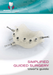
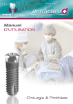
User’s
GUIDE
Surgery & Prosthesis
2
Introduction
euro teknika is the result of 20 years of clinical applications and 24 years of research and development confirmed
by valuable help of international research laboratories.
</b><m>
The design of our implants is based on the skills of our teams which are both reactive and experienced in implantology:
Technical and biomechanical skills of our engineers enabling to guarantee the resistance of the component and
their adaptation to the oral environment thanks to modern means of simulation.
Biological and physiological skills of the associated laboratories enabling to validate the capacity of osseointegration
of our systems.
Clinical and practical skills of our dentists advisers ensuring the ergonomics of our products, the confirmation of
our protocols and the ranges adapted to the various clinical cases.
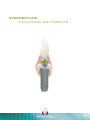
natea+ implants are relied on the most new advanced scientific knowledge regarding implant treatment, which
provides this implant an optimal capacity of anchoring with a strong osseointegration, in particular in the cortical
bone area.
To enable you to take the best advantage of the natea+ implant, we created this manual with a professional care.
We invite you to read it with your best attention. Each detail, even the least important, has its importance and
underlines even more the difference between the beginner and the specialist.
3
4
Summary
Warning
p. 6
General information
p. 7 to 9
Pre-implant study
p. 11 to 14
Surgical procedure
p. 15 to 39
FOREWORD
NATEA+ IMPLANT
THE KIT
PROTOCOL
by bone density and implant diameter
step by step
HEALING PROCESS
P. 16
P. 18
P. 23
P. 28
P. 30
P. 40
Impression techniques
WITH PICK-UP IMPRESSION COPING
WITH POP-IN IMPRESSION COPING
WITH POP-UP IMPRESSION COPING
p. 43 to 47
P. 45
P. 46
P. 47
Prosthetic procedure
p. 49 to 72
FOREWORD
CEMENTED PROSTHESIS
on trans-screwed abutment
on solid abutment
ZIRCONIA PROSTHESIS
on titanium abutment
SCREWED PROSTHESIS
on ConHex abutment
on Plural abutments
on Tetra abutments
OVERDENTURE
on O’Ring abutments
P. 50
P. 52
P. 56
P. 62
P. 66
P. 68
P. 71
P. 73
For more information on euroteknika,
implants, please visit our complete internet website,
www.euroteknika-implants.com
5
Warning
The placement of euro teknika implants must be done by a practioner who has been previously trained for the
dental implantology techniques and in aseptic conditions specific to this type of treatment.
</b><m>
The following instructions will guide you throughout the different stages of your implantology treatments. They
contain advice as precise as possible but cannot be used as «recipes», every clinical situation must be evaluated
for each patient. A great number of factors acts independently to obtain success in an implantology treatment. It
is up to the practioner to recognize the key factors and to use his clinical experience. Among other aspects, the
coordination between the prosthesis laboratory dental technician and the practioner must be perfect so as to give
the global treatment plan more consisting. Only the practioner remains responsible for his different choices and
decisions as to the treatment’s feasibility, implants, prosthetic parts, materials used and settings... The technical
specifications and clinical advice in this manual are given solely as a guideline and cannot give rise to any claims.
All the essential information is indicated in the instruction for use supplied with products.
We have taken great care in the design and production of our products. However, we reserve the right to bring
modifications or improvements arising from new technical developments in our implantology system.We will advise
of any modifications having an implication in the operation mode. According to the importance of the modifications,
a new manual will be issued. Indeed, a mark on the back page indicates the date of issue of your surgery manual,
and enables us to check if you have the latest update version. You will also be able to access our web site to check
the latest version of this manual.
The reproduction and distribution of all or part of this manual need previous agreement from euro teknika.
</b><m>
6
GENERAL
INFORMATION
7
General INFORMATION
natea+ implant GENERAL INDICATIONS
The euroteknika dental implants are suitable for oral bone implantation at the mandible and maxilla and for oral
aesthetic restoration of fully or partially edentulous patients (except in the presence of specific indications and
contra-indications hereinafter mentioned). euroteknika dental implants can be used for differed, immediate or early
loading after a tooth extraction or loss. euroteknika implants are suitable, in the framework of their indications, for
immediate restoration of fully or partially edentulous jaws.
A good primary stability and a suitable occlusal load are paramount. The healing duration for differed restorations
is indicated at the corresponding chapter. Commonly used prosthetic restorations are single crowns, bridges and
full or partial prosthesis, connected into the implants by prosthetic components specific to the implant being used.
You will find at the following pages, for each implant, detailed information about the necessary bone volume, the
space between two implants and the distance to respect with the adjacent tooth.
Lack of retention of a prosthesis
Instability of a prosthesis
Functional discomfort with the prosthesis
Psychological refusal of the wearing of a prosthesis
Parafunctional practices which compromise the
stability of a prosthesis
Inadequate localization and number of remaining
abutments
Lack of dental abutment to perform a fixed prosthesis
Edentulous area with healthy adjacent teeth
Dental agenesis
Request for a preservation treatment (refusal of
alteration of healthy teeth)
They are supra-crestal implants designed to be placed in two-steps surgery, with a Morse tapered connection.
The immediate connection of an healing abutment will enable to work in one-step surgery.
Specific indications for 6 MM LONG IMPLANTS
As the anchorage surface of these implants is limited, they should be used only for the following indications:
as complementary implants to longer implants in a multi-unit or full restoration,
to support full prosthesis, in case of a very atrophied mandible,
on implant sites of a bone quality higher to D4 according to the Misch classification.
Contra indications to the use OF THE IMPLANTS (REMINDER)
Absolute contra indications
severe medical diseases
bone metabolism disorders
uncontrolled hemorrhagic disorders
healing disorders
major psychological disorders
functional disorders
risky cardiopathy
incomplete maxillary and mandible growth
uncontrolled systemic pathology (endocrine
diseases, xerostomy, allergy to titanium)
infectious, hematological and immune pathology
(immune disorder)
alcoholism, medication or drug addiction (regular
steroid use)
8
patients with little motivation or cooperation
age of the patient (young patient during growth)
poor hygiene of the patient
Relative contra indications
use of anticoagulants, hemorrhagic diathesis
insufficient volume and / or an osseous quality
a poor oral hygiene
temporomandibular joint disorder
an insufficient restorative space
if a sinus lifting is needed with the implant
a patient presenting risks (patient exposed to
atomic radiation, bruxism, uncontrolled parodontitis,
addiction to smoking)
Garantee
In case of non osseointegration, you must inform your commercial representative so that we can examine the
causes for the failure and bring the necessary corrective actions. An exchange may take place when the defect of
the product is established; if the failure results from an incorrect clinical analysis, a surgical protocol not adapted to
the case, from the use of blunt drills...or for any other reason independant from the product quality, the guarantee
will not be taken into consideration.
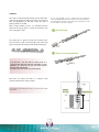
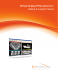
Parts PACKAGING
Sterility and rule of asepsis
Most of our parts are delivered sterile and can therefore
be used straightaway. A reference indicator shows the
components effective sterility on the packaging. The
sterility is guaranteed for 5 years (from packaging date).
A standard expiry date is indicated on the label.
Only an undamaged packaging can guarantee the
products imperviousness and sterility. Do not use
implants with packaging which has been damaged or
prematurely opened.
Our products have been designed so as to enable
handling without affecting their sterility. It is therefore
important to follow a precise handling technique so as
x
Cover screw
(Supplied with implant)
x
No sterile
x
Drills
Store in a dark place
!
Be careful see detailed description
Euroteknika
Made in France
Date of manufacturing
natea
!
Implant NATEA+ ø 41 42 Lg 12 mm
NATEA+ Implant ø 41 42 Lg 12 mm
(Titane)
SB1210121863
2017.10
Complying with European requirements directives
regarding medical plan 93/42 CEE
Don’t use if the packing is damaged
NIDP 41 42 120
2012.10
Store in a dry place
Use until
See the instruction manual
Sanitation method using radiation
0499
2 labels for the patient’s file
of the practioner who placed
the implant and/or of the
correspondent.
1 label for the patient.
Implants
Manufacturing
Ref
Our implants are delivered
with 2 principal labels and
one removable label clearly
showing the mark, the
reference and the batch
number (for a total of 3 labels):
Sterile
QR code for rapid and simple
access to the user manual
Lot
Batch
Labels
not to compromise the conventional hygiene conditions
associated with the implant practice.
The non-sterile instruments and items delivered used
for the implantology treatment must be decontaminated
and, according to a tested process, sterilized at the
practice.
Product reference number
Don’t reuse
25kGy mini.
Serial number
Don’t sterilize twice
Storage OF THE PRODUCTS
The implants must be stored in a clean, dry and cool place.
Precautionary MEASURES
It is strongly advised to keep in stock implants which
cover the most frequently used diameters as well as the
different lengths.
It is important to be able to change an implant’s choice
during a procedure, to replace an implant which has been
contaminated for any reason, to insert an extra implant in
certain cases to insure the long term treatment success...
We recommend to use a safety thread on the
instruments to avoid any accidental fall of tools in the
patient’s throat.
It is strongly advised to prepare the receiving socket
with euroteknika instruments shown in this manual.
9
10
PRE-IMPLANT
STUDY
11
Pre-implant STUDY
It is necessary to evaluate the possibility of an implantology treatment and to
determine the treatment plan.
IMPLANT treatment feasibility
This study takes different elements into consideration
A patient’s questionnaire to reveal potential health
medications problems which could have a bearing
on the treatment success, alcohol, use of tobacco or
drugs, general dental hygiene...
An oral examination which will give details about the
mouth opening, the ligne of the patient’s smile (if is it a
gingival smile), the coronary height and the volume of
bone available, the type of occlusion...
Biological tests (glycemy...)
A complete X-Ray file showing the available bone’s
volumes.
Complete tests studies with the two dental arches
in occlusion.
An implant treatment cannot be started without a
thorough cleaning of all the patient’s infectious seats.
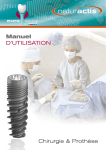
Guide for the IMPLANTS CHOICE
Available bone volume
Bone quality
In the mesio-distal plan
It is recommended to use larger implants in low density
bones to compensate the reduced bone/implant
surface contact.
Leave 2 mm between the implant’s thread and
natural teeth.
Leave 3 mm between the thread of two implants.
Recommended
length
Leave, if possible, 1.5 to 2 mm of bone thickness
around the labial, palatal & lingual surfaces.
Bone quality
In the labio-lingual palatal direction
D1
8 mm
D2
10 mm
D3
12 mm
D4
12 mm
Natea+
Ø implant
Ø 3.6
Ø 4.1
Ø 4.8
Ø6
Ø neck
3.7
4.2
4.9
6.2
The classification of osseous structures*
1: very high density of compact bone
2: thick layer of cortical bone around a dense core
of spongious tissue
3: thin layer of cortical bone around a big core of
spongious tissue
4: thin layer of cortical bone around a big core of
low density of spongious tissue
12
A: important quality of remaining alveolar bone
B: limited resorption of the alveolar bone crest
C: important resorption of the alveolar bone crest
D: beginning of the basal resorption bone
E: important resorption of the basal bone
* Misch, (1998) Lekholm and Zarb (1985), Classification of partially
edentulous arches for implant dentistry.
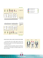
Maxillar
Caption
Natea implant Ø 3,6
Natea implant Ø 4,1
< Implants Ø
Natea implant Ø 4,8
Natea implant Ø 6
<
8
8
8
5
9
5
5
5.5
5
5.5
5
7.5
4
3.5
Mesio distal
length of the
maxillar teeth
Mesio distal
< length of the
mandibular
teeth
< Implants Ø
Mandible
Dimensions of the crown and occlusal loads
YES
NO
YES
The implant table must be, ideally, slightly smaller than the
prosthetic crown to insure the widening of the soft tissues and
the prosthesis emergence. The ratio crown height/implant height
must always be below 1.
A molar replacement must be done with either 2 implants of
small diameters or with an implant of large diameter so the support
cusps are located in the implant’s axis (better distribution of the
forces on the bone ).
8
8
13
Pre-implant STUDY
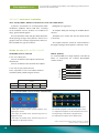
Use of the SURGICAL TRANSPARENCIES
In order to guide the choice of the implant in terms of length and diameter, euroteknika has developed surgical
transparencies that show the dimensions of its different implants. Thereby, the implants are represented with 1:1,
1.3:1 and 1.7:1 magnifications (magnifications correspond to the usual magnifications of the different types of
medical imaging systems: retroalveolar X-ray, X-ray dental panoramic and tomography analysis SCANORA, CBCT
(Cone Beam).
When the practitioner accurately knows the magnification of the pre-surgical X-ray, and if this magnification is 1:1,
1.3:1 or 1.7:1, by a simple superposition of the corresponding template (1:1 template for a 1:1 magnification, 1.3:1
template for a 1.3:1 magnification and 1.7:1 template for a 1.7:1 magnification), it is possible to determine which
type of implant can be placed in the available bone volume.
When the practitioner does not know the magnification of the X-ray or to avoid any mistakes, he may place a
reference object with known dimensions in the mouth of the patient when performing the X-ray examination in order
to determine the associated magnification :
Magnification =
dimensions of the reference object measured on the radiograph
real dimensions of the reference object
The real dimensions of the reference object shall be known to a minimum accuracy of ± 15µm. The reference object
shall be held in position using wax for example or by embedding the object in a partial impression. Care should be
taken for the patient not to swallow the reference object. Use a safety thread if the geometry of the reference object
allows it.
Then, if the calculated magnification is 1:1, 1.3:1 or 1.7:1, you may use the transparencies.
In all cases, if the magnification is not 1:1, 1.3:1 or 1.7:1, it is not possible to use the transparencies provided by
the euroteknika but the bone volume may be determined thanks to proportionality calculation using the X-ray
and the measured magnification.
In this pre-implantation phase the practitioner must also design the coming prosthetic construction since
implantology must be considered as a prostheticaly driven project. Indeed, pre-prosthetic planning and surgical
planning are closely linked and any change to one will have consequence on the other. It is during this phase that
we may determine the number of implants, their diameters, their lengths, their locations and their orientations in
order that we may proceed with the planned prosthetic construction.
14
natea
SURGICAL
PROCEDURE
15
Surgical PROCEDURE
Foreword
Warnings
Treatment planning and placement of dental implants require specific considerations. Practitioners are recommended
to take practical training in order to learn proper techniques, including biomechanical requirements and radiographic
evaluation.
Improper techniques in either implant placement or restoration can result in implant failure and significant loss
of surrounding bone. Drilling sequences to place implants refer to a specific depth measurement and to unique
reference points for each system.
The clinician should refer to the corresponding manual to see the description of the measurement system
specific to the selected product, before applying it to the patient. Every implant system has specific measurement
characteristics. As a consequence, the surgeon must be familiar with the measurement system being utilized in
order to be able to provide safety margins adjacent to any anatomical structure. Failure to respect these measures
can result in permanent injury.
Each system has specific design characteristics. Combining non compatible components can lead to mechanical
failure of components, damage to tissue or unsatisfactory results on the clinical or esthetic level.
For all the euroteknika implants, the preparation of
the implant site is carried out in 3 steps:
1. Initial preparation of the implant site (marking of the bone and first drilling)
2. Calibration of the implant site (bores, drillings and/or tapping)
3. Implant placement (picking-up, screwing, stabilization and suture)
16
Precautions for use
For all the surgical procedure, the following instructions must be observed and respected:
Make sure you have a sufficient number of implants and sterile instruments
All the instruments must be sterile, complete, checked and functional, especially the measurement instruments
(calibrated according to the manufacturer’s recommendation) and the cutting instruments should not be used more
than 10 times.
All the reusable products must be disinfected, cleaned and sterilized.
All the disposable components delivered non-sterile must be disinfected, cleaned and sterilized before intra-oral
use. Using a thermo-disinfector and a Class B autoclave is possible for the components out of their package, in a
specific bag according to the manufacturer’s recommendations.
In case of plastic or ceramic components, always disinfect and cold sterilize with CHLORHEXIDINE.
Any product delivered sterile (by gamma radiation) must not be re-sterilized.
Respect the sterile parts of the package when opening it and place its content on a sterile field.
Respect the expiry date of the product.
For stainless steel, the use of sodium hypochlorite is prohibited: high risk of corrosion.
Respect the different combinations of materials when cleaning and decontaminating them in order not to damage
the components.
Detergent and disinfectant solutions must have a neutral pH or a low alkaline level.
Any preparation of the implant site with cutting instruments on contra-angle requires profuse irrigation with a
sterile saline solution (NaCI).
Respect the sequence of the recommended instruments with a permanent control of the implant axis and depth
according to the planned prosthetic restoration.
Make sure to minimize the thermic and surgical traumatism and to eliminate any contaminant and any infection
source which may cause a failed osseointegration or poor esthetic result.
Secure the instrument and implant components handling and from the risk of fall in mouth or out of the sterile
field because of their small sizes. Make sure they are properly gripped on the instruments.
17
Surgical PROCEDURE
NATEA+ IMPLANT
Features
Ø 3.7 - 4.2 - 4.9 - 6.2
0,4 mm
bone level
Smooth
Light conicity
«cortical support»
Natea+ is a polyvalent implant intended to be placed
at a bone level position. Its cylindrical shape make it
suitable for hard densities.
Microthread 2.9 mm
Applications
Sandblasted & etched length
Ø 3.6 - 4.1 - 4.8 - 6
Real screw
thread
1.60 mm
Thread
0.8 mm
0.3 mm
Double
asymmetrical
thread
References
Implants Ø 3,6 -> Ø 6
The implant is supplied with
a cover screw.
18
Length L
Ø 3,6
Ø 4,1
Ø 4,8
Ø6
6 mm
NIDP 41 42 060 NIDP 48 49 060 NIDP 60 62 060
8 mm
NIDP 36 37 080 NIDP 41 42 080 NIDP 48 49 080 NIDP 60 62 080
10 mm
NIDP 36 37 100 NIDP 41 42 100 NIDP 48 49 100 NIDP 60 62 100
12 mm
NIDP 36 37 120 NIDP 41 42 120 NIDP 48 49 120 NIDP 60 62 120
14 mm
NIDP 36 37 140 NIDP 41 42 140 NIDP 48 49 140
Direct implant driver
Time saving during surgery.
The insertion level and the connection orientation
are easier to see.
Informs about gingival height.
Hexagon
Taper 11°
Astra & Naturactis / Naturall+
compatibility
Even though it has its own prosthetic range, the
Natea+ implant, with its hexagonal internal connection
(morse taper), benefits from an Astra Ocean compatible
prosthetic range common with the Naturactis /
Naturall+ implants.
2,8 mm
Airtightness & stability
The internal conical connection (Morse Taper)
guarantees the airtightness and the stability of the
abutment-fixture connection (S.Dibart, M. Washington,
M. Fan Su, Z. Skobe).
The connection has an internal hexagon which allows
the abutment to be orientated at the right angle.
The depth of the connection (2.8mm) and the quality of
the joint between the parts guarantee a great stability
while putting the pieces together and prevent the
prosthetic from unscrewing.
19
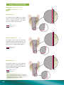
Surgical PROCEDURE
Emergence switching
The assembled implant-abutment is not linear in profile,
but has a concavity coronal to the fixture head as the
abutment is narrower than the external diameter of the
implant. This allows for the development of a ring of
connective tissue that brings :
Mechanical stability of soft tissue
Protection of the biological seal by reducing the risk
of trauma to the soft tissue
The concavity formed by the prosthetic junction
isolates any inflammatory tissue. The 3mm of
biological space needed to isolate & protect the crestal
bone from the external environment is achieved by the
greater length (A) of the prosthetic junction concavity
rather than just the height (B).
The concavity formed by the implant abutment
prosthetic junction isolates any inflammatory tissue
from the bone crest (see Fig 2). Richard J. Lazzara,
Stephan S. Porter (PDR, volume 26 n°1, 2006)
Fig. 1
Assembly type “Platform switching”
Spread surface
A
B
A>B
B = crown/bone distance
A = mucous attachment surface
Fig. 2
Inflammatory zone
Healthy
gingival
against the bone
euroteknika exclusive microthread
Mechanical anchorage to enhance the implant
stability in critical sites made up of the endo-bone neck
that suffers most of masticatory forces.
A thicker microthread for a higher resistance to
tear constraints.
Synchronicity with the main thread in order not to
wrest bone when following it.
A unique design with 6 entries to guarantee the
microthread anchorage in a precise, calibrated, similar
and undamaged track.
Continuity with the microthreads, the protrusions
and macrothreads for a better load distribution along
the implant.
20
The active
insertion of the
microthread in
the cortical zone
First bone pit
made by the min
thread
A
B
A tapered neck for a better primary
stability with a cortical support
Stabilization of the implant notwithstanding a poor
apical bone density.
A controlled implant insertion for a guaranteed
primary stability.
Double threads
Fast screwing of the implant.
Reduced bone heating when screwing the implant.
A central protrusion between threads
Increases surface contact with bone to enhance
osseointegration. Cellular reconstruction is activated
by this change of geometry.
An asymmetric thread
The thread directly influences effective surface of
the implant (B.I.C).
Allows a better occlusal load distribution.
Non traumatic and active apex
A groove closer to the apex to enhance the selftapping effect of the threads.
The threads start from the apex for a high self-tapping
ability of the implant and a better apical anchorage.
A safe use in risky sites (sinus, dental nerve…).
21
22
SURGICAL KITS
The stake for the realization of the implant socket is on
two levels:
A calibration of the socket to obtain a good
primary stability of the implant, main condition for the
osseointegration.
Minimum overheating to avoid all irreversible bone
necrosis. The socket preparation will be made under
constant external irrigation with sodium chloride at
0.9%. The critical temperature threshold is 47°C for
1mn. At 50°C the necrosis is irreversible.
Obtaining a calibrated socket assuring a good
airtightness.
The instruments are sorted by their stage of use as
shown by arrows on the kit. Numbers notify the main
steps of each stage.
BE CAREFUL
It is necessary to choose the prosthetic parts before the
implant placement in order to insert the implant at the
right place.
WARNING
The minimum heating will be achieved with irrigation
and with a proper selection of drills with a good cutting
power. It is therefore necessary to check the number
of use of the drills involved in the implant socket
preparation.
Use the cursors in the surgical kit and change your
drills after 10/15 uses.
Readability of the sequences
23
Surgical PROCEDURE
Surgical KIT
This surgical kit offers all the instruments necessary to achieve the surgical protocol and to manage all
the bone densities for natea+ implants Ø 3.6 - Ø 4.1 - Ø 4.8 - Ø 6.
Free additional spaces
to insert the 3 specific
drivers and 2 mandrels for
Aesthetica+² or Uneva+
implants placement.
Contents:
External hexagonal keys: long, medium & short
Implant direct keys: short, medium & long
Click wrench
Square key for taps
Implant direct mandrels: short & long
External hexagonal mandrels: short & long
Mandrel extension
Paralleling pins
Paralleling implant gauges
Depth gauge
Point drills
Initial cylindrical drills Ø 2.2 - lg. 8, 10, 12, 14 mm
Intermediate cylindrical drills
Cortical drills for each implant diameter
Very hard bone drills
Stops for drills
Drill stop tool
Gingiva gauges
24
Ref. NIDT P6
Mini SURGICAL KIT
CONTENTS:
Ref. NIDK P 36 4X
Medium external hexagon key
Medium key for direct handling
Click wrench
Short mandrel for direct handling
Short external hexagonal mandrel
Depth gauges for drills Ø 2.2
Point drill Ø1.5 - Ø 2.2
Initial drills Ø 2.2 length 8,10,12,14 mm
Cylindrical drills
Cortical drills
Final drills
Paralleling implant gauges
In option :
Short external hexagon key
Long external hexagonal mandrel
Short key for direct handling
Long mandrel for direct handling
Tap wrench
Extension mandrel
Paralleling pins
Taps
25
Short implants SURGICAL KIT
Ref. NIDK P 48 6
CONTENTS:
Click wrench
Implant direct keys:
short, medium and long
External hexagon key
Implant direct mandrels:
short and long
External hexagonal mandrel
Mandrel extension
Depth gauge
Paralleling pins
Point drill Ø 1.5 - 2.2
Initial drill Ø 2.2
Cortical drills
Final drills
Drill stops
Surgical SEQUENCER
Ref. CSC 7 20 - empty delivered
This allows you to set out the implants and instruments
in the order necessary for a specific surgical procedure.
3. Picking up the implants
2. Opening the implant packaging
4. Picking up the healing abutments
{
1.
26
First sequence of drills
Second sequence of drills
27
Surgical PROCEDURE
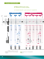
PROTOCOL
BY BONE DENSITY AND IMPLANT DIAMETER
IMPLANTS Ø 3.6
IMPLANTS Ø 4.1
Lengths 8 - 10 - 12 - 14 mm
Point
drill
Drill Ø 2.2
with stop
D4
D2/D3
Ø 2.8
Ø3
D1
D4
Ø 3.3
DRILL
1200 rpm
D1
D2/D3
à
â
Ø 3/3.6
D1
Ø 3.5
à
â
à
â
800 rpm
Ø 3/3.6
D2/D3
à
â
800 rpm
Ø 3.5/4.1
Ø 3/3.6
Ø 3.5/4.1 Ø 3.5/4.1
Ø 3.5/4.1 Ø 3.5/4.1
CORTICAL DRILL
1200 rpm
Lengths 8 - 10 - 12 - 14 mm
lg 6
400 rpm
or
Ø 3.6 or
or
Ø 4.1
Ø 4.1
Ø 3.8
Ø 3.3
Ø 3.8
TAP
DRILL
FOR D1
(NOT INCLUDED IN THE KIT)
400 rpm
OR
25 rpm
800 rpm
option
25 rpm
800 rpm
option
25 rpm
800 rpm
option
from 15 to 25 rpm
Ø 3.6
Ø 3.6
Example of insertion for a 10 mm
long implant, the same as for the other lengths
of implants.
28
Ø 4.1
Ø 3.6
!
Ø 4.1
Ø 4.1
The protocol for a 6 mm long implant
is different.
Ø 4.1
Ø 4.1
IMPLANTS Ø 6
IMPLANTS Ø 4.8
Lengths 8 - 10 - 12 - 14 mm
lg 6
D2/D3
D1
D4
Ø4
D2/D3
D1
Drill
Ø 4.8
Ø 4.2
à
â
à
â
à
â
Ø 4.2/4.8 Ø 4.2/4.8 Ø 4.2/4.8
Ø 4.8
Ø 5.4/6
Ø 5.4/6
or
option
à
â
â
600 rpm
Ø 5.4/6
Ø 5.4/6
or
Ø6
Ø6
Ø 4.5
Ø 4.5
600 rpm
D1
Ø 5.4/6
400 rpm
or
25 rpm
D2/D3
600 rpm
400 rpm
Ø 4.8
D4
Ø 5.4
600 rpm
Ø 4.2/4.8
D1
D2/D3
Ø 5.2
à
â
600 rpm
Ø 4.2/4.8
Lengths 8 - 10 - 12 mm
lg 6
25 rpm
or
Ø 5.7
600 rpm
25 rpm
option
Ø 5.7
600 rpm
25 rpm
option
option
600 rpm
from 15 to 25 rpm
Ø 4.8
lg 6
Ø 4.8
lg 6
Ø 4.8
Ø 4.8
Ø 4.8
Ø6
lg 6
Ø6
lg 6
Ø6
Ø6
Ø6
29
Surgical PROCEDURE
Protocol STEP BY STEP
1
The following illustrations represent the drilling
sequences for Natea+ Ø 4,1 in a medium and dense
bone density. For the other implant diameters, please see
protocol on page 26-27.
Preparation of the implant site
BE CAREFUL
Prepare the access to implant site via a crestal incision
through the attached gingival tissue and raise a partial
thickness flap. The flap should extend to allow for proper
visualization of the site and adjacent tooth root when
required. A partial thickness flap is made at the proposed
implant site. The reflection on the flap is made large
enough to visualize the adjacent roots and not into the
papilla areas in an effort to preserve this tissue. In the
edentulous area, the incision is made at the crest of
the ridge and reflected for access. If minimally attached
gingiva is an issue, avoid over reflection of the tissues into
the sulcus to preserve the attachment.The crestal incision
is often made towards palate for aesthetic reasons or
when the quantity of the attached vestibular gingiva is not
enough.
Maintain a minimum space around the implants according
to the common rules in implantology.
In the labio-lingual / or palatal direction save 1.5 mm
to 2 mm of bone.
In the mesio-distal plan, save 2 mm between a natural
tooth & the implant thread, or 3 mm between 2 implants
threads.
The width of the implant neck must be taken into
account for the implant placement. Our gauges show the
neck width to help place the implants with precision.
To anticipate the necessary space between the necks
of implants:
Ø implant
Ø neck
2
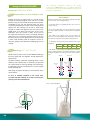
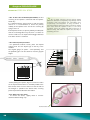
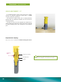
Marking OF THE BONE
Set the motor speed at 1000 to 1200 RPM according to
the bone quality and start irrigation. Visually pinpoint the
implant areas.
The bone marking is made with a pointing drill of 1.5 mm
diameter, more effective than a round bur. The pilot drill
has a point which can easily go through the cortical layer.
Its upper part, with a 2.2 mm diameter, is used as a guide
for the following drill.
3,6
4,1
3,7
4,8
4,2
4,9
Ø 3 mm
Ø 2,7 mm
Ø neck
3.9
Ø neck
4.8
4.8
Ø 2.2
Ø 2.2
Axis of point drill Ø 2,2
Depth
drilling
5
mm
Ø 1.5
angle of cut 90°
30
Ø 2.2
6,2
The Ø 3,9 or 4,8 shoulder of paralleling pins enable to
preview spacing between the implants and thus to place
the adjacent implants by leaving enough space between
them.
After being used, place the drill in a steel container with a
saline solution.
In case of multiple implants in the same area,
proceed with the marking of sockets following the
spacing rules described above.
6
Ø 1,5 mm
3
Control OF THE SOCKET AXIS
After the point drill using, check the axis of the first
sockets by looking at the orientation of the drill mandrel,
or by inserting in the socket the thinnest side Ø 1,5 / 2,2
of the paralleling pin.
5 mm
Ø 2,2
Ø 1,5
4
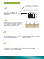
First DRILL
Choice of the length of the
Ø 2,2 mm drill
The preparatory drill allows to determine the axis
and the depth of the implant socket.
The natea+ Ø 2,2 drills are drills with a stop. There
are 5 lengths: 6 - 8 - 10 - 12 - 14 mm.
Remember to make the axial
correction at this stage if it is
necessary. Thanks to the point
drill previously used, the drill
diameter 2.2 will be perfectly
centered and guided at the
entrance of the socket.
Ø 2.2 drill of the length of
the implant to be placed
Achieve the drilling under constant external irrigation
of sodium chloride, and at a speed between 1000
and 1200 rpm, according to the bone quality. The drill
progression must be done without strain. If it is not
the case, it indicates that bone residue are clogging
the drill. An easy backward and forward motion, very
controlled so as to not ovalize the area, will enable
more fluid progression of the drill. This does not require
a reversing of the motor if it is done at the right time.
If the drill is blocked, it can be removed by using the
motor reverse mode.
BE CAREFUL
The rounded end of the implant doesn’t fit until the
very bottom of the socket prepared with the drill. The
socket will be slightly deeper than the implant length.
This avoids any risk of apical compression and
warranties the crestal anchorage in cortical area.
STOP
L = 10
Apical reserve
(from 0,5 to 0,9 mm)
31
Surgical PROCEDURE
Protocol STEP BY STEP
5
Control OF DEPTH
(option)
Check the depth of the socket using
the graduated depth gauge diameter
2.2 (in option - sold separately). This
depth gauge can also allow to control an
hemorrhagic flow.
6
The apical part of the angled gauge also
allows to check the state of the implant socket
(fenestration)
Ø 2.2
6 mm
8 mm
10 mm
12 mm
14 mm
16 mm
18 mm
Control of the SOCKETS AXIS
Insert the thinner side Ø 1,5 / 2,2 of the parallelism
gauge(s) in the implant(s) socket(s) to evaluate the
axis of emergence of the implant(s). The gauge so
positioned can also control a hemorrhagic flow.
7
Bone COLLECT
We advise you to collect the bone fragments resulting
from each drilling in order to be able to correct any
bone defect, or to improve margins of an irregular crest.
The volume of the collected bone is, in most cases,
enough to correct some moderate defects.
8
Following DRILLINGS
Use the diagrams p. 30 and 31 to determine the
succession of the drills corresponding to the diameter
of the chosen implant, and to adapt the implant socket
to the bone quality of the area (see pages 24 and 25).
This information has been transferred on a plasticized
sheet included to facilitate the procedure. During
32
It avoids a transplant/graft and will not even require
to be stabilized if the bone defect has several walls.
Be careful, this bone must be preserved of any
contamination and treated under the same conditions
of asepsis as the implant.
the drillings, verify that the bone bleeds. Should the
opposite occur, scratch a little the bone to make it
bleed. In the absence of vascularization, it’s better to
close and to wait for a revascularization. Drilling speed
should be between 600 and 800 RPM.
STOPS
The stops can be picked up directly on the drill with a
contra angle. Check the alignment of the stop extremity
with the graduation on the drill. Verify the stop is
properly fixed on the drill.
After a large number of uses, it is possible that the
stops do not clip in place as easily on the drill. In this
case, change the stop.
Ex : A stop marked « lg 12 », means that it will enable to
make an implant depth of 12 mm after the stop is placed on
the drill. When mounted on the drill the stop measures 4 mm
as our drills are 16 mm in length.
1 Set the stop
The stops have a groove to help the insertion of the
key. To remove a stop, insert the proper key in the stop
groove and push the stop towards the drill extremity.
p
Sto
2 Stop in correct position
!)
(Click
In a bone D2 - D3, the drills are being used at a
speed between 800 and 1200 rpm depending on their
diameter. In a D1 bone, we can use slower speeds
between 300 and 800 rpm.
The drills must work under constant irrigation.
3.5
After their use, place the drills in a stainless steel
container filled with a saline solution.
If you wish to work without the stops, you can use the marks
on the drill.
3.5 x 12
Fig.1
Implant
L = 12
L
12
10
8
6
Stop 12 mm.
L = 12
33
Surgical PROCEDURE
Protocol STEP BY STEP
9
0.4 mm
Terminal DRILLING
Soft bone D4
To enhance primary stability, the implant
socket is 0.8 mm undersized compared
with the implant diameter. The whole
thread is compressed in the bone.
Better stability
Implant socket
Thread tops
0.3 mm
Normal bone D2 - D3
The implant socket is 0.6 mm undersized
compared with the implant diameter. The
thread is compressed in the bone until its
basis to ensure a good primary stability.
Implant socket
Thread tops
Hard bone D1
0.15 mm
The implant socket is 0.3 mm undersized
compared with the implant diameter. The
thread is partially compressed in the bone to
ensure a good primary stability.
Implant socket
Thread tops
! To avoid problems with osseo-integration
due to over-heating of bone, drills for hard bone
are calibrated to prepare the implant site to a
slightly larger diameter than normal.
34
Minimum heating
Tapping
This procedure is optional; it depends on the bone
quality and on the wanted level of compression on the
bone. To eliminate any overheating usually caused by
this procedure, euroteknika supplies taps that only
feature an active part limited to a reduced number of
threads. The shape of the tap allows for just a few of the
thread cutters to touch the bone in a forward rotation.
Once to depth, the tapping cutters only minimally touch
the bone again during the reverse rotation coming out of
the bone site preparation.
In most of the cases, it is advised to only thread the
cortical part of the bone socket to facilitate the insertion
of the implant while optimizing the primary stability of
the implant.
The tap is used either with a contra-angle at a speed of
15 to 20 rpm or manually with a tap wrench.
10 Depth GAUGES
Dimensioned to the final diameter (3 - 3.5 - 4.2), they
enable a last check of the depth of the socket. They are
graduated like the drills, i.e. every 2 mm, from 6 mm to
16 mm.
! Once the depth gauge is placed in the bone, you
should not see the graduation which must not appear
above the bone
11
Cortical DRILL
Use the cortical drill after the cylindrical drill
according to the protocol of bone density (p. 26-27) at
a speed between 300 and 400 rpm maximum.
Use the cortical drill with the same color code as the
implant diameter.
This stage is required in all cases whatever the hardness
of the bone is, to ensure cortical compression onto the
implant neck.
35
Surgical PROCEDURE
Protocol STEP BY STEP
6
5
4
Lines to measure
gingival heights from
the crestal ridge.
The implant can be inserted manually or with the
12
Implant INSERTION
handpiece. This procedure must be done with the
greatest care so that the implant does not come in
contact with any non-sterile element before insertion in
the bone socket. To do so, use the screwing mandrel
or manual key. After opening the tube, connect the
appropriate implant driver directly to the implant without
taking it out of its casing before.
3
2
1
Mark indicating that the driver
is inserted. This mark should
disappear when properly
inserted in the implant.
Torque
transmission
area
Retention area in
the extremities of
the 6 sides
12.a The implant should be taken out of its casing
as follow:
2.
1.
Step 1 - Seat the hexagon of the mandrel or key into the
implant hexagon.
Step 2 - To seize the implant, slightly rotate the mandrel or
key in the implant, in clockwise direction, until the implant
stops turning in its casing (a device in the casing allows to
limit the implant rotation while grasping it).
Step 3- Insert the mandrel into the implant by applying light
pressure so that it is retentive on the implant (5N= 500g).
a. The positioning marking is not visible any more,
the mandrel is correctly seated.
b. The positioning marking is visible, the mandrel is
not oriented nor inserted properly. In that case, go
back to step 1
a.
ok
c. The positioning marking on the mandrel is visible,
the mandrel is not oriented nor inserted properly. In
that case, go back to step 2.
Step 4 – The mandrel is properly seated in the implant,
apply light pressure counter-clockwise.
Step 5 – Take the implant to its receiving site.
Note: Be careful with the risk of fall on the floor or in the
mouth when taking the implant.
b.
36
c.
12.b For a good positioning with the handpiece,
we recommend a speed of 15 to 25 r/mn to control the
insertion of the implant. The positioning with the
handpiece enables to measure the insertion torque of
the implant and to evaluate its primary stability.
We recommend to set the implant at 30 N.cm minimum
for a delayed loading, and higher than 40 N.cm for early
or immediate loading. Never exceed an insertion torque
of 70 N.cm.
Bone D1 - D2
For D1-D2 bone, it is recommended (during the
screwing of an implant with a contra-angle), to finalize
the screwing with the torque wrench, in order to ensure
the good insertion of the implant.
1
Screw with the
handpiece
2
Finish screwing
with the torque
wrench
37
Surgical PROCEDURE
Protocol STEP BY STEP
12.c In the case of manual placement, the first
screwing of the implant is achieved with the implantholder key.
It is finalized with the click wrench or with the torque
wrench. It is recommended to check the primary
stability of the implant at the end of the screwing by
trying to move it.
If the implant can move, its primary stability is inadequate
and the osseointegration may fail; then it is better to
remove it and to use an implant with a bigger diameter
if the bone volume is sufficient.
! Do not apply excessive pressure during implant
placement. Excessive overtightening may damage internal
connection and over-compress the surrounding bone,
compromising osseointegration. If strong resistance is
encountered during tightening, lightly unscrew the implant
then insert back the implant. If there is still strong
resistance, remove the implant and place it back into its
titanium casing, and widen the implant site according to
the drilling protocol.
12.d Final implant placement
- For optimized aesthetic results, place the implant
at bone level. Use the depth sign on the key or the
mandrel.
The angled gauge (in option - sold separately) and
the paralleling pins can also allow to measure gingival
height.
6
5
4
3
2
1
Ø 3.8
crestal ridge
0 mm
0
0,5 mm
1.5 mm
2.5 mm
3.5 mm
4.5 mm
5.5 mm
6.5 mm
7.5 mm
8.5 mm
9.5 mm
- When placing the implant, align one of the hex sides
on the implant manual driver or mandrel parallel to the
buccal wall, which ensures that one of the flat side of
the hexagon is parallel to the buccal side, ensuring
preferred prosthetic abutment orientation.
12.e Removal of the driver
- To remove the driver, slightly rotate it counterclockwise before lifting it up.
Vestibular flat side
38
13
Protection OF THE CONNECTION
It is ensured:
Either with a cover screw if the treatment includes
a second surgical stage:
It is supplied in the cap of the implant tube, and can be
taken with the hexagonal key. The best way to pick it up
is to turn the cap around the key (rather than actioning
the key). In this case, the suture is made over the cover
screw. It is recommended not to pull too much on the
soft tissues to avoid any exposition of the screw.
Interrupted suture can be made every 2 mm, they should
be socket tightened. If the patient has a provisional
prosthesis, it is recommended to groove the intrados
14
and rebase the denture with a soft resin. If the patient
must carry a prosthesis (in the anterior area), it should
be rebased with a soft resin.
Either with a healing abutment if only one surgical
stage is planned:
Select the most relevant part to get an aesthetic and
natural shape of the soft tissues around the implant.
Screw manually the abutment with the external
hexagonal key at 10 N.cm or with the torque wrench
(ref. CCC35) for a better precision.
Osseointegration
The conventional period to obtain a good
osseointegration is:
- 3 months at the mandibular,
- 6 months at the maxillary due to a different bone
quality.
The dentist should define this period by taking into
account the bone quality, the implant primary stability
and the prosthetic plan.
In certain cases, the dentist can decide to connect the
prosthetic parts without waiting for the osseointegration.
However, the dentist must be able to analyze if the
conditions of the clinical case are appropriate to an
immediate loading.
Studies and scientific datas indicate that immediate
loading has proven to be successful at the mandibular
when the prosthesis is built on 4 implants or more linked
together. Immediate loading is not recommended on a
single implant.
! In case of failure
Try to unscrew the implant with the implant key, the
direct implant driver or an implant extractor. In case you
fail to do so, use a trephine with a greater diameter
than the placed implant and remove the bone cylinder
obtained. Implant removal is facilitated by using an
implant-holder screwed on the implant.
The socket can possibly be re-implanted*:
- if the patient is ready to receive a new implant,
- with an implant of wider diameter, in the case that the
placement of this implant occurs at the same time.
To put another implant with a smaller diameter, it is
better to wait for the complete healing of the socket.**
* It is important that the reasons of the failure are
analyzed before placing a new implant.
** The doctor decides whether it is necessary to use
bone material to fill in the socket.
EXTRACTION KIT
KDR 3N
39
Surgical PROCEDURE
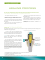
HEALING PROCESS
In case the implant has been placed without being immediately loaded
THE SOCKET IS RE-OPENED 3 TO 6 MONTHS LATER
Use a probe to locate the cover screw.
Open the site with a gingival punch if there is
sufficient attached gingiva on both sides of the crest.
If necessary repel the bone that has been growing
on the cover screws with small enamel chisel or a small
bone trepan.
Unscrew the cover screw with an hexagonal key or
mandrel (reverse mode at low speed).
Clean the top of the implant surface and rinse with
physiological serum.
Measure the depth of gingival sleeve by introducing
a probe through the gingival tissue to the base of the
smooth cone, which is loaded on top of the implant.
Choose a healing abutment according to the
prosthetic plan.
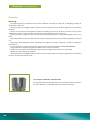
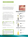
Choice of THE HEALING ABUTMENT
The healing abutment allows to give its shape to the future emergence prosthetic profile while waiting for the
stabilization of the gingival height.
In order to select the most appropriate healing
abutment, the burying depth of the prosthetic joint and
the desired emergence profile have to be defined first.
1. Final prosthetic project to be achieved
A
A & B enable to determine the most appropriate
abutment. The table below shows you the healing
abutment corresponding.
The neck depends on the aesthetic emergence
profile that you want to achieve; the prosthetic abutment
should have the same conicity.
This must be a sufficient angle to have embrasures
for the passage of tooth brush. It must also achieve a
specified distance between contact points of crowns
and the summit of the interdental bone crest (Prof.
Tarnow); this distance must be lower than or equal to
5 m. The angle defined by the conicity must exert a light
pressure on the papilla to stimulate the healing without
risk of necrosis.
B
Localization of the
prosthetic joint at
least 1.5 mm below
the gingiva for an
aesthetic result.
=> Enables to
determine the height
of the B abutment
Healing abutments have a higher diameter (0,4 mm) than the final abutment:
- to avoid gingiva stick and improve patient’s comfort,
- to make the intervention faster,
- for easier and less painful insertion of impression copings and definitive abutments (avoid anesthesia).
40
Healing abutment
Titanium abutment
A
C
B
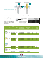
Preparation of the prosthetic profile
Table for the selection of the tissue-level parts emergence
Use a healing abutment which
has a bigger emergence profile
(diameter 0,4 mm) than the
titanium abutment which will be
placed later.
Tighten the healing abutment
at 10 N.cm with the external
hexagonal key.
Prosthetic
profile
ep
ø 3.6
Healing
abutments
ØC
(prepare
gingival profile)
3.8
5.0
ø 5.2
ø 6.0
5,6
6,4
Laser code on the top of the abutment
Prosthetic emergence
indication
Supracrestal gingival height
indication for a crestal (C)
or sub-crestal (S) implant
Platform letter
Emergence
diameter
E (Extra narrow)
N (Narrow)
R (Regular)
W (Wide)
Ø 3.6
Ø 4.6
Ø 5.2
Ø6
Titanium abutment with
a corresponding
emergence profile
Laser
identification
code
Gingival
height B
Supracrestal
height
NCI 36 23
NPS PD 36 06
E C1
1
2.5
NCI 36 34
NPS PD 36 16
E C2S1
2
3.5
NPS PD 36 26
E C3S2
3
4.5
NCI 36 56
NPS PD 36 36
E C4S3
4
5.5
NCI 36 67
NPS PD 36 46
E C5S4
5
6.5
NCI 46 23
NPS PD 46 06
N C1
1
2.5
NCI 46 34
NPS PD 46 16
N C2S1
2
3.5
NPS PD 46 26
N C3S2
3
4.5
NCI 46 56
NPS PD 46 36
N C4S3
4
5.5
NCI 46 67
NPS PD 46 46
N C5S4
5
6.5
NCI 52 23
NPS PD 52 06
R C1
1
2.5
NCI 52 34
NPS PD 52 16
R C2S1
2
3.5
NPS PD 52 26
R C3S2
3
4.5
NCI 52 56
NPS PD 52 36
R C4S3
4
5.5
NCI 52 67
NPS PD 52 46
R C5S4
5
6.5
NCI 60 34
NPS PD 60 16
W C2
2
3.5
NPS PD 60 26
W C3S2
3
4.5
NPS PD 60 36
W C4S3
4
5.5
NPS PD 60 46
W C5S4
5
6.5
NCI 36 45
NCI 46 45
NCI 52 45
NCI 60 45
NCI 60 56
NCI 60 67
ØA
3.6
4.6
5,2
6,0
41
42
IMPRESSION
TECHNIQUES
43
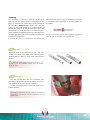
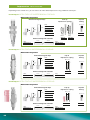
Impression TECHNIQUES
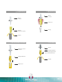
Depending on the clinical case, you can choose to make dental impressions using 3 different techniques:
Technique WITH PICK-UP IMPRESSION COPING
Material required
Pick-up
impression copings
External hexagonal keys
short
medium
13.5 mm
8 mm
Ø 3.5 mm
CCL HE 12 18
10 mm
20 mm
12 mm
CCL HE 12 22
long
NLA H35
CCL HE 12 30
External hexagonal mandrels
22 mm
short
26 mm
CMA HE 12 22
Implant
analog
short
long
NPE T35
NPE T35 L
long
CMA HE 12 26
Technique WITH POP-IN IMPRESSION COPING
Material required
External hexagonal keys
Pop-in
impression coping
short
20 mm
8 mm
12 mm
CCL HE 12 18
Implant
analog
Ø 3.7 mm
medium
Ø 3.5 mm
CCL HE 12 22
long
CCL HE 12 30
NPI 37
External hexagonal mandrels
22 mm
short
26 mm
CMA HE 12 22
NLA H35
long
CMA HE 12 26
Technique WITH POP-UP IMPRESSION COPING
Material required
External hexagonal keys
Pop-up
impression coping
short
20 mm
8 mm
12 mm
Implant
analog
Ø 4.1 mm
CCL HE 12 18
medium
Ø 3.5 mm
CCL HE 12 22
long
CCL HE 12 30
NPU 35
External hexagonal mandrels
short
CMA HE 12 22
44
22 mm
26 mm
long
CMA HE 12 26
NLA H35
1
Technique with PICK-UP IMPRESSION COPING
PROTOCOL
After having unscrewed the healing abutment,
manually screw the pick-up transfer into the implant
using the hexagonal key. Do not exceed the 10 N.cm
maximum tightening torque.
Screw
10 N.cm
You can choose between 2 heights of impression
coping according to your case:
• Short: height 10 mm
• Long: height 13,5 mm
After making sure the transfer is positioned correctly,
make the impression using an open tray and clear the
head of the screw.
Pick-up impression
coping
Once the impression has been made, unscrew the
pick-up transfer using the external hexagonal key.
Implant
Remove the impression.
Screw the analog onto the transfer.
Be careful to always hold the analog and not the
tray.
Important Information
Advantages
Precision
Better accommodates divergent axes
Repositioning errors are impossible (except analog)
Ideal for multiple and single cases
Disadvantages
Long unscrewing time with the tray in place in the
mouth = uncomfortable for patients with problems
swallowing and vomiting
Lengthier implementation, with the removal of the
splint heads and of the impression material
Restricted oral aperture contra-indicated on
implantation sites in the posterior sections
45
Impression TECHNIQUES
2
Technique with POP-IN IMPRESSION COPING
PROTOCOL
After having unscrewed the healing abutment,
manually screw the pop-in transfer into the implant
using the external hexagonal key. Do not exceed the
10 N.cm maximum tightening torque.
Screw
10 N.cm
After making sure the transfer is positioned correctly,
make the impression with a closed tray.
Remove then the impression, ideally in the transfer
axis.
Unscrew the pop-in transfer using the external
hexagonal key.
Pop-in impression
coping
Screw the analog onto the transfer, manually orient
and re-position the transfer into the impression.
Implant
!
Make sure the transfer is inserted and oriented
correctly into the impression.
Important Information
Advantages
Restricted oral opening
Unscrewing after having taken out the tray
= more comfortable for the patient
Ideal for single cases
46
Disadvantages
Precision varies depending on the quality of
impression materials
Possible repositioning errors
The divergence between the implants should be
lower than 20°
Not recommended for multi-unit cases
3
Technique with POP-UP IMPRESSION COPING
Clippable
transfer cap
PROTOCOL
After having unscrewed the healing abutment, manually
screw the pop-up transfer into the implant using the external
hexagonal key. Do not exceed the 10 N.cm maximum
tightening torque.
Screw
10 N.cm
After making sure the transfer is positioned correctly,
install the clippable transfer cap.
• Orient the pink cap rib towards the transfer’s flat plane.
• Clip: hear the insertion “click”.
Make the impression with a closed tray.
Once the impression has been made, remove the tray,
ideally on the transfer axis.
Unscrew the pop-up transfer using the external
hexagonal key.
Screw the analog onto the transfer, then orient and
reposition the transfer into the impression, clipping it into
the transfer cap.
Pop-in impression
coping
Implant
Rib/flat plane
alignment
!
Make sure the transfer is inserted and oriented
correctly into the impression.
It is possible to use the pop-in version using
the screw ref. NPS VTB 16 156.
Align the flat plane of the transfer with
the interior flat plane of the plastic cap
in the impression material.
Important Information
Advantages
Precision
Restricted oral opening
Unscrewing after having removed the tray
= more comfortable for the patient
Ideal for single cases
Disadvantages
Possible repositioning errors
Divergence between implants should be lower than
20°
47
48
PROSTHETIC
PROCEDURE
49
Prosthetic PROCEDURE
Foreword
Warning:
The tightening torques indicated in this manual should be respected to avoid risks of damaging, breaking or
dysfunction of the items.
Check the proper assembling of parts in order not to cause the prosthesis to fail and to guarantee its mechanical
functions.
Secure the instruments and prosthetic components handling from the risk of fall in the mouth or out of sterile
field because of their small sizes. Make sure they are properly gripped on the instruments.
Certain prosthetic components are delivered sterile to be used during the surgery. ATTENTION not to re-use
them.
All the disposable components delivered non-sterile must be disinfected, cleaned and sterilized before intra-oral
use.
Respect the decontamination and/or sterilization rules (plastic or ceramic components cannot be sterilized in
an autoclave).
In case of plastic or ceramic components, always disinfect and cold sterilize with CHLORHEXIDINE.
Any product delivered sterile (by gamma radiation) must not be re-sterilized.
Respect the sterile parts of the package when opening it and place the content on a sterile field.
Respect the expiry date of the product.
Check the proper assembling of parts in order not to cause the prosthesis to fail and to guarantee its mechanical
functions and the final esthetic result.
A unique common connection
The implants Naturactis Naturall+ Natea+ have a unique common connection
for all the diameters, compatible with Astra’s Ocean connection.
50
CEMENTED
PROSTHESIS
4 PLATFORMS
ep
ø 3.6
Ø 3,6
Ø 4,6
ø 5.2
ø 6.0
Ø 5,2
Ø 6,0
51
Prosthetic PROCEDURE
Cemented prosthesis ON TRANS-SCREWED ABUTMENT PROTOCOL
1. After removing the healing abutment, take the
impression with the impression coping into the implants.
2. Unscrew the impression coping
if a pop-in impression coping has been used, the
impression may be withdrawn directly. Impression
coping is then unscrewed, connected to analog, and
then placed back in the impression.
if a pick-up impression coping has been used, the
impression coping must be unscrewed to be removed.
The analog is then connected to the pick-up impression
coping inside the arch of the impression. (see picture
2).
3. Send the impression to the laboratory.
4. The plaster cast model is made at laboratory.
5. The laboratory chooses the abutment: straight
or angulated (7°, 15° or 20 °- see the prosthetic
panorama). The abutments can be customised if
necessary. They are placed on model with a laboratory
screw. (see picture 3)
6. Make the wax-up on the abutment.
7. Cast the wax-up and finalize the crown.
8. Seat the abutment in the mouth with the abutment
screw provided in the pack. Use a dynamometric key
to apply the proper tightening torque. (see picture 4).
If the abutment was fitted some time before, tighten to
the correct torque level once again before fitting the
prosthesis.
9. Take an x-ray to check the fit of the abutment in the
implant.
10. Final adjustment of the finished prosthesis.
11. Cement prosthesis onto the abutment.
* Do not use the final abutment screw in the lab or
for trying of the prosthesis; this would alter its physical
properties.
For try-ins and laboratory work use lab guide screws:
ref. NPS VG 16 200, NPS VG 16 250.
For final fixing in the mouth use a new abutment screw.
! Use the torque wrench for the precise tightening of
the prosthetic parts at 25 N.cm
52
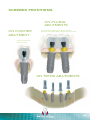
1. SCREWING THE
IMPRESSION COPING
2. CONNECTING THE
IMPLANT ANALOG
Screw
10 N.cm
Screw
10 N.cm
Impression
Pick-up
impression coping
Analog
Implant
3. ON THE PLASTER CAST MODEL
Laboratory screw *
25 N.cm
4. IN THE MOUTH
Screw
Straight abutment
Definitive tightening with the
torque wrench at 25 N.cm
Straight abutment
Implant
Plaster cast
53
54
C E M E N TE D P R O STH E S I S
O N S O L I D AB UTM E NT
55
Prosthetic PROCEDURE
SOLID ABUTMENT USE
A standard protocol using snap-fit impression copings
ensures an accurate impression, which gives a reliably
accurate model of the abutment.
The impression coping snaps onto a small prominence
located above the abutment shoulder (see the red area on
the picture below).
The burn-out sleeves are not snapped on the abutments in
order to allow the technician to remove them more easily and
to avoid reshaping which may compromise the prosthetic
joint.
Impression coping
Easy to fit over the solid abutment without clearing the sulcus.
Snapping
area
Impression coping
Solid abutment
Implant
56
!
Make sure to align the flat plane of the abutment
with the interior flat plane of the impression coping.
PICTURE 1. IMPRESSION ON UNMODIFIED
SOLID ABUTMENT
Two types of impression copings are available:
Impression
coping
When restoring unshortened solid abutments,
use the colored snap-on impression coping over the
abutment in a closed tray.
When the abutment has been modified, use the
white open impression coping over the abutment (see
page 58).
Click
Abutment
Tighten at 35N.cm with the
external hexagonal key and
the torque wrench.
Implant
Protocol
ON UNMODIFIED SOLID ABUTMENTS
PICTURE 2. USE OF ANALOG
1. Choose the abutment height (4 – 5.5 – 7 mm).
Impression
coping
2. Screw the abutment with the torque wrench (ref.
CCC 35) at 35 N.cm.
3. Snap on the coping onto the abutment.
Make sure to align the rib of the coping with the flat
side of the abutment. Then, the impression material
is spread all around the impression coping covering
it completely. This technique gives an accurate
impression of the implant shoulder (information is given
by the coping part and not the impression material).
(Picture 1)
4. Remove the impression and connect the abutment
analog into the impression coping inside the impression.
The snap fit guarantees the correct position of the
analog. (Picture 2)
Click
Analog
PICTURE 3. PROTECTION CAP
Protection cap
Click
Abutment
5. Fit the protection cap on the solid abutment. (Picture 3)
Implant
LABORATORY STEPS
6. Make the plaster cast model.
PICTURE 4. ON PLASTER CAST
7. Seat the burn-out sleeve on the analog and wax up
the framework. (Picture 4)
8. Cast the wax-up.
9. Make the ceramic part of the prosthesis.
Burn-out sleeve
Friction fit
(not snap fit)
Analog
10. The crown is cemented on the abutment in the
mouth after the removal of the protection cap.
57
Prosthetic PROCEDURE
Protocol ON MODIFIED SOLID ABUTMENTS
Adjustments on solid abutments do not allow to fully
enjoy the advantages of a standard impression system.
We recommend applying the following technique only
on single crowns for which the prosthetic adaptation
is less sensitive to inaccuracy of impression copings.
Photo credit : Dr J. BOUCHET (France)
PICTURE 1. IMPRESSION ON MODIFIED
PICTURE 1. IMPRESSION ON ABUTMENT
CUT
ABUTMENT
1. Choose the abutment height (4 – 5.5 – 7 mm).
2. Adjust the solid abutment (respecting the shaping
limit).
Impression
coping
Click
3. Place and tighten the abutment at 35 N.cm.
4. Take the impression with the white open impression
coping snapped onto the abutment. Gentle pressure
allows the impression coping to fit onto the abutment.
Then, the impression material is injected inside and all
around the impression coping until it covers completely
the plastic part. (see picture 1)
Solid abutment
Tighten at 35N.cm with the
external hexagonal key and
the torque wrench.
Implant
5. Protection cap setting onto the abutment during the
prosthesis manufacturing time.
PICTURE 2. PROTECTION CAP
LABORATORY STEPS
6. Make the model with the impression. Use epoxy
resin instead of plaster.
7. Seat the burn-out sleeve on the model and wax-up
of the framework.
Click
Protection cap
8. Cast the wax-up. (see picture 3)
9. Make the ceramic part of the prosthesis.
10. The crown is cemented after removal of the
protection cap.
Multi-unit prosthesis
A very precise adaptation of the prosthesis is necessary to
avoid any tension / fracture. That is why we recommend
the use of uncut solid abutments with an adapted height
(the shortest possible to tolerate the axial divergences
of implants). If no abutments are suitable, it is better to
work with trans-screwed abutments and to make the
impression on implants.
58
Implant
PICTURE 3. ON PLASTER CAST
Burn-out sleeve
Plaster cast
Temporary RESTORATIONS
A provisional restoration can be fabricated on the protection cap of the solid abutment.
The protection cap will be then sealed onto the solid abutment.
1. Choose the protection cap adapted to the abutment used.
2. Make some grooves on the cap to improve the retention of the temporary tooth.
3. Put a small quantity of provisional cement inside the cap and on the solid abutment.
4. Seat the cap on the solid abutment until you feel the snap on the basis of the abutment.
5. Check the correct placement of the cap and remove excess cement.
6. Make the provisional restoration on the cap.
Solid abutment KITS
These kits include all parts necessary for a cemented restoration on the selected height of solid abutment. This
avoids any error when purchasing the parts which will have to be used together: easy to identify the parts and no
risk of forgetting one of the parts.
The kit includes:
An impression coping for
impressions on non modified
solid abutments
An opened impression
coping for impression on
modified abutment
A protection cap
A burn-out sleeve (for single
or multi-unit prosthesis)
An analog
59
60
ZIRCONIA PROSTHESIS
ON TITANIUM ABUTMENT
61
Prosthetic PROCEDURE
Zirconia prosthesis give an excellent aesthetic result to
implant restorations. A biocompatible titanium coating
on the abutment which connects with the implant
ensures an excellent seal and reduces stress as the
contact is titanium to titanium.
esthéti base
Applications
Single crowns
The thin titanium interface allows abutments or collars
to be made in zirconia or pressed ceramic.
Discreet
Thin titanium interface
Thin collar and low profile
Invisible in the final restoration
© ALFONSI Laboratory (France)
Even more discreet
«TIN» biocompatible coating (yellow titanium nitride
coating)
Softer colour at the gingival margin
Coping
Abutment
25 N.cm
4.70 mm
25 N.cm
Reliability
Titanium on titanium contact
The interface avoids a zirconia contact on titanium
implant connection.
Same hardness as the implant, there is no alteration
of the connection and it maintains a good seal
Frameworks
Ø 3 - Ø 3.4 mm
© Laboratory ALFONSI (Paris - France)
62
Protocol
1. Production of the restoration.
- in pressed ceramic (coping): use the usual technique
of lost wax
- in manufactured zirconia (abutment): the model of
the manufactured element will be delivered either on
traditional physical model, or in digital format (scanner
or CAD).
2. Sandblasting of the interface.
First protect the connection and the gingival area,
then sandblast the surface that will be in contact with
the bonding composite with a medium grain size <50
microns under a pressure of 2 bars.
1. PRODUCTION OF THE RESTORATION
© ALFONSI Laboratory (Paris - France)
2. SANDBLASTING OF THE INTERFACE
3. Clean the interface with ethanol.
4. Bonding.
Use a self-curing universal self-adhesive composite.
Apply the composite on the titanium interface and the
zirconia abutment or sleeve, then assemble the two
parts. For a complete polymerization of the material
follow the instructions of the product manufacturer.
© GARCZAREK Laboratory (Sallanches - France)
3. CLEAN THE INTERFACE WITH ETHANOL
5. Screw tightening.
Tighten at 25 N.cm according to the diameter of the
screw. Please order lab guide screws separately, do
not use the same screw for lab work and final fixing in
the mouth:
Short 8 mm : ref. CCL HE 12 18
Medium 12 mm : ref. CCL HE 12 22
Long 20 mm : ref. CCL HE 12 30
© GARCZAREK Laboratory (Sallanches - France)
63
64
SCREWED PROSTHESIS
ON PLURAL
ABUTMENTS
ON CONHEX
ABUTMENT
For the prosthetic management of divergent implants
Abutments with titanium nitride coating to improve aesthetics
Coated screw design to
avoid unscrewing
ON TETRA ABUTMENTS
65
Prosthetic PROCEDURE
3 abutments types FOR THE SCREWED PROSTHESIS
ConHex:
Plural:
Tetra:
For single-unit crowns.
Total abutment height
of 2.7 mm with indexation
system.
The prosthetic margin
is 1 mm above the bone.
3 available gingival
heights.
For multi-unit prosthesis on parallel or
divergent implants.
Small size of Ø 3.8 mm for reduced
spaces and taper height of 1.8mm of the
prosthetic part.
Secondary components different for
the straight and angulated versions.
Tapered support of the bar.
Unsuitable for single crowns.
For multi-unit prosthesis on parallel or
divergent implants.
Common secondary parts for the
straight and angulated versions with a wide
choice.
Easy grip and positioning with a rigid
handle.
Wide diameter of 4.8 mm for a good
support laid flat on the neck.
Unsuitable for single crowns.
Screwed restoration ON CONHEX ABUTMENT
For single prosthesis
1. The healing abutment is removed and the ConHex
abutment is screwed onto the implant in the mouth with
the internal hexagon key (ref. CCL HI 25 26) and the
torque wrench (Ref. CCC 35) at 25 N.cm
2. Screw the impression coping onto
ConHex abutment with the hexagonal
(ref. CCL HE 12 22). (see picture 1)
12. Tighten the prosthesis on con-hex abutment to
20N.cm with the torque wrench (Ref. CCC 35). Seal
the screw heads and access holes. (see picture 5)
the
key
3. Take the impression.
4. Unscrew the impression coping and remove the
impression. Screw the analog onto the impression
coping. You can also use a pop-in impression coping,
with the closed tray technique. (see picture 2)
5. While the prosthesis is being fabricated, the implant
can be covered with one of the two protection caps
(plastic or titanium); a temporary prosthesis can be
fabricated on the top of the protection caps. (see
picture 3)
6. The plaster cast model is made at laboratory.
HOW TO USE GOLD PALLADIUM
ABUTMENTS SOLID TO LIQUID
Characteristics of the gold and base chemical composition:
Gold (Au)
58,25 +/- 1 %
Platinum (Pl)
21,90 +/- 1 %
Palladium (Pd)
19,41 +/- 1 %
Irridium (Ir)
0,44 + 0,5 %/- 0 %
Hardness (HV)> 160
Solidus - Liquidus : 1400 - 1490 ° C
Density: 17.5 g / cm3
Thermal Expansion : 12.4 µm / m°K
7. Use a burn out sleeve or a gold palladium abutment
onto the analog on the model with a lab guide screw.
(see picture 4)
8. Fabricate the prosthesis and thoroughly clear the
access screw.
9. Try in the mouth, check and adjust occlusion.
10. Finish the prosthesis.
11. Final fitting of the complete prosthesis. The insertion
should be passive.
66
! Do not use the final abutment screw in the lab or for
trying of the prosthesis; this would damage the physical
properties. For try-ins and laboratory work use lab guide
screw ref. NPV VG 14 105. For finalfixing in the mouth use
a new abutment screw.
1. SCREWING THE
IMPRESSION COPING
Screw
10 N.cm
PICTURE 2. CONNECTING THE ANALOG
Screw
10 N.cm
Impression
2
1
Impression
coping
ConHex abutment
25 N.cm
Analog
Implant
PICTURE 3.PROTECTION CAP
Plastic cap
or titanium cap
Screwed ConHex
abutment
Implant
PICTURE 4. ON THE PLASTER CAST MODEL
Laboratory guide
screw
20 N.cm
gold palladium
abutment or
burn out sleeve
Plaster cast
PICTURE 5. IN THE MOUTH
Prosthesis screw
20 N.cm
gold palladium
abutments
ConHex abutment
35 N.cm
Implant
67
Prosthetic PROCEDURE
Screwed prosthesis ON PLURAL ABUTMENTS
For multi-unit prosthesis on
parallel or divergent implants
1. Remove the healing abutment and screw the Plural
abutments into the implants in the mouth with the
external hexagonal key (ref. CCL HE 12 22). Tighten
the abutment with the torque wrench (Ref. CCC 35) at
25 N.cm.
2. Using the same key or manually, screw the pick-up
impression copings into the abutments.
3. Take the impression with an open tray.
4. Unscrew the impression copings and connect
the analogs into the impression copings, (the analog
replicates the implant topped by a Plural abutment).
(see picture 2)
5. At this stage a protection cap can be used as
a temporary cover for the implants. A temporary
prosthesis can be fabricated on the protection cap or
directly onto the temporary abutments screwed onto
the plural abutments. Screwing of temporary abutments
at 20 N.cm.
6. Send the impression to the laboratory.
7. The plaster cast model is made at laboratory.
8. The burn-out sleeves are fixed on the analogs.
(see picture 4)
9. Fabricate the prosthesis and thoroughly clear the
access screw.
10. Try in the mouth, check and adjust occlusion.
11. Finish the prosthesis.
12. Final adjustment of the prosthesis.
13. Passive insertion and tighten on the Plural
abutments in the mouth with the torque wrench (Ref.
CCC 35) at 25 N.cm. Seal the screw heads and access
holes. (see picture 5)
68
! Do not use the final abutment screw in the lab or
for trying of the prosthesis; this would damage the
physical properties. For try-ins and laboratory work use
lab guide screw ref. NPV VG 18 105. For final fixing in
the mouth use a new abutment screw.
Screwed prosthesis ON STRAIGHT ABUTMENTS
PICTURE 1. SCREWING THE IMPRESSION
COPING
Screws
10 N.cm
PICTURE 2. CONNECTING THE ANALOG
Screws
10 N.cm
Impression
2
Impression
copings
1
Plural abutments
35 N.cm
Abutment
analogs
Implants
PICTURE 3. PROTECTION CAP
Caps
10 N.cm
Screwed Plural
abutments
PICTURE 4. ON THE PLASTER CAST MODEL
Laboratory
screws
20 N.cm
Implants
Burn-out sleeves
PICTURE 5. IN THE MOUTH
Plaster cast
Screws
25 N.cm
Burn-out sleeves
Plural
abutments
35 N.cm
Implants
69
Prosthetic PROCEDURE
Screwed prosthesis ON ANGULATED ABUTMENTS
PICTURE 1. SCREWING THE IMPRESSION
COPINGS
Screws
10 N.cm
PICTURE 2. CONNECTING THE ANALOGS
Screws
10 N.cm
Impression
2
Impression
copings
1
Screws
Analogs
Plural
abutments
25 N.cm
Implants
PICTURE 3. PROTECTION CAPS
Caps
10 N.cm
Screwed Plural
abutments
PICTURE 4. ON THE PLASTER CAST MODEL
Laboratory
screws
20 N.cm
Implants
Burn-out sleeves
PICTURE 5. IN THE MOUTH
Screw
25 N.cm
Burn-out sleeves
Plural
abutments
35 N.cm
Implants
70
Plaster cast
Screwed restorations
ON TETRA ABUTMENTS
PICTURE 1
External hexagonal key
1. Remove the cover screws or the healing abutments
and set up the Tetra abutments on implants in the
mouth.
2. Screw the angulated abutments with the external
hexagon key at 25 N.cm and the straight abutments
with the internal hexagonal key (ref. HI2024) at
35 N.cm. (see picture 1)
3. Make the impression with the pick-up technique
(described in picture 2) or pop-in impression coping.
4. Screw the protection caps at 10 N.cm or the
temporary abutments on Tetra abutments at 20 N.cm
with the torque wrench (Ref. CCC 35). A temporary
prosthesis may be realised on temporary abutments
or protection caps. (see picture 3)
Abutment and
abutment holder
25 N.cm
Implant
PICTURE 2
Screw
10 N.cm
Impression coping
Abutment
Implant
PICTURE 3
LABORATORY STEP
5. Making the prosthesis using the burn-out sleeves
clearing the sockets of screws access. (see picture 4)
External hexagonal key
6. Fitting of the infrastructure in the mouth. The
insertion must be passive. Checking and adjustment
of occlusion.
7. Final adjustment of the prosthesis.
Protection cap - 10 N.cm
Abutment
8. Tightening of the prosthesis on the Tetra abutments
in the mouth with the torque wrench (Ref. CCC 35) at
20 N.cm. Seal the screw heads and access holes.
Implant
PICTURE 4
!
Use a new screw for the final tightening.
For your fittings, use other screws especially reserved
for that purpose.
For laboratory manipulations, use guide screws.
Burn-out sleeve
20 N.cm
Plaster cast
71
72
OVERDENTURE
O N O’R I N G AB UTM E NTS
73
Prosthetic PROCEDURE
PICTURE 1. SCREWING IMPRESSION
COPING
For removable prosthesis
WITH BALL ABUTMENTS
Screw
10 N.cm
1. Screw manually or with the external hexagonal key
the impression copings into the implants for taking the
impressions.
Impression
coping
2. Unscrew the impression coping to remove the
impression.
3. Connect the analogs to the impression coping (see
picture 2).
4. Send the impression to the laboratory which
fabricates the plaster cast model.
5. Screw the O’Ring abutments into the implant analogs
on the model. Use the internal hexagonal O’Ring key
(Ref. CCL HI 25 26) (see picture 3).
Implant
PICTURE 2. CONNECTING THE ANALOG
6. The O’Ring attachments are snapped onto the
O’Ring abutments.
Screw
10 N.cm
7. Process the overdenture in resin on a wax up as for
a normal full denture.
8. Attach the O’Ring attachments into the acrylic base
of the overdenture.
Impression
9. Reline the overdenture and adjust the occlusion.
10. Final fixing - Screw the O’Ring abutments into the
implant with the torque wrench (Ref. CCC 35) at 35
N.cm.
The overdenture can now snap onto the balls. Re check
the mucosal support.
Implant analog
PICTURE 3. ON PLASTER CAST
O’Ring
!
It is also possible to take the impression on
the ball abutment, so the impression coping is not
necessary. In this case, use ball abutment analog
(ref. OPS HOBI).
Clic
O’Ring abutment
35 N.cm
Plaster cast
74
75
Download
the full studies
Studies & PUBLICATIONS
• Placement of implants in the mandible reconstructed with free vascularized
fibula flap: comparison of 2 cases with Aesthetica+ implants - University of
Cukurova (Turkey) – 2008
• Slim implants for complete denture wearers: clinical aspects and perspectives with OBI implants – University of Auvergne (Clermont-Ferrand
- France) – 2013
• Placement of Naturactis implants in post-extraction sites – University of
Madrid (Spain) - 2013
• Contribution of a hybrid synthetic and innovating product in the bone
surgery and its filling Matri™ BONE with Natea and Naturall implants - University Henry Poincarre (Nancy - France) – 2012
• Implant-supported prosthetic solution in case of small inter alveolar distance on Aesthetica+ implants – Polyclinic Kiev (Ukraine) – 2009
• Histology and histomorphometry – Comparative study with the Universal
and Brånemark implants – Angers Histological Laboratory (France) – 1993
• Multicentric study on the evolution of 3000 euroteknika and Nobel Biocare implants from 1984 to 1997 – comparison of the results - Faculty of
Medicine of Angers (France) – 1997
• Quantitative study on the rough surfaces of titanium dental implants and
their microstructures – University Henry Poincarre (Nancy - France) – 2011
• Analysis of the surface treatment of euroteknika and competitor implants –
University of Barcelona (Spain) – 2006
• Evaluation of the euroteknika implant microfiltration – University of Catalonia (Spain) – 2008
• Comparison between the digital planning and the final position of the
implants with the teknika3D system – University of Bordeaux (France) –
2013
• Resonance frequency analysis, insertion torque and BIC of 4 implants: comparison and correlation study in sheep - University Saint Joseph (Libanon)
• Comparison of two types of decalcified freeze-dried bone allograft in
treatment of dehiscence defects around Natea implants in dogs – University of Iran – 2011
• Comparison of the insertion and desinsertion torque of a cylindrical and
a tapered implant in 3 different materials – University of Catalonia (Spain)
– 2008
A global solution FOR IMPLANTOLOGY
euroteknika groupe
726 rue du Général De Gaulle - 74700 SALLANCHES - France
Tél. : 33 (0)4 50 91 49 20 - Fax : 33 (0)4 50 91 98 66
www.euroteknika.com
Les implants dentaires euroteknika sont des dispositifs médicaux de Classe IIb. Ils sont conformes aux normes en vigueur notamment EN1642/
ISO14801/ISO5832-2/ ISO5832-3 and ne sont pas remboursés par l’assurance maladie. Ils bénéficient du marquage CE0499 délivré par SNCH. Il
est nécessaire de bien prendre connaissance de la notice d’instructions and du manuel d’utilisation relatifs aux systèmes implantaires euroteknika.
MU_NATS.GB 1301