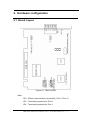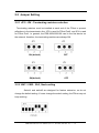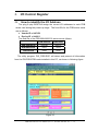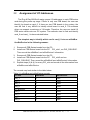
1
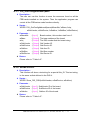
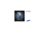
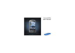
FRB-200U/200/100 User Manual Warranty All products manufactured by ICP DAS are warranted against defective materials for a period of one year from the date of delivery to the original purchaser. Warning ICP DAS assumes no liability for damages consequent to the use of this product. ICP DAS reserves the right to change this manual at any time without notice. The information furnished by ICP DAS is believed to be accurate and reliable. However, no responsibility is assumed by ICP DAS for its use, not for any infringements of patents or other rights of third parties resulting from its use. Copyright Copyright 2004 by ICP DAS. All rights are reserved. Trademark The names used for identification only may be registered trademarks of their respective companies. Tables of Contents 1. INTRODUCTION ...........................................................................................................................3 1.1 FEATURES .............................................................................................................................................. 6 1.2 SPECIFICATIONS .................................................................................................................................... 7 1.3 ORDERING INFORMATION ...................................................................................................................... 7 1.3.1 Options ........................................................................................................................................ 7 1.4 PRODUCT CHECK LIST ........................................................................................................................... 8 2. HARDWARE CONFIGURATION.................................................................................................9 2.1 BOARD LAYOUT .................................................................................................................................... 9 2.2 JUMPER SETTING ................................................................................................................................. 10 2.2.1 JP3 / JP4 : Terminating resistors selection............................................................................... 10 2.2.2 SW1 / SW2 : CLK, Node setting ................................................................................................ 10 2.3 PIN ASSIGNMENT.................................................................................................................................. 11 3. I/O CONTROL REGISTER .........................................................................................................12 3.1 HOW TO IDENTIFY THE I/O ADDRESS ................................................................................................... 12 3.2 ASSIGNMENT OF I/O ADDRESSES ......................................................................................................... 13 4. FRNET APPLICATION STRUCTURE........................................................................................15 5. SOFTWARE INSTALLATION ....................................................................................................17 5.1 SOFTWARE INSTALLING PROCEDURE................................................................................................... 17 5.2 PNP DRIVER INSTALLATION ................................................................................................................ 17 6. DLL FUNCTION DESCRIPTION ................................................................................................18 6.1 TABLE OF ERRORCODES AND ERRORSTRINGS..................................................................................... 18 6.2 FUNCTION DESCRIPTIONS .................................................................................................................... 19 6.3 DRIVER RELATIVE FUNCTIONS ............................................................................................................ 20 6.3.1 FRB_DriverInit.......................................................................................................................... 20 6.3.2 FRB_ActiveBoard...................................................................................................................... 20 6.3.3 FRB_GetDllVersion .................................................................................................................. 21 6.3.4 FRB_GetDriverVersion ............................................................................................................. 21 6.3.5 FRB_DriverClose ...................................................................................................................... 21 6.4 I/O FUNCTIONS................................................................................................................................ 22 6.4.1 FRB_SendSA ............................................................................................................................. 22 6.4.2 FRB_ ReceiveRA ....................................................................................................................... 22 6.4.3 FRB_ ReadRAStatus.................................................................................................................. 23 6.5 PROGRAM ARCHITECTURE .................................................................................................................. 24 FRB-200U/200/100 User Manual (Ver.1.3, Jun.2008, fmh-001-12) -----1 7. DEMO PROGRAMS FOR WINDOWS .......................................................................................25 7.1 DEMO1: SA AND RA FUNCTIONS FOR FRB-200/100 ......................................................................... 26 APPENDIX A. ...................................................................................................................................27 A.1 THE I/O ADDRESS MAP ....................................................................................................................... 27 A.1.1 RESET\ Control Register ............................................................................................................ 28 A.1.2 AUX Control Register................................................................................................................. 28 A1.3 Port Select Register ..................................................................................................................... 29 A.1.4 I/O Data Register........................................................................................................................ 30 A.2 WHERE THE RELATED SOFTWARE IS .................................................................................................... 31 A.3 DOS LIB FUNCTION............................................................................................................................ 32 FRB-200U/200/100 User Manual (Ver.1.3, Jun.2008, fmh-001-12) -----2 1. Introduction FRnet is a two-wire serial communication bus, wired in a similar manner to an RS-485. FRnet device connection is achieved using a multi-drop method. Unlike most communication methods based on RS-485, this new method does not use the traditional question/answer approach. Instead, it uses a fixed scan time to actively transmit data. Since there is no need for a CPU to process a communication protocol, FRnet can achieve high-speed data transmission in an isochronous manner. The FRB-200/100 is an isolated FRnet communication card designed for use in the host computer with a PCI bus, the FRB-200U only support the Universal PCI bus. The FRB-100 card has one FRnet port whereas the FRB-200U/200 card has two FRnet ports. Each FRnet port has 8 sender nodes and 8 receiver nodes. That is, the node address setting is defined as SA0~SA7 and RA8~RA15. Each node contains 16-bit data, which can be either a DI or DO type depending on what module you use. Therefore, it can control up to a maximum of 128(16X8) digital output channels and 128(16X8) digital input channels with a total scan time of 2.88ms for 250kbps or 0.72ms for 1Mbps. I/O data transmission is controlled by the hardware mechanism of the FRnet control chip which was developed by ICPDAS. It was designed to provide for the deterministic high speed communication in a network. This communication mechanism is dominated by the token-stream, which is generated by the network manager (SA0). This is located in the FRnet and provides for fixed scan-time and I/O synchronization capability without the need of any special communication protocol. Furthermore, special anti-noise circuitry has also been considered and built into the FRnet control chip to ensure communication reliability. However, the effectiveness of the FRnet connection depends on and is then ensured when the correct hardware configurations for the sender address (SA) and receiver address (RA) on the host controller and the remote module in the network have been installed properly. In general, the operating principle is FRB-200U/200/100 User Manual (Ver.1.3, Jun.2008, fmh-001-12) -----3 structured by the strategy of delivering the 16-bit data from the specified sender address (SAn) to the corresponding receiver address (RAn) via the broadcasting method controlled by the token-stream of the network manger, SA0. Based on this algorithm, there are some general rules that need to be followed: (1) The sender address needs to be unique in order to avoid any communication collisions. (2) Each of FRnet needs one and only one network manger defined as SA0. It plays the important role of producing the token-stream in the network. (3) The baud rates of the controller and the remote module need to be the same as on the FRnet. (4) The communication method is controlled by delivering the data of the specified sender address (SA) to the corresponding receiver address in the sequence of token 0 to (N-1) cyclically, as depicted below. (5) Due to the broadcasting algorithm adopted, the receiver address is not required to be unique. Therefore, it is easy to build in data delivery from one node (16-bit data) to a multi-node. Figure 1.1 Token stream controlled by network manger, SA0 FRB-200U/200/100 User Manual (Ver.1.3, Jun.2008, fmh-001-12) -----4 Under the application of FRB-200U/200/100, the SA0 node will cyclically issue a token to activate the data transmission from SAn to RAn, where n is 0~15. That means that the node SAn reads the data from the host memory and sends it to the RAn node, which is on a remote module. However, the RAn node on the host will receive data coming from the SAn node on the remote module and then write it into the received data memory on the host. Therefore, user can easily control the network I/O module through reading and writing the specified memory located on the host computer. Figure 1.2 FRnet structure FRB-200U/200/100 User Manual (Ver.1.3, Jun.2008, fmh-001-12) -----5 1.1 Features The Token stream is used to activate data transmission from the specified SA node to the corresponding RA nodes. The Network Manager is defined as SA0. Each of FRnet must have SA0 because it issues the Token stream into the network. The Token stream is produced cyclically by the hardware system (SA0) at the fixed time interval, see Figure 1.1. Therefore, the FRnet system can provide both the isochronous and deterministic functionalities. It can provide data transmission from one node (16-bit) to a multi-node at the same time because FRnet uses the principle of delivering the data from the sender address to the receiver address. This means, the sender address must be unique, but the receiver address can be different or the same in the network. The FRnet system can be easily extended by adding new modules to the network according to the FRnet principle. Device Inter-communication: A single device can talk to other devices by setting appropriate SA and RA node configurations. Adopt Memory-mapping technology to control I/O nodes. No software overhead: all data transmissions are performed automatically via the FRnet control chips. Therefore, there is no need for the CPU or firmware to process transmission protocols. It only needs simple RS-485 wiring. OS (operation system) independent. FRB-200U/200/100 User Manual (Ver.1.3, Jun.2008, fmh-001-12) -----6 1.2 Specifications Table 1.1 Characteristics of the FRB-200U/200/100 FRB-200U/200/100 Transfer speed 250Kbps 1Mbps Scan time 2.88ms 0.72ms Max transfer length 400 m 100 m Table 1.2 I/O Address of FRB-200U/200/100 series FRB-200U/200 FRB-100 I/O Address for Port 0 SA [0] ~[7] , RA [8] ~ [15] SA [0] ~ [7] , RA [8] ~ [15] I/O Address for Port 1 SA [0] ~ [7] , RA [8] ~ [15] Not Available Note: SA: Sender Address of a node, RA: Receiver Address of a node. Table 1.3 PCI Bus of FRB-200U/200/100 series FRB-200U FRB-100/200 Universal PCI Bus PCI Bus (+5/+3.3V) PCI Bus General specifications: • Operation temperature: 0℃~+55℃ • Storage temperature: -20℃~+65℃ • Humidity: 0~90% • Dimensions: 120mm x 90mm • Power consumption: 5V@250mA 1.3 Ordering information • FRB-200U : 250Kbps (2 Ports: SA 0~7, RA 8~15) • FRB-200 : 250Kbps (2 Ports: SA 0~7, RA 8~15) • FRB-100 : 250Kbps (1 Port : SA 0~7, RA 8~15) 1.3.1 Options • FR-2057T: 16-channel Isolated Sink Digital Output Module • FR-2053T: 16-channel Isolated Sink Digital Input Module • FR-2057TA: 16-channel Isolated Source Digital Output Module. • FR-2057TW: 16-channel Sink Type Isolated High Current Output Module. • FR-2054T: 8-Channel Digital Output and 8-Channel Digital Input Module. • FR-2152T: 8-channel Isolated Digital Input with 12-pin Screw Terminal Connector. • FR-2156T: 8-channel Isolated Digital Output with 12- pin Screw Terminal Connector. FRB-200U/200/100 User Manual (Ver.1.3, Jun.2008, fmh-001-12) -----7 1.4 Product Check list In addition to this manual, this package should include the following items: • One FRB-200U/200/100 card • One ICPDAS CD • One copy of the release notes Before continuing, please read the release notes first. They contain the following important information. 1. 2. 3. 4. The location of the software driver and utility How to install the software and utility The location of the diagnostic program FAQ Attention! If any of these items are missing or damaged, contact the dealer from whom you purchased the product. Save all shipping materials and the carton in case you need to ship or store the product in the future. FRB-200U/200/100 User Manual (Ver.1.3, Jun.2008, fmh-001-12) -----8 2. Hardware configuration 2.1 Board Layout Figure 2.1 FRB-100/200 Note: TB1 : FRnet communication connection ( Port 0 / Port 1). JP3 : Terminating resistors for Port 0. JP4 : Terminating resistors for Port 1. FRB-200U/200/100 User Manual (Ver.1.3, Jun.2008, fmh-001-12) ---- 9 2.2 Jumper Setting 2.2.1 JP3 / JP4 : Terminating resistors selection Terminating resistors must be installed at each end of the FRnet to prevent reflections in the transmission line. JP3 is used for FRnet Port0, and JP4 is used for FRnet Port1. In general, the FRB-200U/200/100 card is the first device on the network; therefore, the terminating resistors are always ON. ON (default) OFF ON(default) OFF 2.2.2 SW1 / SW2 : CLK, Node setting Switch1 and switch2 are designed for feature extension, so do not change the default setting. If users change the switch setting, the FRnet may not keep working. FRB-200U/200/100 User Manual (Ver.1.3, Jun.2008, fmh-001-12) ---- 10 2.3 Pin Assignment The FRB-200U/200 card has two FRnet ports (similar to RS-485 ports), and the FRB-100 only has a single port. The definitions of the pins on the connectors for the FRnet ports are shown in the following Table. Table 2.1 TB1 : 5-pin header Pin Number Description 1 Port0_A 2 Port0_B 3 N.C 4 Port1_A (FRB-200U/200 only) 5 Port1_B (FRB-200U/200 only) FRB-200U/200/100 User Manual (Ver.1.3, Jun.2008, fmh-001-12) ---- 11 3. 3.1 I/O Control Register How to identify the I/O Address The plug & play BIOS will assign the correct I/O addresses to each FRB series card during the power-up stage. The fixed IDs for the FRB series cards are as follows: • Vendor ID = 0xE159 • Device ID = 0x0001 The Sub IDs of the FRB-200U/200/100 series are as follows: FRB-200/100 FRB-200U Sub-Vendor ID 0x5F80 0x5FFF Sub-Device ID 0x01 0x03 Sub-Aux ID 0x00 0x00 The utility program, PIO_PISO.EXE, will detect and present all information from the PIO/PISO/FRB cards installed in this PC, as shown in following figure. Figure 3.1 FRB-200U/200/100 User Manual (Ver.1.3, Jun.2008, fmh-001-12) ---- 12 Assignment of I/O Addresses 3.2 The Plug & Play BIOS will assign proper I/O addresses to each FRB series card during the power-up stage. If there is only one FRB board, the user can identify the board as card_0. If there are two FRB boards in the system, the user will find it very difficult to identify which board is card_0. The software driver can support a maximum of 16 boards. Therefore, the user can install 16 FRB series cards onto one PC system. The methods used to find and identify card_0 and card_1 is demonstrated below: The simplest way to identify which card is card_0 is to use wSlotBus & wSlotDevice in the following manner: 1. 2. Remove all FRB Series boards from the PC. Install one FRB Series board into the PC PCI_slot1, run PIO_PISO.EXE. 3. 4. Then record the wSlotBus1 and wSlotDevice1 information. Remove all FRB Series boards from the PC. Install one FRB Series board into the PC PCI_slot2 and run 5. PIO_PISO.EXE. Then record the wSlotBus2 and wSlotDevice2 information. Repeat steps (3) & (4) for every PCI_slot and record all the information from wSlotBus and wSlotDevice. The records may look similar to the table below: Table 3.1 wSlotBus and wSlotDevice records PCI slot wSlotBus wSlotDevice Slot_1 0 0x07 Slot_2 0 0x08 Slot_3 0 0x09 Slot_4 0 0x0A Slot_5 1 0x0A Slot_6 1 0x08 Slot_7 1 0x09 Slot_8 1 0x07 PCI-BRIDGE FRB-200U/200/100 User Manual (Ver.1.3, Jun.2008, fmh-001-12) ---- 13 The above procedure will record all the wSlotBus and wSlotDevice information on a PC. These values will be mapped to this PC physical slots. The mapping will not be changed for any FRB card. Therefore, this information can be used to identify the specified FRB card by following these next 3 steps: Step1: Using the wSlotBus and wSlotDevice information in table 3-1 Step2: Input the board number into funtion GetConfigAddressSpace(…) to get the specified card information, especially the wSlotBus and wSlotDevice information. Step3: The user can identify a specified FRB card by comparing it to the data from the wSlotBus & wSlotDevice found in step1 and step2. Note that normally the card installed nearest to the CPU is card0 for FRB series cards. FRB-200U/200/100 User Manual (Ver.1.3, Jun.2008, fmh-001-12) ---- 14 4. FRnet Application Structure Figure 4.1 Note: (1) Refer to the “FRnet distributed I/O module manual” for details regarding the settings of the DSW (dipswitch). (2) The high-speed FRB cards can only work together with high-speed remote modules. Similarly, normal speed FRB cards can only work with normal speed remote modules. (3) The cabling method is similar to that used with the RS-485 networks. For long distance usage, a shielded twisted pair cable is required. FRB-200U/200/100 User Manual (Ver.1.3, Jun.2008, fmh-001-12) ---- 15 Figure 4.2 Note: (1) The MagicWire series enables PLCs to talk to each other via DIO ports. (2) MA11/12/21/22 supports A and Q type PLCs for Mitsubishi. FRB-200U/200/100 User Manual (Ver.1.3, Jun.2008, fmh-001-12) ---- 16 5. Software Installation The FRB-200U/200/100 can be used in DOS and Windows 98/Me/NT/2000/XP. For Windows O.S, the recommended installation steps are given in Sec 5.1 ~ 5.2 5.1 Software Installing Procedure Step 1: Insert the companion CD into the CD-ROM driver and wait a few seconds until the installation program starts automatically. If it does not start automatically for some reason, then please double-click the file 8000\NAPDOS\AUTO32.EXE on the CD. Step 2: Click the item: Install Toolkits (Software) / Manuals. Step 3: Click the item: FRnet Series Toolkits. Step 4: Click the item: FRnet PCI Cards. Step 5: Click FRB-200U/200/100. Step 6: Click “install Toolkit for Windows 98(or NT, 2K/XP)”. Then, the InstallShield will start the driver installation process to copy the related material to the indicated directory and register the driver on your computer. The driver target directory is as below for different systems. Windows NT/2000/XP : The FRB.dll will be copied onto c:\winnt\system32 The Napwnt.sys and FRB.sys will be copied into c:\winnt\system32\drivers Windows 95/98/Me : The FRB.DLL,and FRB.Vxd will be copied onto c:\windows\system 5.2 PnP Driver Installation After installing the hardware (FRB-200U/200/100) and you turn the power on for your PC, Windows 98/Me/2000/XP will find a PCI card device and then ask the user to provide FRB.inf to install the hardware driver onto the computer. If the user has trouble in procedure through this process, please refer to PnPinstall.pdf for more information. FRB-200U/200/100 User Manual (Ver.1.3, Jun.2008, fmh-001-12) ---- 17 6. DLL Function Description The DLL driver is the collection of function calls on the FRB- 200U/200/100 card for the Windows 98/Me/NT/2000/XP system. The application structure is presented in the following figure. The user application program was developed by designated tools such as VB, Delphi, VC, Borland C++ Builder, C#.NET and VB.NET which can call on the FRB.DLL driver in the user mode. Following that, the DLL driver will call up FRB.sys to access the hardware system. Figure 6.1 6.1 Table of ErrorCodes and ErrorStrings Table 6.1 ErrorCodes and ErrorStrings Error Error ID Code Error String 0 FRB_NoError OK ( No error !) 1 FRB _DriverOpenError 2 FRB _DriverNoOpen Device driver cannot be opened Users have to call the DriverInit function first 3 FRB _GetDriverVersionError 4 FRB _FindBoardError Cannot find board 5 FRB _ExceedBoardNumber Invalidate board number (Valid range: 0 to TotalBoards -1) 6 FRB_InputParameterError Get driver version error Input parameter error. FRB-200U/200/100 User Manual (Ver.1.3, Jun.2008, fmh-001-12) ---- 18 6.2 Function Descriptions All of the functions provided for the FRB-200U/200/100 are listed below with more detailed information for every function presented in the following section. However, in order to make their descriptions simpler and clearer, the attributes for the input and output parameters of the functions are indicated as [input] and [output] respectively, as shown in following table. Table 6.2 The attributes for the input and output parameters Keyword Setting parameter by user before calling this function ? Get the data/value from this parameter after calling this function ? [Input] Yes No [Output] No Yes [Input, Output] Yes Yes Table 6.3 Function definition Return Function Definition Type WORD FRB_DriverInit(WORD *wTotalBoard) WORD FRB_GetDllVersion(void) WORD FRB_GetDriverVersion(WORD *wDriverVersion) WORD FRB_SendSA(WORD wPort, WORD wSAn, WORD OutputData) WORD FRB_ReceiveRA(WORD wPort, WORD wRAn, WORD *wInputData) WORD FRB_ReadRAStatus(WORD wPort, BYTE *bRAStatus) void FRB_DriverClose(void) FRB-200U/200/100 User Manual (Ver.1.3, Jun.2008, fmh-001-12) ---- 19 6.3 Driver Relative Functions 6.3.1 • • • • 6.3.2 • • • • FRB_DriverInit Description : This subroutine will open the FRB driver and allocate the computer resource for the device. Furthermore, it will obtain all the FRB200U/200/100 boards installed in the system. This function must be used before applying other FRB functions. Syntax : WORD FRB_DriverInit(WORD * wTotalBoard); Parameter : wTotalBoard : [Output] Total FRB-200U/200/100 boards. Return: Please refer to "Section 6.1 Error Code". FRB_ActiveBoard Description : This subroutine will activate one of the FRB-200U/200/100 boards installed in the system. This function must be applied once before the I/O functions are used. Syntax : WORD FRB_ActiveBoard (WORD wBoardNo); Parameter : wBoardNo: [Input] Board number that you want to active, start from number 0(0Æthe First FRB Board,1Æthe Second FRB Board). Return: Please refer to "Section 6.1 Error Code". FRB-200U/200/100 User Manual (Ver.1.3, Jun.2008, fmh-001-12) ---- 20 6.3.3 • • • • 6.3.4 • • • • 6.3.5 • • • • FRB_GetDllVersion Description: This subroutine will obtain the version number of the FRB.DLL driver Syntax: WORD FRB_GetDllVersion(void) Parameter: None Return: 100(hex) for version 1.00 FRB_GetDriverVersion Description : This subroutine will obtain the version number information from the FRB driver. Syntax : WORD FRB_GetDriverVersion(WORD *wDriverVersion); Parameter : wDriverVersion : [Output] The version number of FRB driver. Return: Please refer to "Section 6.1 Error Code". FRB_DriverClose Description : This subroutine will close the FRB Driver and release this resource from the computers device resources. This function must be used once before exiting the user's application. Syntax : void FRB_DriverClose(void); Parameter : None Return: None FRB-200U/200/100 User Manual (Ver.1.3, Jun.2008, fmh-001-12) ---- 21 I/O FUNCTIONS 6.4 6.4.1 • • • FRB_SendSA Description : This subroutine will write the 16 bits of data into the FRB-200U/200/100 SAn, then SAn will send the data to the remote RAn. Syntax : WORD FRB_SendSA(WORD wPort, WORD wSAn, WORD wOutputData); Parameter : wPort : [Input] Port number (0ÆPort 0, 1ÆPort 1) wSAn : [Input] SA0 ~ SA7 (0ÆSA0,……,7ÆSA7) wOutputData : [Input] 16 bits data send to remote RAn from FRB-100/200 SAn. • 6.4.2 • • • • Return: Please refer to "Section 6.1 Error Code". FRB_ ReceiveRA Description : This subroutine will receive the 16 bits of data sent from remote SAn to the FRB-200U/200/100 RAn. Syntax : WORD FRB_ReceiveRA(WORD wPort, WORD wRAn, WORD *wInputData) Parameter : wPort :[Input] Port number. (0ÆPort 0, 1ÆPort 1) wRAn :[Input] RA8 ~ RA15. (8ÆRA8,……,15ÆRA15) wInputData :[Output] 16 bits data sent from remote SAn to FRB-100/200 RAn. Return: Please refer to "Section 6.1 Error Code". FRB-200U/200/100 User Manual (Ver.1.3, Jun.2008, fmh-001-12) ---- 22 6.4.3 • • • FRB_ ReadRAStatus Description : This subroutine will find out what the communication status of the remote SAn to the FRB-200U/200/100 RAn is, where n=8~15. Before the RA8-15 receiving data sent from remote SAn, the user can call this function to get the communication status of node 8~15. Syntax : WORD FRB_ReadRAStatus(WORD wPort, BYTE *bRAStatus) Parameter : wPort : [ Input ] Port number. (0ÆPort 0, 1ÆPort 1) bRAStatus : [Output] Communication status of Remote SAn to FRB-100/200/200U RAn, where n=8~15. bRAStatus : Bit 7 Bit 6 Bit 5 Bit 4 Bit 3 Bit 2 Bit 1 Node 15 Node 14 Node 13 Node 12 Node 11 Node 10 Node 9 Bit 0 Node 8 Node n=0: Communication of Remote SAn to FRB-200U/200/100 RAn is not active. Node n=1: Communication of Remote SAn to FRB-200U/200/100 RAn is active. • Return: Please refer to "Section 6.1 Error Code". FRB-200U/200/100 User Manual (Ver.1.3, Jun.2008, fmh-001-12) ---- 23 6.5 Program Architecture Figure 6.2 FRB-200U/200/100 User Manual (Ver.1.3, Jun.2008, fmh-001-12) ---- 24 7. Demo Programs for Windows All demo programs will not work properly if the DLL driver has not been installed correctly. During the DLL driver installation process, the installshields will register the correct kernel driver to the operation system and copy the DLL driver and demo programs to the correct position based on the driver software package you have selected (Win98,Me,NT,win2000,XP). Once the driver installation is complete, the related demo programs and development library and the declaration header files for the different development environments will be presented as follows. |--\Demo |--\DLL_BCB4_XXXXXX.exe Æ demo program Æ for Borland C++ Builder 4 |--\DLL_Delphi4_XXXXXX.exe Æ for Delphi 4 |--\DLL_VB6_XXXXXX.exe Æ for Visual Basic 6 |--\DLL_VC6_XXXXXX.exe Æ for Visual C++ 6 |--\DLL_CSharp2005_XXXXXX.exe Æ for C#.NET 2005 |--\DLL_VBnet2005_XXXXXX.exe Æ for VB.NET 2005 The list of demo programs : Demo1 : SA and RA functions for FRB-200U/200/100 FRB-200U/200/100 User Manual (Ver.1.3, Jun.2008, fmh-001-12) ---- 25 7.1 DEMO1: SA and RA functions for FRB-200/100 Step 1: Connect the FR-2053 and the FR-2057(Refer to figure 7.1). Step 2: Set the FR-2053 address to SA8 and the FR-2057 address to RA0. Step 3: Click the SAn (Digital Output) check box to send the 16-bit data from the host SA0 (FRB-200U/200/100) to remote RA0 (FR-2057). Step 4 : On the screen of Fig7.2, the RAn ( Digital Input ) status will display the 16-bit data sent from the remote SA8 (FR-2053) to the host RA8 (FRB-200U/200/100). Figure 7.1 Figure 7.2 FRB-200U/200/100 User Manual (Ver.1.3, Jun.2008, fmh-001-12) ---- 26 Appendix A. A.1 The I/O Address Map The I/O address for the FRB series cards are automatically assigned by the main board ROM BIOS. The I/O address can also be re-assigned by the user. It is strongly recommended that users do not change the I/O address. The Plug & Play BIOS will effectively perform the assignment of proper I/O addresses to each FRB series card. The I/O addresses for the FRB are given in the table below, all of which are based on the base address of each card. Table A.1 FRB-200U/200/100 board addresses: ADDRESS READ WRITE wBase+0 RESET\ control register Same wBase+2 Aux control register Same wBase+3 Port select register Same wBase+0xc0 RA8 (Low byte)/Node8-15 Status SA0 (Low byte) wBase+0xc4 RA8 (High byte) SA0 (High byte) wBase+0xc8 RA9 (Low byte) SA1 (Low byte) wbase+0xcc RA9 (High byte) SA1 (High byte) wBase+0xd0 RA10 (Low byte) SA2 (Low byte) wBase+0xd4 RA10 (High byte) SA2 (High byte) wBase+0xd8 RA11 (Low byte) SA3 (Low byte) wBase+0xdc RA11 (High byte) SA3 (High byte) wBase+0xe0 RA12 (Low byte) SA4 (Low byte) wBase+0xe4 RA12 (High byte) SA4 (High byte) wBase+0xe8 RA13 (Low byte) SA5 (Low byte) wbase+0xec RA13 (High byte) SA5 (High byte) wBase+0xf0 RA14 (Low byte) SA6 (Low byte) wBase+0xf4 RA14 (High byte) SA6 (High byte) wBase+0xf8 RA15 (Low byte) SA7 (Low byte) wBase+0xfc RA15 (High byte) SA7 (High byte) FRB-200U/200/100 User Manual (Ver.1.3, Jun.2008, fmh-001-12) ---- 27 A.1.1 RESET\ Control Register (Read/Write): wBase+0 Bit 7 Bit 6 Bit 5 Bit 4 Bit 3 Bit 2 Bit 1 Bit 0 Reserved Reserved Reserved Reserved Reserved Reserved Reserved RESET\ When the PC power is first turned on, the RESET\ signal is in a Lowstate. This will disable all D/I/O operations (FRnet will not be functioning). The user has to set the RESET\ signal to a High-state before any D/I/O command applications are initiated. // RESET\ = 1 Æ The LED indicator is flashing // Æ Enables the DI/DO operations // RESET\ = 0 Æ The LED indicator is off outportb(wBase,1); outportb(wBase,0); Æ Disables the DI/DO operations // A.1.2 AUX Control Register (Read/Write): wBase+2 Bit 7 Bit 6 Bit 5 Bit 4 Bit 3 Bit 2 Bit 1 Bit 0 Aux 7 Aux 6 Aux 5 Aux 4 Aux 3 Aux 2 Aux 1 Aux 0 Aux n=0Æ this Aux is used as a D/I Aux n=1Æ this Aux is used as a D/O Note: n=0~7 When the PC is first turned on, all Aux signals are in a Low-state. This means that all Aux controls are enabled as DI. Please set all the Aux states to DO. FRB-200U/200/100 User Manual (Ver.1.3, Jun.2008, fmh-001-12) ---- 28 A1.3 Port Select Register (Read/Write): wBase+3 Bit 7 Bit 6 Bit 5 Bit 4 Bit 3 Bit 2 Bit 1 Bit 0 1 1 1 1 NS1 Port1 NS0 Port0 Port0=0 Æ Select FRB-200U/200/100 Port 0. Port0=1 Æ Deselect FRB-200U/200/100 Port 0 outportb(wBase+0x03,0xfe); // Select Port 0, disable node status outportb(wBase+0xc0, LSB); // Send the Low byte to SA0 data=inportb(wBase+0xc0); // Receive the Low byte from RA8 Port1=0 Æ Select FRB-200U/200/100 Port 1. Port1=1 Æ Deselect FRB-200U/200/100 Port 1 outportb(wBase+0x03,0xfb); // Select Port 1, disable node status outportb(wBase+0xc0, LSB); // Send the Low byte to SA0 data=inportb(wBase+0xc0); // Receive the Low byte from RA8 NS0=0 Æ Enable Port0 node status. NS0=1 Æ Disable Port0 node status. outportb(wBase+0x03,0xfd); // Enable Port0 node status bStatus=inportb(wBase+0xc0); // Receive node 8-15 status of Port0 NS1=0 Æ Enable Port1 node status. NS1=1 Æ Disable Port1 node status. outportb(wBase+0x03,0xf7); // Enable Port1 node status bStatus=inportb(wBase+0xc0); // Receive node 8-15 status of Port1 bStatus : Bit 7 Bit 6 Bit 5 Bit 4 Bit 3 Bit 2 Bit 1 Node 15 Node 14 Node 13 Node 12 Node 11 Node 10 Node 9 Bit 0 Node 8 Node n=0: Communication of Remote SAn to FRB Series RAn is not active. Node n=1: Communication of Remote SAn to FRB Series RAn is active. note : n= 8~15 FRB-200U/200/100 User Manual (Ver.1.3, Jun.2008, fmh-001-12) ---- 29 A.1.4 I/O Data Register (Read/Write): wBase+0xc0/c4/c8/cc/d0/d4/d8/dc/e0/e4/e8/ec/f0/f4/f8/fc Bit 7 Bit 6 Bit 5 Bit 4 Bit 3 Bit 2 Bit 1 Bit 0 D7 D6 D5 D4 D3 D2 D1 D0 outportb(wBase+0xc0, LSB); outportb(wBase+0xc4, MSB); // Send the Low byte to SA0 // Send the High byte to SA0 ……. outportb(wBase+0xf8, LSB); outportb(wBase+0xfc, MSB); // Send the Low byte to SA7 // Send the High byte to SA7 A convenient addressing calculation for SAn is offset_LSB = wBase + 0xc0 + n*8, and offset_ MSB=offset_LSB+4, where n<=7. Using SA7 as an example, offset_LSB = wBase+ 0xc0+7*8, or = wBase+0xf8; and offset_MSB= wBase+0xfc. (*Note 1 ) data=inportb(wBase+0xc0); data=inportb(wBase+0xc4); // Receive the Low byte from RA8 // Receive the High byte from RA8 ……. data=inportb(wBase+0xf8); data=inportb(wBase+0xfc); // Receive the Low byte from RA15 // Receive the High byte from RA15 A convenient addressing calculation for RAn is offset_LSB = wBase + 0xc0 + (n8)*8, and offset_ MSB=offset_LSB+4, where n>=8. Using RA15 as an example, offset_LSB = wBase + 0xc0 +(15-8) *8, or = wBase+0xf8; and offset_MSB= wBase+0xfc. Note 1: Before receiving the RA0 low byte data(wBase+0xc0), users must disable the node status(Bit-1/Bit-3 of wBase+3 address). If users enable the node status, they will get a node 8-15 status instead of the RA8 low byte data via reading the wBase+0xc0 address. FRB-200U/200/100 User Manual (Ver.1.3, Jun.2008, fmh-001-12) ---- 30 A.2 Where the related software is The related DOS software and demos in the CD are given as follows: • • • \TC\*.* \MSC\*.* \BC\*.* Æ for Turbo C 2.xx or above Æ for MSC 5.xx or above Æ for BC 3.xx or above • \TC\LIB\*.* Æ for TC library • • \TC\DEMO\*.* \TC\DIAG\*.* Æ for TC demo program Æ for TC diagnostic program • • • \TC\LIB\PIO.H \TC\\LIB\TCPIO_L.LIB \TC\\LIB\TCPIO_H.LIB Æ TC declaration file Æ TC large model library file Æ TC huge model library file • • • \MSC\LIB\PIO.H \MSC\LIB\MSCPIO_L.LIB \MSC\\LIB\MSCPIO_H.LIB Æ MSC declaration file Æ MSC large model library file Æ MSC huge model library file • • • \BC\LIB\PIO.H \BC\LIB\BCPIO_L.LIB \BC\\LIB\BCPIO_H.LIB Æ BC declaration file Æ BC large model library file Æ BC huge model library file The list of demo programs : DEMO1 : Digital Output function of FRB-200U/200 DEMO2 : Digital Input/Output function of FRB-200U/200/100 DEMO3 : Check node status of FRB-200U/200/100 RA8 to 15. FRB-200U/200/100 User Manual (Ver.1.3, Jun.2008, fmh-001-12) ---- 31 A.3 DOS LIB Function A.3.1 Table of ErrorCode and ErrorString Error Code Error ID Error String 0 NoError OK ! No Error! 1 DriverHandleError Device driver opened error 2 DriverCallError Got the error while calling the driver functions 3 FindBoardError Can't find the board on the system 4 TimeOut Timeout 5 ExceedBoardNumber Invalid board number (Valid range: 0 to TotalBoards -1) 6 NotFoundBoard Can't detect the board on the system Table A.2 ErrorCode and ErrorString The following functions are provided: 1. PIO_DriverInit(&wBoard, wSubVendor, wSubDevice, wSubAux) 2. PIO_GetConfigAddressSpace(wBoardNo,*wBase,*wIrq, *wSubVendor, *wSubDevice, *wSubAux, *wSlotBus, *wSlotDevice) 3. ShowPIOPISO(wSubVendor, wSubDevice, wSubAux) A.3.2 PIO_DriverInit • • • • Description : This function can detect all the FRB series cards in the system. It is implemented based on the PCI Plug & Play mechanism-1. It will find all the FRB series cards installed in this system and save all their resources into the library. Syntax : WORD PIO_DriverInit(WORD *wBoards, WORD wSubVendorID, WORD wSubDeviceID,WORD wSubAuxID) Parameter : WBoards wSubVendor wSubDevice wSubAux : [Output] Number of boards found in this PC : [Input] SubVendor ID of the board : [Input] SubDevice ID of the board : [Input] SubAux ID of the board Return: Please refer to " Table A.2". FRB-200U/200/100 User Manual (Ver.1.3, Jun.2008, fmh-001-12) ---- 32 A.3.3 PIO_GetConfigAddressSpace • • • • Description : The user can use this function to save the resources found on all the FRB cards installed on the system. Then the application program can control all the FRB series cards functions directly. Syntax : WORD PIO_GetConfigAddressSpace(wBoardNo,*wBase,*wIrq, wSubVendor, wSubDevice,*wSubAux,*wSlotBus,*wSlotDevice) Parameter : wBoardNo wBase wIrq wSubVendor wSubDevice : [Input] : [Output] : [Output] : [Output] : [Output] wSubAux wSlotBus wSlotDevice : [Output] Sub Aux ID. : [Output] Slot Bus number. : [Output] Slot Device ID. Board number, this number start from 0. The base address of the board The IRQ number that the board using. Sub Vendor ID. Sub Device ID. Return: Please refer to " Table A.2". A.3.4 ShowPIOPISO • • • • Description : This function will show a text string for a special Sub_ID. This text string is the same as that defined in the PIO.H. Syntax : WORD Show_PIO_PISO(wSubVendor, wSubDevice, wSubAux) Parameter : wSubVendor : [Input] SubVendor ID of the board wSubDevice : [Input] SubDevice ID of the board wSubAux : [Input] SubAux ID of the board. Return: Please refer to " Table A.2". FRB-200U/200/100 User Manual (Ver.1.3, Jun.2008, fmh-001-12) ---- 33