1
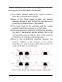
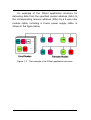
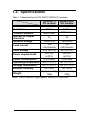
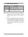
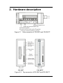
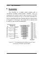
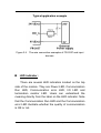
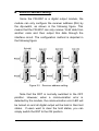
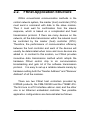
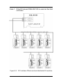
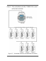
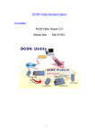
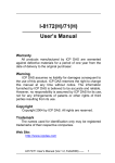
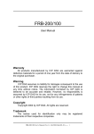
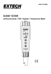
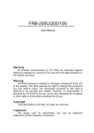
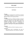
FR-2057
A 16 DO channels Module for the FRnet system
User Manual
Warranty
All products manufactured by ICP DAS are warranted
against defective materials for a period of one year from
the date of delivery to the original purchaser.
Warning
ICPDAS assumes no liability for damages consequent
to the use of this product. ICP DAS reserves the right to
change this manual at any time without notice. The
information furnished by ICP DAS is believed to be
accurate and reliable. However, no responsibility is
assumed by ICP DAS for its use, not for any infringements
of patents or other rights of third parties resulting from its
use.
Copyright
Copyright 2004 by ICP DAS. All rights are reserved.
Trademark
The names used for identification only may be
registered trademarks of their respective companies.
FR-2057 User Manual (Ver 1.0 , Oct/2004 ) ------
1
Table of Contents
1. Introduction ..................................................... 3
1.1. Features................................................................ 6
1.2. Specifications........................................................ 7
1.3. Ordering information ............................................ 8
2. Hardware description ..................................... 9
2.1. Pin Assignment ................................................... 10
2.1.1.
Side connector ..................................................... 10
2.1.2.
Top connector .......................................................11
2.2. FRnet Application Structure ............................... 14
FR-2057 User Manual (Ver 1.0 , Oct/2004 ) ------
2
1. Introduction
The FR-2057/2057T module provides a 16-channel
isolated photo-coupler digital output in the FRnet. The “-T”
denotes the screw terminal connector, allowing users to
connect to the DO signals on module directly. The I/O data
transmission is controlled by the FRnet control chip which
was developed by ICPDAS. It was designed to provide for a
deterministic high speed network communication. The
communication mechanism is dominated by the
token-stream, which is generated by the network manager
located at a specific node (SA0). This manager provides for
fixed scan-time and I/O synchronization capability without
the need of any special communication protocol.
Furthermore, special anti-noise circuitry has also been
considered and built into the FRnet control chip to ensure
communication reliability. This distributive digital output
module must be connected to other module or a host
controller with a network manger built in.
However, the effectiveness of the FRnet connection
depends on and is then ensured when the correct hardware
configurations for the sender address (SA) and receiver
address (RA) on the host controller and the remote module
in the network have been installed properly. In general, the
operating principle is structured by the strategy of delivering
the 16-bit data from the specified sender address (SAn) to
the corresponding receiver address (RAn) via the
broadcasting method controlled by the token-stream of the
FR-2057 User Manual (Ver 1.0 ) ------ 3
network manager, SA0. Based on this algorithm, there are
some general rules that need to be followed:
(1) The sender address needs to be unique in order to
avoid any communication collisions.
(2) Each of the FRnet needs at least one network
manager defined as SA0. It plays the important role of
producing the token-stream in the network.
(3) The baud rates of the controller and the remote
modules need to be the same as on the FRnet.
(4) The communication method is controlled by delivering
the data of the specified sender address (SA) to the
corresponding receiver address (RA) in the sequence
of token 0 to N cyclically, as depicted below.
(5) Due to the broadcasting algorithm adopted, the
receiver address is not required to be unique.
Therefore, it is easy to build a data delivery from one
node (16-bit data) to a multi-node.
Figure 1.1 Token stream controlled by network manager, SA0
FR-2057 User Manual (Ver 1.0 ) ------ 4
An example of the FRnet application structure for
delivering data from the specified sender address (SAn) to
the corresponding receiver address (RAn) by a 4-wire inter
module cable, including a 2-wire power supply cable, is
shown in the figure below.
Figure 1.2
The example of an FRnet application structure
FR-2057 User Manual (Ver 1.0 , Oct/2004 ) ------
5
1.1.
Features
The Token stream is used to activate data transmission
from the specified SA node to the corresponding RA
nodes.
The Network Manager is defined as SA0. Each of the
FRnet must have SA0 because it issues the Token stream
into the network.
The Token stream is produced cyclically by the hardware
system (SA0) at the fixed time interval, see Figure 1.1.
Therefore, the FRnet system can provide for both
Isochronous and Deterministic functionalities.
It can provide data transmission from one node (16-bit) to
one node or from one node to multiple nodes at the same
time because FRnet uses the principle of delivering the
data from the sender address to the receiver address.
Therefore, the sender address must be unique, but the
receiver address can be different or the same in the
network.
The FRnet system can easily be extended by adding new
modules to the network according to the FRnet principle.
Device Inter-communication: A single device can talk to
other devices by setting appropriate SA and RA node
configurations.
No software overhead: All data transmissions are
performed automatically via the FRnet control chip.
Therefore, there is no need for the CPU or firmware to
process transmission protocols.
It only needs simple RS-485 wiring.
The DIN-Rail mounting is provided.
FR-2057 User Manual (Ver 1.0 , Oct/2004 ) ------
6
1.2. Specifications
Table 1.1 Specifications for FR-2057(T)/2057H(T) modules.
Transfer speed
Scan time
Transfer distance
Number of Output
channels
Isolation voltage
FR-2057(T)
DO module
250Kbps
2.88ms
400m max.
FR-2057H(T)
DO module
1Mbps
0.72ms
100m max.
16
16
1500Vrms
1500Vrms
100
100
Load current
mA/channel
mA/channel
Load voltage
24V (±10%)
24V (±10%)
24V DC
24V DC
Power requirements
(±10%)
(±10%)
Power consumption
2.0W Max
2.0W Max
Operating temperature -25°C~+70°C -25°C~+70°C
Storage temperature
-30°C~+70°C -30°C~+70°C
35~85%
35~85%
Relative humidity
Approximately Approximately
Weight
120g
120g
Note: The H version (high speed version) is optional.
FR-2057 User Manual (Ver 1.0 , Oct/2004 ) ------
7
1.3. Ordering information
Model No.
FR-2057(T)
Description
250Kbps RA 0,1,2,3,4,5,6,7
FR-2057H(T) 1Mbps
DN-20
RA 0,1,2,3,4,5,6,7
DIN-Rail Mountable I/O Connector Block
with two 20-pin Header connectors
Note: a) The T version module has terminal on the panel.
Therefore, users can connect their I/O to the
terminal directly without a DN-20 extension
board.
b) The H version (high speed version) is optional. It
is recommended to choose the normal speed
version first. Modules of different speed version
are not allowed to work together. If you need
high-speed version, please make contact with
manufacturer.
FR-2057 User Manual (Ver 1.0 , Oct/2004 ) ------
8
2. Hardware description
Figure 2.1
Side connector of FR-2057 and FR-2057T.
Figure 2.2
Top connector of FR-2057 and FR-2057T.
FR-2057 User Manual (Ver 1.0 , Oct/2004 ) ------
9
2.1. Pin Assignment
2.1.1. Side connector
Please refer to Figure 2.1. On the side of the
module, there is one connector, as shown in the following
figure. This connector provides the power and the
communication interface. Users need to connect the
DC24V power source and the FRnet cable through this
interface.
The following figure is a connector on the side of the
module providing the external DC Power for the module. It
is designed to be used as the power source of the I/O
connection interface.
0V
24V
In additional to these connectors, there is also one
switch on the side of the module which can decide to use
the internal terminal resistor on the network or not. If you
switch it on, it means that the module will provide the
terminal resistor on the network. Note that each network
needs two modules to be on, which are usually the first
and last module on the network.
FR-2057 User Manual (Ver 1.0 ) ------ 10
2.1.2. Top connector
I/O connectors :
The FR-2057 is a digital output module with a
16-channel isolated photo-coupler interface. The Pin
assignments and interface circuit of input connectors of FR-2057
and FR-2057T are shown in Fig. 2.3. The wire connection for
how to cooperate with the controlled device is also shown
in Figure2.4. In this figure, the resister R1 is optional and
is used for over-current consideration.
Figure 2.3
Pin assignments and interface circuit of input
connectors of FR-2057 and FR-2057T.
FR-2057 User Manual (Ver 1.0 ) ------ 11
Figure 2.4
The wire connection examples of FR-2057 and input
devices.
LED indicator :
There are several LED indicators located on the top
side of the module. They are Power LED, Communication
Run LED, Communication error LED, I/O LED and
termination resistor LED. Users can understand the
meaning directly from the label on the LED indicator. Note
that the Communication Run LED and the Communication
error LED illustrate whether the quality of communication
is OK or not.
FR-2057 User Manual (Ver 1.0 , Oct/2004 ) ------
12
Receiver address setting :
Since the FR-2057 is a digital output module, the
module can only configure the receiver address (RA) by
the dip-switch, as shown in the following figure. This
means that the FR-2057 can only receive 16-bit data from
another node and then output this data through the
interface circuit. The configuration method is depicted in
the following figure:
Figure 2.5
Receiver address setting.
Note that the RST is normally switched to the OFF
position. However, when a communication error is
detected by the module, the communication error LED will
be turned on and all digital output will be held in their last
states. If users want to clear the hold states, you can
simply switch the RST to the ON position.
FR-2057 User Manual (Ver 1.0 ) ------ 13
2.2.
FRnet Application Structure
Within conventional communication methods in the
control network system, the master (host) controller (CPU)
must send a command with data to the slave module.
Then it must wait for confirmation from the slave’s
response, which is based on a complicated and fixed
transmission protocol. If there are many devices on the
network, all the data transmission within the network must
be controlled by the master (host) controller (CPU).
Therefore, the performance of communication efficiency
between the host controller and each of the devices will
usually be deteriorated when more and more devices are
added in. In contrast to this solution, our FRnet provides
innovative data transmission method which adopts the
hardware FRnet control chip to do communication
broadcasting and gets rid of the software transmission
protocol. It is easy to set up a reliable network merely by
hardware setting both the "Sender Address" and "Receiver
Address" of all the modules.
There are two FRnet host controllers provided by
ICPDAS products, the FRB-100/200 and the 7188EF-016.
The first one is a PCI interface add-on card, and the other
one is an Ethernet embedded controller. Two possible
application configurations are demonstrated as follows.
FR-2057 User Manual (Ver 1.0 ) ------ 14
Case 1: If the PC-based FRB-200/100 is used as the host
controller.
Figure 2.6
PCI interface FRnet card and distributed IO modules
FR-2057 User Manual (Ver 1.0 , Oct/2004 ) ------
15
Case 2: If the embedded controller 7188EF-016 is used
as the host controller.
Figure 2.7
Embedded controller and distributed IO modules
FR-2057 User Manual (Ver 1.0 , Oct/2004 ) ------
16