1
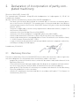
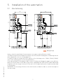
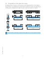
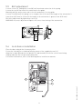
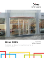
IP2135 EN
Ditec REXS
Technical manual
Sliding
doors automation
(Original instructions)
www.ditecentrematic.com
Index
Subject
Page
1.
General safety precautions
3
2.
Declaration of incorporation of partly completed machinery
4
Machinery directive
4
Technical data
5
Applications
5
4.
Standard installation
6
5.
Installation of the automation
7
5.1
Box fastening
7
5.2
Preparation of glass door wing
9
5.3
Door wing installation and adjustment
10
5.4
Floor guide installation
11
5.5
Belt adjustment
12
5.6
Lock installation
12
6.
Electrical connections
13
7.
Ordinary maintenance program
14
User instructions
15
General safety precautions
15
Manual release instruction
17
Function selector user instructions
18
2.1
3.
3.1
Key
This symbol indicates instructions or notes regarding safety, to which special attention must be paid.
This symbol indicates useful information for the correct functioning of the product.
IP2135EN - 2013-09-27
i
2
1. General safety precautions
IP2135EN - 2013-09-27
Failure to observe the information in this manual may result
in minor personal injury or damage to equipment.
Save these instructions for future reference.
This installation manual is intended for qualified personnel only.
Installation, electrical connections and adjustments must be performed in accordance with
Good Working Methods and in compliance with the present standards.
Read the instructions carefully before installing the product.
Bad installation could be dangerous.
The packaging materials (plastic, polystyrene, etc.) should not be discarded in the environment or left within reach of children, as these are a potential source of danger.
Before installing the product, make sure it is in perfect condition.
Do not install the product in explosive areas and atmospheres: the presence of inflammable
gas or fumes represents a serious safety hazard.
Before installing the motorisation device, make all the necessary structural modifications in
order to create safety clearance and to guard or isolate all the crushing, shearing, trapping
and general hazardous areas.
Make sure the existing structure is up to standard in terms of strength and stability.
The motorisation device manufacturer is not responsible for failure to observe Good Working
Methods when building the frames to be motorised or for any deformation during use.
The safety devices (photocells, safety edges, emergency stops, etc.) must be installed
taking into account: applicable laws and directives, Good Working Methods, installation
premises, system operating logic and the forces developed by the motorised door.
The safety devices must protect the crushing, cutting, trapping and general hazardous areas
of the motorised door.
Display the signs required by law to identify hazardous areas.
Each installation must bear a visible indication of the data identifying the motorised door.
When requested, connect the motorised door to an effective earthing system that complies
with current safety standards.
During installation, maintenance and repair operations, cut off the power supply before opening
the cover to access the electrical parts.
The automation protection casing must be removed by qualified personnel only.
The electronic parts must be handled using earthed antistatic conductive arms.
The manufacturer of the motorisation declines all responsibility in the event of component
parts being fitted that are not compatible with the safe and correct operation.
Use original spare parts only for repairs or replacements of products.
The installer must supply all information on automatic, manual and emergency operation of the
motorised door and must provide the user with the operating instructions.
3
2. Declaration of incorporation of partly completed machinery
(Directive 2006/42/EC, Annex II-B)
The manufacturer Entrematic Group AB with headquarters in Lodjursgatan 10, SE-261 44
Landskrona, Sweden
declares that the automation system for Ditec VALOR sliding doors:
-
has been constructed to be installed on a manual door to construct a machine pursuant to the Directive 2006/42/EC. The manufacturer of the motorized door shall declare
conformity pursuant to the Directive 2006/42/EC (annex II-A), prior to the machine being
put into service;
-
conforms to applicable essential safety requirements indicated in annex I, chapter 1 of
the Directive 2006/42/EC;
-
conforms to the Low Voltage Directive 2006/95/EC;
-
conforms to the Electromagnetic Compatibility Directive 2004/108/EC;
-
technical documentation conforms to Annex VII-B to the Directive 2006/42/EC;
-
technical documentation is managed by Marco Pietro Zini with offices in Via Mons. Banfi,
3 - 21042 Caronno Pertusella (VA) - ITALY;
-
a copy of technical documentation will be provided to national competent authorities,
following a suitably justified request.
Landskrona, 05-08-2013
Marco Pietro Zini
(President)
2.1 Machinery Directive
IP2135EN - 2013-09-27
Pursuant to Machinery Directive (2006/42/EC) the installer who motorizes a door or gate has
the same obligations as the manufacturer of machinery and as such must:
- prepare the technical file which must contain the documents indicated in Annex V of the
Machinery Directive;
(The technical file must be kept and placed at the disposal of competent national authorities for at least ten years from the date of manufacture of the motorized door);
- draw up the EC Declaration of Conformity in accordance with Annex II-A of the Machinery
Directive and deliver it to the customer;
- affix the EC marking on the motorized door in accordance with point 1.7.3 of Annex I of
the Machinery Directive.
4
3. Technical data
Ditec REXS
Power supply
230 V~ 50/60 Hz
Absorption
0,5 A
Power fuse
F1A
Rated power input
200 W
Max speed 1 wing
0,6 m/s
Max speed 2 wings
1,2 m/s
Service life
5 - HEAVY DUTY
Intermittence
S3=100%
Max door weight 1 wing
100 kg
Max door weight 2 wings
140 kg
Temperature
-20 °C - +55 °C
Temperature with batteries
-10 °C - +50 °C
Degree of protection
IP20
(FOR INTERNAL USE ONLY)
Control panel
EL20
Accessories power supply
24 V 0,5 A
3.1 Operating instructions
Service class: 5 (minimum 5 years of working life with 600 cycles per day).
Applications: VERY INTENSE (for shared entrances with very intense pedestrian use).
-
Performance characteristics are to be understood as referring to the recommended weight
(approx. 2/3 of maximum permissible weight). A reduction in performance is to be expected
when the access is made to operate at the maximum permissible weight.
Service class, running times, and the number of consecutive cycles are to be taken as merely
indicative having been statistically determined under average operating conditions, and are
therefore not necessarily applicable to specific conditions of use. During given time spans
product performance characteristics will be such as not to require any special maintenance.
The actual performance characteristics of each automatic access may be affected by independent variables such as friction, balancing and environmental factors, all of which may substantially alter the performance characteristics of the automatic access or curtail its working life
or parts thereof (including the automatic devices themselves). When setting up, specific local
conditions must be duly borne in mind and the installation adapted accordingly for ensuring
maximum durability and trouble-free operation.
-
IP2135EN - 2013-09-27
-
i
The given operating and performance features can only be guaranteed with the use of
Entrematic accessories and safety devices.
5
4. Standard installation
3
1
2
5
6
A
4
7
0
GND
12
8
10
9
Ref.
0
1
2
3
4
5
6
7
8
9
10
11
12
A
Code
Ditec REX S
EL20
AL15
REXAB
PAS024AMW (microwave+infrared), or
PASAA2 (only infrared)
PAS024AMW (microwave+infrared), or
PASAA2 (only infrared)
PASAT3
Description
Operator
Drive unit
Control panel
Transformer
Emergency batteries (optional)
No-break batteries (optional)
Combined sensor for opening and safety during closing
external side
Combined sensor for opening and safety during closing
internal side (operator)
Safety during opening sensor (outside or inside the operator’s housing)
Release handle
Functions selector switch
Photocells (NOT ACCORDING TO STANDARD EN 16005)
Display
Open push buttons
LOKSBM
COME - COMHK
CELPR
MD1 + MDA
PFP1 - PFP2
PDP1 - PDP2
Connect the power supply to an approved omnipolar switch with an opening distance of the contacts
of at least 3mm (not supplied). The connection to the mains must be made via an independent channel, separated from the connections to command and safety devices.
6
IP2135EN - 2013-09-27
11
5. Installation of the automation
5.1 Box fastening
100
190
65
160
190
65
160
55
55
100
REXAIC
REXAL
HM=H-28
50
10
10
max 50
2995
15
H
40
H
22
HM=H-32
19
22
18
P833
IP2135EN - 2013-09-27
Wiring passage
Unless otherwise specified, all measurements are expressed in millimetres (mm).
The REX automation wall fixing measurements are illustrated in the diagram, considering that the
door wing profiles are not of our production.
If the door wings are made with DITEC profiles of the following series: PAM16, PAM23, PAM45,
refer to the measurements in the related manuals.
Fix the box with M6 Ø12 steel plugs or 6MA. screws. Distribute the fixing points approx. every 800 mm.
Make sure that the box is level and its top surface is perpendicular with the floor and not deformed
lengthwise with the shape of the wall. If the wall is not straight and smooth, the box must be fixed
to metal plates.
WARNING: The fastening of the box to the wall must be suitable in order to sustain the weight of
the door wings.
7
IP2135EN - 2013-09-27
10
H
HVM=H-9
10÷12
10
H
AC1356
8
10÷12
HVM=H+1
30
10
11
1
190
65
160
190
160
55
100
100
REXAC
REXAIC
AC1356
47
Wiring passage
5.2 Preparation of the glass door wing
The diagram indicates the process measurements of the aluminium profile AC1356 and glass.
Ø10 through holes are required on the aluminium profile and Ø15 on the glass for fastening. The
number of holes and related distance between centres are based on the door wing width. Silicon
should ideally be used between the edge of the glass and the internal base of the profile.
100
Ø10
11
11
Ø10
100
100
100
100
100
100
100
100
Ø15
Ø15
L>1000
L≤1000
100
100
30
30
100
Ø10
Ø15
L>1000
L≤1000
10
100
100
100
100
Ø15
Ø15
100
30
30
100
Ø15
L≤1000
L>1000
12
With AC4255 or AC4870 glass wing attachment applications, see the respective manual.
IP2135EN - 2013-09-27
i
9
5.3 Wings installation and adjustment
b
c
b
a
a
Fix the door wing to the carriage with screws [a].
The outer wheel of the carriage must not protrude
beyond the dimension of the door wing.
Adjust the horizontal position of the door wing in
accordance with the measurements indicated in
diagram REX 2 for 2 door wing automations, REX
1 RH for right-hand opening automations and REX
1 LH for left-hand opening automations. Secure
the adjustment with screws [a].
Loosen screws [b], adjust the vertical position of
the door wing by means of screw [c] and fix the
adjustment with screws [b].
Check, by moving the door manually, that the
movement is free and without friction and that
al the wheels rest on the guide.
WARNING: Leave a gap of at least 10 mm between the glass door wings when closed to avoid
contact of the glass.
2 WINGS
90
OPEN
90
90
OPEN
90
1 WING - RIGHT OPENING
120
OPEN
120
OPEN
120
10
120
IP2135EN - 2013-09-27
1 WING - LEFT OPENING
5.4 Floor guide installation
The floor guides must be made of an antifriction material such as PVC, NYLON, TEFLON. The
length of the floor guide should not be greater than the overlap of between the fixed and mobile
door wing and must not enter the doorway.
10
22 10
HM
The measurements of the code 0KP515AB floor guide for framed door wings are indicated in the
diagram.
min 21
max 40
50
The measurements of the code 0KP369 floor guide for glass door wings are indicated in the
diagram.
10
5 25
HVM
10-12
50
IP2135EN - 2013-09-27
40
11
5.5 Belt adjustment
Loosen screws [a], and tighten screw [b] until maximum extension of the spring.
Loosen the screws that attach the return unit to the guide.
Manually pull the entire return unit to the left and attach it to the guide.
Loosen screw [b] until the spring is at a compression of 20 mm (if the length of the automation is
lower than 2600 mm) or 22 mm (if the length of the automation is greater than 2600 mm).
Block the adjustment by tightening screws [a].
WARNING: incorrect adjustment impairs the correct functioning of the automation.
b
a
a
20÷22
5.6 Lock device installation
Place the door wing in the closure position.
Fasten the lock device to the box profile by means of the supplied screws [a].
Align the lock pin [b] and the lock bracket [c] and manually check the correct functioning.
Slightly lubricate the lock pin and lock bracket.
For further information, refer to the blocking device installation manuals.
a
b
IP2135EN - 2013-09-27
c
12
6. Electrical connections
Electrical wiring and starting are shown in the installation manual of control panel EL20.
Make sure the yellow/green conductor
is at least 30 mm longer than
the brown and blue conductors.
IP2135EN - 2013-09-27
Before connecting the power supply, make sure the plate data correspond to that of the
mains power supply.
An omnipolar disconnection switch with minimum contact gaps of 3 mm must be included in
the mains supply.
Check that upstream of the electrical installation there is an adequate residual current circuit
breaker and a suitable overcurrent cutout.
Use a H05RN-F 3G1,5 or H05RR-F 3G1,5 type electric cable and connect to the terminals L
(yellow/green) in the automation. Make sure the yellow/green conductor
(brown), N (blue),
is at least 30 mm longer than the brown and blue conductors.
Secure the cable using the special cable clamp and remove the outer sheath near the terminal
only.
Connection to the mains power supply, in the section outside the automation, is made with
independent channels and separated from the connections to the control and safety devices.
The channels must penetrate a few centimetres inside the automation thorough a hole maximum Ø16 mm.
Make sure there are no sharp edges that may damage the power supply cable.
Make sure that the mains power supply (230 V) conductors and the accessory power supply
(24 V) conductors are separate.
13
7. Routine maintenance plan
Perform the following operations and checks every 6 months according to intensity of use of
the automation.
Without 230 V~ power supply and batteries:
- Clean and lubricate the moving parts (the carriage guides and the floor guides).
- Check the belt tension.
- Clean sensors and photocells.
- Check the stability of the automatic system and make sure that all screws are correctly tightened.
- Check the alignment of the doors, the closing positions and the correct introduction of the
blocking device.
Connect the 230 V~ power supply and batteries:
- Check that the blocking system is working correctly.
- Check the stability of the door and that the movement is regular and without friction.
- Check that all command functions are operating correctly.
- Check the correct functioning of the photocells.
- Check that the door’s developed powers are in accordance with applicable regulations.
i
NOTE: for spare parts, see the spares price list.
For repairs or replacements of products only original spare parts must be used.
The installer shall provide all information relating to automatic, manual and emergency
operation of the motorised door or gate, and provide the user with operating instructions.
The installer must prepare the maintenance log, which will indicate all the interventions of ordinary and extraordinary maintenance carried out.
IP2135EN - 2013-09-27
i
14
Ditec REX S
user’s manual
Sliding door automation
IP2135EN - 2013-09-27
DETACH AND DELIVER TO THE CUSTOMER
General safety precautions
The following precautions are an integral and essential part of the product and must be supplied to the user.
Read them carefully since they contain important information on safe installation, use and
maintenance.
These instructions must be kept and forwarded to all possible future users of the system.
This product must only be used for the specific purpose for which it was designed.
Any other use is to be considered improper and therefore dangerous.
The manufacturer cannot be held responsible for any damage caused by improper, incorrect
or unreasonable use.
This product should not be used by people (including children) with reduced physical, sensory or
mental capabilities or lack of experience and knowledge unless they have been given supervision or instructions concerning the use of the appliance by a person responsible for their safety.
Avoid operating in the proximity of the hinges or moving mechanical parts.
Do not enter within the operating range of the motorized door while it is moving.
Do not block the movement of the motorized door since this may be dangerous.
Do not allow children to play or stay within the operating range of the motorized door.
Keep remote controls and/or any other control devices out of the reach of children in order to
avoid possible
involuntary activation of the motorized door.
In the event of fault or malfunctioning of the product, turn off the power supply switch, do not
attempt to repair or intervene directly and contact only qualified personnel.
Failure to comply with the above may cause a dangerous situation.
All cleaning, maintenance or repair work must be carried out by qualified personnel.
To ensure that the system works efficiently and correctly, the manufacturer’s indications must
be complied with and routine maintenance of the motorized door must be performed by qualified personnel.
In particular, regular checks are recommended in order to verify that the safety devices are
operating correctly.
All installation, maintenance and repair work must be documented and made available to the
user.
For the correct disposal of electric and electronic equipment, waste batteries and accumulators, the user must take such products to the designated municipal collection facilities.
15
Technical data
Ditec REX S
Power supply
230 V~ 50/60 Hz
Power fuse
F1A
Rated power input
200 W
Service life
5 - VERY INTENSE
Temperature
-20 °C - +55 °C
Temperature with
batteries
-10 °C - +50 °C
Degree of protection
IP20
(FOR INTERNAL USE ONLY)
Control panel
EL20
Accessories power supply
24 V 0,5 A
3
1
PAS024AMW (microwave+infrared), or
PASAA2 (infrared only)
Combined sensor for opening and safety during closing
external side
2
PAS024AMW (microwave+infrared), or
PASAA2 (infrared only)
Combined sensor for opening and safety during closing
internal side (operator)
3
PASAT3
Safety during opening sensor (outside or inside the operator’s housing)
Entrematic Group AB
Lodjursgatan 10
SE-261 44, Landskrona
Sweden
www.ditecentrematic.com
16
IP2135EN - 2013-09-27
1 2
DETACH AND DELIVER TO THE CUSTOMER
The following safety devices may be installed to protect the danger areas (according to EN 16005):
Manual release instructions
IP2135EN - 2013-09-27
DETACH AND DELIVER TO THE CUSTOMER
In the event of maintenance, malfunctioning or emergency, lower the lock release lever LOKSBM
(if installed) and move the door wings manually into the open position.
To block the door wings again, reposition the lock release lever to the initial position.
Warning: carry out the door wing blocking and release with the motor switched off.
Entrematic Group AB
Lodjursgatan 10
SE-261 44, Landskrona
Sweden
www.ditecentrematic.com
17
User instructions function selector
The STOP position prevents the batteries from engaging in case of emergency.
NOTE: for correct door operation and regular battery recharging, it is essential that the automatic
system be always powered with batteries connected (also during the night).
FUNCTION SELECTOR
COME
DOOR OPEN
The door opens and remains open.
COMH-K
4
TOTAL ONE-WAY OPENING
For one-way operation from the inside/outside of the door.
1
TOTAL TWO-WAY OPENING
For two-way door operation
2
PARTIAL OPENING
For two-way, one-way and partial opening operation.
3
PARTIAL OPENING
For two-way partial opening.
DOOR CLOSED
The door closes and remains closed and locked (if lock is present).
IMMEDIATE NIGHT-TIME CLOSURE (STOP)
The door stops immediately when the NIGHT-TIME CLOSURE key is
pressed for 3 s.
5
DELAYED NIGHT-TIME CLOSURE
Pressing the NIGHT-TIME CLOSURE key, the door closes after 10 seconds
(with J1=ON) or 60 seconds (with J1=OFF). This allows authorised door
management personnel to get out before it closes.
IMMEDIATE NIGHT-TIME CLOSURE
The door stops immediately when the NIGHT-TIME CLOSURE is selected.
POWER RESET
Cancels the data acquired, proceeding with a new acquisition after 3
seconds.
1
5
POWER
RESET
DMCS Jack
This is used to connect the DMCS software.
N.B.: The DMCS jack can be accessed by removing the function selector
switch cover.
POWER
RESET
1
2
3
4
5
6
DMCS jack
DETACH AND DELIVER TO THE CUSTOMER
6
DMCS jack
CANCELLING THE CODE (with J3=ON.)
Press the LOCK key for 3 seconds.
Enter the numerical code. NOTE: the red LED flashes during this procedure. Press the LOCK key for 3 seconds.
If the LED is switched off, the selector is working and no access code is
set.
18
IP2135EN - 2013-09-27
SETTING THE CODE (with J3=ON)
The code can contain up to 5 numbers.
Press the LOCK key for 3 seconds.
Enter the numerical code. NOTE: the red LED flashes during this procedure. Press the LOCK key for 3 seconds.
If the LED remains steady on, the selector is protected by an access code.
DETACH AND DELIVER TO THE CUSTOMER
IP2135EN - 2013-09-27
All the rights concerning this material are the exclusive property of Entrematic Group AB.
Although the contents of this publication have been drawn up with the greatest care, Entrematic Group AB
cannot be held responsible in any way for any damage caused by mistakes or omissions in this publication. We reserve the right to make changes without prior notice.
Copying, scanning and changing in any way are expressly forbidden unless authorised in writing by Entrematic Group AB.
19
IP2135EN- 2013-09-27
Entrematic Group AB
Lodjursgatan 10
SE-261 44, Landskrona
Sweden
www.ditecentrematic.com