1
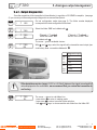
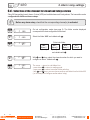
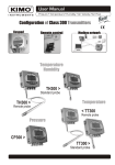
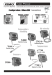
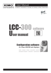
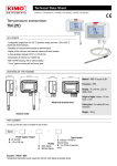
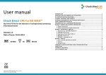
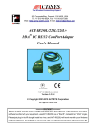
User Manual
New
Configuration of Class 200 transmitters
Keypad
Air velocity
Pressure
< CTV210
CP200 >
Temperature
Humidity
TH200 >
Remote probe
< TH200
Standard probe
SENTRONIC AG
Produkte, Support und Service
Rugghölzli 2
CH - 5453 Busslingen
Tel. +41 (0)56 222 38 18
Fax +41 (0)56 222 10 12
[email protected]
www.sentronic.com
SENTRONIC AG
Produkte, Support und Service
Rugghölzli 2
CH - 5453 Busslingen
Tel. +41 (0)56 222 38 18
Fax +41 (0)56 222 10 12
[email protected]
www.sentronic.com
Table of contents
1. Prerequired . . . . . . . . . . . . . . . . . . . . . . . . . . . . . . . . . . . . . . . . . . . . . . . . . . . . . . . . . . . . . . . . . . . . . . . . . . . . . . . . . . . . . . . . P 1
1.a - Working principle . . . . . . . . . . . . . . . . . . . . . . . . . . . . . . . . . . . . . . . . . . . . . . . . . . . . . . . . . . . . . . . . . . . . . . . . P 1
1.b - Output signal selection . . . . . . . . . . . . . . . . . . . . . . . . . . . . . . . . . . . . . . . . . . . . . . . . . . . . . . . . . . . . . . . . . . P 1
1.c - Protection tip of the sensor . . . . . . . . . . . . . . . . . . . . . . . . . . . . . . . . . . . . . . . . . . . . . . . . . . . . . . . . . . . . . P 1
2. Code activation and access to functions . . . . . . . . . . . . . . . . . . . . . . . . . . . . . . . . . . . . . . . . . . . . . . . P 2
3. Display and keypad configuration •
F100 . . . . . . . . . . . . . . . . . . . . . . . . . . . . . . . . . . . . . . . . . . . . . . P 3
3.a - Backlight . . . . . . . . . . . . . . . . . . . . . . . . . . . . . . . . . . . . . . . . . . . . . . . . . . . . . . . . . . . . . . . . . . . . . . . . . . . . . . . . . P 3
3.b - Display contrast control . . . . . . . . . . . . . . . . . . . . . . . . . . . . . . . . . . . . . . . . . . . . . . . . . . . . . . . . . . . . . . . . . P 3
3.c - Keypad locking . . . . . . . . . . . . . . . . . . . . . . . . . . . . . . . . . . . . . . . . . . . . . . . . . . . . . . . . . . . . . . . . . . . . . . . . . . . P 4
4. Configuring channels and units of measurement •
F200 . . . . . . . . . . . . . . . . . . . . . . . . P
5
5. Analogue output management •
F300 . . . . . . . . . . . . . . . . . . . . . . . . . . . . . . . . . . . . . . . . . . . . . . . . . . . P 6
5.a - Output diagnostics . . . . . . . . . . . . . . . . . . . . . . . . . . . . . . . . . . . . . . . . . . . . . . . . . . . . . . . . . . . . . . . . . . . . . . . P 7
5.b - Analogue output settings . . . . . . . . . . . . . . . . . . . . . . . . . . . . . . . . . . . . . . . . . . . . . . . . . . . . . . . . . . . . . . . . P 8
6. Relay / Alarm settings •
F400. . . . . . . . . . . . . . . . . . . . . . . . . . . . . . . . . . . . . . . . . . . . . . . . . . . . . . . . . . . . . . P 10
6.a - Activation / Deactivation of BEEP alarm . . . . . . . . . . . . . . . . . . . . . . . . . . . . . . . . . . . . . . . . . . . . . . P 10
6.b - Relay security . . . . . . . . . . . . . . . . . . . . . . . . . . . . . . . . . . . . . . . . . . . . . . . . . . . . . . . . . . . . . . . . . . . . . . . . . . P 10
6.c - Alarm/relay functions and LED colour codes . . . . . . . . . . . . . . . . . . . . . . . . . . . . . . . . . . . . . . . . . P 11
6.d - Channel selection for alarms/ relays . . . . . . . . . . . . . . . . . . . . . . . . . . . . . . . . . . . . . . . . . . . . . . . . . . P 12
6.e - Alarm mode details . . . . . . . . . . . . . . . . . . . . . . . . . . . . . . . . . . . . . . . . . . . . . . . . . . . . . . . . . . . . . . . . . . . . . P 13
6.f - Alarm mode selection . . . . . . . . . . . . . . . . . . . . . . . . . . . . . . . . . . . . . . . . . . . . . . . . . . . . . . . . . . . . . . . . . . P 15
6.g - Setpoints and time-delay setting . . . . . . . . . . . . . . . . . . . . . . . . . . . . . . . . . . . . . . . . . . . . . . . . . . . . . . P 16
7. Pressure measurement configuration •
F500 . . . . . . . . . . . . . . . . . . . . . . . . . . . . . . . . . . . . . . . P 18
7.a - Pressure measurement integration (CP 200) . . . . . . . . . . . . . . . . . . . . . . . . . . . . . . . . . . . . . . . . P 18
7.b - Autozero . . . . . . . . . . . . . . . . . . . . . . . . . . . . . . . . . . . . . . . . . . . . . . . . . . . . . . . . P 18
8. Humidity measurement configuration •
F500 . . . . . . . . . . . . . . . . . . . . . . . . . . . . . . . . . . . . . . . P 19
8.a - Offset settings in Humidity and temperature (TH 200) . . . . . . . . . . . . . . . . . . . . . . . . . . . . . . P 19
9. Air velocity measurement configuration •
F600 . . . . . . . . . . . . . . . . . . . . . . . . . . . . . . . . . . . P 20
9.a - Temperature compensation (CP 200) . . . . . . . . . . . . . . . . . . . . . . . . . . . . . . . . . . . . . . . . . . . . . . . . P 20
9.b - Air velocity coefficient selection (CP 200) . . . . . . . . . . . . . . . . . . . . . . . . . . . . . . . . . . . . . . . . . . . . P 21
9.c - Air velocity correction coefficient input (CP and CTV 210) . . . . . . . . . . . . . . . . . . . . . . . . . . P 22
Class 200 transmitter configuration via keypad
SENTRONIC AG
Produkte, Support und Service
Rugghölzli 2
CH - 5453 Busslingen
Tel. +41 (0)56 222 38 18
Fax +41 (0)56 222 10 12
[email protected]
www.sentronic.com
Table of contents
10. Airflow measurement configuration •
F600 . . . . . . . . . . . . . . . . . . . . . . . . . . . . . . . . . . . . . . . . P
23
11. Other functions . . . . . . . . . . . . . . . . . . . . . . . . . . . . . . . . . . . . . . . . . . . . . . . . . . . . . . . . . . . . . . . . . . . . . . . . . . . . . . . . P 26
11.a - Activation / Deactivation of the RS232 . . . . . . . . . . . . . . . . . . . . . . . . . . . . . . . . . . . . . . . . . . . . . . P 26
11.b - Serial number display. . . . . . . . . . . . . . . . . . . . . . . . . . . . . . . . . . . . . . . . . . . . . . . . . . . . . . . . . . . . . . . . . P 26
11.c - Purge Mode . . . . . . . . . . . . . . . . . . . . . . . . . . . . . . . . . . . . . . . . . . . . . . . . . . . . . . . . . . . . . . . . . . . . . . . . . . . P 27
12. Error codes . . . . . . . . . . . . . . . . . . . . . . . . . . . . . . . . . . . . . . . . . . . . . . . . . . . . . . . . . . . . . . . . . . . . . . . . . . . . . . . . . . . . . P 30
13. Functions recap . . . . . . . . . . . . . . . . . . . . . . . . . . . . . . . . . . . . . . . . . . . . . . . . . . . . . . . . . . . . . . . . . . . . . . . . . . . . . . . P 31
SENTRONIC AG
Class 200 transmitter configuration via keypad
Produkte, Support und Service
Rugghölzli 2
CH - 5453 Busslingen
Tel. +41 (0)56 222 38 18
Fax +41 (0)56 222 10 12
[email protected]
www.sentronic.com
1. Prerequired
1.a - Working principle
Using keypad, you can activate (or deactivate) a channel, change the measuring range, set the set points and timedelay...
®
Principle: the configuration options are accessed via folders and sub-folders (similar to Windows ). Access is
made via a numerical code (full details in this manual).
Meaning of the keys
Visual alarm
LED
AL1
AL2
R
16-digit 2-line
display
CODE:
0000
Keypad
To increment a value or a level
To decrement a value or a level
To validate an input
To cancel an input or to return to the previous step
1.b - Output signal selection
Voltage or Current ?
The Class 200 can output either a voltage or a current signal.
With the on-off switch located on the left
top of the transmitter (when open), you can
choose analogue output 0-10V (voltage)
or 4-20 mA (current)
Down
0-10 V
Up
4-20 mA
1.c - Protection tip of the sensor
!
It's extremely unwise to remove the protection tip of our hygrometry
probes as the sensitive element is very fragile even to light contacts.
However, if you have to remove the protection tip, take all possible
precautions and avoid any contact with the sensitive element.
To remove the protection tip, unscrew it or unclip it.
Class 200 transmitter configuration via keypad
SENTRONIC AG
Produkte, Support und Service
Rugghölzli 2
CH - 5453 Busslingen
Protection tip
to unscrew
Protection tip
to unscrew
Tel. +41 (0)56 222 38 18
Fax +41 (0)56 222 10 12
Sensitive
element
Sensitive
element
Page 1
[email protected]
www.sentronic.com
2. Code activation and access to functions
This step is COMPULSORY for each configuration.
!
To access the transmitter functions, and for safety, you have to first enter a safety code.
• Please check that the transmitter is powered on.
• If the transmitter displays an error code, please see “Errors Code” section on page 29
Step 1
The first “0” blinks, which means that this column is activated and you can
enter data from the keypad.
Press
to get this screen
CODE:
0000
Step 2
Enter the CODE “0101”
with the keypad and
validate with
CODE:
0101
Step 3
This screen appears
>
F
The code must be entered from left to right.
To increment a value or a level, press
To decrement a value or a level, press
To validate a value (level) or to validate the code, press
To return to the previous status or to cancel, press
This screen confirms that the code was correctly entered, and that you can
configure the transmitter.
If the code was wrongly entered, the transmitter initializes and returns to the
starting display.
100
>
Shows the ongoing
modification
Note : here, only one line
is modifiable
Step 4
Configuration folder
selection
>
F
100
F
100
“F” as
“Function”
Configuration folder number
The transmitter includes 6 folders
maximum :
• 100
• 200
• 300
• 400
• 500
• 600
Ex. In the folder 400, you can configure
the alarms and relays. See page 10.
To select your configuration folder, press to increment 100 or press
decrement 100.
Once the folder is selected, press
to validate.
to
On the top left of each page of this manual, you can find a reminder of the
configuration folder where the function is available.
F400
Class 200 transmitter configuration via keypad
Page 2
SENTRONIC AG
Produkte, Support und Service
Rugghölzli 2
CH - 5453 Busslingen
Tel. +41 (0)56 222 38 18
Fax +41 (0)56 222 10 12
[email protected]
www.sentronic.com
F100
3. Display and keypad configuration
3.a - Backlight
With the backlight, the reading is easier with more contrast, if the ambient light is weak.
You can activate or deactivate it.
Step
1
Go into the configuration mode (see page 2). The folder number displayed
corresponds to the last folder used.
>
F
100
2
>
F
100
Step
>
F
101
01
Select the sub-folfer “101” and validate with .
The cursor > goes to the line of available choices.
101
With and keys, select 00 to deactivate the backlit or 01 to activate.
Validate with .
101
01
The cursor > returns to sub-folders line.
• press twice to return to reading mode.
• press once to select another folder.
• with and keys, you can choose another sub-folder from the folder
100
Step
3
Step
4
>
Step
>
5
F
F
01
Select the folder “100” and validate with
.
3.b - Display contrast control
Step
1
Go into configuration mode (see page 2). The folder number which appears
corresponds to the last configuration folder used.
>
F
100
2
>
F
100
Step
>
F
102
05
Select the sub-folder “102” and validate with .
The cursor > goes to the line of available choices.
102
With
102
08
The cursor > returns to sub-folders line.
• press twice to return to reading mode.
• press once to return to another folder selection.
• with and keys, you can choose another sub-folder from folder 100.
Step
3
Step
4
>
Step
>
5
F
F
08
Select the folder “100” and validate with
and
keys, set the contrast required (from 0 to 10). Validate with .
Class 200 transmitter configuration via keypad
SENTRONIC AG
Produkte, Support und Service
.
Rugghölzli 2
CH - 5453 Busslingen
Tel. +41 (0)56 222 38 18
Fax +41 (0)56 222 10 12
Page 3
[email protected]
www.sentronic.com
F100
3. Display and keypad configuration
3.c - Keypad locking
For safety, you can lock the keypad access. Like on a mobile phone, the keys will be disabled after having been
locked.
Step
1
Go into configuration mode (see page 2). The folder number which appears
corresponds to the last folder used.
>
F
100
2
>
F
100
Step
>
F
104
00
Select the sub-folder “104” and validate .
The cursor > goes to the different choices available.
F
104
With and keys, select 01 to lock the keypad access or 00 if you do
not want to lock the keypad. Validate with .
F
104
01
Step
3
Step
4
>
Step
>
5
!
01
Select the folder “100” and validate with
.
The cursor > returns to sub-folders line.
• press twice to return to reading mode.
• press once to return to another folder selection.
• with and keys to choose another sub-folder from the folder 100
To unlock keypad access, press and hold the
key for 10 seconds.
After 10 seconds, an audible signal confirms that the keypad is unlocked.
Page 4
SENTRONIC AG
Class 200 transmitter configuration via keypad
Produkte, Support und Service
Rugghölzli 2
CH - 5453 Busslingen
Tel. +41 (0)56 222 38 18
Fax +41 (0)56 222 10 12
[email protected]
www.sentronic.com
F200 4. Configuring channels and units of measurement
Class200 transmitters have 2 measuring channels. You can activate 1, or 2 channels and select each unit of
measurement.
Step
1
Go into configuration mode (see page 2). The folder number displayed
corresponds to the last configuration folder used.
>
F
100
2
>
F
200
Step
>
F
200
01
Select sub-folder “200”
Select sub-folder “201”
and validate with . The cursor > goes to choices line
F
200
With
and
keys, select the unit of measurement (see chart below).
Validate with .
Step
3
Step
4
>
04
Select the folder “200” and validate with .
Channel n°2
Channel n°1
CP201 et 202 CP203 et 204
TH200
00
Iinactive channel Inactive channel
Inactive channel
CTV210
01
Pa
mbar
°C
m/s
02
mmH2O
inWg
°F
fpm
03
inWg
KPa
%RH
°C
04
mbar
PSI
g/Kg (absolute humid. ñ)
°F
05
mmHg
mmHg
°C (dew temp. Td)
m3/h
06
m/s
m/s
°F (dew temp. Td)
L/s
07
fpm
fpm
°C (Humid temp. Tw)
cfm
08
m3/h
m3/h
°F (Humid temp. Tw)
m3/s
09
L/s
L/s
KJ/Kg (Enthalpy i)
10
cfm
cfm
11
m3/s
m3/s
Inactive channel
For a CP 200 transmitter (201, 202, 203 and 204),the SQR option is required in order to activate the
units of air velocity and airflow (from 06 to 11)
Step
5
>
F
200
04
The cursor > returns to sub-folders line.
• press twice to return to reading mode.
• press once to return to another folder selection.
• with and keys to choose another sub-folder from the folder 200.
Class 200 transmitter configuration via keypad
SENTRONIC AG
Produkte, Support und Service
Rugghölzli 2
CH - 5453 Busslingen
Tel. +41 (0)56 222 38 18
Fax +41 (0)56 222 10 12
Page 5
[email protected]
www.sentronic.com
F300
5. Analogue output management
5.a - Output diagnostics
With this function, you can check with a multimeter (or a regulator/display, or a PLC/BMS) if the transmitter outputs
are working properly. The transmitter generates a voltage of 0 V, 5 V and 10 V or a current of 4 mA, 12 mA and
20 mA.
5.a.1 - Multimeter connection configuration
Before carrying out the output diagnostics, all connections and configurations of the transmitter must be
enabled, to avoid any damage on the transmitter and the multimeter !
Step
1
First, select a channel for the output diagnostics.
Selection of the channel
to be checked
The channel numbers are indicated on the
board located below the terminal block.
Channel n°1
Step
2
Channel n°2
Example of
connection
On the photo alongside, the multimeter is
connected to the 0-10 V output and channel
n°1.
Analogue output 1
Analogue output 2
ge
ge
ta
ta
ol und
ol und
v
v
... gro ent
... gro ent
...
...
... ...... curr
... ...... curr
.
.
.
.
... ..... .....
... ..... .....
V
V
0 ...... ......
0 ...... ......
1
1
0- D
0- D
A
A
N
N
G 20 m
G 20 m
44-
B
-
Relay 2
A
+
n
n
e
op
e
op
ly
ly
d
d
al
al
se
se
n
n
m
m
lo
lo
or mo
or mo
c
c
n
n
ly
ly
..
..
... ..com mal
... ..com mal
...
...
r
r
.. .. .... no
.. .. .... no
. .... ....
NO M ......
CO ...
NC
. .... ....
NO M ......
CO ...
NC
24 Vdc / ac
230 Vac
115 Vac
[
The ticked box show
the power supply
type of the transmitter
(230 Vac shown above).
Class 200 transmitter configuration via keypad
Page 6
SENTRONIC AG
Relay 1
Produkte, Support und Service
Rugghölzli 2
CH - 5453 Busslingen
Tel. +41 (0)56 222 38 18
Fax +41 (0)56 222 10 12
[email protected]
www.sentronic.com
5. Analogue output management
F300
5.a.2 - Output diagnostics
Once the connection of the transmitter to the multimeter (or regulator or PLC/BMS is complete, (see page
6), you can carry out the analogue output diagnostics on several check points.
Step
1
>
F
100
2
>
F
300
Step
>
F
300
00
Step
3
Step
4
>
F
300
04
Go into configuration mode (see page 2). The folder number displayed
corresponds to the last configuration folder used.
Select the folder “300” and validate with
.
Channel n° 2 output
Channel n° 1 output
Select sub-folder “303”
Select sub-folder “300”
and validate with .
The cursor > goes to available choices..
With
and
keys, select the signal that the transmitter must output (see
chart below). Note : no need to validate with .
Diagnostic output
5
0V
01
5V
02
10 V
03
4 mA
04
12 mA
05
20 mA
If the deviations are too large(>0,05V or >0,05mA) between the signal issued and the
value displayed on the multimeter, we recommend that you return the transmitter to
our factory.
!
Step
00
>
F
300
04
The cursor > returns to sub-folders line.
• press twice
to return to reading mode.
• press once to return to another folder selection.
• with and keys to choose another sub-folder from the folder 300.
Class 200 transmitter configuration via keypad
SENTRONIC AG
Produkte, Support und Service
Rugghölzli 2
CH - 5453 Busslingen
Tel. +41 (0)56 222 38 18
Fax +41 (0)56 222 10 12
Page 7
[email protected]
www.sentronic.com
5. Analogue output management
F300
5.b - Analogue output settings
With this function, you can modify the measuring range of the transmitter, and you can equate the new limits to the
analogue output (0-10V or 4-20mA).
You can enter the measuring range required on your own !
!
You must enter the values according to the units of measurement selected, not
according to the measuring range of the transmitter.
Ex. on a CP 201 pressure transmitter (0 to ±1000 Pa) with a reading in mmH2O, the minimum and maximum ranges must be
configured on measuring range of 0 to ±102 mmH2O. See conversion chart on following page.
Step
1
>
F
100
2
>
F
300
Step
>
F
301
Step
3
-100
Step
F 301
> -00100
Step
>
Step
F 302
> +00500
4
5
6
!
Etape
Step
7
F
302
+500
Go into configuration mode (see page 2). The folder number displayed
corresponds to the last configuration folder used.
Select the folder “300” and validate with
.
Minimum of Channel n°1
Minimum of Channel n°2
output
output
Select sub-folder “301”
Select sub-folder “304”
and validate with . The cursor > returns to the input line.
With and keys, select the value sign: negative or positive, validate with
. Then, enter the minimum limit value and validate with .
Maximum of Channel n°1
Maximum of Channel n°2
output
output
Select sub-folder “302”
Select sub-folder “305”
and validate with . The cursor > goes to the input line.
With and keys, select the value sign: negative or positive, validate with
.
Then, enter the maximum limit value and validate with .
We recommend that the interval between the minimum and maximum is > 5% of the measuring
range.
>
F
302
+500
The cursor > goes to sub-folders line.
• press twice to return to reading mode.
• press once to return to another folder selection.
• with and keys you can choose another sub-folder from the folder
300.
After an analogue output setting, if the unit of measurement is modified (see page 5), you have to reconfigure the
outputs according to the new unit of measurement.
Page 8
SENTRONIC AG
Class 200 transmitter configuration via keypad
Produkte, Support und Service
Rugghölzli 2
CH - 5453 Busslingen
Tel. +41 (0)56 222 38 18
Fax +41 (0)56 222 10 12
[email protected]
www.sentronic.com
F300
5. Analogue output management
5.b.1 - Units of measurement conversion chart
Pressure
CP201
CP202
CP 203
CP 204
Pa
mmH2O
inWg
mbar
mmHg
KPa
PSI
0 to ±1000
0 to ±102,0
0 to ± 4,015
0 to ±10,00
0 to ±7,50
-
-
0 to ±10000
0 to ±1020,0 0 to ±40,15
0 to ±100,00
0 to ±75,00
-
-
-
-
0 to ±200,0
0 to ±500
0 to ±375
0 to ±50,0
0 to ±7,50
-
-
0 to ±800,0
0 to ±2000
0 to ±1500
0 to ±200,0 0 to ±30,00
Temperature
°C
TH200 - St.steel probe
TH 200 - PC probe
CTV 210
°F
-40,0 to +180,0 -40,0 to +356,0
-20,0 to +80,0
-4,0 to +176,0
0,0 to +50,0
+32,0 to +122,0
Air velocity (CTV 210)
CTV210
m/s
fpm
0,0 to 30,0
0 to 5905
Class 200 transmitter configuration via keypad
SENTRONIC AG
Produkte, Support und Service
Rugghölzli 2
CH - 5453 Busslingen
Tel. +41 (0)56 222 38 18
Fax +41 (0)56 222 10 12
Page 9
[email protected]
www.sentronic.com
F400
6. Alarm / relay settings
6.a - Activation / Deactivation of BEEP alarm
The beep alarm (audible alarm) is activated when a set point is reached.
For more details on the setpoint settings, see page 16.
Step
1
>
F
100
2
>
F
400
Step
>
F
Step
3
Step
4
>
Step
>
5
Entrer en mode configuration (cf. page 2). Le numéro de dossier affiché
correspond au dernier dossier de configuration utilisé.
Select the folder “400” and validate with
.
400
01
Select sub-folder “400” and validate with
The cursor > goes to available choices.
.
F
400
With
and
keys, select
deactivate. Validate with .
F
400
01
The cursor > goes to sub-folders line.
• press twice to return to reading mode.
• press once to return to another folder selection.
• with and keys you can choose another sub-folder from the folder 400.
01
01
to activate the BEEP alarm or
00
to
6.b - Relay security
The relay outputs are by default, in negative security: the relay is energized when a set point is reached.
With the keypad, you can swap the relays in positive security : then, the relay is de-energized when a set point is
reached or during a power outage.
Step
1
>
F
100
2
>
F
400
Step
>
F
401
01
F
401
F
401
01
Step
3
Step
4
>
Step
>
5
01
Select folder “400” and validate with
.
Select sub-folder “401” and validate with .
The cursor > goes to available choices.
Le curseur > descend sur la ligne des choix possibles.
With and keys, select 01 for a positive security or 00 for a negative
security. Validate with .
The cursor > returns to sub-folders line.
• press twice on to return to reading mode.
• press once on to return to another folder selection.
• with and keys, you can choose another sub-folder from the folder 400.
Class 200 transmitter configuration via keypad
Page 10
SENTRONIC AG
Enter in configuration mode (see page 2). The folder number displayed
corresponds to the last configuration folder used.
Produkte, Support und Service
Rugghölzli 2
CH - 5453 Busslingen
Tel. +41 (0)56 222 38 18
Fax +41 (0)56 222 10 12
[email protected]
www.sentronic.com
6. Alarm / relay settings
F400
6.c - Alarm / relay functions and LED colour codes
6.c.1 - Visual / audible alarms
Class 200 transmitters have 2 visual / audible alarms located in front of the transmitter, allowing to know the
condition of the setpoints.
Alarm n°1
Alarm LED colour codes
Alarm n°2
Green
The alarm function is activated and
the set point is not reached
Red
The alarm function is activated and
the setpoint is reached
The alarm function is not activated
None
The red LED appears when the setpoint is reached,
taking into account the time-delay and the action type
(falling or rising).
See page 13 for more details.
Audible alarm
Once the alarm is activated, an alarm sounds
whilst the setpoint is reached.
The BEEP alarm function must be activated to use the
audible alarm. See page 10.
6.c.2 - Les relais
Class 200 transmitters have 2 relays visible on the transmitter board. These 2 relays each have one LED to
allow real-time checking.
Relay n°1
LED
Relay n°1
Relay n°2
LED
Relay n°2
Relay LED colour codes
Red
The relay is energized
None
The relay is not energized
or has not been configured
The relay is energized when the setpoint is reached,
taking into account the time-delay, the action type and
also the alarms security mode.
Set points, time-delay and action type setting: see page
16
Alarm security settings : see page 10
Class 200 transmitter configuration via keypad
SENTRONIC AG
Produkte, Support und Service
Rugghölzli 2
CH - 5453 Busslingen
Tel. +41 (0)56 222 38 18
Fax +41 (0)56 222 10 12
Page 11
[email protected]
www.sentronic.com
6. Alarm / relay settings
F400
6.d - Selection of the channel for visual and relays alarms
Class 200 transmitters have 4 alarms: 2 visual (LED) and audible alarms and 2 relay alarms. The transmitter can be
configured with 4 different alarms setups.
!
Before any alarm setup, check that the corresponding channel(s) is activated.
Step
1
>
F
100
2
>
F
400
Step
>
F
402
01
Step
3
Go into configuration mode (see page 2). The folder number displayed
corresponds to the last configuration folder used.
Select the folder “400” and validate with
“402”
Alarm 1
(Led 1)
.
Select sub-folder
“407”
“412”
Alarm 2
Relay 1
(Led 2)
and validate with
Step
4
Step
5
>
>
F
402
F
402
01
01
Page 12
SENTRONIC AG
“417”
Relay 2
.
With and keys, select the channel number for which you want to
configure an alarm. Validate with .
The cursor > returns to sub-folders line.
• press twice to return to reading mode.
• press once to return to another folder selection.
• with and keys, you can choose another sub-folder from the folder 400
(i.e. for example to configure another alarm / relay)
Class 200 transmitter configuration via keypad
Produkte, Support und Service
Rugghölzli 2
CH - 5453 Busslingen
Tel. +41 (0)56 222 38 18
Fax +41 (0)56 222 10 12
[email protected]
www.sentronic.com
F400
6. Alarm / relay settings
6.e - Alarm mode details
6.e.1 - Definitions
Seuil
The setpoint is a limit which, on being reached and/or exceeded , activates an alarm or energizes a relay (in negative
security, see page 10 for more details).
Time-delay
Once the setpoint is reached and/or exceeded, the time-delay postpones the alarm activation (or relay excitation) for a
short period (in seconds). Once this period is elapsed, and if the setpoint is still exceeded, then the alarm is activated or the relay is
energized (in negative security).
Action type
For alarm activation or relay excitation, you can choose the action type: rising or falling action.
• Rising action: the alarm is activated once the measurement goes over the setpoint
• Falling action: the alarm is activated once the measurement goes below the setpoint
6.e.2 - Available configurations
Configuration N°1 : 2 setpoints and time-delay activated (Control Mode)
Setpoint 1 > Setpoint 2
Measurement
Alarm set
<T> Time-delay
Setpoinl 1
Setpoint 2
<T>
<T>
<T>
Time
Energized
Not energized
Relay status
Negative security
Energized
Not energized
Relay status
Positive security
Control mode (or
regulation mode)
=>you can regulate the
measurement within a
range determined by 2
setpoints.
Setpoint 2 > Setpoint 1
Measurement
Alarm set
<T> Time-delay
Setpoint 2
Setpoint 1
<T>
<T>
<T>
Time
Energized
Not energized
Relay status
Negative security
Energized
Not energized
Relay status
Positivee security
Class 200 transmitter configuration via keypad
SENTRONIC AG
Produkte, Support und Service
Rugghölzli 2
CH - 5453 Busslingen
Tel. +41 (0)56 222 38 18
Fax +41 (0)56 222 10 12
Page 13
[email protected]
www.sentronic.com
F400
6. Alarm / relay settings
Configuration N°2 : 1 setpoint, time-delay and rising action activated
Measurement
Alarm set
<T> Time-delay
Setpoint 1
<T>
<T>
<T>
Time
Energized
Not energized
Relay status
Negative security
Energized
Not energized
Relay status
Positive security
Configuration N°3 : 1 setpoint, time-delay and falling action activated
Measurement
Alarm set
<T> Time-delay
Setpoint 1
<T>
<T>
<T>
Time
Energized
Not energized
Relay status
Negative security
Energized
Not energized
Relay status
Positive security
Class 200 transmitter configuration via keypad
Page 14
SENTRONIC AG
Produkte, Support und Service
Rugghölzli 2
CH - 5453 Busslingen
Tel. +41 (0)56 222 38 18
Fax +41 (0)56 222 10 12
[email protected]
www.sentronic.com
F400
6. Alarm / relay settings
6.f - Alarm mode selection
Step
1
>
F
100
2
>
F
400
Step
>
F
403
02
Step
3
Go into configuration mode (see page 2). The folder number displayed
corresponds to the last configuration folder used.
Select the folder “400” and validate with .
Mode
Alarm 1
“403”
Select sub-folder
Alarm 2
Relay 1
“408”
“413”
and validate with
Step
4
Step
5
>
>
F
F
403
02
403
02
Produkte, Support und Service
.
With and keys, select the code relative to the alarm mode (see chart
below). Validate with .
Code
Alarm mode
00
No alarm
01
2 setpoints with time-delay (control mode)
N° 1 page 13
02
1 setpoint with time-delay and rising action
N° 2 page 14
03
1 setpoint with time-delay and falling action
N° 3 page 14
Drawing
The cursor > returns to sub-folders line.
• press twice to return to reading mode.
• press once to return to another folder selection.
• with and keys, you can choose another sub-folder from the folder
400.
Class 200 transmitter configuration via keypad
SENTRONIC AG
Relay 2
“418”
Rugghölzli 2
CH - 5453 Busslingen
Tel. +41 (0)56 222 38 18
Fax +41 (0)56 222 10 12
Page 15
[email protected]
www.sentronic.com
6. Alarm / relay settings
F400
6.g - Setpoints and time-delay setting
6.g.1 - Setpoints
Step
1
>
F
100
2
>
F
400
Step
>
F
404
02
Step
3
Go into configuration mode (see page 2). The folder number displayed
corresponds to the last configuration folder used.
Select the folder “400” and validate with
Alarm 1
Setpoint 1 “404”
.
Select sub-folder
Alarm 2
Relay 1
“409”
“414”
Relay 2
“419”
To configure the setpoint 2 (alarm in control mode, see p13),
Setpoint 2 “405”
select sub-folder
“410”
and validate with
Step
4
!
F 404
> -00100
“415”
“420”
.
With and keys, select the value sign: negative or positive. Validate with
.
Then, enter the setpoint value and validate with .
You must enter values according to the units of measurement selected, not
according to the measuring range of the transmitter.
Ex. on a CP 201 pressure transmitter (0 to ±1000 Pa) with a reading in mmH2O, the minimum and maximum ranges must be
configured on measuring range of 0 to ±102 mmH2O. See conversion chart on page 9.
Step
5
>
F 404
-100
The cursor > returns to sub-folders line.
• press twice to return to reading mode.
• press once to return to another folder selection.
• with and keys, you can choose another sub-folder from the folder
400.
If after having set up a setpoint, the unit of measurement is modified (see page 5), then you have to reconfigure
the setpoints according to this new unit of measurement.
Page 16
SENTRONIC AG
Class 200 transmitter configuration via keypad
Produkte, Support und Service
Rugghölzli 2
CH - 5453 Busslingen
Tel. +41 (0)56 222 38 18
Fax +41 (0)56 222 10 12
[email protected]
www.sentronic.com
F400
6. Alarm / relay settings
6.g.2 - Time-delay
Step
1
>
F
100
2
>
F
400
Step
>
F
406
02
Step
3
Go into configuration mode (see page 2). The folder number displayed
corresponds to the last configuration folder used.
Select the folder “400” and validate with
Tempo
Alarm 1
“406”
.
Select sub-folder
Alarm 2
Relay 1
“411”
“416”
and validate with
Step
4
>
Step
>
5
.
F
406
With and keys, set the required time-delay: from 00 to 60 seconds.
If you do not need the time-delay, enter 00.
Validate with .
F
406
15
The cursor > returns to sub-folders line.
• press twice to return to reading mode.
• press once to return to another folder selection.
• with and keys , you can choose another sub-folder from the folder 400.
15
Class 200 transmitter configuration via keypad
SENTRONIC AG
Relay 2
“421"
Produkte, Support und Service
Rugghölzli 2
CH - 5453 Busslingen
Tel. +41 (0)56 222 38 18
Fax +41 (0)56 222 10 12
Page 17
[email protected]
www.sentronic.com
7. Pressure measurement configuration
F500
7.a - Pressure measurement integration
The pressure measurement element is very sensitive and reacts to pressure changes. When making
measurements in unstable air movement conditions, the pressure measurement may fluctuate. The integration
coefficient (from 0 to 9) makes an average of the measurements ; this helps to avoid any excessive variations and
guarantees a stable measurement.
This value is applicable when the variation is less than +/- (Coef. x 10 Pa)
Example : CP201 (0-1000 Pa) - First measurement: 120 Pa - New measurement : 125 Pa
The pressure source is stable, the user applied a low integration. Integration : 1, maximum variation allowed +/-10 Pa. Since the variation is
less than 10 Pa, we apply the integration calculation formula. Next measurement displayed ((9 * 125) + (1 *120 ))/10 = 124.5 soit 124 Pa. If
the new value had been 131 Pa, the next value displayed would have been 100% of the new value, i.e 131 Pa.
!
Function only available on pressure transmitters:
CP 201, CP 202, CP 203 and CP 204
Step
1
>
F
100
>
F
500
F
500
09
F
500
Step
2
Step
3
>
Step
4
>
09
Step
5
>
F
500
Go into configuration mode (see page 2). The folder number displayed
corresponds to the last configuration folder used.
Select the folder “500” and validate with
.
Select the sub-folder “500” and validate with
The cursor > returns to available choices.
With
and
.
keys, you can set the integration value: from 00 to 09.
Validate with .
Coefficient 0 : no integration, large variation of the measurement
displayed.
Coefficient 9 : maximum integration, more stable measurement display.
The cursor > returns to sub-folder selection
• press once
to return to reading mode
• or choose another folder to access other functions.
7.b - Autozero
Thanks to the temperature compensation of the gain (from 0 to 50°C) and to the manual auto-zero, Class 200
transmitters guarantee an excellent long-term stability, along with great measurement accuracy (in low and high
ranges). The autozero compensates for any long-term drifts of the sensitive element, with the manual adjusting of
the zero.
To autozero, unplug the 2 pressure connections tubes, and press on the AUTOZERO key (see “connection”).
If the pressure transmitter has a display screen, it’s possible to autozero by pressing the Esc button for 5
seconds.
Page 18
SENTRONIC AG
Class 200 transmitter configuration via keypad
Produkte, Support und Service
Rugghölzli 2
CH - 5453 Busslingen
Tel. +41 (0)56 222 38 18
Fax +41 (0)56 222 10 12
[email protected]
www.sentronic.com
8. Humidity measurement configuration
F500
8.a - Offset setting in humidity and temperature
In order to compensate for any longterm drift of the transmitter, you can add an offset to the value displayed by the
TH 200 with the EHK 500 reference portable instrument or via the keypad.
! Function only available on humidity transmitters: TH 200
The EHK 500 is a reference portable instrument (optional) which enables you to adjust at one point the
humidity and temperature reading, via the RS 232 connection cable. Thanks to this new time-saving
system, no need to return the transmitter to our factory.
Your transmitter is always available on site. For more details, see technical datasheet and user manual of
EHK 500.
Step
1
8.a.1 - Offset in hygrometry
>
F
100
>
F
500
F
500
10
Step
2
Step
3
Step
4
>
F 500
> +0010,0
Step
5
>
F
500
Go into the configuration mode (see page 2). The folder number displayed
corresponds to the last folder used.
Select folder “500” and validate with
.
Select sub-folder “500” and validate with .
The cursor > goes to the line of available choices.
With keys and
Validate with .
, enter the offset value: from
-50,0 to +50,0.
The cursor > returns to sub-folders line.
• press once on
to return to reading mode.
• or choose another folder to access other functions.
8.a.2 - Offset in temperature
Step
1
F
100
>
F
500
F
501
3,2
Select sub-folder “501” for an offset in °C or “502” for an offset in °F and
validate with .
The cursor > goes to the line of available choices.
F 501
> +0003,2
With keys and , enter the offset value: from -50,0 to +50,0 (in
°C) or from -90 to +90 (in °F). Validate with .
Step
2
Step
3
Step
4
>
Step
5
Go into the configuration mode (see page 2). The folder number displayed
corresponds to the last folder used.
>
>
F
500
Select folder “500” and validate with
.
The cursor > returns to folders line.
• press once on
to return to reading mode.
• or choose another folder to access other functions.
If you activate the offset in temperature in °C (function 501), the value entered is automatically converted
into °F (function 502) and vice versa.
Class 200 transmitter configuration via keypad
SENTRONIC AG
Produkte, Support und Service
Rugghölzli 2
CH - 5453 Busslingen
Tel. +41 (0)56 222 38 18
Fax +41 (0)56 222 10 12
Page 19
[email protected]
www.sentronic.com
F600
9. Air velocity measurement configuration
9.a - Temperature compensation
You can modify the temperature compensation value.
The air velocity and airflow measured with a differential probe (such as Pitot tube, Debimo blade,orifice plate...)
depends on the working temperature. Then, it is required to enter the working temperature to get more
accurate results.
! Function available only on pressure transmitters: CP 200
Step
1
>
F
100
2
>
F
600
Step
>
F
600
20
F
600
20
F
600
20
Step
3
Step
4
>
Step
>
5
Go into configuration mode (see page 2). The folder number displayed
corresponds to the last configuration folder used.
Select the folder “600” and validate with
.
Select the sub-folder “600” to enter a value in °C
or "601" to enter a value in °F, validate with .
The cursor > returns to available choices.
With and keys, enter the temperature compensation (Celsius degree
shown alongside, sub-folder "600"). Validate with .
The cursor > returns to sub-folders line.
• press twice to return to reading mode.
• press once to return to another folder selection.
• with and keys, you can choose another sub-folder from the folder
600.
If you make a temperature compensation in Celsius degree (sub-folder "600"), the transmitter will automatically
make the conversion into Farenheit degree (sub-folder "601") and vice versa.
Page 20
SENTRONIC AG
Class 200 transmitter configuration via keypad
Produkte, Support und Service
Rugghölzli 2
CH - 5453 Busslingen
Tel. +41 (0)56 222 38 18
Fax +41 (0)56 222 10 12
[email protected]
www.sentronic.com
9. Air velocity measurement configuration
F600
9.b - Air velocity coefficient selection (CP 200)
Since the air velocity is calculated from the pressure (on a CP 200) and from a differential probe, you must enter the
coefficient value of the differential probe. For Pitot tubes and Debimo blades, the coefficient is already included
in the transmitter.
! Function only available on pressure transmitters: CP 200
Step
1
Go into configuration mode (see page 2). The folder number displayed
corresponds to the last configuration folder used.
>
F
100
2
>
F
600
Step
>
F
603
00
Select the sub-folder “603” and validate with
The cursor > goes to available choices.
F
603
00
With
Step
3
Step
4
Step
5
>
>
F
603
00
Select the folder “600” and validate with
and
.
.
keys, select the differential probe type. Validate with
Code
Differential probe
Coef.
00
Pitot tube L (ISO 3966)
1
01
DEBIMO blade
0.8165
02
Other differential probe
To be entered
.
The cursor > returns to sub-folders line.
• press twice to return to reading mode.
• press once to return to another folder selection.
• with and keys, you can choose another sub-folder from the folder
600.
If you use “Other differential probe” please carefully follow the instructions below.
9.b.1 - Manual coefficient input
Step
1
>
Step
>
2
Step
3
>
Step
>
4
F
600
Select the folder “600” and validate with
F 604
0.8165
Select the sub-folder “604” and validate with
The cursor > goes to available choices.
F 604
0.8165
With
and
keys, enter the coefficient relative to your differential
probe. This coefficient is given by the manufacturer (from 0.0001 to 9.9999).
Validate with .
F 604
0.8165
The cursor > returns to sub-folders line.
• press twice to return to reading mode.
• press once to return to another folder selection.
• with and keys , you can choose another sub-folder from the folder 600.
Class 200 transmitter configuration via keypad
SENTRONIC AG
.
Produkte, Support und Service
Rugghölzli 2
CH - 5453 Busslingen
.
Tel. +41 (0)56 222 38 18
Fax +41 (0)56 222 10 12
Page 21
[email protected]
www.sentronic.com
9. Air velocity measurement configuration
F600
9.c- Air velocity coefficient input
With this correction coefficient, you can adjust the transmitter according to the air velocity in your installation.
! Function only available on transmitters: CP 200 and CTV 210
9.c.1 - How to calculate it ?
If the air velocity in your duct is equal to 17 m/s, and if the transmitter indicates 16.6 m/s, then the
coefficient to apply is 17 / 16,6, ie 1.024
9.c.2 - Coefficient input
Step
1
>
F
100
2
>
F
600
Step
>
F
605
00
4
>
F 605
1.024
Step
>
Step
3
Step
5
F 605
1.024
Page 22
SENTRONIC AG
Go into configuration mode (see page 2). The folder number displayed
corresponds to the last configuration folder used.
Select the folder “600” and validate with
.
Select the sub-folder “605” and validate with
The cursor > goes to available choices.
.
With and keys, enter the coefficient value calculated (from 0.200 to
2.000). Validate with .
The cursor > returns to the sub-folders line.
• press twice to return to reading mode.
• press once to return to another folder selection.
• with et keys, you can choose another sub-folder from the folder
600.
Class 200 transmitter configuration via keypad
Produkte, Support und Service
Rugghölzli 2
CH - 5453 Busslingen
Tel. +41 (0)56 222 38 18
Fax +41 (0)56 222 10 12
[email protected]
www.sentronic.com
10. Airflow measurement configuration
F600
10.a - Selection of duct section type or airflow coefficient
10.a.1 - Working from the section type
! Function only available on pressure transmitters: CP 200 and CTV 210
Step
1
Go into configuration mode (see page 2). The folder number displayed
corresponds to the last configuration folder used.
>
F
100
2
>
F
600
Step
>
F
606
00
Select the sub-folder “606” and validate with
The cursor > goes to available choices.
F
606
00
With and
Validate with
Step
3
Step
4
Step
5
>
>
F
606
00
Select the folder “600” and validate with
.
.
keys, select the section type (00 or 01).
.
Code
Section type
00
Rectangular
01
Circular
02
Airflow coefficient (to be entered, see p 24)
The cursor > returns to sub-folders line.
• press twice to return to reading mode.
• press once to return to another folder selection.
• with and keys to choose another sub-folder from the folder 600.
Section sizes input
Step
1
>
F
100
2
>
F
600
Step
>
F
607
1500
Step
3
Go into configuration mode (see page 2). The folder number displayed
corresponds to the last configuration folder used.
Select the folder “600” and validate with
.
Select sub-folder
Rectangular section
mm
inch
Length
“607”
“610”
and validate with
Class 200 transmitter configuration via keypad
SENTRONIC AG
Produkte, Support und Service
Rugghölzli 2
CH - 5453 Busslingen
Circular section
Width
“608”
“611”
diameter
“609”
“612”
.
Tel. +41 (0)56 222 38 18
Fax +41 (0)56 222 10 12
Page 23
[email protected]
www.sentronic.com
F600
Step
4
>
Step
>
5
F
607
1500
F
607
1500
10. Airflow measurement configuration
With and keys, enter the value (from 0 to 3000mm or 0 to 118.11 inch).
Validate with .
The cursor > returns to sub-folders line.
• press twice to return to reading mode.
• press once to return to another folder selection.
• with and keys, you can choose another sub-folder from the folder 600.
If you enter a length, width or diameter in mm, the transmitter will automatically calculate the conversion in Inch
(in sub-folder “601”) and vice versa
10.a.2 - Working from a airflow coefficient
With this coefficient, you can calculate the airflow from the pressure. This coefficient is given by the manufacturer of the
devices supplied with pressure connections (+ and -). From the square root of the pressure measured (Delta P),and from this
coefficient, you get the airflow.
Airflow = CD x
Pressure
!
Function only available for the pressure transmitter: CP 200 + SQR option. In this calculation mode, you
have no access to reading of air velocity. If you activate this calculation mode and also a channel in
air velocity, the transmitter will display an error code “4”.
!
Go back to procedure page 23 / step 3:
With and keys, select 02 and validate with
Step
1
.
Go into configuration mode (see page 2). The folder number displayed
corresponds to the last configuration folder used.
>
F
100
2
>
F
600
Step
>
F 613
40.25
Select the sub-folder “613” and validate with
The cursor > goes to available choices.
With and keys, enter the airflow coefficient value (from 0.1 to 9999.9).
Validate with .
Step
3
Step
4
>
F 613
40.25
Step
>
F
5
614
01
.
.
The cursor > returns to sub-folders line.
Select the sub-folder “614” to select the unit of measurement in pressure for
the airflow calculation and validate with .
The cursor > returns to available choices.
Class 200 transmitter configuration via keypad
Page 24
SENTRONIC AG
Select the folder “600” and validate with
Produkte, Support und Service
Rugghölzli 2
CH - 5453 Busslingen
Tel. +41 (0)56 222 38 18
Fax +41 (0)56 222 10 12
[email protected]
www.sentronic.com
F600
Step
6
F
>
614
01
10. Airflow measurement configuration
With
and
keys, select the unit of measurement (see
chart below). Validate with .
Cp201 and 202 CP203 and 204
Step
7
>
F
614
01
01
Pa
02
mmH2O
inWg
03
inWg
KPa
04
mbar
PSI
05
mmHg
mmHg
The cursor > returns to sub-folders line.
• press twice to return to reading mode.
• press once to return to another folder selection.
• with and keys to choose another sub-folder from the folder 600.
Class 200 transmitter configuration via keypad
SENTRONIC AG
Produkte, Support und Service
mbar
Rugghölzli 2
CH - 5453 Busslingen
Tel. +41 (0)56 222 38 18
Fax +41 (0)56 222 10 12
Page 25
[email protected]
www.sentronic.com
11. Other functions
11.a- Activation / deactivation of the RS 232
Class 200 transmitters have a RS 232 output.
With the RS 232, you can send measurements (ASCII format) to another transmitter from Class 300.
Step
1
Go into configuration mode (see page 2). The folder number displayed
corresponds to the last configuration
folder used.
>
F
100
2
>
F
100
Select the folder “100” and validate
with .
Step
>
F
103
01
Select the sub-folder “103” and validate
with .
F
103
01
With and keys, select 00 to deactivate
the RS 232 output or 01 to activate. Validate
with .
F
103
01
The cursor > returns to sub-folders line.
• press twice to return to reading mode.
• press once to return to another folder selection.
• with and keys, you can choose another sub-folder from the folder 100.
Step
3
Step
4
>
Step
>
5
11.b- Serial number display
Step
1
Go into configuration mode (see page 2). The folder number displayed
corresponds to the last configuration folder used.
>
F
100
2
>
F
100
Step
>
F 105
04.03.2004
select sub-folder “105”
>
F 105
04.03.2004
The serial number of the transmitter is displayed.
The cursor > returns to sub-folders line.
• press twice to return to reading mode.
• press once to return to another folder selection.
• with and keys to choose another sub-folder from the folder 100.
Step
3
Step
4
.
Class 200 transmitter configuration via keypad
Page 26
SENTRONIC AG
Select the folder “100” and validate with
Produkte, Support und Service
Rugghölzli 2
CH - 5453 Busslingen
Tel. +41 (0)56 222 38 18
Fax +41 (0)56 222 10 12
[email protected]
www.sentronic.com
11. Other functions
11.c- Purge mode
The purge mode enables to freeze the measurement when being displayed, enables to lock the analogue outputs,
and to activate the relay 1, in order to actuate a de-dust system of an air movement conditions system and to activate
the relay 2 in order to isolate the transmitter.
Here is the detailed process of purge mode :
1 - Measurement is frozen.
2 - Wait for one second.
3 - Activation of relay 2 (isolation of the transmitter)
4 - Wait for time-delay.
5 - Activation of relay 1 (sending compressed air
into the network to clean the installation)
6 - Purge duration
7 - Deactivation of relay 1 (stop sending
compressed air).
8 - Wait for time-delay.
9 - Deactivation of relay 2
10 - Wait for one second.
11 - Recovery of measurement
! This function is only available on CP 200 pressure transmitters.
Frozen measurement
Relay 1 : Command of
purge electro-valve
1 second time delay
Protection duration of
the transmitter
Relay 2 : Command of
isolation electro-valve
Purge time
Time-delay of advance of triggering of
the relay 2 corresponding :
Temporisation
Class 200 transmitter configuration via keypad
SENTRONIC AG
Produkte, Support und Service
Rugghölzli 2
CH - 5453 Busslingen
Time-delay of triggering of the relay 2
corresponding : Temporisation
Tel. +41 (0)56 222 38 18
Fax +41 (0)56 222 10 12
Page 27
[email protected]
www.sentronic.com
11. Other functions
11.c.1 -Activation / deactivation of Purge Mode
Step
1
Go into configuration mode (see page 5). The folder number displayed
corresponds to the last configuration folder used.
>
F
100
2
>
F
300
Step
>
F
306
00
Select the sub-folder “306” and validate with
F
306
01
With and keys, activate (01) or deactivate (00) the purge
mode. Validate with .
F
306
01
The cursor > returns to sub-folders line.
• press twice to return to reading mode.
• press once to return to another folder selection.
• with and keys, choose another sub-folder from the folder 300
Step
3
Select the folder “300” and validate with
Step
4
>
Step
>
5
.
.
11.c.2 -Working duration of purge mode
Step
1
Go into configuration mode (see page 5). The folder number displayed
corresponds to the last configuration folder displayed.
>
F
100
2
>
F
300
Step
>
F
307
01
Select the sub-folder “307” and validate with
F
307
25
With and keys, enter the value in seconds of the required
working duration of each purge (from 01 to 60). Validate with .
F
307
25
The cursor > returns to sub-folders line.
• press twice to return to reading mode.
• press once to return to another folder selection.
• press and to choose another sub-folder from the folder 300
Select the folder “300” and validate with
Step
3
Step
4
>
Step
>
5
.
Class 200 transmitter configuration via keypad
Page 28
SENTRONIC AG
.
Produkte, Support und Service
Rugghölzli 2
CH - 5453 Busslingen
Tel. +41 (0)56 222 38 18
Fax +41 (0)56 222 10 12
[email protected]
www.sentronic.com
11. Other functions
11.c.3 -Frequency
Step
1
Go into configuration mode (see page 5). The folder number displayed
corresponds to the last configuration folder used.
>
F
100
2
>
F
300
Step
>
F
308
01
Select the sub-folder “308” and validate with
F
308
200
With keys and , enter the value in minutes of the frequency
of each purge (from 01 to 9999). Validate with .
F
308
200
The cursor > returns to sub-folders line.
• press twice to return to reading mode.
• press once to return to another folder selection.
• with and , choose another sub-folder from the folder 300.
Select the folder “300” and validate with
Step
3
Step
4
>
Step
>
5
.
.
11.c.4 - Time-delay
Time-delay corresponds to the advanced and retardation lead time of triggering of the relay 2 relative to
the relay 1.
Step
1
Go into configuration mode (see page 5). The folder number displayed
corresponds to the last configuration folder used.
>
F
100
2
>
F
300
Step
>
F
309
00
Select the sub-folder “309” and validate with
F
309
30
With and keys, enter the value in seconds of the time-delay
required (from 00 to 60). Validate with .
F
309
30
The cursor > returns to the sub-folders line.
• press twice to return to reading mode.
• press once to return to another folder selection.
• with and keys, choose another sub-folder from the folder 300.
Select the folder “300” and validate with
Step
3
Step
4
>
Step
>
5
Class 200 transmitter configuration via keypad
SENTRONIC AG
Produkte, Support und Service
Rugghölzli 2
CH - 5453 Busslingen
.
.
Tel. +41 (0)56 222 38 18
Fax +41 (0)56 222 10 12
Page 29
[email protected]
www.sentronic.com
12. Error codes
Code Problem
Solution
01
Configuration error (alarm(s) set on a non
displayed/activated channel)
• Check status of the 4 alarms and 2 channels.Ex. : the error
appears if an alarm is configured on a channel (1 or 2) which is
not active. Then, you must activate the channel on which you
want to configure an alarm.
Activation of a channel :see page 5
Alarm and relay configurations: see page 10
02
No channel activated
• Activate one channel (at least).
Activation of a channel: see page 5
Only on Th200 transmitter.
• Connect the probe.
03
04
Humidity probe not connected.
Only on the CP 200 transmitter.
A channel is configured in air velocity (see
page 5) and the airflow calculation function
(page 23) is set to 02 (airflow coefficient). This
combination is impossible.
• Instead of airflow coefficient, select a circular or rectangular
section in function 606 (see page 23)
Class 200 transmitter configuration via keypad
Page 30
SENTRONIC AG
• Select a unit in airflow for the channel 1 or 2 (see channels
configuration, page 5)
Produkte, Support und Service
Rugghölzli 2
CH - 5453 Busslingen
Tel. +41 (0)56 222 38 18
Fax +41 (0)56 222 10 12
[email protected]
www.sentronic.com
13. Functions recap
F100
Available settings
Code Description
101
102
103
104
105
Backlight
Display contrast control
Sending data via Rs232
Keypad locking
Serial number display
0 or 1
from 0 to 10
0 or 1
0 or 1
Code Description
F200
Available settings
200 Unit of channel 1
201 Unit of channel 2
00
Inactive channel Inactive channel
01
Pa
mbar
°C
m/s
02
mmH2O
inWg
°F
fpm
CP201 and 202 CP203 and 204 TH200
CTV210
Inactive channel
Inactive channel
03
inWg
KPa
%RH
°C
04
mbar
PSI
g/Kg (absolute humid. ñ)
°F
05
mmHg
mmHg
°C (dew temp. Td)
m3/h
06
m/s
m/s
°F (dew temp. Td)
L/s
07
fpm
fpm
°C (humid temp. Tw)
cfm
08
m3/h
m3/h
°F (humid temp. Tw)
m3/s
09
L/s
L/s
KJ/Kg (Enthalpy i)
10
cfm
cfm
11
m3/s
m3/s
CP 200
channel 2
channel 1
F300
Code Description
Available settings
300 Analogue output setting on channel 1
0=>0V, 1=>5V, 2=>10V
3=>4mA, 4=>12mA, 5=>20mA
301 Analogue output minimum on channel 1
302 Analogue output maximum on channel 1
303 Analogue output setting on channel 2
0=>0V, 1=>5V, 2=>10V
3=>4mA, 4=>12mA, 5=>20mA
304 Analogue output minimum on channel 2
305 Analogue output maximum on channel 2
306
307
308
309
Activation / Deactivation of purge mode
Working time of each purge
Frequency of each purge
Time-delay before and after purge
Class 200 transmitter configuration via keypad
SENTRONIC AG
Produkte, Support und Service
Rugghölzli 2
CH - 5453 Busslingen
00 or 01
from 01 to 60 seconds
from 01 to 9999 minutes
from 00 to 60 seconds
Tel. +41 (0)56 222 38 18
Fax +41 (0)56 222 10 12
Page 31
[email protected]
www.sentronic.com
13. Functions recap
F400
Available settings
R E L AY 2
R E L AY 1
ALARM 2
ALARM 1
Code Description
400 Audible alarm
401 Relays security
0 or 1
0 (negatve) or 1 (positive)
402 Channel selection for alarm 1
403 Alarm 1 type selection
1=>channel 1, 2=> channel 2
0=>inactive
1=> setpoint 1, setpoint 2 and time-delay
2=> setpoint 1, time-delay and rising action
3=> setpoint 1, time-delay and falling action
404 Setpoint 1 of alarm 1
405 Setpoint 2 of alarm 1
406 Time-delay of alarm 1
from 0 to 60 seconds
407 Channel selection for alarm 2
408 Alarm 2 type selection
1=>channel 1, 2=> channel 2
0=>inactive
1=> setpoint 1, setpoint 2 and time-delay
2=> setpoint 1, time-delay and rising action
3=> setpoint 1, time-delay and falling action
409 Setpoint 1 of alarm 2
410 Setpoint 2 of alarm 2
411 Time-delay of alarm 2
from 0 to 60 seconds
412 Channel selection for Relay 1
413 Alarm type selection for Relay 1
1=>channel 1, 2=> channel 2
0=>inactive
1=> setpoint 1, setpoint 2 and time-delay
2=> setpoint 1, time-delay and rising action
3=> setpoint 1, time-delay and falling action
414 Setpoint 1 of Relay 1
415 Setpoint 2 of Relay 1
416 Time-delay of Relay 1
from 0 to 60 seconds
417 Channel selection for Relay 2
418 Alarm type selection for Relay 1
1=>channel 1, 2=> channel 2
0=>inactive
1=> setpoint 1, setpoint 2 and time-delay
2=> setpoint 1, time-delay and rising action
3=> setpoint 1, time-delay and falling action
419 Setpoint 1 of Relay 2
420 Setpoint 2 of Relay 2
421 Time-delay of Relay 2
Class 200 transmitter configuration via keypad
Page 32
SENTRONIC AG
from 0 to 60 seconds
Produkte, Support und Service
Rugghölzli 2
CH - 5453 Busslingen
Tel. +41 (0)56 222 38 18
Fax +41 (0)56 222 10 12
[email protected]
www.sentronic.com
13. Functions recap
F500
Code Product
Description
Available settings
500
500
501
502
Measurement integration
Offset in humidity
Offset in temperature (°C)
Offset in temperature (°F)
from 0 to 9
-50,0 to +50,0
from -50,0 to +50,0
from -90,0 to +90,0
CP200
TH200
TH200
TH200
CP 200 - CTV 210
F600
Code Description
Available settings
600 Compensation temperature in °C*
601 Compensation temperature in °F*
603 Air velocity measurement mean*
-
604 Air velocity coefficient value*
605 Air velocity correction coefficient
606 Section type selection
Code
Differential probe
00
Pitot tube
01
DEBIMO blade
02
Other differential probe
from 0,0001 to 9,9999
from 0,200 to 2,000
Code
Section type
00
Rectangular
01
Circular
02
Airflow coefficient
607 Section length in mm
608 Section width in mm
609 Section diameter in mm
from 0 to 3000 mm
from 0 to 3000 mm
from 0 to 3000 mm
610 Section length in inch
611 Section width in inch
612 Section diameter in inch
from 0 to 118.11 inch
from 0 to 118.11 inch
from 0 to 118,.1 inch
613 Airflow coefficient*
614 Units of pressure
from 0.1 to 9999.9
for the pressure calculation*
Class 200 transmitter configuration via keypad
SENTRONIC AG
Produkte, Support und Service
Rugghölzli 2
CH - 5453 Busslingen
CP201 and 202 CP203 and 204
01
Pa
mbar
02
mmH2O
inWg
03
inWg
KPa
04
mbar
PSI
05
mmHg
mmHg
Tel. +41 (0)56 222 38 18
Fax +41 (0)56 222 10 12
Page 33
[email protected]
www.sentronic.com