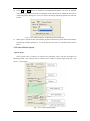
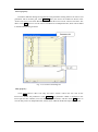
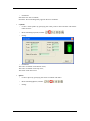
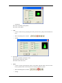
1
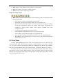
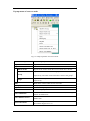
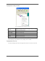
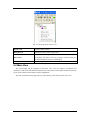
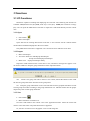
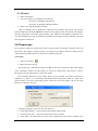
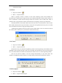
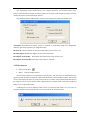
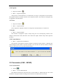
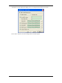
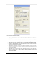
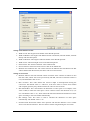
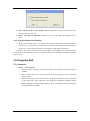
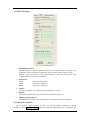
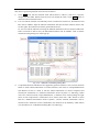
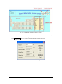
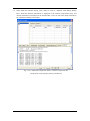
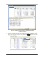
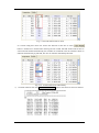
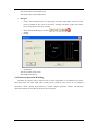
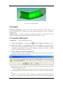
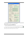
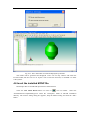
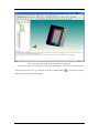
MCAM 4.8 User Manual FDS Team Content MCAM 4.8 User Manual .......................................................... 1 Content ...................................................................................................................................... 2 1 Introduction ........................................................................... 1 1.1 Background ......................................................................................................................... 1 1.2 Main Functions ................................................................................................................... 1 2 User Interface ....................................................................... 1 2.1 Menu ................................................................................................................................... 2 File .................................................................................................................................... 2 Edit .................................................................................................................................... 3 View .................................................................................................................................. 3 Preprocess ......................................................................................................................... 3 Convert .............................................................................................................................. 4 Modeling ........................................................................................................................... 4 Modify............................................................................................................................... 4 Tools .................................................................................................................................. 5 Windows ........................................................................................................................... 5 Help ................................................................................................................................... 5 2.2 Toolbar ................................................................................................................................ 5 File .................................................................................................................................... 5 Display Model ................................................................................................................... 5 Standard View ................................................................................................................... 5 Section View ..................................................................................................................... 6 Modeling and Modify ....................................................................................................... 6 Preprocess and Convert ..................................................................................................... 7 2.3 Tree View ............................................................................................................................ 7 Icons of tree node .............................................................................................................. 8 Pop-up menus of root tree node ........................................................................................ 9 Pop-up menus of group tree node ................................................................................... 10 Pop-up menus of entity tree node.................................................................................... 11 Pop-up menus of tree view .............................................................................................. 11 2.4 Main View ......................................................................................................................... 12 Popup menu in main window:......................................................................................... 13 2.5 Information view ............................................................................................................... 14 3 Functions ............................................................................ 15 3.1 I/O Functions..................................................................................................................... 15 3.1.1 Open ....................................................................................................................... 15 3.1.2 Import ..................................................................................................................... 15 3.1.3 Save ........................................................................................................................ 15 3.1.4 Export ..................................................................................................................... 16 3.2 Preprocess ......................................................................................................................... 16 3.2.1 Scale ....................................................................................................................... 16 3.2.2 Heal ........................................................................................................................ 17 3.2.3 Check ..................................................................................................................... 17 3.2.4 Decompose ............................................................................................................. 17 3.2.5 Reconstruct............................................................................................................. 18 3.2.6 Explode .................................................................................................................. 19 3.2.7 Glue ........................................................................................................................ 19 3.2.8 Split ........................................................................................................................ 19 3.2.9 Count Surfaces ....................................................................................................... 19 3.3 Conversion (CAD – MCNP) ............................................................................................. 19 3.3.1 User Interface ......................................................................................................... 19 3.3.2 Conversion parameter setting ................................................................................. 21 3.3.3 Global Config Setting ............................................................................................ 22 3.3.4 Note: Problem of Spline Surfaces .......................................................................... 24 3.3.5 Typical problems and solutions .............................................................................. 24 3.4 Inversion (MCNP-CAD) ................................................................................................... 24 3.4.1 User Interface ......................................................................................................... 24 3.4.2 Typical problems and solutions .............................................................................. 25 3.5 Properties Edit ................................................................................................................... 25 3.5.1 Summarize ............................................................................................................. 25 3.5.2 Graphic Property .................................................................................................... 26 3.5.3 MCNP Property ...................................................................................................... 27 3.5.4 Material Card Edit .................................................................................................. 27 3.5.5 Source/Tally Property............................................................................................. 34 3.6 Geometry Modeling .......................................................................................................... 37 3.6.1 Create Primitive Unit ............................................................................................. 37 3.6.2 Boolean Operation Modeling ................................................................................. 41 3.6.3 Model Modification ............................................................................................... 42 3.6.4 Void modeling ........................................................................................................ 47 4 Example .............................................................................. 48 4.1 Load the CAD model ........................................................................................................ 48 4.2 Preprocess the CAD model ............................................................................................... 49 4.3 Edit the properties ............................................................................................................. 51 4.4 Convert the model ............................................................................................................. 51 4.5 Invert the generated MCNP file. ....................................................................................... 52 4.6 Invert the installed MCNP file. ......................................................................................... 53 5 Service and Support ........................................................... 56 1 Introduction 1.1 Background Welcome using MCAM. MCAM (Multi-Physics Coupling Analysis Modeling Program) is developed by FDS Team, China. As an integrated interface program between modern CAD systems and Monte Carlo radiation transport simulation codes (SuperMC, MCNP, TRIPOLI, Geant4, FLUKA, PHITS, etc.), MCAM not only realizes the bi-directional conversion between CAD models and Monte Carlo calculation files, but also integrates the functions of creation, pre-processing, analysis and edition for CAD models. With MCAM, users are free to use the CAD models created by commercial CAD systems that support neutral CAD file formats such as STEP. With the help of MCAM, users are able to load the existing CAD models created by commercial CAD systems or create simple CAD models directly, then convert them into MCNP calculation files. Contrarily, users also can invert the existing MCNP calculation files into CAD models, then check or modify the models in MCAM. More information please visits the website of FDS Team: www.fds.org.cn/en/. 1.2 Main Functions MCAM includes five basic function modules. Some extended modules for special use have been developed, such as reconstruction of the human body model based on 2D CT images and the visualization of MCNP and TRIPOLI calculation results. These extended modules are integrated in special editions of MCAM. (1) Preprocessor: Include the necessary functions for CAD engineering model pre-processing. (2) Converter: Implement the converting function from CAD models into MCNP completed calculation files. (3) Inverter: Implement the reverse converting function from MCNP calculation files into CAD models. (4) Analyzer: Implement the visualization and interactive editing of CAD models, including geometry information and neutronics properties. (5) Creator: Implement the CAD model geometry constructing functions, including primitive shapes creation, Boolean operation and geometry transformations, etc. 2 User Interface Fig.2-1 shows the organization of the main window elements, which include Menu, Toolbar, Tree View, 3D Graphic View. Information Window and Property dialog. FDS Team, China -1- Fig.2-1 MCAM User Interface 2.1 Menu File New Create a new empty window. CAD models can then be imported into the new scene via the File/Import button, and the MCNP input files can be read via the Tool/Read MCNP. Open Launch the file browser. Use this to find and open a FDS format CAD model file. Close Close the current window. If the model is modified, MCAM prompts to save or discard the changes. Save Save the model under the current file name. Save as Save the current model under a new file name, or save the graphic view as a tiff image file. Import Import CAD models into the current window. The STP (STEP) and SAT, IGES format are supported. Export Export the selected entities to a model file in SAT, STP or IGES format. Print Print the contents in the current window. Print Preview Preview the printing effect. Print Setup Setup the printing parameters. Exit Quit MCAM. FDS Team, China -2- Edit Undo Undo the operation of geometry modify Redo Redo the operation of geometry modify Select Solid Set the selection mode of solid. Select Face Set the selection mode of surface. Choose a surface on an entity, the information will be calculated and displayed in the information view. Select Edge Set the selection mode of edge. Select By Single Click Select entities by clicking left button of mouse. Select By Windows Use mouse to drag a rectangle. The entities in the rectangle will be selected. Delete Selection Delete the selected entities. View Display Model Set the rendering modes, such as Shaded, Triangulated, Hidden Line and Wireframe. Standard View Select the predefined standard orthographic and isometric views. Camera Camera that could be manipulated to change the current view of the model. The camera operations include Orbit, Pan and Zoom in/out. Topology Tree Show/hide the tree view control on the left side. Information Windows Show/hide the information windows at the bottom of MCAM. Status Bar Show/hide the status bar. Property Show/hide the property dialog box on the right side. Orthographic Use Orthographic mode to display the model. Perspective Use Perspective mode to display the model. Shadow Show/hide the shadow of model. XY section XZ section YZ section Toolbar Show/hide Cutting Planes, each button shows a locatable cutting plane in one of the three major axis directions and show it in the scene. Show/hide each toolbar on the framework. Preprocess Heal Implement the healing function to fix the imported models, which are created in other modeling systems, in order to eliminate the geometry error and make them usable for conversion. Scale Enlarge or reduce selected entities proportionally. Decompose Decompose the complex entity into several simpler and smaller ones by adding auxiliary surfaces. Reconstruct Reconstruct the model, in order to eliminate the tiny gaps and overlaps between the neighbouring entities. The original model will be decomposed into compound of several convex entities, which could be exploded into FDS Team, China -3- several component entities. Check Check and fix the interferences between entities. Explode Break a compound entity into several component entities. Glue Combine several entities together as an integrated entity, which is opposite to explode function. Split Split a solid using a selected surface of its nature surfaces. Lost Particle Draw the trace of a particle that could help to find the position of lost particles according to the MCNP calculation result file. Count Surface Count the number of surfaces of the selected entities. Convert Write MCNP Launch the CAD-MCNP conversion module and convert the current CAD model into a MCNP input file. Read MCNP Launch the MCNP-CAD conversion module. Read the selected MCNP input file, invert it into a CAD model and display it. Modeling Line Create a straight line by specifying two coordinates. Rectangle Create a rectangular polyline by specifying two corner coordinates. Arc Create an arc by specifying three coordinates. Block Create a block by specifying the two diagonal coordinates. Cylinder Create a solid cylinder by specifying the center point for base and other end and the radius for base. Sphere Create a sphere by specifying the center coordinate and radius. Cone Create a solid cone by specifying the center point for base, peak point and radius for base Torus Create a torus by specifying the center, torus radius and tube radius. Ellipse Torus Create an ellipse torus by specifying the center, minor radius, normal, and major radius and torus radius. Hexagon Create and hexagonal prism by specifying the radius and height. Modify Union Combine selected solids by Boolean union operation. Subtraction Combine selected solids by subtraction, namely subtract solids from other solids. Intersection Create composite solids from the intersection of two or more solids. Move Displace entities a specified distance in the specified direction. Rotate Rotate entities around a base point. Copy Duplicate entities. Rectangle Array Create multiple copies of entities in a rectangle pattern. Polar Array Create multiple copies of entities in a polar pattern. Slice Slice entities with a plane, cylinder or sphere. FDS Team, China -4- Create a mirror image copy of entities. Mirror Tools Options Modify application settings, including the display effect, appearance, file format and interaction. Settings Modify the important parameters for model conversion. Such as the precision used by conversion and the format of output file. Windows Arrange windows in horizontal, non-overlapping tiles. Title Help About Display the licenses information of MCAM. Version Display the version information of MCAM. Help Launch the MCAM user manual file. 2.2 Toolbar File File New: Create a new empty window. Files can then be imported into the new scene via the File-Import button on menu. File Open: Locate and open a FDS format CAD File. File Save: Save the model under the current file name. Print: Print the contents of the current view. Import: Import CAD models into the current window. The STP (STEP) ,SAT and IGES format are supported. Export: Export the selected entities to a model file in SAT, STP or IGES format. Display Model Shaded: Set the rendering mode to Shaded. Triangulated: Set the rendering mode to Triangulated. Hidden-line: Set the rendering mode to Hidden-line. Wireframe: Set the rendering mode to Wireframe. Select by Solid: Use the mouse to select solid entities. Select by Surface: Use the mouse to select a surface. Select by Edge: Use the mouse to select an edge. Select by Window: Define a window to select entities. Standard View FDS Team, China -5- Top: Set the camera in the active view to the top of the object. Bottom: Set the camera in the active view to the bottom. Left: Set the camera in the active view to the left. Right: Set the camera in the active view to the right. Front: Set the camera in the active view to the front. Back: Set the camera in the active view to the back. Isometric: Set the camera in the active view to show the object in isometric position. Zoom: Use the mouse to interactively change the camera field (Zoom in or out). Zoom to Extents: Reset the camera to view the entire scene. Zoom to Window: Use the mouse to define a new camera view field. Orbit: Use the mouse to interactively orbit the camera. Pan: Use the mouse to interactively pan the camera in the active view. Test Performance: Animate the model in the scene to test the performance. Display the information about the performance (in frames/second) achieved. Section View Create Cutting Plane: Each button shows a locatable cutting plane in one of the three major axis directions and inserts it into the scene. A reference range of the whole entities is given in a dialog. At the same time, an edit box is given below with a default value which can be changed before clicking the <ok> button. Clicking again removes the cutting plane. Holding Down [SHIFT] and clicking on the button while the cutting plane is active removes the handles from the plane. Use the mouse to interactively rotate/pan the cutting plane to see the sections of models in various planes. Modeling and Modify Blocks: Create a block. Cylinder: Create a cylinder. Sphere: Create a sphere. Cone: Create a cone. Torus: Create a torus. Ellipse Torus: Create an ellipse torus. Hexa: Create a hexagonal prism. Union: Combine the selected solids by addition. Subtraction: Combine selected solids by subtraction, namely subtract solids from other solids. Intersection: Create composite solids from the intersection of two or more solids and remove the areas outside of the intersection. Move: Displace entities by a specified distance in a specified direction. Rotate: Rotate entities round a base point and an axis. Copy: Duplicate entities. Rectangle Array: Create multiple copies of the selected entities in a rectangle pattern. FDS Team, China -6- Polar Array: Create multiple copies of entities in a polar pattern. Slice: Slice entities with a plane, cylinder or sphere. Mirror: Create a mirror image copy of entities. Preprocess and Convert Heal: Heal the imported models created in other modeling systems into MCAM in order to make them usable. · Scale: Enlarge or reduce selected entities proportionally. · Decompose: Decompose the complex entity into several simply ones. · Reconstruct: Reconstruct the model, in order to eliminate the tiny gaps and overlaps between the neighbouring entities. The original model will be decomposed into compound of several convex entities, which could be exploded into several component entities. · · · · · Check: Check the interference among the entities. Explode: Break a compound entity into several component entities. Glue: Combine several entities together as an integrated entity. Write MCNP: Convert the CAD model in the active view into a MCNP input file. Read MCNP: Load a MCNP input file, convert it into a CAD model and display the model in the active view. 2.3 Tree View Click the View /Topology Tree button on the menu will display the tree view in the left side of the main frame. Each node on the tree represents a group of entities or one entity in the main view. If a node is selected, corresponding entities will be highlighted in the main view. Different node icons represent different states of the group and entity, for example, <Hidden> or <Shown>. The nodes in the tree view include root node, group node and entity node. When click the right button of mouse on nodes, different pop-up menus will appear and the relevant processing functions will be supplied. Three kinds of pop-up menus corresponding to three kinds of nodes will be introduced in the following. FDS Team, China -7- Fig. 2.3-1 Feature of tree view. Icons of tree node The icon of root tree node and group tree node, which is in folded state. The icon of root tree node and group tree node, which is unfolded state. All the entities under the group tree node are hidden. The entity in <Shown> state. The entity is selected. The entity in <Hidden> state. The entity has been successfully converted into cell description of MCNP. The entity has not been converted into cell description of MCNP successfully. The format of the entity node in the tree view is <xxx(yyy)>. <xxx> is the serial number of entity list. If the model is reverted from MCNP file, <yyy> has meaning that represent the cell number in MCNP file. FDS Team, China -8- Pop-up menus of root tree node Fig. 2.3-2 Pop-up menus of root tree node Add New Group Add a new group node under the root tree node. Import Entities Import the entities under the root tree node. Export Entities Whole model Export all the entities under the root tree node into CAD file. Export the entities under the group node into CAD file Group Single respectively. The name of the CAD file is same as the group,s. Export each entity under the root tree node into a CAD file respectively. Hide Hide all the entities under the root tree node. Redisplay Redisplay the hidden entities under the root tree node. Expand Unfold all the group tree nodes. Fold Fold all the group tree nodes. Select All Entities Select all the entities under the root tree node, including the entities in hidden state. Select Entities in View Select the entities under the root tree node which are not in hidden state. Reset cell Number Re-sort the sequence number of entities under the root tree node. The number begins from <1>. FDS Team, China -9- Pop-up menus of group tree node Fig. 2.3-3 Pop-up menus of group tree node Select Group Select all the entities under the group tree node. When there are hidden entities included, a dialogue box will be displayed. Yes Display and select the hidden entities. No Do not display and select the hidden entities. Export Entities Group Single Export the entities under the group node into a CAD file. The group name is used as CAD file name. Export each entity under the group node into CAD file respectively, which , Import Entities are saved in a folder whose name is the group s. Import a CAD file into the selected group. Rename Rename the selected group. Delete Group Delete all the entities under the selected group, including the group tree node. Hide Group Hide all the entities under the group. Display Group Display all the entities under the group. Display Singly Display only the selected group and hide the other groups. Note: If the selected group is in hidden state, only <Display Group> and <Display Singly> items are available. FDS Team, China - 10 - Pop-up menus of entity tree node Fig. 2.3-4 Pop-up menus of entity tree node Property Display the property dialog box that supports editing of graphic and MCNP related properties. Export Entity Export the selected entity into a CAD file. Delete Entity Delete the selected entity. Hide Entity Hide the selected entity. Display Entity Display the selected entity. Rename Rename the selected entity. Move To Group Move the selected entity into another group. Note: If the entity is in the hidden state, only <display> item is available. Pop-up menus of tree view The menu will display when click mouse right button in the tree view but not on tree node. FDS Team, China - 11 - Fig. 2.3-4 Pop-up menus of tree view Deselect All Deselect all the entities. Refresh Item Refresh the entity to the original state. Show State Show that the entity can be converted into cell description successfully. The state is saved as a property of entity which can be checked when the entity is loaded again. Back Ground Color Set the background color. 2.4 Main View The CAD model will be displayed in the main view. Users can observe, manipulate and modify the CAD model with different display mode. The entities in the model could be selected by mouse click and the selected entities will be highlighted. The user could launch the popup menu by right clicking mouse button in the main view. FDS Team, China - 12 - Pop-up menus in main window: Fig. 2.3-5 Pop-up menus in main window Exit Cancel the selection and exit the selection mode. Pan Use the mouse to interactively pan the camera in the active view. Orbit Use the mouse to interactively orbit the camera. Select Body Set the selection mode of solid. Select Face Set the selection mode of surface. Chooses a surface and obtain the equation and parameter in the information view. Select Edge Set the selection mode of edge. Zoom Select Reset the camera to view the selected entities. Zoom Windows Use the mouse to define a new camera view field. Visibility Set the visibility of objects in the main view, including vertices, edges, faces, lights. Select to display the capping plane or the capping line when using Cutting Plane. Rendering mode Set the rendering modes, such as Shaded, Triangulated, Hidden Line and Wireframe. Standard View Select the predefined standard orthographic and isometric views. XY section YZ section Show/Hide the X, Y, Z direction cutting planes. XZ section FDS Team, China - 13 - Import Entity Import entities into the current view. Export Entity Export the selected entities into a CAD file. Hidden Hide the selected entities. Delete Delete the selected entities. Property Open up the property dialog box. Display the properties of the selected entity. 2.5 Information view The information view is in the bottom of frame. It is used to display the basic information, e.g., the equation and parameter of surface, executive outcomes of functions. Fig. 2.5-1 Information view FDS Team, China - 14 - 3 Functions 3.1 I/O Functions MCAM is capable of loading and displaying the CAD file. The following file formats are available: FDS(MCAM solid file),SAT( ACIS object solid file),STEP( ISO standard exchange file). User can open the FDS format CAD file or import the CAD model directly into the current view. 3.1.1 Open File Toolbar Menu: File/Open Open and load an existing FDS format CAD file. A new window will be created and the model will be loaded and displayed in the new window. Only FDS format CAD file is supported. User can load several CAD files at one time. 3.1.2 Import Menu: File/Import Tree View: Root tree node/Popup menu/Import Group tree node/Popup menu/Import Main View: Popup menu/Import Entity Import the CAD model into the current active view, and then a message box appears. User can choose whether to keep the group information of the imported entities. Yes: Create a new group tree node in the tree view control, add all the entities of this CAD file into the group and use the file name as the group name. No: Keep the group information in the CAD file that has been grouped and edited. Create several group tree nodes according to the group information in it. Add the entities into the groups respectively base on their group attributes. 3.1.3 Save File Toolbar Menu: File/Save or File/Save as Save the CAD model in the current view to the appointed location. Under the current file name or a new file name. Only FDS file format is supported. Or, use Save as menu to save the graphic view as a tiff image file. FDS Team, China - 15 - 3.1.4 Export Menu: File/Export Tree View: Root tree node/Popup menu/Export Group tree node/Popup menu/Export Group tree node/Popup menu/ExportEach Main View: Popup menu/Export Entity A file save dialogue box is displayed to export the CAD model in the current view into the selected model file. The SAT, STEP file format are both supported. The SAT format will keep the necessary information, such as the group attribute, color, material, neutron/photon importance, etc. As for the STEP format, only the geometry information will be kept, the group attribute, color and other properties will be lost. 3.2 Preprocess The preprocess functions include Scale, Heal, Overlap Check, Decompose, Explode, Glue and Reconstruct. The purpose of preprocessing is to prepare an available CAD input model from the CAD engineering model before converting it into a MCNP input file. 3.2.1 Scale Preprocess Toolbar Menu: Preprocess/Scale The engineering CAD models usually use mm as the unit of dimension. But many Monte Carlo calculations models use cm instead. So when the engineering CAD model is read by MCAM, the users should enlarge or reduce the model. The maximum dimension of the model which can be smoothly converted by MCAM is 10000(cm), i.e. The X, Y, Z of the model should be inside the range from -5000 to 5000. If the model cannot be converted successfully, please check the size of the model, and use the scale function to reduce the size of it. A dialog box appears when users use scale function. Scale Whole Model: All the entities in the model will be scaled. Scale Selected Cells: Only the selected entities will be scaled. Scale Ratio: The dimension unit ratio of the engineering CAD model to Monte Carlo FDS Team, China - 16 - calculations model. 3.2.2 Heal Preprocess Toolbar Menu: Preprocess/Heal When a geometry model is created in some other modeling system and translated into MCAM, such a model may be imprecise due to the inherent limitations of their parent systems, or due to limitations of data transfer through neutral file formats such as STEP. This leads to problems such as gaps between entities, and the absence of topology connectivity information. The Heal function can be used to detect and correct the error in CAD models in order to make them usable. Heal function may not be able to correct all of the problems that may exist in a model, but it will detect and correct a large percentage of them. A Message box appears when users select to heal CAD models. Users can choose to heal all the entities in the model (Yes) or just heal the selected entities (No). 3.2.3 Check Preprocess Toolbar Menu: Preprocess/Check Interferences may exist between neighboring entities in the engineering CAD model, but are forbidden by MC particle transport codes such as MCNP. The interferences will cause the particle loss. The check function will detect and eliminate this kind of errors in CAD engineering models. The user can choose whether to fix the overlaps automatically or only show them. The numbers of neighboring entities that have overlaps will be printed in the information window. 3.2.4 Decompose Preprocess Toolbar Menu: Preprocess/Decompose FDS Team, China - 17 - The engineering CAD model always has complex geometry and contains many curve surfaces. MCNP limits the length of cell description. So an entity with complex geometry has to be decomposed into several small simple entities. This function helps to add auxiliary surfaces to decompose the model into smaller ones. Auto-Split: Decomposed the entity, choose to explode its component lumps into independent entities or glue them together as an integrated entity. Recursively: Choose whether to decompose the entities recursively or not. Max Decompose Level: The depth of recursive decomposition. Decompose whole model: Decompose the whole model in the current view. Decompose selected model: Decompose the entities in selection. 3.2.5 Reconstruct Preprocess Toolbar Menu: Preprocess/Reconstruct The reconstruct function is developed for two purposes. The first one is to eliminate the tiny gap and overlap between the adjacent entities that should have same boundary surface. The second one is to decompose the entity by using of the surfaces on entities. The reconstruction decomposes the entity into set of convex entities. Then explode function could be used to break the compound entity into its component entities. A Message box will be displayed when select to reconstruct the model. User can select to reconstruct all the entities in the current view or reconstruct the selected entities. FDS Team, China - 18 - 3.2.6 Explode Preprocess Toolbar Menu: Preprocess/Explode After process of decomposition or reconstruction, an entity is composed of several entities. The explode function can help to break it into component entities. This function is designed only to explode the selected entities. 3.2.7 Glue Preprocess Toolbar Menu: Preprocess/Glue Glue is opposite to Explode, which is to compose the selected entities as a whole one. 3.2.8 Split Menu: Preprocess/Split This function is designed to split an entity using one of its decomposing surfaces. First change to FACE select mode, and select a face. Then click <Split> and the entity will be split into two parts. 3.2.9 Count Surfaces Menu: Preprocess/Count Surfaces This function is developed to count the surfaces of selected or whole entities. A Message box will be displayed when select to count the surfaces. User can select to count the surfaces of all the entities in the current view or just the selected entities. 3.3 Conversion (CAD – MCNP) 3.3.1 User Interface Toolbar Menu: Convert /Write MCNP This function realizes the conversion from a CAD model to a MCNP input file. The CAD model has to be preprocessed according to the actual state of model before conversion. FDS Team, China - 19 - A dialog box will be displayed helping users to set the parameters before conversion. Click <More> button to see more settings shown in below figure. FDS Team, China - 20 - 3.3.2 Conversion parameter setting Run in stand-alone process: Call an independent background application to complete the conversion. Whole model & selected cells: Convert the whole model in current view or just the selected entities. Set cell No. from: Assign the starting number of cells in the MCNP input file. Start surface No.: Assign the starting number of surface equations in the MCNP input file. Output File: The location and name of the generated MCNP input file. Users can change them by the browser button on right side. With Material: The location and name of the material specification file. Users can change them by the browser button on right side. This file may be generated by the Material Card Edit function of MCAM. With SDEF: The location and name of the source specification file. Users can change them by the browser button on right side. This file may be generated by the Source Card Edit function of MCAM. With TALLY: The location and name of the tally specification file. Users can change them FDS Team, China - 21 - by the browser button on right side. This file may be generated by the Tally Card Edit function of MCAM. Output volume card: Whether to generate the volume card. Floating format: The format of the float value expression in the MCNP file. Scientific format: The format of the scientific value expression in the MCNP file. Generate void space: Whether to generate the void space descriptions. If the CAD model already contains the void space entities. This option need not to be checked. Generate reflect surface: Add two reflecting surface numbers in the void space descriptions to describe the model with reflect surfaces. Input the surface equations of two reflecting surfaces. The equation description of a surface can be obtained using Face Selection function. Void Type # CellNo: Use boxes to bool subtract (#) the cell no.; # CellDesc: Use boxes to bool subtract (#) the cell description; Complement: Eliminate the <#> character in the void cell description. This type is recommended; Optimized: The optimized description of the <complement> type. This type usually does not work for complex geometry. Cell Limit: Change the cell limit and surface limit to adjust the length of void cell description, to avoid that the length of void cell description exceed 1000 which is the limit of MCNP. The length will increase if the value is enlarged. Surface Limit: Change the cell limit and surface limit to adjust the length of void cell description, to avoid that the length of void cell description exceed 1000 which is the limit of MCNP. The length will increase if the value is enlarged. Min Cell Size: The minimum size of void cell. 3.3.3 Global Config Setting Menu: Tools / Setting The configurations contain the format of the MCNP files and related parameters for conversion. FDS Team, China - 22 - Setting of MCNP files format: Width of cell: The length of cell number in the MCNP input file. Width of Blanket: The length of the blank between cell number, material number, material density and cells description. Width of Material: The length of material number in the MCNP input file. Width of line: The limit length of line in the MCNP input file. Float Format: The format of the float value in MCNP file. Science Format: The format of the science value in the MCNP file. Minimal abs & Maxima abs: The values between the Minimal abs and Maxima abs that will be defined with float format, the others will use science format. Setting of conversion: Minimal Volume: The limit minimal volume of model. If the volumes of entities are less than this value, which will not be processed by MCAM, The unit of minimal volume is cm3, and the default value is 10-6. Max recursion: This value defines the recursive depth of decomposition during the conversion. The default value is 5. However, if the users want to convert some models with complex geometry they should increase the value of max recursion. Max Bound Box: This value defines the dimension of outer space. For example, if the value is 3000, it means the outer space is from -1500 to 1500 in the direction of X, Y, Z axis. The default value is <0>, which means MCAM will calculate the dimension of outer space according to the CAD model automatically. Box Enlarge scale: The value is used to calculate the dimension of outer space automatically. The default value is <4>. Position Delta & Direction Delta: If the position and direction distance of two similar faces is less than the tolerance. The two surfaces will be merged during the conversion. FDS Team, China - 23 - 3.3.4 Note: Problem of Spline Surfaces This function reminds users if there are spline surfaces in the models to be converted. A Message box will be displayed to prompt users whether to continue. User can press <Yes> to continue or press <No> to cancel the conversion. It is suggested that the conversion be cancelled and some operations be done to treat these spline surfaces depending on manual implementation as MCAM4.8 cannot deal with spline surfaces and errors may occur in MCNP file obtained. 3.3.5 Typical problems and solutions Conversion cannot be finished correctly for some complex models. Solutions: It is suggested that the automatic decompose function of MCAM4.8 for the complex models be done firstly. As user like, you can use the commercial CAD software to decompose manually, then import to MCAM. When using MCNP program to calculate some MCNP input files obtained by conversion function of MCAM4.8, the MCNP calculation result file showed that some particles were lost. Solutions: Firstly, check that all the entities were converted successfully (no <fail> characters in the generated MCNP input file). Check whether there is tangent of plane and cylinder in the original CAD models which is suggested to be manual decomposed. If you still have any questions, please contact to [email protected]. 3.4 Inversion (MCNP-CAD) 3.4.1 User Interface Toolbar Menu: Tool /Read MCNP Opposite to conversion function, the inverter of MCAM realizes the conversion from a MCNP input file to a CAD model and visualized it. The current version of MCAM supports the cell card, surface card, material card and the description of repeated structure is also available. for example the <U> card, <Fill> card, <TR> card , <Like m But> card etc. The current version of MCAM can not check and fix the errors in the input file, so please make sure that the file does not have any errors. When a MCNP input file is chosen, a dialog box for parameter setting will be displayed. FDS Team, China - 24 - Show inverted cells in new model: MCAM will create a new model and show the inverted cells in a new view. Invert void cells (no material): Whether invert the void space cells (Material No. is zero). 3.4.2 Typical problems and solutions When a MCNP input file is very complex, for example, thousands of repeated structure contained in it with<lat>and <u>card, the inversion process of MCAM may collapse in the process of inverting as the memory consumption of MCAM more than 2G. Solutions: The reason is that the memory consumption of 32bit application is allowed at most 2G in the Microsoft operating system. It is suggested that manual splitting of the MCNP input file be done firstly. 3.5 Properties Edit 3.5.1 Summarize Menu: View /Property · When an entity is selected, click the <property> item in right-click pop-up menu is enabled. · When a entity node in tree view is selected, click the <property> item in right-click pop-up menu. · When choose the properties edit function, the property dialog box will be displayed on the right side of the framework. The properties include the graphic property, MCNP property and Source/Tally property. User can display, edit and change the related properties of models. FDS Team, China - 25 - 3.5.2 Graphic Property Fig.3.5.2-1 Graphic property Entity Information: Display the type of selection, such as body, surface and edge. When a group node in the tree view is selected, the number of entities in this group will be displayed. Display the bound box of selection if the selection is body. When a group node in the tree view is selected, the bound box of entities in this group will be displayed. Group Information: Display the group and entity name when the group node or entity node in the tree view is selected. Color: Display and assign the color information of the selected entities. Users must click <Apply> button to change the assignment. Transparence: Change the transparence of the selected entities. Users can use the slide control to modify the value of transparence. FDS Team, China - 26 - 3.5.3 MCNP Property Fig. 3.5.3-1 MCNP property Material Information: Material Number: Assign the material number on the selected entities or groups. This assignment can be automatically entered into force without clicking <Apply> button. Density: Assign the density on the selected entities or group. Do not forget to click <Apply> button to activate the assignment. Importance: IMP P: IMP N: IMP e: The photon importance. The neutron importance. The electron importance. Volume: Calculate and display the volume of the selected entity or entities. Remark: Add remark information in the cell description behind the symbol <$>. Additory MCNP Property: Add additional information after the importance information in the cell description. 3.5.4 Material Card Edit By the material editing function the users can edit the material properties for MCNP calculation. Click Edit Material Card button, the material editing dialog box is displayed. The FDS Team, China - 27 - main flow of generating material card is shown as follows: 1) Click Add button, add new material name whose format is <Mxxx>, and xxx is a positive integer less than 5000. Double click the item can modify the name. Click Delete button to delete the selected material name. 2) User can edit the material card manually. Select a material in left list box, the Material Card Box will be editable. Input the material information and then click the material name in left list box again, the material card will be generated and saved. Or, user can edit the material card using the Material Information Process System of MCAM. Select a material in left list box, the Edit Material button will be editable. Click it and the material choosing dialog box will be pop up. 3) Fig. 3.5.4-1 Material Card Editing Dialog Box Compound/ Elements and Mixture are supplied to generate material. Users can click elements button to check related information of certain elements, click items in Compound/Elements and Mixture list box to check or edit the related information of certain compound and mixture(see introduction of <Material Information Process System> as following). When users have selected certain Compound/Elements ,or Mixture items with inputting the right , ratios of each composition s volume(from 0% to 100%), then click <OK> button to return back the <Material Information Process System>, and the material information will be selected in the <Selected> list box. Meanwhile, new material can be added by <Add> button (see introduction of <Add Material Dialog Box >as following ). FDS Team, China - 28 - Fig. 3.5.4-2 Material Information Process System 4) In addition, the composition of material and isotopes of element have been determined, if users want to check and edit the compositions of the material or isotope ratios of elements. Click Composition button to check and edit the relevant elements and ratios. Fig. 3.5.4-3 Material Information Dialog Box FDS Team, China - 29 - Fig. 3.5.4-4 Composition Dialog Box 5) Well, when button has been clicked, new materials(Compound/ Elements and Mixture) can be added and edited in this Dialog Box. When users choose item <Add Compound/ Elements >,element and isotope can be selected ,and Compound/ Elements & Mixture can be selected when users choose item <Add Mixture>. Meanwhile, other information of the new material like Name , Mass ,Melting etc can be setting in this Dialog. Then, users can click the <add> button to add the new material to the material database. Of course, users can also reselect new material by using the<Reselect> button and cancel the operation by using the<Exit> button. Fig. 3.5.4-5 Add Material Dialog Box FDS Team, China - 30 - 6) When finish the material editing, Click <OK> to return to <Material Card Editing Dialog Box>. Relevant material information is displayed in the material composition table, and nuclide information is displayed in the nuclide table. Users can edit some detail information for calculation with these two tables. Fig. 3.5.4-6 <Material Composition Table> contains Composition ID, Composition Name, Symbol, Density and Percent. FDS Team, China - 31 - Fig. 3.5.4-7 Nuclide Table contains Nuclide ID, Nuclide Number in MCNP, Lib, Density and Percent. a) b) There are four modes to show the density include nuclide density, nuclide density percent, nuclide mass and nuclide mass percent. Users double clicks Density item, pull-down menu will be supply four options. Fig. 3.5.4-8 Edit material density in union Choose material libs, and user can edit them in union or individually. FDS Team, China - 32 - Fig. 3.5.4-9 Edit material libs in union. It is worth noting that when user choose the function to edit libs in union, button is needed to be clicked after choosing the lib wanted. MCAM would read lib files to screen nuclides needed automatically, the nuclides not contained in the lib would be chosen in other libs automatically by MCAM, but user can edit libs individually after that. 7) Fig. 3.5.4-10 Edit material libs individually. Generate material card using Generate Material Card button. The format is shown as follows: FDS Team, China - 33 - 8) 9) Click OK and Save buttons on <Material Card Editing Dialog Box> can save the material information generated as material card. Material name and density are added into the list box of MCNP property dialog box. Users can choose and assign material properties onto relevant entities. Fig. 3.5.4-11 Material list box in MCNP property dialog box When open or import models with material properties, MCAM can parse material and density information included. Besides, it can read material card direct in standard format shown above. 3.5.5 Source/Tally Property Special Target: Some special cells or surfaces are selected for generating source and tally description of MCNP input file. Users specify cells or surfaces in the model as special targets with sign * (for cell) or ^ (for surface). Fig. 3.5.5-1 Source/Tally property FDS Team, China - 34 - Source property: Parameter definition dialog box supplies the main parameters editing function for source card generation. Fill in the data grid, click Generate button, the source card edited are shown in the <Source Card Text> box below. Besides, users can edit the source card in <Source Card Text> box direct. Click Save button to save the source card edited as an independent file, which can be added in the MCNP input file generated. Fig. 3.5.5-2 Source edit dialog box Tally property: Click New button to add a new tally, and select <Value> node in the tree view on the lower-left to define the parameters. Click Generate, the parameters edited is displayed in the lower-right text box. Besides, users can edit the tally card direct, and then click Save button to save the tally card as an independent file, which can be added in the MCNP input file generated. FDS Team, China - 35 - Fig. 3.5.5-3 Tally card definition dialog box Fig. 3.5.5-4 Tally parameter editing FDS Team, China - 36 - Fig. 3.5.5-5 Parameter editing box 3.6 Geometry Modeling Similar as the general CAD systems, MCAM provide the geometry modeling function. Users can firstly create primitive units, and then use bool operations and modification function to create more complex geometry models. 3.6.1 Create Primitive Unit Users can create some primitive units like block, cylinder, sphere, cone, torus and hexagonal prism. Block · Create a block by specifying the two diagonal coordinates. · Menu: Modeling/Block; Toolbar: · Dialog: FDS Team, China - 37 - · Parameters: Start Point: the first coordinate; End Point: the second diagonally opposite the first coordinate. Cylinder · Create a solid cylinder by specifying the center point for base and other end and the radius for base. · Menu: Modeling/Cylinder; Toolbar: · Dialog: · Parameters: The center coordinate of the bottom circle; The center coordinate of the top circle; The radius of the base circle. Sphere · Create a sphere by specifying the center coordinate and radius. · Menu: Modeling/Sphere; Toolbar: · Dialog: FDS Team, China - 38 - · Parameters: The center coordinate of the sphere; The radius of the sphere. Cone · Create a solid cone by specifying the center point for base, peak point and radius for base. · Menu: Modeling/Cone; Toolbar: · Dialog: Parameters: The center coordinate of the base circle; The peak point of the base circle; The radius of the base circle. Torus · Create a torus by specifying the center, torus radius and tube radius. The axis of the torus is parallel to the z-axis of the active working coordinate system. · Menu: Modeling/Torus; Toolbar: · Dialog: FDS Team, China - 39 - · Parameters: The center coordinate of the torus; The minor radius of the torus.; The major radius of the torus. EllipseTorus · Create an ellipse torus by specifying the center, minor radius, normal, and major radius and torus radius. · Menu: Modeling/EllopseTorus; Toolbar: · Dialog: · Parameters: The rotate center coordinate of the ellipse torus; The rotate Axis Normal of the ellipse torus; FDS Team, China - 40 - The minor radius of the ellipse torus; The major radius of the ellipse torus. Hexagon · Create and hexagonal prism by specifying the radius and height. The axis of the prism is parallel to the z-axis of the active working coordinate system. The center point of the prism is the zero crossing. · Menu: Modeling/Hexagon; Toolbar: · Dialog: · Parameters: The inner radius of the prism; The height of the prism. 3.6.2 Boolean Operation Modeling Booleans are used to unite or intersect two or more solid bodies, or to subtract one or more solid body from the other solid. After creating some primitive units, users can use boolean operations (union, subtract and intersect) to create complex geometry models. The boolean operations between two bodies are shown in the next figure. FDS Team, China - 41 - Fig. 3.6.2-1 Boolean Operation Modeling Union · Combine selected solids by Boolean union operation. · Pressing control or shift key in the keyboard, select the solids left-clicking the mouse. Then click the menu: Modify/Union or the toolbar: , the selected solids will be united to one solid. Subtraction · Combine selected solids by subtraction, namely subtract solids from other solids. · Pressing control or shift key in the keyboard, select the solids left-clicking the mouse. Then click the menu: Modify/Subtraction; or the toolbar: . Then the selected solids except the first solid will be subtracted from the first solid. Intersection · Create composite solids from the intersection of two or more solids. · Pressing control or shift key in the keyboard, select the solids left-clicking the mouse. Then click the menu: Modify/Intersection or the toolbar: , the selected solids will be intersected to one solid. 3.6.3 Model Modification MCAM provides many way to modify CAD geometry models. Users can use modification function (Move, Rotate, Copy, Array, Slice, and Mirror) to create complex geometry models. The array, slice and mirror functions are shown in the next figure. FDS Team, China - 42 - Select the entities to be modified, and choose the modification function, input the needed parameters and click <OK> button to apply the modification. Move · Displace entities a specified distance in the specified direction. · Menu: Modify/Move; Toolbar: · Dialog: · Parameters: The base point and the destination define a translation vector. Rotate · Rotate entities around a base point. · Menu: Modify/Rotate; Toolbar: · Dialog: FDS Team, China - 43 - · Parameters: The center point and the rotation axis. The rotation angle is represented as degree measure. Copy · Duplicate entities. · Menu: Modify/Copy; Toolbar: · Dialog: · Parameters: The base point and the destination define a vector and a position where the new entities FDS Team, China - 44 - are located in. Rectangle Array · Create multiple copies of the selected entities in a rectangle pattern. · Menu: Modify/Rectangle Array; Toolbar: · Dialog: · Parameters: Specify the direction vector, entity number and distance between entities of vertical and horizontal direction. The result of array will form a rectangle. Polar Array · Create multiple copies of entities in a polar pattern. · Menu: Modify/Polar Array; Toolbar: · Dialog: FDS Team, China - 45 - · Parameters: Specify the center point of the arc of circle and the axis normal, the angle of the arc to fill, and the total number of entities to be filled. Slice · Slice entities with a plane, cylinder face or sphere face. · Menu: Modify/Slice; Toolbar: · Dialog: · Parameters: Choose the radio box on the left to determine shape of the cutting face: FDS Team, China - 46 - Plane: Specify a point and normal vector to define a plane. Cylinder/Sphere: Specify a point, normal vector and radius to define a cylinder or a sphere. Click <Preview Slicing Plane> button to preview the face defined. Choose the radio box on the right to determine which part of solid should be keep. Mirror · Create a mirror image copy of entities.. · Menu: Modify/Mirror; Toolbar: · Dialog: · Parameters: Specify a point and normal vector to define a plane. Click <Preview Mirror Plane> button to preview the plane defined. 3.6.4 Void modeling MCAM can automatic create the inner void model of the cell contain inner space, such as the inner space of pipe models. Click the menu/void modeling, and MCAM will automatically fill the inner void space part of the cells which can be processed. A simple example is shown in the following figure. FDS Team, China - 47 - Fig. 3.6.4-1 A simple example 4 Example CAD model requirement: In the current version of MCAM, the plane, cylinder, sphere, cone, torus and ellipse torus are supported. If a CAD model contains spline surface, it should be simplified first. CAD file format: The <STP> and <SAT> file format are supported. If a CAD model is created in other CAD systems. It should be saved under the format of <STP> or <SAT>. 4.1 Load the CAD model Model name: 1) /install path/Examples/CST.stp Create a new document. Click the button on the File Toolbar or File/New on menu. 2) Import the CAD file. Click File/Import on main menu or Import item on popup menu in the tree view. A file open dialogue box appears, go to the MCAM install path (C:\Program Files\FDS Team\MCAMX), open the fold <Example>, change the file type to <STEP Format>, and then choose the file <CST.stp>. 3) Choose whether to keep the group information. A message box appears. Click <YES> button. Because the <STP> file does not include any information except for geometry information. A group node <ST> will be added in the tree view, and each entity of this model also will be added under the group tree node. The CAD model will be displayed in the main view. Users can observe and check the model using different view functions, such as the cross section, camera view and transparence view. In practice, if a CAD model consists of different components with different physicals properties. It is suggested that the model should be divided into several models at first and then FDS Team, China - 48 - import them into MCAM in order. Several relative group nodes will be added in the tree view. It is convenient for Users to assign the properties in batches. Fig. 4.1-1 Load the CAD model 4.2 Preprocess the CAD model 1) Heal the model: Click the button on Toolbar or Preprocess/Heal item on main menu. Then a message box appears, choose <YES> button to fix the whole model. Note: If the CAD model is created in other CAD system except for ACIS, it should be fixed to eliminate the geometry error occurred during CAD file format conversion. 2) Scale the model: Click the button on Toolbar or Preprocess/Scale item on main menu. The dimension unit of <CST> model is <mm>, but MCNP uses <cm> as dimension unit. So set the scale ratio = 0.1, and check the option <Scale Whole model> to scale the whole model. FDS Team, China - 49 - 3) Decompose the model: Click the button on Toolbar or Preprocess/Decompose item on main menu. Then a dialog box appears. Keep the default setting, click the <OK> button. 4) Check the overlaps in model: Click the button on Toolbar or the Preprocess/Decompose item on main menu. Click <YES> button to check and fix the overlaps. 5) Reconstruct the model: Click the button on Toolbar or Preprocess/Decompose item on main menu. Click <YES> button to reconstruct the whole CAD model. FDS Team, China - 50 - 4.3 Edit the properties Click the View/Property button on the menu or Property item on the popup menu in the tree view. And then the property dialog box appears. Edit the material card, source card and tally card and save them as independent txt files in order to be added in the MCNP input file generated by conversion. Assign the relative properties on the entities selected according to the requirement of calculation. Click the <Apply> button to confirm the property edit. 4.4 Convert the model After preprocessing, property editing, a complete model for calculation is prepared. Chick the Convert /Write MCNP button on menu or icon on toolbar. The conversion dialog box appears. Choose the location and name of the material card txt file, source card txt file and tally card txt file which have been edited and saved in the properties edit step. Use the default parameters as shown in the following figure. Push the <OK> button. The conversion function will be called. When the conversion is finished, the input file will be displayed. FDS Team, China - 51 - If some cells of the model failed after conversion, please verify that if the size of the model exceeded (-5000,5000), if the model use the correct dimension unit, i.e. cm. MCAM currently supports model within in 100 meter, i.e. From -5000 cm to 5000 cm. 4.5 Invert the generated MCNP file. After the conversion is finished, use inversion function to read the input file and visualize the CAD model generated from the input file. Chick the Tool /Read MCNP button on menu or icon on toolbar. Select the generated MCNP input file named <CST.txt>. The inverter setting dialog box appears, keep the default setting and click the <OK> button. FDS Team, China - 52 - Fig. 4.5-1 The CAD model inverted and displayed by MCAM The model will be generated and displayed. Users can not only observe and check the inverted model, but also can save or export it into a CAD file and read, or modified it in other CAD systems. 4.6 Invert the installed MCNP file. MCAM provides several MCNP input files for demonstration. Chick the Tool /Read MCNP button on menu or icon on toolbar. Select the <FusionReactorConceptualDesign.txt> under the <Examples> folder of MCAM installation directory. The inverter setting dialog box appears, keep the default setting and click the <OK> button. FDS Team, China - 53 - The CAD model is generated as shown in the following figure. Fig. 4.6-1 The CAD model inverted and displayed by MCAM This MCNP file contains the outer space definition, so there is a cube in the view. Click the <Select by Solid> toolbar button to change to the solid selecting mode. Click the cube and it will change to yellow color indicating that it is selected. Right click the mouse button, a popup menu will appear, choose the <Hide. . .> item. The cube solid will be hidden. The corresponding solid node in the tree view will change to hidden state (gray) sphere void cell. Click the <Zoom to Window> button zoomed to fit the window, as shown in the following figure. FDS Team, China - 54 - . Similarly, hidden the on the toolbar, the model will be Fig. 4.6-2 The CAD model received by the above operation In this way, the Users can hide the outer solids gradually to see the inner structures of the model. Or use section view, e.g. click the <Z Section> toolbar button plane, as shown in the following figure. FDS Team, China - 55 - to show the Z cutting Fig. 4.6-3 The Z section view of the CAD model 5 Service and Support If you need more information or have any problem, please contact FDS Team: Professor Yican Wu P.O. Box 1135, Hefei, Anhui, China Post Code: 230031 Tel/Fax: +86-551-6559-3681 Email: [email protected] Web Site: http://www.fds.org.cn/en/ FDS Team, China - 56 -