1
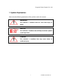
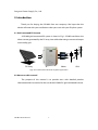
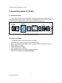
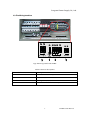
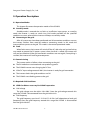
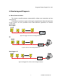
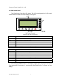
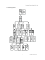
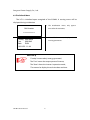
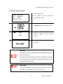
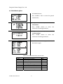
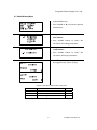
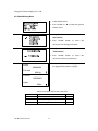
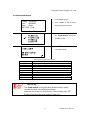
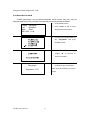
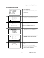
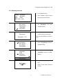
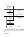
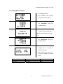
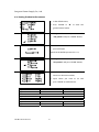
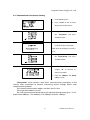
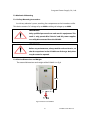
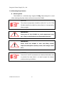
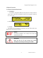
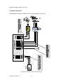
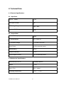
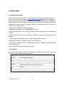
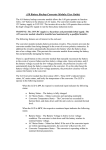
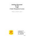
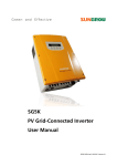
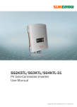
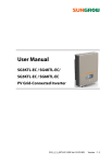
SG10K3 PV Grid-Connected Inverter User Manual SG10K3-UEN-Ver31-201106 Version: 3.1 Table of contents 1. Symbols Explanation .....................................................................................................1 2. Introduction ....................................................................................................................2 2.1 Grid-connected PV inverter ..............................................................................2 2.2 How to use this manual .....................................................................................2 3. Safety Instructions .........................................................................................................3 4. General Descriptions of SG10K3 .................................................................................4 4.1 Circuit Description..............................................................................................4 4.2 Features of SG10K3.............................................................................................4 4.3 The Wiring Interface ...........................................................................................5 5. Operation Description ..................................................................................................6 5.1 Operation Modes ................................................................................................6 5.2 Commissioning ....................................................................................................6 5.3 Required Grid Conditions..................................................................................6 6. Monitoring and Diagnosis ...........................................................................................7 6.1 Basic Communications.......................................................................................7 6.2 LCD Control Panel ...............................................................................................8 6.3 Total Display Menu .............................................................................................9 6.4 The Default Menu............................................................................................. 10 6.5 Start or Stop the Inverter ............................................................................... 11 6.6 Check Running Data ........................................................................................ 12 6.7 Check History Data .......................................................................................... 13 6.8 Check History Data .......................................................................................... 14 6.9 Check Fault Record .......................................................................................... 15 6.10 Enter the Password........................................................................................ 16 6.11 Change Display Language ........................................................................... 17 6.12 Change Date and Time ................................................................................. 18 6.13 Checking Firmware........................................................................................ 19 6.14 Total Power Adjustment ............................................................................... 20 6.15 Setting Run Parameters................................................................................ 21 6.16 Setting Production Parameters .................................................................. 22 6.17 Communication Parameters Setting ......................................................... 23 7. Installation.................................................................................................................... 24 7.1 Checking for Shipping Damage.................................................................... 24 7.2 Basic Installation Requirements ................................................................... 24 7.3 Mechanical Mounting ..................................................................................... 25 7.3.1 Safety Mounting Instructions.............................................................. 25 7.3.2 Device Dimensions and Weight .......................................................... 25 7.3.3 Mounting Requirements....................................................................... 26 7.4 Electrical Connection ...................................................................................... 27 7.4.1 Electrical Connection Requirements ................................................. 27 7.4.2 Wires connection.................................................................................... 28 7.5 Communication Installation .......................................................................... 30 2 7.6 Start and close .................................................................................................. 31 7.6.1 Start the Inverter.................................................................................... 31 7.6.2 Close the Inverter................................................................................... 31 8. Technical Data.............................................................................................................. 32 8.1 Electrical Specifications.................................................................................. 32 8.2 Mechanical Specifications ............................................................................. 32 8.3 Features.............................................................................................................. 33 9. Appendixes................................................................................................................... 34 9.1 Exclusion of Liability ....................................................................................... 34 9.2 Contact Us ......................................................................................................... 34 Sungrow Power Supply Co., Ltd. 1. Symbols Explanation Please note the following explanation of the symbols used in this manual. WARNING! This indicates a condition that can cause fatal injury or death. NOTICE! This indicates a condition that will help to achieve optimal system operation. Caution! This indicates a condition that may cause minor or moderate injury. 1 SG10K3 User Manual Sungrow Power Supply Co., Ltd. 2. Introduction Thank you for buying the SG10K3 from our company. We hope that the device will meet with your satisfaction when you use it with your PV plant system. 2.1 Grid-connected PV inverter A SG10K3 grid-connected PV system is shown in Fig.1. SG10K3 transforms the direct current generated by the PV array into stable alternating current and output to the utility grid. PV Array SG 10 K3 Meter Grid Fig.1 Grid-connected Inverter for PV power application 2.2 How to use this manual The purpose of this manual is to provide users with detailed product information and instructions for the use of the SG10K3 PV grid-connected inverter. SG10K3 User Manual 2 Sungrow Power Supply Co., Ltd. 3. Safety Instructions Please read the instructions in this manual carefully before installing and operating the SG10K3. y Always disconnect the inverter from the grid first. y ALL CONNECTIONS SHOULD ONLY BE UNDERTAKEN BY QUALIFIED PERSONNEL. y All electrical installations shall be done in accordance with local and national electrical codes. y Please contact your authorized system installer if any maintenance is required. y Connection of the SG10K3 to the utility grid must be done only after receiving prior approval from the utility company and performed by qualified personnel. y Completely disconnect the output from the PV array before connecting to the SG10K3 or use other methods to prevent electrical shock hazards. This is important because if the PV array keeps connecting during the connection process may produce dangerous voltages. WARNING! Make sure that the DC input voltage never exceeds 450V. Higher input voltages will damage the SG10K3 and will lead to the loss of any and all warranty rights. 3 SG10K3 User Manual Sungrow Power Supply Co., Ltd. 4. General Descriptions of SG10K3 4.1 Circuit Description Fig.2 shows the main circuit of SG10K3 -a transformer grid-connected inverter. An IGBT full-bridge converts the DC power to AC voltage and current. The AC power is then fed to the grid after being processed by a filter and a transformer. Fig.2 Circuit diagram of SG10K3 4.2 Features of SG10K3 The following are the technical features of SG10K3: 1. 2. 3. 4. 5. 6. 7. The latest power module improves the system efficiency. MPPT auto-optimizing technique makes the most of the PV generation capacity. Multilingual LCD display. Simple parameters settings. Multi communication interface. High reliability due to complete protection functions. Wide DC input voltage range (up to 450V DC). SG10K3 User Manual 4 Sungrow Power Supply Co., Ltd. 4.3 The Wiring Interface Fig.3 The wiring interface of SG10K3 Table4-1 Terminal descriptions Terminal of inverter Description DC INPUT Connected to the PV array GND Earth connection AC OUTPUT To the gird L1,L2,L3,and N RS485 RS485 A/B serial communication port 5 SG10K3 User Manual Sungrow Power Supply Co., Ltd. 5. Operation Description 5.1 Operation Modes This chapter illustrates the operation modes of the SG10K3. Stand-by mode: Standby-mode is entered due to fault or insufficient input power, at stand-by mode the inverter is ready to switch into Grid mode provided all the specified conditions are met, otherwise the inverter will keeps at stand-by mode. Connecting to the grid: After all system tests have been performed and all connection conditions are met, the inverter switches from stand-by mode to connecting mode. In this mode the inverter delivers power to the grid. This mode is the normal operational mode. Fault When faults occur, the inverter will switch off the AC side relay and go into fault or stop mode to protect the PV power system, when the fault is solved, the inverter will wait and test whether all the grid connection conditions are met again, if everything is satisfied, the inverter will start to generate power. 5.2 Commissioning z The inverter works as follows when connecting to the grid: The PV modules are activated and start producing power. z The SG10K3 inverter starts charging the DC bus. z If the DC input voltage exceeds 240 V, the inverter is ready for grid connection. z The inverter checks that grid conditions are OK. z The SG10K3 starts feeding power to the grid. 5.3 Required Grid Conditions GRID Conditions necessary for SG10K3 operation: z Grid voltage The grid voltage must be within 310~450V. Once the grid voltage exceeds this range the SG10K3 is disconnected from the grid within 0.2s. z Grid frequency The grid frequency must be 47~51.5Hz/57~61.5Hz (self adaptation to local grid frequency).Once the grid frequency exceeds this range the SG10K3 is disconnected from the grid with 0.2s. SG10K3 User Manual 6 Sungrow Power Supply Co., Ltd. 6. Monitoring and Diagnosis 6.1 Basic Communications The inverter normally operates automatically, without user interaction and any maintenance. To enable our customers to gain a thorough comprehension about the operation of the inverter, we have provided various data-collection approaches to monitor system data. Data logger Fig.4 Data logger collects data through RS485 bus PC Fig.5 PC collects data through RS485 bus Data logger+ PC Fig.6 Data logger & PC collects data through RS485 bus 7 SG10K3 User Manual Sungrow Power Supply Co., Ltd. 6.2 LCD Control Panel The SG10K3 has a four line LCD display. The LCD control panel has 5 LEDs and 6 buttons below to check or set parameters, see Figure 7. Fig.7 the LCD panel Table 6-1 LED color and meaning LED Color/Meaning POWER Green/The control circuit power supply working state RUN Green/Inverter is in operation mode FAULT Red/A fault occurs in the inverter COM Green/Communication state between inverter and PC GRID Green/The grid parameters(voltage/frequency ) are OK Table 6-2 Function of keys Key Function ESC Return/finish function /Answer questions with a “no” ź Select menu/Reduce/increase value Ź Move left or right to set value ENTER Select menu item/Confirm changes/Answer questions with a “YES” SILENCE Stop the beeper when it makes a sound after a fault occurs . RESET Resets the LCD display Activation of the Background Illumination The background illumination is activated by slightly press any key on the panel. The background illumination is automatically deactivated after 2 minutes to save energy. SG10K3 User Manual 8 Sungrow Power Supply Co., Ltd. 6.3 Total Display Menu Fig.8 The total LCD menu 9 SG10K3 User Manual Sungrow Power Supply Co., Ltd. 6.4 The Default Menu The LCD is initialized upon energized of the SG10K3. A starting menu will be displayed during initialization. 1. The initialization menu, only appear Grid Inverter once after the activation; >>>>>>>>>>> 2. The E-today 000.0kWh P-ac 000.0kW State RUN 06/11/22 11:44 default menu, displays running parameters. NOTICEʽ “E-today” means today’s energy generated; The “P-ac” means the output power of inverter; The “State” shows the inverter’s operation mode; The menu also display the real-time date and time. SG10K3 User Manual 10 basic Sungrow Power Supply Co., Ltd. 6.5 Start or Stop the Inverter 1. In the default menu; E-today 000.0kWh P-ac 000.0kW State RUN 06/11/22 11:44 2. Press “ENTER” or “Ź” to enter the general control menu; 3. Navigate the arrow-pointer to the “Start/Stop” and press “ENTER” button; 4. Navigate the arrow-pointer to the Start “Start” or “Stop” and press “ENTER” Stop button; 5. Press “ENTER” button to confirm the command. NOTICE! Normally the inverter will auto start when conditions are met or faults are removed. The start command of the control menu is provided in case the inverter needs a restart after being stopped by performing stop command in the LCD menu. NOTICEʽ The stop command will let the inverter disconnect the AC contactor and need menu start in the LCD menu. 11 SG10K3 User Manual Sungrow Power Supply Co., Ltd. 6.6 Check Running Data 1. In the default menu; 2. Press “ENTER” or “Ź” to enter the general control menu; 3. Navigate the arrow-pointer to the “Run-inform”; 4. Press “ENTER” button to access the sub-menus of running parameters; 5. Navigate the arrow-pointer to the “Current-inform”; 6. Press “ENTER” button to access the sub-menus of running parameters; 7. Use “ź” to move to next page to check the all the data in 2 pages; Table 6-3 the explanation of the real-time data Data name E-today V-grid I-grid F-grid V-dc I-dc P-ac Temp h-today SG10K3 User Manual Explanation Energy generated today Grid voltage Output AC current Grid frequency DC Voltage (of PV array) DC Current (of PV array) Output ac power Temperature within the enclosure Operation time of today 12 Unit kWh V A Hz V A W ć min Sungrow Power Supply Co., Ltd. 6.7 Check History Data 1. In the default menu; 2. Press “ENTER” or “Ź” to enter the general control menu; 3. Navigate the arrow-pointer to the “Run-inform”; 4. Press “ENTER” button to access the sub-menus of running parameters; 5. Navigate the arrow-pointer to the “Total-inform”; 6. Press “ENTER” button to access the sub-menus of history parameters; 7. Use “ͩ” to move to next page to check the logged history data in 2 pages. Table 6-4 the explanation of the history data Data name E-total h-today h-total CO2-total Explanation The total generated power The Operation time of today Total hours of Operation time Total CO2 weight reduced 13 Unit kWh min h Kg SG10K3 User Manual Sungrow Power Supply Co., Ltd. 6.8 Check History Data 1. In the default menu; 2. Press “ENTER” or “Ź” to enter the general control menu; 3. Navigate the arrow-pointer to the “Run-inform”; 4. Press “ENTER” button to access the sub-menus of running parameters; 5. Navigate the arrow-pointer to the “Total-inform”; 6. Press “ENTER” button to access the sub-menus of history parameters; 7. Use “ź” to move to next page to check E-total the logged history data in 2 pages. 0000KWH CO2-total 000 Kg E-month 0000KWH h-total 000 h Table 6-4 the explanation of the history data Data name E-total h-today h-total CO2-total SG10K3 User Manual explanation The total generated power The Operation time of today Total hours of Operation time Total CO2 weight reduced 14 Unit KWH Min H Kg Sungrow Power Supply Co., Ltd. 6.9 Check Fault Record 1. In the default menu E-today 000.0kWh P-ac 000.0kW State RUN 06/11/22 11:44 2. Press “ENTER” or “Ź” to enter the general control menu 3. Navigate the arrow-pointer to the “Fault-record” and press “ENTER” button. 4. Press “ͩ” button to move to next fault records. Fault type Vdc-high Vac-high Vac-low F-fault Island Dsp-flt PM-flt Temp-flt Com-flt Table 6-5 the explanation of faults Explanations DC voltage is too high Grid voltage is too high Grid voltage is too low Grid frequency is abnormal Island(grid in unavailable) The control DSP malfunctions The IPM power module malfunctions Temperature inside the enclosure is too high Communication fault between LCD and DSP NOTICEʽ The “Fault-record” can log the latest 20 fault records, which includes the fault name and occurred time. Note that one screen can only display 1 fault records, press “ͩ” button to move to next fault records if necessary. 15 SG10K3 User Manual Sungrow Power Supply Co., Ltd. 6.10 Enter the Password SG10K3 parameters are password protected, which means they can only be adjusted upon entry of a password. To enter the password, proceed as follows: 1. In the default menu; E-today 000.0kWh P-ac 000.0kW State RUN 06/11/22 11:44 2. Press “ENTER” or “Ź” to enter the general control menu; 3. Navigate the arrow-pointer to the “Set-param” and press “ENTER” button; 4. Use “Ź“to choose digits, employ “ź” to increase or decrease number; 5. Press Set-param button to confirm the password input. Note that the default password is Password 1111 SG10K3 User Manual “ENTER” 1111. 16 Sungrow Power Supply Co., Ltd. 6.11 Change Display Language 1. In the default menu; E-today 000.0kWh P-ac 000.0kW State RUN 06/11/22 11:44 2. Press “ENTER” or “ ” to enter the general control menu; 3. Navigate the arrow-pointer to the Run-inform Fault-record Start/Stop Set-param “Set-param” and press “ENTER” button; 4. Press “ENTER” button to confirm the Set-param password input; Note that the default password is 1111; Password 1111 5. Navigate the arrow-pointer to the Sys-param Run-param Pro-param Com-param “Sys-param” and press “ENTER” button; 6. Move Language Time Firmware Power-add the arrow-pointer to the “Language” and press “ENTER” button; Load-default 7. Use“ͩ” to change number between 0 Language[1] 0˖CH and 1. 1˖EN 0 represents Chinese and 1 for English; 8. Choose the number you want and press “Enter” to confirm your choice; 17 SG10K3 User Manual Sungrow Power Supply Co., Ltd. 6.12 Change Date and Time 1. In the default menu; E-today 000.0kWh P-ac 000.0kW State RUN 06/11/22 11:44 2. Press “ENTER” or “Ź” to enter the general control menu; 3. Navigate the arrow-pointer to Run-inform Fault-record Start/Stop Set-param the “Set-param” and press “ENTER” button; 4. Press Set-param “ENTER” button to confirm the password input; Note that the default password is Password 1111 1111; 5. Navigate the arrow-pointer to Sys-param Run-param Pro-param Com-param the “Sys-param” and press “ENTER” button; 6. Move the arrow-pointer to the Language Time Firmware Power-add “Time” and press “ENTER” button; Load-default 7. Use “Ź“to choose digits, employ “ͩ” to increase or decrease number; 8. Input the time you want according to your local time and press “Enter” to confirm it; SG10K3 User Manual 18 Sungrow Power Supply Co., Ltd. 6.13 Checking Firmware 1. In the default menu; E-today 000.0kWh P-ac 000.0kW State RUN 06/11/22 11:44 2. Press “ENTER” or “Ź” to enter the general control menu; 3. Navigate the arrow-pointer to Run-inform Fault-record Start/Stop Set-param the “Set-param” and press “ENTER” button; 4. Press Set-param “ENTER” button to confirm the password input; Note that the default password is Password 1111 1111; 5. 5. Navigate the arrow-pointer Sys-param Run-param Pro-param Com-param to the “Sys-param” and press “ENTER” button; 6. Move the arrow-pointer to the Language Time Firmware Power-add “Firmware” and press “ENTER” button; Load-default 7. The firmware is shown on the LCD. Refer to the actual firmware version. 19 SG10K3 User Manual Sungrow Power Supply Co., Ltd. 6.14 Total Power Adjustment 1. In the default menu; 2. Press “ENTER” or “Ź” to enter the general control menu; 3. Navigate the arrow-pointer to the “Set-param” and press “ENTER” button; 4. Press “ENTER” button to confirm the password input; Note that the default password is 1111; 5. Navigate the arrow-pointer to the “Sys-param” and press “ENTER” button; 6. Move the arrow-pointer to the “Power-add” and press “ENTER” button; 7. Use “Ź“to choose digits, employ “ź” to increase or decrease number. Note that the positive symbol “+” can also be changed to negative symbol “-”. This generated power adjustment screen is useful in case the total-power displayed by LCD (E-total) has difference with reading value from the external power measuring device (like an electrical meter). The adjustable range is from -999-+999 kWh. (Power-adj value)= (Real measured value)-(E-total reading value) SG10K3 User Manual 20 Sungrow Power Supply Co., Ltd. 6.15 Setting Run Parameters 1. In the default menu; 2. Press “ENTER” or “Ź” to enter the general control menu; 3. Navigate the arrow-pointer to the “Set-param” and press “ENTER” button; 4. Press “ENTER” button to confirm the password input; Note that the default password is 1111; 5. Navigate the arrow-pointer to the “Run-param” and press “ENTER” button; 6. Use “Ź“to choose digits, employ “ź” to increase or decrease number; 7. Input values you want to set and press ”ENTER” to confirm them. Parm Name Power limitation Start time Parm Value 0~100% 0~10min 21 Default 100% 5min SG10K3 User Manual Sungrow Power Supply Co., Ltd. 6.16 Setting Production Parameters 1. In the default menu; 2. Press “ENTER” or “Ź” to enter the general control menu; 3. Navigate the arrow-pointer to the “Set-param” and press “ENTER” button; 4. Press “ENTER” button to confirm the password input; Note that the default password is 1111; 5. Navigate the arrow-pointer to the “Pro-param” and press “ENTER” button; 6. Use “Ź“to choose digits, employ “ź” to increase or decrease number; 7. Input values you want to set and press ”ENTER” to confirm them. Parm Name Vgrid-max Vgrid-min 50Hz Grid Fgrid-max Fgrid-min 60Hz Grid Fgrid-max Fgrid-min SG10K3 User Manual Parm Value 410~460V 310~360V Default 450V 310V 50.5~52Hz 47~49.5Hz 51.5Hz 47Hz 60.5~62Hz 57~59.5Hz 61.5Hz 57Hz 22 Sungrow Power Supply Co., Ltd. 6.17 Communication Parameters Setting 1. In the default menu; 2. Press “ENTER” or “Ź” to enter the general control menu; 3. Navigate the arrow-pointer to the “Set-param” and press “ENTER” button; 4. Press “ENTER” button to confirm the password input; Note that the default password is 1111; 5. Navigate the arrow-pointer to the “Com-param” and press “ENTER” button; 6. Use “Ź“to choose digits, employ “ź” to increase or decrease number. 7. Input the address and baud rate you want. “Com-param” menu contains some basic communication parameters of the inverter when connected to external monitoring device through RS485 serial communication protocol. The inverter communication address can be in the first line. The range of the address is 0-247. The serial communication baud rate can be adjusted through entering 0, 1, 2 or 3. 0 represents 9600 bps, 1 for 4800 bps, 2 for 2400 bps and 3 for 1200 bps. 23 SG10K3 User Manual Sungrow Power Supply Co., Ltd. 7. Installation This chapter gives installation instructions for SG10K3. 7.1 Checking for Shipping Damage The SG10K3 inverters are thoroughly checked and tested rigorously before they are shipped. Even though they are delivered in a rugged, heavy cardboard box, the inverters can be damaged in shipping which typically is the shipping company’s fault. So you should check the inverter before installation. Please inspect the inverter thoroughly after it is delivered. If any damage is seen please immediately notify the shipping company. If there is any question about potential shipping damage, contact us. A photo of the damage may be helpful. Do not accept unit if visibly damaged or note visible damage when signing shipping company receipt. Please report the damage immediately to the shipping company. Do not remove the unit from packaging. 7.2 Basic Installation Requirements The IP level of SG10K3 is IP20, so it can only be installed indoors. A list of these requirements is shown below: z It is advised not to install the inverter in living quarters, since the inverter may produce some operating noise (< 40 dB). z Avoid installing the inverter in a location subject to vibrations. z The LED and display should always be legible for users. z The ambient temperature should remain from –25°C to 55°C. z It is important to have air freely circulating around the inverter; therefore keep the area within 30 centimeters of the inverter free from obstacles. z The inverter should be mounted in a well-ventilated area. z Avoid mounting the inverter in a dusty area SG10K3 User Manual 24 Sungrow Power Supply Co., Ltd. 7.3 Mechanical Mounting 7.3.1 Safety Mounting Instructions As with any electrical system, touching live components can be hazardous to life. This device contains DC voltage of up to 450V and the grid voltage up to 450V. WARNING! Only qualified personnel can work on this equipment. This work is only permissible if the AC and DC power supplies are safely disconnected from the SG10K3. WARNING! Before any maintenance, always wait for at least 10 min., so that the capacitors in the SG10K3 can discharge. Only then may the cover be opened. 7.3.2 Device Dimensions and Weight The external dimensions and weight of the SG10K3 is in fig 9. Fig.9 Dimensions of SG10K3 25 SG10K3 User Manual Sungrow Power Supply Co., Ltd. 7.3.3 Mounting Requirements z Mounting Place The SG10K3 has a relatively high weight of 175kg. Please keep this in mind when selecting the place where and how to mount the SG10K3. NOTICE! The ambient temperature should be within-25°C to +55°C.The SG10K3 should be installed in a place where it is not exposed to direct sunlight. WARNING! Some parts of the SG10K3 can reach temperature over 80°C. Keep a suitable distance to flammable materials! WARNING! Never install the SG10K3 in areas that likely contain explosive atmospheres (battery rooms, fuel storage rooms etc.)! NOTICE! Since the AC and DC connections are wired to the breakers and or junction box only, there is no need to open the inverter enclosure during installation. SG10K3 User Manual 26 Sungrow Power Supply Co., Ltd. 7.4 Electrical Connection 7.4.1 Electrical Connection Requirements z Grid 230V AC The SG10K3 is designed for 400V grid (three phase).The voltage should be within 310V to 450V and the frequency should be the frequency should be 47-51.5/57-61.5Hz. z PV array limit z Ground The inverter must be grounded in compliance with local safety codes using appropriately sized protective conductors. Notice! All electrical installations must comply with all local and national electrical codes. WARNING! Make sure that the DC input voltage never exceeds 450V.Higher input voltages will damage the SG10K3. 27 SG10K3 User Manual Sungrow Power Supply Co., Ltd. 7.4.2 Wires connection The complete wiring for a SG10K3 is shown schematically in the Fig.10. Fig. 10 Simplified electrical connection diagram SG10K3 User Manual 28 Sungrow Power Supply Co., Ltd. Caution! The wiring of the inverter’s AC and DC cables must only be done with the DC and AC circuit breakers are in the off state. Please follow the steps below: z Isolate the grid (switch off the circuit breaker), and secure it against accidental reactivation. z Connect the wires of the AC cable as follows(through circuit breaker): Grid L1 wire to the terminal marked “L1”. Grid L2 wire to the terminal marked “L2”. Grid L3 wire to the terminal marked “L3”. Grid Neutral wire to the terminal marked “N”. z Connect the DC terminals PV array DC+ wire to the inverter DC+. PV array DC - wire to the inverter DC -. Connect the ground wire z Connecting the RS485A/B wires only if users have purchase our RS485/232 Converter and monitoring software. z Please make sure that all wires are firmly connected. Caution! Make sure tall the wires are firmly tightened. 29 SG10K3 User Manual 7.5 Communication Installation Fig.11 shows the communication installation of the SG10K3 with the PC by RS485 serial communication port. Fig.11 Communication network Fig.12 RS485/RS232 converter SG10K3 User Manual 30 Sungrow Power Supply Co., Ltd. 7.6 Start and close 7.6.1 Start the Inverter To turn on the inverter, please follow the steps below. 1) Switch on the DC side circuit breaker 2) Switch on the AC side breaker 3) The inverter will to check whether that voltage, impedance and frequency parameters are within operating range. 4) If the parameters check is correct, then the LCD will display the normal working screen. 5) Then the inverter will export to the grid and the green Power LED will continuously light (provided there is enough PV power). 7.6.2 Close the Inverter 1) If users want to shut down the inverter, please refer to stop command in the LCD menu in chapter 6. 2) If users want to shut down the inverter immediately, first switch off the AC side breaker then switch off the DC side breaker, incorrect switch off order may cause danger to the personnel and damage to the inverter. 31 SG10K3 User Manual 8. Technical Data 8.1 Electrical Specifications Input Data Max. PV Power 11kW Max. Input Current 50A MPP Voltage Range 220V~380V Maximum DC Voltage 450V Output Data Nominal AC output power 10kW AC Voltage Range 310 ~ 450 V AC AC Frequency Range 47-51.5Hz/57-61.5Hz Power Factor >0.99 at nominal power Peak Efficiency 94.5 % European Efficiency 93.5 % THD of Output Current < 3 % at nominal power 8.2 Mechanical Specifications Dimensions(W x H x D) 530x900 x500 mm Weight 175 kg Ingress Class IP20˄indoor˅ Operating Temperature ˉ25ć̚ˇ55ć SG10K3 User Manual 32 Sungrow Power Supply Co., Ltd. 8.3 Features Cooling Forced air fan cooling Display LCD Communication RS485/Ethernet(Optional) EMC EN61000-6-2 EN61000-6-4 Safety EN 50178 33 SG10K3 User Manual 9. Appendixes 9.1 Exclusion of Liability The content of these documents is periodically checked and revised, when necessary, please call us or check our website www.sungrowpower.com for the latest information. However discrepancies cannot be excluded. No guarantee is made for the completeness of these documents. Please contact our company or distributors to get the latest version. Guarantee or liability claims for damages of any kind are excluded if they are caused by one or more of the following: .Improper or inappropriate use of the product .Operating the product in an unintended environment .Operating the product when ignoring relevant safety regulations in the deployment location .Ignoring safety warnings and instructions contained in all documents relevant to the product .Operating the product under incorrect safety or protection conditions .Altering the product or supplied software without authority .The product malfunctions due to operating attached or neighboring devices beyond allowed limit values. In case of unforeseen calamity or force majeure. 9.2 Contact Us If you have any questions about this product, our hotline will be happy to assist you. Please note the following contact information. Company: Sungrow Power Supply Co., Ltd. Website: www.sungrowpower.com Contact: Mr. Henry (Director of International Trade) Email: [email protected], [email protected] Address: No.2 Tianhu Rd. New & Hight Technology Development Zone, Hefei, Anhui, P.R.China. Zip: 230088 Telephone: +86 551 532 7834, +86 551 532 7845 Fax: +86 551 532 7856 SG10K3 User Manual 34 Industrial