1
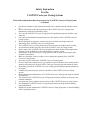
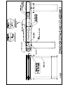
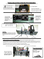
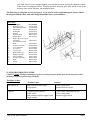
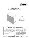
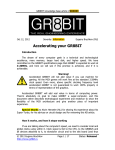
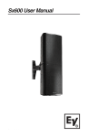
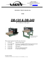
1032 N. Irving St.
Allentown, Pa. 18109 USA
Phone# 610 434-6004 Fax# 610 434-6607
Web Site www.vastex.com
E-Mail [email protected]
INSTRUCTION MANUAL
FOR
DB-120 & DB-240
W/ X-Series Conveyor
DB-240 SHOWN WITH
OPTIONAL LEGS.
This manual contains the following documents:
1.
01-00-027
(Safety Instructions)
2.
01-16-003-007 (Conveyor Assembly & Belt Tracking Instructions)
3.
01-01-008
(Operation and Maintenance Instructions)
4.
01-00-005
(Warranty)
5.
01-00-006
(Warranty Implementation)
6.
01-00-015
(Terms and Conditions)
Revised 10/28/05
F:\Shared\Vastex\01-Manuals & Doc\01-DB120\01-01-007 DB-XSERIES_Cover.wpd
Safety Instruction
For the
VASTEX Conveyor Curing System
These Safety Instructions must be present at the VASTEX Conveyor Curing System
at all times
First always read these safety instructions and the user’s manual carefully and follow these
up.
In case of questions on the safe functioning of the VASTEX conveyer Curing System
immediately contact the responsible persons.
Never use the VASTEX Conveyor Curing System for application purposes, which it is not
meant for.
It is restricted for unauthorized personnel to be in the nearness of the VASTEX Conveyor
Curing System.
Before starting the activities the operator must possess all the knowledge on the safe
functioning of the VASTEX Conveyor Curing System.
The VASTEX Conveyor Curing System may never be turned on without correct fencing.
An experienced operator may only operate the VASTEX Conveyor Curing System.
Before usage of the VASTEX Conveyor Curing System check whether all the applications
function, in case of doubt never take risks and always contact a expert.
Switching the VASTEX Conveyor Curing System on and off, must always happen with
complete consciousness
Make sure, that there is always proper overview during the operating of the VASTEX
Conveyor Curing System.
Never put excessive load on the VASTEX Conveyor Curing System.
In case a abnormal symptoms occurs, for example excessive vibration, noise, strong smell or
smoke development, turn off the VASTEX Conveyor Curing System and contact an expert.
Immediately turn off the VASTEX Conveyor Curing System if products become jammed in
the system
A authorized person may only open the switch-box of the VASTEX Conveyor Curing
System.
During cleansing and maintenance, the VASTEX Conveyor Curing System must be switched
off completely.
The operator of the VASTEX Conveyor Curing System must be informed on the proper way
to handle calamities.
An expert must always conduct repair activities on the VASTEX Conveyor Curing System.
For cleaning the VASTEX Conveyor Curing System always use the prescribed cleaning
liquid and material.
Rapport any unsafe condition the VASTEX Conveyor Curing System has, or unsafe handling
to the responsible persons.
UNPACKING AND ASSEMBLY INSTRUCTIONS:
DOC# 01-16-003
Please See the Photo Page 01-16-006 for Visual Aid.
1)
Please inspect for any hidden shipping damages and notify the trucking
company to submit a hidden damage report if necessary.
2)
Assemble the conveyor, see 01-16-006 for instructions.
3)
Install the legs if you have a floor model.
4)
Tighten all the bolts and turn the conveyor over (right side up).
5)
Install the chain guard!
• Do not operate the conveyor without the guard in place !
Belt installation:
6)
Install belt around the pulleys and over the alignor as shown in the diagram
on sheet 01-16-004.
7)
You are ready to plug in the conveyor power and start tracking the belt. See
the diagram 01-16-005 on belt tracking.
8)
Place the heat chamber onto the slider bed with the control to the right side,
same as the conveyor control, and plug it into a new and properly rated
outlet. See operation instructions for outlet requirements.
9)
See operation instructions 01-01-008 for electrical requirements, operation
recommendations and maintenance.
F:\Shared\Vastex\01-Manuals & Doc\16 X-SERIES CONVEYOR\01-16-003.wpd
Conveyor Assembly Photo’s and Assembly Procedure.
Front
section
Conveyor
extension
(not all models)
Belt
Doc# 01-06-006
Remove conveyor parts from
skid and lay out on large table
or floor upside down as shown.
Drive
section
3/8-16 x 3/4 long bolts with lockwashers and nuts are provided to connect the front section to the drive section. If your conveyor is longer
then 48” there will be extensions which bolt together as shown.
Please install all bolts before tightening. A 9/16 wrench will be needed
to tighten the bolts and nuts. The lockwasher goes next to the nut.
If you have legs with your conveyor, bolt on as shown.
3/8-16 x3/4 bolts with lock washer, washer and nuts
are provided. The lock washer goes next to the nut.
Install the chain guard before plugging in your conveyor. The chain guard will protect you from getting
an injury from the chain & sprocket.
Alligator lace
Alignor
After tightening all the bolts carefully turn the conveyor onto its feet or your table. The belt
needs to be installed as shown in DOC# 01-16-004 making sure you thread it over the alignor.
Install the pin into the alligator lace and make sure the two ends of the belt are centered to each
other. If one person positions the belt ends and holds the belt into position a second person can
install the pin. Be sure when pushing on the pin you grip it close to the belt if the pin bends it
will be difficult to remove the kink in the pin. Plug the conveyor into a properly grounded 120
volt outlet and turn the controller on. The numbers on the dial are for reference only. Time the
belt with a watch and set the speed to the desired seconds in the heat.
X-Series conveyor motor, chain and control maintenance.
In order to adjust the chain tension or remove the control assembly, the chain guard must first be removed.
DO NOT RUN YOUR
CONVEYOR WITHOUT THE CHAIN
GUARD IN PLACE.
Chain Guard
To remove the chain guard:
Unfasten the two black sheet metal
screws at the top. Be sure to replace
the guard after adjustment is made.
View with chain guard removed.
Control assembly
mounting screw
(3 of 3). There is a
washer/spacer
under the panel at
each bolt.
Control assembly
mounting screws
(2 of 3). There is a
washer/spacer
under the panel at
each bolt.
X-Series conveyor control assembly.
Belt speed control
Gear Motor
Model# XCB-DB-XXX
(XXX = 120 or 240 volt)
Caution:
With the control assembly removed there
are open wires and electrical connections.
Severe shock can occur if caution is not
taken.
Fuse holder
Power cord
Belt speed control knob
Motor sprocket
Setting the low speed pot adjustment: (small screw driver with plastic handle is needed)
Turn the speed pots clockwise to increase the speed and counterclockwise to decrease. The low speed pot should be set so the belt
(or sprocket) moves very slow at the lowest setting on the controller, just before the controller is clicked in the off position. The
high setting is set so 90 VDC is the maximum voltage to the motor, a volt meter is needed for the high speed adjustment. The control assembly should be placed on a bench so the speed pots are up and accessible.
Caution: Do not to touch the open wires around the controller and the fuse holder.
Pot near the white wires LOW SPEED.
Pot near the blue wires HIGH SPEED.
Vastex International Inc.
X-Series conveyor control
instructions.
This view of the control
assembly “upside down” is
to show you the speed pot
adjustments on the bottom
side of the controller.
Doc# 01-16-007
www.vastex.com
OPERATION AND MAINTENANCE MANUAL
FOR VASTEX DB120 and DB240 with X-Series Conveyors
CONTENTS:
PAGE
SECTION
1.0 INTRODUCTION . . . . . . . . . . . . . . . . . . . . . . . . . . . . . . . . . . . . . . . . . . . . . . . . . . . . . . . . . . . . . . . . . . . . . . . . . . . .
2.0 PACKAGE CONTENTS . . . . . . . . . . . . . . . . . . . . . . . . . . . . . . . . . . . . . . . . . . . . . . . . . . . . . . . . . . . . . . . . . . . . . . .
3.0 HEAT CHAMBER ASSEMBLY . . . . . . . . . . . . . . . . . . . . . . . . . . . . . . . . . . . . . . . . . . . . . . . . . . . . . . . . . . . . . . . .
4.0 CONVEYOR ASSEMBLY INSTRUCTIONS . . . . . . . . . . . . . . . . . . . . . . . . . . . . . . . . . . . . . . . . . . . . . . . . . . . . .
5.0 POWER REQUIREMENTS . . . . . . . . . . . . . . . . . . . . . . . . . . . . . . . . . . . . . . . . . . . . . . . . . . . . . . . . . . . . . . . . . . . .
5.1
DB-120 . . . . . . . . . . . . . . . . . . . . . . . . . . . . . . . . . . . . . . . . . . . . . . . . . . . . . . . . . . . . . . . . . . . . . . . . . . . .
5.2
DB120-200 . . . . . . . . . . . . . . . . . . . . . . . . . . . . . . . . . . . . . . . . . . . . . . . . . . . . . . . . . . . . . . . . . . . . . . . . .
5.3
DB240 . . . . . . . . . . . . . . . . . . . . . . . . . . . . . . . . . . . . . . . . . . . . . . . . . . . . . . . . . . . . . . . . . . . . . . . . . . . .
5.4
DB-120-EU . . . . . . . . . . . . . . . . . . . . . . . . . . . . . . . . . . . . . . . . . . . . . . . . . . . . . . . . . . . . . . . . . . . . . . . .
5.0 OPERATING INSTRUCTIONS . . . . . . . . . . . . . . . . . . . . . . . . . . . . . . . . . . . . . . . . . . . . . . . . . . . . . . . . . . . . . . . .
6.0 PROPER CURE . . . . . . . . . . . . . . . . . . . . . . . . . . . . . . . . . . . . . . . . . . . . . . . . . . . . . . . . . . . . . . . . . . . . . . . . . . . . . .
6.1
CURING PLASTISOL WITH INFRARED: . . . . . . . . . . . . . . . . . . . . . . . . . . . . . . . . . . . . . . . . . . . .
7.0 CONTROLS AND SYSTEMS DESCRIPTION . . . . . . . . . . . . . . . . . . . . . . . . . . . . . . . . . . . . . . . . . . . . . . . . . . . .
7.1
TOGGLE SWITCH . . . . . . . . . . . . . . . . . . . . . . . . . . . . . . . . . . . . . . . . . . . . . . . . . . . . . . . . . . . . . . . . .
7.2
OPTIONAL CONTROL DIAL . . . . . . . . . . . . . . . . . . . . . . . . . . . . . . . . . . . . . . . . . . . . . . . . . . . . . . .
7.3
BELT SPEED CONTROL . . . . . . . . . . . . . . . . . . . . . . . . . . . . . . . . . . . . . . . . . . . . . . . . . . . . . . . . . . .
7.4
HEATER HEIGHT ADJUSTMENT . . . . . . . . . . . . . . . . . . . . . . . . . . . . . . . . . . . . . . . . . . . . . . . . . . .
7.5
GEAR MOTOR . . . . . . . . . . . . . . . . . . . . . . . . . . . . . . . . . . . . . . . . . . . . . . . . . . . . . . . . . . . . . . . . . . . .
9.0 CONVEYOR
9.1 BELT . . . . . . . . . . . . . . . . . . . . . . . . . . . . . . . . . . . . . . . . . . . . . . . . . . . . . . . . . . . . . . . . . . . . . . . . . . . . . . .
9.2 ALIGNOR . . . . . . . . . . . . . . . . . . . . . . . . . . . . . . . . . . . . . . . . . . . . . . . . . . . . . . . . . . . . . . . . . . . . . . . . . . .
9.3 PULLEYS . . . . . . . . . . . . . . . . . . . . . . . . . . . . . . . . . . . . . . . . . . . . . . . . . . . . . . . . . . . . . . . . . . . . . . . . . . .
10.0 MAINTENANCE
10.1 ELECTRICAL CONNECTIONS . . . . . . . . . . . . . . . . . . . . . . . . . . . . . . . . . . . . . . . . . . . . . . . . . . . . . . . .
10.2 LINT BUILDUP . . . . . . . . . . . . . . . . . . . . . . . . . . . . . . . . . . . . . . . . . . . . . . . . . . . . . . . . . . . . . . . . . . . . . .
10.3 MOTOR & ELEVATOR CHAIN . . . . . . . . . . . . . . . . . . . . . . . . . . . . . . . . . . . . . . . . . . . . . . . . . . . . . . .
10.4 SPARE PARTS WITH GEAR MOTOR EXPLODED VIEW . . . . . . . . . . . . . . . . . . . . . . . . . . . . . . . .
11.0 TROUBLESHOOTING GUIDE . . . . . . . . . . . . . . . . . . . . . . . . . . . . . . . . . . . . . . . . . . . . . . . . . . . . . . . . . . . . . . .
1
1
2
2
2
2
2
2
2
2
2
2
3
3
3
3
3
3
3
4
4
4
4
4
4
5
1.0 INTRODUCTION:
Congratulations, you have chosen a VASTEX conveyor curing system. VASTEX has been
designing and building dryers since 1965 and has the knowledge and expertise to supply a quality dryer
and help you keep it running for many years to come. VASTEX has innovated many of the features
found in conveyor ovens today from control methods and modular features to air movements and belt
tracking.
We hope the unpacking and assembly went smoothly and welcome any comments or
suggestions to help make the process easier. Please read this document thoroughly as it will help you
with the learning process on your new dryer.
2.0 PACKAGE CONTENTS
In your package, you should have found:
1) Heat chamber
1) Conveyor bed front end (with belt alignor)
1) Conveyor bed rear end (with motor and control)
1) Conveyor belt (be careful not to cut)
1) Manilla envelope with this manual and hardware
1) Set of legs (optional on DB-120 & DB-240)
1) Conveyor extension (optional adds 18" of length to standard 48" conveyor)
Vastex DB-120/240 Operating instructions, DOC#01-01-008
Page 1
3.0 HEAT CHAMBER ASSEMBLY
Assembly of the heat chamber was done at Vastex. It was run and tested for one hour minimum. The
heat chamber will be placed on the conveyor and should not be positioned over the motor and control.
You are now ready to plug into the properly grounded outlet. See the section 5.0 for power
requirements.
4.0 CONVEYOR ASSEMBLY INSTRUCTIONS.
See Document #01-16-003, 004, 005, 006 included with manual.
5.0 POWER REQUIREMENTS
Outlets must be grounded and tight.
5.1 DB120
The DB120 is designed to operate at 120volt AC on a dedicated circuit and will draw 16.5 amps.
You must consult an electrician to prepare the outlet and size the wire for the application. A 12
gauge wire is the minimum size that should be used for a 16.5 amp load.
Note: The plug is a 20 amp Nema 5-20p, requiring the 5-20R receptacle.
5.2 DB120-200
The DB120-200 is designed to operate at 200volt AC on a dedicated circuit and will draw 12
amps. You must consult an electrician to prepare the electrical hookup and size the wire for the
application. A 14 gauge wire is the minimum size that should be used for the 12 amp load.
Note: A 14 gauge cord is supplied. Customers electrician must install outlet.
5.3 DB240
The DB240 is designed to operate at 240volt AC on a dedicated circuit and will draw 13.5 amps.
You must consult an electrician to prepare the outlet and size the wire for the application. A 14
gauge wire is the minimum size that should be used for a 13.5 amp load
Note: The plug is a 15 amp Nema 6-15p, requiring the 6-15R receptacle.
5.4 DB-120-X-EU
The DB-120-X-EU is designed as a 240 volt machine with the Continental Europe plugs.
The 2000 watt heat chamber will draw 8.5 amps and the conveyor well under 1 amp. Please
consult your local electrocution for proper outlet installation.
Note: The plug is a 16 amp CEE 7/7, requiring the proper receptacle.
5.0 OPERATING INSTRUCTIONS
A.
Be sure your breaker is in the off position and the dryer switch or dial is turned off. Then plug
the unit into the properly rated outlet. See section 5.0 for power requirements.
B.
Turn the belt control on and adjust the speed for 25 seconds travel through the tunnel. An object
Vastex DB-120/240 Operating instructions, DOC#01-01-008
Page 2
C.
D.
E.
F.
placed on the belt then timed through the tunnel is the best way to set this time.
Turn the heat switch “ON”, or the optional temperature dial to “High”.
Allow 15-20 minutes for the heater to get to full temperature before using.
Adjust the heater height to approximately 3" above the product.
If needed, change the belt speed or change the heater height to get the proper cure. (See section
6.0 for help with the proper cure.) If you have the optional temperature dial you can also lower
the heat setting depending on the substrate.
6.0 PROPER CURE
6.1 CURING PLASTISOL WITH INFRARED:
Plastisol ink can fully cure in approximately 15-25 seconds. The ink itself throughout must
achieve 310-320 degrees to cure and fuse to the garment. Actual cure times can vary depending
on environmental conditions such as garment color, ink color, thickness and manufacturer.
Aggressive air movements, though desirable, are not necessary with plastisol. Proper exhaust is
important for expelling effluents from the curing chamber and ultimately from the work
environment. Use a temperature gun to measure the skin temp.
7.0 CONTROLS
7.1 TOGGLE SWITCH (standard)
DB-120: 20 amp single pole breaker switch.
DB-240, DB-120-200 and EU: 20 amp double pole breaker switch.
This breaker/switch turns the power on and off to the heater. It will trip if an electrical short is
detected. Consult factory if frequent trips occur. (Caution! The plug must be removed before
entering control box or any servicing to the heater head.)
Switch output light.
The red pilot light next to the breaker switch is wired to the output side. When the breaker/switch
is sending power to the heater, the pilot light will illuminate.
(See troubleshooting guide for light diagnostic functions.)
7.2 OPTIONAL CONTROL DIAL
DB-120-HC: 120 volt BiMetal variable control timer
DB-120-200-HC, DB-120-X-EU-HC and DB-240-HC: 240 volt BiMetal variable control timer.
An optional control dial is available for the DB120, DB120-200 and DB240 dryers. This dial
allows the user to adjust the heat from low to high (full power).
The control has positions low-2-3-4-5 and High. The controller turns the power to the heater on
and off to vary the temperature. The higher the number on the controller the longer the on cycle
and shorter the off cycle is. The High position keeps the power on constantly.
Control output light.
The green pilot light next to the controller is wired to the output side of the controller. When the
controller is sending power to the heater, the pilot light will illuminate.
(See troubleshooting guide for light diagnostic functions.)
7.3 BELT SPEED CONTROL
The control takes the AC voltage and converts it to DC voltage and varies it from 0 to 90 volts.
The dial is for reference only. Speed can vary from location to location depending on the input
voltage. You should time the belt and note what dial position gives you desired number of
seconds in the chamber.
7.4 HEATER HEIGHT ADJUSTMENT
The crank handle on top of the dryer controls the heater height, which is another way to adjust
the amount of time it takes to cure a garment. The height can be adjusted from 2" to 7" off the
belt. The optimal height is 2.5" off the substrate in most cases, but this can be changed to
whatever setting you desire.
DB120 and DB240 Manual
Page3
7.5 GEAR MOTOR
A 90 Volt DC gear motor is located to the rear of the conveyor. It drives the rear pulley and belt
via a roller #25chain and 25B22 sprockets. A one amp fuse is located on the belt control box to
protect the belt control.
9.0 CONVEYOR
9.1 BELT
The conveyor belt is made of Teflon coated fiberglass. It is joined together with an alligator lace
using a steel pin to connect each side. The belt will not burn under normal conditions but the
dryer should always have the belt moving while the heaters are above 500 degrees. The belt
should remain tracked in the center of each pulley. (See 01-16-004, 005, 006 for installation and
tracking adjustments.)
9.2 ALIGNOR
The alignor is a device for tracking to your belt and keeping it on the pulley. As the belt moves
from side to side the alignor is used for adjustments to keep it centered. The belt does not have to
be perfectly centered on the pully but just not hanging over either edge.
9.3 PULLEYS
The pulleys at either end of the conveyor are made by VASTEX of 41/2" inch tubing with 3/4
inch center shaft. They are mounted on self aligning flange bearing blocks for precision rolling.
A belt lagging material is used on each pulley for better belt grip and aid in the tracking.
10.0 MAINTENANCE
Your VASTEX dryer has few points that need maintaining. The most important first step is to follow
the unpacking and setup instructions. The proper electrical hookup and exhaust duct installation will
insure the most can be achieved from your investment. Turn off power at your disconnect before
entering any part of the machine.
10.1 ELECTRICAL CONNECTIONS
Electrical connections will loosen in time from heating and cooling. Every three (3) months the
power should be turned off at the external disconnect and all the points of connection should be
inspected and tightened.
10.2 LINT BUILDUP
As with your clothes dryer at home lint will build up where ever air is flowing over garments.
10.2.1 The optional exhaust blower, located on the rear of the machine, and any air paths
leading to the blower should be cleaned every 2-3 months depending on usage. To
perform the cleaning, remove the two black covers on top of the chamber and the blower
box cover, (left side of machine). Remove the lint build up and any other foreign matter
around the air slots and the blower “squirrel” cage.
10.2.2 Every six months the top cover should be removed to clean around the heater and any
other visible debris buildup.
(Note: Restricting the air flow can do damage to electrical components, inhibit your
dryer’s performance and cause a fire.
10.3 MOTOR & ELEVATOR CHAIN
Chain can loosen in time and should be inspected, tightened and lubricated when necessary. The
motor chain is located in the rear of the conveyor. And the elevator chain can be accessed by
removing the lid and baffle on top of your chamber.
(Caution: Do not over tighten chain, damage to bearings may occur.)
10.4 SPARE PARTS
VASTEX stocks parts used on current model machines. Also any older machine can be upgraded
to new style components to keep their controls modern and operating. But having spare parts on
DB120 and DB240 Manual
Page4
your shelf can save you overnight shipping costs and the downtime waiting for shipment of parts
in the event of a component failure. The only downside of buying spare parts ahead of time is the
warranty starts on the ship date, not installation date.
The Following is a diagram of your gear motor. If you need to order replacement parts, please consult
the diagram and the chart, and order using the manufacturer’s part numbers.
Motor Parts
No.
Description
1
High Speed Gear
2
Inter-High Speed Gear
5
Output Gear
6
Bearing Kit
7
Spacers
8
Retaining Ring
9
Output Shaft
10
High or Inter-Low Speed
Gear Shaft
11
Inter-High Speed Gear
Shaft
12
Gearcase Assembly
13
Cover Assembly
14
#6-32 Screw
15
#10-32 Screw
16
Brush Holder Cap
17
Endbell Assembly
18
Stator Assembly
19
Armature Assembly
20
Brush
21
Spring
Part Number
A11336-0003
A07979-0002
H06099-0003
E12489-0001
K09087-0002
R01877-0007
J06171-0023
J06165-0001
J06165-0001
D08012-0010
D11324-0005
R12132-0002
R12022-0008
K09127-0001
D11325-0001
C09073-0007
K09128-0002
K09129-0001
E13418-0001
11.0 TROUBLESHOOTING GUIDE
Caution! Unplug unit before attempting repairs or entering any part of this unit. See the last print in this
manual for a point to point wiring schematic.
Problem: No heat
Condition
Possible Cause
Solution
Pilot light is on.
Bad connection after toggle.
Failed heater.
Check connections
Return heater for repair.
Light off
Customer power failed or
failed outlet.
Bad connection before toggle Failed
toggle switch.
Check outlet with another device.
Check connections.
Replace toggle switch
DB120 and DB240 Manual
Page5
Vastex Warranty
Doc#01-00-005 Revised 11/20/2002
Vastex, hereinafter referred to as “seller” warrants only to its original “purchaser”, who holds a copy
of the original invoice and is the original end user of the equipment in question, its new equipment against
defects in workmanship on a pro-rated basis for a period of three (3) years from the date of shipment to buyer
and receipt of payment in full. Infrared heaters installed by Vastex in a new dryer will be covered for a period
of (10) years. Replacement parts are covered for a period of (1) year from ship date contingent on payment in
full, with the exception of replacement infrared heaters, which have a (3) year warranty. All sales made
through Vastex dealers must be certified by that dealer before a warrantied replacement is issued.
This warranty is expressly contingent upon the buyer delivering to seller, at the address below,
with all transportation charges prepaid, the part or parts claimed to be defective within the above
mentioned period (3) years for new equipment, (10) years on the heaters and (1) year for replacement
parts, with the exception of replacement infrared heaters, which have a (3) year warranty. If the
machine in question is less than a year old, it will be shipped to the customer at no charge, with an
RGA issued by Vastex for the defective part. The defective part must be shipped back to Vastex within
30 days or the account will be billed. If the equipment is more than a year old, the part will be shipped
after we receive the defective part. If it’s necessary to expedite the movement of parts and to minimize
down time to the buyer, the replacement part shall be supplied on a C.O.D. basis. If testing and analysis
of said part by the seller or its supplier discloses that said part is defective, the cost of said part will be
refunded to the buyer on a pro-rated basis.
Except as otherwise provided herein, the equipment is being sold “as-is”. Final determination of the
suitability of the equipment for the use contemplated by the buyer, is the sole responsibility of buyer, and
seller shall have no responsibility in connection with the suitability.
All warranties implied by law, including the implied warranties of merchantability and fitness are
hereby limited to workmanship and defective parts to a period of (3) years for new equipment and 10 years
for the heaters in said equipment and (3) years (for replacement infrared heaters) and (1) year (for
replacement parts) after date of shipment to first buyer. The express warranty and remedies contained herein
and such implied limited warranties are made solely to the sole warranties and remedies and are in lieu of all
other warranties, guarantees, agreements, and other liabilities, whether express or implied, and all other
remedies for breach of warranty or any other liability of seller, in no event shall seller be liable for
consequential damages.
No person, agent, distributer, or service representative is authorized to change, modify or extend the
terms hereof in any manner whatsoever.
These terms and conditions are an essential part of the transaction between the parties and constitute
the entire agreement between them with respect to the same.
Some states do not allow limitation on how long an implied warranty lasts of the exclusion or
limitation of incidental, or consequential damages, so the above limitation may not apply to you.
This warranty gives you specific legal rights, and you may also have other rights which vary from
state to state.
Infrared heaters are the only replacement parts covered for a period of (3) years from date of shipment
and contingent to receipt of payment in full.
Electrical components can not be returned once installed unless proven defective.
Please refer to doc. 01-01-006 for warranty implementation help.
Please refer to doc. 01-00-015 for specific terms and conditions of sale and the limited warranty.
Please refer to doc. 01-00-017 for V-2000HD printer warranty.
This revised warranty effective as of 11/20/2002
F:\Shared\Vastex\01-Manuals & Doc\00-misc\01-00-005 (Warranty).wpd
VASTEX
INTERNATIONAL
1032 N. IRVING ST.
ALLENTOWN PA. 18109 USA
VASTEX WARRANTY IMPLEMENTATION SHEET
Please read this document in order to fully understand the warranty.
Doc.# 01-00-006
Your new Vastex equipment is protected against *manufacturers’ defects by our warranty, completely explained
in doc# 01-00-017 for the V2000-HD series manual printer and in doc# 01-00-005 for all other Vastex
manufactured equipment. Please refer to these documents for the **warranty term and specific concerns about
the warranty. The following are some important facts and requirements for the proper implementation of the
warranty.
1.0 Everything is covered!
2.0 **Warranty Term is defined as:
Ship date from VASTEX to the date the item in question is
returned to VASTEX for inspection and repair.
3.0 *Manufacturers defects are defined as:
Parts determined to be defective in workmanship which will lead
up to a premature failure. The determination will be made only
by the manufacturer of the item in question.
4.0 To take advantage of the warranty the following steps must be taken:
4.1
The equipment must be paid for in full.
4.2
The item in question must be shipped to VASTEX for evaluation with all shipping costs incurred
by the buyer.
4.3
If the item is deemed as a manufacturer’s defect it will be repaired or replaced within 2 business
days from the time received. The shipping cost back to the customer located in the continental
United States will be paid by VASTEX if a warranty item.
4.4
If the item in question must be replaced immediately and is more than a year old, it will
have to be purchased at list price and will be shipped COD. A pro-rated credit will be given
promptly if the returned item is a valid manufacturer’s defect.
4.5
If the equipment was shipped less than a year before the date of the service call and a technician
confirms the part needed for repair, the replacement will be shipped before the replacement is
shipped back. An RGA will be issued and must accompany the old part to VASTEX within 30
days or the account will be billed.
5.0 Important facts about the condition of shipped equipment:
5.1
Dryers are partially assembled with the belts tracked and the machine run at full temperature for a
min. of 1 ½ hours.
5.2
Printers are partially assembled, inspected, and adjusted for all heads down prior to partial
disassembly and packing.
5.3
Exposing units are fully assembled and tested with the maximum screen size for vacuum
integrity, timer operation and light output.
6.0
This document is in addition to the standard warranty and only helps the customer understand how to take
advantage of the warranty. In no way does this document override the standard warranty or the terms and
conditions of sale and the limited warranty doc# 01-00-015.
Please see doc# 01-00-015 for specific terms and conditions of sale and the limited warranty
VASTEX
INTERNATIONAL
F:\Shared\Vastex\01-Manuals & Doc\00-misc\01-00-006 (Warranty Implementation).wpd
1032 N. IRVING ST.
ALLENTOWN PA. 18109 USA
Vastex International, Inc.
TERMS AND CONDITIONS OF SALE AND LIMITED WARRANTY
Doc.#01-00-015
1. Buyer’s order will constitute an offer in accordance with the terms hereof and such offer, upon acknowledgment of Seller, will constitute
the agreement between Buyer and Seller. Buyer’s order after such acknowledgment by Seller will not be subject to cancellation, change or reduction in
amount, or suspension by Buyer of deliveries, unless prior to such action Buyer has obtained Seller’s written consent. Notwithstanding anything to the
contrary in Buyer’s Purchase Order or other communications, the parties agree to be bound by these Terms and Conditions. Acceptance of the product
by the Buyer shall be deemed to constitute unconditional acceptance of these Terms and Conditions.
2. Any of these terms, conditions and provisions of Buyer’s order which are inconsistent with Seller’s acknowledgment and these Terms and
Conditions of Sale shall not be binding on the Seller and shall be considered not applicable to any sale so made. No waiver, alteration or modification of
any of the provisions on either side of the document shall be binding upon Seller unless agreed to in writing by Seller.
3. (a) All prices are F.O.B. Seller’s Plant and method of delivery and routing shall be at Seller’s discretion, unless specifically otherwise
stated herein. Notwithstanding any agreement to pay freight, delivery of products purchased hereunder to a common carrier or licensed trucker shall
constitute delivery to Buyer and be determinative of the date and time of shipment and all risk of loss or damage in transit shall be borne by Buyer. If the
Buyer fails to accept the goods from the common carrier or licensed trucker, the Seller shall be entitled to claim payment from the Buyer. Seller shall
arrange for storage, the risk and the cost, including insurance costs, to be borne by the Buyer (and Buyer agrees to pay such amounts upon demand)
except if the failure to accept delivery is due to any of the exceptions noted in Paragraph 4.
(b) Terms of payment shall be as stated on invoice.
4. It is understood that deliveries will be made in accordance with Seller’s regular production schedule. Every reasonable effort will be made
to meet the Buyer’s required delivery dates but Seller will not be liable for damages or be deemed to be in default by reason of any failure to deliver or
delay in delivery due to any preference, priority, allocation or allotment order issued by the Government, whether Federal, State or local, or causes
beyond its control including but not limited to, Acts of God or a public enemy, acts of Government, fires, floods, epidemics, quarantine restrictions,
strikes, lockouts, freight embargoes, severe weather, unavailability of materials or shipping space, delays of carriers or suppliers or delays of any
subcontractors. Should delay in delivery be caused by any of the circumstances mentioned in this paragraph, such extension of the delivery period shall
be granted as is reasonable under the circumstanced of the case. Should delay be caused by an event not specifically mentioned in this paragraph,
damages will be limited to cancellation of the purchase order without penalty, and refund of any monies deposited or prepaid on the purchase order with
no liability for any consequential or incidental damages.
5. Seller reserves the right to increase the prices prior to Seller’s acceptance of order and/or after expiration of any price quoted by Seller.
6. Unless otherwise stated in writing, Seller’s prices do not include sales, excise, value-added or other taxes. Consequently, in addition to the
price specified herein, the amount of any present or future sales, use, excise, value-added or other tax applicable to the manufacture, sale, purchase or
use of the products hereunder shall be paid by Buyer, or in lieu thereof, Buyer shall provide Seller with a valid tax exemption certificate acceptable to
the taxing authorities.
7. Seller reserves the right, at any time, to revoke any credit extended to Buyer because of Buyer’s failure to pay for any products when due or
for any other reason deemed good and sufficient by Seller and in such event, all subsequent shipments shall be paid for prior to at delivery at Seller’s
option.
8. (a) SELLER’S LIABILITY SHALL BE LIMITED TO SELLER’S STATED SELLING PRICE PER
UNIT OF ANY DEFECTIVE GOODS AND SHALL IN NO EVENT INCLUDE BUYER’S MANUFACTURING COSTS, LOST PROFITS,
GOODWILL, OR ANY OTHER SPECIAL, INDIRECT, INCIDENTAL OR CONSEQUENTIAL DAMAGES, ARISING OUT OF THE
AGREEMENT, THIS CONTRACT, THE SALE OF THE PRODUCTS TO THE BUYER OR THE USE OR THE PERFORMANCE OF THE
PRODUCTS. Seller may at its discretion repair, replace or give the Buyer credit (pro-rated) for such defective products.
(b) Notwithstanding anything herein to the contrary, Seller shall have no liability for alleged defects with the products which are not
specified in written notice from the Buyer to the Seller within thirty-six (36) months from the date of shipment of machines. Seller shall pass to Buyer
any warranty received by Seller from the manufacturer of Limited Life Components, which in most cases is 12 to 18 months.
(c) Seller shall have no liability under this Limited Warranty unless Buyer has paid in full for the products. Further, this Limited Warranty is
expressly contingent on Buyer’s delivery to Seller, all costs prepaid, the defective part(s) within thirty-six (36) months of shipment to Buyer, together
with a written statement specifying the alleged defect(s). Any replacement part(s) shall be shipped to Buyer on a C.O.D. basis.
(d) SELLER SPECIFICALLY EXCLUDES ALL WARRANTIES, EXPRESSED, IMPLIED OR OTHERWISE, EXCEPT AS STATED
EXPLICITLY IN THESE TERMS AND CONDITIONS OF SALE. SELLER DISCLAIMS THE WARRANTY OF MERCHANTABILITY AND
FITNESS FOR A PARTICULAR PURPOSE.
9. The remedies herein reserved by Seller shall be cumulative and in addition to any other legal remedies. No waiver of a breach of any
portion of this contract shall constitute a waiver of continuing or future breach of such provision or of any other provisions hereof.
10. These Terms and Conditions constitute the entire agreement of the parties. No amendments, changes, revisions or discharges hereof in
whole or in part shall have any force or effect unless set forth in writing and signed by the parties hereto. This contract shall not be assignable by Buyer
voluntarily by operation of law or otherwise without Seller’s written consent.
11. This contract shall be governed and shall be construed according to the domestic laws of the Commonwealth of Pennsylvania.
12. Anything herein to the contrary notwithstanding, any action for alleged breach by Seller of the contract between the parties, including but
not limited to any action for breach of the warranties herein set forth, shall be barred unless commenced by Buyer within one (1) year from the date such
cause of action accrued.
13. This agreement shall inure to the benefit of and be binding upon the parties hereto, their respective successors and permitted assigns.
14. All notices required by this contract to be given by either party shall be sent in writing or by facsimile and shall be addressed to
the last known address of such other party. Notices shall be deemed to have been received on the fifth business day following deposit in the mail.
F:\Shared\Vastex\01-Manuals & Doc\00-misc\01-00-015