1
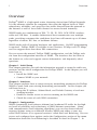
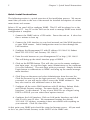
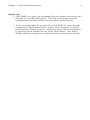
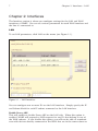
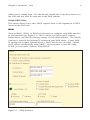
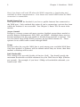
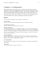
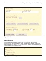
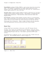
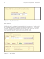
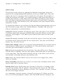
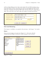
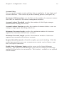
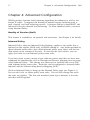
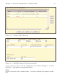
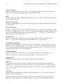
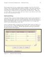
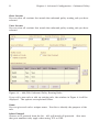
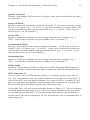
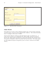
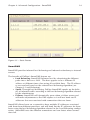
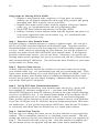
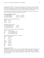
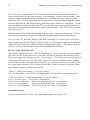
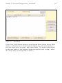
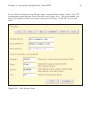
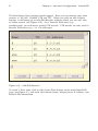
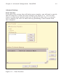
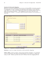
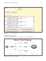
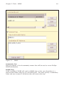
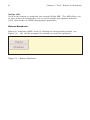
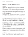
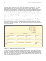
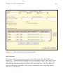
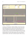
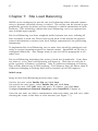
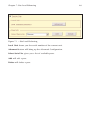
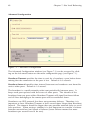
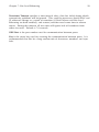
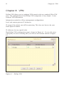
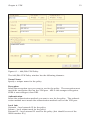
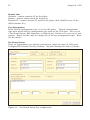
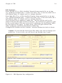
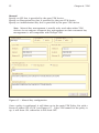
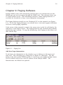
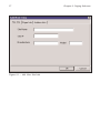
WARP 4.3 User Manual
Table of Contents
Overview . . . . . . . . . . . . . . . . . . . . . . . . . . . . . . . . . . . . . . . . . . . . . . . . . 1
Chapter 1: Initial Setup
Quick Install Instructions . . . . . . . . . . . . . . . . . . . . . . . . . . . . . . . . . . . . . . 4
Chapter 2: Interfaces
LAN . . . . . . . . . . . . . . . . . . . . . . . . . . . . . . . . . . . . . . . . . . . . . . . . . . . . . 7
WAN. . . . . . . . . . . . . . . . . . . . . . . . . . . . . . . . . . . . . . . . . . . . . . . . . . . . . 8
Chapter 3: Configuration
System . . . . . . . . . . . . . . . . . . . . . . . . . . . . . . . . . . . . . . . . . . . . . . . . . . 10
Load Balancing . . . . . . . . . . . . . . . . . . . . . . . . . . . . . . . . . . . . . . . . . . . . 11
Route Test . . . . . . . . . . . . . . . . . . . . . . . . . . . . . . . . . . . . . . . . . . . . . . . . 12
Unit Failover . . . . . . . . . . . . . . . . . . . . . . . . . . . . . . . . . . . . . . . . . . . . . . 13
Users. . . . . . . . . . . . . . . . . . . . . . . . . . . . . . . . . . . . . . . . . . . . . . . . . . . . 15
Chapter 4: Advanced Configuration
Quality of Service (QoS). . . . . . . . . . . . . . . . . . . . . . . . . . . . . . . . . . . . . . 17
Inbound Policy . . . . . . . . . . . . . . . . . . . . . . . . . . . . . . . . . . . . . . . . . . . . 17
Outbound Policy . . . . . . . . . . . . . . . . . . . . . . . . . . . . . . . . . . . . . . . . . . . 20
Static Routes . . . . . . . . . . . . . . . . . . . . . . . . . . . . . . . . . . . . . . . . . . . . . . 23
SmartDNS . . . . . . . . . . . . . . . . . . . . . . . . . . . . . . . . . . . . . . . . . . . . . . . . 24
VPN . . . . . . . . . . . . . . . . . . . . . . . . . . . . . . . . . . . . . . . . . . . . . . . . . . . . 34
Chapter 5: Tools
QoS Statistics. . . . . . . . . . . . . . . . . . . . . . . . . . . . . . . . . . . . . . . . . . . . . . 35
Speed Chart. . . . . . . . . . . . . . . . . . . . . . . . . . . . . . . . . . . . . . . . . . . . . . . 35
Diagnostics . . . . . . . . . . . . . . . . . . . . . . . . . . . . . . . . . . . . . . . . . . . . . . . 37
SNMP . . . . . . . . . . . . . . . . . . . . . . . . . . . . . . . . . . . . . . . . . . . . . . . . . . . 39
Reboot/Shutdown . . . . . . . . . . . . . . . . . . . . . . . . . . . . . . . . . . . . . . . . . . 41
Chapter 6: Quality of Service (QoS) . . . . . . . . . . . . . . . . . . . . . . . . . . . . 42
Chapter 7: Site Load Balancing. . . . . . . . . . . . . . . . . . . . . . . . . . . . . . . . 47
Chapter 8: VPN . . . . . . . . . . . . . . . . . . . . . . . . . . . . . . . . . . . . . . . . . . . . 51
Chapter 9: Paging Software . . . . . . . . . . . . . . . . . . . . . . . . . . . . . . . . . . 56
Technical Support. . . . . . . . . . . . . . . . . . . . . . . . . . . . . . . . . . . . . . . . . . 63
Warranty . . . . . . . . . . . . . . . . . . . . . . . . . . . . . . . . . . . . . . . . . . . . . . . . 64
1
Overview
Overview
FatPipe® WARP is a high-speed router clustering device from FatPipe Networks.
It is the ultimate solution for companies that want the highest levels of WAN
redundancy, reliability, and speed for data traffic directed from the network to
the Internet as well as data traffic directed to servers hosted internally.
WARP bonds any combination of DS3, T1, E3, E1, DSL, OCN, ISDN, wireless,
cable and 56K lines. It enables bidirectional data transmission over multiple
paths, providing customers the confidence data lines will remain up at all times
regardless of router, ISP, line, or backbone failures.
WARP works with all existing hardware and applications. No BGP programming
is required. FatPipe WARP is available in two versions: 50 Mbps and 155 Mbps,
and can support more than three DS3 connections.
You can access the manual, FatPipe WARP configuration, and the FatPipe website from the configuration interface of WARP. The interface also has links to
the feature set, sales and support contact information, and frequently asked
questions.
Chapter 1: Initial Setup
This chapter provides you with the information required to setup the cable connections and the initial configuration for FatPipe WARP. In this chapter you will
learn how to:
• Install the WARP unit
• Connect WARP to your network
Chapter 2: Interfaces
This chapter explains how to setup necessary networking parameters for FatPipe
WARP to work with your existing networking environment. In this chapter you
will learn how to:
• Setup the IP Address, Subnet Mask, and Default Gateway of each networking interface
• Enable or disable access to services running on the WARP unit
• Check the status of each WAN connection
Chapter 3: Configuration
WARP dynamically load balances inbound and outbound IP traffic for the highest levels of reliability and redundancy of WAN/Internet connections. Along
with comprehensive load balancing algorithms, you can also choose failover
recovery options using an additional standby WARP unit either at your site,
called Unit Failover, or at separate locations, called Site Load Balancing. You can
access and configure these options under the Configuration section of the menu.
Information about Site Load Balancing is described in detail in Chapter 7. In
Overview
2
this chapter you will learn how to:
• Set system time
• Choose appropriate Load Balancing option
• Set Route Test configuration
• Setup Unit Failover between two WARP units
• Set user privileges and passwords
• Backup and restore the system configuration
• Reset the system configuration to default settings
Chapter 4: Advanced Configuration
Use the management interface to setup QoS, Inbound Policy, Outbound Policy,
Static Routes, and SmartDNS. In this chapter you will learn how to:
• Configure Quality of Service (QoS) rules for use with Outbound Policy
• Configure Inbound Policy to allow connections to internal servers
• Configure Outbound Policy to specify rules for outbound connections
• Configure Static Routes for additional routed subnets
• Configure SmartDNS for inbound load balancing and redundancy
Chapter 5: Tools
Use FatPipe WARP’s remote management interface to monitor the performance
of your network. You can check the status of routers and Internet connections
using FatPipe WARP’s Diagnostic Tools and view the speed of connections using
the Speed Meter and Speed Chart. In this chapter you will learn how to:
• View the WAN’s performance by using the Speed Chart and Speed Meter
• Check the status of routers and connections using WARP’s Diagnostic
Tools
• View your WAN’s performance with System Statistics
• View QoS Statistics for traffic going through WARP
Chapter 6: Quality of Service (QoS)
WARP can be setup to treat different kinds of traffic differently in respect to priority, latency, and packet loss. You use QoS to do this. QoS is an optional addon feature. Please refer to the contact information in the back of the manual or
contact your local FatPipe representative for purchasing information. In this
chapter you will learn how to:
• Setup and configure QoS
Chapter 7: Site Load Balancing
WARP units can be configured to automatically load balance site traffic to one or
more remote sites, where inbound connectivity to Internet accessible servers is
critical. This technology utilizes Site Load Balancing, and is an optional add-on
feature. Please refer to the contact information on the back of the manual or
contact your local FatPipe representative for purchasing information. In this
chapter you will learn how to:
• Configure Site Load Balancing between two or more units
3
Overview
Chapter 8: VPN
WARP can be setup as a VPN end-point. FatPipe VPN is an optional add-on feature. Please refer to the contact information in the back of the manual or contact your local FatPipe representative for purchasing information. In this chapter
you will learn how to:
• Setup and configure VPN settings
Chapter 9: Paging Software
FatPipe provides monitoring software that can be used to continuously test the
status of your unit. This monitoring software, called Paging Software, will send
you an alert if a failure occurs on the WAN. In this chapter you will learn how
to:
• Install the Paging Software
• Setup and configure the Paging Software
Chapter 1: Initial Setup
4
Chapter 1: Initial Setup
FatPipe WARP is a standard 19” rack mountable device. It has Ethernet interfaces located at the back of the chassis (see Figure 1.1). The LAN interface is
used to connect to your LAN. The other interfaces are used to connect to your
WAN routers. Each of the Ethernet interfaces must be configured to match the
IP addresses of your network by using FatPipe WARP’s remote management
interface (a.k.a. FatPipe WARP GUI – Graphical User Interface).
IMPORTANT: A PREINSTALL WORKSHEET IS INCLUDED IN THE CUSTOMER
PACKET THAT CAME WITH THIS PRODUCT.
WAN 3
WAN 2
WAN 1
LAN
Mouse PS/2
DO NOT USE
Monitor
IF YOU WANT A FATPIPE TECHNICAL SUPPORT ENGINEER TO ASSIST YOU
WITH INSTALLATION, YOU MUST FILL OUT THE PREINSTALL WORKSHEET
AT LEAST 72 HOURS PRIOR TO INSTALL AND FAX IT TO FATPIPE TECHNICAL
SUPPORT AT (801) 281-0317.
Keyboard PS/2
Figure 1.1
1. Unpack WARP from its shipping box.
2. You will receive a 19” rack mountable unit with one power cord.
3. To install WARP you will need one Ethernet network cable for each
interface you will use. You may also need an Ethernet crossover cable
for use in between the LAN interface and a computer for initial configuration.
WARP can be configured and managed remotely through a browser-based management application. You must use Internet Explorer 5.0 (or higher) with the
Java Virtual Machine (JVM) installed to access the remote management interface.
Important:
• Internet Explorer 6.0 installs the JVM automatically. Other versions may
not install the JVM by default. Please make sure your browser has the
latest JVM installed. Visit www.microsoft.com/java to find information
on installing Microsoft’s JVM.
• If you will be accessing the remote management interface from behind a
firewall, make sure TCP port 5001 is allowed for outbound connections.
Also make sure Java applets are allowed through the firewall.
5
Chapter 1: Quick Install Instructions
Quick Install Instructions
The following section is a quick overview of the installation process. We recommend that you refer to the rest of the manual for detailed descriptions of various
menu items and screens.
Select a PC on your LAN to configure WARP. This PC will be referred to as the
Management PC. Any PC on the LAN can be used to manage WARP once initial
configuration is complete.
1. Connect the WARP unit to a UPS outlet. Power the unit on. It takes less
than a minute to boot up.
2. Connect the LAN interface to your local network and the WAN interfaces
to your WAN routers. Initial configuration must be done through the
LAN interface.
3. Configure the Management PC with IP address 192.168.0.10, Subnet
Mask 255.255.255.0, and Gateway 192.168.0.1.
4. Point the web browser on your Management PC to http://192.168.0.1
This will bring up the initial interface page of WARP.
5. Click on the ENTER button. This will take you to the remote configuration login page. At your first login, enter Administrator as the username
(it is case-sensitive). The unit ships with no password. Simply click the
Login button to authenticate to WARP and bring up the remote management interface.
6. Click Users on the menu and select Administrator from the user list.
Click Set Password to set the login password. Be sure to remember this
password, as you will not be able to access the WARP without it. You
may also want to add additional users at this time.
7. Configure all the active WAN interfaces with IP Address, Subnet Mask,
and Default Gateway settings. For more details, see “Chapter 3:
Interfaces” in this manual. If any of your WAN IPs are assigned using
DHCP or PPPoE, you can select those options instead.
8. Configure the LAN interface: Click on LAN under Interfaces and click
Add to add a new IP alias. We recommend keeping the default
192.168.0.1 IP address, assuming it does not conflict with anything on
your network. Click Ok, then Save.
At this point your WARP unit should be setup for Internet access. All you need
to do is set your Default Gateway to the LAN IP of the WARP unit.
Chapter 1: Quick Install Instructions
6
Helpful Tips:
• Once WARP is in place, we recommend that you reboot your routers and
firewalls to clear their ARP caches. This will assure proper network
communication between WARP and your other network devices.
•
If you are using public IPs on the LAN side of WARP in a pass-through
configuration (see Inbound Policy), it may not be necessary to change
your network’s Default Gateway. WARP uses Proxy ARP to automatically forward packets destined for any of the WAN routers. This makes
WARP completely transparent to internal devices accessing the Internet.
7
Chapter 2: Interfaces - LAN
Chapter 2: Interfaces
The Interface section is where you configure settings for the LAN and WAN
interfaces of WARP. You can set various parameters for each WAN interface and
the line it’s connected to.
LAN
To set LAN parameters, click LAN on the menu (see Figure 2.1).
Figure 2.1 – LAN Interface
You can configure one or more IPs on the LAN interface. Simply specify the IP
and Subnet Mask for each IP subnet connected to the LAN interface.
Enable Proxy ARP
This will enable or disable Proxy ARP on the LAN side. When this option is
enabled, WARP will respond to ARP requests for any IPs that belong to any of
the WAN subnets. If you disable this option, you will not be able to communicate with devices directly connected to the WAN that are in the same subnet as
Chapter 2: Interfaces - LAN
8
where you’re coming from. You should only disable this if you have devices on
the LAN side that have IPs from one of the WAN subnets.
Enable DHCP Relay
This option allows you to relay DHCP requests from a LAN segment to a DHCP
server on the WAN side.
WAN
Click on WAN1, WAN2, or WAN3 on the menu to configure each WAN interface
in your network (see Figure 2.2). This is where you can assign IP Address,
Subnet Mask, and Default Gateway settings to each WAN interface. The Default
Gateway is typically the Ethernet IP address of your WAN router. If your WAN
IP settings are assigned dynamically by a DHCP server, you can select “Obtain
an IP address automatically using DHCP”. If you connect to your ISP using
PPPoE, you can select “Connect using PPPoE”.
Figure 2.2 – WAN Interface
9
Chapter 2: Interfaces - WAN
Note: Line Status will read UP when the WAN connection is functioning and
available for data communication. Line Status will read DOWN when the WAN
connection is unavailable.
Enable Route Test
This option should be checked if you have a public Internet line connected to
the WAN port. Only uncheck this option if you’re connecting a private line from
which the Internet is not accessible. See Chapter 3, Route Test for more information.
Access Control
FatPipe is a secure system with most services disabled except those needed to
provide Remote Management, SSH, DNS, and SNMP. Although these services
present minimal risk, you can enable or disable these features as desired. You
can also block Ping (ICMP ECHO) requests for the WAN interface IP. These
options do not affect traffic routed through WARP.
Usage
You can select the way this WAN line is used among your available WAN lines.
Only lines marked as Primary will be utilized unless they are down, then lines
marked as Backup will be used.
Link Bandwidth
This setting is for use with Quality of Service (QoS). You should specify the
maximum bandwidth available outbound for your WAN line in Kbps (Kilobits
per second). For example, if you have 1.5Mbps of bandwidth outbound, you
would enter 1500.
Chapter 3: Configuration - System
10
Chapter 3: Configuration
The Configuration section allows you to configure basic parameters of your
WARP unit. Under the Configuration menu, you can choose a load balancing
method for inbound and outbound IP traffic, set route test configurations, setup
failover between multiple WARP units at the same location (Unit Failover) or
setup load balancing between multiple WARP units at separate locations (Site
Load Balancing – please refer to Chapter 7 for details). The Configuration section is also where you can set user privileges and user passwords.
System
Click System to configure system settings (see Figure 3.1).
System Name
You can set a Host Name and Domain name to identify the system.
System Date and Time
You can set the date and time for the system.
Backup and Restore
You can backup or restore configuration settings. If you click Backup Settings
you will be prompted to save a backup configuration file. If you click Restore
Settings you will be prompted to import a previously saved backup configuration
file. If you click Restore Defaults you will be prompted to restore the system
back to factory defaults
Session Timeouts
You can specify TCP and UDP idle timeouts for connections routed through
WARP. The defaults are 120 minutes (2 hours) for TCP and 3 minutes for UDP.
Rarely do you need to change these settings.
Set Login Banner
You can specify a message that will be displayed on the Remote Configuration
login page.
Clear ARP
Use this to clear the system’s ARP cache.
11
Chapter 3: Configuration - Load Balancing
Figure 3.1 – System
Load Balancing
FatPipe WARP provides three methods of load balancing: Round Robin,
Response Time, and Fastest Route. Click Load Balancing to bring up the Load
Balancing page (see Figure 3.2). You can also set Primary and Backup lines per
WAN interface (see Chapter 2, WAN).
Figure 3.2 – Load Balancing
Chapter 3: Configuration - Route Test
12
Round Robin configures FatPipe WARP to send sessions down lines in rotating
order. This method is recommended for similar speed connections to the
Internet, even if the connections are not of the same kind (e.g., combining two
similar speed fractional T1s and a DSL line).
Response Time configures FatPipe WARP to balance traffic based on each line’s
average response time for Internet requests. This method is recommended for
unequal speed connections. The fastest line will be used more often with
Response Time.
Fastest Route configures FatPipe WARP to balance traffic on a per-destination
basis. Each session will go over the fastest line for its destination. Choose this
option when you want to make sure each session goes out the line with the
fastest route for its destination. (There is slight overhead with this algorithm
since SYN packets get sent out all lines at the start of each session).
Route Test
FatPipe WARP tests connections to the router, to the ISP (Internet Service
Provider), and to three user-specified sites on the Internet. Each site can be
specified using a domain name or an IP address. The port number should be a
valid listening TCP port at the site. The default is port 80 for HTTP (web
servers).
Click Route Test to configure test sites. You can add, edit, or delete sites (see
Figure 3.3). The Add/Edit window is shown in Figure 3.4.
Figure 3.3 – Route Tests
13
Chapter 3: Configuration - Route Test
Figure 3.4 – Add/Edit Route Test
Unit Failover
WARP units can be configured to automatically fail over in case of hardware failure. This helps to maintain a reliable and redundant connection to the Internet.
Two units are required to implement Unit Failover. At any given time, one will
be in an Active state and the other will be in a Standby state
(see Figure 3.5). Only the current Active unit will route traffic.
Figure 3.5 – Unit Failover
Chapter 3: Configuration - Unit Failover
14
Initial Setup
The physical setup consists of splitting the Ethernet connections from each
router to the corresponding WAN interfaces of the two WARP units. This will
require the use of a separate switch (or hub) for each router. For example, to
setup the hardware for WAN1, you would connect a cable from the router to a
switch, then connect a cable from each of the WAN1 interfaces to the switch.
This will allow communication between the router and both WAN1 interfaces.
You would do the same between your LAN interfaces and your internal device
(firewall or router).
To enable Unit Failover, you will need to log into Remote Management and go to
the Unit Failover page. Select the “Enable Failover” checkbox and enter the
failover information as described below.
Group ID uniquely identifies the failover group. This only needs to be changed
if you have more than one pair of WARP units using Unit Failover on the same
network. Valid range is 1-255. Both of your failover units must use the same
Group ID.
Access IP uniquely identifies each unit and will be used to access the unit when
in Standby mode (when all other IPs are deactivated). You must use IP/Mask
format (e.g. 192.168.0.10/24).
Email Alert Settings allows you to specify email information so an email can be
sent whenever failover occurs (see Figure 3.6). This email will be sent from a
unit that goes from Standby to Active state.
Role indicates the preferred role of each unit. One unit will be set as Primary
and the other as Backup. The role only applies when both units are powered on
at the same time. The unit marked Primary will go to the Active state and the
unit marked as Backup will go to the Standby state.
State shows the current failover state of the unit you are logged into, either
Active or Standby.
Force to Standby will allow you to force an Active unit to Standby mode, allowing the other unit to become Active.
Backup Unit shows details about any unit that is detected as a backup to the
one you are viewing. The IP address is the backup unit’s Access IP. The State
could be displayed as Active, Backup, or Down. If it’s marked as Down, it means
the unit is no longer detected.
At a minimum, you must specify a Group ID and Access IP. When you click
Save, you will be prompted to reboot. Once the WARP unit has rebooted, you
15
Chapter 3: Configuration - Users
will be in Unit Failover mode. Since each of the LAN and WAN interfaces use a
new virtual MAC address, you may not be able to access the unit until the ARP
cache has cleared on any devices between you and the WARP unit. You could
either run a command to clear the ARP caches on those devices or simply reboot
them. This only needs to be done when you enable or disable Unit Failover.
Figure 3.6 – Email Alert Settings
Site Load Balancing
This feature is available as an optional add-on feature. See Chapter 7 for details.
Users
Here you can manage your users (see Figure 3.7). Only users with the
Administrator privilege are allowed to make changes to user accounts.
Figure 3.7 – Users
Chapter 3: Configuration - Users
16
Account Policy
You can specify account security policies that are applied to all new logins and
account creations. This is made up of the following policies (see figure 3.8):
Maximum GUI Connections sets the limit on the number of concurrent connections that are allowed to the remote management interface.
Account Lockout Threshold specifies the number of failed login attempts
allowed before locking out the user.
Account Lockout Duration specifies the number of minutes before a user can
attempt to login again after being locked out.
Minimum Username Length specifies the minimum number of characters
required for usernames for new user accounts.
Minimum Password Length specifies the minimum number of characters
required for passwords for new user accounts.
Require Mixed Passwords will enable complex password checking. With this
enabled passwords for new user accounts must contain a mix of letters, numbers, and special characters.
Enable Central Manager Login provides access to the Central Manager
Software. The FatPipe Central Manager is the tool you would use to manage
multiple FatPipe boxes via one interface. This feature is available as an optional
add-on feature.
17
Chapter 4: Advanced Configuration - QoS
Chapter 4: Advanced Configuration
WARP provides dynamic load balancing algorithms for inbound as well as outbound IP traffic. It supports the hosting of internal servers including web, email, firewall, and load balancing servers. It features FatPipe’s SmartDNS™ and
Inbound Policy for inbound load balancing. To allow inbound traffic, you must
setup Inbound Policy.
Quality of Service (QoS)
This feature is available as an optional add-on feature. See Chapter 6 for details.
Inbound Policy
Inbound Policy, short for Inbound Policy Routing, applies to any traffic that is
initiated on the outside (WAN side) of WARP coming in. Any traffic matched by
these inbound traffic rules (also called inbound policy route rules) will be handled based on the settings of the rule. If you have the QoS add-on, you can
apply QoS rules to your inbound policy route rules.
If you have used a prior version of our software, please note that we have now
combined the functionality of Pass-Through and Reverse Mapping into one page
called Inbound Policy. This change was necessary to facilitate the use of QoS
with inbound policy route rules. Each rule can be configured to forward traffic
inbound with or without doing Reverse Mapping (NAT).
Click on Inbound Policy to bring up the Inbound Policy page (see Figure 4.1).
You can add, edit, or delete policy route rules. You can also change the order
the rules are applied. The first rule matched (from top to bottom) is the only
rule that will be applied.
Chapter 4: Advanced Configuration - Inbound Policy
18
Figure 4.1 – Inbound Policy Routing
Figure 4.2 – Add/Edit Inbound Policy Routing Rule
If you add a new rule or edit an existing rule, the window in Figure 4.2 will be
displayed. The options are explained below.
Name
You can give each rule a unique name. Use this to identify the purpose of the
rule.
19
Chapter 4: Advanced Configuration - Inbound Policy
Select Protocol
Choose an IP protocol from the list. ALL will match all protocols. Also note
that port numbers only apply when using TCP or UDP.
Rule
Choose Allow to allow traffic that matches the rule. Choose Deny to deny traffic
that matches the rule.
Quality of Service
Choose a pre-defined QoS rule that will apply to the traffic matched by this policy route rule.
Source IP/Mask
Specify a source IP and mask (using bit notation). If you want to match a singe
IP, use a /32 mask (e.g., 1.2.3.4/32). If you want to match an entire subnet, use
the network number with the network mask (e.g., 1.2.3.0/24). If you want to
match any IP, use an asterisk (*).
Source Port
Specify a single port number or a port range separated by a hyphen (e.g., 11023). If you want to match any port number, use an asterisk (*).
Destination IP/Mask
Specify a destination IP and mask (using bit notation). If you want to match a
singe IP, use a /32 mask (e.g., 1.2.3.4/32). If you want to match an entire subnet, use the network number with the network mask (e.g., 1.2.3.0/24). If you
want to match any IP, use an asterisk (*).
Destination Port
Specify a single port number or a port range separated by a hyphen (e.g., 11023). If you want to match any port number, use an asterisk (*).
Enable NAT
Check this if you want to NAT traffic that matches this rule.
NAT IP
Specify the IP and subnet mask (using bit notation) that the traffic will be
mapped to. If you want to map the traffic to a single IP, use a /32 mask (e.g.,
1.1.1.1/32). If you want to map the traffic one-to-one, use a full subnet mask
(e.g., 1.1.1.0/24).
NAT Port
Specify the port number the traffic will be mapped to. If you want to map all
ports, use an asterisk (*).
Please note that if you do not select NAT, then the rule will default to PassThrough, which means that WARP simply forwards traffic matching the rule.
Chapter 4: Advanced Configuration - Outbound Policy
20
This requires that you use a smaller subnet, typically a /30 (255.255.255.252)
subnet, on the corresponding WAN interface of WARP. The router, firewall, and
any other device with a public IP will be assigned the full subnet mask. The
LAN interface of WARP will also be assigned the full subnet mask. WARP will
use Proxy ARP to receive the traffic and route it back to the LAN for any IPs that
are part of the Destination IP/Mask.
Outbound Policy
Outbound Policy, short for Outbound Policy Routing, applies to any traffic that is
initiated on the inside (LAN side) of WARP going out. Any traffic matched by
these outbound policy route rules will be treated differently than the default load
balanced and NATed traffic. If you have the QoS add-on, you can apply QoS
rules to your outbound policy route rules.
Click on Outbound Policy to bring up the Outbound Policy page (see Figure 4.3).
You can add, edit, or delete outbound policy route rules. You can also change
the order the rules are applied. The first rule matched (from top to bottom) is
the only rule that will be applied.
Figure 4.3 – Outbound Policy Routing
21
Chapter 4: Advanced Configuration - Outbound Policy
Clear Session
You can clear all sessions that match the outbound policy routing rule you have
selected.
View Session
You can view all sessions that match the outbound policy routing rule you have
selected.
Figure 4.4 – Add/Edit Outbound Policy Routing Rules
If you add a new rule or edit an existing rule, the window in Figure 4.4 will be
displayed. The options are explained below.
Name
You can give each rule a unique name. Use this to identify the purpose of the
rule.
Select Protocol
Choose an IP protocol from the list. ALL will match all protocols. Also note
that port numbers only apply when using TCP or UDP.
Chapter 4: Advanced Configuration - Outbound Policy
22
Quality of Service
Choose a pre-defined QoS rule that will apply to the traffic matched by this policy route rule.
Source IP/Mask
Specify a source IP and mask (using bit notation). If you want to match a singe
IP, use a /32 mask (e.g., 1.2.3.4/32). If you want to match an entire subnet, use
the network number with the network mask (e.g., 1.2.3.0/24). If you want to
match any IP, use an asterisk (*).
Source Port
Specify a single port number or a port range separated by a hyphen (e.g., 11023). If you want to match any port number, use an asterisk (*).
Destination IP/Mask
Specify a destination IP and mask (using bit notation). If you want to match a
singe IP, use a /32 mask (e.g., 1.2.3.4/32). If you want to match an entire subnet, use the network number with the network mask (e.g., 1.2.3.0/24). If you
want to match any IP, use an asterisk (*).
Destination Port
Specify a single port number or a port range separated by a hyphen (e.g., 11023). If you want to match any port number, use an asterisk (*).
Traffic Mode
Interface Priority directs traffic out the first live line, using the WAN interface
order you specify. Interface Specific directs traffic out only the specified line(s).
WAN Interface List
You can enter a list of WAN interfaces that you want this policy route rule to
use. For each interface you can specify whether or not you want to do NAT. If
you do use NAT, you can specify whether you want to NAT to a specific IP and
port or if you want to have the system automatically assign an IP and port (the
IP will be the IP of the WAN interface the traffic goes out).
If you click Add, you will see the window shown in Figure 4.5. First you choose
the WAN interface you want to use. Then you select whether or not you want
to use NAT and/or Port NAT. If you choose the Auto options, the system will
handle the IP and port assignments for you dynamically (this is recommended in
most scenarios).
23
Chapter 4: Advanced Configuration - Static Routes
Figure 4.5 – Add/Edit WAN Parameters
Static Routes
Static Routes are used to route additional subnets that are not locally connected
(in other words, not part of one of the Interface subnets). This section describes
how to configure static routes in WARP.
Click on Static Routes to bring up the Static Routes page (see Figure 4.6). A
static route is made up of a destination IP, subnet mask, gateway, and metric.
The IP and subnet mask determine the range of IP addresses that will be routed.
The gateway determines where the packets will be forwarded. The metric specifies the number of hops to the gateway (and is at least 2 with the way WARP
routes).
Chapter 4: Advanced Configuration - SmartDNS
24
Figure 4.6 – Static Routes
SmartDNS
SmartDNS provides inbound load balancing and inbound redundancy to internal
servers.
The benefits of FatPipe’s SmartDNS feature are:
• Load Balancing: SmartDNS balances load by advertising the different
paths into a host on a LAN. The host appears to be a different IP
address at different times, thus using all available lines. The IP addresses are resolved based on the selected load balancing algorithm (see
Chapter 3: Load Balancing).
• Speed: Through load balancing, FatPipe SmartDNS speeds up the delivery of inbound traffic according to the load balancing algorithm selected
by the administrator.
• Failover: SmartDNS will dynamically sense when a failure occurs and
will make adjustments to the DNS replies so it will not hand out IP
addresses that are associated with connections that are down.
SmartDNS allows hosts on a network to have multiple IP addresses associated
with them from different providers, and will hand out the IP addresses for these
hosts using the load balancing algorithm selected in the Load Balancing configuration. SmartDNS tests the different connections and can detect when connections fail.
25
Chapter 4: Advanced Configuration - SmartDNS
Setup Steps for Moving DNS to WARP
1. Register a new domain with a registrar, or if you have an existing
domain, get all domain information from your DNS provider (the group
managing your DNS, typically one of your ISPs).
2. Register new name server names with the registrar using your domain
name (e.g., ns1.yourdomain.com and ns2.yourdomain.com).
3. Setup DNS Zone (domain information) on FatPipe WARP.
4. Initiate a transfer of your domain name with the registrar and point it to
your newly registered name server names (e.g., ns1.yourdomain.com
and ns2.yourdomain.com).
Step 1: Register a New Domain Name
You must contact a domain registrar to register a domain name. You can get a
full list of ICANN-accredited registrars from InterNIC.com. Directnic.com and
Networksolutions.com are two of the competing ICANN-accredited registrars you
can use. In the course of registering the new domain, you may be required to
provide two name servers that will handle your domain name. If the registrar
provides default name servers, you can use them. Otherwise, just specify any
existing name servers (perhaps just put in ns.yahoo.com and ns1.yahoo.com and
their corresponding IP addresses). You will transfer these domains to your name
server names in a future step.
Step 2: Register Name Servers
Contact your registrar to initiate the creation of your new name servers using
your domain name (e.g., ns1.yourdomain.com and ns2.yourdomain.com). Each
name server name will map to its own WAN port IP address on WARP. As far as
the registrar knows, your domain name is handled on multiple physical name
servers, but in reality you are simply mapping a different name server name to
each of the WAN port IP addresses.
Step 3: Set Up DNS Zone (Domain Information)
To achieve inbound redundancy, each domain name record (e.g., www) will
have multiple IP addresses assigned to it — one from each WAN IP block.
SmartDNS will hand out these IP addresses based on the type of load balancing
you have set WARP to use. If you choose Round Robin or Fastest Route, the IP
addresses are handed out in a round-robin fashion. If you choose Response
Time, packets will be handed out based on the response time of each WAN line.
If you use On Failure, only IP addresses from the designated primary WAN lines
are handed out. If you specify two primary WAN lines, then the two IP addresses associated with those lines are handed out in a round-robin fashion.
Step 4: Initiate Zone Transfer
The last step is to change the name servers for your domains at your registrar’s
website. This is commonly referred to as “initiating a zone transfer”. You will
change the name servers for your domains to the name servers you registered in
Step 2. The transfer will take a day or two. Once the transfer is complete and
the root name servers are updated with the new name server information,
Chapter 4: Advanced Configuration - SmartDNS
26
SmartDNS will be live. There may be name servers out in the world that have
information cached for a week or more though, so make sure you do not take
down your pre-existing name servers. We recommend you keep those in place
for at least two weeks or even a month if you want to be extra careful.
Eventually nobody will be using your pre-existing name servers and it will be
safe to remove your domains from those servers.
Basic SmartDNS Example
1st WAN IP Block
7.0.0.0 – 7.0.0.255
2nd WAN IP Block
8.0.0.0 – 8.0.0.255
3rd WAN IP Block
9.0.0.0 – 9.0.0.255
IP Addresses on FatPipe WAN Ports
WAN1 7.0.0.2
WAN2 8.0.0.2
WAN3 9.0.0.2
Registered Name Servers
ns1.yourdomain.com
ns2.yourdomain.com
ns3.yourdomain.com
7.0.0.2
8.0.0.2
9.0.0.2
SmartDNS Name Server Entries (NS records)
Name Name Server
@
ns1.yourdomain.com
@
ns2.yourdomain.com
@
ns3.yourdomain.com
SmartDNS Host Name Entries (A records)
Name IP Address
@
7.0.0.5
@
8.0.0.9
@
9.0.0.44
www
7.0.0.5
www
8.0.0.9
www
9.0.0.44
ftp
7.0.0.7
ftp
8.0.0.35
ftp
9.0.0.19
Time to Live (TTL)
SmartDNS uses a short TTL to ensure the information about the IP addresses for
the hosts it serves are accurate and up-to-date. This means that the machines
on the Internet will always connect to the host using a route that is available
instead of trying to access the host using an IP address that is not accessible due
to a line failure.
27
Chapter 4: Advanced Configuration - SmartDNS
The TTL value informs all DNS servers on the Internet how long they should
store information about your domain. For example, a name server caches your
domain information following a request for a website that uses your domain.
Until the TTL value is exceeded, that name server will continue using the information supplied by the first request each time your domain is requested. When
your domain is requested after the TTL period, the name server will conduct a
new query for updated information about your domain. The TTL value is measured in seconds.
WARP ensures that DNS information is up-to-date. You can change the TTL to
your own preferences, along with Refresh, Expire, and Retry entry settings.
You can set TTL, Refresh, Expire, and Retry settings by entering the corresponding information in the Master Zone Defaults by clicking through the SmartDNS,
Create Master, and Create Master Zone configuration pages. You must click on
SAVE to activate all changes made to the SmartDNS settings.
Reverse DNS (PTR Records)
SmartDNS supports Reverse DNS (PTR Records). To set this up, you must know
the exact name of the zone that your ISP will use to delegate the Reverse DNS.
The zone name will always end in “in-addr.arpa”. The only valid record types in
a Reverse DNS zone are NS and PTR. There are several different zone naming
conventions used to delegate Reverse DNS, so you must contact your ISP to find
out what zone name to enter under SmartDNS. Here are some examples showing common zone naming conventions:
“Class C” delegation using 1.2.3.0/24 subnet:
3.2.1.in-addr.arpa – notice that it begins with the first three octets backwards
“Less than Class C” delegation using 1.2.3.0/25 subnet:
0.3.2.1.in-addr.arpa – “first octet” convention
0/25.3.2.1.in-addr.arpa – “first octet slash mask bits” convention
0-25.3.2.1.in-addr.arpa – “first octet dash mask bits” convention
0-127.3.2.1.in-addr.arpa – “first octet dash last octet” convention
SmartDNS Setup
Click on SmartDNS to access the SmartDNS page (see Figure 4.7).
Chapter 4: Advanced Configuration - SmartDNS
28
Figure 4.7 – SmartDNS
Click on the Create Master button to input Domain Name, Master Server, EMail
Address, and Name Server information (see Figure 4.8). You must specify at
least one name server to create a new domain/zone. The name servers should
be the same names as you registered with your registrar (refer to Step 2 under
the “Setup Steps for Moving DNS to WARP”).
29
Figure 4.8 – Create Master Zone
Chapter 4: Advanced Configuration - SmartDNS
Chapter 4: Advanced Configuration - SmartDNS
30
To set default values for the Master Zone, enter Refresh, Retry, Expire, and TTL
information under Master Zone Defaults (see Figure 4.9). We recommend you
keep the defaults unless you know what you’re doing. Click OK to save the
zone.
Figure 4.9 – Edit Master Zone
31
Chapter 4: Advanced Configuration - SmartDNS
The Edit Master Zone window should appear. Here you can manage your zone
records: A, NS, MX, CNAME, PTR and TXT. When you click on one of those
buttons, it will bring up an Add/Edit Records window where you can add, edit,
or delete records (see Figure 4.10). On a Forward DNS zone (e.g.,
example.com), you will never specify PTR records. PTR records are only used in
Reverse DNS zones (e.g., 3.2.1.in-addr.arpa).
Figure 4.10 – Add/Edit Records
To create a slave zone, click on the Create Slave button on the main SmartDNS
page (see Figure 4.7) and enter the Domain Name, Master Server IP address, and
Records File information.
Chapter 4: Advanced Configuration - SmartDNS
32
Advanced Settings
Zone Transfers
If you have slave servers that will initiate zone transfers, you will need to specify
their IP addresses to allow the zone transfers (see Figure 4.11). You can also
choose to allow zone transfers from any IP, but this is often seen as a security
risk as anybody can view an entire zone by performing a zone transfer from
their computer.
Figure 4.11 – Zone Transfers
33
Chapter 4: Advanced Configuration - SmartDNS
Interface-To-Network Mappings
Interface-To-Network Mappings are necessary for SmartDNS to function properly.
The mappings are used to specify the network(s) that belong to each interface
(see Figure 4.12). This will tell SmartDNS which IPs belong to which interfaces
when answering DNS queries. The mappings are also used with Site Load
Balancing (see Chapter 7) to specify which networks belong to each interface of
each site.
Figure 4.12 – Interface-To-Network Mappings
Interface is used to assign an Interface to this particular mapping.
Select a Role is used to assign a role to this particular mapping. It is primarily
used in conjunction with Site Load Balancing but can be used in a single unit
setup as well. Primary specifies that an IP address from the mapping will be
Chapter 4: Advanced Configuration - VPN
34
handed out in a DNS request as long as the line for the associated interface is
up. Backup specifies that an IP address from the mapping will be handed out in
a DNS request only if all Primary mappings are unavailable (meaning the lines
for their associated interfaces are down).
Weight affects how often IPs from this particular mapping are handed out in
DNS requests. The number entered is the number of times an IP will be handed
out before using the next mapping. If all mappings have a weight of one, then
they are all treated equal and IPs are handed out in a round-robin fashion.
View Statistics
You can view a record of SmartDNS statistics for all the zones, which tabulates
the DNS responses based on the IP Addresses.
Clear Statistics
You can clear all the SmartDNS statistics stored.
VPN
This feature is available as an optional add-on feature. See Chapter 8 for details.
35
Chapter 5: Tools - Speed Chart
Chapter 5: Tools
FatPipe WARP provides graphical monitoring tools to aid you in monitoring the
speed and performance of your Internet connections. This chapter describes the
methods to view the Speed Chart and the Speed Meter. If you have the QoS
add-on, then you will also see a QoS Statistics page, that page is covered in
Chapter 6.
Speed Chart
Monitor the upload and download or combined speeds of each of the WAN lines
independently or in combination by viewing the Speed Chart. To view the chart,
click Speed Chart (see Figure 5.1).
There are five views to choose from:
• WAN1 - Displays Total Speed, Upload Speed, and Download Speed for
WAN1
• WAN2 - Displays Total Speed, Upload Speed, and Download Speed for
WAN2
• WAN3 - Displays Total Speed, Upload Speed, and Download Speed for
WAN3
• ALL INTERFACES TOGETHER - Displays Total Speed, Total Upload
Speed, and Total Download Speed of all WAN ports combined
• ALL INTERFACES - Displays Total Speed for each of the WAN ports on
the same graph
The Speed Chart is a dynamic, real-time chart that updates every second. The
scale dynamically changes based on the current bandwidth usage. Also included in some views is Speed Meters which show you the same information, just in
a different way.
Chapter 5: Tools - Speed Chart
Figure 5.1 – Speed Chart
36
37
Chapter 5: Tools - Diagnostics
Diagnostics
FatPipe WARP can test both physical and Internet service connections for availability. Select the Diagnostics page to run various tests.
You can ping a host or trace route to a host to test connectivity (see Figure 5.2).
Enter the IP address or domain name of the host, which can be a router, server,
or any IP-enabled device. You can also select which interface to run these tests
from.
Figure 5.2 - Diagnostics
Show System Statistics
Display information about WARP including system uptime and interface statistics
(e.g., packets received, packets transmitted, and any packet errors see Figure
5.3).
Chapter 5: Tools - Diagnostics
Figure 5.3 – System Statistics
Show Route Test Display
Display a graphical display of current line status (see Figure 5.4).
Figure 5.4 – Route Test Display
38
39
Chapter 5: Tools - SNMP
Show Traffic Logging Info
Display a page where you can monitor the inbound and outbound traffic for
individual hosts on your network. You can click the host name or host IP to
view a history graph for that host.
Session Information
You can view all the sessions currently running on the unit.
SNMP
FatPipe products support SNMPv2 (Simple Network Management Protocol version 2) with MIB-II (Management Information Base II) compliance, to accommodate SNMP queries in addition to sending out SNMP traps. This allows you to
use SNMP management software to monitor and gather statistics from FatPipe
products and view and monitor system parameters of your FatPipe unit.
Please note that FatPipe SNMP is read-only. Write access is not currently supported.
You configure SNMP settings from within the web-based management application. Once SNMP is configured, you can monitor the FatPipe unit using any
SNMP manager. Click on SNMP to bring up the SNMP page (see Figure 5.5).
Chapter 5: Tools - SNMP
40
Figure 5.5 – SNMP
Community List
Here you specify a list of community names that will be used to access FatPipe
SNMP information.
Enable Trap
If this is enabled, WARP will send an SNMP trap to alert you when there is a
physical link failure with any of your WAN lines. You must specify a community
name and one or more IP addresses that will receive the trap.
41
Chapter 5: Tools - Reboot or Shutdown
FatPipe MIB
Click on this button to download our custom FatPipe MIB. This MIB allows you
to view almost all settings that you see in the remote management interface
(GUI) from within an SNMP management application.
Reboot/Shutdown
Reboot or shutdown WARP safely by clicking the corresponding button (see
Figure 5.6). You will be prompted to confirm or cancel the operation.
Figure 5.6 – Reboot/Shutdown
Chapter 6: Quality of Service (QoS)
42
Chapter 6: Quality of Service (QoS)
Introduction
QoS is an add-on feature from FatPipe. When enabled, it allows you to prioritize
your WAN traffic. This is especially useful for ensuring that real-time traffic
(e.g., voice and video) gets priority over other types of traffic.
The primary purpose of QoS is assurance that packets are transported from a
source to a destination with certain characteristics, corresponding to the requirements of the service that the packet flow supports. This becomes a challenge in
a situation where multiple streams compete for limited available resources. One
of these resources is link transmission capacity, which gets divided into
throughputs of individual streams. Another important resource is buffer memory, which affects packet loss.
Outgoing network traffic is managed by assigning a priority to each type of traffic. This priority determines the treatment of that traffic type in terms of how
many packets are preserved and how urgently they are transmitted, relative to
one another.
A1 is the highest priority and Best Effort (BE) traffic is the lowest classification.
The Best Effort classification does not guarantee any particular level of service; it
simply represents the unused capacity of the link at any moment. In addition to
QoS priority, a certain amount of bandwidth is also assigned by the user to each
type of traffic, and it is defined by committed rate (CR) and burst rate.
Committed rate of a traffic type defines the amount of bandwidth that is guaranteed to be available for that type of traffic at any time the associated link is up.
The amount of traffic forwarded under these conditions is called the primary
rate. Burst rate defines upper limit for bandwidth that can be made available to
the traffic type. The burst rate defaults to the maximum available bandwidth of
the associated interface and cannot be changed. The amount of bandwidth
between CR and burst rate is made available only if it is not in use by other
quality groups. Traffic above CR is downgraded to Best Effort, without guarantees on packet loss and delay.
FatPipe QoS also provides some degree of control over incoming network traffic
by letting the user limit the rate at which the LAN receives traffic from each of
the WAN links. While this does not help conserve bandwidth, it can help
reduce the occurrence of unwanted connection-oriented traffic. The Inbound
Policed Rate defines the limit above which all incoming traffic that it applies to
will be dropped.
Configuration
In order to define QoS characteristics for a traffic type, you first must create a
QoS Rule. Go to the Quality of Service page and click Add (see Figure 6.1).
43
Chapter 6: QoS Configuration
Enter the name for the rule (only letters and numbers are allowed). For each
link (interface) that you want to use for this type of traffic, you can define
Inbound Policed Rate and/or Committed Rate. Note that Link Bandwidth has to
be defined for each link that you want to apply the QoS rules to (see Chapter 2:
Interfaces). The minimum value for Committed Rate (CR) is 8 kbps and the
maximum value is 90% of the link bandwidth. The actual amount available to
a particular quality group depends on the amount of bandwidth that has already
been committed. Sum of all CRs on a particular link cannot be greater than
90% of the Link Bandwidth. The remaining 10% is always reserved for Best
Effort traffic.
Burst rate cannot be changed and defaults to the link bandwidth. The QoS
Rules table provides a convenient view of Inbound Policed Rates, Committed
Rates, and Priorities, as well as Link Bandwidths and total bandwidth already
reserved by CRs for each link. You can select from 10 different priority levels for
each type of traffic.
Figure 6.1 – Add/Edit Quality of Service Rule
A QoS rule by itself does nothing without an association with a particular kind
of traffic. In order to create this association, go to either the Outbound Policy or
Inbound Policy page. If you edit an existing Policy Routing rule or create a new
one, you can select a QoS rule which will be applied to the traffic defined by the
Policy Routing rule (see Figure 6.2).
Chapter 6: QoS Configuration
44
Figure 6.2 – Edit Outbound Policy Routing Rule
QoS Statistics
This page displays information about QoS traffic going through WARP (see
Figure 6.3). Information is displayed on two real-time charts. The chart at the
top displays the rate at which traffic is being forwarded. The chart at the bottom displays the percentage of packets that are being lost. You can filter the
view by selecting a QoS Rule, one or more interfaces and a direction (either
inbound or outbound).
45
Chapter 6: QoS Configuration
Figure 6.3 – QoS Statistics
In order to see information for a particular QoS Rule, you first need to select a
QoS Rule from the QoS Rule list. When a QoS Rule is selected, interfaces that
the rule applies to will appear in the list box to the right. Select one or more
interfaces for which you want to monitor traffic in the interface list and move
them to the selected list by using the arrows. Select either Inbound or
Outbound from the Traffic Direction dropdown depending on which direction
you want to monitor. The charts will begin displaying information after at least
one interface is selected, provided that traffic matching that QoS rule is passing
through the WARP. The charts refresh every five seconds. The Traffic Chart displays the aggregate rate of the traffic that belongs to the selected QoS Rule in
stacking area format. Traffic that falls within the Committed Rates (CRs) on
respective interfaces will be shown at the bottom in green. Traffic that exceeds
Chapter 6: QoS - Statistics
46
the CR but is within limits defined by the Burst Rate and is being forwarded as
Best Effort traffic will be displayed above in yellow. Discarded traffic is shown
in red on top of the chart. The Packet Loss Chart shows the percentage of packets that are lost.
Note: Due to the variable size of packets this chart does not represent the
amount of lost data.
Fine Tuning QoS Rules
These two charts should be used for fine tuning of QoS parameters. For example, a consistent, high amount of discarded packets for a particular type of traffic
is an indicator that there is a much higher demand for bandwidth for that traffic
than the one that is assigned to it. If all available links (interfaces) are fully utilized, an increase in CR for that type of traffic should be considered.
If increasing the CR does not help, further improvement can be achieved by
reassigning a higher priority to that type of traffic.
Traffic rate significantly below the assigned CR may be an indicator that the
need for bandwidth was overestimated and a smaller CR should be considered
in order to make more bandwidth available for other applications.
If none of this helps, then there are likely too many other QoS Rules with high
demand which compete for the service. Remember that priorities work in relative terms and assigning the highest priority to all applications does not improve
performance for any of them.
Note that tuning QoS is an iterative process and desired results are rarely
achieved in the first attempt.
47
Chapter 6: QoS - Statistics
Chapter 7: Site Load Balancing
WARP can be configured to provide site load balancing where inbound connectivity to Internet accessible servers is critical. The servers can be located in geographically separate locations and have identical or similar information in both
locations. This technology utilizes Site Load Balancing, and is an optional feature available upon request.
Site Load Balancing can share weighted traffic between two sites, utilizing all
lines available at each site. Please refer to the back of the manual for general
contact information or contact your local FatPipe representative for purchasing
information.
To implement Site Load Balancing, two or more sites should be configured and
ready to accept incoming requests for domain names. SmartDNS on all sites is
configured identically. Any change made to one site will be propagated to all
other sites.
Site Load Balancing determines the status of each site dynamically. If any lines
are down at a site, Site Load Balancing will detect it. Each line at each site is
given a priority of Primary or Backup. Only IP addresses belonging to Primary
lines will be handed out in DNS requests. If all Primary lines are down, then IP
addresses belonging to Backup lines will be handed out in DNS requests.
Initial setup
Setup for Site Load Balancing involves these steps:
On first site unit, select Enable Site and click Save.
On second site unit (peer), select Enable Site and click Save.
On first site unit, click Add, enter the peer’s IP address, and click Save.
Configure Interface-to-Network Mappings under SmartDNS (Chapter 4).
Once the site units are able to communicate with each other, you will see a table
showing the status of the lines at each location (see Figure 7.1).
Chapter 7: Site Load Balancing
Figure 7.1 – Site Load Balancing
Local Unit shows you the serial number of the current unit.
Advanced button will bring up the Advanced Configuration.
Select Serial No. gives you a list of available peers.
Add will add a peer.
Delete will delete a peer.
48
49
Chapter 7: Site Load Balancing
Advanced Configuration
Figure 7.2 – Advanced Configuration
The Advanced Configuration window (see Figure 7.2) can be accessed by clicking on the Advanced button on the main configuration page (see Figure 7.1).
Heartbeat Timeout specifies the time to wait for a heartbeat a peer before determining that the connection to the peer is lost. Default is 3.0 seconds.
Heartbeat Interval specifies time interval between two heartbeats sent from this
unit to other peers. Default is 1.0 second.
The heartbeat is a small network packet sent periodically between peers. It
keeps each peer updated with the status of other peers. The absence of the
heartbeat from any peer within Heartbeat Timeout will signal hardware failure
and all lines belonging to the remote peer will be considered down.
Heartbeats use UDP protocol that does not guarantee delivery. Therefore, it is
important to have Heartbeat Timeout at least several times longer than Heartbeat
Interval. The timeout should be bigger than any possible network delay to avoid
false positives. When setting a timeout it is also important to consider a balance
between network load and speed of failover (faster failover means that more
heartbeats per second have to be sent).
Chapter 7: Site Load Balancing
50
Transition Timeout specifies a time interval after a line has failed during which
connectivity problems will be ignored. This could be necessary should MAC and
IP addresses change as a result of transition (if Unit Failover and Site Load
Balancing are both enabled), and routers/switches need some time to relearn
routes. During this timeout all site units will ignore lack of heartbeats from
other site units. Default is 7.0 seconds.
UDP Port is the port number used for communication between peers.
Key is the secret key used for securing the communication between peers. It is
recommended that this be a long random mix of characters, numbers, and symbols.
51
Chapter 8: VPN
Chapter 8: VPN
FatPipe VPN allows you to configure VPN tunnels with any standard IPSec VPN
peer. The configuration of the FatPipe VPN component is very simple. It uses
standard VPN information.
Information needed for all key management configurations:
Local and remote gateway IP addresses.
IP range of the subnet you will be protecting. This does not have to be your
entire physical subnet.
IP addresses for any special rules.
The FatPipe VPN configuration page is shown in Figure 8.1. If you add a new
VPN policy or edit an existing one, you will see the window shown in Figure
8.2.
Figure 8.1 – FatPipe VPN
Chapter 8: VPN
52
Figure 8.2 – Add/Edit VPN Policy
The Add/Edit VPN Policy window has the following elements:
Tunnel Name
Specify a unique name for the policy.
Encryption
Select the encryption type you want to use for the policy. The encryption must
match the encryption used on the VPN peer. AES is the strongest encryption,
3DES is next strongest, then DES.
Authentication
Select the authentication method you want to use for the policy. The authentication method must match the authentication method used on the VPN peer.
Local Info
Network – local network IP for the policy
Subnet – local subnet mask for the policy
External IP – local external IP used for the policy (this should be one of the
WAN interface IPs)
53
Chapter 8: VPN
Remote Info
Network – remote network IP for the policy
Subnet – remote subnet mask for the policy
External IP – remote external IP used for the policy (this should be one of the
WAN interface IPs)
Key Management
Select the key management type to use for the policy. The key management
type must match the key management type used on the VPN peer. You can use
a Pre-Shared Secret, RSA Signature, or Manual key. Each has it’s own set of suboptions. Below are the steps for using each of the key management types. Here
are the details:
Pre-Shared Secret
Enter an alphanumeric pre-shared secret phrase (must be same on VPN peer)
Configure IKE Lifetime and Key Lifetime. Standard lifetime for both is 8 hours.
Figure 8.3 – Pre-Shared Secret key configuration
Chapter 8: VPN
54
RSA Signature
Enter Left RSA ID as a Fully Qualified Domain Name preceded by an @ sign
(e.g, @chicago.example.com.). It must end with a dot. It does not need to be a
real domain name, it’s simply used as a unique identifier.
Enter Right RSA ID as a Fully Qualified Domain Name preceded by an @ sign
(e.g., @denver.example.com.). It must end with a dot. It does not need to be a
real domain name, it’s simply used as a unique identifier.
Click Get Local Key to generate a public key. This key will be used on the
remote VPN peer that will connect to this peer. You will need to generate a public key on the remote VPN peer and paste it’s public key into the Remote Public
Key text field for this policy. In other words, each VPN peer will have the
other’s public key specified under Remote Public Key.
Configure IKE Lifetime and Key Lifetime. Standard lifetime for both is 8 hours.
Caution: Do not click Re-Create Local Key unless you want to change your
public key. If you do this, you will have to go through step 3 again.
Figure 8.4 – RSA Signature key configuration
55
Chapter 8: VPN
Manual
Specify an SPI that is provided by the peer VPN device.
Specify an Encryption Key that is provided by the peer VPN device.
Specify an Authentication Key that is provided by the peer VPN device.
Note: Manual key management is usually only used when other VPN
devices do not support automatic key management or their automatic key
management is not compatible with FatPipe VPN.
Figure 8.5 – Manual key configuration
Once a policy is configured, it will show up in the main VPN Policy List with a
Status of either OFF or ON (see Figure 8.1). If the VPN tunnel for the policy is
up, it will show ON, otherwise it will show OFF.
Chapter 9: Paging Software
56
Chapter 9: Paging Software
FatPipe WARP comes with monitoring software that can continuously test the
WARP unit and services going through the WARP unit. The software alerts you
if a WAN failure occurs. This monitoring software, called Paging Software, is
available for download at http://www.fatpipeinc.com/paging
The Paging Software installs on any Windows® PC on the network (see Figure
9.1). To use the Paging Software, you should have a text mode pager/cell phone
and have e-mail paging capability.
If the status of the network is normal, the status entry in the list will display Up,
otherwise it will display Down. The Paging Software will automatically perform
monitoring upon startup. To stop the monitoring, click Paging on the menu and
then choose Stop.
Figure 9.1 – Paging List
Add New Pager Information
To add new site information to the database, go to Address on the menu and
click Add. This will bring up a dialog box as Figure 9.2 illustrates. The Site
Name is the place where WARP resides; it can be any user defined unique name.
The IP Address will be any valid IP address of the FatPipe WARP. The
Manufacturer and Model are optional.
57
Figure 9.2 – Add New Site Info
Chapter 9: Paging Software
Chapter 9: Paging Software
58
Click on the Pager Info tab to bring up a window as shown in Figure 9.3. The
Receiver’s E-mail Address1 is the destination e-mail address where information
should be sent. A send receiver (Administrator) can be entered on the
Receiver’s E-mail Address2 (optional). The Sender’s E-mail Address is the e-mail
address of the sender. The user must enter the SMTP server name or IP address
for the page to be sent. The fields Area Code and Pager Number also have to be
entered for paging.
Figure 9.3 – Add New Pager Info
59
Chapter 9: Paging Software
Click on the Address Info tab to bring up the window shown in Figure 9.4. All
fields in this window are optional. The user can enter this information for additional detail.
Figure 9.4 – Add New Address Info
Chapter 9: Paging Software
60
Change Existing Pager Information
To change existing site information in the database, select the site with your cursor and press the Enter key on the keyboard. Double-click the entry in the list,
or go to Address on the menu and click Edit. This will bring up the dialog box
as shown in Figure 9.5. All the fields can be modified in this window.
Figure 9.5 – Edit Site Info
61
Chapter 9: Paging Software
Click on the Pager Info tab to bring up the window shown in Figure 9.6. You
can modify all the fields in this window.
Figure 9.6 – Edit Pager Info
Chapter 9: Paging Software
62
Click on the Address Info tab to bring up the window shown in Figure 9.7. You
can modify all the fields in this window.
Figure 9.7 – Edit Address Info
Remove Pager Entry
To remove an existing entry from the database, select the entry and press the
Delete key on the keyboard. You may also go to Address on the menu and click
Delete. It will bring up the dialog box, shown in Figure 9.8. Click Yes to delete
the entry or click No to cancel the operation.
Figure 9.8 – Remove Pager Entry
63
Technical Support
Technical Support
For technical support on FatPipe products, please contact FatPipe Networks
directly by calling (800) 724-8521 or (801) 281-3434. Press number three (3) for
Technical Support. Standard Support is available Monday through Friday,
8:00am to 6:00pm MST. Extended Support is available 24/7. You can schedule
installations and upgrades outside the standard Technical Support hours with the
FatPipe Technical Support team. You may also visit our website for answers to
the most Frequently Asked Questions (FAQs). Our website is located at
www.fatpipeinc.com. You can also reach support via e-mail at [email protected].
Contact FatPipe Networks’ Technical Support team for more detailed information
regarding Support options. FatPipe Networks does not charge for standard
Technical Support for the first 90 days from the purchase date. Feature enhancements and version upgrades are available with a support agreement package.
FatPipe Networks
4455 South 700 East, First Floor
Salt Lake City, UT 84107
Telephone: (800) 724-8521 or (801) 281-3434
Fax: (801) 281-0317
e-Mail: [email protected]
Web Page: http://www.fatpipeinc.com
©2000 - 2006 FatPipe Networks™, Inc. All rights reserved. Patents existing and
patents pending in the U.S.A. and elsewhere. FatPipe, the FatPipe logo, FatPipe
NetworksTM, MPVPN®, WARP® and MPSec® are are trademarks or registered
trademarks of Ragula Systems Development Company d.b.a. FatPipe Networks.
Windows® is a registered trademark of Microsoft Corporation. All other companies and products names are trademarks of their respective companies. All specifications are subject to change without notice.
Warranty
64
FatPipe Networks Hardware Warranty
FatPipe Networks makes no warranty, either expressed or implied, for the hardware enclosed herein UNLESS the Warranty Registration Card, which accompanies this product, has been filled out and returned to FatPipe Networks. With the
return of the Warranty Registration Card, FatPipe Networks warrants its hardware products to the original purchaser against defects in materials and workmanship for one year from shipment, as long as the product is used in its original installation.
If you discover a defect, FatPipe Networks will at its option repair, replace or
refund the purchase price of the product at no charge to you, provided it is
returned during the warranty period. Transportation charges will be prepaid to
FatPipe Networks.
RETURNS
To return a unit to FatPipe Networks for repairs, please contact the Customer
Service Department at FatPipe Networks to get a Return Merchandise
Authorization Number (RMA#). You must write this number on the outside of
the package where it can easily be seen. No unit will be accepted without an
RMA number. Also, please enclose your name, address, telephone number and a
description of the problem.
WARRANTY LIMITATIONS
The warranty applies only to the hardware products and is not transferable. The
warranty does not apply if: (1) the product has been damaged by accident,
abuse, misuse or misapplication, or has not been operated in accordance with
the procedures described in this and/or accompanying manuals; (2) the product
has been altered or repaired by someone other than FatPipe Networks Customer
Service personnel; or (3) any serial number has been removed, defaced or in any
way altered. FatPipe Networks may use remanufactured, refurbished or used
parts and modules in making warranty repairs.
WARRANTIES EXCLUSIVE
IF A FATPIPE PRODUCT DOES NOT OPERATE AS WARRANTED ABOVE, CUSTOMER’S SOLE REMEDY FOR BREACH OF THAT WARRANTY SHALL BE
REPAIR, REPLACEMENT, OR REFUND OF THE PURCHASE PRICE PAID, AT FATPIPE’S OPTION. TO THE FULL EXTENT ALLOWED BY LAW, THE FOREGOING
WARRANTIES AND REMEDIES ARE EXCLUSIVE AND ARE IN LIEU OF ALL
OTHER WARRANTIES, TERMS, OR CONDITIONS, EXPRESSED OR IMPLIED,
EITHER IN FACT OR BY OPERATION OF LAW, STATUTORY OR OTHERWISE,
INCLUDING WARRANTIES, TERMS, OR CONDITIONS OF MERCHANTABILITY,
FITNESS FOR A PARTICULAR PURPOSE, AND SATISFACTORY QUALITY. FATPIPE NEITHER ASSUMES, NOR AUTHORIZES ANY OTHER PERSON TO
ASSUME FOR IT, ANY OTHER LIABILITY IN CONNECTION WITH THE SALE,
INSTALLATION, MAINTENANCE OR USE OF ITS PRODUCTS.
65
Warranty
FATPIPE SHALL NOT BE LIABLE UNDER THIS WARRANTY IF ITS TESTING
AND EXAMINATION DISCLOSE THAT THE ALLEGED DEFECT IN THE PRODUCT DOES NOT EXIST OR WAS CAUSED BY CUSTOMER’S OR ANY THIRD PERSON’S MISUSE, NEGLECT, IMPROPER INSTALLATION OR TESTING, UNAUTHORIZED ATTEMPT TO REPAIR OR MODIFY, OR ANY OTHER CAUSE BEYOND
THE RANGE OT THE INTENDED USE, OR BY ACCIDENT, FIRE, LIGHTNING,
OR OTHER HAZARD.
LIMITATION OF LIABILITY
TO THE FULL EXTENT ALLOWED BY LAW, FATPIPE ALSO EXCLUDES FOR
ITSELF AND ITS SUPPLIERS ANY LIABILITY, WHETHER BASED IN CONTRACT
OR TORT (INCLUDING NEGLIGENCE), FOR INCIDENTAL, CONSEQUENTIAL,
INDIRECT, SPECIAL, OR PUNITIVE DAMAGES OF ANY KIND, OR FOR LOSS OF
REVENUE OR PROFITS, LOSS OF BUSINESS, LOSS OF INFORMATION OR DATA,
OR OTHER FINANCIAL LOSS ARISING OUT OF OR IN CONNECTION WITH
THE SALE, INSTALLATION, MAINTENANCE, USE, PERFORMANCE, FAILURE,
OR INTERRUPTION OF ITS PRODUCTS, EVEN IF FATPIPE OR ITS AUTHORIZED
RESELLER HAS BEEN ADVISED OF THE POSSIBILITY OF SUCH DAMAGES,
AND LIMITS ITS LIABILITY TO REPAIR, REPLACEMENT, OR REFUND OF THE
PURCHASE PRICE PAID, AT FATPIPE’S OPTION. THIS LIMITATION OF LIABILITY FOR DAMAGES WILL NOT BE AFFECTED IF ANY REMEDY PROVIDED
HEREIN SHALL FAIL OF ITS ESSENTIAL PURPOSE.
DISCLAIMER
Some countries, states, or provinces do not allow the exclusion or limitation of
implied warranties or the limitation of incidental or consequential damages for
certain products supplied to consumers or the limitation of liability for personal
injury, therefore the above limitations and exclusions may be limited in their
application to you. When the implied warranties are not allowed to be excluded
in their entirety, they will be limited to the remainder of the applicable written
warranty. This warranty gives you specific legal rights, which may vary depending on local law.
GOVERNING LAW
This Limited Warranty shall be governed by the laws of the State of Utah, U.S.A.
excluding its conflicts of laws principles and excluding the United Nations
Convention on Contracts for the International Sale of Goods.
Software License Agreement
66
FatPipe Networks End User Software License
Agreement
IMPORTANT: Read Before Using This Product
YOU SHOULD CAREFULLY READ THE FOLLOWING TERMS AND CONDITIONS
BEFORE USING THIS PRODUCT. IT CONTAINS SOFTWARE, THE USE OF
WHICH IS LICENSED BY FATPIPE NETWORKS (FATPIPE) TO ITS END USERS
FOR THEIR USE ONLY AS SET FORTH BELOW. IF YOU DO NOT AGREE TO THE
TERMS AND CONDITIONS OF THIS AGREEMENT, DO NOT USE THE SOFTWARE. USING ANY PART OF THE SOFTWARE INDICATES THAT YOU ACCEPT
THESE TERMS.
LICENSE: FatPipe grants you (Customer) a nonexclusive, nontransferable license,
or in the case of Third Party software (third party owned software with which
party FatPipe has a distributorship agreement), sublicense, to use the Licensed
Products ( FatPipe software and Third Party software) on a single authorized
device for which they were acquired. Spam Police runs on a different, single
authorized device.
The Licensed Products are the property of FatPipe or, in the case of Third Party
software, the owner with whom FatPipe has a distributorship agreement. You
agree, that you will not, unless you have the prior written permission of FatPipe:
(a) attempt to recreate or modify or allow others to attempt to recreate or modify
the source or object code of Licensed Products or make any changes to any
accompanying documentation; (b) reverse engineer or create derivative works
from the Licensed Products or related documentation; (c) copy or transfer the
Licensed Products or related documentation to any other party; or (d) remove
any proprietary notices, labels or marks fixed to the Licensed Products by
FatPipe or its suppliers. This license does not give you any rights to patents,
copyrights, trade secrets, trademarks, or any other rights to the Licensed
Products except as contained herein.
TRADE SECRETS: You acknowledge and agree that the structure, sequence and
organization of the Licensed Products are the valuable trade secrets of FatPipe
or, in the case of Third Party software, the owner with whom Fatpipe has a distributorship agreement. You agree to hold such trade secrets in confidence.
WARRANTIES: FatPipe represents and warrants that FatPipe software does not
infringe any patent, copyright, trademark or trade secret rights of any third
party. This warranty does not extend to any Third Party software.
LIMITATION OF LIABILITY: EXCEPT FOR THE EXPRESS WARRANTIES CONTAINED ABOVE, FATPIPE MAKES NO REPRESENTATIONS OR WARRANTIES,
EXPRESS OR IMPLIED, IN FACT OR IN LAW, INCLUDING MERCHANTABILITY,
67
Software License Agreement
FITNESS FOR A PARTICULAR PURPOSE OR WARRANTIES THAT THE
LICENSED PRODUCTS ARE ERROR FREE OR THAT THEIR USE WILL BE UNINTERRUPTED. TO THE FULL EXTENT ALLOWED BY LAW, FATPIPE ALSO
EXCLUDES FOR ITSELF AND ITS SUPPLIERS ANY LIABILITY, WHETHER
BASED IN CONTRACT OR TORT, FOR INCIDENTAL, CONSEQUENTIAL, INDIRECT OR SPECIAL DAMAGES OR FOR LOSS OF REVENUE OR PROFITS, LOSS
OF BUSINESS, LOSS OF INFORMATION OR DATA, AND LIMITS ITS LIABILITY
TO REPAIR, REPLACEMENT, OR REFUND OF THE PURCHASE PRICE PAID, AT
FATPIPE’S OPTION.
TERMINATION: Either party may terminate this license immediately upon the
occurrence of any of the following events: (a) the other party has failed to cure a
breach of this Agreement within thirty (30) days after receiving written notice
thereof: (b) the other party institutes proceedings under bankruptcy or insolvency laws: (c) either party ceases to conduct business or to conduct the business
relevant hereunder. In addition, FatPipe shall be entitled to terminate this
Agreement immediately upon discovering any breach by you of any of your obligations under the License language herein.
OBLIGATIONS UPON TERMINATION: Your license to use Licensed Products is
and shall be automatically and immediately revoked. You shall immediately
cease use of the Licensed Products. You shall pay any current or past due invoices arising out of the performance or provision of services under this Agreement.
EXPORT RESTRICTIONS: You agree that you will not export the Licensed
Products in violation of any applicable laws or regulations of the United States
and/or the country where you obtained them.
EFFECT OF AGREEMENT: This Agreement embodies the entire understanding
between the parties and supersedes any and all prior understandings, oral or
written proposals and other communication.
ASSIGNMENT: This Agreement is binding on successors and assigns of the parties. However neither this Agreement nor any part of it shall be assigned, sublicensed, or otherwise transferred by you without FatPipe’s prior written consent.
GOVERNING LAW: This Agreement shall be governed by the laws of the State of
Utah, U.S.A. and subject to the jurisdiction of the courts therein.
rev020107