1
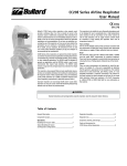
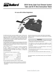
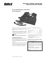
Dual-Cool™ Climate Control Tube
and DC65 Vest User Manual
TM
For use with PC90 Series Containment
Airline Respirators
Includes: DC60 Series Dual-Cool tube, cooling vest connector
hose, reinforcing rings, belt bracket, and belt. Note: The DC65
cooling vest and respirator breathing tube must be ordered
separately.
The requirements for Grade D breathable air include:
Function: The DC60 Dual-Cool tube is NIOSH approved to supply a
continuous flow of cool air to Bullard PC90 Series supplied-air
containment respirators. All Bullard parts must be present and
properly assembled to constitute a NIOSH approved respirator.
Carbon monoxide ...................................................... 10 ppm max.
NOTE
The DC60 Dual-Cool tube cannot be used with a low
pressure air source such as an ambient air pump.
No toxic contaminants at levels that make air unsafe to breathe.
Air Quality Requirements
Respirable air must be supplied to the point-of-attachment of the
NIOSH approved Bullard air supply hose, where the air supply
hose connects to the fitting. Always use an inlet filter on your air
source and monitors and alarms as necessary to assure clean,
breathable air.
Supplied breathing air must at least meet or exceed the
requirements for Type 1 gaseous air as described in the
Compressed Gas Association Commodity Specification G-7.1
(Grade D or higher quality) and specified by Federal Law 42 CFR,
Part 84, Subpart J, 84.141(b) and 29 CFR 1910.134(i)(1)(ii).
Oxygen ......................................................................... 19.5-23.5%
Hydrocarbons in mg/m3 of gas .............................. 5 mg/m3 max.
Carbon dioxide ..................................................... 1,000 ppm max.
Odor ............................................................ No pronounced odor*
* Specific measurement of odor in gaseous air is impractical. Air
normally may have a slight odor.
The presence of a pronounced odor should render
the air unsatisfactory.
Contact the Compressed Gas Association (1235 Jefferson David
Highway, Arlington, VA 22202 or www.cganet.com) for complete
details on Commodity Specification G-7.1.
WARNING
Before using this product, read and follow all directions and
warnings, including those in the respirator instruction manual.
The respirator’s air source must supply clean, breathable air,
Grade D or better, at all times. The respirator does not purify air
or filter out contaminants.
Connecting the respirator to a line supplying nitrogen or other
harmful gases could cause death or serious injury.
Failure to follow these instructions could result in death or
serious injury.
www.bullard.com
TM
Air Pressure
Air Supply Hose
Breathing air pressure must be continually monitored at the pointof-attachment while operating the respirator. A reliable air
pressure gauge must be present to monitor the pressure during
respirator operation.
To maintain your Bullard respirator’s NIOSH approval, use only
approved Bullard V10 Series hose(s) in lengths of 50 to 300 feet,
or Bullard V5 Series hose in lengths of 25 to 50 feet. Bullard V11
hose-to-hose adapters MUST be used to connect V10 hose lengths
together. Secure connection(s) until wrench tight and leak free.
WARNING
NOTE
Do not use a quick-disconnect fitting to connect a V10
hose to the air source. This would restrict airflow and
is not approved in this configuration.
Failure to supply the minimum required pressure at the point-ofattachment for your hose length and type will reduce airflow
and could result in death or serious injury.
Make certain that your breathing air compressor has
sufficient capacity to deliver a minimum of 30 cfm per
respirator wearer at all times. Because Dual-Cool has
two cool tubes, it requires a higher than normal volume
of air.
The Breathing Air Pressure Table on the next page defines the air
pressure ranges necessary to provide the PC90 Series respirators
with a volume of air that falls within the required range of 6-15
cubic feet per minute (cfm) or 170-425 liters per minute (lpm). (See
42 CFR, Part 84, Subpart J, 84.150). To use the table, follow the
steps identified below:
1. Confirm the air source, respirator model, breathing tube, and
Dual-Cool tube assembly (Columns 1-4).
2. Confirm your choice of NIOSH approved Bullard air supply
hose(s) (Column 5).
3. Determine that your air supply hose does not exceed the
maximum approved hose length (Column 6) or number of hose
sections (Column 7).
4. Set the air pressure at the point-of-attachment within the
required pressure range (Column 8) for your air supply hose
length.
WARNING
Use of any other air supply hose voids NIOSH approval of the
entire respirator assembly and might reduce the airflow to the
respirator, which could result in death or serious injury to the
respirator wearer.
Compressed air must be dry enough to prevent ice buildup in the cold
airstream. Ice could reduce airflow into the respirator hood.
WARNING
The DC60 Dual-Cool climate control system is not recommended
for cooling the air supply when the air temperature is less than
70° F. Because the DC60 Dual-Cool may cool the incoming air by
more than 30° F, it is possible for ice to form in the breathing
tube and reduce the airflow. Failure to observe these warnings
could result in death or serious injury.
Replacement Parts
CATALOG
NUMBER
DESCRIPTION
DC65ML
Medium/Large Cooling Vest
DC65XLXXL
X-Large/XX-Large Cooling Vest
CH60
DC50 Series Dual-Cool Connector Hose
4612
Nylon Belt
Breathing Air Pressure Table
This table defines the air pressure ranges necessary to provide the PC90 respirator with a volume of Grade D breathable air that falls within the U.S. Government
required range of 6-15 cfm (or 170-425 lpm). See 42 CFR, Part 84, Subpart J, 84.150.
(1)
Air Source
Stationary
(2)
(3)
Respirator
Breathing
Tube
PC90
90BT
or portable
compressor
90BTF
(4)
(5)
(6)
(7)
(8)
Air Supply
Hose
Maximum Air
Supply Hose
Length
(feet)
Maximum
Number
of Hose
Sections
Required
Pressure
Range
(psig air)
DC6040 1/4" Ind. Int., steel
50
2
48-52
DC604B 1/4" Ind. Int., brass
100
3
59-63
150
3
68-72
Dual-Cool
Tube Assembly
DC6040S 1/4" Ind. Int., stainless
V10
supplying
DC6041 1/4" Schrader
200
3
80-84
DC6042 1/4" Snap-Tite, steel
250
3
85-92
breathing
DC6043 1/4" Snap-Tite, brass
300
5
90-98
air
DC6044 1/4" Snap-Tite, stainless
25
1
53-57
50
2
67-71
Grade D
90ELF
V5
DC6047 1/4" Cejn, steel
Dual-Cool™ Climate Control Tube
and DC70 Vest Instructions
Assembly and Use
2. Install the small nylon clamp over the air entry sleeve and cooling vest connector
hose. Engage the clamp locks and squeeze until tight (Figure 3).
Assembly must be conducted in an uncontaminated atmosphere.
Preparing the CS90 Containment Suit for the
Dual-Cool Tube
1. Place the CS90 containment suit on a flat surface with front side up. Measure
approximately 23" down from the top of the shoulder seam and 1" in front of the
suit’s right side seam. Mark this location with a pen (Figure 1).
To remove
To tighten
To tighten
Figure 3
Assembling the DC60 Dual-Cool Tube
1. Remove the nylon clamp from the open end of the respirator’s breathing tube.
Insert the breathing tube 5 inches into the PC90 respirator parka’s breathing tube
sleeve.(Figure 4).
Figure 1
NOTE
These measurements are only a guideline. Adjust for individual fit.
2. Peel the paper from one adhesive-backed reinforcing ring and apply the ring to the
suit with your location mark in the center of the ring. Use small, sharp scissors to
cut out the suit material in the center of the ring.
3. Add a second reinforcing ring to the underside of the garment, directly beneath the
first ring.
Figure 4
NOTE
Do not remove foam from inside breathing tube. The foam helps reduce
the noise level of incoming air.
2. Install the large nylon clamp over the breathing tube sleeve and breathing tube,
inserting the clamp locks through the two holes in the plastic anchorplate. Locks
should face away from the user’s neck. Engage the clamp locks and squeeze until
tight (Figure 3).
3. Lace the belt through the slots in the belt bracket (Figure 5).
Assembling the DC65 Cooling Vest
1. Insert the muffler end of the cooling vest connector hose well into the air entry
sleeve of the vest (Figure 2).
4. Place left hand around the belt bracket, and right hand around the Dual-Cool tube.
Squeeze the quick-disconnect lever with your right thumb and pull the bracket and
shaft away with your left hand (Figure 5).
5. Unscrew and remove the plastic ring nut from the shaft (Figure 5).
6. Screw the breathing tube onto the threaded connector on the Dual-Cool (Figure 5).
Vest “V” or notch
Figure 2
TM
Head
Protection
Respiratory
Protection
Fire and Rescue
Safety
Thermal
Imaging
Donning the Dual-Cool Tube
and Cooling Vest
1. Don the belt, belt bracket, and Dual-Cool. Adjust belt
comfortably, but loosely, around your waist.
2. Don the vest. Use the hook and loop closure strips to adjust
loosely for size.
NOTE
The vest should mount over the belt with the DualCool unit positioned in the "V" of the vest found on the
right-hand side (Figure 2).
3. Snap the quick-disconnect nipple found on the end of the
cooling vest connector hose into the quick-disconnect coupler
on the Dual-Cool (Figure 5).
Air supply hose
Figure 6
8. Adjust the air pressure at the point-of-attachment to within
the approved pressure range (Figure 7). See the Air Pressure
section on the previous page.
Pressure gauge
Point-ofattachment
Grade “D”
breathable air
source
Quick-disconnect
nipple
Quick-disconnect
nipple
9. Don the PC90 parka by following the directions in your PC90
instruction manual.
Left-hand
temperature
control knob-for
Dual-Cool vest
Belt
Figure 5
4. Don the CS90 by following the directions in your PC90
instruction manual. If you do not have instructions, contact
Bullard Sales Support at the address or phone number given
below, or visit the Bullard website, www.bullard.com.
5. With the approved Bullard air supply hose connected to the
breathing air source, and with air flowing into the hose, connect
the quick-disconnect coupler on the air supply hose to the
quick-disconnect nipple on the Dual-Cool (Figure 6).
6. Slide the shaft that is attached to the belt bracket through the
reinforced opening in the suit (Figure 6).
7. Thread the plastic ring nut onto the shaft (Figure 6). Tighten
firmly against the suit.
Bullard
1898 Safety Way
Cynthiana, KY 41031-9303
Toll free: 877-BULLARD (285-5273)
Tel: 859-234-6616
Fax: 859-234-8987
www.bullard.com
Bullard GmbH
Hochkreuzallee 36
53175 Bonn-Bad Godesberg
Germany
Tel: +49 228 931933 0
Fax: +49 228 931933 50
10. While squeezing the quick-disconnect lever, reconnect the
Dual-Cool tube to the shaft on the outside of the suit, pressing
firmly until it locks in position (Figure 6).
Operating the Dual-Cool Tube
1. To obtain cooler air, turn the air temperature control knobs
counterclockwise (Figure 5). Maximum cooling is obtained
when knobs are open completely and when there is
maximum airflow out of the Dual-Cool tube’s exhaust ports.
To obtain air that is closer to ambient temperature, turn air
temperature control knobs clockwise. If knobs are closed
completely, your respirator will receive air that is essentially
at ambient temperature.
NOTE
There are separate controls to adjust the
temperature of the air that is distributed to the vest
and the breathing zone. The right-hand knob controls
the air temperature to the respirator; the left-hand
knob controls the air temperature to the cooling vest
(Figure 5).
2. When finished working, leave the work area wearing the
respirator. With the air still flowing, remove the hood, and then
disconnect the air supply hose using the quick-disconnect
coupler attached to the Dual-Cool.
IS O
Threaded
connector
Left-hand
temperature
control knob-for
respirator
9 0 01
ed
Cooling vest
Connector hose
ifi
Quick-disconnect
nipple
Breathing tube
Figure 7
Air supply hose
Ce
rt
ISO 9001
certified
©2001 Bullard. All rights reserved, including the right of reproduction,
in whole or in part, in any form.
“It’s your life and you’re worth it,” and Dual-Cool are
trademarks of Bullard.
6088000325(0901)