1
Aerosol Photometer
Aerosol Photometer
2i
Operation and Maintenance Manual
P/N. 1800224, Revision E
May 2015
Aerosol Photometer
(This Page Intentionally Left Blank)
Aerosol Photometer - 2i
2
Aerosol Photometer
Content
Chapters
CHAPTER 1
CHAPTER 2
CHAPTER 3
CHAPTER 4
Introduction and Precautions
Scope of Manual
Definitions
Definiciones
Définitions
Definitioner
定义
User Responsibility
Precautions
For Customers in Canada
For Customers in the USA
For Customers in Europe
For All Customers
Photometer Overview
Instrument Description
Filter Leak Testing: The Most Common Application
How the Photometer Operates
Theory of Operation
Sampling System
Light Scattering Chamber (LSC)
Capabilities
Input / Output features
Utility Requirements
Unpacking and Setting Up the Photometer
Packing List
Unpacking
Installation
Before you begin
Connecting Electrical Power
Connecting the Scanning Probe
Connecting the Interface Ports
USB Port
Printer Port
Know Your Equipment
Front Panel General Overview
Rear Panel General Overview
Scanning Probe Overview
Thermal Printer Overview
Function Keys
Aerosol Photometer - 2i
7
7
7
8
8
9
9
10
10
12
12
14
15
16
16
16
18
18
18
18
19
19
19
21
21
21
21
22
22
23
24
24
24
26
26
27
28
29
30
3
Aerosol Photometer
CHAPTER 5
CHAPTER 6
CHAPTER 7
CHAPTER 8
Sampling Ports
Operating the 2i: Basic Operation
Before You Begin
Basic Operation
Reporting Modes
Summary Mode
Monitoring
Continuous
Alarms Modes and Set Point
Alarm Set Point
Alarm modes
Icons
Software Reference
Software Description
Start-up Screen
Making Entries
Entering Numerical Values
Turning Options Flags On or Off
Using the Alphanumerical Keypad
General Screen Structure
Menu Structure and Options
Menu Structure
Run Mode Screen
Top Level Menu Options
Alarm Set Point
Alarms
Set 100% to Upstream Concentration
Instructions
Measuring the Upstream Aerosol
Accepting the Result
Set Internal Reference
Use Previous 100% Settings
Re-establish Zero
Setup
Aerosol Noise Suppression
Reporting Functions
Date and Time
Display
Error Messages
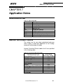
Application Notes
Abbreviations List
Aerosol Correction Factors
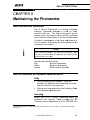
Maintaining the Photometer
Definitions and Features
Recommended Scheduled Maintenance
Daily
Aerosol Photometer - 2i
30
31
31
32
34
34
37
38
39
39
39
40
41
41
41
42
42
43
43
44
45
45
46
47
48
49
49
50
50
51
51
52
52
53
53
55
56
57
59
60
60
60
61
61
61
61
4
Aerosol Photometer
CHAPTER 9
APPENDIX A
APPENDIX B
APPENDIX C
APPENDIX D
APPENDIX E
APPENDIX F
APPENDIX G
APPENDIX H
APPENDIX I
APPENDIX J
APPENDIX K
Annually
Replacing the Main Power Fuses
Cleaning the Lint Screens
Troubleshooting Guide
Instrument Will Not Power Up
Error E1 – Sample Line Blockage
Error E2 – Out of Temperature Range
Error E3 – Photomultiplier Tube (PMT) Inoperable
Contacting ATI
For Technical Support or Application Questions
For Customer Service
Warranty
Declaration of Conformity
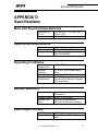
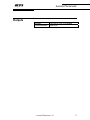
Specifications
Main Unit Physical Characteristics
Operational Requirements
Operating Conditions
Aerosol Detection
Data Output Formats
Outputs
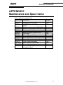
Maintenance and Spare Items
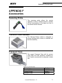
Accessories
Scanning Probe
Thermal Printer Module
Transport Case
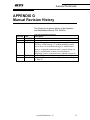
Manual Revision History
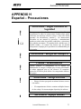
Español – Precauciones
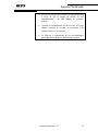
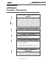
Français – Précautions
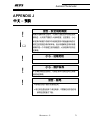
中文 – 预防
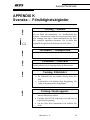
Svenska – Försiktighetsåtgärder
61
62
62
64
64
64
65
65
66
66
66
67
69
70
70
70
70
70
70
71
72
73
73
73
73
74
75
77
79
81
Figures
Figure 1: Front Panel Overview
Figure 2: Rear Panel Overview
Figure 3: Scanning Probe Overview
Figure 4: Thermal Printer Overview
Figure 5: Basic Operation of the 2i Aerosol Photometer
Figure 6: Sample Summary Mode Reporting Ticket
Figure 7: Sample Monitoring Mode Data Output
Figure 8: Start-up Screen
Figure 9: Alphanumeric Keypad
Figure 10: Screen Structure
Figure 11: Overview of the 2i Menu Structure
Aerosol Photometer - 2i
26
27
28
29
32
37
38
42
44
44
45
5
Aerosol Photometer
Figure 12: Running Mode Screenshot
Figure 13: Main Menu Screenshot
Figure 14: Setting the Alarm Set Point Screenshot
Figure 15: Setting the Alarms Screenshot
Figure 16: Set 100% to Upstream Concentration Initial Screenshot
Figure 17: Set 100% to Upstream Concentration Measurement Screenshot
Figure 18: Set 100% to Upstream Concentration Final Screenshot
Figure 19: Set Internal Reference Screenshot
Figure 20: Setup Menu Screenshot
Figure 21: Aerosol Noise Suppression Screenshot without Probe
Figure 22: Aerosol Noise Suppression Screenshot with Probe
Figure 23: Reporting Functions Screenshot
Figure 24: Date and Time Menu Screenshot
Figure 25: Set Time Screenshot
Figure 26: Set Date Screenshot
Figure 27: Set Date Format Screenshot
Figure 28: Display Setup Screenshot
Figure 29: Display Setup Screenshot
Figure 30: Error Message Screenshot
46
47
48
49
50
50
51
51
53
54
54
55
56
56
56
57
57
58
59
Tables
Table 1: Serial Port Settings ............................................................................................. 24
Table 2: Summary Reporting Mode Ticket ...................................................................... 36
Table 3: Monitoring Reporting Mode Ticket.................................................................... 37
Table 4: Icons Description ................................................................................................ 40
Table 5: Running Mode Options....................................................................................... 46
Table 6: Main Menu Options ............................................................................................ 47
Table 7: Alarm Set Point Options List.............................................................................. 48
Table 8: Alarm Selection Options List ............................................................................. 49
Table 9: Internal Reference Set Point ............................................................................... 51
Table 10: Noise Suppression Options List........................................................................ 54
Table 11: Reporting Mode Options List ........................................................................... 55
Table 12: Date and Time Menu Options List ................................................................... 58
Table 13: Date and Time Menu Options List ................................................................... 58
Table 14: List of Operator Error Messages....................................................................... 59
Table 15: Abbreviations List ............................................................................................ 60
Table 16: Aerosol Correction Factors List........................................................................ 60
Table 17: Replacement Fuses for the 2i ............................................................................ 62
Table 18: Maintenance and Spare Items ........................................................................... 72
Table 19: Accessories List ................................................................................................ 73
Table 20: Manual Revision History .................................................................................. 74
Aerosol Photometer - 2i
6
Aerosol Ph
hotomete
er
CH
HAPTER 1
Inttroduction and Preca
aution
ns
Sco
ope of Manual
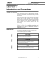
These ins
structions ccover the sspecification
ns, featuress,
operation,, maintenan
nce, and tro
oubleshootiing for the 2
2i
Photomete
er.
These ins
structions a
also contain
n importantt informatio
on
required for
f
the sa
afe operatio
on of the instrumen
nt.
Before using this insstrument, alll personne
el associate
ed
d and unde
erstand thiis
with the operation must read
m
and become
e familiarr with th
he
entire manual
terminolog
gy.
o follow the specified proce
edures an
nd
Failure to
precaution
ns could re
esult in PE
ERSONAL INJURY o
or
DAMAGE
E to the unitt.
Deffinition
ns
The follow
wing definess the warnin
ngs, cautions and
notes used througho ut this man
nual.
!
!
i
Warnin
ng
Indicates a strong posssibility of seevere personnal injury or
nstructions ar
are not follow
wed.
death if in
Caution
n
Indicates a possibilityy of equipmeent damage if
instruction
ns are not foollowed.
Note
Indicates that
t helpful informationn is providedd.
Aerosol Photometerr - 2i
7
Aerosol Photometer
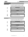
Definiciones
Las siguientes anotaciones definen los peligros,
cuidados y notas usadas a lo largo de este manual.
!
!
i
Advertencia
Indica una fuerte probabilidad de serias lesiones
personales o muerte si no son seguidas las instrucciones.
Cautela
Indica una posibilidad de daños al equipo si no son
seguidas las instrucciones.
Nota
Indica que se suministra información útil.
Définitions
Les informations suivantes, définissent les symboles,
précautions et notes présentes dans ce manuel.
!
!
i
Avertissement
Indique la possibilité de dommages corporels graves
pouvant entraîner la mort, si les instructions ne sont pas
suivies.
Attention
Indique la possibilité d’endommager l’équipement si les
instructions ne sont pas suivies.
Note
Indique que des informations utiles sont fournies.
Aerosol Photometer - 2i
8
Aerosol Photometer
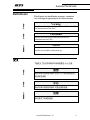
Definitioner
Efterföljande text beträffande varningar, varsamhet
och noteringar är genomgånde för hela manualen.
!
!
i
Varning
Innebär att allvarlig personlig skada eller död kan inträffa
om instruktionerna inte följs.
Varsamhet
Innebär att skador på utrustning kan inträffa om
instruktionerna inte följs.
Notera
Innebär att användbar information ges.
定义
下面定义了在这本说明书中所有的警告,小心,注意.
!
!
i
警告
表示如果不按照指导操作.引起个人人身伤害甚至死亡
的可能性很高.
小心
表示如果不按照指导操作.可能会损害仪器
注意
表示提供了有用的信息.
Aerosol Photometer - 2i
9
Aerosol Photometer
User Responsibility
The user must:
1. read and comprehend the information contained in
this manual before using the product;
2. have an understanding of the electrical and
mechanical system principles used in the
operation of this photometer;
3. be trained in the proper use of electro-mechanical
equipment;
4. properly use this product for the intended purpose
and follow all regulations and procedures that
apply to the location where this product is used;
5. maintain the product as specified in this manual;
6. maintain and keep in proper working condition any
other equipment associated with the operation of
this product.
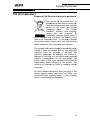
Precautions
Warning – General Safety Rules
!
i
Read and understand all instructions. Failure to follow all
instructions listed below may result in electric shock, fire
or serious personal injury. The warnings, cautions, and
instructions discussed in this operation and maintenance
manual cannot cover all possible conditions and situations
that may occur. It must be understood by the operator that
common sense and caution are a factor which cannot be
built into this equipment, but must be supplied by the
operator.
Caution – Shipping Hazard
!
!
When returning a 2i-N for service, the end user must
remove the potentially contaminated sampling train prior
to shipping the instrument. Refer to the 2i-N addendum for
the proper procedure.
Caution –Serviceability
There are no user-serviceable parts inside the instrument.
Refer all repair and maintenance to a qualified factoryauthorized technician.
Aerosol Photometer - 2i
10
Aerosol Photometer
!
!
Caution - Maintenance
Incorrect fuse replacement
components of the photometer.
may
damage
internal
Warning – Electrical Hazard
Electrical hazard that can cause severe injury or death.
The electrical housing contains multiple high voltage
sources. Do not insert any objects under the cover
!
Warning – Damaged Equipment
Do not operate the equipment with a damaged cord or
plug or after the equipment has malfunctioned, or
been damaged in any way.
Contact ATI Service Department for advice on
examination, repair, electrical or mechanical
adjustment.
Failure to follow the prescribed procedures may result
in a hazardous situation.
Aerosol Photometer - 2i
11
Aerosol Photometer
For Customers in Canada
Note – Regulatory Information
i
This Class B digital apparatus complies with Canadian
ICES-003.
Cet appareil numérique de la Classe B est conforme à la
norme NMB-003 du Canada.
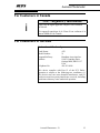
For Customers in the USA
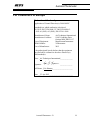
Declaration of Conformity
Trade Name:
Model Number:
Responsible Party:
Address:
Telephone No:
ATI
2i
Hamilton Associates Inc.
11403 Cronridge Drive
Owings Mills, MD 21117
USA
410-363-9696
This device complies with Part 15 of the FCC Rules.
Operation is subject to the following two conditions: (1)
This device may not cause harmful interference, and (2)
this device must accept any interference received, including
interference that may cause undesired operation.
Aerosol Photometer - 2i
12
Aerosol Photometer
Note – Regulatory Information
i
This equipment has been tested and found to comply with
the limits for a Class A digital device, pursuant to Part 15
of the FCC Rules. These limits are designed to provide
reasonable protection against harmful interference in a
residential installation. This equipment generates, uses and
can radiate radio frequency energy and, if not installed in
accordance with the instructions, may cause harmful
interference to radio communications. However, there is
no guarantee that interference will not occur in a particular
installation. If this equipment does cause interference to
radio or television reception, which can be determined by
turning the equipment off and on, the user is encouraged to
try to correct the interference by one or more of the
following measures:
Reorient or relocate the receiving antenna
Increase the separation between the equipment and
receiver
Connect the equipment into an outlet on a circuit
different from that to which the receiver is connected
Consult the dealer or an experienced radio/TV
technician for help
Aerosol Photometer - 2i
13
Aerosol Photometer
For Customers in Europe
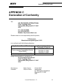
Declaration of Conformity
Application of Council Directive(s): 2004/108/EC
Standard(s) to which conformity is declared:
EN 55011:2007; EN61000-3-2: 2005; EN61000-33:1995:A1 (2001):A2 (2005); EN 61326-1:2006
Manufacturer's Name:
Manufacturer's Address:
Type of Equipment:
Model Number:
Year of Manufacture:
Air Techniques International
11403 Cronridge Drive
Owings Mills, MD 21117
Measurement Instrument
2i Photometer
2012
I, the undersigned, hereby declare that the equipment
specified above conforms to the above Directive(s)
and Standard(s).
Place: _Air Techniques International______________
Signature:
_______________
Full Name: _Eric Hanson_______________________
Date: __23 Apr 2012___________________________
Aerosol Photometer - 2i
14
Aerosol Ph
hotomete
er
Forr All Cu
ustomers
Disposal of Old Electrical & E
Electronic E
Equipmentt
n the produ
uct and / o
or
This symbol on
accom
mpanying d
documents means tha
at
used electrical a
and electronic productts
should not be mixed w
with genera
al
house
ehold wa
aste.
F
For prope
er
treatm
ment, reco
overy and
d recycling
g,
pleasse take this pro
oduct(s) tto
desig nated colle
ection poin
nts where it
will be ac
ccepted free
e of charge
e. This sym
mbol is onlly
valid in th
he Europea
an Union. If you wish
h to discarrd
this produ
uct please contact yo
our local authorities o
or
dealer and
d ask for the correct m
method of disposal.
uct shall no
ot be treate
ed as house
ehold waste
e.
This produ
Instead itt shall be handed o
over to the
e applicablle
collection point fo
or recyclin
ng of ele
ectrical an
nd
electronic equipmen
nt. By enssuring this product iis
disposed of correctlyy, you will help preve
ent potentia
al
nces for tthe enviro
onment an
nd
negative consequen
human he
ealth, which
h could oth
herwise be
e caused b
by
inappropriiate waste
e handling of this product. Th
he
recycling of materia
als will help to conse
erve natura
al
resources
s.
For more detailed in
nformation about recyycling of thiis
product, please
p
conttact your lo
ocal Civic Office, you
ur
household
d waste disposal serrvice or the Compan
ny
where you
u purchased
d this equip
pment.
Aerosol Photometerr - 2i
115
Aerosol Ph
hotomete
er
CH
HAPTER 2
Ph
hotom
meter Overv
view
Ins
strumen
nt Desc
cription
The 2i is
s a forwa rd light-sccattering, liinear digita
al
photomete
er. It opera
ates on 100
0 to 240 Vo
olts, 50 or 6
60
Hz, adjustting automa
atically. Itss most basic function iis
to sample
e air or ot her gases and reporrt the masss
concentra
ation of pa
articulates in the sam
mple. Th
he
primary ap
pplication fo
or the 2i is integrity/lea
ak testing o
of
HEPA/ULPA filtration
n systems.
weight instru
ument. Th
he
The 2i is a compact and lightw
instrument case is constructe
ed of rugge
ed die casst
aluminum. The presssure-sensittive keypad
d and large
e,
ators proviide ease o
of
bright LCD display and indica
eoperation and reada bility. The auto-ranging and one
oing featurres assure
e the accu
uracy of a
all
step zero
readings.
mely intuitivve through the use of a
Using the 2i is extrem
basic men
nu structure
e. Operatio
on of the in
nstrument iis
simple and straigh
ht forward..
Use o
of the fullly
e iProbe a
affords full unit contrrol from th
he
compatible
scanning probe. The
e 2i provide
es easy acccess to rea
altime resu
ults via U
USB or o
optional prrinter, whille
remaining versatile e
enough to accommod
date specia
al
eeds that have beco
ome comm
monplace iin
testing ne
today’s filtter testing industry.
elements ccome togetther as the
ey
When all of these e
have in th
he 2i, the testing pro
ocess ceasses to be a
training in
ntensive exxercise and
d becomess a “set an
nd
forget” se
econdary ro
outine perfformed as part of th
he
daily work
k requireme
ents in clean
n room testting.
Filtter Leak
k Testin
ng: The
e Most Common
Applicatio
on
The mos
st commo
on application of th
he Aeroso
ol
Photomete
er 2i is to
o detect le
eaks in hig
gh efficienccy
filtration systems
s
(H
HEPA & UL
LPA). To validate th
he
integrity of
o a filtratiion system
m, a known challeng
ge
Aerosol Photometerr - 2i
116
Aerosol Photometer
agent consisting of an airborne test aerosol is
generated and introduced upstream of the filter. The
challenge agent provides particulate matter upstream
of the filter to allow measurements downstream of the
filter.
The test aerosol is introduced into the upstream side
of the filter(s) as far from the filters as is practical to
insure adequate mixing. Ideally, a distance of 10 duct
diameters upstream is considered the minimum. A
sample of the aerosol-air mixture should be taken
from the upstream side, close to the center of the
filter/filter bank. This sample is used to establish a
100% base line for the upstream concentration. The
2i is adjusted as described in the Operating Section to
set the 100% reading and the stray light is adjusted
automatically.
The stray light adjustment
compensates for light reflection off internal surfaces of
the scattering chamber. After these adjustments have
been made, the 2i instrument is ready to check for
filter leaks/integrity downstream.
The filter test is performed with the use of the
scanning probe. The filter and the perimeter of the
filter pack should be scanned by passing the probe in
slightly overlapping strokes so the entire area of the
filter is sampled. The end of the probe should be held
one inch from the filter surface. Separate passes
should be made around the entire periphery of the
filter, along the bond between the filter pack and the
frame, and around the seal of the filter. Readings on
the meter will indicate percent of penetration.
The display indicates the percent of leakage through
or around the filter. The iProbe is supplied with the
industry standard rectangular, blue isokinetic nozzle.
This nozzle is used for fast scanning and is accepted
by many standards, including NSF 49-2002.
Other optional probes are available, a round, black 1
inch (25 mm) in diameter nozzle, which complies with
NSF (National Sanitation Foundation) Standard 491992, and a round, red nozzle. The isokinetic nozzles
are designed for face velocities of 90 +/- 20 feet per
minute (fpm) when using a 1 cfm (28.3 L/min) sample
rate.
Aerosol Photometer - 2i
17
Aerosol Photometer
How the Photometer Operates
Theory of Operation
When air or gas is drawn through the instrument,
particulate matter in the sample passes through the
focal point of the scattering chamber. Particulate
matter scatters light into the dark cone and onto the
photomultiplier tube, which converts the light into an
electrical signal. The signal is amplified and digitized,
then analyzed by a microprocessor to determine the
intensity of the light scattered by the signal. This
signal is then compared to a reference signal to
provide an output that is normalized by the reference
signal.
A photometer is ideally suited to detect particulate
matter in air or gas, reporting the mass concentrations
encountered on a display. Particles from less than
0.1 micron to approximately 600 microns can be
detected by the 2i. Since the photometer reports
concentration of particulate matter, many applications
are possible. By using a baseline of 100 micrograms
per liter of aerosol, it is possible to directly read the
concentrations of aerosols.
Sampling System
A vacuum pump in conjunction with a flow meter,
onboard sensors and closed feedback loop provides a
constant volumetric sample flow rate of 1 cfm (28.3
liters per minute). The 2i uses an oil-free, dual head,
diaphragm pump with a direct-coupled DC motor.
Solenoid actuated valving directs the airflow through
the sampling system to the scattering chamber from
three possible sources. The CLEAR position directs
clean air from an internal ULPA filter to the scattering
chamber for zeroing the instrument.
The
UPSTREAM position permits sampling of the air
above the filter being challenged, and the
DOWNSTREAM position permits sampling of the air
that penetrates the filter.
Light Scattering Chamber (LSC)
The scattering chamber is not only an integral part of
the sampling system; it is a major component in itself.
Aerosol Photometer - 2i
18
Aerosol Photometer
The scattering chamber is a complex electro-optical
unit that consists of a pair of hollow cones connected
at the apexes. A pair of collimating lenses first
straightens the light emerging from the light source,
and then focuses it at the center of the sampling
cone. An aperture forms a dark cone around the
photomultiplier, preventing light from arriving directly
on the photomultiplier. A condensing lens opposite
the LED source focuses light scattered into this dark
cone onto the photomultiplier tube.
Capabilities
The Aerosol Photometer 2i will measure percentage
leakage or absolute aerosol concentration.
i
Note
Before attempting to operate this unit, become familiar
with the features and functions.
Input / Output features
Alarms:
The 2i, when used in conjunction with the iProbe,
provides the user three sensory alarms: audible,
visual, and vibratory. When a reading exceeds the
user selected alarm point the display will turn red, a
tone will sound, and the iProbe will vibrate, if enabled.
Data Output:
Leakage data is sent out the unit’s USB port. This
data can be logged with contemporary data
acquisition software in real-time. Multiple types of
data formatting are available to satisfy a wide range of
applications (see “Reporting Modes” page 34 for more
details). Data can also be printed to hard copy using
the optional printer accessory when using the
summary mode.
Utility Requirements
Power
Aerosol Photometer - 2i
19
Aerosol Photometer
The 2i is equipped with a “Universal AC” power
supply capable of handling 100 to 240 VAC, 50 to 60
Hz. A line power conditioner and surge protector is
recommended.
Ambient Air Conditions
While the instrument was design to be operated
through a wide range of environmental condition, we
recommend its use in a controlled environment where
the temperature is between 1°C and 45°C (34°F to
120°F Fahrenheit) and the relative humidity is
between 20% and 95% non-condensing.
i
Note
A dedicated power line is recommended for stable
machine operation.
Aerosol Photometer - 2i
20
Aerosol Ph
hotomete
er
CH
HAPTER 3
Un
npack
king and
a Se
etting
g Up tthe
Ph
hotom
meter
Pac
cking List
L
The 2i sh
hips comple
ete, ready to install a
and operate
e.
Any addittional acce
essories pu
urchased on the sam
me
order will be listed as separa
ate line ite
ems on th
he
shipment packing lisst. Please
e confirm re
eceipt of a
all
mmissionin
ng of the insstrument.
line items prior to com
he following
g.
Shipping with the sstandard 2i will be th
ay be pacckaged se
eparately o
or
Individual items ma
installed:
urdy Pelican
n Shipping instrument case
Stu
“Op
peration an d Maintena
ance” Manu
ual
Callibration Re
eport
iPro
robe Scanning Probe w
with umbiliccal
12 feet of clea
ar sampling
g tube
One set of spa
are o-rings and lint scrreen
Pow
wer Cord (N
NEMA 5-15
5 125V or C
CEE 7/4
“Sc
chuko” 250V
V configura
ation)
NSF 49:2002 Isokinetic rrectangularr nozzle
Unpacking
Whereverr possible, packing materials should b
be
retained for stora
age or fu
uture ship
pment an
nd
transporta
ation needs .
After unpa
acking, if a
anything is missing orr appears tto
be dama
aged, con
ntact ATII Customer Servicce
immediate
ely at (410)) 363-9696
6 (see “Con
ntacting AT
TI”
page 66).
Ins
stallatio
on
!
Warnin
ng
Aerosol Photometerr - 2i
221
Aerosol Photometer
If the unit is used in a manner not specified within the
user’s manual, the protection offered by the equipment
may be impaired.
Before you begin
You will need the following items to set up the Aerosol
Photometer Model 2i
i
Electrical outlet (110 VAC or 220 VAC)
2i Scanning Probe or PVC Sampling Tube
1°C to 45°C ambient temperature
Less than 95% RH, non-condensing.
Note
High ambient temperatures may create instability in the
readings.
Connecting Electrical Power
Voltage and current requirements for the Aerosol
Photometer Model 2i are:
100 to 240 VAC, 2 amps
The Aerosol Photometer automatically adjusts to
operate at the correct AC voltage for the destination
country (given this voltage is within the specifications
described in “APPENDIX D Specifications page 70).
This voltage is noted on a label attached to the back
panel of the instrument. The power cord contains a
plug which is specifically adapted to the destination
country.
You are responsible for plugging the power cord into
a matching receptacle. To connect the Aerosol
Photometer to electrical power, do the following:
1. Check to make sure the Aerosol Photometer is
turned off. (Refer to Figure 2: Rear Panel Overview,
for the location of the power switch.)
Aerosol Photometer - 2i
22
Aerosol Photometer
2. Plug the power cord into a matching power outlet.
Warning
!
Before connecting the power cord to the power outlet,
make sure the cord has not been cut or otherwise damaged
during shipment.
!
To prevent damage to the Aerosol Photometer, make sure
the voltage listed on the back panel matches the power
outlet where you plug it in.
Caution
Connecting the Scanning Probe
If using the Aerosol Photometer 2i with the Scanning
Probe, you should first connect the iProbe to the
umbilical. To do so, connect the umbilical’s electrical
connector to the 7-pin connector on the end of the
probe. Connect the aerosol sampling line quickconnect fitting to the quick-connect connector on the
butt of the probe (see “Scanning Probe Overview”
page 28 for the probe description).
i
Note
The two pneumatic quick-connect fittings are different; the
smaller one must be connected to the iProbe, while the
bigger one must be connected to the 2i base.
Once the umbilical is connected to the scanning
probe, connect the other end to the main unit.
Connect the umbilical’s electrical connector to the 7pin connector on the front panel of the 2i. Connect the
aerosol sampling line quick-connect fitting to the
quick-connect port of the photometer marked
“DOWNSTREAM” (see “Front Panel General
Overview” page 26 for the front panel component
description).
i
Note
Aerosol Photometer - 2i
23
Aerosol Photometer
Always check the lint screen in both sampling ports before
using the instrument (see “Maintaining the Photometer”
page 61 for the procedure).
Note
i
When using the iProbe with the 2i, the probe should be
connected to the photometer before the power is turned on.
Otherwise the iProbe display will show the following
message until the main unit has reached the running mode:
“Waiting for User to complete current Base operation”
Connecting the Interface Ports
The 2i comes equipped with two standard Interface
Ports: a USB port and a printer port.
USB Port
The USB port is intended to interface with a computer
to provide serial data acquisition capability. The port
connection requirements are described in the
following table.
Table 1: Serial Port Settings
Setting
Transfer Speed
Data Bits
Stop Bits
Parity Control
Flow Control
Value
9600
8
1
N
None
Printer Port
A 5-pin mini-din circular connector provides the
interface with the optional thermal printer. The
connector is keyed to prevent connection mistakes.
To connect, orient the arrow toward the top and insert
the connector in the receptacle.
Aerosol Photometer - 2i
24
Aerosol Photometer
i
Note – Port Usage
Do not use the Printer Port with equipment other than
those designed and supplied by ATI. Damage to the
equipment might result from such action
Aerosol Photometer - 2i
25
Aerosol Ph
hotomete
er
CH
HAPTER 4
Kn
now Your
Y
Equip
E pmentt
Fro
ont Pan
nel General Ov
verview
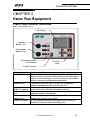
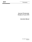
w
Figure 1: Front Pan
nel Overview
LCD Dis
splay
Upstream
m
Sample
S
Port
Downstream
D
m
Sample
S
Portt
Valve Selection with
w
LED Indica
ator
Function
n
Keyss
iPrrobe Conne
ector
Des
scription
LCD
D Display
Fun
nction Keys
Valv
ve Selection
with
h LED Indic
cator
Ups
stream Sam
mple
Port
Dow
wnstream
Sam
mple Port
iPro
obe Connec
ctor
Fun
nction
The
e color LCD
D display is the primary
ry interface with the 2i..
Durring operatiion, percen
nt leakage rreadings are
e displayed
d as
welll as icons informing th
he user of the selection and statu
us of
alarms, selecttions and co
onnected p
peripherals.
The
e function keys
k
are us ed to accesss the settin
ngs and
ope
erating para
ameters witth the menu
u structure.
Pre
essing one of the butto
ons will sele
ect the portt as the sou
urce of
aerrosol and a blue LED w
will indicate
e the selecttion.
Con
nnects to th
he sample ttubing that is used to m
measure th
he
ups
stream aero
osol concen
ntration.
Con
nnects to th
he sample ttubing that is used to m
measure th
he
dow
wnstream aerosol
a
concentration.
A 7-pin
7
circula
ar connecto
or with bayo
onet lock prrovides the
elec
ctrical conn
nection for tthe scannin
ng probe.
Aerosol Photometerr - 2i
226
Aerosol Photometer
Rear Panel General Overview
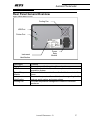
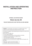
Figure 2: Rear Panel Overview
Cooling Fan
USB Port
Printer Port
Instrument
Identification
Description
Printer Port
USB Port
Power Entry
Module
Instrument
Identification
Cooling Fan
Power
Entry
Module
Function
Connection port for the optional thermal printer.
Connection port to interface with a computer or data
acquisition system.
Connects the instrument to the wall outlet. It also contains the
fuses.
Provides the operator with useful information regarding the 2i,
such as serial number and power ratings.
Provides temperature management inside the instrument
enclosure.
Aerosol Photometer - 2i
27
Aerosol Photometer
Scanning Probe Overview
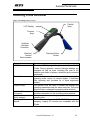
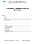
Figure 3: Scanning Probe Overview
Flexible
Hose
LCD Display
Function
Keys
Umbilical
Electrical
Connector
Umbilical
Aerosol
Quick-connect
Description
LCD Screen
Flexible Hose
Function Keys
Umbilical Electrical
Connector
Umbilical Aerosol
Quick-connect
Scanning Probe
Nozzle
Scanning Probe
Nozzle
Function
The color LCD display is the primary interface with the
iProbe. During operation, percent leakage readings are
displayed as well as icons informing the user of the
selection and status of alarms, selections and connected
peripherals.
The flexible hose allows the operator to orient the
scanning probe nozzle at various angles. It facilitates
filter scanning and provides for a more ergonomic
position.
The function keys are used to access the settings and
operating parameters with the menu structure. They also
allow the user to change the sampling valve selection.
A 7-pin circular connector with bayonet lock provides the
electrical connection for the scanning probe umbilical.
Connects to the scanning probe umbilical aerosol
sampling tube.
This nozzle complies with NSF 49:2002 for isokinetic
sampling. Legacy ATI nozzles are compatible with the
iProbe.
Aerosol Photometer - 2i
28
Aerosol Photometer
Thermal Printer Overview
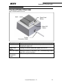
Figure 4: Thermal Printer Overview
Latch
Paper Feed
Button
Blue LED
Status
Printer
Connection Cable
Description
Latch
Function
Pulling on the latch will unlock and open the cover to allow
changing the paper roll.
Pressing this button feeds blank paper from the roll.
Paper Feed
Button
Blue LED Status Indicate the status of the printer. See “Troubleshooting Guide”
page 64 for more information.
Printer
Connects the printer the 2i base unit.
Connection
Cable
Aerosol Photometer - 2i
29
Aerosol Photometer
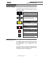
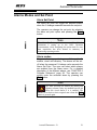
Function Keys
The function keys on the iProbe are identical to those
of the 2i front panel. The iProbe, however, does not
have a power button.
Power Button
To turn the instrument ON and OFF.
Arrow Pad Buttons
To navigate the menus, change
values and validate choices. The
center button is the enter key.
Play / Pause Button
To start the summary or monitoring
reporting functions as well as pause
them.
Stop Button
To stop the summary or monitoring
reporting functions.
Mute Button
To mute the audible and vibratory
alarms.
Keyboard Button
To call the keyboard to the screen
for entering a scanning location.
Sampling Ports
The sampling ports connect the instrument to either
the scanning probe or 12 feet of clear tubing. They
are quick-connect type connectors and are
removable.
Each port contains a lint trap that should be cleaned
periodically to prevent clogging (see “Maintaining the
Photometer” page 61 for the procedure).
Aerosol Photometer - 2i
30
Aerosol Ph
hotomete
er
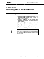
CH
HAPTER 5
Op
peratiing th
he 2i: Basic
c Ope
eration
Beffore Yo
ou Begin
1) Attach the supplie
ed power ccord and co
onnect to a
an
priately rate
ed electrica
al outlet. 110V @ 10
approp
amps or
o 220V @ 5 amps.
2) Check the clea
anliness of the upsstream an
nd
stream port lint traps. T
They should be free o
of
downs
fibers and
a debris..
3) Conne
ect the iP
Probe elecctrical con
nnector an
nd
sampling line to th
he main un
nit if desired
d.
ect the prin ter accesso
ory or data
a acquisitio
on
4) Conne
system
m if desired..
5) Enable
e operation
nal power b
by switching
g the powe
er
entry module
m
to th
he ‘ON’ possition.
i
Note – User M
Manuall
Make surre that the ooperator has been propeerly trained to
use the in
nstrument. A
At a minimuum, he shouuld have reaad
this User Manual.
M
Aerosol Photometerr - 2i
331
Aerosol Photometer
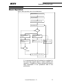
Basic Operation
Figure 5: Basic Operation of the 2i Aerosol Photometer
Step 1 Power On
Step 2 Initialization
Step 3 Establishing Zero Level
Step 4 Main Menu
Step 5 Selecting an
Aerosol
Step 5 Selecting an
Aerosol
Step 6 - a
Set 100% to Upstream
Concentration
Step 6 - b
Set Internal Reference
Step 6 - c
Use Previous 100%
Settings
Exit
Proceed
Step 7 Performing Leak Testing
It is recommended that all routines be completed in
the order they appear above to ensure reliable unit
operation. Completion of these routines will provide a
daily confirmation of the operational state of the
photometer.
Aerosol Photometer - 2i
32
Aerosol Photometer
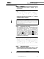
Step 1
Power On
Press the power button located at the lower right of
the front panel.
Step 2
Initialization
When the unit is powered on, it undergoes an
initialization cycle during in which it polls the system
for available sensors and verifies communication with
those sensors. The instrument will also regulate the
sample line flow and once it reaches 28.3 ALPM the
initialization phase is complete.
i
Note
Other information available on the screen is the unit serial
number, software revision, machine identification number
and the total operating hours. See “Software Description”
page 41 for details.
Step 3
Establishing Zero Level
After initializing, the unit will automatically proceed
with establishing the zero level. This process takes
approximately 10 seconds. If it cannot establish a
zero, the operator will be prompted to retry up to three
times. The operator should press the Yes button to
retry or the No button to shutdown the instrument.
The operator will have to press the Ok button to
shutdown the instrument if the zero level cannot be
established at the last attempt.
Step 4
Main Menu
Once the zero level is established, the instrument will
display the main menu. The operator can then choose
to change parameters, such as the reporting function,
date and time, or the alarm settings. He must then
decide the method he wants to use to set the 100%
reference for the instrument.
Step 5
Selecting an Aerosol
Before proceeding with setting up the 100% it is good
practice to verify that the correct reagent is selected.
i
Note
Aerosol Photometer - 2i
33
Aerosol Photometer
The instrument saves the last reagent selected in memory
even after a power cycle.
Step 6
Choosing a Setup Method
a
Set 100% to Upstream Concentration
The instrument will attempt to establish its
reference baseline to the aerosol introduced in
the upstream aerosol port. If it is successful, an
estimate of the aerosol concentration and
stability will be communicated to the user.
b
Set Internal Reference
The instrument will set its reference baseline
and internal gain based upon settings stored
during factory calibration.
c
Use Previous 100% Settings
The instrument will reset its reference and
internal gain setup to the prior settings.
After successfully setting up the 100% reference, the
instrument will automatically display the running mode
screen and set the sampling valve to the downstream
aerosol port.
Step 7
Performing Leak Testing
The unit is now ready to perform leak testing or
aerosol monitoring. To return to the main menu select
the Home Menu key and press the Enter button (see
“CHAPTER 6 Software Reference” page 41 for a full
software description).
Note
i
If there is a concern that the zero baseline may have
drifted, the operator may re-zero the instrument at any
time by accessing the option in the main menu.
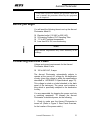
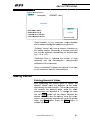
Reporting Modes
Summary Mode
The summary reporting mode was implemented with
certifiers doing in-situ validation of high efficiency
filtration systems (HEPA & ULPA) in mind. It provides
Aerosol Photometer - 2i
34
Aerosol Photometer
a summary of each filter tested on the USB port and,
if connected, on the optional thermal printer. This
feature is similar to that of a particle counter.
When this reporting mode is selected, the
operator has the opportunity to enter a
location for the testing he is about to perform
by pressing the keyboard function key. This field is
automatically reset at the end of the test to avoid
unintended duplication of locations and should be
repopulated prior to subsequent testing.
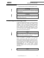
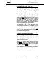
To start the reporting, the operator
should press the play/pause function
key. The header will be sent out to the
ports and the acquisition of data sets will be initiated.
The button LED lights up green and the data transmit
icon is displayed ( ). A data set is sent every time the
operator presses the play/pause function key to
pause the test or at the conclusion of the test. When
the test is paused, the play/pause button LED lights
up yellow and the data transmit icon changes to
indicate the new status ( ). The maximum
penetration value is reset when the operator presses
the play/pause button to resume the test, allowing
the report to show all leaks present during the filter
scan.
i
Note
If the probe is disconnected when the instrument is in play
or pause, it will not synchronize with the base until the
stop button is pressed.
Note
i
If a leak is detected while scanning, the operator should
press the play/pause function key to pause the reporting
and acquisition of data while he fixes the leak. Pressing the
play/pause function key will also stop the effective
scanning time until it is pressed again.
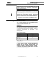
When the operator has concluded the
testing, he must press the stop
function key to end the reporting.
When the key is pressed, the footer is sent out to the
ports and the reporting is terminated.
Aerosol Photometer - 2i
35
Aerosol Photometer
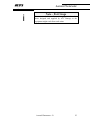
A ticket consists of the following:
Table 2: Summary Reporting Mode Ticket
Header
Photometer Model
Unit Serial #
Calibration Due Date
Date
Field Separator
Location or Filter ID
Setup
Reagent
Actual Concentration
Upstream Value
Scanning Start Time
Field Separator
Data Set
% Leakage Alarm Value
Exceeded Alarm Value
Max % Leakage Value
Field Separator
Footer
End Time
Effective Scanning Time
Text Block
i
Note
If the operator powers off the instrument while a test is in
progress or an error is generated by the instrument, the
message “Test Interrupted” will be sent to the USB and
printer ports.
Aerosol Photometer - 2i
36
Aerosol Photometer
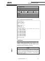
Figure 6: Sample Summary Mode Reporting Ticket
ATI Photometer 2i
Serial #: 123456
Cal Due: 1 May 2013
Date: 1 May 2012
------------------ID: FILTER 123
Setup: Internal Ref
Reagent: PAO
Actual Con.: Upstream Val: 100
Start Time: 12:00
------------------Leakage Alarm: 0.010%
Alarm Exceeded: No
Max Pen.: 0.0004%
------------------Leakage Alarm: 0.010%
Alarm Exceeded: Yes
Max Pen.: 0.0403%
------------------Leakage Alarm: 0.010%
Alarm Exceeded: Yes
Max Pen.: 0.0706%
------------------End Time: 12:19
Scan Time: 3 Min 24 sec
Operator:
Monitoring
The monitoring mode reporting function is similar to
the summary mode reporting function. It differs in the
content and format of the data set and footer. In this
mode the data is only available on the USB port. The
data set is described in the following table.
i
Note
In Monitoring mode, the operator cannot pause the
acquisition of data set.
Table 3: Monitoring Reporting Mode Ticket
Header
Photometer Model
Unit Serial #
Calibration Due Date
Date
Field Separator
Location or Filter ID
Setup
Reference Used
Actual Concentration
Upstream Value
Aerosol Photometer - 2i
37
Aerosol Photometer
% Leakage Alarm
Start Time
Field Separator
Data Set
Leakage
Time
Alarm
Footer
Field Separator
End Time
Field Separator
Alarm
Exceeded
% Leakage
Value
Figure 7: Sample Monitoring Mode Data Output
ATI Photometer 2i
Serial #: 123456
Cal Due: 26 Feb 2013
Date: 29 Feb 2012
------------------ID:
Setup: Internal Ref
Reagent: PAO
Actual Con.: Upstream Val: 100
Start Time: 09:19:00
------------------Timestamp, Leakage Alarm, Alarm Exceeded, Maximum Penetration
4, 0.010%, No,0.0046%
8, 0.010%, No,0.0049%
12, 0.010%, No,0.0053%
16, 0.010%, No,0.0052%
20, 0.010%, No,0.0054%
24, 0.010%, No,0.0053%
28, 0.010%, No,0.0054%
32, 0.010%, No,0.0054%
36, 0.010%, No,0.0053%
40, 0.010%, No,0.0053%
44, 0.010%, No,0.0051%
48, 0.010%, No,0.0052%
------------------End Time: 09:19:48
-------------------
Continuous
The continuous reporting mode will output one %
leakage reading approximately every second to the
USB port of the instrument. The data consists of the
penetration value followed by a comma.
Note
i
The Continuous reporting mode provides a data output
identical to the legacy equipment TDA-2G and TDA-2H.
To use an existing data acquisition system with the 2i
adjust the port settings as described in “Connecting the
Interface Ports” page 24.
Aerosol Photometer - 2i
38
Aerosol Photometer
Alarms Modes and Set Point
Alarm Set Point
The alarm set point will trigger the selected alarms
when the % leakage measured exceeds the set point.
The operator can change the set point by selecting
the alarm set point option and pressing the Enter
button.
Note
i
The Alarm Set Point option is not accessible while the
instrument is setting up to the 100% Upstream
Concentration, while navigating the main menu or once
data acquisition has been started in summary or
monitoring reporting modes.
Alarm modes
There are three types of alarms available on the 2i:
audible, visual and vibratory. The alarms will be setoff when the measured % leakage value exceeds the
Alarm Set Point. The user can select which alarms
are enabled from the Alarm menu. For a detailed
description of the different alarms, see “CHAPTER 6
Software Reference” page 49. The operator can
quickly mute the activated alarm by pressing the
Mute button.
Note
i
The Mute function will disable the audible and
vibratory alarms if they are enabled but will not
affect the visual alarm if it is enabled. The
alarms revert back to their original state when the Mute
button is pressed again.
Aerosol Photometer - 2i
39
Aerosol Photometer
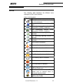
Icons
The following table describes the different icons
displayed on the 2i user interface.
Table 4: Icons Description
Icon
Displayed when …
The optional thermal printer is plug
into the instrument.
A computer is interfaced with the USB
port.
The
Upstream
Aerosol
Noise
Suppression (UANS) is selected.
The Downstream Aerosol Noise
Suppression (DANS) is selected.
The Continuous reporting function is
selected.
The Monitoring reporting function is
selected.
The Summary reporting function is
selected.
The iProbe is connected.
The mute function is enabled.
The Audible alarm is enabled.
The Audible alarm is disabled.
The Vibratory alarm is enabled.
The Vibratory alarm is disabled.
The Visual alarm is enabled.
The Visual alarm is disabled.
The instrument is sending data to the
USB and Printer port.
The data transmission to the USB and
Printer port is paused when in
Summary reporting mode.
Toggle the running mode and the main
menu on the iProbe.
Aerosol Photometer - 2i
40
Aerosol Ph
hotomete
er
CH
HAPTER 6
So
oftwarre Reference
This section describ
bes the softtware supp
plied with th
he
ol Photom
meter. It iincludes th
he followin
ng
2i Aeroso
sections:
eral descri ption of the 2i softwa
are and usser
A gene
interfac
ce hardwarre
Instruc
ctions for m
making selecctions or typ
ping entriess
An ove
erview of th
he menus and options
Detaile
ed reviews of all the fu
unctions and screens
A list of
o error messsages
Refer to CHAPTER
R 5, Ope
erating the
e 2i: Bas
sic
Operation
n for a desscription of the basic procedure to
be followe
ed to perform a filter te
est.
Sofftware Descrip
ption
The softw
ware conttrols all a
aspects off instrumen
nt,
including reading the forw
ward lightt scatterin
ng
photomete
er, presssure transsducer, fflow mete
er,
temperatu
ure sensor as well a
as controllin
ng the valvve
manifold and
a outputt ing test datta.
Start-up
p Screen
The softw
ware verssion as w
well as o
other usefful
informatio
on is dissplayed during the instrume
ent
initializatio
on. The me
essage blocck located iin the botto
om
left cornerr of the scre
een is simila
ar to the following:
Aerosol Photometerr - 2i
441
Ae
erosol Ph
hotomete
er
Figure 8: Start-up
S
Screeen
2i Photo
ometer
166 Feb 2012
009:59
Inittialization
Serial Num
mber: XXXXX
Software Version:
V
#. ##
Calibration
n Due in: DDD days
d
Hours of Operation:
O
HH.H
H hrs
Initialization
Serial N
Number: XXXXX
umber” is your instru
ument uniq
que identifiier
“Serial Nu
and is ass
signed durin
ng the man
nufacturing process.
will have a numeric character as
“Software Version” w
ng number followed b
by a decim
mal point an
nd
the leadin
one or mo
ore numbe
ers, represe
enting the rrevision levvel
(e.g., 1.2 or
o 1.23).
on Due in”” indicatess the num
mber of days
“Calibratio
remaining until the
e manufaccturer’s re
ecommende
ed
calibration
n for the insstrument.
“Hours of Operation”” indicates the amoun
nt of run tim
me
strument sin
nce the lastt calibration
n.
for the ins
Ma
aking En
ntries
Entering
g Numerical Value
es
After high
hlighting th
he desired option to modify, th
he
operator should mo
ove the sselection to
o the arro
ow
representiing his dessired action. The arrow
w pointing u
up
will increase the sselected vvalue while
e the arro
ow
pointing down
d
will d
decrease itt. To chang
ge the valu
ue
use the Enter
E
butto
on until the
e display iindicates th
he
desired va
alue. To s ave the se
etting, movve the curssor
back to th
he highlightted selectio
on and usin
ng the arrow
ws
select the
e Save op
ption. Press the Enter button to
validate th
he choice.
Aerosol Photometerr - 2i
442
Aerosol Photometer
Turning Options Flags On or Off
There are two types of flags in the 2i software. The first
type is used to toggle an action (ON or OFF) or
change the status of an option (enable/disable) while
the second type is used to set the status of a flag from
a list of possible choices.
The first type is a square box (also called check box)
and is used to toggle an action ON or OFF. Changing
the state is accomplished by selecting the square and
pressing the Enter button. Depending on the context,
the check box status might not be saved in memory
and exiting the screen will reset it to its normal
operating state. A checked square indicates a
selection (or ON state,) while the empty square
shows the option deselected (or OFF state,).
The second type of flag is a circle (also called radio
button) and is used to enable () or disable () a flag
and the resulting choice is stored in memory. When
this option is present, only one of the radio buttons
within the group can be selected by pressing the Enter
button. It is used when multiple choices are available
but only one choice can be made.
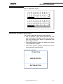
Using the Alphanumerical Keypad
Prior to starting a test in summary or monitoring
reporting mode, the operator can enter a filter/location
ID using the integrated alphanumeric keypad. The
operator must press the keypad function key to bring
up the keypad on the screen.
Navigate to a character using the arrow keys and
press Enter to select it. To toggle between the alpha
and numerical keypads, select the “1 2 3” or the “A B
C” selection and press Enter.
When the operator has finished entering his selection,
he may select the enter key “” or the “Exit” key.
Aerosol Photometer - 2i
43
Aerosol Photometer
Figure 9: Alphanumeric Keypad
A
K
,
1
B
L
T
2
C
M
U
3
D
N
V
S
E F
O P
W X
P A C
G
Q
Y
E
H I
R S
Z .
E x i
J
t
1
$
<
A
2
~
>
B
3
!
{
C
4
@
}
S
5 6
# %
[ ]
P A C
7
^
:
E
8 9
& *
; `
E x i
0
t
General Screen Structure
The screen is generally divided in three sections:
The top section of the screen provides the user
with an indication of the date and time as well as an
icon tray indicating the status of peripherals and
some setup selections.
The middle section contains the actual menu items
or the penetration display.
The bottom section contains quick access to the
most commonly used functions.
Figure 10: Screen Structure
TOP SECTION
MIDDLE SECTION
BOTTOM SECTION
Aerosol Photometer - 2i
44
Aerosol Photometer
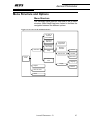
Menu Structure and Options
Menu Structure
The following figure gives an overview of the 2i menu
structure. Menu depth has been limited to facilitate the
navigation between the different options.
Figure 11: Overview of the 2i Menu Structure
Set 100% to
Upstream
Concentration
Set Internal
Reference
Use Previous
100% Setting
Main Menu
Aerosol Noise
Suppression
Reporting
Functions
Setup
Date & Time
Set Time
Set Date
Set Format
Running
Mode
Re-establishing
Zero
Language
Display
Reagent
Decimal
Alarm Set Point
Alarms
Aerosol Photometer - 2i
45
Aerosol Photometer
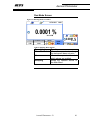
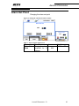
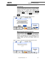
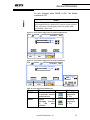
Run Mode Screen
Figure 12: Running Mode Screenshot
16 Feb 2012
09:59
0.0001 %
28.3 ALPM
Reagent
Alarm Set Point
PAO
0.001
Alarms
0.0001 %
Home
Menu
28.3 ALPM
PAO
Table 5: Running Mode Options
Description
Alarm Set Point
Alarms
Sampling
Function
Allows the operator to change
the instrument alarm set point.
Allows the operator to select
which alarms are enabled.
Allows the operator access to
the Main Menu.
Aerosol Photometer - 2i
46
Aerosol Photometer
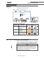
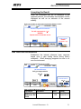
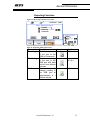
Top Level Menu Options
Figure 13: Main Menu Screenshot
16 Feb 2012
09:59
Main Menu
Set 100% to Upstream Concentration
Set Internal Reference
Use Previous 100% Settings
Setup
Re-establishing Zero
Reagent
Alarm Set Point
PAO
0.001
Alarms
Sampling
Set 100% Upstream
Set Internal Ref
Previous Settings
Setup
Re-Zero
PAO
Table 6: Main Menu Options
Description
Set 100% to
Upstream
Concentration
Set Internal
Reference
Use Previous
100% Settings
Setup
Re-establishing
Zero
Reagent
Function
.
.
.
.
.
Aerosol Photometer - 2i
47
Aerosol Photometer
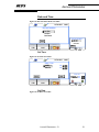
Alarm Set Point
Changing the alarm set point
Figure 14: Setting the Alarm Set Point Screenshot
16 Feb 2012
09:59
Alarm Set Point
0.001
Cancel
Default
Reagent
Alarm Set Point
PAO
0.001
Alarm Set Point
Save
0.001
Alarms
Default
PAO
Table 7: Alarm Set Point Options List
Parameter
Alarm Set
Point
Function
Icon
Change the alarm
threshold for %
N/A
leakage.
Aerosol Photometer - 2i
Limits
0.001 to 100
48
Aerosol Photometer
Alarms
Changing the alarms selection
Figure 15: Setting the Alarms Screenshot
16 Feb 2012
09:59
Alarm Selection
Audible
Vibratory
Visual
Cancel
Default
Reagent
Alarm Set Point
PAO
0.001
Save
Alarms
Select Alarm
Audible
Vibratory
Visual
Default
PAO
Table 8: Alarm Selection Options List
Parameter
Audible
Vibratory
Visual
Icon
enabled
Function
Icon
disabled
Audible alarm on
the base unit and
the probe.
Vibratory alarm in
the probe
Visual alarm on the
screen of the base
unit and the probe
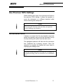
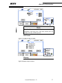
Set 100% to Upstream Concentration
When selecting this method to setup the instrument,
the user is guided through the process by a series of
screen. This section describes the different screens.
Note
i
It is unnecessary to change the internal reference value
when setting the 100% upstream concentration. The
internal reference is set to 100ug/L for the reagent in use
for display on the LCD main screen. This method is
different than the 2G nad 2H models.
Aerosol Photometer - 2i
49
Aerosol Photometer
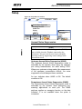
Instructions
This first screens instruct the user to verify the reagent
selection as well as the aerosol line connection to the
upstream port. To continue with setting up the
instrument to the upstream aerosol, select Proceed
and press Enter. To return to the main menu and
change you selection, select Back button and press
Enter.
Figure 16: Set 100% to Upstream Concentration Initial Screenshot
16 Feb 2012
09:59
Measure Upstream Concentration
Connect 100% line to the Upstream port.
Verify you Reagent Selection
Select Proceed when done or Exit to
change your 100% Reference selection.
Back
Proceed
Reagent
Alarm Set Point
Alarms
PAO
0.001
Measure Upstream
Connect 100% Line
Verify Reagent
Back
Sampling
Proceed
PAO
Measuring the Upstream Aerosol
After the operator selects Proceed, the instrument will
attempt to set its 100% reference to the upstream
aerosol. An animated icon will be displayed on the
screen during this operation. During this operation, the
reagent, alarm set point and alarms options are
disabled.
Figure 17: Set 100% to Upstream Concentration Measurement Screenshot
16 Feb 2012
09:59
Measure Upstream Concentration
Reading Upstream Concentration
Measure Upstream
Reading Upstream
Concentration
Reagent
Alarm Set Point
PAO
0.001
Alarms
Aerosol Photometer - 2i
Sampling
PAO
50
Aerosol Photometer
Accepting the Result
Once the instrument has set its reference to the
upstream aerosol, the calculated concentration will be
displayed as well as an estimate of the aerosol
stability.
Figure 18: Set 100% to Upstream Concentration Final Screenshot
16 Feb 2012
09:59
Set 100% to Upstream Concentration
The 100% concentration is: 2 g/L
WARNING
Upstream aerosol concentration too low
Set 100% Upstream
WARNING
Concentration < 5 g/L
Back
Reagent
Alarm Set Point
PAO
0.001
Alarms
Sampling
Back
PAO
Set Internal Reference
Establishes the internal reference base response
based upon a gain setting stored during factory
calibration. When changing reagents be sure to rezero the instrument.
Figure 19: Set Internal Reference Screenshot
16 Feb 2012
09:59
Set Internal Reference
Verify your reagent selection
100 g/L
Set Internal Reference
Back
Proceed
Reagent
Alarm Set Point
Alarms
PAO
0.001
100 g/L
Back
Sampling
Proceed
PAO
Table 9: Internal Reference Set Point
Parameter
Function
.
Internal
Reference Set
Point
Aerosol Photometer - 2i
Icon
N/A
Limits
5 to 120
Increment of
1
51
Aerosol Photometer
Use Previous 100% Settings
When selecting this option, the instrument will reset to
the previous 100% setting. It allows the operator to
move the instrument to a different electrical outlet
while minimizing the startup time.
i
Note
When using this function, make sure that your upstream
aerosol challenge stays identical.
Re-establish Zero
If there is a concern that the zero baseline may have
drifted, the operator may re-zero the instrument at any
time by selecting this option form the main menu.
The highlighted selection will flash until the instrument
has completed the re-zeroing process. Once the
operation is complete the display will revert back to
displaying the leakage value.
i
Note
When the instrument drifts too far from zero a warning will
be displayed asking if the user would like to re-establish the
zero.
Aerosol Photometer - 2i
52
Aerosol Photometer
Setup
Figure 20: Setup Menu Screenshot
16 Feb 2012
09:59
Setup
Aerosol Noise Suppression
Reporting Functions
Date & Time
Display
UANS/DANS
Reporting Functions
Date and Time
Display
Back
Reagent
Alarm Set Point
PAO
0.001
Alarms
Back
PAO
Aerosol Noise Suppression
Note
i
The Downstream Aerosol Noise Suppression (DANS) is
not available when the iProbe is connected to the
instrument. This prevents the user from accidentally
skewing results by suppressing actual readings in the
downstream mode.
Upstream Aerosol Noise Suppression (UANS)
The Upstream Aerosol Noise Suppression mode is
selectable by the operator when using the upstream
port during measurement, not while setting 100%.
When poor upstream mixing makes the measurement
of the upstream concentration difficult, the noise
suppression should dampen these variations.
An icon indicates when UANS is ON. The default
condition is ON.
Downstream Aerosol Noise Suppression (DANS)
The Downstream Aerosol Noise Suppression mode is
selectable by the operator when performing nonscanning applications on each port. The DANS
performs applies an averaging function on the data
collected. It is not available when the probe is
connected.
Aerosol Photometer - 2i
53
Aerosol Photometer
An icon indicates when DANS is ON. The default
condition is OFF.
Note
i
When the operator connects the probe, the DANS function
will automatically be disabled if it was previously selected.
This will preserve the integrity of the test results while
performing a filter scan.
Figure 21: Aerosol Noise Suppression Screenshot without Probe
16 Feb 2012
09:59
Setup – Aerosol Noise Suppression
Upstream (UANS)
Downstream (DANS)
Cancel
30s
10s
Default
Reagent
Alarm Set Point
PAO
0.001
Save
Alarms
Figure 22: Aerosol Noise Suppression Screenshot with Probe
16 Feb 2012
09:59
Setup – Aerosol Noise Suppression
Upstream (UANS)
Cancel
30s
Default
Reagent
Alarm Set Point
PAO
0.001
Save
Noise Suppression
UANS
30s
Alarms
Default
PAO
Table 10: Noise Suppression Options List
Parameter
UANS
DANS
Function
Icon
Dampens variations
in upstream aerosol
measurements
Applies
an
averaging function
on
the
data
collected.
Aerosol Photometer - 2i
Limits
30 to 120 s
Increments
of 10 s
10 to 30 s
Increments
of 10 s
54
Aerosol Photometer
Reporting Functions
Figure 23: Reporting Functions Screenshot
16 Feb 2012
09:59
Setup – Reporting Functions
Cancel
Summary
Monitoring
Continuous
0.8
Default
Reagent
Alarm Set Point
PAO
0.001
Save
Alarms
Reporting Functions
Summ.
Monit.
0.8
Cont.
Default
PAO
Table 11: Reporting Mode Options List
Parameter
Summary
Monitoring
Continuous
Function
Icon
Provides a summary
of the test to the
USB or Printer port.
Provides a summary
of the test to the
USB port with data
sets at user defined
intervals.
Provides
a
%
leakage reading to
the USB port at
approximately a 1
second interval
Aerosol Photometer - 2i
Limits
N/A
Increments
of 0.4 s
N/A
55
Aerosol Photometer
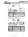
Date and Time
Figure 24: Date and Time Menu Screenshot
16 Feb 2012
09:59
Date and Time Menu
Set Time
Set Date
Set Format
Date and Time Menu
Set Time
Set Date
Set Format
Back
Reagent
Alarm Set Point
PAO
0.001
Alarms
Back
PAO
Set Time
Figure 25: Set Time Screenshot
16 Feb 2012
09:59
Setup – Time
HOUR
MINUTE
09
59
Cancel
Save
Reagent
Alarm Set Point
PAO
0.001
Setup Time
HOUR
09s
MINUTE 59s
Alarms
PAO
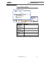
Set Date
Figure 26: Set Date Screenshot
Aerosol Photometer - 2i
56
Aerosol Photometer
16 Feb 2012
09:59
Setup – Date
Year
Month
Date
2012
02
16
Cancel
Setup Date
YYYY
2012
MM
02
DD
16
Save
Reagent
Alarm Set Point
PAO
0.001
Alarms
PAO
Note
i
The 2i will automatically verify the entered date for
compliance with leap years. If the date entered does not
comply, the entry will be rejected.
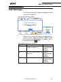
Set Format
Figure 27: Set Date Format Screenshot
16 Feb 2012
09:59
Setup – Format
Cancel
DD mmm YYYY
mmm DD YYYY
MM/DD/YYYY
DD/MM/YYYY
Default
Reagent
Alarm Set Point
PAO
0.001
Save
Alarms
DD mmm YYYY
mmm DD YYYY
MM/DD/YYYY
DD/MM/YYYY
Default
PAO
Display
Figure 28: Display Setup Screenshot
Aerosol Photometer - 2i
57
Aerosol Photometer
16 Feb 2012
09:59
Setup – Display
Language
Monitor
Setup Display
Language
Monitor
Back
Reagent
Alarm Set Point
PAO
0.001
Alarms
PAO
Table 12: Date and Time Menu Options List
Parameter
Language
Function
Change the default language the unit
operates in.
Menu to change the screen setup.
Monitor
Figure 29: Display Setup Screenshot
16 Feb 2012
09:59
Setup – Display
Decimal
Base Brightness
Probe Brightness
Cancel
4
100
100
Default
Reagent
Alarm Set Point
PAO
0.001
Setup Display
Decimal
4
Bright 2i 100
Bright Pr 100
Save
Alarms
Default
PAO
Table 13: Date and Time Menu Options List
Parameter
Decimal
Base
Brightness
Probe
Brightness
Function
Displays the % Penetration with
three or four decimal places.
Adjust the base unit screen
brightness.
Adjust
the
iProbe
screen
brightness.
Aerosol Photometer - 2i
Limits
3 or 4
25, 50, 75,
100
25, 50, 75,
100
58
Ae
erosol Ph
hotomete
er
Errror Mes
ssages
The 2i has
s multiple e
error or abn
normal operration checcks
built into the software
e.
Figure 30: Error Messag
ge Screenshot
166 Feb 2012
009:59
WARNING – Equipment Faailure
Check Sample Line for Blocckage
Error
E
E1
OK
Reagent
Alarm Set Po
oint
PAO
0.001
Alarm
ms
Samppling
Eqquipment Failure
P
Pump Blockage
Error E1
OK
Serial N
Number: XXXXX
When an error occu rs, the ope
erator is pro
ompted forr a
oftware generated ala
arms requiire
course off action. So
the opera
ator acknow
wledgemen
nt to proce
eed. This is
done by pressing
p
the
e OK button
n.
L of Operattor Error Messsages
Table 14: List
Error ID
D
E1
E2
E3
Rea
ason
Rem
medy
Obs
struction in
n the line. Max Refe
er to
Pum
mp flow rea
ached
troub
bleshooting
g
guide
e in
appe
endix
Unit too hott or cold for Refe
er to
ope
eration
troub
bleshooting
g
guide
e in
appe
endix
PMT error call ATI
Refe
er to
troub
bleshooting
g
guide
e in
appe
endix
Aerosol Photometerr - 2i
559
Ae
erosol Ph
hotomete
er
CH
HAPTER 7
Ap
pplica
ation Notes
s
Abbreviattions Liist
Table 15: Ab
bbreviations L
List
Abbrevia
ation
g
l
µ
m
µg/l
mg/m3
lpm
STP
LSC
Mean
ning
Gram
ms
Liter
micro
o (1x10⁻⁶)
milli ((1 x 10⁻³)
micro
ograms perr liter
millig
grams per ccubic meterr
liters per minute
e
stand
dard temperature and pressure
light sscattering cchamber
Aerrosol Correcti
C
ion Fac
ctors
The value
es are for use when
n substitute
e liquids a
are
used in-place of the
e liquid sp
pecified forr the Facto
ory
equipment calibration
n and setup
p.
Aerosol Correction
C
F
Factors use
ed in the 2i are specifie
ed
in the follo
owing table :
Table 16: Aeerosol Correcttion Factors L
List
PAO
O Substitute
e Liquid
DOP (DE
EHP)
PAO (Em
mery 3004)
DOS (DE
EHS)
Mineral Oil
O
User Deffined
Kaydol
Polyethylene Glycoll (PEG400))
Paraffin Oil
O
Corn Oil
Ondina
Finevesta
an
Aerosol Photometerr - 2i
PAO
O Internal
Refere
ence Setting
g
100
0.73
0.96
0.90
0.92
1.11
0.89
0.88
-
660
Ae
erosol Ph
hotomete
er
CH
HAPTER 8
Ma
aintaining the Photom
P
meterr
Deffinition
ns and Feature
F
es
The 2i Aerosol
A
Pho
otometer is a sturdyy, solid-sta
ate
electronic instrumen
nt designe
ed to hold
d up und
der
parts are th
he
extended field use. The onlyy moving p
p
the selector va
alve and th
he ventilatin
ng
vacuum pump,
fan at the rear of the
e chassis. F
Field level maintenancce
is limited to replacem
ment of the
e fuses and
d cleaning of
creens. Pro
ocedures fo
or these op
perations a
are
the lint sc
contained in this secttion.
i
Note
The interrnal electronnics are noot user servviceable. Anny
electronicc problems m
must be anaalyzed and rrepaired at aan
authorized
d service cennter.
a defined as follow:
Intervals are
Day
8 hours of o
operation
4
40 hours off operation
Week
2
2080 hourss of operatio
on
Annual
Rec
comme
ended Schedu
S
uled Ma
aintenan
nce1
Daily
Clean the aeroso l ports scre
eens. Thesse are
located
d in the blacck circular aerosol porrt connecto
or
on the front panel of the maiin unit.
Remov
ve any loosse debris fro
om the Sca
anning Prob
be
and fro
ont panel sa
ampling ports.
Annually
y
Return th
he 2i to a factory authorized
d facility ffor
calibration
n and cle
eaning. Ple
ease conta
act the A
ATI
Customerr Service De
epartment at (410) 36
63-9696 forr a
1
Repllacement parts are available from
f
ATI. For part
p numbers, rrefer to Table 18: Maintenannce and Spare
Items page 72
Aerosol Photometerr - 2i
661
Aerosol Photometer
return authorization number. A service date will be
scheduled for your instrument at that time.
Note
A Return Authorization can also be obtained using ATI’s
website or by sending an e-mail requesting service
information to [email protected]. A customer service
representative will process your information and contact
you with a Return Authorization, necessary instructions
and information within 48 hours.
i
Replacing the Main Power Fuses
Disconnect the power cord from the machine and from
electrical source.
Using a small flat blade screwdriver, open the fuse
cover and remove the fuse holder from the power inlet
module.
Remove old fuses and install two new fuses with ATI
part number according to Table 17: Replacement
Fuses for the 2i.
Replace the fuse holder by gently inserting it back into
the power inlet module until the tabs snap back into
their original location.
Close the fuse cover.
Reconnect the power cord
Table 17: Replacement Fuses for the 2i
For 115 V or ATI Part Number 6400001
220 V
(5 X 20 mm, 2A, 250V, SLOW BLO)
Cleaning the Lint Screens
The aerosol port connectors on the main unit contain a
wire screen to prevent fibers and large particles from
being drawn into the photometer. If the screens
accumulate a significant amount of debris and become
partially clogged, it can interfere with the airflow and
affect the accuracy of the photometer and may put an
unnecessary strain on the vacuum pump.
i
Note
Aerosol Photometer - 2i
62
Aerosol Photometer
It is recommended that all screens be wiped clean with a
lint-free cloth before use each day.
If the screens are punctured, replace them
immediately. Spare nozzles and replacement scanning
probe components can be ordered from ATI (see
“APPENDIX E Maintenance and Spare Items” page
72).
Aerosol Photometer - 2i
63
Ae
erosol Ph
hotomete
er
CH
HAPTER 9
Tro
ouble
eshoo
oting Guide
G
e
i
i
Note
If any re
emedy liste
ed is not efffective, contact ATI forr
repair servvice.
Note
N
– Baattery Information
The batterry type usedd in the 2i Aeerosol Photometer is a 3V
V
lithium ion battery typpe CR2032.
Ins
strumen
nt Will Not
N Pow
wer Up
Prob
bable Caus
se
Power cab
ble not plugge
ed in
Fuse blown
n
Reme
edy
Plug
g power cable
e into an
appropriate powe
er outlet
Che
eck system fuse(s)
Errror E1 – Samp
ple Line
e Blocka
age
Prob
bable Caus
se
Reme
edy
Excessive debris in lint
screen.
An object has
h been pull ed
into the line
e by vacuum pump.
Che
eck lint screen
n in hose
adapter and clea
an if necessarry.
Insp
pect probe an
nd umbilical fo
or
fore
eign object. R
Remove objecct,
if po
ossible.
Movve the probe tto an area fre
ee
of obstructions th
hat could
prevvent flow thro
ough the
instrrument.
Calll ATI for service.
Probe nozz
zle obstructed
d.
Pressure trransducer or
thermistor damaged.
Aerosol Photometerr - 2i
664
Aerosol Photometer
Error E2 – Out of Temperature Range
Probable Cause
Remedy
Ambient temperature is below
1°C or above 40°C.
Thermistor damaged.
Probe nozzle obstructed.
Move instrument to
temperature in the range.
Call ATI for service.
Move the probe to an area free
of obstructions that could
prevent flow through the
instrument.
Error E3 – Photomultiplier Tube (PMT) Inoperable
Probable Cause
No voltage to PMT
Scattering chamber dirty or
contaminated.
Aerosol Photometer - 2i
Remedy
Call ATI for service.
Call ATI for service.
65
Aerosol Photometer
APPENDIX A
Contacting ATI
For Technical Support or Application Questions
If you experience any difficulty setting up the 2i
Photometer or have application questions, contact
ATI at (410) 363-9696 or via email at
[email protected].
For Customer Service
If the 2i Photometer is not operating properly, or if you
are returning the instrument for service, contact ATI
Customer Service at (410) 363-9696 or by email at
[email protected]. Customer Service will need this
information when you call:
The Aerosol Photometer serial number located on
the Instrument Identification on the back of the
machine (see “Rear Panel General Overview”
page 27).
A purchase order number (unless under warranty)
A billing address
A purchasing point of contact
A technical point of contact
A shipping address
The preferred return shipping carrier
Use the original packing material to return the
generator to ATI. If you no longer have the original
packing material, you can order it from ATI or use
sufficient packing material so the generator is not
damaged during shipping.
Aerosol Photometer - 2i
66
Aerosol Photometer
APPENDIX B
Warranty
Part Number
Address
Phone No.
Fax No.
E-mail Address
Limitation of
Warranty and
Liability
1800224 / Revision 1 / March 2012
Air Techniques International / 11403 Cronridge Drive / Owings
Mills, MD 21117 / USA
(410) 363-9696
(410) 363-9695
[email protected]
Air Techniques International, hereinafter referred to as ATI,
warrants the equipment purchased hereunder to be free from defect
in materials and workmanship under normal use and service, when
used for the purpose for which it is designed, for a period of (1) one
year from the date of shipment. ATI further warrants that the
equipment will perform in accordance with the technical
specifications accompanying the formal equipment offer.
ATI will repair or replace any such defective items that may fail
within the stated warranty period, PROVIDED:
a. That any claim of defect under this warranty is made within
thirty (30) days after discovery thereof and that inspection
by ATI, if required, indicates the validity of such claim to
ATI’s satisfaction.
b. That the defect is not the result of damage incurred in
shipment to or from our factory.
c. That the equipment has not been altered in any way whether
as to design or use, whether by replacement parts not
supplied or approved by ATI, or otherwise.
d. That any equipment or accessories furnished but not
manufactured by ATI, or not of ATI design, shall be subject
only to such adjustments as ATI may obtain from the
supplier thereof.
ATI’s obligation under this warranty is limited to the repair or
replacement of defective parts with the exception noted above. If
the equipment includes a scattering chamber, ATI’s warranty does
not extend to contamination of the scattering chamber by foreign
material.
At ATI’s option, any defective equipment that fails within the
warranty period shall be returned to ATI’s factory for inspection,
properly packed with shipping charges prepaid. No equipment
Aerosol Photometer - 2i
67
Aerosol Photometer
shall be returned to ATI without prior issuance of a return
authorization by ATI.
Service Policy
No warranties, express or implied, other than those specifically set
forth herein shall be applicable to any equipment manufactured or
furnished by ATI and the foregoing warranty shall constitute the
Buyer’s sole right and remedy. In no event does ATI assume any
liability for consequential damages, or for loss, damage or expense
directly or indirectly arising from the use of ATI products, or any
inability to use them either separately or in combination with other
equipment or materials or from any other cause.
Our service policy is designed to give prompt attention to any
problems. If you encounter a defective product or discover a
malfunction, please call ATI Customer Service to obtain a return
authorization at (410) 363-9696.
Aerosol Photometer - 2i
68
Aerosol Photometer
APPENDIX C
Declaration of Conformity
We:
AIR TECHNIQUES INTERNATIONAL
11403 Cronridge Drive
Owings Mills, Maryland 21117-2247
USA
Tel: (410) 363-9696
Fax: (410) 363-9695
Website: http://www.atitest.com
Declare under our sole responsibility that the product,
2i Photometer
Manufactured beginning April, 2012
is in conformity with the following directives:
Application of Council Directive(s)
Standard(s) to which
Conformity is Declared
EN61326-1:2006
EN61000-3-2:2006
EN61000-3-3:2006
EN61010-1:2010
Electromagnetic Compatibility Directive
(2004/108/EC)
Low Voltage Directive (2006/95/EC)
Design documentation is maintained at:
Air Techniques International
11403 Cronridge Drive
Owings Mills, Maryland 21117-2247
USA
Eric Hanson
President
Date of Issue:
Place of Issue:
15 April 2012
Owings Mills,
Air Techniques International
Maryland 21117-2247
USA
Aerosol Photometer - 2i
69
Aerosol Photometer
APPENDIX D
Specifications
Main Unit Physical Characteristics
Dimension (L x
W x H)
Weight
15.2 cm (6 in) x 15.2 cm (6 in) x
33 cm (13 in)
8.6 kg (19 lb)
Operational Requirements
Power
Electrical Fuses
115 VAC, 60 Hz, .5 Amps
220 VAC, 50 Hz, .25 Amps
Two Required, 5 x 20 mm, 2A,
250V, SLOW BLO
Operating Conditions
Ambient
Temperature
Ambient
Humidity
Ambient altitude
Storage
requirements
10ºC to 35ºC
5% to 95% (non-condensing or
icing)
From 0 to 10,000 ft
-20 to 60º C
Less than 95% Relative Humidity
non-condensing
Aerosol Detection
Technique
Dynamic Range
Sample Flow
Rate
Near Forward Light Scattering
Photometer
0.0001 to 120 mg/m3
Full flow through detection
28.3 liters per minute volumetric
Data Output Formats
USB Port
Thermal Printer
9600,8,1,N
Thermal Paper, 57 mm (2 ¼ in)
wide
Aerosol Photometer - 2i
70
Aerosol Photometer
Outputs
Display
Communication
10.9 cm (4.3 in) LCD screen
USB Port
Aerosol Photometer - 2i
71
Aerosol Photometer
APPENDIX E
Maintenance and Spare Items
Table 18: Maintenance and Spare Items
Part Number Description
0800217
5200116
6700001
T2E0-0063
6400001
4300236
1000445
2500123
5100001
5100002
5100004
5100101
T2E0-0005
T2E0-0572
T2E0-0798
Scanning Probe Umbilical
¼” ID PVC sample tubing (specify
length)
Replacement Line Cord, 120V (USA)
Replacement Line Cord, 220V (Europe)
Fuse, 2 amp, 5 x 20 mm
Base Unit Quick-Connect O-ring
Lint Screen
Thermal Paper (1 roll)
Probe - Segment
Probe - Male threaded end segment
Probe - Female threaded end segment
Probe - Male close nipple
Probe - NSF 49:1992 nozzle
Probe - 1” Isokinetic, round (red)
Probe - NSF 49:2002 Isokinetic,
rectangular (blue)
Aerosol Photometer - 2i
Suggested
Quantity
1 ea
12 ft
1 ea
1 ea
2 ea
2 ea
2 ea
1 ea
3 ea
1 ea
1 ea
1 ea
1 ea
1 ea
1 ea
72
Aerosol Photometer
APPENDIX F
Accessories
Scanning Probe
The scanning probe allows the remote
operation of the 2i. It allows access to virtually
all the functionalities of the base unit from a
convenient remote location.
Thermal Printer Module
The Thermal Printer module is designed to
provide certifiers with a mean to maintain test
results traceability.
Transport Case
The rugged Transport Case with its custom
foam offers the best protection available for
the 2i and its accessories for shipment or daily
use.
Table 19: Accessories List
Description
Scanning Probe
Thermal Printer
Transport Case
Aerosol Photometer - 2i
Part Number
9300236
0200477
9300243
73
Aerosol Photometer
APPENDIX G
Manual Revision History
The following is a revision history of the Operation
and Maintenance Manual, P/N 1800224
Table 20: Manual Revision History
Revision
A
B
C
D
E
Date
Description
04/24/2012
5/31/2012
2/1/2013
Updated electrical power requirement on page 22, changed
ACFM to ALPM on page 33, updated monitoring mode
data to show 0.4s increments on page 38, added remark
about re-zeroing the instrument after a reagent change on
page 51, updated table to show 0.4s increments in
monitoring, aerosol correction factors updated on page 60.
12/9/2014 Ondina & Finevestan added to reagent selection menu
05/04/2015 Removal of Printer from Monitoring mode section: Table
11, Page 55.
Aerosol Photometer - 2i
74
Aerosol Photometer
APPENDIX H
Español – Precauciones
!
i
!
Advertencia – Reglas Generales de
Seguridad
Lea y comprenda todas las instrucciones. La falta de
seguimiento de todas las instrucciones listadas abajo podrá
ocasionar una descarga eléctrica, fuego o una seria lesión
personal. Las advertencias, cautelas y las instrucciones
discutidas en este manual de operación y mantenimiento
pueden no cubrir todas las posibles condiciones y situaciones
que podrían presentarse. El operador debe entender que el
sentido común y la cautela son factores que no pueden
incorporarse al equipo por lo que deben ser suministrados por
el operador.
Advertencia – Riesgos del transporte
.
Cautela – Mantenimiento
!
!
Cuando reinserte el portafusibles en el módulo de
alimentación de energía, verifique que se haya seleccionado
el voltaje apropiado para su red eléctrica. El reemplazo
incorrecto del fusible puede dañar a los componentes internos
del equipo.
Advertencia – Riesgo Eléctrico
• Riesgo eléctrico que puede ocasionar lesiones severas
o la muerte.
• El compartimento eléctrico contiene múltiples fuentes
de alto voltaje. No inserte ningún objeto bajo la cubierta.
!
Advertencia –Equipo Dañado
Aerosol Photometer - 2i
75
Aerosol Photometer
No opere el equipo con el cable o el conector dañados
o luego de que el equipo ha sufrido un mal
funcionamiento o ha sido dañado de cualquier
manera.
Contacte al Departamento de Servicio de ATI para
obtener consejos de revisión, de reparación o de
ajustes eléctricos o mecánicos.
La falta en el seguimiento de los procedimientos
prescriptos puede producir una situación riesgosa
Aerosol Photometer - 2i
76
Aerosol Photometer
APPENDIX I
Français – Précautions
!
i
!
!
!
Avertissement – Règles générales de
sécurité
Lire et comprendre toutes les instructions. Ne pas suivre les
instructions listées ci-dessous peut engendrer un choc
électrique, un incendie ou des blessures graves. Les mises en
garde, avertissements, précautions et instructions détaillées
dans ce manuel d’utilisation et de maintenance ne peuvent
pas couvrir toutes les situations et conditions pouvant se
produire. L'opérateur doit comprendre que le bon sens et la
prudence sont des facteurs qui ne peuvent pas être intégré à
cet équipement et doivent donc être apportés par l’opérateur.
Précaution – Risque lié au transport
Précaution – Maintenance
Le remplacement incorrect des fusibles peut endommager les
composants internes de l'appareil.
Avertissement – Risque électrique
Les risques électriques peuvent causer des blessures
graves, voire mortelles.
La partie électrique contient plusieurs sources à haut
voltage. N’insérez aucun objet sous le couvercle.
!
Avertissement - Equipment
endommagé
Ne pas faire fonctionner l'appareil avec un câble
d’alimentation ou une prise endommagée ou après que
l'équipement ait mal fonctionné ou a été endommagé de
Aerosol Photometer - 2i
77
Aerosol Photometer
quelque façon.
Contactez le département Service de chez ATI pour
obtenir des conseils sur l'examen, la réparation,
l'ajustement électrique ou mécanique
Ne pas suivre les procédures prescrites peut aboutir à une
situation dangereuse.
Aerosol Photometer - 2i
78
Aerosol Photometer
APPENDIX J
中文 – 预防
!
i
警告 – 安全规则概要
阅读并理解所有的指导。不按照下面的指导可能会造成
被电击,火灾或严重的个人身体伤害。这些警告,小心
和在操作和维护说明书中谈到的指导不能涵盖所有的可
能发生的危险的条件和环境。但必须理解安全常识和谨
慎操作是一个不能建立在机器里的,必须由操作员决定
的事情。
小心 – 运输危险
!
!
!
小心 – 维护保养
不正确的保险丝更换后,可能会损坏内部的自动过滤器
测试仪的零件。
警告 – 触电
触电会引起严重的伤害甚至死。
电力供应盒包括多个高压电源,不要塞任何东西在电
源供应盒的盖子下面。
Photometer - 2i
79
Aerosol Photometer
警告 – 损坏的设备
当这个设备被损坏,有故障后,或者有一个损坏的电
!
线或插头后不要操作这个设备。
联系ATI的服务部门要求给一个建议,怎样检查,维
修,电子或机械的调整等。
不按照规定的程序可能会造成危险的情形。
Photometer - 2i
80
Aerosol Photometer
APPENDIX K
Svenska – Försiktighetsåtgärder
!
i
!
!
!
Varning – Allmänt
Läs och förstå alla instruktioner. Fel i handhavandet kan
resultera i elektrisk stöt, brand eller alvarlig personlig skada.
Alla varningar som anges i denna instruktion kan inte täcka
alla eventuella uppkomna situationer. Det är därför helt
avgörande att operatören är medveten om dessa risker
Varsamhet – Transportrisk
.
Varsamhet – Underhåll
Felaktig säkring kan ge alvarliga skador på filtertestaren.
Varning- Elektrisitet
!
En elektronisk stöt kan innebär alvarlig skada eller
död.
I elektroniken och nätdelen finns högspänning. För
aldrig in någonting under skyddskåpan.
Varning- Skada apparat
Kör aldrig enheten med skada sladd, kontakt eller vid
annan felaktighet på enheten.
Kontakta alltid ATI för rådgivning vid skada eller vid
reparation och justering.
Att inte följa dessa instruktioner kan medföra stor
skada.
Photometer - 2i
81
Aerosol Photometer
Photometer - 2i
82
Aerosol Photometer
Notes:
Air Techniques International
11403 Cronridge Drive, Owings Mills, MD 21117-2247 U.S.A.
Web: www.atitest.com