1
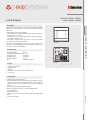
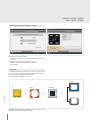
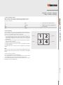
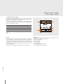
HD4685 - HC4685 - HS4685
L4685 - N4685 - NT4685
Local display
LOCAL DISPLAY is an OLED Touch Screen technology control and management DEVICE
FOR The scenario control, temperature control, and sound system functions of the MY
HOME system.
Integration with the device is simple and intuitive:
- when the display is touched, a click is emitted through the internal loudspeaker, and
the display comes on for 30 seconds;
- if the display is OFF, or a screensaver is playing, the first touch will cause the display to
activate without sending any controls;
- If the display is already active, the corresponding icon becomes coloured while
pressed, and the associate control is performed.
On the lower section of Local Display is a serial connector for connection of the device to
a PC, using the USB 3559 programming accessory, for updating the configuration, the
set of characters and icons, and the firmware.
1
Front view
Technical data
- Power supply from BUS:
27 Vdc
- Operating power supply with SCS BUS: 18 – 27 Vdc
- Stand-by Absorption:
20 mA (max)
- Operating absorption:
60 mA (max)
- Operating temperature:
5 – 35 °C
- Size:
2 flush mounted modules
Legend
1.
2.
3.
4.
5.
ZA/A
ZB PL/PF
MOD
FUN
5
2
3
Rear view
TECHNICAL SHEETS - AUTOMATION
Description
4
OLED technology Touch Screen
Configurator socket
BUS clamp
Clamp for the connection of the external temperature probe
Serial connector
Configuration
BT00193-c-UK
Local Display may be configured in two ways:
- physical configuration, by connecting the configurators to the appropriate sockets. The
configurators can only be used to select the type of function. To set other parameters
it will be necessary to connect Local Display to the PC and use the TiLocalDisplay
Software.
- from the PC, using the dedicated TiLocalDisplay software.
Based on the configuration set, the device can work in four different modes:
- Scenario control mode
- With external probe 3457
- Temperature control probe mode with HC4693, HS4693, L4693, N4693, NT4693
probe.
- Sound system control mode
1
HD4685 - HC4685 - HS4685
L4685 - N4685 - NT4685
TiLocal Display Software sample screenshots
Main possible functions using the software:
- Selection of the operating mode to set for the device, temperature control, scenarios,
sound system.
- Configuration of the settings of the probe and of its parameters.
- Configuration of the general device parameters (e.g. screensaver).
- Icon style definition.
Installation
Local Display is installed using a traditional procedure, using a box, support, and cover
plate (*); the device is not fitted with a temperature probe. Therefore, it will not be
necessary to comply with the probe installation requirements.
The recommended installation height is 150 - 160 cm.
Cover plate
Box
Support
+
Local display
+
BT00193-c-UK
(*) NOTE: AXOLUTE, LIVING, LIGHT and LIGHT TECH series boxes, supports, and cover
plates can be found in the General installation catalogue.
2
+
HD4685 - HC4685 - HS4685
L4685 - N4685 - NT4685
A
Room
0 – 9, room of the scenario module item F420
PL
Light point
1 – 9, light point of the scenario module item F420
MOD
Mode
0 – 8, scenario number
FUN
Function
3
Scenario programming
To program, change or delete a scenario, the programming of Module item F420 must be
enabled, confirmed by the programming status LED turning green (press the lock/unlock key
for at least 0.5 seconds). After this has been done proceed as follows:
1) Press one of the four keys to which the scenario should be associated to for 3 seconds.
The screen shows the name and icon of the selected scenario and the programming bar,
to indicate that the learning procedure has started. If the device does not receive any
commands within 30 minutes from the start of the learning procedure, programming will
automatically stop.
2) set the scenario using the corresponding controls for the various Automation, Temperature
control, Sound system, etc. functions;
3) confirm the scenario by quickly pressing on the display
4) to change a scenario or create new ones to associate to other pushbuttons, repeat the
procedure starting from 1.
To recall an existing scenario, a quick pressure of the corresponding key on the display is
enough.
scenario 1
scenario 3
1 2
3 4
scenario 2
scenario 4
TECHNICAL SHEETS - AUTOMATION
- Scenario control mode - FUN = 1
Thanks to this mode, it will be possible to manage and change 4 different associated
scenarios of the F420 scenario module, and activate them by pressing one of the 4
icons shown on the display.
NOTE:
Once the necessary operations have been completed, block programming by pressing the
lock/unlock key of the scenario module for at least 0.5 seconds, until the corresponding LED
turns red.
To delete a scenario, proceed as follows:
1) the scenario module must be enabled for programming
2) press the pushbutton for the scenario to be cancelled for at least 10 seconds. The display
will confirm that the scenario has been deleted and return to the main screen.
To reset the whole memory from the scenario module press the DEL key for 10 seconds. The
yellow LED, “reset scenarios”, will flash quickly.
BT00193-c-UK
3
HD4685 - HC4685 - HS4685
L4685 - N4685 - NT4685
– Sound system control mode - FUN = 2
With this mode, for the associated amplifier the user can control the switching ON or OFF,
the volume, the cycling through the sources, and their management (where allowed).
Information on the currently active source is also displayed.
In this mode the parameters that can be configured are the local address of the display (which
must coincide with the A|Pf address, and the M1 mode of the associated amplifier), and the
name of the sources that can be controlled.
A
Room
0 – 9, amplifier room
PF
Loudspeaker
1 – 9, amplifier loudspeaker
MOD
Mode
0 – 4, source switching ON (*)
FUN
Function
2
1
7
RDS
106.70
6
NOTE (*): with M=0, source 1 is switched on without first switching OFF the sources (Follow Me
mode).
Functions
A quick pressure of keys 6 and 7 will respectively switch ON and OFF the associated amplifier. If
the associated amplifier is on, an extended pressure of keys 6 and 7 may be used to adjust the
volume, the intensity of which will be displayed by means of an icon 5. A short pressure of keys
2 and 4, will respectively cycle through the sources installed in the system, and launch a control
for the currently active source. If the associated amplifier is OFF and no source is on, the screen
will not show any information.
Press key 4 for 3 seconds to configure the alarm clock (see the user manual for details).
BT00193-c-UK
4
2
ON
OFF
5
Legend
1.
2.
3.
4.
5.
6.
7.
Indication of the amplifier status or radio frequency
Cycling of sources (radio/aux)
Active source indication
Change radio station
Volume level indication
Associated amplifier ON and volume increase
Associated amplifier OFF and volume decrease
2
3
4
HD4685 - HC4685 - HS4685
L4685 - N4685 - NT4685
ZA/A
ZB PL/PF
MOD
FUN
Temperature
probe
BUS - SCS
ZA
Zone address
0 – 9, Local Display address
ZB
Zone address
1 – 9, Local Display address
MOD
Mode
0 – 8, Slave probe number
FUN
Function
3
For simple systems, where each zone controls at most one heating actuator and one air
conditioning actuator, both of the ON/OFF type, and on a system with only one pump
per function, the configuration of the system can be performed by simply connecting
the configurators that identify the address of the device and, in case of probe, indicate
the number of slaves present.
Functions
A short pressure of keys 8 and 11 can be used to locally change the temperature by
+/-3 °C, in relation to the settings received from the central unit. A short pressure of
key 6 can be used to select the mode of operation, cycling through the OFF, antifreeze/
thermal protection, and automatic statuses respectively. Each mode of operation is
identified by a different icon. A short pressure of key 2 will force the speed the fan-coils,
cycling through speed 1, 2, 3 or automatic.
2
11
10
25.5°
9
26.3°
8
+ 2
2
3
4
5
6
7
BT00193-c-UK
Legend
1. Set temperature
2. Fan-Coil adjustment
3. Fan-Coil speed indication
4. Temperature variation indication
5. Fan-Coil operation indication
6. Change operating mode
7. Measured temperature
8. Decrease temperature
9. Operating mode indication
10. System status indication
11. Increase the temperature
For more complex systems, the probe can memorize the actuators to activate, and the
pumps to control on the BUS. The programming operation must be completed directly
from the central unit. The central unit can also be used for the calibration of the probe.
During the system setting stage, it will be necessary to specify the actuators used for
the heating system, and those used for the air conditioning system, as they operate in
a complementary way.
TECHNICAL SHEETS - AUTOMATION
- Temperature control probe mode with external probe - FUN = 3
An external temperature probe, item 3457, with the following characteristics, can be
connected on the back of Local Display:
- 10 KΩ at 25 °C BETA 3435
- max. length of the connection 10 metres
Local Display shows the temperature value measured by the external probe, the set
temperature value, and the local selector adjustment. The operations that may be
performed by user are:
- variation of the temperature set using the local selector,
- FAN-COIL speed management,
- operating mode management
5
HD4685 - HC4685 - HS4685
L4685 - N4685 - NT4685
- Temperature control probe mode with HC4693, HS4693, L4693, N4693, or
NT4693 sensor - FUN =4.
This mode is different from the previous one in the fact that the external probe is not
connected to LOCAL DISPLAY. Being unable to autonomously establish the temperature,
it must be associated to at least one probe, items HC4693, HS4693, L4693, N4693, or
NT4693. The user is shown the temperature value measured by the associated probes,
the set temperature value, and the adjustment of the local selector.
The possible operations for the user are the adjustment of the set temperature using
the local selector, and the change of status of the probe. In this mode, the parameters
that can be configured are the local display address (which must coincide with the ZA/
ZB address of the associated probe), the type of control of the pump, the type of mode,
and the number of slave probes.
ZA
Zone address
0 – 9, probe address
ZB
Zone address
1 – 9, probe address
MOD
Mode
0 – 8, Slave probe number
FUN
Function
4
For simple systems, where each zone controls at most one heating actuator and one air
conditioning actuator, both of the ON/OFF type, and on a system with only one pump
per function, the configuration of the system can be performed by simply connecting
the configurators that identify the address of the device and, in case of probe, indicate
the number of slaves present.
For more complex systems, the probe can memorize the actuators to activate, and the
pumps to control on the BUS. The programming operation must be completed directly
from the central unit. The central unit can also be used for the calibration of the probe.
During the system setting stage, it will be necessary to specify the actuators used for
the heating system, and those used for the air conditioning system, as they operate in
a complementary way.
Example of configuration of a zone (address 47) with Local Display and probe
item HC4693, HS4693, L4693, N4693 and NT4693
Local
display
Slave
probe
Functions
A short pressure of keys 8 and 11 can be used to locally change the temperature by +/-3
°C, in relation to the settings received from the central unit. A short pressure of key 6
can be used to select the mode of operation, cycling through the OFF, antifreeze/thermal
protection, and automatic statuses respectively.
BT00193-c-UK
6
Local Display
(HC/HS/L/N/NT4685)
Slave probe
(HC/HS/L/N/NT4693)
Socket
Configurator
Socket
Configurator
ZA
4
ZA
4
ZB
7
ZB
7
MOD
1
MOD
SLA
FUN
4
SLA
1
Each mode of operation is identified by a different icon. A short pressure of key 2 will
force the speed the fan-coils, cycling through speed 1, 2, 3 or automatic.


![MY HOME - Termorregulación y Climatización [pdf 8.9 MB]](http://vs1.manualzilla.com/store/data/006299556_1-14be3162ae9ed08da6bd190c5a4bbb16-150x150.png)