1
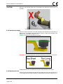
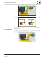
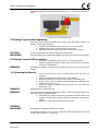
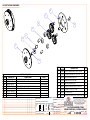
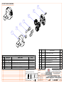
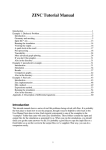
METRIC PNEUMATIC USER MANUAL TABLE OF CONTENTS TABLE OF CONTENTS ..................................................................... 1 IMPORTANT SAFETY NOTICE ......................................................... 2 1.0 General Information ................................................................ 3 1.1 System Components ................................................................... 3 1.2 Specifications ............................................................................. 3 1.2.1 Metric Specifications ........................................................................3 1.2.2 Environmental Specifications ............................................................3 2.0 Tool System ............................................................................. 4 2.1 Tool Handle Description .............................................................. 4 2.2 Regulator Cage Description ......................................................... 4 3.0 General Operating Instructions ............................................... 5 3.1 Tool Assembly ............................................................................ 5 3.2 Reaction Arm ............................................................................. 5 3.2.1 3.2.2 3.2.3 3.2.4 Installing the Reaction Arm ..............................................................5 Reaction Arm Height .......................................................................6 Reaction Arm Foot ...........................................................................6 Reaction Points ...............................................................................7 3.3 Setting Torque for Bolt Tightening ............................................... 8 3.4 Setting Torque for Bolt Loosening ................................................ 8 3.5 Operating the Wrench ................................................................. 8 4.0 Error......................................................................................... 8 5.0 CONTACT US ............................................................................ 9 New World Technologies Inc. V2014.07.08 Page • 1 METRIC PNEUMATIC USER MANUAL IMPORTANT SAFETY NOTICE RAD TOOLS ARE SAFE AND RELIABLE. NOT FOLLOWING PRECAUTIONS AND INSTRUCTIONS OUTLINED HERE CAN RESULT IN INJURY TO THE TOOL, OPERATOR AND FELLOW WORKERS. NEW WORLD TECHNOLOGIES INCORPRATED IS NOT RESPONSIBLE FOR ANY SUCH INJURY. The intended use of the RAD® Pneumatic Tool System is for commercial and industrial bolting applications. Do not operate the RAD® Pneumatic Tool System before reading and understanding this user manual and noting the Safety Notices displayed on the RAD® Pneumatic Tool System and throughout this manual. Only qualified personnel with training in the safe operation of torque tooling and the RAD® Pneumatic Tool System should attempt the installation, operation and diagnosis of the RAD® Pneumatic Tool System. The RAD® Pneumatic Tool System is connected to high voltage power and consists of external rotating parts. Improper training and use can cause serious or fatal injury. Do not disassemble or attempt to repair the RAD® Pneumatic Tool System; doing so will void warranty. If breakdown, malfunction or damage occurs and the RAD® Pneumatic Tool System fails to operate correctly, contact New World Technologies Inc. Technical Support (refer to Section 6.0 – Contact Us). The RAD® Pneumatic Tool System should only be used if environmental storage and operation specifications have been met. Refer to Section 1.2.3 – Environmental Specifications. Electrical Shock can cause serious or fatal injury. Do not apply power to the RAD® Pneumatic Tool System without verifying the Earth Ground. Ensure all AC Mains Power wiring to the RAD® Pneumatic Tool System comply with all National and Local Electrical Codes. Improper wiring may result in unsafe conditions for equipment and personnel. Do not operate the RAD® Pneumatic Tool System in explosive atmospheres, including, but not limited to, the presence of flammable liquids, gases or dust. The RAD® Pneumatic Tool System creates sparks which could ignite these substances. Do not expose the RAD® Pneumatic Tool System to wet conditions. Water in the RAD® Pneumatic Tool System will cause damage to the tool and increase the risk of electric shock. While operating the RAD® Pneumatic Tool System, always wear safety goggles and keep all body parts clear of moving parts and the reaction arm contact point. Never exceed the Maximum Torque of the RAD® Pneumatic Tool System. Failure to comply, will result in void warranty. The RAD® Pneumatic Tool System has been calibrated by a qualified Calibration Technician. Calibration must be done by a qualified Calibration Technician. Improper calibration can cause damage to the tool and joint. New World Technologies Inc. V2014.07.08 Page • 2 METRIC PNEUMATIC USER MANUAL 1.0 General Information 1.1 System Components The RAD® Pneumatic Tool System is shipped from New World Technologies Inc. in a tool regulator cage with the following parts: - RAD® Pneumatic Tool (Figure 1.1-1) Standard Reaction Arm and Snap Ring (Figure 1.1-2) Calibration Certificate User Manual Computer Based Training CD (CBT) Figure 1.1-1: RAD® Pneumatic Tool Figure 1.1-2: Standard Reaction Arm Note: Some distributors may ship additional parts along with the RAD® Pneumatic Tool System. 1.2 Specifications 1.2.1 Metric Specifications The following table outlines the torque ranges, in Newton-Meters, of each RAD® Pneumatic Tool System: Tool Model 10GX 10GX-R 14GX 14GX-2 14GX-NX 20DX 20DX-2 20DX-NX 34GX 34GX-2 46GX 80DX 115GX 475SL 2400NG 2400NGX-R 6800 Torque Range Noise Level 150 – 950 Nm 80 db 400 – 950 Nm 80 db 275 – 1350 Nm 80 db 450 – 1350 Nm 80 db 275 – 1350 Nm 80 db 400 – 2000 Nm 80 db 700 – 2000 Nm 80 db 400 – 2000 Nm 80 db 700 – 3400 Nm 85 db 950 – 3400 Nm 80 db 1400 – 4600 Nm 85 db 2700 – 8000 Nm 85 db 4100 – 11500 Nm 110 db 70 – 475 Nm 80 db 700 – 2450 Nm 85 db 700 – 2450 Nm 85 db 2000 – 6800 Nm 85 db Table 1.2.1: Metric Specifications Vibration <2.5 m/s2 <2.5 m/s2 <2.5 m/s2 <2.5 m/s2 <2.5 m/s2 <2.5 m/s2 <2.5 m/s2 <2.5 m/s2 <2.5 m/s2 <2.5 m/s2 <2.5 m/s2 <2.5 m/s2 <2.5 m/s2 <2.5 m/s2 <2.5 m/s2 <2.5 m/s2 <2.5 m/s2 1.2.2 Environmental Specifications CAUTION! Only operate the RAD® Pneumatic Tool System if the following environmental storage and operation specifications have been met. Temperature Ranges Operating Temperature Storage Temperature Humidity Shock Vibration Required Operating Conditions ̊C ̊F -20 – 40 -4 – 104 -25 – 70 -13 – 158 10% to 90% non-condensing 10G according to DIN IEC 68-2-6/29 1G, 10-150Hz according to DIN IEC 68-2-6/29 Non explosive atmosphere Dry location Table 1.2.2: Environmental Specifications New World Technologies Inc. V2014.07.08 Page • 3 METRIC PNEUMATIC USER MANUAL 2.0 Tool System The following sections give a visual and functional description of the Tool Handle and Regulator Cage. 2.1 Tool Handle Description 2.2 Regulator Cage Description New World Technologies Inc. V2014.07.08 Page • 4 METRIC PNEUMATIC USER MANUAL 3.0 General Operating Instructions WARNING! Only qualified personnel with training in the safe operation of torque tooling and the RAD® Pneumatic Tool System should operate this tool. Refer to the Important Safety Notice for more information. The RAD® Pneumatic Tool operates in Torque Cycles. The Torque Cycle passes when the Actual Torque reaches the Target Torque and the Cycle fails if it is interrupted and the Actual Torque does not reach the Target Torque. This section instructs the operator in the assembly of the RAD® Pneumatic Tool, proper use of the Reaction Arm needed for the RAD® Pneumatic Tool operation and how to conduct a Torque Cycle. 3.1 Tool Assembly 1. 2. 3. 4. 5. Blow out hoses before connecting. Connect the wrench Air Inlet (A) to the outside of the Cage Assembly, observing airflow direction. Connect air supply to Inlet side of Cage Assembly using a minimum hose size of ½ inch. Check oil level in lubricator and fil to correct level. Attach Reaction Arm (B) to Spline or Serpentine (C) adjacent to the Output Drive (D) of the wrench and secure with circlip. 3.2 Reaction Arm WARNING! CAUTION! Always keep body parts clear of the Reaction Arm when the RAD® Pneumatic Tool System is in use. Serious injury could occur. Ensure the Reaction Arm has a solid contact point before operating the RAD® Pneumatic Tool System. 3.2.1 Installing the Reaction Arm Ensure the reaction arm and snap ring are installed securely to hold the reaction arm in place. Make sure the reaction arm is in contact with a solid reaction point before you operate the tool. Keep your body parts clear of the reaction arm when the tool is in operation. When the tool is in operation the Reaction Arm rotates in the opposite direction to the Output Square Drive and must be allowed to rest squarely against a solid object or surface adjacent to the bolt to be tightened (Figure 3.2.1-1). Figure 3.2.1-1: Reaction Point New World Technologies Inc. V2014.07.08 Page • 5 METRIC PNEUMATIC USER MANUAL CAUTION! Keep your hand and body parts clear of the Reaction Arm and barrel when the tool is in operation. Figure 3.2.1-2: Incorrect Placement of Hand/Body Parts During Operation 3.2.2 Reaction Arm Height Ensure the height of the socket is even with the height of the Reaction Arm as seen below in Figure 3.2.2-1. The height of the socket cannot be shorter or higher than the height of the Reaction Arm as seen below in Figure 3.2.2-2. CORRECT: The Reaction Arm and socket are even height. Figure 3.2..2-1: Correct Height INCORRECT: The leg of the Reaction Arm is too short on the left side, and too long on the right side. Figure 3.2.2-2: Incorrect Height IMPROPER REACTION WILL VOID WARRANTY AND CAN CAUSE PREMATURE TOOL FAILURE. 3.2.3 Reaction Arm Foot Ensure the foot of the Reaction Arm aligns with the length of the nut as seen in Figure 3.2.31. The length of the foot cannot be shorter or longer than the nut as seen in Figure 3.2.3-2. New World Technologies Inc. V2014.07.08 Page • 6 METRIC PNEUMATIC USER MANUAL CORRECT: The foot of the Reaction Arm aligns with the length of the nut. Figure 3.2.3-1: Correct Length INCORRECT: The foot of the Reaction Arm is too short on the left side, and too long on the right side. Figure 3.2.3-2: Incorrect Length Please contact New World Technologies Inc or your local RAD Authorized distributor for custom Reaction Arms. 3.2.4 Reaction Points Ensure the Reaction Arm reacts off the middle of the foot as seen in Figure 3.2.4-1. Do not react off the heel of the reaction foot as seen in Figure 3.2.4-2. CORRECT: Reaction Arm is reacting off the middle of the Reaction Arm’s foot. Figure 3.2.4-1: Correct Reaction Point New World Technologies Inc. V2014.07.08 Page • 7 METRIC PNEUMATIC USER MANUAL INCORRECT: Reaction Arm is reacting off the heel of the reaction arm. This can cause premature tool failure. Figure 3.2.4-2: Incorrect Reaction Point 3.3 Setting Torque for Bolt Tightening Every RAD® Torque Wrench is supplied with a Torque Chart which relates output to air pressure. Set the torque as follows: 1. 2. 3. Ensure the Forward/Reverse switch (E) is set to the Forward position. Establish the air pressure required using the Torque Chart. Adjust the regulator until the correct pressure is shown on the gauge. CAUTION! Do not exceed maximum air pressure setting on the Torque Chart. IMPORTANT! The wrench must be free running while adjusting the air pressure to give the correct setting. 3.4 Setting Torque for Bolt Loosening 1. 2. WARNING! Ensure the Forward/Reverse switch (E) is set to the Reverse position. Establish maximum air pressure from the Torque Chart and set the air pressure the same as with tightening. Exceeding the maximum air pressure will overload the wrench and may cause serious damage. 3.5 Operating the Wrench 1. 2. 3. 4. 5. Fit the wrench with the correct size impact socket to suit the bolt to be tightened. Check the Forward/Reverse switch is in the correct position. Rotate the handle to a convenient position relative to the Reaction Arm. Fit the tool to the bolt to be tightened with the Reaction Arm adjacent to the Reaction Point (Figure 3.2.1-1) Squeeze the Trigger (F) partially to bring the Reaction Arm into contact with the Reaction Point. clear of the Reaction Arm. WARNING! Keep hands WARNING! In use this tool must be supported at all times in order to prevent unexpected release in the event of a fastener or component failure. 6. 7. Fully depress the Trigger and keep fully depressed until wrench stalls. If the Trigger is released before the wrench stalls, full torque will not be applied to the bolt. Release the Trigger and remove the tool from the bolt. 4.0 Error IMPORTANT! Disassembling or attempting repair will void warranty If breakdown, malfunction or error occurs, contact New World Technologies Inc. Technical Support (refer to Section 5.0 – Contact Us). New World Technologies Inc. V2014.07.08 Page • 8 METRIC PNEUMATIC USER MANUAL 5.0 CONTACT US New World Technologies Inc. 30580 Progressive Way Abbotsford, BC, V2T 6Z2 Canada Toll Free: 1-800-983-0044 Fax: 604-852-0269 Email: [email protected] Web: www.radtorque.com New World Technologies Inc. Technical Support: 1-800-983-0044 (Ext. 227) Email: [email protected] New World Technologies Inc. V2014.07.08 Page • 9 DO NOT SCALE DRAWING 17 21 14 13 18 11 9 16 8 15 7 12 6 5 10 4 ITEM PART NO. NUMBER 3 1 2 REV. DESCRIPTION 20 19 ENG. E.C.O. YY.MM.DD UNLESS OTHERWISE SPECIFIED DIMENSIONS ARE IN INCHES. DESCRIPTION QTY. 1 2 3 4 5 6 7 8 9 10 11 12 13 10934C 10084A 11053B 10087A 11454B 10033A 11052B 11051B 10236A 10100E 10945E 10943C 10944D AC-2.4311-3.893-SR4 NEEDLE BEARING JHT-1613 STAGE ASSEMBLY SA-10935-11452-11453 BEARING BALL 61808-2RS1 BS2.431-2.047-.1875 RETAINING RING WS-206 SA-10939-10940-10941 SA-10942-10940-10941 DP-.1875-1.250 SLIDING BEARING SB-.1875-.250-.250 PS11-2025-1.655-S.181M INDEX PLATE, IP4-1.730-2.00 THREADED RING TR4-M70 X 1.5-4g6g 1 1 1 1 1 1 1 1 1 1 1 1 1 14 15 16 17 18 19 20 21 10075A 10302C 10350A 10126A 10073D 10085A 10116A 12235A BALL 3/16 COMPRESSION SPRING 610-003 THRUST WASHER TWA2840 SCREW SHCS M6x1.0x16, CLASS 10.9, BP ADAPTER PLATE AP4-3.465-.735-S RADIAL BALL BEARING 6001 SCREW SHCS M4x0.7x20, CLASS 10.9, BP AIR MOTOR GASKET 2 2 1 4 1 1 4 1 C.A.D. SCALE MATERIAL 1:4 PROPRIETARY AND CONFIDENTIAL TOLERANCES AND SURFACE FINISH: DECIMAL LINEAR ANGULAR T.I.R. POSITION FINISH WEIGHT .05 .xxxx .002 32RA .002 .002 NAME YY.MM.DD .10 .xxx .005 63RA DRAWN .005 .005 L.T. 12.05.07 TITLE .25 .xx .010 .010 .010 125RA .50 .x .020 .020 .020 250RA ENG. CHKD S.D.H. 1.0 . .063 .063 .063 500RA Q.A. CHKD A.M. MFG. CHKD P.M. Third Angle BREAK EDGES, UNLESS NOTED .016 .003 x 45 Projection FILLETS, UNLESS NOTED R.010 .003 ENG. APPD D.S. THE INFORMATION CONTAINED HEREIN IS THE CONFIDENTIAL PROPERTY OF NEW WORLD TECHNOLOGIES. ANY REPRODUCTION WITHOUT PRIOR WRITTEN CONSENT FROM NEW WORLD TECHNOLOGIES IS STRICTLY PROHIBITED. NEW WORLD TECHNOLOGIES INCORPORATED ABBOTSFORD, BRITISH COLUMBIA, CANADA Phone: 604-852-0405, Fax: 604-852-0269 Website: www.radtorque.com GEARBOX ASSEMBLY RAD 800NG IMPERIAL/1100NG METRIC DWG. NO. REV. SHT. 11090A SZ. 1/1 A DO NOT SCALE DRAWING 8 7 6 9 5 4 3 1 2 ITEM PART DESCRIPTION NO. NUMBER 1 10942C OUTPUT CARRIER OC3-1.550-.520-11 STEPS S1 S2 S3 S4 S5 S6 S7 S9 REV. OPERATION PRESS 2 INTO 1. INSERT 3 INTO 1. PRESS 4 INTO 8. PRESS 5 INTO 6. SLIDE (5,6) ONTO 4. LOCATE 7 ONTO 1. PRESS (4,8) INTO 1. FASTEN 9. ASSEMBLY SEQUENCE CONDITIONS ENSURE BEARING IS FLUSH USE GREASE NWT#: 10152 PRESS BEARING FROM THE STAMPED END ONLY USE GREASE NWT#: 10152 USE LOCTITE 242. HAND TIGHT DESCRIPTION QTY. 1 2 10102E SLIDING BEARING SB-.1875-.252-.375 1 TOOLS 1 TON PRESS 3 10347A THRUST WASHER AS0515 1 4 10223E DOWEL PIN DP-.250-.460 3 1 TON PRESS 1 TON PRESS 5 10079A NEEDLE BEARING B-44 3 6 10940C PLANET GEAR PG19-2025-.210-.4375 3 7 14806B SPACER SC-.250-.177-.260 3 8 10941C TP3-1.550-0.130 1 9 10115A SCREW FHCS M4x0.7x12, CLASS 10.9, BP 1 TON PRESS 3.0 mm HEX KEY ENG. E.C.O. YY.MM.DD UNLESS OTHERWISE SPECIFIED DIMENSIONS ARE IN INCHES. TOLERANCES AND SURFACE FINISH: C.A.D. SCALE MATERIAL 2:3 3 PROPRIETARY AND CONFIDENTIAL THE INFORMATION CONTAINED HEREIN IS THE CONFIDENTIAL PROPERTY OF NEW WORLD TECHNOLOGIES. ANY REPRODUCTION WITHOUT PRIOR WRITTEN CONSENT FROM NEW WORLD TECHNOLOGIES IS STRICTLY PROHIBITED. DECIMAL LINEAR ANGULAR T.I.R. POSITION FINISH WEIGHT .05 .xxxx .002 32RA .002 .002 NAME YY.MM.DD .10 .xxx .005 63RA DRAWN .005 .005 L.T. 12.05.07 TITLE .25 .xx .010 .010 .010 125RA .50 .x .020 .020 .020 250RA ENG. CHKD S.D.H. 1.0 . .063 .063 .063 500RA Q.A. CHKD A.M. MFG. CHKD P.M. Third Angle BREAK EDGES, UNLESS NOTED .016 .003 x 45 Projection FILLETS, UNLESS NOTED R.010 .003 ENG. APPD D.S. NEW WORLD TECHNOLOGIES INCORPORATED ABBOTSFORD, BRITISH COLUMBIA, CANADA Phone: 604-852-0405, Fax: 604-852-0269 Website: www.radtorque.com 1st STAGE ASSEMBLY RAD 800NG IMPERIAL/1100NG METRIC DWG. NO. REV. SHT. 11051B SZ. 1/1 A DO NOT SCALE DRAWING 8 7 6 9 5 4 3 1 2 ITEM PART NO. NUMBER STEPS S1 S2 S3 S4 S5 S6 S7 S9 REV. OPERATION PRESS 2 INTO 1. INSERT 3 INTO 1. PRESS 4 INTO 8. PRESS 5 INTO 6. SLIDE (5,6) ONTO 4. LOCATE 7 ONTO 1. PRESS (4,8) INTO 1. FASTEN 9. ASSEMBLY SEQUENCE CONDITIONS ENSURE BEARING IS FLUSH USE GREASE NWT#: 10152 TOOLS 1 TON PRESS PRESS BEARING FROM THE STAMPED END ONLY USE GREASE NWT#: 10152 USE LOCTITE 242. HAND TIGHT DESCRIPTION 1 TON PRESS 1 TON PRESS 1 TON PRESS 3.0 mm HEX KEY ENG. E.C.O. YY.MM.DD UNLESS OTHERWISE SPECIFIED DIMENSIONS ARE IN INCHES. TOLERANCES AND SURFACE FINISH: DESCRIPTION QTY. 1 10939C OC3-1.55-1.675-11 1 2 10100E SLIDING BEARING SB-.1875-.252-.250 1 3 10347A THRUST WASHER AS0515 1 4 10223E DOWEL PIN DP-.250-.460 3 5 10079A NEEDLE BEARING B-44 3 6 10940C PLANET GEAR PG19-2025-.210-.4375 3 7 14806B SPACER SC-.250-.177-.260 3 8 10941C TP3-1.550-0.130 1 9 10115A SCREW FHCS M4x0.7x12, CLASS 10.9, BP C.A.D. SCALE MATERIAL 2:3 3 PROPRIETARY AND CONFIDENTIAL THE INFORMATION CONTAINED HEREIN IS THE CONFIDENTIAL PROPERTY OF NEW WORLD TECHNOLOGIES. ANY REPRODUCTION WITHOUT PRIOR WRITTEN CONSENT FROM NEW WORLD TECHNOLOGIES IS STRICTLY PROHIBITED. DECIMAL LINEAR ANGULAR T.I.R. POSITION FINISH WEIGHT .05 .xxxx .002 32RA .002 .002 NAME YY.MM.DD .10 .xxx .005 63RA DRAWN .005 .005 L.T. 12.05.07 TITLE .25 .xx .010 .010 .010 125RA .50 .x .020 .020 .020 250RA ENG. CHKD S.D.H. 1.0 . .063 .063 .063 500RA Q.A. CHKD A.M. MFG. CHKD P.M. Third Angle BREAK EDGES, UNLESS NOTED .016 .003 x 45 Projection FILLETS, UNLESS NOTED R.010 .003 ENG. APPD D.S. NEW WORLD TECHNOLOGIES INCORPORATED ABBOTSFORD, BRITISH COLUMBIA, CANADA Phone: 604-852-0405, Fax: 604-852-0269 Website: www.radtorque.com 2nd STAGE ASSEMBLY RAD 800NG IMPERIAL/1100NG METRIC DWG. NO. REV. SHT. 11052B SZ. 1/1 A DO NOT SCALE DRAWING 7 6 5 4 3 2 1 ITEM NO. PART NUMBER 1 10935C OC3-1.550-2.550-.75SQ 1 2 10106A BUSHING IRA-5 1 3 10233B DOWEL PIN 5/16 DIA x 1.00 LONG 3 1 TON PRESS 4 10080A NEEDLE BEARING B-55 6 1 TON PRESS 5 11452B PG19-25-.780-.472 3 6 11453B TP3-1.550-.760 1 7 10143A SCREW SHCS M4x0.7x16, CLASS 10.9, BP ASSEMBLY SEQUENCE STEPS OPERATION CONDITIONS S1 PRESS 2 INTO 1. S2 PRESS 3 INTO 6. S3 PRESS 4 INTO 5. S4 SLIDE (4,5) ONTO 3. USE GREASE NWT#: 10152 S5 PRESS (3,6) INTO 1. S6 FASTEN 7. REV. TOOLS ENSURE BEARING IS FLUSH. 1 TON PRESS PRESS BEARING FROM THE STAMPED END ONLY. 1 TON PRESS USE LOCTITE 242. HAND TIGHT. DESCRIPTION 3.0 mm HEX KEY ENG. E.C.O. YY.MM.DD UNLESS OTHERWISE SPECIFIED DIMENSIONS ARE IN INCHES. TOLERANCES AND SURFACE FINISH: C.A.D. SCALE MATERIAL DESCRIPTION 1:2 QTY. 3 PROPRIETARY AND CONFIDENTIAL THE INFORMATION CONTAINED HEREIN IS THE CONFIDENTIAL PROPERTY OF NEW WORLD TECHNOLOGIES. ANY REPRODUCTION WITHOUT PRIOR WRITTEN CONSENT FROM NEW WORLD TECHNOLOGIES IS STRICTLY PROHIBITED. DECIMAL LINEAR ANGULAR T.I.R. POSITION FINISH WEIGHT .05 .xxxx .002 32RA .002 .002 NAME YY.MM.DD .10 .xxx .005 63RA DRAWN .005 .005 L.T. 12.05.07 TITLE .25 .xx .010 .010 .010 125RA .50 .x .020 .020 .020 250RA ENG. CHKD D.S. 1.0 . .063 .063 .063 500RA Q.A. CHKD A.M. MFG. CHKD P.M. Third Angle BREAK EDGES, UNLESS NOTED .016 .003 x 45 Projection FILLETS, UNLESS NOTED R.010 .003 ENG. APPD D.S. NEW WORLD TECHNOLOGIES INCORPORATED ABBOTSFORD, BRITISH COLUMBIA, CANADA Phone: 604-852-0405, Fax: 604-852-0269 Website: www.radtorque.com 3rd STAGE ASSEMBLY RAD 800NG IMPERIAL/1100NG METRIC DWG. NO. REV. SHT. 11053B SZ. 1/1 A Certificate No.: 10701_Rev.1 Certificate of Conformity For New World Technologies Inc. 30580 Progressive Way Abbotsford, British Columbia V2T 6Z2, Canada For Compliance of: Equipment: Imperial Model Nos.: Metric Model Nos.: Pneumatic Torque Wrenches RAD350SL, RAD50, RAD60DX, RAD1800NG-2, RAD15DX, RAD15DX-2, RAD7GX-R, RAD350SL-2, RAD550SL, RAD550SL-2, RAD800NG, RAD800NG-2, RAD1400NG, RAD1400NG-2, RAD1800NG, RAD7GX, RAD10GX, RAD25GX, RAD34GX, RAD1400NGX-R, RAD1800NGX-R, RAD30, RAD2000, RAD2000-2 and RAD30-2 RAD4000; RAD6800; RAD10GX; RAD1100NG; RAD1100NG-2; RAD14GX; RAD1900NG; RAD1900NG-2; RAD1900NGX-R; RAD2400NG; RAD2400NG-2; RAD2400NGX-R; RAD34GX; RAD4000-2; RAD46GX; RAD475SL; RAD475SL-2; RAD750SL; RAD750SL-2; RAD20DX; RAD20DX-2; RAD10GX-R; RAD80DX; Rated: 100psi max Report No.: 8773-1.0 To the following Directive(s): 2006/42/EC – Machinery Safety Directive To the following standard(s): EN 792-12 (2000) + A1 (2008) Project No.: 10701 Issue Date: February 21, 2012 [email protected] Issued by: Kavinder Dhillon, Eng.L. Certification Manager Refer to project file for complete information on Certificate www.labtestcert.com