1
2015
O P E R AT I N G I N F O R M AT I O N
15KL-126-ARA-AA
Cherokee
Table of Contents
1
INTRODUCTION
2
THINGS TO KNOW BEFORE STARTING YOUR VEHICLE
3
UNDERSTANDING THE FEATURES OF YOUR VEHICLE
4
UNDERSTANDING YOUR INSTRUMENT PANEL
5
STARTING AND OPERATING
6
WHAT TO DO IN EMERGENCIES
7
MAINTAINING YOUR VEHICLE
8
MAINTENANCE SCHEDULES
9
IF YOU NEED CONSUMER ASSISTANCE
10
INDEX
.....................................................................3
.............................................9
. . . . . . . . . . . . . . . . . . . . . . . . . . . . . . . . . . . . . . . . . . . . . 67
. . . . . . . . . . . . . . . . . . . . . . . . . . . . . . . . . . . . . . . . . . . . . . . . . 171
. . . . . . . . . . . . . . . . . . . . . . . . . . . . . . . . . . . . . . . . . . . . . . . . . . . . . . . . . . . . 251
. . . . . . . . . . . . . . . . . . . . . . . . . . . . . . . . . . . . . . . . . . . . . . . . . . . . . . . . . . 335
. . . . . . . . . . . . . . . . . . . . . . . . . . . . . . . . . . . . . . . . . . . . . . . . . . . . . . . . . . . 359
. . . . . . . . . . . . . . . . . . . . . . . . . . . . . . . . . . . . . . . . . . . . . . . . . . . . . . . . . . . . 399
. . . . . . . . . . . . . . . . . . . . . . . . . . . . . . . . . . . . . . . . . . . . . . . . . . . . . 401
. . . . . . . . . . . . . . . . . . . . . . . . . . . . . . . . . . . . . . . . . . . . . . . . . . . . . . . . . . . . . . . . . . . . . . . . . 405
1
2
1
INTRODUCTION
•
•
•
•
•
•
•
INTRODUCTION . . . . . . . . . . . . . . . .
ROLLOVER WARNING . . . . . . . . . . . .
IMPORTANT NOTICE . . . . . . . . . . . . .
HOW TO USE THIS MANUAL . . . . . . . .
WARNINGS AND CAUTIONS . . . . . . . .
VEHICLE IDENTIFICATION NUMBER . . .
VEHICLE MODIFICATIONS/ALTERATIONS
.
.
.
.
.
.
.
.
.
.
.
.
.
.
.
.
.
.
.
.
.
.
.
.
.
.
.
.
.
.
.
.
.
.
.
.
.
.
.
.
.
.
.
.
.
.
.
.
.
.
.
.
.
.
.
.
.
.
.
.
.
.
.
.
.
.
.
.
.
.
.
.
.
.
.
.
.
.
.
.
.
.
.
.
.
.
.
.
.
.
.
.
.
.
.
.
.
.
.4
.4
.5
.6
.8
.8
.8
3
INTRODUCTION
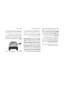
Congratulations on selecting your new Chrysler
Group LLC vehicle. Be assured that it represents precision workmanship, distinctive styling, and high quality - all essentials that are
traditional to our vehicles.
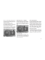
This is a specialized utility vehicle. It can go
places and perform tasks that conventional
passenger cars are not intended. It handles and
maneuvers differently from many passenger
cars both on-road and off-road, so take time to
become familiar with your vehicle.
The two-wheel drive version of this vehicle was
designed for on-road use only. It is not intended
for off-road driving or use in other severe conditions suited for a four-wheel drive vehicle.
Before you start to drive this vehicle, read the
Owner’s Manual and all the Supplements. Be
sure you are familiar with all vehicle controls,
particularly those used for braking, steering,
and transmission and power transfer unit shifting. Learn how your vehicle handles on different
road surfaces. Your driving skills will improve
with experience, but as in driving any vehicle,
take it easy as you begin. When driving off-road
4
or working the vehicle, don’t overload it or
expect it to overcome the forces of nature.
Always observe local laws wherever you drive.
by an authorized dealer or distributor who has
the qualified personnel, special tools and equipment to perform all service.
As with other vehicles of this type, failure to
operate this vehicle correctly may result in loss
of control or a collision. Be sure to read the
“On-Road/ Off-Road Driving Tips” in “Starting
And Operating” for further information.
The manufacturer and its distributors are vitally
interested in your complete satisfaction with this
vehicle. If you encounter a service or warranty
problem which is not resolved to your satisfaction, discuss the matter with your authorized
dealer or distributor’s management.
NOTE:
After reviewing the owner information, it
should be stored in the vehicle for convenient referencing and remain with the vehicle when sold.
Failure to operate this vehicle correctly may
result in loss of control or a collision.
Operating this vehicle at excessive speeds or
while intoxicated may result in loss of control,
collision with other vehicles or objects, going off
the road, or overturning; any of which may lead
to serious injury or death. Also, failure to use
seat belts subjects the driver and passengers to
a greater risk of injury or death.
To keep your vehicle running at its best, have
your vehicle serviced at recommended intervals
Your authorized dealer or distributor will be
happy to assist you with any questions about
your vehicle.
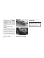
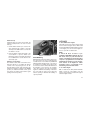
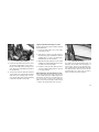
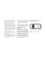
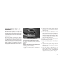
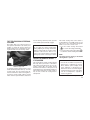
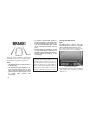
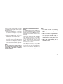
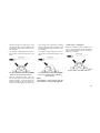
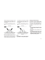
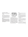
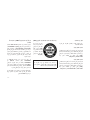
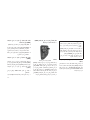
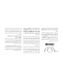
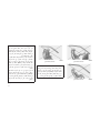
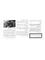
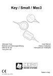
ROLLOVER WARNING
Utility vehicles have a significantly higher rollover rate than other types of vehicles. This
vehicle has a higher ground clearance and a
higher center of gravity than many passenger
cars. It is capable of performing better in a wide
variety of off-road applications. Driven in an
unsafe manner, all vehicles can go out of control. Because of the higher center of gravity, if
this vehicle is out of control it may roll over when
some other vehicles may not.
Do not attempt sharp turns, abrupt maneuvers,
or other unsafe driving actions that can cause
loss of vehicle control. Failure to operate this
vehicle safely may result in a collision, rollover
of the vehicle, and severe or fatal injury. Drive
carefully.
IMPORTANT NOTICE
ALL MATERIAL CONTAINED IN THIS PUBLICATION IS BASED ON THE LATEST INFORMATION AVAILABLE AT TIME OF PUBLICATION APPROVAL. THE RIGHT IS RESERVED
TO PUBLISH REVISIONS AT ANY TIME.
This Owner’s Manual has been prepared with
the assistance of service and engineering specialists to acquaint you with the operation and
maintenance of your new vehicle. It is supplemented by a Warranty Information Booklet and
various customer-oriented documents. You are
urged to read these publications carefully. Following the instructions and recommendations in
this Owner’s Manual will help assure safe and
enjoyable operation of your vehicle.
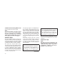
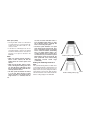
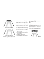
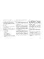
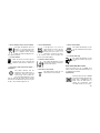
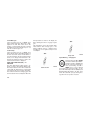
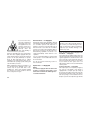
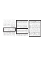
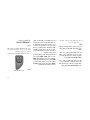
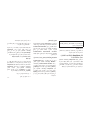
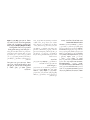
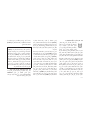
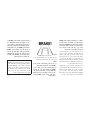
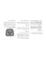
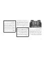
Rollover Warning Label
Failure to use the driver and passenger seat
belts provided is a major cause of severe or
fatal injury. In a rollover crash, an unbelted
person is significantly more likely to die than a
person wearing a seat belt. Always buckle up.
After you have read the Owner’s Manual, it should
be stored in the vehicle for convenient reference
and remain with the vehicle when sold.
The manufacturer reserves the right to make
changes in design and specifications, and/or to
make additions to or improvements in its products without imposing any obligations upon
itself to install them on products previously
manufactured.
The Owner’s Manual illustrates and describes
the features that are standard or available as
extra cost options. Therefore, some of the
equipment and accessories in this publication
may not appear on your vehicle.
NOTE:
Be sure to read the Owner’s Manual first
before driving your vehicle and before attaching or installing parts/accessories or
making other modifications to the vehicle.
In view of the many replacement parts and
accessories from various manufacturers available on the market, the manufacturer cannot be
certain that the driving safety of your vehicle will
not be impaired by the attachment or installation
of such parts. Even if such parts are officiallyapproved (for example, by a general operating
permit for the part or by constructing the part in
an officially approved design), or if an individual
operating permit was issued for the vehicle after
the attachment or installation of such parts, it
cannot be implicitly assumed that the driving
safety of your vehicle is unimpaired. Therefore,
neither experts nor official agencies are liable.
The manufacturer only assumes responsibility
5
when parts, which are expressly authorized or
recommended by the manufacturer, are attached or installed at an authorized dealer. The
same applies when modifications to the original
condition are subsequently made on the manufacturer’s vehicles.
Your warranties do not cover any part that the
manufacturer did not supply. Nor do they cover
the cost of any repairs or adjustments that might
be caused or needed because of the installation
or use of non-manufacturer parts, components,
equipment, materials, or additives. Nor do your
warranties cover the costs of repairing damage
or conditions caused by any changes to your
vehicle that do not comply with the manufacturers specifications.
6
Original MOPAR® parts and accessories and
other products approved by the manufacturer,
including qualified advice, are available at your
authorized dealer.
HOW TO USE THIS MANUAL
When it comes to service, remember that your
authorized dealer knows your vehicle best, has
the factory-trained technicians and genuine
MOPAR® parts, and is interested in your satisfaction.
Since the specification of your vehicle depends
on the items of equipment ordered, certain
descriptions and illustrations may differ from
your vehicle’s equipment.
Copyright © 2014 Chrysler International.
The detailed index at the back of this Owner’s
Manual contains a complete listing of all subjects.
Consult the Table of Contents to determine
which section contains the information you desire.
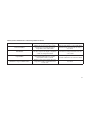
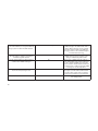
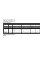
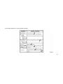
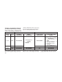
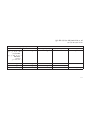
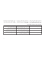
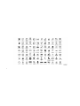
Consult the following table for a description of
the symbols that may be used on your vehicle or
throughout this Owner’s Manual:
7
WARNINGS AND CAUTIONS
VEHICLE MODIFICATIONS/
ALTERATIONS
This Owners Manual contains WARNINGS
against operating procedures that could result
in a collision or bodily injury. It also contains
CAUTIONS against procedures that could result in damage to your vehicle. If you do not
read this entire Owners Manual, you may miss
important information. Observe all Warnings
and Cautions.
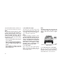
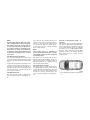
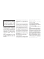
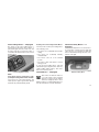
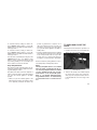
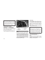
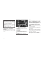
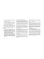
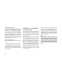
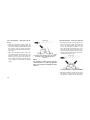
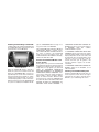
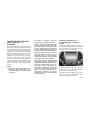
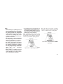
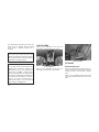
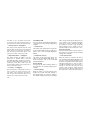
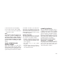
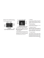
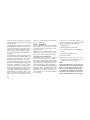
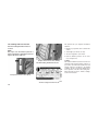
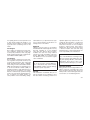
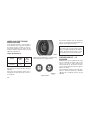
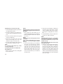
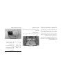
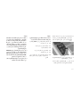
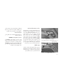
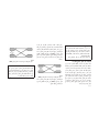
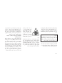
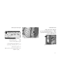
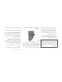
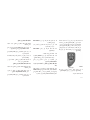
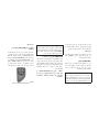
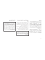
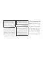
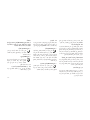
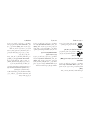
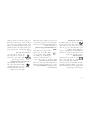
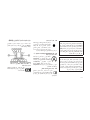
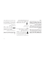
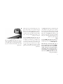
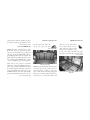
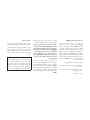
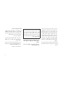
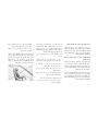
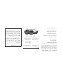
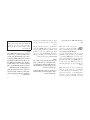
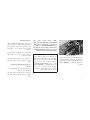
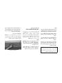
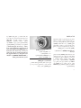
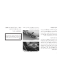
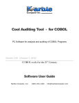
VEHICLE IDENTIFICATION
NUMBER
The Vehicle Identification Number (VIN) is
found on the left front corner of the instrument
panel. The VIN is visible from outside of the
vehicle through the windshield. The VIN number
also is stamped into the right front body, on the
right front seat cross member. With the seat in
the rear most position a flap in the carpet can be
cut open and lifted to reveal the VIN. It also
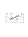
appears on the Automobile Information Disclosure Label affixed to a window on your vehicle,
the vehicle registration, and the title.
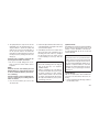
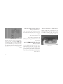
The VIN is also stamped on either right or left
hand side of the engine block.
8
WARNING!
Any modifications or alterations to this vehicle could seriously affect its roadworthiness and safety and may lead to a collision
resulting in serious injury or death.
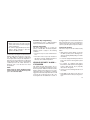
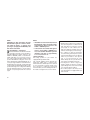
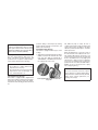
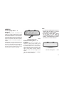
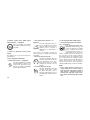
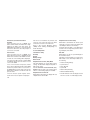
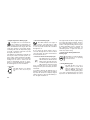
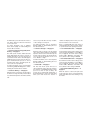
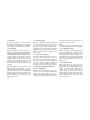
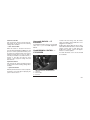
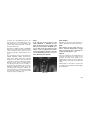
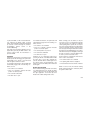
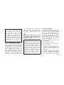
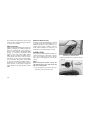
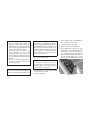
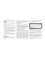
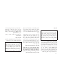
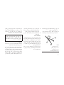
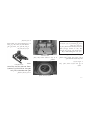
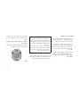
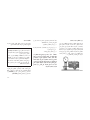
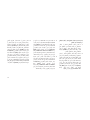
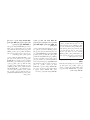
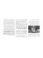
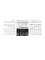
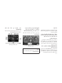
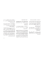
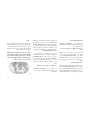
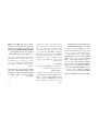
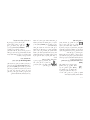
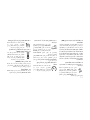
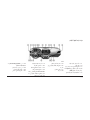
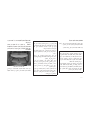
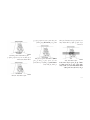
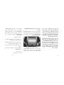
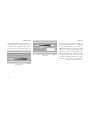
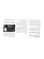
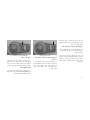
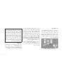
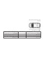
Vehicle Identification Number
Right Front Body VIN Location
NOTE:
It is illegal to remove or alter the VIN.
2
THINGS TO KNOW BEFORE STARTING
YOUR VEHICLE
• A WORD ABOUT YOUR KEYS . . . . . . . . . .
• Ignition Node Module (IGNM) — If Equipped .
• Keyless Ignition Node (KIN) . . . . . . . . . .
• Key Fob — If Equipped . . . . . . . . . . . . .
• Ignition Or Accessory On Message . . . . . .
• STEERING WHEEL LOCK — IF EQUIPPED . .
• To Manually Lock The Steering Wheel . . . .
• To Release The Steering Wheel Lock . . . . .
• SENTRY KEY®. . . . . . . . . . . . . . . . . . . .
• Replacement Keys . . . . . . . . . . . . . . .
• Customer Key Programming . . . . . . . . . .
• General Information . . . . . . . . . . . . . . .
• VEHICLE SECURITY ALARM — IF EQUIPPED
• To Arm The System . . . . . . . . . . . . . . .
• To Disarm The System . . . . . . . . . . . . .
• Security System Manual Override . . . . . . .
• ILLUMINATED ENTRY . . . . . . . . . . . . . . .
• REMOTE KEYLESS ENTRY (RKE) . . . . . . .
.
.
.
.
.
.
.
.
.
.
.
.
.
.
.
.
.
.
.
.
.
.
.
.
.
.
.
.
.
.
.
.
.
.
.
.
.
.
.
.
.
.
.
.
.
.
.
.
.
.
.
.
.
.
.
.
.
.
.
.
.
.
.
.
.
.
.
.
.
.
.
.
.
.
.
.
.
.
.
.
.
.
.
.
.
.
.
.
.
.
.
.
.
.
.
.
.
.
.
.
.
.
.
.
.
.
.
.
.
.
.
.
.
.
.
.
.
.
.
.
.
.
.
.
.
.
.
.
.
.
.
.
.
.
.
.
.
.
.
.
.
.
.
.
.
.
.
.
.
.
.
.
.
.
.
.
.
.
.
.
.
.
.
.
.
.
.
.
.
.
.
.
.
.
.
.
.
.
.
.
.
.
.
.
.
.
.
.
.
.
.
.
.
.
.
.
.
.
.11
.11
.11
.12
.12
.13
.13
.14
.14
.14
.15
.15
.15
.15
.16
.16
.16
.17
9
•
•
•
•
•
•
•
10
• To Unlock The Doors And Liftgate . . . . . . . . . . . . . . . .
• To Lock The Doors And Liftgate . . . . . . . . . . . . . . . . .
• Programming Additional Transmitters . . . . . . . . . . . . .
• Transmitter Battery Replacement . . . . . . . . . . . . . . . .
• General Information . . . . . . . . . . . . . . . . . . . . . . . .
DOOR LOCKS . . . . . . . . . . . . . . . . . . . . . . . . . . . . .
• Manual Door Locks. . . . . . . . . . . . . . . . . . . . . . . . .
• Power Door Locks . . . . . . . . . . . . . . . . . . . . . . . . .
• Child-Protection Door Lock System — Rear Doors . . . . .
KEYLESS ENTER-N-GO™ . . . . . . . . . . . . . . . . . . . . .
WINDOWS . . . . . . . . . . . . . . . . . . . . . . . . . . . . . . .
• Power Windows . . . . . . . . . . . . . . . . . . . . . . . . . .
• Wind Buffeting . . . . . . . . . . . . . . . . . . . . . . . . . . .
LIFTGATE . . . . . . . . . . . . . . . . . . . . . . . . . . . . . . .
• Power Liftgate — If Equipped . . . . . . . . . . . . . . . . . .
OCCUPANT RESTRAINT SYSTEMS . . . . . . . . . . . . . . .
• Important Safety Precautions . . . . . . . . . . . . . . . . . .
• Seat Belt Systems . . . . . . . . . . . . . . . . . . . . . . . . .
• Supplemental Restraint System (SRS) . . . . . . . . . . . . .
• Child Restraints . . . . . . . . . . . . . . . . . . . . . . . . . .
• Transporting Pets . . . . . . . . . . . . . . . . . . . . . . . . .
ENGINE BREAK-IN RECOMMENDATIONS . . . . . . . . . . .
SAFETY TIPS . . . . . . . . . . . . . . . . . . . . . . . . . . . . .
• Transporting Passengers . . . . . . . . . . . . . . . . . . . . .
• Exhaust Gas . . . . . . . . . . . . . . . . . . . . . . . . . . . .
• Safety Checks You Should Make Inside The Vehicle . . . . .
• Periodic Safety Checks You Should Make Outside The Vehicle
.
.
.
.
.
.
.
.
.
.
.
.
.
.
.
.
.
.
.
.
.
.
.
.
.
.
.
.
.
.
.
.
.
.
.
.
.
.
.
.
.
.
.
.
.
.
.
.
.
.
.
.
.
.
.
.
.
.
.
.
.
.
.
.
.
.
.
.
.
.
.
.
.
.
.
.
.
.
.
.
.
.
.
.
.
.
.
.
.
.
.
.
.
.
.
.
.
.
.
.
.
.
.
.
.
.
.
.
.17
.18
.18
.18
.20
.20
.20
.21
.22
.22
.25
.25
.27
.27
.28
.30
.30
.31
.37
.50
.63
.64
.64
.64
.64
.65
.66
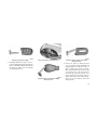
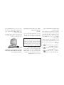
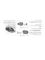
A WORD ABOUT YOUR KEYS
Keyless Ignition Node (KIN)
Your vehicle uses either a key start ignition
system or keyless ignition system. The key start
ignition system consists of a either a Key Fob
with Remote Keyless Entry (RKE) transmitter
and an Ignition Node Module (IGNM). The keyless ignition system consists of a Key Fob with
Remote Keyless Entry (RKE) transmitter and a
Keyless Ignition Node (KIN).
This feature allows the driver to operate the
ignition switch with the push of a button, as long
as the Remote Keyless Entry (RKE) transmitter
is in the passenger compartment.
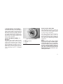
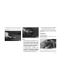
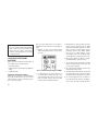
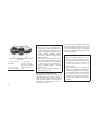
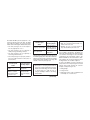
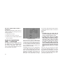
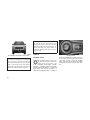
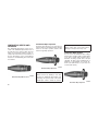
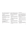
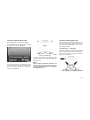
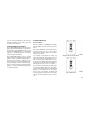
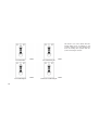
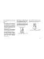
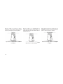
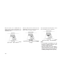
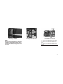
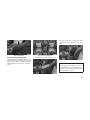
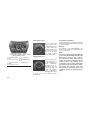
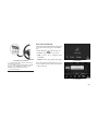
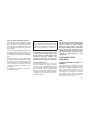
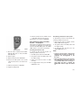
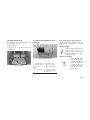
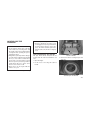
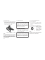
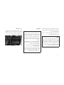
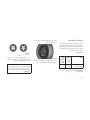
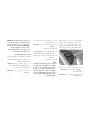
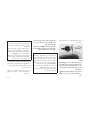
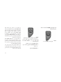
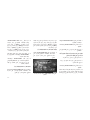
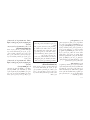
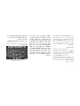
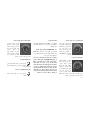
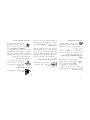
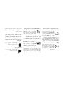
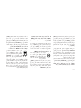
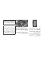
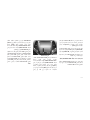
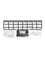
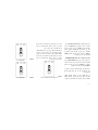
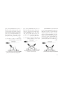
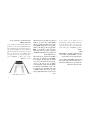
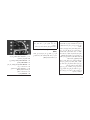
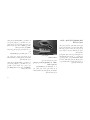
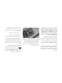
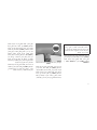
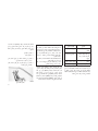
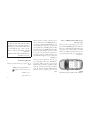
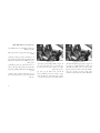
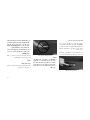
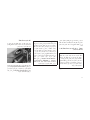
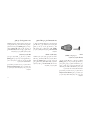
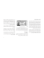
Ignition Node Module (IGNM) — If
Equipped
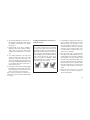
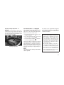
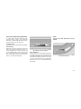
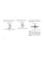
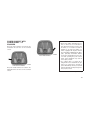
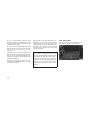
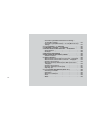
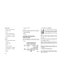
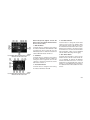
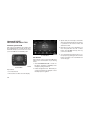
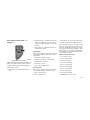
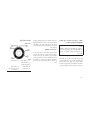
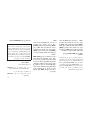
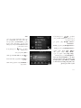
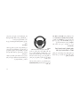
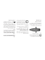
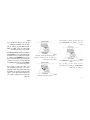
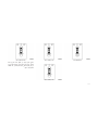
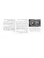
The Ignition Node Module (IGNM) operates
similar to an ignition switch. It has four operating
positions, three with detents and one that is
spring-loaded. The detent positions are OFF,
ACC, and ON/RUN. The START position is a
spring-loaded momentary contact position.
When released from the START position, the
switch automatically returns to the ON/RUN
position.
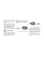
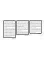
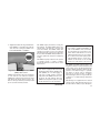
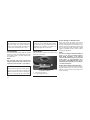
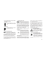
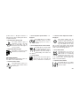
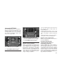
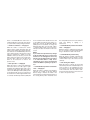
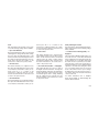
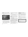
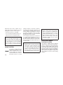
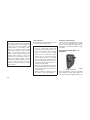
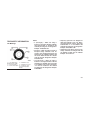
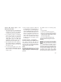
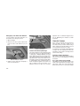
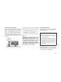
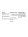
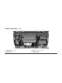
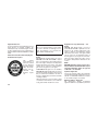
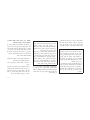
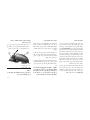
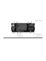
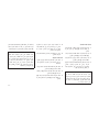
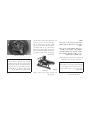
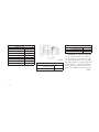
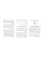
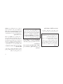
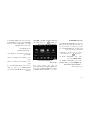
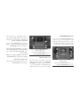
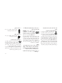
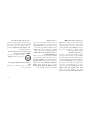
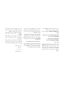
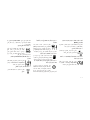
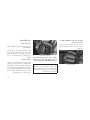
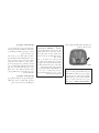
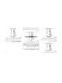
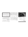
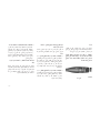
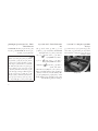
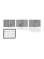
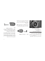
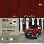
Ignition Node Module (IGNM)
1
2
3
4
— OFF
— ACC (ACCESSORY)
— ON/RUN
— START
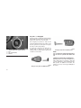
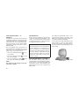
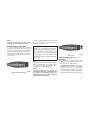
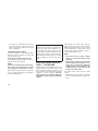
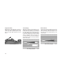
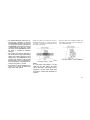
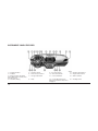
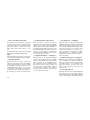
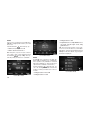
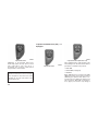
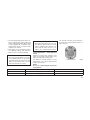
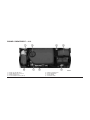
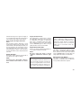
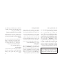
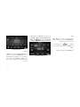
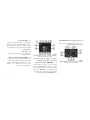
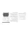
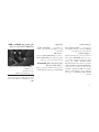
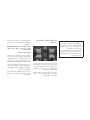
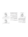
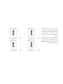
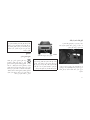
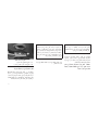
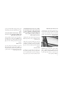
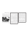
The Keyless Ignition Node (KIN System) has
four operating positions, three of which are
labeled and will illuminate when in position. The
three positions are: OFF, ACC, and ON/RUN.
The fourth position is START. During start, RUN
will illuminate.
NOTE:
In case the ignition switch does not change
with the push of a button, the RKE transmitter (Key Fob) may have a low or dead battery. In this situation a back up method can
be used to operate the ignition switch. Put
the nose side (side opposite of the emergency key) of the Key Fob against the ENGINE START/STOP button and push to operate the ignition switch.
11
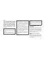
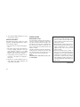
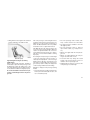
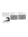
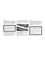
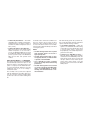
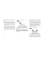
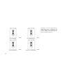
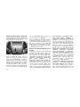
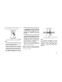
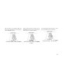
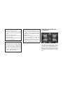
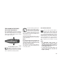
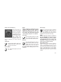
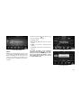
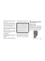
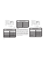
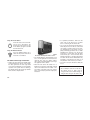
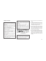
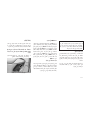
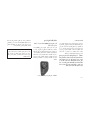
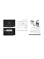
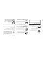
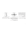
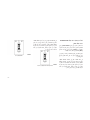
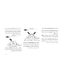
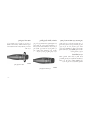
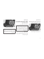
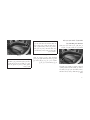
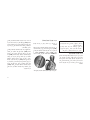
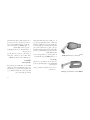
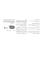
Key Fob — If Equipped
The Key Fob also contains the Remote Keyless
Entry (RKE) transmitter and an emergency key,
which stores in the rear of the Key Fob.
The emergency key allows for entry into the
vehicle should the battery in the vehicle or the
Key Fob go dead. You can keep the emergency
key with you when valet parking.
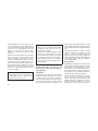
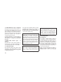
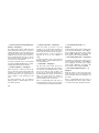
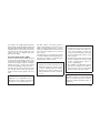
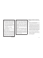
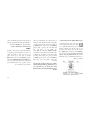
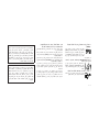
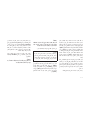
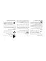
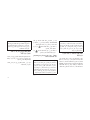
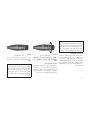
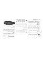
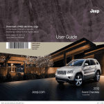
Keyless Ignition Node (KIN System)
1 — OFF
2 — ACC (ACCESSORY)
3 — ON/RUN
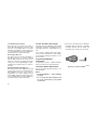
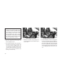
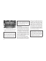
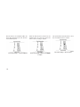
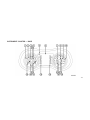
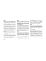
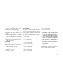
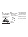
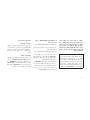
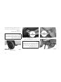
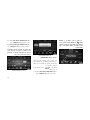
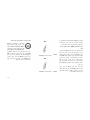
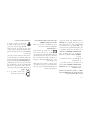
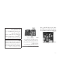
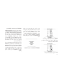
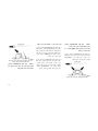
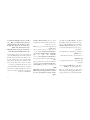
To remove the emergency key, slide the mechanical latch on the face of the Key Fob
sideways with your thumb and then pull the key
out with your other hand.
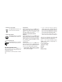
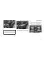
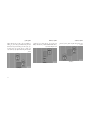
Emergency Key Removal (KIN System)
NOTE:
You can insert the double-sided emergency
key into the lock cylinders with either side
up.
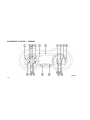
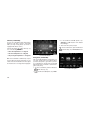
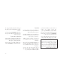
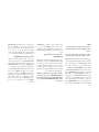
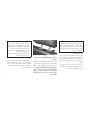
Ignition Or Accessory On Message
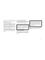
Emergency Key Removal (IGNM System)
12
Opening the driver’s door when the ignition is in
ACC or ON (engine not running), a chime will
sound to remind you to place the ignition in the
OFF position. In addition to the chime, the
ignition or accessory on message will display in
the cluster.
NOTE:
The power window switches, radio, power
sunroof (if equipped), and power outlets will
remain active for up to 10 minutes after the
ignition is cycled to the OFF position. Opening either front door will cancel this feature.
The time for this feature is programmable.
Refer to “Uconnect® Settings” in “Understanding Your Instrument Panel” for further
information.
WARNING!
• When leaving the vehicle, always remove
the Key Fob from the vehicle and lock your
vehicle.
• Never leave children alone in a vehicle, or
with access to an unlocked vehicle.
(Continued)
WARNING! (Continued)
• Allowing children to be in a vehicle unattended is dangerous for a number of reasons. A child or others could be seriously
or fatally injured. Children should be
warned not to touch the parking brake,
brake pedal or the gear selector.
• Do not leave the Key Fob in or near the
vehicle, or in a location accessible to children, and do not leave the ignition of a
vehicle equipped with Keyless Enter-NGo™ in the ACC or ON/RUN mode. A child
could operate power windows, other controls, or move the vehicle.
• Do not leave children or animals inside
parked vehicles in hot weather. Interior
heat build-up may cause serious injury or
death.
CAUTION!
An unlocked car is an invitation to thieves.
Always remove key from the ignition and lock
all doors when leaving the vehicle unattended.
STEERING WHEEL LOCK — IF
EQUIPPED
Your vehicle may be equipped with a passive
electronic steering wheel lock. This lock prevents steering the vehicle with the ignition OFF.
The steering wheel lock releases with the ignition On. If the lock does not disengage and the
vehicle does not start, turn the wheel to the left
and right to disengage the lock.
To Manually Lock The Steering
Wheel
With the engine running, rotate the steering
wheel one-quarter revolution in either direction,
turn off the engine and remove the key. Turn the
steering wheel slightly in either direction until
the lock engages.
13
To Release The Steering Wheel Lock
Cycle the ignition and start the engine.
NOTE:
If you turned the wheel to the right to engage
the lock, you must turn the wheel slightly to
the right to disengage it. If you turned the
wheel to the left to engage the lock, turn the
wheel slightly to the left to disengage it.
SENTRY KEY®
The Sentry Key® Immobilizer system prevents
unauthorized vehicle operation by disabling the
engine. The system does not need to be armed
or activated. Operation is automatic, regardless
of whether the vehicle is locked or unlocked.
The system uses a Key Fob with a factorymated Remote Keyless Entry (RKE) transmitter,
a Keyless Ignition Node (KIN) and a RF receiver
to prevent unauthorized vehicle operation.
Therefore, only Key Fobs that are programmed
to the vehicle can be used to start and operate
the vehicle. The system will not allow the engine
to crank if an invalid Key Fob.
14
After placing the ignition to the ON/RUN position, the Vehicle Security Light will turn on for
three seconds for a bulb check. If the light
remains on after the bulb check, it indicates that
there is a problem with the system. In addition,
if the light begins to flash after the bulb check, it
indicates that someone used an invalid Key Fob
to start the engine. Either of these conditions
will result in the engine being shut off after two
seconds.
If the Vehicle Security Light turns on during
normal vehicle operation (vehicle running for
longer than 10 seconds), it indicates that there
is a fault in the system. Should this occur, have
the vehicle serviced as soon as possible by an
authorized dealer.
CAUTION!
• Do not make modifications or alterations to
the immobilizer system. Modifications or
alterations to the immobilization system
may result in a loss of security protection.
(Continued)
CAUTION! (Continued)
• The Sentry Key® Immobilizer system is
not compatible with some aftermarket remote starting systems. Use of these systems may result in vehicle starting problems and loss of security protection.
All of the Key Fobs provided with your new
vehicle have been programmed to the vehicle
electronics.
Replacement Keys
NOTE:
Only Key Fobs that are programmed to the
vehicle electronics can be used to start and
operate the vehicle. Once a Key Fob is
programmed to a vehicle, it cannot be programmed to any other vehicle.
CAUTION!
• Always remove the Key Fobs from the
vehicle and lock all doors when leaving the
vehicle unattended.
• For vehicles equipped with Keyless EnterN-Go™, always remember to place the
ignition in the OFF position.
At the time of purchase, the original owner is
provided with a four-digit Personal Identification
Number (PIN). Keep the PIN in a secure location. This number is required for authorized
dealer replacement of Key Fobs. Duplication of
Key Fobs may be performed at an authorized
dealer. This procedure consists of programming
a blank Key Fob to the vehicle electronics. A
blank Key Fob is one that has never been
programmed.
NOTE:
When having the Sentry Key® Immobilizer
System serviced, bring all vehicle keys with
you to an authorized dealer.
Customer Key Programming
Programming Key Fobs or RKE transmitters
may be performed at an authorized dealer.
General Information
The Sentry Key® operates on a carrier frequency of 433.92 MHz. The Sentry Key® Immobilizer system is subject to the following
conditions:
• This device may not cause harmful interference.
• This device must accept any interference
that may be received, including interference
that may cause undesired operation.
VEHICLE SECURITY ALARM —
IF EQUIPPED
This Vehicle Security Alarm monitors the vehicle doors, hood, liftgate, and ignition for unauthorized operation. While the Vehicle Security
Alarm is armed, interior switches for door locks
and liftgate release are disabled. If something
triggers the Vehicle Security Alarm the horn will
sound for 29 seconds and turn off all of the
visual signals after an additional 31 seconds. If
the triggering device is not deactivated, the horn
will sound again after a five second delay for
another 29 seconds. If the trigger remains present, this cycle will repeat for up to five minutes.
To Arm The System
Follow these steps to arm the Vehicle Security
Alarm:
1. Make sure the vehicles ignition is cycled to
the “OFF” position (refer to "Starting Procedures" in "Starting And Operating" for further
information).
• For vehicles equipped with Keyless Enter-NGo™, make sure the vehicle ignition system
is OFF.
• For vehicles not equipped with Keyless
Enter-N-Go™, make sure the vehicle ignition
system is OFF and the key is physically
removed from the ignition.
2. Perform one of the following methods to lock
the vehicle:
• Push LOCK on the interior power door lock
switch with the driver and/or passenger door
open.
15
• Push the LOCK button on the exterior Passive Entry Door Handle with a valid Key Fob
available in the same exterior zone (refer to
"Keyless Enter-N-Go™" in "Things To Know
Before Starting Your Vehicle" for further
information).
• Push the LOCK button on the Remote Keyless Entry (RKE) transmitter.
3. If any doors are open, close them.
To Disarm The System
The Vehicle Security Alarm can be disarmed
using any of the following methods:
• Press the UNLOCK button on the Remote
Keyless Entry (RKE) transmitter.
• Grasp the Passive Entry Unlock Door Handle
with a valid Key Fob available in the same
exterior zone (if equipped), refer to "Keyless
Enter-N-Go™ " in "Things To Know Before
Starting Your Vehicle" for further information.
• Cycle the vehicle ignition system out of the
OFF position.
• For vehicles equipped with Keyless EnterN-Go™ , press the Keyless Enter-N-Go™
16
Start/Stop button (requires at least one
valid Key Fob in the vehicle).
• For vehicles not equipped with Keyless
Enter-N-Go™ , insert a valid key into the
ignition switch and turn the key to the ON
position.
NOTE:
• The driver’s door key cylinder and the
liftgate button on the RKE transmitter
cannot arm or disarm the Vehicle Security
Alarm.
arming sequences has occurred, the Vehicle
Security Alarm will arm regardless of whether
you are in the vehicle or not. If you remain in the
vehicle and open a door, the alarm will sound. If
this occurs, disarm the Vehicle Security Alarm.
If the Vehicle Security Alarm is armed and the
battery becomes disconnected, the Vehicle Security Alarm will remain armed when the battery
is reconnected; the exterior lights will flash, the
horn will sound. If this occurs, disarm the Vehicle Security Alarm.
• The Vehicle Security Alarm remains
armed during power liftgate entry. Pressing the liftgate button will not disarm the
Vehicle Security Alarm. If someone enters
the vehicle through the liftgate and opens
any door the alarm will sound.
Security System Manual Override
• When the Vehicle Security Alarm is
armed, the interior power door lock
switches will not unlock the doors.
The courtesy lights will turn on when you use
the Remote Keyless Entry (RKE) transmitter to
unlock the doors or open any door.
The Vehicle Security Alarm is designed to protect your vehicle; however, you can create
conditions where the system will give you a
false alarm. If one of the previously described
This feature also turns on the approach lighting
in the outside mirrors — if equipped. Refer to
“Mirrors” in “Understanding The Features Of
Your Vehicle” for further information.
The Vehicle Security Alarm will not arm if you
lock the doors using the manual door lock
plunger.
ILLUMINATED ENTRY
The lights will fade to off after approximately 30
seconds or they will immediately fade to off
once the ignition switch is turned to ON/RUN
from the OFF position.
NOTE:
NOTE:
Driving at speeds 5 mph (8 km/h) and above
disables the system from responding to all
RKE transmitter buttons for all RKE transmitters.
• The front courtesy overhead console and
door courtesy lights do not turn on if the
dimmer control is in the “Dome defeat”
position (extreme bottom position).
• The Illuminated Entry system will not operate if the dimmer control is in the
“Dome defeat” position (extreme bottom
position).
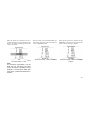
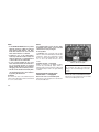
REMOTE KEYLESS ENTRY
(RKE)
The RKE system allows you to lock or unlock
the doors and open the power liftgate from
distances up to approximately 66 ft (20 m) using
a hand-held Key Fob with RKE transmitter. The
RKE transmitter does not need to be pointed at
the vehicle to activate the system.
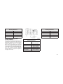
Emergency Key Removal (IGNM)
To Unlock The Doors And Liftgate
Emergency Key Removal (KIN)
Push and release the UNLOCK button on the
RKE transmitter once to unlock the driver’s door
or twice within five seconds to unlock all doors
and liftgate. The turn signal lights will flash to
acknowledge the unlock signal. The illuminated
entry system will also turn on.
If the vehicle is equipped with Passive Entry,
refer to “Keyless Enter-N-Go™” in “Things To
Know Before Starting Your Vehicle” for further
information.
17
1st Push Of Key Fob Unlocks
This feature lets you program the system to
unlock either the driver’s door or all doors on the
first push of the UNLOCK button on the RKE
transmitter. To change the current setting, refer
to “Uconnect® Settings” in “Understanding Your
Instrument Panel” for further information.
Flash Lamps With Lock
This feature will cause the turn signal lights to
flash when the doors are locked or unlocked
with the RKE transmitter. This feature can be
turned on or turned off. To change the current
setting, refer to “Uconnect® Settings” in “Understanding Your Instrument Panel” for further information.
Headlight Illumination On Approach
This feature activates the headlights for up to 90
seconds when the doors are unlocked with the
RKE transmitter. The time for this feature is
programmable on vehicles equipped through
Uconnect®. To change the current setting, refer
to “Uconnect® Settings” in “Understanding Your
Instrument Panel” for further information.
18
To Lock The Doors And Liftgate
Push and release the LOCK button on the RKE
transmitter to lock all doors and liftgate. The turn
signal lights will flash to acknowledge the signal.
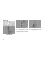
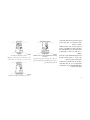
1. Remove the emergency key by sliding the
mechanical latch on the back of the RKE
transmitter sideways with your thumb and
then pull the key out with your other hand.
If the vehicle is equipped with Passive Entry,
refer to “Keyless Enter-N-Go™” under “Things
To Know Before Starting Your Vehicle” for further information.
Programming Additional
Transmitters
Programming Key Fobs or RKE transmitters
may be performed at an authorized dealer.
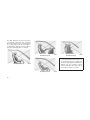
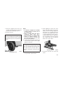
Transmitter Battery Replacement
The recommended replacement battery is one
CR2032 battery.
NOTE:
• Perchlorate Material — special handling
may apply.
• Do not touch the battery terminals that
are on the back housing or the printed
circuit board.
Emergency Key Removal (IGNM)
Emergency Key Removal (KIN)
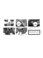
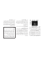
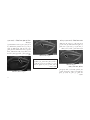
Remove Screw From Transmitter Case
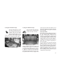
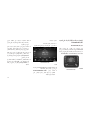
2. Separating RKE halves requires screw removal (if equipped) and gently prying the two
halves of the RKE transmitter apart with the
emergency key. Make sure not to damage
the seal during removal.
Separating Ignition Node Module (IGNM)
Transmitter Case
Separating Keyless Ignition Node (KIN)
Transmitter Case
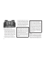
3. Remove the battery by turning the back
cover over (battery facing downward) and
tapping it lightly on a solid surface such as a
table or similar, then replace the battery.
When replacing the battery, match the + sign
on the battery to the + sign on the inside of
the battery clip, located on the back cover.
Avoid touching the new battery with your
fingers. Skin oils may cause battery deterioration. If you touch a battery, clean it with
rubbing alcohol.
19
4. To assemble the RKE transmitter case, snap
the two halves together.
General Information
Transmitter and receivers operate on a carrier
frequency of 433.92 MHz. Operation is subject
to the following conditions:
• This device may not cause harmful interference.
• This device must accept any interference
received, including interference that may
cause undesired operation. If your RKE
transmitter fails to operate from a normal
distance, check for these two conditions:
1. A weak battery in the transmitter. The expected life of the battery is a minimum of
three years.
2. Closeness to a radio transmitter such as a
radio station tower, airport transmitter, and
some mobile or CB radios.
20
DOOR LOCKS
Manual Door Locks
To lock each door, rotate the door lock knob on
each door trim panel forward. To unlock the
front doors, pull the inside door handle to the
first detent or rotate the door lock button until
the red indicator is visible. To unlock the rear
doors, rotate the door lock button until the red
indicator is visible.
If the door lock button is locked (no red indicator
visible) when you shut the door, the door will
lock. Therefore, make sure the Key Fob is not
inside the vehicle before closing the door.
NOTE:
The manual door locks will not lock or unlock the liftgate.
WARNING!
• For personal security and safety in the
event of a collision, lock the vehicle doors
before you drive as well as when you park
and leave the vehicle.
• When leaving the vehicle, always remove
the Key Fob from the vehicle and lock your
vehicle. Unsupervised use of vehicle
equipment may cause severe personal
injuries or death.
• Never leave children alone in a vehicle, or
with access to an unlocked vehicle. Allowing children to be in a vehicle unattended
is dangerous for a number of reasons. A
child or others could be seriously or fatally
injured. Children should be warned not to
touch the parking brake, brake pedal or the
gear selector.
(Continued)
and the ignition is in the ACC or ON/RUN
position, a chime will sound as a reminder to
remove the Key Fob.
WARNING! (Continued)
• Do not leave the Key Fob in or near the
vehicle, or in a location accessible to children, and do not leave the ignition of a
vehicle equipped with Keyless Enter-NGo™ in the ACC or ON/RUN mode. A child
could operate power windows, other controls, or move the vehicle.
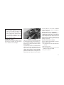
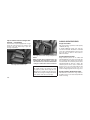
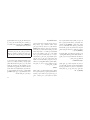
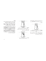
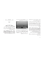
Power Door Locks
A power door lock switch is located on each of
the front door trim panels. Use this switch to
lock or unlock the doors and liftgate.
Power Door Lock Switch
The doors can also be locked and unlocked with
the Keyless Enter-N-Go™ (Passive Entry) system. For further information, refer to “Keyless
Enter-N-Go™” in “Things To Know Before Starting Your Vehicle”.
If you push the power door lock switch while the
ignition is in the ACC or ON/RUN position, and
any front door is open, the power locks will not
operate. This prevents you from accidentally
locking the Key Fob in the vehicle. Place the
ignition to the OFF position or closing the door
will allow the locks to operate. If a door is open,
Automatic Door Locks — If Equipped
The auto door lock feature default condition is
enabled. When enabled, the door locks will lock
automatically when the vehicle’s speed exceeds 15 mph (24 km/h). The auto door lock
feature can be enabled or disabled by your
authorized dealer or through the Uconnect®
Settings in your radio.
Automatic Unlock Doors On Exit
The doors will unlock automatically on vehicles
with power door locks if:
1. The Automatic Unlock Doors On Exit feature
is enabled.
2. All doors are closed.
3. The transmission shift lever was not in
PARK, then is placed in PARK.
4. Any door is opened.
21
Automatic Unlock Doors On Exit
Programming
To change the current setting, refer to
“Uconnect® Settings” in “Understanding Your
Instrument Panel” for further information.
• For emergency exit with the system engaged, move the lock knob up (unlocked
position), roll down the window, and open
the door with the outside door handle.
NOTE:
Use the Automatic Unlock Doors On Exit
feature in accordance with local laws.
WARNING!
Avoid trapping anyone in a vehicle in a
collision. Remember that the rear doors can
only be opened from the outside when the
Child-Protection locks are engaged.
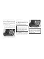
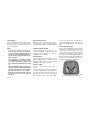
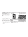
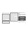
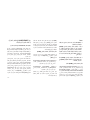
Child-Protection Door Lock System
— Rear Doors
To provide a safer environment for small children riding in the rear seats, the rear doors are
equipped with a Child-Protection Door Lock
system.
To use the system, open each rear door, use a
flat blade screwdriver (or ignition key) and rotate
the dial to the LOCK or UNLOCK position.
When the system on a door is engaged, that
door can only be opened by using the outside
door handle even if the inside door lock is in the
unlocked position.
22
Child-Protection Door Lock Function
NOTE:
• When the child lock system is engaged,
the door can be opened only by using the
outside door handle even though the inside door lock is in the unlocked position.
• After disengaging the Child-Protection
Door Lock system, always test the door
from the inside to make certain it is in the
desired position.
• After engaging the Child-Protection Door
Lock system, always test the door from
the inside to make certain it is in the
desired position.
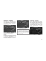
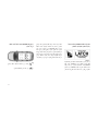
KEYLESS ENTER-N-GO™
The Passive Entry system is an enhancement
to the vehicle’s Remote Keyless Entry (RKE)
system and a feature of Keyless Enter-N-Go™.
This feature allows you to lock and unlock the
vehicle’s door(s) without having to push the
RKE transmitter lock or unlock buttons.
NOTE:
• Passive Entry may be programmed ON/
OFF; refer to “Uconnect® Settings” in
“Understanding Your Instrument Panel”
for further information.
• If wearing gloves on your hands, or if it has
been raining on the Passive Entry door
handle, the unlock sensitivity can be affected, resulting in a slower response time.
• If the vehicle is unlocked by the Passive
Entry Door Handle and no door goes ajar
within 60 seconds, the vehicle will re-lock
and if equipped will arm the security alarm.
To Unlock From The Driver’s Side
With a valid Passive Entry RKE transmitter
within 5 ft (1.5 m) of the driver’s door handle,
grab the front driver door handle to unlock the
driver’s door automatically.
NOTE:
If “Unlock All Doors 1st Press” is programmed all doors will unlock when you
grab hold of the front driver’s door handle.
To select between “Unlock Driver Door 1st
Press” and “Unlock All Doors 1st Press”,
refer to “Uconnect® Settings” in “Understanding Your Instrument Panel” for further
information.
To Unlock From The Passenger Side
With a valid Passive Entry RKE transmitter
within 5 ft (1.5 m) of the passenger door handle,
grab the front passenger door handle to unlock
all four doors and the liftgate automatically.
NOTE:
All doors will unlock when the front passenger door handle is grabbed regardless of the
driver’s door unlock preference setting
(“Unlock Driver Door 1st Press” or “Unlock
All Doors 1st Press”).
Grab The Door Handle To Unlock
Preventing Inadvertent Locking Of Passive
Entry RKE Transmitter In Vehicle (FOBIKSafe)
To minimize the possibility of unintentionally
locking a Passive Entry RKE transmitter inside
your vehicle, the Passive Entry system is
equipped with an automatic door unlock feature
which will function if the ignition switch is in the
OFF position.
FOBIK-Safe only executes in vehicles with passive entry. There are three situations that trigger
a FOBIK-Safe search in any passive entry
vehicle:
1. A lock request is made by a valid Passive
Entry RKE transmitter while a door is ajar.
2. A lock request is made by the Passive Entry
door handle while a door is ajar.
3. A lock request is made by the door panel
switch while the door is ajar.
When any of these situations occur, after all ajar
doors are shut, the FOBIK-Safe search will be
executed. If it finds a Passive Entry RKE transmitter inside the car and it does not find any
23
Passive Entry RKE transmitters outside the car,
then the car will unlock and alert the customer.
NOTE:
The vehicle will only unlock the doors when
a valid Passive Entry RKE transmitter is
detected inside the vehicle, and no valid
Passive Entry RKE transmitter is detected
outside the vehicle. The vehicle will not
unlock the doors when any of the following
conditions are true:
• The doors are manually locked using the
door lock knobs.
• There is a valid Passive Entry RKE transmitter outside the vehicle and within 5 ft
(1.5 m) of either Passive Entry door
handle.
• Three attempts are made to lock the
doors using the door panel switch and
then close the doors
24
To Unlock/Enter The Liftgate
The liftgate passive entry unlock feature is built
into the electronic liftgate release. With a valid
Passive Entry RKE transmitter within 3 ft (1.0 m)
of the liftgate, push the electronic liftgate release to open with one fluid motion.
NOTE:
If “Unlock All Doors 1st Press” is programmed in EVIC/DID if equipped, all doors
will unlock when you push the electronic
release on the liftgate. If ⴖUnlock Driver Door
1st Pressⴖ is programmed in Uconnect®, the
liftgate will unlock when you push the electronic release on the liftgate For further
information, refer to “Uconnect®” in “Understanding Your Instrument Panel”.
To Lock The Liftgate
With a valid Passive Entry RKE transmitter
within 3 ft (1.0 m) of the liftgate, push the
passive entry lock button located to the right of
electronic liftgate release.
NOTE:
The liftgate passive entry lock button will
only lock the liftgate, the liftgate unlock
feature is built into the electronic liftgate
release.
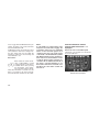
Electronic Liftgate Release/Liftgate Passive
Entry Location
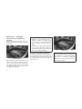
To Lock The Vehicle’s Doors And Liftgate
With one of the vehicle’s Passive Entry RKE
transmitters within 5 ft (1.5 m) of the driver or
passenger front door handles, push the door
handle LOCK button to lock all four doors.
• The Passive Entry system will not operate
if the RKE transmitter battery is dead.
Do NOT grab the door handle, when pushing
the door handle lock button. This could unlock
the door(s).
The vehicle doors can also be locked by using
the lock button located on the vehicle’s interior
door panel.
WINDOWS
Power Windows
DO NOT Grab The Door Handle When Locking
The window controls on the driver’s door control
all the door windows.
NOTE:
Push The Door Handle Button To Lock
• After pushing the door handle button, you
must wait two seconds before you can
lock or unlock the doors, using either
Passive Entry door handle. This is done
to allow you to check if the vehicle is
locked by pulling the door handle, without
the vehicle reacting and unlocking.
• If Passive Entry is disabled using
Uconnect® System, the key protection
described in ⴖPreventing Inadvertent
Locking of Passive Entry RKE Transmitter
in Vehicleⴖ remains active/functional.
Power Window Switches
There are single window controls on each passenger door trim panel, which operate the pas25
senger door windows. The window controls will
operate only when the ignition is in the ACC or
ON/RUN position.
NOTE:
For vehicles equipped with the Uconnect®,
the power window switches will remain active for up to 10 minutes after the ignition is
cycled to the OFF position. Opening either
front door will cancel this feature. The time
is programmable. Refer to “Uconnect® Settings” in “Understanding Your Instrument
Panel” for further information.
WARNING!
Never leave children unattended in a vehicle,
and do not let children play with power
windows. Do not leave the Key Fob in or
near the vehicle, or in a location accessible
to children, and do not leave the ignition of a
vehicle equipped with Keyless Enter-N-Go™
in the ACC or ON/RUN mode. Occupants,
particularly unattended children, can be(Continued)
26
WARNING! (Continued)
come entrapped by the windows while operating the power window switches. Such entrapment may result in serious injury or
death.
AUTO-Down Feature
The driver door power window switch and some
model passenger door power window switches
have an AUTO-down feature. Push the window
switch to the second detent, release, and the
window will go down automatically.
To stop the window from going all the way up
during the AUTO operation, push down on the
switch briefly.
To close the window part way, lift the window
switch to the first detent and release it when you
want the window to stop.
NOTE:
• If the window runs into any obstacle during auto-closure, it will reverse direction
and then go back down. Remove the obstacle and use the window switch again to
close the window.
To stop the window from going all the way down
during the AUTO-down operation, pull up on the
switch briefly.
• Any impact due to rough road conditions
may trigger the auto-reverse function unexpectedly during auto-closure. If this
happens, pull the switch lightly to the first
detent and hold to close the window
manually.
AUTO-Up Feature With Anti-Pinch
Protection
Lift the window switch to the second detent,
release, and the window will go up automatically.
WARNING!
There is no anti-pinch protection when the
window is almost closed. Be sure to clear all
objects from the window before closing.
To open the window part way, push the window
switch to the first detent and release it when you
want the window to stop.
Reset Auto-Up
Should the Auto Up feature stop working, the
window probably needs to be reset. To reset
Auto Up:
LIFTGATE
To Unlock/Enter The Liftgate
The liftgate passive entry unlock feature is built
into the electronic liftgate release. With a valid
Passive Entry RKE transmitter within 3 ft (1.0 m)
of the liftgate, press the electronic liftgate release to open with one fluid motion.
1. Pull the window switch up to close the window completely and continue to hold the
switch up for an additional two seconds after
the window is closed.
2. Push the window switch down firmly to the
second detent to open the window completely and continue to hold the switch down
for an additional two seconds after the window is fully open.
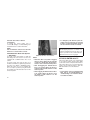
Window Lockout Switch
The window lockout switch on the driver’s door
trim panel allows you to disable the window
controls on the rear passenger doors. To disable the window controls, push and release the
window lockout button (setting it in the DOWN
position). To enable the window controls, push
and release the window lockout button again
(setting it in the UP position).
Window Lockout Switch
Wind Buffeting
Wind buffeting can be described as the perception of pressure on the ears or a helicopter-type
sound in the ears. Your vehicle may exhibit wind
buffeting with the windows down, or the sunroof
in certain open or partially open positions. This
is a normal occurrence and can be minimized. If
the buffeting occurs with the rear windows
open, then open the front and rear windows
together to minimize the buffeting. If the buffeting occurs with the sunroof open, adjust the
sunroof opening to minimize the buffeting or
open any window.
NOTE:
If “Unlock All Doors 1st Press” is programmed in EVIC/DID if equipped, all doors
will unlock when you push the electronic
release on the liftgate. If ⴖUnlock Driver Door
1st pressⴖ is programmed in Uconnect®, the
liftgate will unlock when you press the electronic release on the liftgate For further
information, refer to “Uconnect®” in “Understanding Your Instrument Panel”.
To Lock The Liftgate
With a valid Passive Entry RKE transmitter
within 3 ft (1.0 m) of the liftgate, press the
passive entry lock button located to the right of
electronic liftgate release.
27
NOTE:
The liftgate passive entry lock button will
only lock the liftgate, the liftgate unlock
feature is built into the electronic liftgate
release.
NOTE:
Use the power door LOCK switch on either
front door trim panel or the Remote Keyless
Entry (RKE) transmitter to lock and unlock
the liftgate. The manual door locks on the
doors and the driver’s door lock cylinder will
not lock and unlock the liftgate.
WARNING!
Driving with the liftgate open can allow poisonous exhaust gases into your vehicle. You
and your passengers could be injured by
these fumes. Keep the liftgate closed when
you are operating the vehicle.
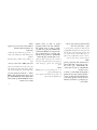
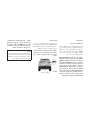
Liftgate Entry
Power Liftgate — If Equipped
The power liftgate may be opened
by pushing the electronic liftgate
release (refer to Keyless Enter-NGo™ located in Things To Know
Before Starting) or by pushing the
LIFTGATE button on the Remote
Keyless Entry (RKE) transmitter. Push the LIFT-
28
GATE button on the RKE transmitter twice
within five seconds, to open the power liftgate.
Once the liftgate is open, pushing the button
twice within five seconds a second time will
close the liftgate.
The power liftgate may also be opened or
closed by pushing the LIFTGATE button located
on the left side of the steering wheel on the
instrument panel, or closed by pushing the
LIFTGATE button located on left rear trim panel,
near the liftgate opening. Push the LIFTGATE
button located on left rear trim panel once will
close the liftgate only, this button cannot be
used to open the liftgate.
When the LIFTGATE button on the RKE transmitter is pushed two times, the turn signals will
flash twice to signal that the liftgate is opening
or closing (if Flash Lamps with Lock is enabled
in the Uconnect® settings) and the liftgate
chime will be audible. For further information,
refer to "Uconnect®" in "Understanding Your
Instrument Panel".
NOTE:
• In the event of a power malfunction to the
liftgate, an emergency liftgate latch release can be used to open the liftgate. The
emergency liftgate latch release can be
accessed through a snap-in cover located
on the liftgate trim panel.
• If liftgate is left open for an extended
period of time, the liftgate may need to be
closed manually to reset power liftgate
functionality.
WARNING!
During power operation, personal injury or
cargo damage may occur. Ensure the liftgate
travel path is clear. Make sure the liftgate is
closed and latched before driving away.
NOTE:
• The power liftgate buttons will not operate if the vehicle is in gear or the vehicle
speed is above 0 mph (0 km/h).
• The power liftgate will not operate in temperatures below −22°F (−30°C) or temperatures above 150°F (65°C). Be sure to
remove any buildup of snow or ice from
the liftgate before pushing any of the
power liftgate switches.
• If anything obstructs the power liftgate
while it is closing or opening, the liftgate
will automatically reverse to the closed or
open position, provided it meets sufficient resistance.
• There are also pinch sensors attached to
the side of the liftgate. Light pressure
anywhere along these strips will cause
the liftgate to return to the open position.
• If the electronic liftgate release is pushed
while the power liftgate is opening, the
liftgate motor will disengage to allow
manual operation.
• If the power liftgate encounters multiple
obstructions within the same cycle, the
system will automatically stop and the
liftgate must be opened or closed
manually.
• If your liftgate is power closing and you
put the vehicle in gear, the liftgate will
continue to power close. However, vehicle movement may result in a detection
of an obstruction.
• The power liftgate must be in the full open
position for rear liftgate close button on
the left rear trim, near the liftgate opening
to operate. If the liftgate is not fully open,
push the Liftgate button on the Key Fob to
fully open the liftgate, and then push it
again to close.
WARNING!
• Driving with the liftgate open can allow
poisonous exhaust gases into your vehicle. You and your passengers could be
injured by these fumes. Keep the liftgate
closed when you are operating the vehicle.
• If the electronic liftgate release is pushed
while the power liftgate is closing, the liftgate will reverse to the full open position.
(Continued)
29
WARNING! (Continued)
• If you are required to drive with the liftgate
open, make sure that all windows are
closed, and the climate control blower
switch is set at high speed. Do not use the
recirculation mode.
Here are some simple steps you can take to
minimize the risk of harm from a deploying air
bag:
1. Children 12 years old and under should
always ride buckled up in a vehicle with a
rear seat.
3. Children that are not big enough to wear the
vehicle seat belt properly (Refer to "Child
Restraints") should be secured in a vehicle
with a rear seat in child restraints or beltpositioning booster seats. Older children
who do not use child restraints or beltpositioning booster seats should ride properly buckled up in a vehicle with a rear seat.
OCCUPANT RESTRAINT
SYSTEMS
4. Never allow children to slide the shoulder
belt behind them or under their arm.
Some of the most important safety features in
your vehicle are the restraint systems:
• Seat Belt Systems
5. You should read the instructions provided
with your child restraint to make sure that
you are using it properly.
• Supplemental Restraint Systems (SRS) Air
Bags
6. All occupants should always wear their lap
and shoulder belts properly.
• Child Restraints
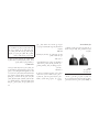
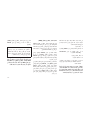
Important Safety Precautions
Please pay close attention to the information in
this section. It tells you how to use your restraint
system properly, to keep you and your passengers as safe as possible.
30
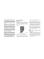
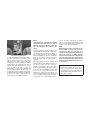
Warning Label On Front Passenger Sun Visor
2. If a child from 2 to 12 years old (not in a
rear-facing child restraint) must ride in the
front passenger seat, move the seat as far
back as possible and use the proper child
restraint. (Refer to “Child Restraints”)
7. The driver and front passenger seats should
be moved back as far as practical to allow
the Advanced Front Air Bags room to inflate.
8. Do not lean against the door or window. If
your vehicle has side air bags, and deployment occurs, the side air bags will inflate
forcefully into the space between you and
the door and you could be injured.
collision that includes you. This can happen far
away from home or on your own street.
9. If the air bag system in this vehicle needs to
be modified to accommodate a disabled
person, contact the Customer Center. Phone
numbers are provided under "If You Need
Assistance."
Research has shown that seat belts save lives,
and they can reduce the seriousness of injuries
in a collision. Some of the worst injuries happen
when people are thrown from the vehicle. Seat
belts reduce the possibility of ejection and the
risk of injury caused by striking the inside of the
vehicle. Everyone in a motor vehicle should be
belted at all times.
WARNING!
• Never place a rear-facing child restraint in
front of an air bag. A deploying Passenger
Advanced Front Air Bag can cause death
or serious injury to a child 12 years or
younger, including a child in a rear-facing
child restraint.
• Only use rear-facing child restraint in a
vehicle with a rear seat.
Seat Belt Systems
Buckle up even though you are an excellent
driver, even on short trips. Someone on the
road may be a poor driver and could cause a
Enhanced Seat Belt Use Reminder System
(BeltAlert)
Front Seat Driver And Passenger
BeltAlert
BeltAlert is a feature intended to remind the
driver and front passenger to fasten their seat
belts. The feature is active whenever the ignition is in the START or ON/RUN position. If the
driver or front seat passenger is unbelted, the
respective Seat Belt Reminder Light will illuminate solid red and remain on until the seat belt
is fastened. The respective Seat Belt Reminder
Light will illuminate solid green once the occupied seating position seat belt is buckled.
The BeltAlert warning sequence begins after
the vehicle speed is over 5 mph (8 km/h), by
blinking the respective Seat Belt Reminder
Light and sounding an intermittent chime. Once
the sequence starts, it will continue for the entire
duration or until the respective seatbelts are
fastened. After the sequence completes, the
Seat Belt Reminder Light remains illuminated
until the respective seat belts are fastened. The
driver should instruct all other occupants to
fasten their seat belts. If a front seat belt is
unbuckled while traveling at speeds greater
than 5 mph (8 km/h), BeltAlert will provide both
audio and visual notification.
The front passenger seat BeltAlert is not active
when the front passenger seat is unoccupied.
BeltAlert may be triggered when an animal or
heavy object is on the front passenger seat or
when the seat is folded flat (if equipped). It is
recommended that pets be restrained in the
rear seat (if equipped) in pet harnesses or pet
carriers that are secured by seat belts, and
cargo is properly stowed.
BeltAlert can be activated or deactivated by
your authorized dealer. Chrysler Group LLC
does not recommend deactivating BeltAlert.
31
NOTE:
If BeltAlert has been deactivated, the Seat
Belt Reminder Light will continue to illuminate while the driver’s or outboard front
passenger’s (if equipped with BeltAlert) seat
belt remains unbuckled.
Rear Seat BeltAlert — If Equipped
Rear Seat BeltAlert shows the driver whether
the seat belts in the back seat are buckled or
unbuckled. When the ignition switch is in the
START or ON/RUN position, a Seat Belt Reminder Light turns on for each rear seat position. If the seat belt is buckled, the light for that
position will illuminate solid green. If the seat
belt is unbuckled, the light will illuminate red. If
a rear passenger unbuckles a seat belt that was
buckled at the start of the trip, a single chime will
sound and the Seat Belt Reminder Light for that
position will change from solid green to blinking
red. This will alert the driver to stop the vehicle
until the rear passenger buckles the seat belt
again.
NOTE:
• If BeltAlert has been deactivated, the Seat
Belt Reminder Lights will remain illuminated when the ignition switch is in the
START or ON/RUN position.
• If all seat belts are buckled when ignition
switch is in the START or ON/RUN position, each Seat Belt Reminder Light will
illuminate solid green for approximately
30 seconds, then turn off.
Lap/Shoulder Belts
All seating positions in your vehicle are
equipped with lap/shoulder belts.
The seat belt webbing retractor will lock only
during very sudden stops or collisions. This
feature allows the shoulder part of the seat belt
to move freely with you under normal conditions. However, in a collision the seat belt will
lock and reduce your risk of striking the inside of
the vehicle or being thrown out of the vehicle.
WARNING!
• Relying on the air bags alone could lead to
more severe injuries in a collision. The air
bags work with your seat belt to restrain
you properly. In some collisions, the air
bags won’t deploy at all. Always wear your
seat belt even though you have air bags.
• In a collision, you and your passengers
can suffer much greater injuries if you are
not properly buckled up. You can strike the
interior of your vehicle or other passengers, or you can be thrown out of the
vehicle. Always be sure you and others in
your vehicle are buckled up properly.
• It is dangerous to ride in a cargo area,
inside or outside of a vehicle. In a collision,
people riding in these areas are more likely
to be seriously injured or killed.
• Do not allow people to ride in any area of
your vehicle that is not equipped with seats
and seat belts.
(Continued)
32
WARNING! (Continued)
• Be sure everyone in your vehicle is in a
seat and using a seat belt properly.
• Wearing your seat belt incorrectly could
make your injuries in a collision much
worse. You might suffer internal injuries, or
you could even slide out of the seat belt.
Follow these instructions to wear your seat
belt safely and to keep your passengers
safe, too.
• Two people should never be belted into a
single seat belt. People belted together
can crash into one another in a collision,
hurting one another badly. Never use a
lap/shoulder belt or a lap belt for more than
one person, no matter what their size.
• A lap belt worn too high can increase the
risk of injury in a collision. The seat belt
forces won’t be at the strong hip and pelvic
bones, but across your abdomen. Always
wear the lap part of your seat belt as low as
possible and keep it snug.
WARNING! (Continued)
• A twisted seat belt may not protect you
properly. In a collision, it could even cut
into you. Be sure the seat belt is flat
against your body, without twists. If you
can’t straighten a seat belt in your vehicle,
take it to your authorized dealer immediately and have it fixed.
• A seat belt that is buckled into the wrong
buckle will not protect you properly. The
lap portion could ride too high on your
body, possibly causing internal injuries.
Always buckle your seat belt into the
buckle nearest you.
• A seat belt that is too loose will not protect
you properly. In a sudden stop, you could
move too far forward, increasing the possibility of injury. Wear your seat belt snugly.
WARNING! (Continued)
• A seat belt that is worn under your arm is
dangerous. Your body could strike the inside surfaces of the vehicle in a collision,
increasing head and neck injury. A seat
belt worn under the arm can cause internal
injuries. Ribs aren’t as strong as shoulder
bones. Wear the seat belt over your shoulder so that your strongest bones will take
the force in a collision.
• A shoulder belt placed behind you will not
protect you from injury during a collision.
You are more likely to hit your head in a
collision if you do not wear your shoulder
belt. The lap and shoulder belt are meant
to be used together.
(Continued)
(Continued)
(Continued)
33
WARNING! (Continued)
• A frayed or torn seat belt could rip apart in
a collision and leave you with no protection. Inspect the seat belt system periodically, checking for cuts, frays, or loose
parts. Damaged parts must be replaced
immediately. Do not disassemble or modify
the seat belt system. Seat belt assemblies
must be replaced after a collision.
Lap/Shoulder Belt Operating Instructions
1. Enter the vehicle and close the door. Sit
back and adjust the seat.
2. The seat belt latch plate is above the back of
the front seat, and next to your arm in the
rear seat (for vehicles equipped with a rear
seat). Grasp the latch plate and pull out the
seat belt. Slide the latch plate up the webbing as far as necessary to allow the seat
belt to go around your lap.
34
Pulling Out The Latch Plate
Inserting Latch Plate Into Buckle
3. When the seat belt is long enough to fit,
insert the latch plate into the buckle until you
hear a “click.”
4. Position the lap belt so that it is snug and lies
low across your hips, below your abdomen.
To remove slack in the lap belt portion, pull
up on the shoulder belt. To loosen the lap
belt if it is too tight, tilt the latch plate and pull
on the lap belt. A snug seat belt reduces the
risk of sliding under the seat belt in a collision.
Lap/Shoulder Belt Untwisting Procedure
Use the following procedure to untwist a twisted
lap/shoulder belt.
1. Position the latch plate as close as possible
to the anchor point.
2. At about 6 to 12 inches (15 to 30 cm) above
the latch plate, grasp and twist the seat belt
webbing 180° to create a fold that begins
immediately above the latch plate.
Positioning The Lap Belt
5. Position the shoulder belt across the shoulder and chest with minimal, if any slack so
that it is comfortable and not resting on your
neck. The retractor will withdraw any slack in
the shoulder belt.
6. To release the seat belt, push the red button
on the buckle. The seat belt will automatically retract to its stowed position. If necessary, slide the latch plate down the webbing
to allow the seat belt to retract fully.
3. Slide the latch plate upward over the folded
webbing. The folded webbing must enter the
slot at the top of the latch plate.
4. Continue to slide the latch plate up until it
clears the folded webbing and the seat belt
is no longer twisted.
Adjustable Upper Shoulder Belt Anchorage
In the driver and front passenger seats, the top
of the shoulder belt can be adjusted upward or
downward to position the seat belt away from
your neck. Push or squeeze the anchorage
button to release the anchorage, and move it up
or down to the position that serves you best.
Adjustable Anchorage
As a guide, if you are shorter than average, you
will prefer the shoulder belt anchorage in a
lower position, and if you are taller than average, you will prefer the shoulder belt anchorage
in a higher position. After you release the anchorage button, try to move it up or down to
make sure that it is locked in position.
35
NOTE:
The adjustable upper shoulder belt anchorage is equipped with an Easy Up feature.
This feature allows the shoulder belt anchorage to be adjusted in the upward position without pushing or squeezing the release button. To verify the shoulder belt
anchorage is latched, pull downward on the
shoulder belt anchorage until it is locked
into position.
Seat Belts And Pregnant Women
We recommend that pregnant women use the
seat belts throughout their pregnancy. Keeping
the mother safe is the best way to keep the baby
safe.
Pregnant women should wear the lap part of the
seat belt across the thighs and as snug across
the hips as possible. Keep the seat belt low so
that it does not come across the abdomen. That
way the strong bones of the hips will take the
force if there is a collision.
Seat Belt Pretensioner
The front seat belt system is equipped with
pretensioning devices that are designed to re36
move slack from the seat belt in the event of a
collision. These devices may improve the performance of the seat belt by removing slack
from the seat belt early in a collision. Pretensioners work for all size occupants, including
those in child restraints.
NOTE:
These devices are not a substitute for
proper seat belt placement by the occupant.
The seat belt still must be worn snugly and
positioned properly.
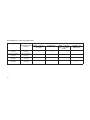
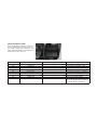
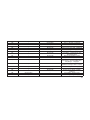
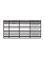
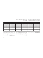
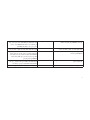
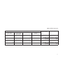
Automatic Locking Retractor (ALR) — If
Equipped
The seat belts in the passenger seating positions may be equipped with a Switchable Automatic Locking Retractor (ALR) which is used to
secure a child restraint system. For additional
information, refer to “Installing Child Restraints
Using The Vehicle Seat Belt” under the “Child
Restraints” section of this manual. The table
below defines the type of feature for each
seating position.
The pretensioners are triggered by the Occupant Restraint Controller (ORC). Like the air
bags, the pretensioners are single use items. A
deployed pretensioner or a deployed air bag
must be replaced immediately.
Energy Management Feature
This vehicle has a seat belt system with an
Energy Management feature in the front seating
positions that may help further reduce the risk of
injury in the event of a collision. This seat belt
system has a retractor assembly that is designed to release webbing in a controlled manner.
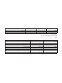
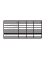
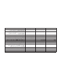
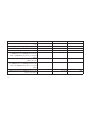
• ALR = Switchable Automatic Locking Retractor
If the passenger seating position is equipped
with an ALR and is being used for normal
usage, only pull the seat belt webbing out far
enough to comfortably wrap around the occupant’s mid-section so as to not activate the ALR.
If the ALR is activated, you will hear a clicking
sound as the seat belt retracts. Allow the webbing to retract completely in this case and then
carefully pull out only the amount of webbing
necessary to comfortably wrap around the occupant’s mid-section. Slide the latch plate into
the buckle until you hear a "click."
In Automatic Locking Mode, the shoulder belt is
automatically pre-locked. The seat belt will still
retract to remove any slack in the shoulder belt.
Use the Automatic Locking Mode anytime a
child restraint is installed in a seating position
that has a seat belt with this feature. Children 12
years old and under should always be properly
restrained in a vehicle with a rear seat.
WARNING!
• Never place a rear-facing child restraint in
front of an air bag. A deploying Passenger
Advanced Front Air Bag can cause death
or serious injury to a child 12 years or
younger, including a child in a rear-facing
child restraint.
• Only use rear-facing child restraint in a
vehicle with a rear seat.
Supplemental Restraint System
(SRS)
Air Bag System Components
Your vehicle may be equipped with the following
air bag system components:
• Occupant Restraint Controller (ORC)
• Air Bag Warning Light
• Steering Wheel and Column
• Knee Impact Bolsters
• Advanced Front Air Bags
• Supplemental Side Air Bags
• Supplemental Knee Air Bags
• Front and Side Impact Sensors
• Seat Belt Pretenioners
• Seat Belt Buckle Switch
• Occupant Classification System
Advanced Front Air Bags
This vehicle has Advanced Front Air Bags for
both the driver and front passenger as a supplement to the seat belt restraint systems. The
driver’s Advanced Front Air Bag is mounted in
the center of the steering wheel. The passenger’s Advanced Front Air Bag is mounted in the
instrument panel, above the glove compartment. The words “SRS AIRBAG” or “AIRBAG”
are embossed on the air bag covers.
• Instrument Panel
37
Advanced Front Air Bag And Knee Bolster
Locations
1 — Driver Advanced
Front Air Bag
2 — Passenger Advanced Front Air Bag
3 — Supplemental
Driver Knee Air Bag/
Driver Knee Impact Bolster
4 — Passenger Knee
Bolster
WARNING!
• Being too close to the steering wheel or
instrument panel during Advanced Front
Air Bag deployment could cause serious
injury, including death. Air bags need room
to inflate. Sit back, comfortably extending
your arms to reach the steering wheel or
instrument panel.
• Never place a rear-facing child restraint in
front of an air bag. A deploying Passenger
Advanced Front Air Bag can cause death
or serious injury to a child 12 years or
younger, including a child in a rear-facing
child restraint.
• Only use a rear-facing child restraint in a
vehicle with a rear seat.
Advanced Front Air Bag Features
The Advanced Front Air Bag system provides
output appropriate to the severity and type of
collision as determined by the Occupant Restraint Controller (ORC), which may receive
information from the front impact sensors or
other system components.
38
This vehicle may be equipped with a driver
and/or front passenger seat belt buckle switch
that detects whether the driver or front passenger seat belt is buckled. The seat belt buckle
switch may adjust the inflation rate of the Advanced Front Air Bags.
WARNING!
• No objects should be placed over or near
the air bag on the instrument panel or
steering wheel, because any such objects
could cause harm if the vehicle is in a
collision severe enough to cause the air
bags to inflate.
• Do not put anything on or around the air
bag covers or attempt to open them manually. You may damage the air bags and you
could be injured because the air bags may
no longer be functional. The protective
covers for the air bag cushions are designed to open only when the air bags are
inflating.
(Continued)
WARNING! (Continued)
• Relying on the air bags alone could lead to
more severe injuries in a collision. The air
bags work with your seat belt to restrain
you properly. In some collisions, air bags
won’t deploy at all. Always wear your seat
belts even though you have air bags.
Advanced Front Air Bag Operation
Advanced Front Air Bags are designed to provide additional protection by supplementing the
seat belts. Advanced Front Air Bags are not
expected to reduce the risk of injury in rear,
side, or rollover collisions. The Advanced Front
Air Bags will not deploy in all frontal collisions,
including some that may produce substantial
vehicle damage — for example, some pole
collisions, truck underrides, and angle offset
collisions.
On the other hand, depending on the type and
location of impact, Advanced Front Air Bags
may deploy in crashes with little vehicle frontend damage but that produce a severe initial
deceleration.
Because air bag sensors measure vehicle deceleration over time, vehicle speed and damage
by themselves are not good indicators of
whether or not an air bag should have deployed.
Seat belts are necessary for your protection in
all collisions, and also are needed to help keep
you in position, away from an inflating air bag.
When the ORC detects a collision requiring the
Advanced Front Air Bags, it signals the inflator
units. A large quantity of non-toxic gas is generated to inflate the Advanced Front Air Bags.
The steering wheel hub trim cover and the
upper right side of the instrument panel separate and fold out of the way as the air bags
inflate to their full size. The Advanced Front Air
Bags fully inflate in less time than it takes to
blink your eyes. The air bags then quickly
deflate while helping to restrain the driver and
front passenger.
Occupant Classification System (OCS) —
Front Passenger Seat
The OCS is part of a Federally regulated safety
system for this vehicle. It is designed to provide
Passenger Advanced Front Air Bag output ap-
propriate to the occupant’s seated weight, as
determined by the OCS.
The Occupant Classification System (OCS)
consists of the following:
• Occupant Restraint Controller (ORC)
• Occupant Classification Module (OCM) and
Sensor located in the front passenger seat
• Air Bag Warning Light
Occupant Classification Module (OCM) and
Sensor
The Occupant Classification Module (OCM) is
located underneath the front passenger seat.
The Sensor is located beneath the passenger
seat cushion foam. Any weight on the seat will
be sensed by the Sensor. The OCM uses input
from the Sensor to determine the front passenger’s most probable classification. The OCM
communicates this information to the ORC. The
ORC may reduce the inflation rate of the Passenger Advanced Front Air Bag deployment
based on occupant classification. In order for
the OCS to operate as designed, it is important
for the front passenger to be seated properly
and properly wearing the seat belt.
39
The OCS will NOT prevent deployment of the
Passenger Advanced Front Air Bag. The OCS
may reduce the inflation rate of the Passenger
Advanced Front Air Bag if the OCS estimates that:
Front Passenger
Seat Occupant
Status
Front Passenger
Air Bag Output
• The front passenger seat is unoccupied or
has very light objects on it; or
Properly seated adult
Full-power deployment OR reducedpower deployment
Unoccupied seat
Reduced-power
deployment
• The front passenger seat is occupied by a
small passenger, including a child; or
• The front passenger seat is occupied by a
rear-facing child restraint; or
• The front passenger is not properly seated or
his or her weight is taken off of the seat for a
period of time.
Front Passenger
Seat Occupant
Status
Front Passenger
Air Bag Output
Rear-facing child restraint
Reduced-power
deployment
Child, including a
child in a forwardfacing child restraint
or booster seat*
Reduced-power
deployment OR
Full-power deployment
* It is possible for a child to be classified as an
adult, allowing a full-power Passenger Advanced
Front Air Bag deployment. Never allow children to
ride in the front passenger seat and never install a
child restraint system, including a rear-facing child
restraint, in the front passenger seat.
WARNING!
• Never place a rear-facing child restraint in
front of an air bag. A deploying Passenger
Advanced Front Air Bag can cause death
or serious injury to a child 12 years or
younger, including a child in a rear-facing
child restraint.
(Continued)
40
WARNING! (Continued)
• Only use rear-facing child restraint in a
vehicle with a rear seat.
• Children 12 years or younger should always ride buckled up in a rear seat.
The OCS determines the front passenger’s
most probable classification. The OCS estimates the seated weight on the front passenger
seat and where that weight is located. The OCS
communicates the classification status to the
ORC. The ORC uses the classification to determine whether the Passenger Advanced Front
Air Bag inflation rate should be adjusted.
In order for the OCS to operate as designed, it
is important for the front passenger to be seated
properly and properly wearing the seat belt.
Properly seated passengers are:
• Sitting upright
• Facing forward
• Sitting in the center of the seat with their feet
comfortably on or near the floor
• Sitting with their back against the seatback
and the seatback in an upright position
The front passenger’s seated weight must be
properly positioned on the front passenger seat.
Failure to do so may result in serious injury or
death. The OCS determines the most probable
classification of the occupant that it detects.
The OCS will detect the front passenger’s decreased or increased seated weight, which may
result in an adjusted inflation rate of the Passenger Advanced Front Air Bag in a collision.
This does not mean that the OCS is working
improperly.
Seated Properly
Lighter Weight Passengers (Including
Small Adults)
When a lighter weight passenger, including a
small adult, occupies the front passenger seat,
the OCS may reduce the inflation rate of the
Passenger Advanced Front Air Bag. This does
not mean that the OCS is working improperly.
Do not decrease OR increase the front passenger’s seated weight on the front passenger seat
Decreasing the front passenger’s seated weight
on the front passenger seat may result in a
reduced-power deployment of the Passenger
Advanced Front Air Bag. Increasing the front
passenger’s seated weight on the front passenger seat may result in a full-power deployment
of the Passenger Advanced Front Air Bag.
• The front passenger leans forward, sideways, or turns to face the rear of the vehicle.
• The front passenger’s seatback is not in the
full upright position.
• The front passenger carries or holds an
object while seated (e.g., backpack, box,
etc.)
• Objects are lodged under the front passenger seat.
• Objects are lodged between the front passenger seat and center console.
• Accessories that may change the seated
weight on the front passenger seat are attached to the front passenger seat.
• Anything that may decrease or increase the
front passenger’s seated weight.
Examples of improper front passenger seating
include:
• The front passenger’s weight is transferred to
another part of the vehicle (like the door, arm
rest or instrument panel).
41
The OCS determines the front passenger’s
most probable classification. If an occupant in
the front passenger seat is seated improperly,
the occupant may provide an output signal to
the OCS that is different from the occupant’s
properly seated weight input, for example:
Not Seated Properly
Not Seated Properly
WARNING!
• If an occupant in the front passenger seat
is seated improperly, the occupant may
provide an output signal to the OCS that is
different from the occupant’s properly
seated weight input. This may result in
serious injury or death in a collision.
Not Seated Properly
(Continued)
Not Seated Properly
42
WARNING! (Continued)
• Always wear your seat belt and sit properly, with the seatback in an upright position, your back against the seatback, sitting upright, facing forward, in the center of
the seat, with your feet comfortably on or
near the floor.
• Do not carry or hold any objects (e.g.,
backpacks, boxes, etc.) while seated in the
front passenger seat. Holding an object
may provide an output signal to the OCS
that is different than the occupant’s properly seated weight input, which may result
in serious injury or death in a collision.
• Placing an object on the floor under the
front passenger seat may prevent the OCS
from working properly, which may result in
serious injury or death in a collision. Do not
place any objects on the floor under the
front passenger seat.
will turn on whenThe Air Bag Warning Light
ever the OCS is unable to classify the front
passenger seat status. A malfunction in the
OCS may affect the operation of the air bag
system.
If the Air Bag Warning Light
does not come
on, or stays on after you start the vehicle, or it
comes on as you drive, take the vehicle to an
authorized dealer for service immediately.
The passenger seat assembly contains critical
OCS components that may affect the Passenger Advanced Front Air Bag inflation. In order
for the OCS to properly classify the seated
weight of a front seat passenger, the OCS
components must function as designed.
Do not make any modifications to the front
passenger seat components, assembly, or to
the seat cover. If the seat, trim cover, or cushion
needs service for any reason, take the vehicle
to your authorized dealer. Only Chrysler Group
LLC approved seat accessories may be used.
The following requirements must be strictly followed:
• Do not modify the front passenger seat assembly or components in any way.
• Do not use prior or future model year seat
covers or cushions not designated by
Chrysler Group LLC for the specific model
being repaired. Always use the correct seat
cover and cushion specified for the vehicle.
• Do not replace the seat cover or cushion with
an aftermarket seat cover or cushion.
• Do not add a secondary seat cover or mat.
• At no time should any Supplemental Restraint System (SRS) component or SRS
related component or fastener be modified or
replaced with any part except those which
are approved by Chrysler Group LLC.
WARNING!
Unapproved modifications or service procedures to the passenger seat assembly, its
related components, seat cover or cushion
may inadvertently change the air bag deployment in case of a frontal collision. This could
result in death or serious injury to the front
passenger if the vehicle is involved in a
(Continued)
43
WARNING! (Continued)
collision. A modified vehicle may not comply
with required Federal Motor Vehicle Safety
Standards (FMVSS) and/or Canadian Motor
Vehicle Safety Standards (CMVSS).
Knee Impact Bolsters
The Knee Impact Bolsters help protect the
knees of the driver and front passenger, and
position the front occupants for improved interaction with the Advanced Front Air Bags.
protection during a frontal impact by working
together with the seat belts, pretensioners, and
Advanced Front Air Bags.
Supplemental Side Air Bags
Your vehicle is equipped with two types of side
air bags:
1. Supplemental Seat-Mounted Side Air Bags
(SABs): Located in the outboard side of the
front seats. The SABs are marked with a
“SRS AIRBAG” or “AIRBAG” label sewn into
the outboard side of the seats.
WARNING!
• Do not drill, cut, or tamper with the knee
impact bolsters in any way.
• Do not mount any accessories to the knee
impact bolsters such as alarm lights, stereos, citizen band radios, etc.
Supplemental Knee Air Bags
This vehicle is equipped with a Supplemental
Driver Knee Air Bag mounted in the instrument
panel below the steering column. The Supplemental Driver Knee Air Bag provides enhanced
44
Front Supplemental Seat-Mounted Side Air
Bag Label
The SABs may help to reduce the risk of
occupant injury during certain side impact and
certain rollover events, in addition to the injury
reduction potential provided by the seat belts
and body structure.
When the SAB deploys, it opens the seam on
the outboard side of the seatback’s trim cover.
The inflating SAB deploys through the seat
seam into the space between the occupant and
the door. The SAB moves at a very high speed
and with such a high force that it could injure
you if you are not seated properly, or if items are
positioned in the area where the SAB inflates.
Children are at an even greater risk of injury
from a deploying air bag.
WARNING!
Do not use accessory seat covers or place
objects between you and the Side Air Bags;
the performance could be adversely affected
and/or objects could be pushed into you,
causing serious injury.
2. Supplemental Side Air Bag Inflatable Curtains (SABICs): Located above the side windows. The trim covering the SABICs is labeled “SRS AIRBAG” or “AIRBAG.”
The SABICs deploy downward, covering the
side windows. An inflating SABIC pushes the
outside edge of the trim out of the way and
covers the window. The SABICs inflate with
enough force to injure you if you are not belted
and seated properly, or if items are positioned in
the area where the SABICs inflate. Children are
at an even greater risk of injury from a deploying
air bag.
The SABICs may help reduce the risk of partial
or complete ejection of vehicle occupants
through side windows in certain rollover or side
impact events.
Supplemental Side Air Bag Inflatable Curtain
(SABIC) Label Location
SABICs may help reduce the risk of head injury
to front and rear seat outboard occupants.
SABICs may reduce the risk of injuries in certain
side impact and vehicle rollover events, in addition to the injury reduction potential provided
by the seat belts and body structure.
WARNING!
• Your vehicle is equipped with left and right
Supplemental Side Air Bag Inflatable Curtains (SABICs). Do not stack luggage or
other cargo up high enough to block the
deployment of the SABICs. The trim covering above the side windows where the
SABIC and its deployment path are located
should remain free from any obstructions.
(Continued)
WARNING! (Continued)
• Your vehicle is equipped with SABICs. In
order for the SABICs to work as intended,
do not install any accessory items in your
vehicle which could alter the roof. Do not
add an aftermarket sunroof to your vehicle.
Do not add roof racks that require permanent attachments (bolts or screws) for installation on the vehicle roof. Do not drill
into the roof of the vehicle for any reason.
The SABICs and SABs (“Side Air Bags”) are
designed to activate in certain side impacts and
certain rollover events. The Occupant Restraint
Controller (“ORC”) determines whether the deployment of the Side Air Bags in a particular
side impact or rollover event is appropriate,
based on the severity and type of collision.
Vehicle damage by itself is not a good indicator
of whether or not Side Air Bags should have
deployed.
Side Air Bags are a supplement to the seat belt
restraint system. Side Air Bags deploy in less
time than it takes to blink your eyes. Occupants,
45
including children, who are up against or very
close to Side Air Bags can be seriously injured
or killed. Occupants, including children, should
never lean on or sleep against the door, side
windows, or area where the Side Air Bags
inflate, even if they are in an infant or child
restraint.
Seat belts (and child restraints where appropriate) are necessary for your protection in all
collisions. They also help keep you in position,
away from inflating Side Air Bags. To get the
best protection from the Side Air Bags, occupants must wear their seat belts properly and sit
upright with their backs against the seats. Children must be properly restrained in a child
restraint or booster seat that is appropriate for
the size of the child.
WARNING!
• Side Air Bags need room to inflate. Do not
lean against the door or window. Sit upright in the center of the seat.
(Continued)
46
WARNING! (Continued)
• Being too close to the Side Air Bags during
deployment could cause you to be severely injured or killed.
• Relying on the Side Air Bags alone could
lead to more severe injuries in a collision.
The Side Air Bags work with your seat belt
to restrain you properly. In some collisions,
Side Air Bags won’t deploy at all. Always
wear your seat belt even though you have
Side Air Bags.
Side Air Bags deploy independently; a left side
impact deploys the left Side Air Bags only and a
right side impact deploys the right Side Air Bags
only.
The Side Air Bags will not deploy in all side
collisions, including some collisions at certain
angles, or some side collisions that do not
impact the area of the passenger compartment.
The Side Air Bags may deploy during angled or
offset frontal collisions where the Advanced
Front Air Bags deploy.
Rollover Events
Side Impacts
Side Air Bags are designed to activate in certain
rollover events. The ORC determines whether
the deployment of the Side Air Bags in a particular rollover event is appropriate, based on
the severity and type of collision. Vehicle damage by itself is not a good indicator of whether or
not Side Air Bags should have deployed.
In side impacts, the side impact sensors aid the
ORC in determining the appropriate response
to impact events. The system is calibrated to
deploy the Side Air Bags on the impact side of
the vehicle during impacts that require Side Air
Bag occupant protection. In side impacts, the
The Side Air Bags will not deploy in all rollover
events. The rollover sensing-system determines if a rollover event may be in progress and
whether deployment is appropriate. A slowerdeveloping event may deploy the seat belt
pretensioners on both sides of the vehicle. A
NOTE:
Air bag covers may not be obvious in the
interior trim, but they will open during air
bag deployment.
faster-developing event may deploy the seat
belt pretensioners as well as the SABs and
SABICs on both sides of the vehicle. The rollover sensing-system may also deploy the seat
belt pretensioners, with or without the SABs and
SABICs, on both sides of the vehicle if the
vehicle experiences a near rollover event.
If A Deployment Occurs
The Advanced Front Air Bags are designed to
deflate immediately after deployment.
NOTE:
Front and/or side air bags will not deploy in
all collisions. This does not mean something is wrong with the air bag system.
If you do have a collision, which deploys the air
bags, any or all of the following may occur:
• The air bag material may sometimes cause
abrasions and/or skin reddening to the occupants as the air bags deploy and unfold. The
abrasions are similar to friction rope burns or
those you might get sliding along a carpet or
gymnasium floor. They are not caused by
contact with chemicals. They are not permanent and normally heal quickly. However, if
you haven’t healed significantly within a few
days, or if you have any blistering, see your
doctor immediately.
• As the air bags deflate, you may see some
smoke-like particles. The particles are a normal by-product of the process that generates
the non-toxic gas used for air bag inflation.
These airborne particles may irritate the skin,
eyes, nose, or throat. If you have skin or eye
irritation, rinse the area with cool water. For
nose or throat irritation, move to fresh air. If
the irritation continues, see your doctor. If
these particles settle on your clothing, follow
the garment manufacturer’s instructions for
cleaning.
Do not drive your vehicle after the air bags have
deployed. If you are involved in another collision,
the air bags will not be in place to protect you.
WARNING!
Deployed air bags and seat belt pretensioners cannot protect you in another collision.
Have the air bags, seat belt pretensioners,
(Continued)
WARNING! (Continued)
and the seat belt retractor assemblies replaced by an authorized dealer immediately.
Also, have the Occupant Restraint Controller
System serviced as well.
NOTE:
• Air bag covers may not be obvious in the
interior trim, but they will open during air
bag deployment.
• After any collision, the vehicle should be
taken to an authorized dealer immediately.
Enhanced Accident Response System
In the event of an impact, if the communication
network remains intact, and the power remains
intact, depending on the nature of the event, the
ORC will determine whether to have the Enhanced Accident Response System perform the
following functions:
• Cut off fuel to the engine.
• Flash hazard lights as long as the battery has
power or until the ignition switch is turned to
the “OFF” position.
47
• Turn on the interior lights, which remain on as
long as the battery has power or until the
ignition switch is turned to the “OFF” position.
• Unlock the doors automatically.
System Reset Procedure
In order to reset the Enhanced Accident Response System functions after an event, the
ignition switch must be changed from ignition
START or ON/RUN to ignition OFF.
Air Bag Warning Light
The air bags must be ready to
inflate for your protection in a collision. The Occupant Restraint Controller (ORC) monitors the internal
circuits and interconnecting wiring
associated with air bag system
electrical components.
The ORC monitors the readiness of the electronic parts of the air bag system whenever the
ignition switch is in the START or ON/RUN
position. If the ignition switch is in the OFF
position or in the ACC position, the air bag
system is not on and the air bags will not inflate.
48
The ORC contains a backup power supply
system that may deploy the air bags even if the
battery loses power or it becomes disconnected
prior to deployment.
• The Air Bag Warning Light does not come on
during the four to eight seconds when the
ignition switch is first turned to the ON/RUN
position.
The ORC turns on the Air Bag Warning Light in
the instrument panel for approximately four to
eight seconds for a self-check when the ignition
switch is first turned to the ON/RUN position.
After the self-check, the Air Bag Warning Light
will turn off. If the ORC detects a malfunction in
any part of the system, it turns on the Air Bag
Warning Light, either momentarily or continuously. A single chime will sound to alert you if
the light comes on again after initial startup.
• The Air Bag Warning Light remains on after
the four to eight-second interval.
The ORC also includes diagnostics that will
illuminate the instrument panel Air Bag Warning
Light if a malfunction is detected that could
affect the air bag system. The diagnostics also
record the nature of the malfunction. While the
air bag system is designed to be maintenance
free, if any of the following occurs, have an
authorized dealer service the air bag system
immediately.
• The Air Bag Warning Light comes on intermittently or remains on while driving.
NOTE:
If the speedometer, tachometer, or any engine related gauges are not working, the
Occupant Restraint Controller (ORC) may
also be disabled. In this condition the air
bags may not be ready to inflate for your
protection. Have an authorized dealer service the air bag system immediately.
WARNING!
Ignoring the Air Bag Warning Light in your
instrument panel could mean you won’t have
the air bags to protect you in a collision. If the
(Continued)
WARNING! (Continued)
light does not come on as a bulb check when
the ignition is first turned on, stays on after
you start the vehicle, or if it comes on as you
drive, have an authorized dealer service the
air bag system immediately.
Redundant Air Bag Warning Light
If a fault with the Air Bag Warning
Light is detected, which could affect the Supplemental Restraint
System (“SRS”), the Redundant
Warning Light will illuminate on the
instrument panel.
The Redundant Warning Light will stay on until
the fault is cleared. In addition, a single chime
will sound to alert you that the Redundant
Warning Light has come on and a fault has
been detected. If the Redundant Warning Light
comes on intermittently or remains on while
driving have an authorized dealer service the
vehicle immediately.
For additional information regarding the Redundant Warning Light refer to the “Instrument
Panel” section of this manual.
Maintaining Your Air Bag System
WARNING!
• Modifications to any part of the air bag
system could cause it to fail when you
need it. You could be injured if the air bag
system is not there to protect you. Do not
modify the components or wiring, including
adding any kind of badges or stickers to
the steering wheel hub trim cover or the
upper right side of the instrument panel.
Do not modify the front bumper, vehicle
body structure, or add aftermarket side
steps or running boards.
• It is dangerous to try to repair any part of
the air bag system yourself. Be sure to tell
anyone who works on your vehicle that it
has an air bag system.
(Continued)
WARNING! (Continued)
• Do not attempt to modify any part of your air
bag system. The air bag may inflate accidentally or may not function properly if modifications are made. Take your vehicle to an
authorized dealer for any air bag system
service. If your seat, including your trim
cover and cushion, needs to be serviced in
any way (including removal or loosening/
tightening of seat attachment bolts), take the
vehicle to your authorized dealer. Only
manufacturer approved seat accessories
may be used. If it is necessary to modify the
air bag system for persons with disabilities,
contact your authorized dealer.
Event Data Recorder (EDR)
This vehicle is equipped with an event data
recorder (EDR). The main purpose of an EDR is
to record, in certain crash or near crash-like
situations, such as an air bag deployment or
hitting a road obstacle, data that will assist in
understanding how a vehicle’s systems performed. The EDR is designed to record data
49
related to vehicle dynamics and safety systems
for a short period of time, typically 30 seconds
or less. The EDR in this vehicle is designed to
record such data as:
• How various systems in your vehicle were
operating.
• Whether or not the driver and passenger
safety belts were buckled/fastened.
• How far (if at all) the driver was pushing the
accelerator and/or brake pedal.
To read data recorded by an EDR, special
equipment is required, and access to the vehicle or the EDR is needed. In addition to the
vehicle manufacturer, other parties, such as law
enforcement, that have the special equipment,
can read the information if they have access to
the vehicle or the EDR.
• How fast the vehicle was traveling.
Children 12 years or younger should ride properly buckled up in a rear seat, if available.
According to crash statistics, children are safer
when properly restrained in the rear seats
rather than in the front.
These data can help provide a better understanding of the circumstances in which crashes
and injuries occur.
NOTE:
EDR data are recorded by your vehicle only if
a non-trivial crash situation occurs; no data
are recorded by the EDR under normal driving
conditions and no personal data (e.g., name,
gender, age, and crash location) are recorded.
However, other parties, such as law enforcement, could combine the EDR data with the
type of personally identifying data routinely
acquired during a crash investigation.
50
Child Restraints
Everyone in your vehicle needs to be buckled
up at all times, including babies and children.
WARNING!
In a collision, an unrestrained child can become a projectile inside the vehicle. The
force required to hold even an infant on your
lap could become so great that you could not
hold the child, no matter how strong you are.
(Continued)
WARNING! (Continued)
The child and others could be badly injured.
Any child riding in your vehicle should be in a
proper restraint for the child’s size.
There are different sizes and types of restraints
for children from newborn size to the child
almost large enough for an adult seat belt.
Always check the child seat Owner’s Manual to
make sure you have the correct seat for your
child. Carefully read and follow all the instructions and warnings in the child restraint Owner’s
Manual and on all the labels attached to the
child restraint.
Before buying any restraint system, make sure
that it has a label certifying that it meets all
applicable Safety Standards. You should also
make sure that you can install it in the vehicle
where you will use it.
Summary Of Recommendations For Restraining Children In Vehicles
Child Size, Height, Weight Or Age
Recommended Type Of Child Restraint
Infants and Toddlers
Children who are two years old or younger
and who have not reached the height or
weight limits of their child restraint
Either an Infant Carrier or a Convertible Child
Restraint, facing rearward in the rear seat of
the vehicle
Small Children
Children who are at least two years old or
who have out-grown the height or weight limit
of their rear-facing child restraint
Forward-Facing Child Restraint with a fivepoint Harness, facing forward in the rear seat
of the vehicle
Larger Children
Children who have out-grown their forwardfacing child restraint, but are too small to
properly fit the vehicle’s seat belt
Belt Positioning Booster Seat and the vehicle
seat belt, seated in the rear seat of the vehicle
Children Too Large for Child Restraints
Children 12 years old or younger, who have
out-grown the height or weight limit of their
booster seat
Vehicle Seat Belt, seated in the rear seat of
the vehicle
51
Infants And Child Restraints
Safety experts recommend that children ride
rear-facing in the vehicle until they are two
years old or until they reach either the height or
weight limit of their rear-facing child restraint.
Two types of child restraints can be used rearfacing: infant carriers and convertible child
seats.
The infant carrier is only used rear-facing in the
vehicle. It is recommended for children from
birth until they reach the weight or height limit of
the infant carrier. Convertible child seats can be
used either rear-facing or forward-facing in the
vehicle. Convertible child seats often have a
higher weight limit in the rear-facing direction
than infant carriers do, so they can be used
rear-facing by children who have outgrown their
infant carrier but are still less than at least two
years old. Children should remain rear-facing
until they reach the highest weight or height
allowed by their convertible child seat.
52
WARNING!
• Never place a rear-facing child restraint in
front of an air bag. A deploying passenger
Advanced Front Air Bag can cause death
or serious injury to a child 12 years or
younger, including a child in a rear-facing
child restraint.
• Only use a rear-facing child restraint in a
vehicle with a rear seat.
Older Children And Child Restraints
Children who are two years old or who have
outgrown their rear-facing convertible child seat
can ride forward-facing in the vehicle. Forwardfacing child seats and convertible child seats
used in the forward-facing direction are for
children who are over two years old or who have
outgrown the rear-facing weight or height limit
of their rear-facing convertible child seat. Children should remain in a forward-facing child
seat with a harness for as long as possible, up
to the highest weight or height allowed by the
child seat.
All children whose weight or height is above the
forward-facing limit for the child seat should use
a belt-positioning booster seat until the vehicle’s
seat belts fit properly. If the child cannot sit with
knees bent over the vehicle’s seat cushion while
the child’s back is against the seatback, they
should use a belt-positioning booster seat. The
child and belt-positioning booster seat are held
in the vehicle by the seat belt.
WARNING!
• Improper installation can lead to failure of
an infant or child restraint. It could come
loose in a collision. The child could be
badly injured or killed. Follow the child
restraint manufacturer’s directions exactly
when installing an infant or child restraint.
(Continued)
WARNING! (Continued)
• After a child restraint is installed in the
vehicle, do not move the vehicle seat
forward or rearward because it can loosen
the child restraint attachments. Remove
the child restraint before adjusting the vehicle seat position. When the vehicle seat
has been adjusted, reinstall the child restraint.
• When your child restraint is not in use,
secure it in the vehicle with the seat belt or
LATCH anchorages, or remove it from the
vehicle. Do not leave it loose in the vehicle.
In a sudden stop or accident, it could strike
the occupants or seatbacks and cause
serious personal injury.
Children Too Large For Booster Seats
Children who are large enough to wear the
shoulder belt comfortably, and whose legs are
long enough to bend over the front of the seat
when their back is against the seatback, should
use the seat belt in a rear seat. Use this simple
5-step test to decide whether the child can use
the vehicle’s seat belt alone:
1. Can the child sit all the way back against the
back of the vehicle seat?
2. Do the child’s knees bend comfortably over
the front of the vehicle seat – while they are
still sitting all the way back?
3. Does the shoulder belt cross the child’s
shoulder between their neck and arm?
4. Is the lap part of the seat belt as low as
possible, touching the child’s thighs and not
their stomach?
If the answer to any of these questions was
“no,” then the child still needs to use a booster
seat in this vehicle. If the child is using the
lap/shoulder belt, check seat belt fit periodically
and make sure the seat belt buckle is latched. A
child’s squirming or slouching can move the
seat belt out of position. If the shoulder belt
contacts the face or neck, move the child closer
to the center of the vehicle, or use a booster
seat to position the seat belt on the child
correctly.
WARNING!
Never allow a child to put the shoulder belt
under an arm or behind their back. In a
crash, the shoulder belt will not protect a
child properly, which may result in serious
injury or death. A child must always wear
both the lap and shoulder portions of the seat
belt correctly.
5. Can the child stay seated like this for the
whole trip?
53
Recommendations For Attaching Child Restraints
Restraint Type
Combined Weight
of the Child + Child
Restraint
Rear-Facing Child
Restraint
Up to 65 lbs
(29.5 kg)
Rear-Facing Child
Restraint
More than 65 lbs
(29.5 kg)
Forward-Facing Child
Restraint
Up to 65 lbs
(29.5 kg)
Forward-Facing Child
Restraint
More than 65 lbs
(29.5 kg)
54
Use any attachment method shown with an “X” Below
LATCH – Lower Anchors Only
Seat Belt Only
X
X
LATCH – Lower Anchors + Top Tether
Anchor
Seat Belt + Top
Tether Anchor
X
X
X
X
Lower Anchors And Tethers For Children
(LATCH) Restraint System
Your vehicle is equipped with the child restraint
anchorage system called LATCH, which stands
for Lower Anchors and Tethers for CHildren.
The LATCH system has three vehicle anchor
points for installing LATCH-equipped child
seats. There are two lower anchorages located
at the back of the seat cushion where it meets
the seatback and one top tether anchorage
located behind the seating position. These anchorages are used to install LATCH-equipped
child seats without using the vehicle’s seat
belts. Some seating positions may have a top
tether anchorage but no lower anchorages. In
these seating positions, the seat belt must be
used with the top tether anchorage to install the
child restraint. Please see the following table for
more information.
LATCH Positions For Installing Child
Restraints In This Vehicle
•
•
Lower Anchorage Symbol 2 anchorages
per seating position
Top Tether Anchorage Symbol
55
What is the weight limit (child’s weight + weight
of the child restraint) for using the LATCH anchorage system to attach the child restraint?
65 lbs (29.5 kg)
Use the LATCH anchorage system until the
combined weight of the child and the child restraint is 65 lbs (29.5 kg). Use the seat belt
and tether anchor instead of the LATCH anchorage system once the combined weight is
more than 65 lbs (29.5 kg).
Can the LATCH anchorages and the seat belt
be used together to attach a rear-facing or
forward-facing child restraint?
No
Do not use the seat belt when you use the
LATCH anchorage system to attach a rearfacing or forward-facing child restraint.
Can two child restraints be attached using a
common lower LATCH anchorage?
No
Never “share” a LATCH anchorage with two or
more child restraints. If the center position does
not have dedicated LATCH lower anchorages,
use the seat belt to install a child seat in the center position next to a child seat using the LATCH
anchorages in an outboard position.
Can the rear-facing child restraint touch the
back of the front passenger seat?
Yes
The child seat may touch the back of the front
passenger seat if the child restraint manufacturer also allows contact. See your child restraint owner’s manual for more information.
Can the head restraints be removed?
Yes
The head restraints may be removed in every
rear seating position.
56
Locating The LATCH Anchorages
The lower anchorages are round
bars that are found at the rear of
the seat cushion where it meets the
seatback. They are just visible
when you lean into the rear seat to
install the child restraint. You will
easily feel them if you run your finger along the
gap between the seatback and seat cushion.
Locating The Tether Anchorages
There are tether strap anchorages
behind each rear seating position
located on the back of the seat.
Tether Anchorage Locations
Rear Seat LATCH Anchorages
LATCH-compatible child restraint systems will
be equipped with a rigid bar or a flexible strap
on each side. Each will have a hook or connector to attach to the lower anchorage and a way
to tighten the connection to the anchorage.
Forward-facing child restraints and some rearfacing child restraints will also be equipped with
a tether strap. The tether strap will have a hook
at the end to attach to the top tether anchorage
and a way to tighten the strap after it is attached
to the anchorage.
Center Seat LATCH
This vehicle has 5 lower LATCH anchorages in
the rear seat. Anchorages A and B are used for
the right outboard position behind the front
passenger (1). Anchorages D and E are used
for the left outboard position behind the driver
(3). Anchorages C and D are used for the center
seating position (2). Do not install a LATCH—
compatible child restraint using anchorages B
and C. This is not a LATCH—compatible position in your vehicle
You can install up to two child seats using the
LATCH system at the same time. If you can fit
three child restraints in your vehicle, you must
use the seatbelt to install the center child restraint and you must use the LATCH anchors for
position (3) behind the driver. You can use
either the LATCH anchors or the vehicle’s seat
belt for installing the third child seat in position
(1) behind the front passenger.
57
right outboard seating position using lower
anchorages A and B. Install the second child
seat using the center anchorages, C and D.
Do not use the outer anchorage closest to
the opposite door, E. Do not use the remaining left outboard seating position (3) for any
occupant. The center child restraint will block
the seat belt buckle for this position.
1. Right and left outboard seating positions (1
and 3): Install the child seats in the right and
left outboard seating positions using lower
anchorages A and B, and D and E. Do not
use the center seat anchorage, C. If the child
seats do not block the center seat belt
webbing and buckle, the center seat belt can
be used to restraint an occupant or child
restraint in the center seating position.
WARNING!
• Use anchorages C and D to install a
LATCH-compatible child restraint in the
center seating position (2). Do not install a
LATCH-compatible child restraint using
anchorages B and C. This is not a LATCHcompatible position in your vehicle.
• A child restraint installed in the center
position (2) will block the seat belt buckle
for the empty left outboard seat behind the
driver (3). Do not use this seat for another
occupant.
2. Right outboard and center seating positions
(1 and 2): Install the first child seat in the
(Continued)
Options for installing two child seats using the
LATCH anchorages in this vehicle:
58
WARNING! (Continued)
• Never use the same lower anchorage to
attach more than one child restraint.
• If you are installing three child restraints
next to each other, you must use the seat
belt and the center tether anchor for the
center position. You must use the LATCH
anchors to install the child seat in position
(3), behind the driver. You may use either
the LATCH anchors or the vehicle’s seat
belt for installing the child seat in position
(1), behind the front passenger. Please
refer to “Installing the LATCH-Compatible
Child Restraint System” for typical installation instructions.
To Install A LATCH-Compatible Child
Restraint
If the selected seating position has a Switchable
Automatic Locking Retractor (ALR) seat belt,
stow the seat belt, following the instructions
below. See the section “Installing Child Restraints Using the Vehicle Seat Belt” to check
what type of seat belt each seating position has.
1. Loosen the adjusters on the lower straps
and on the tether strap of the child seat so
that you can more easily attach the hooks or
connectors to the vehicle anchorages.
2. Place the child seat between the lower anchorages for that seating position. For some
second row seats, you may need to recline
the seat and/or raise the head restraint to get
a better fit. If the rear seat can be moved
forward and rearward in the vehicle, you
may wish to move it to its rear-most position
to make room for the child seat. You may
also move the front seat forward to allow
more room for the child seat.
3. Attach the lower hooks or connectors of the
child restraint to the lower anchorages in the
selected seating position.
4. If the child restraint has a tether strap, connect it to the top tether anchorage. See the
section “Installing Child Restraints Using the
Top Tether Anchorage” for directions to attach a tether anchor.
5. Tighten all of the straps as you push the child
restraint rearward and downward into the
seat. Remove slack in the straps according
to the child restraint manufacturer’s instructions.
Lap/Shoulder Belt Systems For Installing
Child Restraints In This Vehicle
6. Test that the child restraint is installed tightly
by pulling back and forth on the child seat at
the belt path. It should not move more than 1
inch (25.4 mm) in any direction.
Installing Child Restraints Using The
Vehicle Seat Belt
The seat belts in the rear passenger seating
positions are equipped with a Switchable Automatic Locking Retractor (ALR) that is designed
to keep the lap portion of the seat belt tight
around the child restraint. The ALR retractor can
be “switched” into a locked mode by pulling all
of the webbing out of the retractor and then
letting the webbing retract back into the retractor. If it is locked, the ALR will make a clicking
noise while the webbing is pulled back into the
retractor. For additional information on ALR,
refer to the “Automatic Locking Mode” description under “Occupant Restraints.”
• ALR = Switchable Automatic Locking Retractor
•
Top Tether Anchorage Symbol
59
What is the weight limit (child’s weight + weight
of the child restraint) for using the Tether Anchor
with the seat belt to attach a forward facing child
restraint?
Weight limit of the Child Restraint
Always use the tether anchor when using the
seat belt to install a forward facing child restraint, up to the recommended weight limit of
the child restraint.
Can the rear-facing child restraint touch the
back of the front passenger seat?
Yes
Contact between the front passenger seat and
the child restraint is allowed, if the child restraint manufacturer also allows contact.
Can the head restraints be removed?
Yes
The head restraints may be removed in every
rear seating position.
Can the buckle stalk be twisted to tighten the
seat belt against the belt path of the child restraint?
No
Do not twist the buckle stalk in a seating position with an ALR retractor.
Installing A Child Restraint With A
Switchable Automatic Locking Retractor
(ALR)
1. Place the child seat in the center of the
seating position. For some second row
seats, you may need to recline the seat
and/or raise the head restraint to get a better
fit. If the rear seat can be moved forward and
rearward in the vehicle, you may wish to
move it to its rear-most position to make
60
room for the child seat. You may also move
the front seat forward to allow more room for
the child seat.
2. Pull enough of the seat belt webbing from
the retractor to pass it through the seat belt
path of the child restraint. Do not twist the
belt webbing in the seat belt path.
3. Slide the latch plate into the buckle until you
hear a “click”.
4. Pull on the webbing to make the lap portion
tight against the child seat.
5. To lock the seat belt, pull down on the
shoulder part of the seat belt until you have
pulled all the seat belt webbing out of the
retractor. Then, allow the webbing to retract
back into the retractor. As the webbing retracts, you will hear a clicking sound. This
means the seat belt is now in the Automatic
Locking mode.
6. Try to pull the webbing out of the retractor. If
it is locked, you should not be able to pull out
any webbing. If the retractor is not locked,
repeat step 5.
7. Finally, pull up on any excess webbing to
tighten the lap portion around the child restraint while you push the child restraint
rearward and downward into the vehicle
seat.
8. If the child restraint has a top tether strap
and the seating position has a top tether
anchorage, connect the tether strap to the
anchorage and tighten the tether strap. See
the section “Installing Child Restraints Using
the Top Tether Anchorage” for directions to
attach a tether anchor.
9. Test that the child restraint is installed tightly
by pulling back and forth on the child seat at
the seat belt path. It should not move more
than 1 inch (25.4 mm) in any direction.
Any seat belt system will loosen with time, so
check the seat belt occasionally, and pull it tight
if necessary.
Installing Child Restraints Using The Top
Tether Anchorage:
WARNING!
Do not attach a tether strap for a rear-facing
car seat to any location in front of the car seat,
including the seat frame or a tether anchorage.
Only attach the tether strap of a rear-facing car
seat to the tether anchorage that is approved
for that seating position, located behind the top
of the vehicle seat. See the section “Lower
Anchors and Tethers for CHildren (LATCH)
Restraint System” for the location of approved
tether anchorages in your vehicle.
1. Look behind the seating position where you
plan to install the child restraint to find the
tether anchorage. You may need to move
the seat forward to provide better access to
the tether anchorage. If there is no top tether
anchorage for that seating position, move
the child restraint to another position in the
vehicle if one is available.
2. Route the tether strap to provide the most
direct path for the strap between the anchor
and the child seat. If your vehicle is equipped
with adjustable rear head restraints, raise
the head restraint, and where possible, route
the tether strap under the head restraint and
between the two posts. If not possible, lower
the head restraint and pass the tether strap
around the outboard side of the head restraint.
3. Attach the tether strap hook of the child
restraint to the top tether anchorage as
shown in the diagram.
61
WARNING! (Continued)
If your vehicle is equipped with a split rear
seat, make sure the tether strap does not slip
into the opening between the seatbacks as
you remove slack in the strap.
Tether Anchorage Locations
4. Remove slack in the tether strap according
to the child restraint manufacturer’s instructions.
WARNING!
An incorrectly anchored tether strap could
lead to increased head motion and possible
injury to the child. Use only the anchorage
position directly behind the child seat to
secure a child restraint top tether strap.
(Continued)
62
Installing Child Restraints Using The
Vehicle Seat Belt
The seat belts in the rear passenger seating
positions are equipped with a Switchable Automatic Locking Retractor (ALR) that is designed
to keep the lap portion of the seat belt tight
around the child restraint. The ALR retractor can
be “switched” into a locked mode by pulling all
of the webbing out of the retractor and then
letting the webbing retract back into the retractor. If it is locked, the ALR will make a clicking
noise while the webbing is pulled back into the
retractor. For additional information on ALR,
refer to the “Automatic Locking Mode” description under “Occupant Restraints.”
How To Stow An Unused ALR Seat Belt:
When using the LATCH attaching system to
install a child restraint, stow all ALR seat belts
that are not being used by other occupants or
being used to secure child restraints. An unused
belt could injure a child if they play with it and
accidentally lock the seat belt retractor. Before
installing a child restraint using the LATCH
system, buckle the seat belt behind the child
restraint and out of the child’s reach. If the
buckled seat belt interferes with the child restraint installation, instead of buckling it behind
the child restraint, route the seat belt through
the child restraint belt path and then buckle it.
Do not lock the seat belt. Remind all children in
the vehicle that the seat belts are not toys and
that they should not play with them.
WARNING!
• Improper installation of a child restraint to
the LATCH anchorages can lead to failure
of the restraint. The child could be badly
injured or killed. Follow the child restraint
manufacturer’s directions exactly when installing an infant or child restraint.
(Continued)
WARNING! (Continued)
• Child restraint anchorages are designed to
withstand only those loads imposed by
correctly-fitted child restraints. Under no
circumstances are they to be used for
adult seat belts, harnesses, or for attaching other items or equipment to the vehicle.
Installing A Child Restraint With A
Switchable Automatic Locking Retractor
(ALR):
1. Place the child seat in the center of the
seating position. For some second row
seats, you may need to recline the seat
and/or raise the head restraint to get a better
fit. If the rear seat can be moved forward and
rearward in the vehicle, you may wish to
move it to its rear-most position to make
room for the child seat. You may also move
the front seat forward to allow more room for
the child seat.
2. Pull enough of the seat belt webbing from
the retractor to pass it through the belt path
of the child restraint. Do not twist the belt
webbing in the belt path.
3. Slide the latch plate into the buckle until you
hear a “click.”
4. Pull on the webbing to make the lap portion
tight against the child seat.
5. To lock the seat belt, pull down on the
shoulder part of the belt until you have pulled
all the seat belt webbing out of the retractor.
Then, allow the webbing to retract back into
the retractor. As the webbing retracts, you
will hear a clicking sound. This means the
seat belt is now in the Automatic Locking
mode.
6. Try to pull the webbing out of the retractor. If
it is locked, you should not be able to pull out
any webbing. If the retractor is not locked,
repeat step 5.
7. Finally, pull up on any excess webbing to
tighten the lap portion around the child restraint while you push the child restraint
rearward and downward into the vehicle
seat.
8. Test that the child restraint is installed tightly
by pulling back and forth on the child seat at
the belt path. It should not move more than 1
inch (25 mm) in any direction.
Any seat belt system will loosen with time, so
check the belt occasionally, and pull it tight if
necessary.
Transporting Pets
Air Bags deploying in the front seat could harm
your pet. An unrestrained pet will be thrown
about and possibly injured, or injure a passenger during panic braking or in a collision.
Pets should be restrained in the rear seat in pet
harnesses or pet carriers that are secured by
seat belts.
63
ENGINE BREAK-IN
RECOMMENDATIONS
A long break-in period is not required for the
engine and drivetrain (transmission and axle) in
your vehicle.
Drive moderately during the first 300 miles
(500 km). After the initial 60 miles (100 km),
speeds up to 50 or 55 mph (80 or 90 km/h) are
desirable.
While cruising, brief full-throttle acceleration
within the limits of local traffic laws contributes
to a good break-in. Wide-open throttle acceleration in low gear can be detrimental and should
be avoided.
The engine oil installed in the engine at the
factory is a high-quality energy conserving type
lubricant. Oil changes should be consistent with
anticipated climate conditions under which vehicle operations will occur. For the recommended viscosity and quality grades, refer to
“Maintenance Procedures” in “Maintaining Your
Vehicle”.
CAUTION!
Never use Non-Detergent Oil or Straight
Mineral Oil in the engine or damage may
result.
NOTE:
A new engine may consume some oil during
its first few thousand miles (kilometers) of
operation. This should be considered a normal part of the break-in and not interpreted
as a problem.
WARNING! (Continued)
• It is extremely dangerous to ride in a cargo
area, inside or outside of a vehicle. In a
collision, people riding in these areas are
more likely to be seriously injured or killed.
• Do not allow people to ride in any area of
your vehicle that is not equipped with seats
and seat belts.
• Be sure everyone in your vehicle is in a
seat and using a seat belt properly.
Exhaust Gas
SAFETY TIPS
Transporting Passengers
NEVER TRANSPORT PASSENGERS IN THE
CARGO AREA.
WARNING!
• Do not leave children or animals inside
parked vehicles in hot weather. Interior heat
build-up may cause serious injury or death.
WARNING!
Exhaust gases can injure or kill. They contain carbon monoxide (CO), which is colorless and odorless. Breathing it can make you
unconscious and can eventually poison you.
To avoid breathing (CO), follow these safety
tips:
(Continued)
(Continued)
64
WARNING! (Continued)
• Do not run the engine in a closed garage
or in confined areas any longer than
needed to move your vehicle in or out of
the area.
• If you are required to drive with the trunk/
liftgate/rear doors open, make sure that all
windows are closed and the climate control BLOWER switch is set at high speed.
DO NOT use the recirculation mode.
• If it is necessary to sit in a parked vehicle
with the engine running, adjust your heating or cooling controls to force outside air
into the vehicle. Set the blower at high
speed.
The best protection against carbon monoxide
entry into the vehicle body is a properly maintained engine exhaust system.
Whenever a change is noticed in the sound of
the exhaust system, when exhaust fumes can
be detected inside the vehicle, or when the
underside or rear of the vehicle is damaged,
have a competent mechanic inspect the com-
plete exhaust system and adjacent body areas
for broken, damaged, deteriorated, or mispositioned parts. Open seams or loose connections
could permit exhaust fumes to seep into the
passenger compartment. In addition, inspect
the exhaust system each time the vehicle is
raised for lubrication or oil change. Replace as
required.
Safety Checks You Should Make
Inside The Vehicle
Seat Belts
Inspect the seat belt system periodically, checking for cuts, frays, and loose parts. Damaged
parts must be replaced immediately. Do not
disassemble or modify the system.
Front seat belt assemblies must be replaced
after a collision. Rear seat belt assemblies must
be replaced after a collision if they have been
damaged (i.e., bent retractor, torn webbing,
etc.). If there is any question regarding seat belt
or retractor condition, replace the seat belt.
Air Bag Warning Light
The light should come on and remain on for four to eight seconds
as a bulb check when the ignition
switch is first turned ON. If the light
is not lit during starting, see your
authorized dealer. If the light stays
on, flickers, or comes on while driving, have the
system checked by an authorized dealer.
Defroster
Check operation by selecting the defrost mode
and place the blower control on high speed. You
should be able to feel the air directed against
the windshield. See your authorized dealer for
service if your defroster is inoperable.
Floor Mat Safety Information
Always use floor mats designed to fit the footwell of your vehicle. Use only floor mats that
leave the pedal area unobstructed and that are
firmly secured so that they cannot slip out of
position and interfere with the pedals or impair
safe operation of your vehicle in other ways.
65
WARNING!
Pedals that cannot move freely can cause
loss of vehicle control and increase the risk
of serious personal injury.
• Always make sure that floor mats are
properly attached to the floor mat fasteners.
• Never place or install floor mats or other
floor coverings in the vehicle that cannot
be properly secured to prevent them from
moving and interfering with the pedals or
the ability to control the vehicle.
• Never put floor mats or other floor coverings on top of already installed floor mats.
Additional floor mats and other coverings
will reduce the size of the pedal area and
interfere with the pedals.
• Check mounting of mats on a regular
basis. Always properly reinstall and secure
floor mats that have been removed for
cleaning.
(Continued)
66
WARNING! (Continued)
• Always make sure that objects cannot fall
into the driver footwell while the vehicle is
moving. Objects can become trapped under the brake pedal and accelerator pedal
causing a loss of vehicle control.
• If required, mounting posts must be properly installed, if not equipped from the
factory.
Failure to properly follow floor mat installation or mounting can cause interference with
the brake pedal and accelerator pedal operation causing loss of control of the vehicle.
Periodic Safety Checks You Should
Make Outside The Vehicle
Tires
Examine tires for excessive tread wear and
uneven wear patterns. Check for stones, nails,
glass, or other objects lodged in the tread or
sidewall. Inspect the tread for cuts and cracks.
Inspect sidewalls for cuts, cracks and bulges.
Check the wheel nuts for tightness. Check the
tires (including spare) for proper cold inflation
pressure.
Lights
Have someone observe the operation of brake
lights and exterior lights while you work the
controls. Check turn signal and high beam
indicator lights on the instrument panel.
Door Latches
Check for positive closing, latching, and locking.
Fluid Leaks
Check area under vehicle after overnight parking for fuel, engine coolant, oil, or other fluid
leaks. Also, if gasoline fumes are detected or if
fuel, or brake fluid leaks are suspected, the
cause should be located and corrected
immediately.
3
UNDERSTANDING THE FEATURES OF YOUR
VEHICLE
• MIRRORS . . . . . . . . . . . . . . . . . . . . . . . . . .
• Inside Day/Night Mirror — If Equipped . . . . . . . .
• Automatic Dimming Mirror — If Equipped . . . . . .
• Outside Mirrors . . . . . . . . . . . . . . . . . . . . .
• Power Mirrors . . . . . . . . . . . . . . . . . . . . . .
• Power Folding Mirrors — If Equipped. . . . . . . . .
• Heated Mirrors — If Equipped . . . . . . . . . . . . .
• Illuminated Vanity Mirrors — If Equipped . . . . . .
• Sun Visor “Slide-On-Rod” Feature — If Equipped .
• BLIND SPOT MONITORING (BSM) — IF EQUIPPED
• Rear Cross Path . . . . . . . . . . . . . . . . . . . . .
• Modes Of Operation . . . . . . . . . . . . . . . . . . .
• SEATS . . . . . . . . . . . . . . . . . . . . . . . . . . . .
• Power Seats — If Equipped. . . . . . . . . . . . . . .
• Manual Seats — If Equipped . . . . . . . . . . . . . .
• Front Heated Seats — If Equipped . . . . . . . . . .
• Front Ventilated Seats — If Equipped . . . . . . . .
• Head Restraints . . . . . . . . . . . . . . . . . . . . .
.
.
.
.
.
.
.
.
.
.
.
.
.
.
.
.
.
.
.
.
.
.
.
.
.
.
.
.
.
.
.
.
.
.
.
.
.
.
.
.
.
.
.
.
.
.
.
.
.
.
.
.
.
.
.
.
.
.
.
.
.
.
.
.
.
.
.
.
.
.
.
.
.
.
.
.
.
.
.
.
.
.
.
.
.
.
.
.
.
.
.
.
.
.
.
.
.
.
.
.
.
.
.
.
.
.
.
.
.
.
.
.
.
.
.
.
.
.
.
.
.
.
.
.
.
.
.73
.73
.73
.74
.74
.75
.75
.75
.76
.76
.79
.80
.80
.81
.82
.83
.84
.84
67
• 60/40 Split Folding Rear Seat With Fold-Flat Feature . . . . . . . .
• DRIVER MEMORY SEAT — IF EQUIPPED . . . . . . . . . . . . . . . .
• Programming The Memory Feature . . . . . . . . . . . . . . . . . . .
• Linking And Unlinking The Remote Keyless Entry Transmitter To
Memory. . . . . . . . . . . . . . . . . . . . . . . . . . . . . . . . . . . .
• Memory Position Recall . . . . . . . . . . . . . . . . . . . . . . . . . .
• Easy Entry/Exit Seat . . . . . . . . . . . . . . . . . . . . . . . . . . . .
• TO OPEN AND CLOSE THE HOOD . . . . . . . . . . . . . . . . . . . .
• LIGHTS . . . . . . . . . . . . . . . . . . . . . . . . . . . . . . . . . . . . .
• Headlight Switch . . . . . . . . . . . . . . . . . . . . . . . . . . . . . .
• Automatic Headlights — If Equipped . . . . . . . . . . . . . . . . . .
• Headlights On With Wipers (Available With Automatic Headlights
Only) . . . . . . . . . . . . . . . . . . . . . . . . . . . . . . . . . . . . .
• Headlight Leveling System — If Equipped . . . . . . . . . . . . . . .
• Headlight Time Delay . . . . . . . . . . . . . . . . . . . . . . . . . . .
• Automatic High Beam Headlamp Control — If Equipped . . . . . .
• Daytime Running Lights (DRL) — If Equipped . . . . . . . . . . . . .
• Lights-On Reminder . . . . . . . . . . . . . . . . . . . . . . . . . . . .
• Parking Lighting . . . . . . . . . . . . . . . . . . . . . . . . . . . . . .
• Front And Rear Fog Lights — If Equipped . . . . . . . . . . . . . . .
• Multifunction Lever . . . . . . . . . . . . . . . . . . . . . . . . . . . .
• Turn Signals . . . . . . . . . . . . . . . . . . . . . . . . . . . . . . . .
• Lane Change Assist . . . . . . . . . . . . . . . . . . . . . . . . . . . .
• High/Low Beam Switch . . . . . . . . . . . . . . . . . . . . . . . . . .
• Flash-To-Pass . . . . . . . . . . . . . . . . . . . . . . . . . . . . . . .
• Interior Lights . . . . . . . . . . . . . . . . . . . . . . . . . . . . . . .
• Battery Saver Feature . . . . . . . . . . . . . . . . . . . . . . . . . . .
68
.85
.87
.87
.88
.88
.89
.89
.90
.90
.91
.91
.91
.91
.92
.93
.93
.93
.93
.93
.94
.94
.94
.94
.94
.95
• WINDSHIELD WIPERS AND WASHERS . . . . . . . . . . . . . . . .96
• Windshield Wiper Operation . . . . . . . . . . . . . . . . . . . . . .96
• Intermittent Wiper System . . . . . . . . . . . . . . . . . . . . . . .96
• Windshield Washer Operation . . . . . . . . . . . . . . . . . . . . .97
• Mist . . . . . . . . . . . . . . . . . . . . . . . . . . . . . . . . . . . . .97
• Windshield Wiper De-Icer — If Equipped . . . . . . . . . . . . . . .97
• Rain Sensing Wipers — If Equipped . . . . . . . . . . . . . . . . .98
• TILT/TELESCOPING STEERING COLUMN . . . . . . . . . . . . . .99
• HEATED STEERING WHEEL — IF EQUIPPED . . . . . . . . . . . .99
• ELECTRONIC SPEED CONTROL — IF EQUIPPED . . . . . . . . .100
• To Activate . . . . . . . . . . . . . . . . . . . . . . . . . . . . . . . .100
• To Set A Desired Speed . . . . . . . . . . . . . . . . . . . . . . . .100
• To Deactivate . . . . . . . . . . . . . . . . . . . . . . . . . . . . . .101
• To Resume Speed. . . . . . . . . . . . . . . . . . . . . . . . . . . .101
• To Vary The Speed Setting . . . . . . . . . . . . . . . . . . . . . .101
• To Accelerate For Passing. . . . . . . . . . . . . . . . . . . . . . .102
• ADAPTIVE CRUISE CONTROL (ACC) — IF EQUIPPED . . . . . .102
• Adaptive Cruise Control (ACC) Operation . . . . . . . . . . . . .104
• Activating Adaptive Cruise Control (ACC) . . . . . . . . . . . . .104
• To Activate/Deactivate . . . . . . . . . . . . . . . . . . . . . . . . .105
• To Set A Desired ACC Speed . . . . . . . . . . . . . . . . . . . . .106
• To Cancel. . . . . . . . . . . . . . . . . . . . . . . . . . . . . . . . .106
• To Turn Off . . . . . . . . . . . . . . . . . . . . . . . . . . . . . . . .106
• To Resume . . . . . . . . . . . . . . . . . . . . . . . . . . . . . . . .106
• To Vary The Speed Setting . . . . . . . . . . . . . . . . . . . . . .107
• Setting The Following Distance In ACC . . . . . . . . . . . . . . .108
• Overtake Aid . . . . . . . . . . . . . . . . . . . . . . . . . . . . . . .110
69
•
•
•
•
70
• ACC Operation At Stop . . . . . . . . . . . . . . . . . . . . . . . . . . .110
• Adaptive Cruise Control (ACC) Menu . . . . . . . . . . . . . . . . . .110
• Display Warnings And Maintenance . . . . . . . . . . . . . . . . . . .111
• Precautions While Driving With ACC . . . . . . . . . . . . . . . . . . .113
• Normal (Fixed Speed) Electronic Speed Control Mode . . . . . . . .115
FORWARD COLLISION WARNING (FCW) WITH MITIGATION —
IF EQUIPPED . . . . . . . . . . . . . . . . . . . . . . . . . . . . . . . . . .117
• Forward Collision Warning (FCW) With Mitigation Operation . . . .117
• Turning FCW ON Or OFF . . . . . . . . . . . . . . . . . . . . . . . . . .118
• Changing FCW And Active Braking Status . . . . . . . . . . . . . . .119
• FCW Limited Warning . . . . . . . . . . . . . . . . . . . . . . . . . . .120
• Service FCW Warning . . . . . . . . . . . . . . . . . . . . . . . . . . .120
LANESENSE — IF EQUIPPED . . . . . . . . . . . . . . . . . . . . . . .120
• LaneSense Operation. . . . . . . . . . . . . . . . . . . . . . . . . . . .120
• Turning LaneSense ON Or OFF . . . . . . . . . . . . . . . . . . . . . .121
• LaneSense Warning Message . . . . . . . . . . . . . . . . . . . . . . .121
• Changing LaneSense Status . . . . . . . . . . . . . . . . . . . . . . .125
PARKSENSE® REAR PARK ASSIST — IF EQUIPPED . . . . . . . . .126
• ParkSense® Sensors . . . . . . . . . . . . . . . . . . . . . . . . . . . .126
• ParkSense® Warning Display . . . . . . . . . . . . . . . . . . . . . . .126
• ParkSense® Display . . . . . . . . . . . . . . . . . . . . . . . . . . . .126
• Enabling And Disabling ParkSense®. . . . . . . . . . . . . . . . . . .129
• Service The ParkSense® Rear Park Assist System . . . . . . . . . .129
• Cleaning The ParkSense® System . . . . . . . . . . . . . . . . . . . .129
• ParkSense® System Usage Precautions . . . . . . . . . . . . . . . .130
PARKSENSE® FRONT AND REAR PARK ASSIST —
IF EQUIPPED . . . . . . . . . . . . . . . . . . . . . . . . . . . . . . . . . .131
• ParkSense® Sensors . . . . . . . . . . . . . . . . . . . . . . . .
• ParkSense® Warning Display . . . . . . . . . . . . . . . . . . .
• ParkSense® Display . . . . . . . . . . . . . . . . . . . . . . . .
• Enabling And Disabling ParkSense® . . . . . . . . . . . . . .
• Service The ParkSense® Park Assist System . . . . . . . . .
• Cleaning The ParkSense® System . . . . . . . . . . . . . . . .
• ParkSense® System Usage Precautions . . . . . . . . . . . .
• PARKSENSE® ACTIVE PARK ASSIST SYSTEM —
IF EQUIPPED . . . . . . . . . . . . . . . . . . . . . . . . . . . . .
• Enabling And Disabling The ParkSense® Active Park Assist
System . . . . . . . . . . . . . . . . . . . . . . . . . . . . . . . .
• Parallel Parking Space Assistance Operation/Display . . . .
• Perpendicular Parking Space Assistance Operation/Display.
• PARKVIEW® REAR BACK UP CAMERA — IF EQUIPPED . .
• POWER SUNROOF WITH POWER SHADE — IF EQUIPPED .
• Opening Sunroof — Express . . . . . . . . . . . . . . . . . . .
• Opening Sunroof — Manual Mode . . . . . . . . . . . . . . . .
• Closing Sunroof — Express. . . . . . . . . . . . . . . . . . . .
• Closing Sunroof — Manual Mode . . . . . . . . . . . . . . . .
• Venting Sunroof — Express . . . . . . . . . . . . . . . . . . . .
• Opening Power Shade — Express . . . . . . . . . . . . . . . .
• Opening Power Shade — Manual Mode . . . . . . . . . . . . .
• Closing Power Shade — Express . . . . . . . . . . . . . . . .
• Closing Power Shade — Manual Mode . . . . . . . . . . . . .
• Pinch Protect Feature . . . . . . . . . . . . . . . . . . . . . . .
• Wind Buffeting . . . . . . . . . . . . . . . . . . . . . . . . . . .
• Sunroof Maintenance. . . . . . . . . . . . . . . . . . . . . . . .
.
.
.
.
.
.
.
.132
.133
.133
.138
.138
.139
.139
. .141
.
.
.
.
.
.
.
.
.
.
.
.
.
.
.
.
.
.141
.142
.148
.155
.157
.158
.158
.158
.158
.158
.158
.159
.159
.159
.159
.159
.159
71
• Ignition OFF Operation . . . . . . . . . . . . . . . . . . . . . . .
• ELECTRICAL POWER OUTLETS . . . . . . . . . . . . . . . . .
• WIRELESS CHARGING PAD — IF EQUIPPED . . . . . . . . .
• Wireless Charging Pad Operation . . . . . . . . . . . . . . . .
• CUPHOLDERS . . . . . . . . . . . . . . . . . . . . . . . . . . . . .
• STORAGE . . . . . . . . . . . . . . . . . . . . . . . . . . . . . . . .
• Glove Compartment. . . . . . . . . . . . . . . . . . . . . . . . .
• Console Storage Compartment . . . . . . . . . . . . . . . . .
• Flip ’n Stow™ Front Passenger Seat Storage — If Equipped
• CARGO AREA FEATURES . . . . . . . . . . . . . . . . . . . . .
• Cargo Load Floor . . . . . . . . . . . . . . . . . . . . . . . . . .
• Cargo Extension Panels . . . . . . . . . . . . . . . . . . . . . .
• Cargo Tie-Down Hooks And Loops . . . . . . . . . . . . . . .
• Retractable Cargo Area Cover — If Equipped . . . . . . . . .
• Rear Storage Bins. . . . . . . . . . . . . . . . . . . . . . . . . .
• REAR WINDOW FEATURES . . . . . . . . . . . . . . . . . . . .
• Rear Window Wiper/Washer . . . . . . . . . . . . . . . . . . .
• Rear Window Defroster . . . . . . . . . . . . . . . . . . . . . .
• ROOF LUGGAGE RACK — IF EQUIPPED . . . . . . . . . . . .
72
.
.
.
.
.
.
.
.
.
.
.
.
.
.
.
.
.
.
.
.
.
.
.
.
.
.
.
.
.
.
.
.
.
.
.
.
.
.
.
.
.
.
.
.
.
.
.
.
.
.
.
.
.
.
.
.
.
.159
.160
.162
.163
.164
.164
.164
.165
.166
.166
.166
.166
.166
.167
.168
.169
.169
.169
.170
MIRRORS
NOTE:
Inside Day/Night Mirror — If
Equipped
• The Automatic Dimming Mirror feature is
disabled when the vehicle is in reverse
gear to improve rear view viewing.
A single ball joint mirror is provided in the
vehicle. It is a twist on mirror that has a fixed
position at the windshield. The mirror installs on
the windshield button with a counterclockwise
rotation and requires no tools for mounting. The
mirror head can be adjusted up, down, left, and
right for various drivers. The mirror should be
adjusted to center on the view through the rear
window.
Headlight glare from vehicles behind you can
be reduced by moving the small control under
the mirror to the night position (toward the rear
of the vehicle). The mirror should be adjusted
while the small control under the mirror is set in
the day position (toward the windshield).
• The Automatic Dimming Mirror feature
can be turned on or off using the
Uconnect® System, refer to “Uconnect®
Settings” in “Understanding Your Instrument Panel” for further information.
Adjusting Rearview Mirror
Automatic Dimming Mirror — If
Equipped
A single ball joint mirror is provided in the
vehicle. It is a twist on mirror that has a fixed
position at the windshield. The mirror installs on
the windshield button with a counterclockwise
rotation and requires no tools for mounting. The
mirror head can be adjusted up, down, left, and
right for various drivers. The mirror should be
adjusted to center on the view through the rear
window.
Automatic Dimming Mirror
This mirror automatically adjusts for headlight
glare from vehicles behind you.
73
CAUTION!
To avoid damage to the mirror during cleaning, never spray any cleaning solution directly onto the mirror. Apply the solution onto
a clean cloth and wipe the mirror clean.
WARNING! (Continued)
could cause you to collide with another vehicle
or other object. Use your inside mirror when
judging the size or distance of a vehicle seen
in the passenger side convex mirror.
Outside Mirrors
Power Mirrors
To receive maximum benefit, adjust the outside
mirror(s) to center on the adjacent lane of traffic
and a slight overlap of the view obtained from
the inside mirror.
The power mirror switches are located on the
driver’s door trim panel.
NOTE:
The passenger side convex outside mirror
will give a much wider view to the rear, and
especially of the lane next to your vehicle.
WARNING!
Vehicles and other objects seen in the passenger side convex mirror will look smaller and
farther away than they really are. Relying too
much on your passenger side convex mirror
(Continued)
74
Power Mirror Switches
1 — Mirror Direction Control
2 — Left And Right Mirror Select
Models With Express Window Feature
Press and release the mirror select button
marked L (left) or R (right) and then press one of
the four arrow buttons to move the mirror in the
direction the arrow is pointing. The selection will
time out after 30 seconds of inactivity to guard
against accidentally moving a mirror position
following an adjustment.
NOTE:
For vehicles equipped with Driver Memory
Seat, you can use your Remote Keyless
Entry (RKE) transmitter or the memory
switch on the instrument panel to return the
power mirrors to pre-programmed positions. Refer to “Driver Memory Seat” in “Understanding The Features Of Your Vehicle”
for further information.
Models Without Express Window Feature
Press the mirror select button marked L (left) or
R (right) and then press one of the four arrow
buttons to move the mirror in the direction the
arrow is pointing.
Power Folding Mirrors — If Equipped
Resetting The Power Folding Outside Mirrors
The switch for the power folding mirrors is
located between the power mirror switches L
(left) and R (right). Press the switch once and
the mirrors will fold in, pressing the switch a
second time will return the mirrors to the normal
driving position.
You may need to reset the power folding mirrors
if the following occurs:
• The mirrors are accidentally blocked while
folding.
• The mirrors are
folded/unfolded.
accidentally
manually
Illuminated Vanity Mirrors — If
Equipped
An illuminated vanity mirror is on each sun visor.
To use the mirror, rotate the sun visor down and
swing the mirror cover upward. The lights will
turn on automatically. Closing the mirror cover
will turn off the light.
• The mirrors come out of the unfolded
position.
• The mirrors shake and vibrate at normal
driving speeds.
To reset the power folding mirrors: Fold and
unfold them by pressing the button. (This may
require multiple button pushes). This resets
them to their normal position.
Power Folding Mirror Switch
NOTE:
If the vehicle speed is greater than 10 mph
(16 km/h) the folding feature will be disabled.
If the mirrors are in the folded position, and
vehicle speed is equal or greater than 10 mph
(16 km/h), they will automatically unfold.
Heated Mirrors — If Equipped
Illuminated Vanity Mirror
These mirrors are heated to melt frost
or ice. This feature can be activated
whenever you turn on the rear window
defroster (if equipped). Refer to “Rear
Window Features” in “Understanding The Features Of Your Vehicle” for further information.
75
speed reaches approximately 6 mph (10 km/h)
or higher and will alert the driver of vehicles in
these areas.
Sun Visor “Slide-On-Rod” Feature —
If Equipped
The sun visor “Slide-On-Rod” feature allows for
additional flexibility in positioning the sun visor
to block out the sun.
NOTE:
• The BSM system does NOT alert the
driver about rapidly approaching vehicles
that are outside the detection zones.
1. Fold down the sun visor.
2. Unclip the visor from the center clip.
When the vehicle is started, the BSM warning
light will momentarily illuminate in both outside
rear view mirrors to let the driver know that the
system is operational. The BSM system sensors operate when the vehicle is in any forward
gear or REVERSE and enters stand-by mode
when the vehicle is in PARK.
• The BSM system detection zone DOES
NOT change if your vehicle is towing a
trailer. Therefore, visually verify the adjacent lane is clear for both your vehicle
and trailer before making a lane change. If
the trailer or other object (i.e., bicycle,
sports equipment) extends beyond the
side of your vehicle, this may result in the
BSM warning light remaining illuminated
the entire time the vehicle is in a forward
gear.
The BSM detection zone covers approximately
one lane width on both sides of the vehicle 12 ft
(3.8 m). The zone length starts at the outside
mirror and extends approximately 10 ft (3 m)
beyond the rear bumper of the vehicle. The
BSM system monitors the detection zones on
both sides of the vehicle when the vehicle
The area on the rear fascia where the radar
sensors are located must remain free of snow,
ice, and dirt/road contamination so that the
BSM system can function properly. Do not block
the area of the rear fascia where the radar
sensors are located with foreign objects (bumper stickers, bicycle racks, etc.)
3. Pull the sun visor toward the inside rearview
mirror to extend it.
Rear Detection Zones
BLIND SPOT MONITORING
(BSM) — IF EQUIPPED
The Blind Spot Monitoring (BSM) system uses
two radar-based sensors, located inside the
rear bumper fascia, to detect highway licensable vehicles (automobiles, trucks, motorcycles, etc.) that enter the blind spot zones from
the rear/front/side of the vehicle.
76
The BSM system will provide a visual alert in the
appropriate side view mirror based on a detected object. If the turn signal is then activated,
and it corresponds to an alert present on that
side of the vehicle, an audible chime will also be
sounded. Whenever a turn signal and detected
object are present on the same side at the same
time, both the visual and audio alerts will be
issued. In addition to the audible alert the radio
(if on) will also be muted.
sary. The BSM system will issue an alert during
these types of zone entries.
Entering From The Side
Vehicles that move into your adjacent lanes
from either side of the vehicle.
Side Monitoring
Entering From The Rear
Vehicles that come up from behind your vehicle
on either side and enter the rear detection zone
with a relative speed of less than 30 mph
(48 km/h).
Rear Monitoring
Warning Light Location
The BSM system monitors the detection zone
from three different entry points (side, rear,
front) while driving to see if an alert is neces77
Overtaking Traffic
If you pass another vehicle slowly with a relative
speed less than 10 mph (16 km/h) and the
vehicle remains in the blind spot for approximately 1.5 seconds, the warning light will be
illuminated. If the difference in speed between
the two vehicles is greater than 10 mph
(16 km/h), the warning light will not illuminate.
Overtaking/Approaching
78
Overtaking/Passing
Stationary Objects
The BSM system is designed not to issue an
alert on stationary objects such as guardrails,
posts, walls, foliage, berms, etc. However, occasionally the system may alert on such objects. This is normal operation and your vehicle
does not require service.
The BSM system will not alert you of objects
that are traveling in the opposite direction of the
vehicle in adjacent lanes.
Rear Cross Path
The Rear Cross Path (RCP) feature is intended
to aid the driver when backing out of parking
spaces where their vision of oncoming vehicles
may be blocked. Proceed slowly and cautiously
out of the parking space until the rear end of the
vehicle is exposed. The RCP system will then
have a clear view of the cross traffic and if an
oncoming vehicle is detected, alert the driver.
NOTE:
In a parking lot situation, oncoming vehicles
can be obscured by vehicles parked on
either side. If the sensors are blocked by
other structures or vehicles, the system will
not be able to alert the driver.
When RCP is on and the vehicle is in REVERSE, the driver is alerted using both the
visual and audible alarms, including reducing
the radio volume.
Opposing Traffic
WARNING!
The Blind Spot Monitoring system is only an
aid to help detect objects in the blind spot
zones. The BSM system is not designed to
detect pedestrians, bicyclists, or animals.
Even if your vehicle is equipped with the
BSM system, always check your vehicles
mirrors, glance over your shoulder, and use
your turn signal before changing lanes. Failure to do so can result in serious injury or
death.
moving a maximum of approximately 20 mph
(32 km/h), such as in parking lot situations.
RCP Detection Zones
RCP monitors the rear detection zones on both
sides of the vehicle, for objects that are moving
toward the side of the vehicle with a minimum
speed of approximately 3 mph (5 km/h), to objects
WARNING!
RCP is not a Back Up Aid system. It is
intended to be used to help a driver detect an
oncoming vehicle in a parking lot situation.
Drivers must be careful when backing up,
even when using RCP. Always check carefully behind your vehicle, look behind you,
and be sure to check for pedestrians, animals, other vehicles, obstructions, and blind
(Continued)
79
WARNING! (Continued)
spots before backing up. Failure to do so can
result in serious injury or death.
Modes Of Operation
Three selectable modes of operation are available in the Uconnect® System. Refer to
“Uconnect® Settings/Customer Programmable
Features” in “Understanding Your Instrument
Panel” for further information.
Blind Spot Alert Lights Only
When operating in Blind Spot Alert mode, the
BSM system will provide a visual alert in the
appropriate side view mirror based on a detected object. However, when the system is
operating in Rear Cross Path (RCP) mode, the
system will respond with both visual and audible
alerts when a detected object is present. Whenever an audible alert is requested, the radio is
muted.
Blind Spot Alert Lights/Chime
When operating in Blind Spot Alert Lights/
Chime mode, the BSM system will provide a
80
visual alert in the appropriate side view mirror
based on a detected object. If the turn signal is
then activated, and it corresponds to an alert
present on that side of the vehicle, an audible
chime will also be sounded. Whenever a turn
signal and detected object are present on the
same side at the same time, both the visual and
audible alerts will be issued. In addition to the
audible alert the radio (if on) will also be muted.
NOTE:
Whenever an audible alert is requested by
the BSM system, the radio is also muted.
When the system is in RCP, the system shall
respond with both visual and audible alerts
when a detected object is present. Whenever
an audible alert is requested, the radio is also
muted. Turn/hazard signal status is ignored; the
RCP state always requests the chime.
Blind Spot Alert Off
When the BSM system is turned off there will be
no visual or audible alerts from either the BSM
or RCP systems.
NOTE:
The BSM system will store the current operating mode when the vehicle is shut off.
Each time the vehicle is started the previously stored mode will be recalled and used.
SEATS
Seats are a part of the Occupant Restraint
System of the vehicle.
WARNING!
• It is dangerous to ride in a cargo area,
inside or outside of a vehicle. In a collision,
people riding in these areas are more likely
to be seriously injured or killed.
• Do not allow people to ride in any area of
your vehicle that is not equipped with seats
and seat belts. In a collision, people riding
in these areas are more likely to be seriously injured or killed.
• Be sure everyone in your vehicle is in a
seat and using a seat belt properly.
Power Lumbar — If Equipped
Vehicles equipped with power driver or passenger seats may be equipped with power lumbar.
The power lumbar switch is located on the
outboard side of the power seat. Push the
switch forward or rearward to increase or decrease the lumbar support. Push the switch
upward or downward to raise or lower the
lumbar support.
Power Seats — If Equipped
Some models may be equipped with a power
driver’s seat. The power seat switch is located
on the outboard side of the seat near the floor.
Use the switch to move the seat up, down,
forward or rearward.
Power Seat Recliner Switch
Power Seat Switch
Reclining The Seatback Forward Or
Rearward
The seatback can be reclined both forward and
rearward. Push the seat recliner switch forward
or rearward, the seatback will move in the
direction of the switch. Release the switch when
the desired position has been reached.
WARNING!
Do not ride with the seatback reclined so that
the shoulder belt is no longer resting against
your chest. In a collision you could slide
under the seat belt, which could result in
serious injury or death.
Power Lumbar Switch
81
Manual Seats — If Equipped
Manual Front Seat Forward/Rearward
Adjustment
On models equipped with manual seats, the
adjusting bar is located at the front of the seats,
near the floor.
Front Seat Adjustment
While sitting in the seat, lift up on the bar and
move the seat forward or rearward. Release the
bar once you have reached the desired position. Then, using body pressure, move forward
and rearward on the seat to be sure that the
seat adjusters have latched.
82
WARNING!
• Adjusting a seat while driving may be
dangerous. Moving a seat while driving
could result in loss of control which could
cause a collision and serious injury or
death.
• Seats should be adjusted before fastening
the seat belts and while the vehicle is
parked. Serious injury or death could result
from a poorly adjusted seat belt.
Manual Front Seat Recline Adjustment
To adjust the seatback, lift the lever located on
the outboard side of the seat, lean back to the
desired position and release the lever. To return
the seatback, lift the lever, lean forward and
release the lever.
Recline Lever
WARNING!
Do not ride with the seatback reclined so that
the shoulder belt is no longer resting against
your chest. In a collision you could slide
under the seat belt, which could result in
serious injury or death.
Manual Seat Height Adjustment — If
Equipped
The driver’s seat height can be raised or lowered by using a lever, located on the outboard
side of the seat. Pull upward on the lever to
raise the seat height or push downward on the
lever to lower the seat height.
Front Heated Seats — If Equipped
The front heated seats control buttons are located within the Uconnect® system. You can
gain access to the control buttons through the
climate screen or the controls screen.
• Press the heated seat button
the High setting ON.
• Press the heated seat button
time to turn the Low setting ON.
once to turn
a second
a third time
• Press the heated seat button
to turn the heating elements OFF.
Seat Height Adjustment
If the HI-level setting is selected, the system will
automatically switch to LO-level after approximately 60 minutes of continuous operation. At
that time, the display will change from HI to LO,
indicating the change. The LO-level setting will
turn OFF automatically after approximately 45
minutes.
NOTE:
The engine must be running for the heated
seats to operate.
This feature can be programmed through the
Uconnect® system. Refer to “Uconnect® Settings” in “Understanding Your Instrument Panel”
for further information.
WARNING!
• Persons who are unable to feel pain to the
skin because of advanced age, chronic
illness, diabetes, spinal cord injury, medication, exhaustion or other physical condition must exercise care when using the
seat heater. It may cause burns even at
low temperatures, especially if used for
long periods of time.
• Do not place anything on the seat or
seatback that insulates against heat, such
as a blanket or cushion. This may cause
the seat heater to overheat. Sitting in a
seat that has been overheated could
cause serious burns due to the increased
surface temperature of the seat.
83
Front Ventilated Seats — If
Equipped
Head Restraints
Located in the seat cushion and seat back are
small fans that draw the air from the passenger
compartment and move air through fine perforations in the seat cover to help keep the driver
and front passenger cooler in higher ambient
temperatures. The fans operate at two speeds,
HIGH and LOW.
The front ventilated seats control buttons are
located within the Uconnect® system. You can
gain access to the control buttons through the
climate screen or the controls screen.
• Press the ventilated seat button
choose HIGH.
• Press the ventilated seat button
time to choose LOW.
once to
a second
a third
• Press the ventilated seat button
time to turn the ventilated seat OFF.
NOTE:
The engine must be running for the ventilated seats to operate.
84
Head restraints are designed to reduce the risk
of injury by restricting head movement in the
event of a rear impact. Head restraints should
be adjusted so that the top of the head restraint
is located above the top of your ear.
WARNING!
The head restraints for all occupants must be
properly adjusted prior to operating the vehicle or occupying a seat. Head restraints
should never be adjusted while the vehicle is
in motion. Driving a vehicle with the head
restraints improperly adjusted or removed
could cause serious injury or death in the
event of a collision.
Reactive Head Restraints — Front Seats
The front driver and passenger seats are
equipped with Reactive Head Restraints (RHR).
In the event of a rear impact the RHRs will
automatically extend forward minimizing the
gap between the back of the occupants head
and the RHR.
The RHRs will automatically return to their
normal position following a rear impact. If the
RHRs do not return to their normal position see
your authorized dealer immediately.
To raise the head restraint, pull upward on the
head restraint. To lower the head restraint,
press the release button, located at the base of
the head restraint, and push downward on the
head restraint.
Release Button
NOTE:
The head restraints should only be removed
by qualified technicians, for service purposes only. If either of the head restraints
require removal, see your authorized dealer.
To raise the head restraint, pull upward on the
head restraint. To lower the head restraint,
press the release button, located at the base of
the head restraint, and push downward on the
head restraint.
WARNING!
Do not place items over the top of the
Reactive Head Restraint, such as coats, seat
covers or portable DVD players. These items
may interfere with the operation of the Reactive Head Restraint in the event of a collision
and could result in serious injury or death.
Rear Head Restraints
The rear head restraints have two positions UP
and DOWN. When the center seat is being
occupied the head restraint should be in the
raised position. When there are no occupants in
the center seat the head restraint can be lowered for maximum visibility for the driver.
Release Button
60/40 Split Folding Rear Seat With
Fold-Flat Feature
To provide additional storage area, each rear
seat can be folded flat. This allows for extended
cargo space and still maintains some rear seating room.
NOTE:
Prior to folding the rear seat, it may be
necessary to position the front seat to its
mid-track position. Also, be sure that the
front seats are fully upright and positioned
forward. This will allow the rear seat to fold
down easily.
WARNING!
• It is extremely dangerous to ride in a cargo
area, inside or outside of a vehicle. In a
collision, people riding in these areas are
more likely to be seriously injured or killed.
• Do not allow people to ride in any area of
your vehicle that is not equipped with seats
and seat belts.
• Be sure everyone in your vehicle is in a
seat and using a seat belt properly.
85
Rear Seat Forward/Rearward Adjustment
Lift up on the adjusting bar located at the front of
the seat near the floor and release it when the
seat is at the desired position. Then, using body
pressure, move forward and rearward on the
seat to be sure that the seat adjusters have
latched.
To Raise The Rear Seat
NOTE:
If interference from the cargo area prevents
the seatback from fully locking, you will
have difficulty returning the seat to its
proper position.
Raise the seatback and lock it into place.
To Lower The Rear Seat
1. Lift the seatback release lever located on the
upper outer edge of the seat or pull the pull
strap located on the middle outer edge of the
seat.
WARNING!
Be certain that the seatback is securely
locked into position. If the seatback is not
securely locked into position the seat will not
provide the proper stability for child seats
and/or passengers. An improperly latched
seat could cause serious injury.
Recliner Adjustment
The rear seatback also reclines for additional
passenger comfort. Pull on the pull strap while
sitting in the rear seat to recline the seatback.
Rear Seatback Release Lever And Pull Strap
2. Fold the rear seatback completely forward.
86
Rear Seat Recliner Pull Strap
WARNING!
Do not ride with the seatback reclined so that
the shoulder belt is no longer resting against
your chest. In a collision you could slide
under the seat belt, which could result in
serious injury or death.
2. Adjust all memory profile settings to desired
preferences (i.e., seat, side mirror and radio
station presets).
DRIVER MEMORY SEAT — IF
EQUIPPED
This feature allows the driver to store up to two
different memory profiles, for easy recall
through a memory switch. Each memory profile
contains desired position settings for the driver
seat and side mirrors and a set of desired radio
station presets.
The memory switch is located on the driver’s
side door panel. The switch contains 3 buttons,
a S (SET) button to activate the memory save
function, the number (1) memory button and the
number (2) memory button. The memory switch
allows the driver to recall either of the two
pre-programmed memory profiles by pressing
the appropriate number button on the switch.
3. Press and release the SET button on the
memory switch, then press the number (1)
button within five seconds. The Electronic
Vehicle Information Center (EVIC) or Driver
Information Display (DID), will display which
memory position is being set.
Driver Memory Switch
Programming The Memory Feature
If desired, a second memory profile can be
stored into memory as follows:
To create a new memory profile, perform the
following:
1. Cycle the vehicles ignition to the ON position.
NOTE:
Saving a new memory profile will erase an
existing profile from memory.
2. Adjust all memory profile settings to desired
preferences (i.e., seat, side mirror and radio
station presets).
1. Cycle the vehicles ignition to the ON position.
3. Press and release the SET button on the
memory switch, then press the number (2)
button within five seconds. The EVIC/DID will
display which memory position is being set.
87
NOTE:
• For vehicles equipped with an automatic
transmission, memory profiles can be set
without the vehicle in PARK, but the vehicle must be in PARK to recall a memory
profile.
• For vehicles equipped with a manual
transmission, the vehicle speed must be
at 0 mph (0 km/h) to recall a memory
profile.
• To set a memory profile to your RKE
transmitter, refer to “Linking And Unlinking The Remote Keyless Entry Transmitter To Memory” in this section.
Linking And Unlinking The Remote
Keyless Entry Transmitter To
Memory
Your Remote Keyless Entry (RKE) transmitters
can be programmed to recall one of two preprogrammed memory profiles with a press of
the UNLOCK button on the RKE transmitter.
88
NOTE:
Before programming your RKE transmitters
you must select the “Memory To FOB” feature through the Uconnect® system screen.
Refer to “Uconnect® Settings” in “Understanding Your Instrument Panel” for further
information.
To program your RKE transmitters, perform the
following:
1. Cycle the vehicles ignition to the OFF position.
2. Select the desired memory profile 1 or 2.
NOTE:
If a memory profile has not already been set,
refer to ⴖProgramming The Memory Featureⴖ
in this section for instructions on how to set
a memory profile.
3. Press and release the SET button on the
memory switch, then within five seconds
press and release the button labeled 1 or 2
accordingly. “Memory Profile Set” (1 or 2) will
display in the EVIC/DID.
4. Press and release the LOCK button on the
RKE transmitter within 10 seconds.
NOTE:
Your RKE transmitters can be unlinked to
your memory settings by pressing the SET
(S) button, and within 10 seconds, followed
by pressing the UNLOCK button on the RKE
transmitter.
Memory Position Recall
NOTE:
For vehicles equipped with an automatic
transmission, the vehicle must be in PARK
to recall memory positions. If a recall is
attempted when the vehicle is not in PARK, a
message will display in the EVIC/DID. For
vehicles equipped with a manual transmission, the vehicle speed must be at 0 mph
(0 km/h) to recall memory positions. If a
recall is attempted with the vehicle speed
above 0 mph (0 km/h), a message will display in the EVIC/DID.
To recall the memory settings for driver one,
press MEMORY button number 1 or the UNLOCK button on the RKE transmitter linked to
memory position 1.
To recall the memory setting for driver two,
press MEMORY button number 2 or the UNLOCK button on the RKE transmitter linked to
memory position 2.
A recall can be cancelled by pressing any of the
MEMORY buttons (S, 1, or 2) during a recall.
When a recall is cancelled, the driver seat will
stop moving. A delay of one second will occur
before another recall can be selected.
Easy Entry/Exit Seat
This feature provides automatic driver seat positioning to enhance driver mobility when entering and exiting the vehicle.
The distance the driver seat moves depends on
where you have the driver seat positioned when
you cycle the vehicles ignition to the OFF
position.
• When you cycle the vehicles ignition to the
OFF position, the driver seat will move about
2.4 in (60 mm) rearward if the driver seat
position is greater than or equal to 2.7 in
(67.7 mm) forward of the rear stop. The seat
will return to its previously set position when
you cycle the vehicles ignition to the ACC or
RUN position.
• The Easy Entry/Easy Exit feature is disabled
when the driver seat position is less than 0.9
in (22.7 mm) forward of the rear stop. At this
position, there is no benefit to the driver by
moving the seat for Easy Exit or Easy Entry.
TO OPEN AND CLOSE THE
HOOD
Two latches must be released to open the hood.
1. Pull the hood release lever located under the
drivers side of the instrument panel.
Each stored memory setting will have an associated Easy Entry and Easy Exit position.
NOTE:
The Easy Entry/Exit feature is not enabled
when the vehicle is delivered from the factory. The Easy Entry/Exit feature is enabled
(or later disabled) through the programmable features in the Uconnect® system.
Refer to “Uconnect® Settings/Customer
Programmable Features” in “Understanding
Your Instrument Panel” for further information.
Hood Release
2. Move to the outside of the vehicle and pull
the safety latch release lever forward (toward you). The safety latch release lever is
located behind the center front edge of the
hood.
89
WARNING!
Be sure the hood is fully latched before
driving your vehicle. If the hood is not fully
latched, it could open when the vehicle is in
motion and block your vision. Failure to
follow this warning could result in serious
injury or death.
Hood Safety Latch Release Lever Location
CAUTION!
To prevent possible damage, do not slam the
hood to close it. Lower the hood until it is
open approximately 6 in (15 cm), and then
drop it. This should secure both latches.
Never drive your vehicle unless the hood is
fully closed, with both latches engaged.
90
LIGHTS
Headlight Switch
The headlight switch is located on the
left side of the instrument panel. This
switch controls the operation of the
headlights, parking lights, automatic
headlights — if equipped, instrument panel light
dimming, ambient light dimming — if equipped,
interior lights, front and rear fog lights — if
equipped and headlight leveling — if equipped.
Headlight Switch
Rotate the headlight switch counterclockwise to
the first detent for parking light and instrument
panel light operation. Rotate the headlight
switch clockwise to the first detent for headlight,
parking light and instrument panel light operation.
Automatic Headlights — If Equipped
This system automatically turns the headlights
on or off according to ambient light levels. To
turn the system on, rotate the headlight switch
clockwise to the last detent for automatic headlight operation. When the system is on, the
headlight time delay feature is also on. This
means the headlights will stay on for up to 90
seconds after you place the ignition into the
OFF position. To turn the automatic system off,
move the headlight switch out of the AUTO
position.
NOTE:
The engine must be running before the
headlights will come on in the automatic
mode.
Headlights On With Wipers
(Available With Automatic
Headlights Only)
When this feature is active, the headlights will
turn on after the wipers are turned on if the
headlight switch is placed in the AUTO position
and programmable feature is set to ON. In
addition, the headlights will turn off when the
wipers are turned off if they were turned on by
this feature.
NOTE:
The Headlights On with Wipers feature can
be turned on or off using the Uconnect®
System. Refer to “Uconnect® Settings/
Customer Programmable Features” in “Understanding Your Instrument Panel” for further information.
Headlight Leveling System — If
Equipped
Your vehicle may be equipped with a headlight
leveling system. This system allows the driver to
maintain proper headlight beam position with
the road surface regardless of vehicle load.
The control switch is located on the instrument
panel next to the dimmer control.
To operate, rotate the control
switch until the appropriate number, which corresponds to the load
listed on the chart, aligns with the
indicator line on the switch.
0 /1
Driver only, or driver and front
passenger.
2
All seating positions occupied,
plus an evenly distributed load in
the luggage compartment. The
total weight of passengers and
load does not exceed the maximum load capacity of the vehicle.
3
Driver, plus an evenly distributed
load in the luggage compartment. The total weight of the
driver and load does not exceed
the maximum load capacity of
the vehicle.
Headlight Time Delay
This feature provides the safety of headlight
illumination for up to 90 seconds (programmable) when leaving your vehicle in an unlit
area.
To activate the delay feature, place the ignition
in the OFF position while the headlights are still
on. Then, turn off the headlights within 45
91
seconds. The delay interval begins when the
headlight switch is turned off.
If you turn the headlights or parking lights on, or
place the ignition in ACC or RUN, the system
will cancel the delay.
If you turn the headlights off before the ignition,
they will turn off in the normal manner.
NOTE:
• The lights must be turned off within 45
seconds of placing the ignition in the OFF
position to activate this feature.
• The headlight delay time is programmable
using the Uconnect® System, refer to
“Uconnect® Settings” in “Understanding
Your Instrument Panel” for further information.
Automatic High Beam Headlamp
Control — If Equipped
The Automatic High Beam Headlamp Control
system provides increased forward lighting at
night by automating high beam control through
the use of a digital camera mounted on the
inside rearview mirror. This camera detects
92
vehicle specific light and automatically switches
from high beams to low beams until the approaching vehicle is out of view.
NOTE:
• The Automatic High Beam Headlamp Control can be turned on or off using the
Uconnect® System. Refer to “Uconnect®
Settings” in “Understanding Your Instrument Panel” for further information.
• Broken, muddy, or obstructed headlights
and taillights of vehicles in the field of
view will cause headlights to remain on
longer (closer to the vehicle). Also, dirt,
film, and other obstructions on the windshield or camera lens will cause the system to function improperly.
• To opt out of the Advanced Auto HighBeam Sensitivity Control (default) and enter Reduced High-Beam Sensitivity Control (not recommended), toggle highbeam
lever 6 full on/off cycles within 10 seconds of ignition ON. System will return to
default setting upon ignition off.
If the windshield or Automatic High Beam Headlamp Control mirror is replaced, the mirror must
be re-aimed to ensure proper performance. See
your local authorized dealer.
To Activate
1. Turn the headlight switch to the AUTO headlight position.
2. Push the multifunction lever away from you
(toward front of vehicle) to engage the high
beam mode.
NOTE:
This system will not activate until the vehicle is at or above 15 mph (24 km/h).
To Deactivate
1. Pull the multifunction lever toward you (or
rearward in car) to manually deactivate the
system (normal operation of low beams).
2. Push back on the multifunction lever once
again to reactivate the system.
Daytime Running Lights (DRL) — If
Equipped
Front And Rear Fog Lights — If
Equipped
The LED Daytime Running Lights will come on
when the engine starts, headlights are off, and
the parking brake is off. The headlight switch
must be used for normal nighttime driving.
The fog light switches are built into the headlight
switch.
NOTE:
If allowed by law in the country in which the
vehicle was purchased the Daytime Running
Lights can be turned on and off using the
Uconnect® System, refer to “Uconnect®
Settings” in “Understanding Your Instrument Panel” for further information.
Lights-On Reminder
If the headlights or parking lights are on after the
ignition is in the OFF position, a chime will
sound to alert the driver when the driver’s door
is opened.
Parking Lighting
To activate the front fog lights, press the
upper half of the headlight switch. To
turn off the front fog lights, press the
upper half of the headlight switch a second time.
Multifunction Lever
The multifunction lever controls the operation of
the turn signals, headlight beam selection and
passing lights. The multifunction lever is located
on the left side of the steering column.
To activate the rear fog lights, press
the lower half of the headlight switch.
To turn off the rear fog lights, press
the lower half of the headlight switch a
second time.
NOTE:
To turn on rear fog lamps the low beam
lamps or front fog lamps must first be active.
Multifunction Lever
An indicator light in the instrument cluster illuminates when the fog lights are turned on.
To operate the parking lighting, the ignition must
be in the OFF position. Turn the headlight
switch to the “P” position. Then move the multifunction lever up or down to turn on the left or
right side parking lights.
93
Turn Signals
Lane Change Assist
Move the multifunction lever up or down and the
arrows on each side of the instrument cluster
flash to show proper operation of the front and
rear turn signal lights.
Tap the lever up or down once, without moving
beyond the detent, and the turn signal (right or
left) will flash three times then automatically turn
off.
NOTE:
High/Low Beam Switch
• If either light remains on and does not
flash, or there is a very fast flash rate,
check for a defective outside light bulb. If
an indicator fails to light when the lever is
moved, it would suggest that the indicator
bulb is defective.
Push the multifunction lever away from you to
switch the headlights to high beam. Pull the
multifunction lever toward you to switch the
headlights back to low beam.
• A “Turn Signal On” message will appear
in the EVIC/DID and a continuous chime
will sound if the vehicle is driven more
than 1 mile (1.6 km) with either turn signal
on.
• When the Daytime Running Lights are on
and a turn signal is activated, the Daytime
Running Lamp will turn off on the side of
the vehicle in which the turn signal is
flashing. The Daytime Running Lamp will
turn back on when the turn signal is
turned off.
94
Flash-To-Pass
You can signal another vehicle with your headlights by lightly pulling the multifunction lever
toward you. This will turn on the high beams
headlights until the lever is released.
the glove box light, but not the trunk light. To
restore interior light operation, either place the
ignition in the ON/RUN position or cycle the light
switch.
Front Map/Reading Lights
The front map/reading lights are mounted in the
overhead console. Each light can be turned on
by pressing a switch on either side of the
console. To turn the lights off, press the switch a
second time. These lights also turn on when a
door is opened, or when the UNLOCK button on
the Remote Keyless Entry (RKE) transmitter is
pressed, or when the dimmer control is turned
completely upward to the second detent.
Interior Lights
The interior lights come on when a door is
opened.
To protect the battery, the interior lights will turn
off automatically 10 minutes after the ignition is
moved to the LOCK position. This will occur if
the interior lights were switched on manually or
are on because a door is open. This includes
Front Map/Reading Light Switches
There are courtesy lights located above the
front seats. The courtesy lights can be turned on
by pressing the lens. To turn the lights off, press
the lens a second time.
Instrument Panel Dimmer Control
The instrument panel dimmer control is part of
the headlight switch and is located on the
drivers side of the instrument panel.
Ambient Light Control — If Equipped
Rotate the ambient dimmer control upward or
downward to increase or decrease the brightness of the ambient light located in the overhead console, door handle lights, under I/P
lights, door map pocket lights, and cubby bin
lights.
With the parking lights or headlights on, rotating
the instrument panel dimmer control upward will
increase the brightness of the instrument panel
lights and lighted cupholders — if equipped.
Parade Mode (Daytime Brightness Feature)
Rotate the instrument panel dimmer control
upward to the first detent. This feature brightens
all text displays such as the odometer, Electronic Vehicle Information Center (EVIC) or
Driver Information Display (DID), and radio
when the position lights or headlights are on.
Battery Saver Feature
Ambient Light/Door Handle Light Dimmer
Instrument Panel Dimmer
Interior Light Defeat (OFF)
Rotate the instrument panel dimmer control to
the extreme bottom OFF position. The interior
lights will remain off when the doors are open.
To protect the battery, the interior lights will turn
off automatically 10 minutes after the ignition
switch is moved to the LOCK position. This will
occur if the interior lights were switched on
manually or are on because a door is open.
Dome Light Position
Rotate the instrument panel dimmer control
completely upward to the second detent to turn
on the interior lights. The interior lights will
remain on when the instrument panel dimmer
control is in this position.
95
WINDSHIELD WIPERS AND
WASHERS
The windshield wiper/washer controls are located on the windshield wiper/washer lever on
the right side of the steering column. The front
wipers are operated by rotating a switch, located on the end of the lever. For information on
the rear wiper/washer, refer to “Rear Window
Features” in “Understanding The Features Of
Your Vehicle”.
Windshield Wiper Operation
Rotate the end of the lever to one of the first four
detent positions for intermittent settings, the fifth
detent for low wiper operation and the sixth
detent for high wiper operation.
CAUTION! (Continued)
blades cannot return to the “park” position,
damage to the wiper motor may occur.
Intermittent Wiper System
Use one of the four intermittent wiper settings
when weather conditions make a single wiping
cycle, with a variable delay between cycles,
desirable. At driving speeds above 10 mph
(16 km/h), the delay can be regulated from a
maximum of approximately 18 seconds between cycles (first detent), to a cycle every one
second (fourth detent).
Windshield Wiper Operation
Windshield Wiper/Washer Lever
CAUTION!
Always remove any buildup of snow that
prevents the windshield wiper blades from
returning to the “park” position. If the windshield wiper switch is turned off, and the
(Continued)
96
Intermittent Wiper Operation
NOTE:
If the vehicle is moving less than 10 mph
(16 km/h), delay times will be doubled.
Windshield Washer Operation
To use the washer, pull the lever rearward
toward you and hold while spray is desired. If
the lever is pulled while in the intermittent
setting, the wipers will turn on and operate for
several wipe cycles after the lever is released,
and then resume the intermittent interval previously selected.
If the lever is pulled while the wipers are in the
off position, the wipers will operate for several
wipe cycles, then turn off.
WARNING!
Sudden loss of visibility through the windshield could lead to a collision. You might not
see other vehicles or other obstacles. To
avoid sudden icing of the windshield during
freezing weather, warm the windshield with
the defroster before and during windshield
washer use.
Mist
Use the Mist feature when weather conditions
make occasional usage of the wipers necessary. Push the lever upward to the Mist position
and release for a single wiping cycle.
Windshield Washer Operation
NOTE:
The mist feature does not activate the
washer pump; therefore, no washer fluid will
be sprayed on the windshield. The wash
function must be used in order to spray the
windshield with washer fluid.
Mist Control
Windshield Wiper De-Icer — If
Equipped
Your vehicle may be equipped with a Windshield Wiper De-Icer feature that may be activated under the following conditions:
• Activation By Front Defrost — The Windshield Wiper De-Icer shall be activated automatically in the case of a cold weather
manual start with full front defrost, the blower
speed level is greater than 5, and when the
ambient temperature is below 40° F (4.4° C).
97
• Activation By Rear Defrost — The Windshield Wiper De-Icer shall be activated automatically when the rear defrost is turned on
and when the ambient temperature is below
40° F (4.4° C).
• Activation By Remote Start Operation —
When remote start is active and the outside
ambient temperature is less than 40° F
(4.4° C), the Windshield Wiper De-Icer shall
be enabled. On exiting remote start resume
previous operation except, if the Windshield
Wiper De-Icer timer and operation shall
continue.
Rain Sensing Wipers — If Equipped
This feature senses moisture on the windshield
and automatically activates the wipers for the
driver. The feature is especially useful for road
splash or overspray from the windshield washers of the vehicle ahead. Rotate the end of the
multifunction lever to one of four settings to
activate this feature.
The sensitivity of the system can be adjusted
with the multifunction lever. Wiper delay position one is the least sensitive, and wiper delay
position four is the most sensitive. Setting three
98
should be used for normal rain conditions. Settings one and two can be used if the driver
desires less wiper sensitivity. Setting four can
be used if the driver desires more sensitivity.
Place the wiper switch in the OFF position when
not using the system.
NOTE:
• The Rain Sensing feature will not operate
when the wiper switch is in the low or
high-speed position.
• The Rain Sensing feature may not function properly when ice, or dried salt water
is present on the windshield.
• Use of Rain-X® or products containing
wax or silicone may reduce Rain Sensing
performance.
• The Rain Sensing feature can be turned
on and off using the Uconnect® System,
refer to “Uconnect® Settings” in “Understanding Your Instrument Panel” for further information.
The Rain Sensing system has protection features for the wiper blades and arms, and will not
operate under the following conditions:
• Low Ambient Temperature — When the
ignition is first turned ON, the Rain Sensing
system will not operate until the wiper switch
is moved, vehicle speed is greater than
0 mph (0 km/h), or the outside temperature is
greater than 32°F (0°C).
• Transmission In NEUTRAL Position —
When the ignition is ON, and the automatic
transmission is in the NEUTRAL position, the
Rain Sensing system will not operate until
the wiper switch is moved, vehicle speed is
greater than 5 mph (8 km/h), or the shift
lever/gear selector is moved out of the NEUTRAL position.
TILT/TELESCOPING STEERING
COLUMN
This feature allows you to tilt the steering column upward or downward. It also allows you to
lengthen or shorten the steering column. The
tilt/telescoping lever is located below the steering wheel at the end of the steering column.
lock the steering column in position, push the
control handle upward until fully engaged.
WARNING!
Do not adjust the steering column while
driving. Adjusting the steering column while
driving or driving with the steering column
unlocked, could cause the driver to lose
control of the vehicle. Failure to follow this
warning may result in serious injury or death.
HEATED STEERING WHEEL —
IF EQUIPPED
Tilt/Telescoping Lever
To unlock the steering column, push the control
handle downward (toward the floor). To tilt the
steering column, move the steering wheel upward or downward as desired. To lengthen or
shorten the steering column, pull the steering
wheel outward or push it inward as desired. To
The steering wheel contains a heating element
that helps warm your hands in cold weather.
The heated steering wheel has only one temperature setting. Once the heated steering
wheel has been turned on it will operate for up
to 80 minutes before automatically shutting off.
The heated steering wheel can shut off early or
may not turn on when the steering wheel is
already warm.
The heated steering wheel control button is
located within the Uconnect® system. You can
gain access to the control button through the
climate screen or the controls screen.
• Press the heated steering wheel button
once to turn the heating element ON.
a
• Press the heated steering wheel button
second time to turn the heating element OFF.
NOTE:
The engine must be running for the heated
steering wheel to operate.
WARNING!
• Persons who are unable to feel pain to the
skin because of advanced age, chronic
illness, diabetes, spinal cord injury, medication, exhaustion, or other physical conditions must exercise care when using the
steering wheel heater. It may cause burns
even at low temperatures, especially if
used for long periods.
(Continued)
99
To Activate
WARNING! (Continued)
• Do not place anything on the steering
wheel that insulates against heat, such as
a blanket or steering wheel covers of any
type and material. This may cause the
steering wheel heater to overheat.
ELECTRONIC SPEED
CONTROL — IF EQUIPPED
When engaged, the Electronic Speed Control
takes over accelerator operations at speeds
greater than 25 mph (40 km/h).
The Electronic Speed Control buttons are located on the right side of the steering wheel.
100
Push the ON/OFF button to activate the electronic speed control. The Cruise Indicator Light
in the Electronic Vehicle Information Center
(EVIC) or Driver Information Display (DID) will
illuminate. To turn the system off, push the
ON/OFF button a second time. The Cruise
Indicator Light will turn off. The system should
be turned off when not in use.
Electronic Speed Control Buttons
1 — ON/OFF
2 — SET+/ACCEL
3 — RESUME
4 — SET-/DECEL
5 — CANCEL
NOTE:
In order to ensure proper operation, the Electronic Speed Control System has been designed to shut down if multiple Speed Control
functions are operated at the same time. If this
occurs, the Electronic Speed Control System
can be reactivated by pushing the Electronic
Speed Control ON/OFF button and resetting
the desired vehicle set speed.
WARNING!
Leaving the Electronic Speed Control system on when not in use is dangerous. You
could accidentally set the system or cause it
to go faster than you want. You could lose
control and have an accident. Always leave
the system OFF when you are not using it.
To Set A Desired Speed
Turn the Electronic Speed Control ON.
NOTE:
The vehicle should be traveling at a steady
speed and on level ground before pressing
the SET (+) or SET (-) button.
When the vehicle has reached the desired
speed, press the SET (+) or SET (-) button and
release. Release the accelerator and the vehicle will operate at the selected speed.
To Deactivate
A soft tap on the brake pedal, pushing the
CANCEL button, or normal brake pressure
while slowing the vehicle will deactivate the
Electronic Speed Control without erasing the
set speed from memory.
Pressing the ON/OFF button or turning the
ignition switch OFF erases the set speed from
memory.
To Resume Speed
To resume a previously set speed, push the
RES button and release. Resume can be used
at any speed above 20 mph (32 km/h).
To Vary The Speed Setting
To Increase Speed
When the Electronic Speed Control is set, you
can increase speed by pushing the SET +
button.
The drivers preferred units can be selected
through the instrument panel settings if
equipped. Refer to “Understanding Your Instrument Panel” for more information. The speed
increment shown is dependant on the chosen
speed unit of U.S. (mph) or Metric (km/h):
U.S. Speed (mph)
• Pressing the SET + button once will result in
a 1 mph increase in set speed. Each subsequent tap of the button results in an increase
of 1 mph.
• If the button is continually pressed, the set
speed will continue to increase until the button is released, then the new set speed will
be established.
Metric Speed (km/h)
• Pressing the SET + button once will result in
a 1 km/h increase in set speed. Each subsequent tap of the button results in an increase
of 1 km/h.
• If the button is continually pressed, the set
speed will continue to increase until the button is released, then the new set speed will
be established.
To Decrease Speed
When the Electronic Speed Control is set, you
can decrease speed by pushing the SET - button.
The drivers preferred units can be selected
through the instrument panel settings if
equipped. Refer to “Understanding Your Instrument Panel” for more information. The speed
decrement shown is dependant on the chosen
speed unit of U.S. (mph) or Metric (km/h):
U.S. Speed (mph)
• Pressing the SET - button once will result in
a 1 mph decrease in set speed. Each subsequent tap of the button results in a decrease
of 1 mph.
• If the button is continually pressed, the set
speed will continue to decrease until the
button is released, then the new set speed
will be established.
Metric Speed (km/h)
• Pressing the SET - button once will result in
a 1 km/h decrease in set speed. Each subsequent tap of the button results in a decrease of 1 km/h.
101
• If the button is continually pressed, the set
speed will continue to decrease until the
button is released, then the new set speed
will be established.
To Accelerate For Passing
Press the accelerator as you would normally.
When the pedal is released, the vehicle will
return to the set speed.
Using Electronic Speed Control On Hills
The transmission may downshift on hills to
maintain the vehicle set speed.
NOTE:
The Electronic Speed Control system maintains speed up and down hills. A slight
speed change on moderate hills is normal.
On steep hills, a greater speed loss or gain may
occur so it may be preferable to drive without
Electronic Speed Control.
102
WARNING!
Electronic Speed Control can be dangerous
where the system cannot maintain a constant speed. Your vehicle could go too fast
for the conditions, and you could lose control
and have an accident. Do not use Electronic
Speed Control in heavy traffic or on roads
that are winding, icy, snow-covered or slippery.
ADAPTIVE CRUISE CONTROL
(ACC) — IF EQUIPPED
Adaptive Cruise Control (ACC) increases the
driving convenience provided by cruise control
while traveling on highways and major roadways. However, it is not a safety system and not
designed to prevent collisions. Electronic
Speed Control function performs differently.
Please refer to the proper section within this
chapter.
ACC will allow you to keep cruise control engaged in light to moderate traffic conditions
without the constant need to reset your cruise
control. ACC utilizes a radar sensor and a
forward facing camera designed to detect a
vehicle directly ahead of you.
NOTE:
• If the sensor does not detect a vehicle
ahead of you, ACC will maintain a fixed
set speed.
• If the ACC sensor detects a vehicle ahead,
ACC will apply limited braking or acceleration (not to exceed the original set
speed) automatically to maintain a preset
following distance, while matching the
speed of the vehicle ahead.
The Cruise Control system has two control
modes:
• Adaptive Cruise Control mode for maintaining an appropriate distance between vehicles.
• Normal (fixed speed) electronic speed control mode for cruising at a constant preset
speed. For additional information, refer to
“Normal (Fixed Speed) Cruise Control Mode”
in this section.
NOTE:
Normal (fixed speed) electronic speed control will not react to preceding vehicles.
Always be aware of the mode selected.
You can change the mode by using the Cruise
Control buttons. The two control modes function
differently. Always confirm which mode is selected.
WARNING!
• Adaptive Cruise Control (ACC) is a convenience system. It is not a substitute for
active driving involvement. It is always the
driver’s responsibility to be attentive of
road, traffic, and weather conditions, vehicle speed, distance to the vehicle ahead;
and, most importantly, brake operation to
ensure safe operation of the vehicle under
all road conditions. Your complete attention is always required while driving to
maintain safe control of your vehicle. Failure to follow these warnings can result in a
collision and death or serious personal
injury.
• The ACC system:
• Does not react to pedestrians, oncoming vehicles, and stationary objects
(e.g., a stopped vehicle in a traffic jam
or a disabled vehicle).
WARNING! (Continued)
• Cannot take street, traffic, and weather
conditions into account, and may be
limited upon adverse sight distance
conditions.
• Does not always fully recognize complex driving conditions, which can result
in wrong or missing distance warnings.
• Will bring the vehicle to a complete stop
while following a target vehicle and hold
the vehicle for approximately 3 minutes
in the stop position. If the target vehicle
does not start moving within 3 minutes
the parking brake will be activated, and
the ACC system will be cancelled.
You should switch off the ACC system:
• When driving in fog, heavy rain, heavy
snow, sleet, heavy traffic, and complex
driving situations (i.e., in highway construction zones).
(Continued)
(Continued)
103
NOTE:
Any chassis/suspension or tire size modifications to the vehicle will effect the performance of the Adaptive Cruise Control and
Forward Collision Warning System.
WARNING! (Continued)
• When entering a turn lane or highway off
ramp; when driving on roads that are winding, icy, snow-covered, slippery, or have
steep uphill or downhill slopes.
• When towing a trailer up or down steep
slopes.
• When circumstances do not allow safe
driving at a constant speed.
Activating Adaptive Cruise Control
(ACC)
You can only engage ACC if the vehicle speed
is above 0 mph (0 km/h).
Adaptive Cruise Control Buttons
Adaptive Cruise Control (ACC)
Operation
The speed control buttons (located on the right
side of the steering wheel) operates the ACC
system.
104
1 — NORMAL (FIXED SPEED) CRUISE CONTROL ON/OFF
2 — SET+/ACCEL
3 — RESUME
4 — SET-/DECEL
5 — DISTANCE SETTING — INCREASE
6 — ADAPTIVE CRUISE CONTROL (ACC) ON/
OFF
7 — DISTANCE SETTING — DECREASE
8 — CANCEL
The minimum Set Speed for the ACC system is
19 mph (30 km/h).
When the system is turned on and in the
READY state, the Electronic Vehicle Information Center (EVIC) or Driver Information Display
(DID) displays “ACC Ready.”
When the system is OFF, the EVIC/DID displays “Adaptive Cruise Control (ACC) Off.”
NOTE:
You cannot engage ACC under the following
conditions:
• When in Four-Wheel Drive Low.
To Activate/Deactivate
Push and release the Adaptive Cruise Control
(ACC) ON/OFF button. The ACC menu in the
EVIC/DID displays “ACC Ready.”
• When you apply the brakes.
• When the parking brake is set.
• When the automatic transmission is in
PARK, REVERSE or NEUTRAL.
• When the Vehicle speed is outside of the
speed range.
Adaptive Cruise Control Off
• When the brakes are overheated.
• When the driver door is open.
• When the driver seat belt is unbuckled.
Adaptive Cruise Control Ready
To turn the system OFF, push and release the
Adaptive Cruise Control (ACC) ON/OFF button
again. At this time, the system will turn off and
the EVIC/DID will display “Adaptive Cruise Control (ACC) Off.”
WARNING!
Leaving the Adaptive Cruise Control (ACC)
system on when not in use is dangerous. You
could accidentally set the system or cause it
to go faster than you want. You could lose
control and have a collision. Always leave
the system off when you are not using it.
105
To Set A Desired ACC Speed
To Cancel
When the vehicle reaches the speed desired,
push the SET + button or the SET - button and
release. The EVIC/DID will display the set
speed.
The following conditions cancel the system:
• The Normal (Fixed Speed) Electronic Speed
Control ON/OFF button is pressed.
• The brake pedal is applied.
• The ignition is turned OFF.
• The CANCEL button is pressed.
• You switch to Four-Wheel Drive Low.
If the system is Set when the vehicle speed is
below 19 mph (30 km/h), the Set Speed shall be
defaulted to 19 mph (30 km/h). If the system is
Set when the vehicle speed is above 19 mph
(30 km/h), the Set Speed shall be the current
speed of the vehicle.
• An Anti-Lock Brake System (ABS) event
occurs.
To Resume
NOTE:
ACC cannot be set if there is a stationary
vehicle in front of your vehicle in close
proximity.
• The shift lever/gear selector is removed from
the Drive position.
• The Electronic Stability Control/Traction Control System (ESC/TCS) activates.
• The vehicle parking brake is applied.
• Driver seatbelt is unbuckled at low speeds.
• Driver door is opened at low speeds.
Remove your foot from the accelerator pedal. If
you do not, the vehicle may continue to accelerate beyond the set speed. If this occurs:
• A Trailer Sway Control (TSC) event occurs.
• The message “DRIVER OVERRIDE” will display in the EVIC/DID.
To Turn Off
• The system will not be controlling the distance
between your vehicle and the vehicle ahead.
The vehicle speed will only be determined by
the position of the accelerator pedal.
• The Adaptive Cruise Control (ACC) ON/OFF
button is pressed.
106
• The driver switches ESC to full-off mode.
The system will turn off and clear the set speed
in memory if:
If there is a set speed in memory press the RES
(resume) button and then remove your foot from
the accelerator pedal. The EVIC/DID will display
the last set speed.
NOTE:
• If your vehicle stays at standstill for longer than two seconds, then the driver will
either have to press the RES (resume)
button, or apply the accelerator pedal to
reengage the ACC to the existing Set
Speed.
• ACC cannot be resumed if there is a
stationary vehicle in-front of your vehicle
in close proximity.
WARNING!
The Resume function should only be used if
traffic and road conditions permit. Resuming
a set speed that is too high or too low for
prevailing traffic and road conditions could
cause the vehicle to accelerate or decelerate
too sharply for safe operation. Failure to
follow these warnings can result in a collision
and death or serious personal injury.
To Vary The Speed Setting
To Increase Speed
While ACC is set, you can increase the set
speed by pressing the SET + button.
The drivers preferred units can be selected
through the instrument panel settings if
equipped. Refer to “ Understanding Your Instrument Panel” for more information. The speed
increment shown is dependant on the chosen
speed unit of U.S. (mph) or Metric (km/h):
U.S. Speed (mph)
To Decrease Speed
• Pressing the SET + button once will result in
a 1 mph increase in set speed. Each subsequent tap of the button results in an increase
of 1 mph.
While ACC is set, the set speed can be decreased by pressing the SET - button.
• If the button is continually pressed, the set
speed will continue to increase in 5 mph
increments until the button is released. The
increase in set speed is reflected in the
EVIC/DID.
Metric Speed (km/h)
• Pressing the SET + button once will result in
a 1 km/h increase in set speed. Each subsequent tap of the button results in an increase
of 1 km/h.
• If the button is continually pressed, the set
speed will continue to increase in 10 km/h
increments until the button is released. The
increase in set speed is reflected in the
EVIC/DID.
The drivers preferred units can be selected
through the instrument panel settings if
equipped. Refer to “ Understanding Your Instrument Panel” for more information. The speed
decrement shown is dependant on the chosen
speed unit of U.S. (mph) or Metric (km/h):
U.S. Speed (mph)
• Pressing the SET - button once will result in
a 1 mph decrease in set speed. Each subsequent tap of the button results in a decrease
of 1 mph.
• If the button is continually pressed, the set
speed will continue to decrease in 5 mph
increments until the button is released. The
decrease in set speed is reflected in the
EVIC/DID.
107
Metric Speed (km/h)
• Pressing the SET - button once will result in
a 1 km/h decrease in set speed. Each subsequent tap of the button results in a decrease of 1 km/h.
• If the button is continually pressed, the set
speed will continue to decrease in 10 km/h
increments until the button is released. The
decrease in set speed is reflected in the
EVIC/DID.
NOTE:
• When you override and push the SET +
button or SET - buttons, the new Set
Speed will be the current speed of the
vehicle.
• When you use the SET - button to decelerate, if the engine’s braking power does
not slow the vehicle sufficiently to reach
the set speed, the brake system will automatically slow the vehicle.
• The ACC system decelerates the vehicle
to a full stop when following a target
vehicle. If an ACC host vehicle follows a
target vehicle to a standstill, after two
108
seconds the driver will either have to
press the RES (resume) button, or apply
the accelerator pedal to reengage the
ACC to the existing Set Speed.
• The ACC system maintains set speed
when driving up hill and down hill. However, a slight speed change on moderate
hills is normal. In addition, downshifting
may occur while climbing uphill or descending downhill. This is normal operation and necessary to maintain set speed.
When driving up hill and down hill, the
ACC system will cancel if the braking
temperature exceeds normal range
(overheated).
Distance Setting 4 Bars (Longest)
Setting The Following Distance In
ACC
The specified following distance for ACC can be
set by varying the distance setting between four
bars (longest), three bars (long), two bars (medium) and one bar (short). Using this distance
setting and the vehicle speed, ACC calculates
and sets the distance to the vehicle ahead. This
distance setting displays in the EVIC/DID.
Distance Setting 3 Bars (Long)
lease. Each time the button is pressed, the
distance setting increases by one bar (longer).
To decrease the distance setting, press the
Distance Setting — Decrease button and release. Each time the button is pressed, the
distance setting decreases by one bar (shorter).
Distance Setting 2 Bars (Medium)
If there is no vehicle ahead, the vehicle will
maintain the set speed. If a slower moving
vehicle is detected in the same lane, the EVIC/
DID displays the “Sensed Vehicle Indicator”
icon, and the system adjusts vehicle speed
automatically to maintain the distance setting,
regardless of the set speed.
The maximum braking applied by ACC is limited; however, the driver can always apply the
brakes manually, if necessary.
NOTE:
The brake lights will illuminate whenever the
ACC system applies the brakes.
A Proximity Warning will alert the driver if ACC
predicts that its maximum braking level is not
sufficient to maintain the set distance. If this
occurs, a visual alert “BRAKE” will flash in the
EVIC/DID and a chime will sound while ACC
continues to apply its maximum braking capacity.
The vehicle will then maintain the set distance
until:
• The vehicle ahead accelerates to a speed
above the set speed.
• The vehicle ahead moves out of your lane or
view of the sensor.
• The distance setting is changed.
Distance Setting 1 Bar (Short)
To increase the distance setting, press the
Distance Setting — Increase button and re-
• The system disengages. (Refer to the information on ACC Activation).
Brake Alert
109
NOTE:
The “Brake!” Screen in the EVIC/DID is a
warning for the driver to take action and
does not necessarily mean that the Forward
Collision Warning system is applying the
brakes autonomously.
Overtake Aid
When driving with ACC engaged and following
a target vehicle, the system will provide an
additional acceleration to assist in passing vehicles in front. This additional acceleration is
triggered when the driver utilizes the left turn
signal. In locations with left hand drive traffic,
Overtake Aid is active only when passing on the
left hand side of the Target vehicles.
When a vehicle goes from a location with left
hand drive traffic to a location with right hand
drive traffic, the ACC system will automatically
detect traffic direction. In this condition, Overtake Aid is active only when passing on the right
side of the Target vehicle. This additional acceleration is triggered when the driver utilizes the
right turn signal. In this condition the ACC
system will no longer provide Overtake Aid on
110
the left side until it determines that the vehicle
has moved back to a location with left hand
drive traffic.
ACC Operation At Stop
In the event that the ACC system brings your
vehicle to a standstill while following a target
vehicle, if the target vehicle starts moving within
two seconds of your vehicle coming to a standstill, your vehicle will resume motion without the
need for any driver action.
If the target vehicle does not start moving within
two seconds of your vehicle coming to a standstill, the driver will either have to press the RES
(resume) button, or apply the accelerator pedal
to reengage the ACC to the existing Set Speed.
NOTE:
After the ACC system holds your vehicle at a
standstill for approximately 3 consecutive
minutes, the parking brake will be activated,
and the ACC system will be cancelled.
While ACC is holding your vehicle at a standstill,
if the driver seatbelt is unbuckled or the driver
door is opened, the parking brake will be activated, and the ACC system will be cancelled.
WARNING!
When the ACC system is resumed, the driver
must ensure that there are no pedestrians,
vehicles or objects in the path of the vehicle.
Failure to follow these warnings can result in
a collision and death or serious personal
injury.
Adaptive Cruise Control (ACC) Menu
The EVIC/DID displays the current ACC system
settings. The EVIC/DID is located in the center
of the instrument cluster. The information it
displays depends on ACC system status.
Press the ADAPTIVE CRUISE CONTROL
(ACC) ON/OFF button (located on the steering
wheel) until one of the following displays in the
EVIC/DID:
Adaptive Cruise Control Off
When ACC is deactivated, the display will read
“Adaptive Cruise Control Off.”
Adaptive Cruise Control Ready
Display Warnings And Maintenance
When ACC is activated but the vehicle speed
setting has not been selected, the display will
read “Adaptive Cruise Control Ready.”
“Wipe Front Radar Sensor In Front Of
Vehicle” Warning
The “ACC/FCW Unavailable Wipe Front Radar
Sensor” warning will display and also a chime
will indicate when conditions temporarily limit
system performance.
Press the SET + or the SET- button (located on
the steering wheel) and the following will display
in the EVIC/DID:
ACC SET
When ACC is set, the set speed will display in
the instrument cluster.
The ACC screen may display once again if any
ACC activity occurs, which may include any of
the following:
• System Cancel
• Driver Override
• System Off
• ACC Proximity Warning
• ACC Unavailable Warning
• The EVIC/DID will return to the last display
selected after five seconds of no ACC display
activity
This most often occurs at times of poor visibility,
such as in snow or heavy rain. The ACC system
may also become temporarily blinded due to
obstructions, such as mud, dirt or ice. In these
cases, the EVIC/DID will display “ACC/FCW
Unavailable Wipe Front Radar Sensor” and the
system will deactivate.
The “ACC/FCW Unavailable Wipe Front Radar
Sensor” message can sometimes be displayed
while driving in highly reflective areas (i.e. tunnels with reflective tiles, or ice and snow). The
ACC system will recover after the vehicle has
left these areas. Under rare conditions, when
the radar is not tracking any vehicles or objects
in its path this warning may temporarily occur.
NOTE:
If the “ACC/FCW Unavailable Wipe Front
Radar Sensor” warning is active Normal
(Fixed Speed) Cruise Control is still available. For additional information refer to
“Normal (Fixed Speed) Cruise Control
Mode” in this section.
If weather conditions are not a factor, the driver
should examine the sensor. It may require
cleaning or removal of an obstruction. The
sensor is located in the center of the vehicle
behind the lower grille.
To keep the ACC System operating properly, it
is important to note the following maintenance
items:
• Always keep the sensor clean. Carefully wipe
the sensor lens with a soft cloth. Be cautious
not to damage the sensor lens.
• Do not remove any screws from the sensor.
Doing so could cause an ACC system malfunction or failure and require a sensor
realignment.
111
• If the sensor or front end of the vehicle is
damaged due to a collision, see your authorized dealer for service.
• Do not attach or install any accessories near
the sensor, including transparent material or
aftermarket grilles. Doing so could cause an
ACC system failure or malfunction.
When the condition that deactivated the system
is no longer present, the system will return to
the “Adaptive Cruise Control Off” state and will
resume function by simply reactivating it.
NOTE:
• If the “ACC/FCW Unavailable Wipe Front
Radar Sensor” message occurs frequently (e.g. more than once on every
trip) without any snow, rain, mud, or other
obstruction, have the radar sensor realigned at your authorized dealer.
• Installing a snow plow, front-end protector, an aftermarket grille or modifying the
grille is not recommended. Doing so may
block the sensor and inhibit ACC/FCW
operation.
112
“Clean Front Windshield” Warning
The “ACC/FCW Limited Functionality Clean Front
Windshield” warning will display and also a chime
will indicate when conditions temporarily limit system performance. This most often occurs at times
of poor visibility, such as in snow or heavy rain
and fog. The ACC system may also become
temporarily blinded due to obstructions, such as
mud, dirt, or ice on windshield and fog on the
inside of glass. In these cases, the EVIC/DID will
display “ACC/FCW Limited Functionality Clean
Front Windshield” and the system will have degraded performance.
The “ACC/FCW Limited Functionality Clean
Front Windshield” message can sometimes be
displayed while driving in adverse weather conditions. The ACC/FCW system will recover after
the vehicle has left these areas. Under rare
conditions, when the camera is not tracking any
vehicles or objects in its path this warning may
temporarily occur.
If weather conditions are not a factor, the driver
should examine the windshield and the camera
located on the back side of the inside rear view
mirror. They may require cleaning or removal of
an obstruction.
When the condition that created limited functionality is no longer present, the system will
return to full functionality.
NOTE:
If the “ACC/FCW Limited Functionality
Clean Front Windshield” message occurs
frequently (e.g. more than once on every
trip) without any snow, rain, mud, or other
obstruction, have the windshield and forward facing camera inspected at your authorized dealer.
Service ACC/FCW Warning
If the system turns off, and the EVIC/DID displays “ACC/FCW Unavailable Service Required” or “Cruise/FCW Unavailable Service
Required”, there may be an internal system
fault or a temporary malfunction that limits ACC
functionality. Although the vehicle is still drivable
under normal conditions, ACC will be temporarily unavailable. If this occurs, try activating ACC
again later, following a key cycle. If the problem
persists, see your authorized dealer.
NOTE:
On tight turns ACC performance may be
limited.
Precautions While Driving With ACC
In certain driving situations, ACC may have
detection issues. In these cases, ACC may
brake late or unexpectedly. The driver needs to
stay alert and may need to intervene.
Towing A Trailer
Towing a trailer is not advised when using ACC.
Offset Driving
ACC may not detect a vehicle in the same lane
that is offset from your direct line of travel, or a
vehicle merging in from a side lane. There may
not be sufficient distance to the vehicle ahead.
The offset vehicle may move in and out of the
line of travel, which can cause your vehicle to
brake or accelerate unexpectedly.
Offset Driving Condition Example
Turns And Bends
When driving on a curve with ACC engaged, the
system may decrease the vehicle speed and
acceleration for stability reasons, with no target
vehicle detected. Once the vehicle is out of the
curve the system will resume your original Set
Speed. This is a part of normal ACC system
functionality.
Turn Or Bend Example
113
Using ACC On Hills
When driving on hills, ACC may not detect a
vehicle in your lane. Depending on the speed,
vehicle load, traffic conditions, and the steepness of the hills, ACC performance may be
limited.
Lane Changing
ACC may not detect a vehicle until it is completely in the lane in which you are traveling. In
the illustration shown, ACC has not yet detected
the vehicle changing lanes and it may not detect
the vehicle until it’s too late for the ACC system
to take action. ACC may not detect a vehicle
until it is completely in the lane. There may not
be sufficient distance to the lane-changing vehicle. Always be attentive and ready to apply the
brakes if necessary.
ACC Hill Example
Narrow Vehicle Example
Lane Changing Example
114
Narrow Vehicles
Some narrow vehicles traveling near the outer
edges of the lane or edging into the lane are not
detected until they have moved fully into the
lane. There may not be sufficient distance to the
vehicle ahead.
Stationary Objects And Vehicles
ACC does not react to stationary objects and
stationary vehicles. For example, ACC will not
react in situations where the vehicle you are
following exits your lane and the vehicle ahead
is stopped in your lane. Always be attentive and
ready to apply the brakes if necessary.
Stationary Object And Stationary Vehicle
Example
Normal (Fixed Speed) Electronic
Speed Control Mode
In addition to Adaptive Cruise Control mode, a
Normal (Fixed Speed) Electronic Speed Control
mode is available for cruising at fixed speeds.
The Normal (Fixed Speed) Electronic Speed
Control mode is designed to maintain a set
cruising speed without requiring the driver to
operate the accelerator. Electronic Speed Control can only be operated if the vehicle speed is
above 19 mph (30 km/h).
To change between the different control modes,
press the ADAPTIVE CRUISE CONTROL
(ACC) ON/OFF button which turns the ACC and
the NORMAL (Fixed Speed) ELECTRONIC
SPEED CONTROL OFF. Pressing of the NORMAL (Fixed Speed) ELECTRONIC SPEED
CONTROL ON/OFF button will result in turning
ON (changing to) the Normal (Fixed Speed)
Electronic Speed Control mode.
WARNING!
In the normal Cruise Control mode, the system will not react to vehicles ahead. In
addition, the proximity warning does not activate and no alarm will sound even if you are
too close to the vehicle ahead since neither
the presence of the vehicle ahead nor the
vehicle-to vehicle distance is detected. Be
sure to maintain a safe distance between
your vehicle and the vehicle ahead. Always
be aware which mode is selected.
To Set A Desired Speed
Turn the Normal (Fixed Speed)
Electronic Speed Control ON.
When the vehicle has reached the
desired speed, press the SET (+)
or SET (-) button and release. Release the accelerator and the vehicle will operate at the selected speed. Once a
speed has been set a message (CRUISE CONTROL SET TO MPH/KM) will appear indicating
115
what speed was set. This light will turn on when
the electronic speed control is SET.
To Vary The Speed Setting
To Increase Speed
When the Normal (Fixed Speed) Electronic
Speed Control is set, you can increase speed
by pressing the SET + button.
The drivers preferred units can be selected
through the instrument panel settings if
equipped. Refer to “Understanding Your Instrument Panel” for more information. The speed
increment shown is dependant on the speed of
U.S. (mph) or Metric (km/h) units:
U.S. Speed (mph)
• Pressing the SET + button once will result in
a 1 mph increase in set speed. Each subsequent tap of the button results in an increase
of 1 mph.
• If the button is continually pressed, the set
speed will continue to increase in 5 mph
increments until the button is released. The
increase in set speed is reflected in the
EVIC/DID display.
116
To Decrease Speed
Metric Speed (km/h)
When the Normal (Fixed Speed) Cruise Control
is set, you can decrease speed by pressing the
SET - button.
• Pressing the SET - button once will result in
a 1 km/h decrease in set speed. Each subsequent tap of the button results in a decrease of 1 km/h.
The drivers preferred units can be selected
through the instrument panel settings if
equipped. Refer to “Understanding Your Instrument Panel” for more information. The speed
decrement shown is dependant on the speed of
U.S. (mph) or Metric (km/h) units:
U.S. Speed (mph)
• Pressing the SET - button once will result in
a 1 mph decrease in set speed. Each subsequent tap of the button results in a decrease
of 1 mph.
• If the button is continually pressed, the set
speed will continue to decrease in 5 mph
increments until the button is released. The
decrease in set speed is reflected in the
EVIC/DID display.
• If the button is continually pressed, the set
speed will continue to decrease in 10 km/h
increments until the button is released. The
decrease in set speed is reflected in the
EVIC/DID display.
To Cancel
The following conditions will cancel the Normal
(Fixed Speed) Electronic Speed Control without
clearing the memory:
• The brake pedal is applied.
• The CANCEL button is pressed.
• The Electronic Stability Control/Traction Control System (ESC/TCS) activates.
• The vehicle parking brake is applied.
• The braking temperature exceeds normal
range (overheated).
• The shift lever/gear selector is removed from
the Drive position.
To Resume Speed
To resume a previously set speed, push the
RES button and release. Resume can be used
at any speed above 19 mph (30 km/h).
To Turn Off
The system will turn off and erase the set speed
in memory if:
• The Normal (Fixed Speed) Electronic Speed
Control ON/OFF button is pressed.
• The ignition is turned off.
• You engage Four-Wheel Drive Low.
• The Adaptive Cruise Control (ACC) On/Off
button is pressed.
FORWARD COLLISION
WARNING (FCW) WITH
MITIGATION — IF EQUIPPED
Forward Collision Warning (FCW)
With Mitigation Operation
The Forward Collision Warning (FCW) system
with mitigation provides the driver with audible
warnings, visual warnings (within the EVIC/
DID), and may apply a brake jerk to warn the
driver when it detects a potential frontal collision. The warnings and limited braking are
intended to provide the driver with enough time
to react, avoid or mitigate the potential collision.
NOTE:
FCW monitors the information from the forward looking sensors as well as the Electronic Brake Controller (EBC), to calculate
the probability of a forward collision. When
the system determines that a forward collision is probable, the driver will be provided
with audible and visual warnings and may
provide a brake jerk warning.
If the driver does not take action based upon
these progressive warnings, then the system
will provide a limited level of active braking to
help slow the vehicle and mitigate the potential
forward collision. If the driver reacts to the
warnings by braking and the system determines
that the driver intends to avoid the collision by
braking but has not applied sufficient brake
force, the system will compensate and provide
additional brake force as required.
If a Forward Collision Warning with Mitigation
event begins at a speed below 20 mph
(32 km/h), the system may provide the maximum braking possible to mitigate the potential
forward collision. If the Forward Collision Warning with Mitigation event stops the vehicle completely, the system will hold the vehicle at standstill for two seconds and then release the
brakes.
117
• It is unsafe to test the FCW system. To
prevent such misuse of the system, after
four Active Braking events within a key
cycle, the Active Braking portion of FCW
will be deactivated until the next key
cycle.
FCW Message
When the system determines a collision with
the vehicle in front of you is no longer probable,
the warning message will be deactivated.
NOTE:
• The minimum speed for FCW activation is
1 mph (2 km/h).
• The FCW alerts may be triggered on objects other than vehicles such as guard
rails or sign posts based on the course
prediction. This is expected and is a part
of
normal
FCW
activation
and
functionality.
118
• The FCW system is intended for on-road
use only. If the vehicle is taken off-road,
the FCW system should be deactivated to
prevent unnecessary warnings to the
surroundings.
WARNING!
Forward Collision Warning (FCW) is not intended to avoid a collision on its own, nor
can FCW detect every type of potential collision. The driver has the responsibility to
avoid a collision by controlling the vehicle via
braking and steering. Failure to follow this
warning could lead to serious injury or death.
Turning FCW ON Or OFF
NOTE:
The default status of FCW is “On”, this
allows the system to warn you of a possible
collision with the vehicle in front of you.
The forward collision button is located on the
switch panel below the Uconnect® display.
Forward Collision Button
To turn the FCW system OFF, press the forward
collision button once to turn the system OFF
(LED turns on).
To turn the FCW system back ON, press the
forward collision button again to turn the system
ON (LED turns off).
• Changing the FCW status to “Off” prevents
the system from warning you of a possible
collision with the vehicle in front of you.
• Changing the FCW sensitivity - Near vs. Far.
Far warns the driver of a possible collision
earlier and Near warns the driver later.
• Changing the Active Braking status to “Off”
prevents the system from providing limited
active braking, or additional brake support if
the driver is not braking adequately in the
event of a potential frontal collision, but maintains the audible and visual warnings.
NOTE:
The FCW system state is kept in memory
from one key cycle to the next. If the system
is turned OFF, it will remain off when the
vehicle is restarted.
Changing FCW And Active Braking
Status
The FCW Sensitivity And Active Braking Settings are programmable through the Uconnect®
System. Refer to “Uconnect® Settings” in “Understanding Your Instrument Panel” for further
information.
The default status of FCW is the “Far” setting
and the Active Braking is the “On” setting, this
allows the system to warn you of a possible
collision with the vehicle in front of you when
you are farther away and it applies limited
braking. This gives you the most reaction time
to avoid a possible collision.
NOTE:
• The system will retain the last setting
selected by the driver after ignition shut
down.
• FCW may not react to irrelevant objects
such as overhead objects, ground reflections, objects not in the path of the car,
stationary objects that are far away, oncoming traffic, or leading vehicles with
the same or higher rate of speed.
• FCW will be disabled like ACC, with the
unavailable screens.
Changing the FCW status to the “Near” setting,
allows the system to warn you of a possible
collision with the vehicle in front of you when
you are much closer. This setting provides less
reaction time than the “Far” setting, which allows for a more dynamic driving experience.
119
FCW Limited Warning
If the EVIC/DID displays “ACC/FCW Limited
Functionality” or “ACC/FCW Limited Functionality Clean Front Windshield” momentarily,
there may be a condition that limits FCW functionality. Although the vehicle is still drivable
under normal conditions, the active braking may
not be fully available. Once the condition that
limited the system performance is no longer
present, the system will return to its full performance state. If the problem persists, see your
authorized dealer.
Service FCW Warning
If the system turns off, and the EVIC/DID displays:
• ACC/FCW Unavailable Service Required
• Cruise/FCW Unavailable Service Required
This indicates there is an internal system fault.
Although the vehicle is still drivable under normal conditions, have the system checked by an
authorized dealer.
120
LANESENSE — IF EQUIPPED
LaneSense Operation
The LaneSense system is operational at
speeds above 37 mph (60 km/h) and below
112 mph (180 km/h). The LaneSense system
uses a forward looking camera to detect lane
markings and measure vehicle position within
the lane boundaries.
When both lane markings are detected and the
driver unintentionally drifts out of the lane (no
turn signal applied), the LaneSense system
provides a haptic warning in the form of torque
applied to the steering wheel to prompt the
driver to remain within the lane boundaries. If
the driver continues to unintentionally drift out of
the lane, the LaneSense system provides a
visual warning through the EVIC/DID to prompt
the driver to remain within the lane boundaries.
The driver may manually override the haptic
warning by applying torque into the steering
wheel at any time.
When only a single lane marking is detected
and the driver unintentionally drifts across the
lane marking (no turn signal applied), the LaneSense system provides a visual warning
through the EVIC/DID to prompt the driver to
remain within the lane. When only a single lane
marking is detected, a haptic (torque) warning
will not be provided.
NOTE:
When operating conditions have been met,
the LaneSense system will monitor if the
driver’s hands are on the steering wheel and
provides an audible warning to the driver
when the driver’s hands are not detected on
the steering wheel. The system will cancel if
the driver does not return their hands to the
wheel.
Turning LaneSense ON Or OFF
LaneSense Warning Message
The default status of LaneSense is “OFF”.
The LaneSense system will indicate the current
lane drift condition through the Electronic Vehicle Information Center (EVIC) or Driver Information Display (DID).
The LaneSense button is located on the switch
panel below the Uconnect® display.
3.5 EVIC Screen — If Equipped
Lane Sense On Message
When the LaneSense system is ON; the lane
lines are gray when both of the lane boundaries
have not been detected and the LaneSense
indicator is solid white.
To turn the LaneSense system OFF, press the
LaneSense button once to turn the system OFF
(LED turns on).
LaneSense Warning Button
To turn the LaneSense system ON, press the
LaneSense button to turn the system ON (LED
turns off). A “Lane Sense On” message is
shown in the EVIC/DID.
NOTE:
The LaneSense system will retain the last
system state ON or OFF from the last ignition cycle when the ignition is changed to
the ON/RUN position.
System ON (Gray Lines/White Indicator)
121
Left Lane Departure — Only Left Lane Detected
Left Lane Departure — Both Lanes Detected
• When the LaneSense system is ON, the lane
lines turn from gray to white to indicate that
both of the lane markings have been detected. The LaneSense indicator is solid
green when both lane markings have been
detected and the system is “armed” to provide visual warnings in the EVIC and a torque
warning in the steering wheel if an unintentional lane departure occurs.
• When the LaneSense system is ON, the
LaneSense indicator is solid white when only
the left lane marking has been detected and
the system is ready to provide visual warnings in the EVIC if an unintentional lane
departure occurs.
• When the LaneSense system senses the
lane has been approached and is in a lane
departure situation, the left thick lane line
flashes from white to gray, the left thin line
remains solid white and the LaneSense indicator changes from solid white to flashing
yellow.
Lane Approached (Flashing White To Gray
Thick Line/Flashing Yellow Indicator)
NOTE:
The LaneSense system operates with the
similar behavior for a right lane departure
when only the right lane marking has been
detected.
Lanes Sensed (White Lines/Green Indicator)
• When the LaneSense system senses a lane
drift situation, the left thick lane line and the
left thin line turn solid white. The LaneSense
122
indicator changes from solid green to solid
yellow. At this time torque is applied to the
steering wheel in the opposite direction of the
lane boundary.
cator changes from solid yellow to flashing
yellow. At this time torque is applied to the
steering wheel in the opposite direction of the
lane boundary.
• For example: If approaching the left side of
the lane the steering wheel will turn to the
right.
• For example: If approaching the left side of
the lane the steering wheel will turn to the
right.
7.0 DID Screen — If Equipped
When the LaneSense system is ON; the lane
lines are gray when both of the lane boundaries
have not been detected and the LaneSense
indicator is solid white.
System ON (Gray Lines/White Indicator)
Lane Sensed (Solid White Thick Line, Solid
White Thin Line/Solid Yellow Indicator)
• When the LaneSense system senses the
lane has been approached and is in a lane
departure situation, the left thick lane line
flashes from white to gray, the left thin line
remains solid white and the LaneSense indi-
Lane Approached (Flashing White To Gray
Thick Line, Solid White Thin Line/Flashing
Yellow Indicator)
NOTE:
The LaneSense system operates with the
similar behavior for a right lane departure.
123
Left Lane Departure — Only Left Lane Detected
Left Lane Departure — Both Lanes Detected
• When the LaneSense system is ON, the lane
lines turn from gray to white to indicate that
both of the lane markings have been detected. The LaneSense indicator is solid
green when both lane markings have been
detected and the system is “armed” to provide visual warnings in the DID and a torque
warning in the steering wheel if an unintentional lane departure occurs.
• When the LaneSense system is ON, the
LaneSense indicator is solid white when only
the left lane marking has been detected and
the system is ready to provide visual warnings in the DID if an unintentional lane departure occurs.
• When the LaneSense system senses the
lane has been approached and is in a lane
departure situation, the left thick lane line
flashes yellow (on/off), the left thin line remains solid yellow and the LaneSense indicator changes from solid white to flashing
yellow.
Lane Approached (Flashing Yellow Thick Line,
Solid Yellow Thin Line/Flashing Yellow
Indicator)
NOTE:
The LaneSense system operates with the
similar behavior for a right lane departure
when only the right lane marking has been
detected.
Lanes Sensed (White Lines/Green Indicator)
• When the LaneSense system senses a lane
drift situation, the left thick lane line and left
thin line turn solid yellow. The LaneSense
124
indicator changes from solid green to solid
yellow. At this time torque is applied to the
steering wheel in the opposite direction of the
lane boundary.
tor changes from solid yellow to flashing
yellow. At this time torque is applied to the
steering wheel in the opposite direction of the
lane boundary.
• For example: If approaching the left side of
the lane the steering wheel will turn to the
right.
• For example: If approaching the left side of
the lane the steering wheel will turn to the
right.
Changing LaneSense Status
The LaneSense system has settings to adjust
the intensity of the torque warning and the
warning zone sensitivity (early/late) that you
can configure through the Uconnect® system
screen. Refer to “Uconnect® Settings” in “Understanding Your Instrument Panel” for further
information.
NOTE:
• When enabled the system operates above
37 mph (60 km/h) and below 112 mph
(180 km/h).
• Use of the turn signal suppresses the
warnings.
Lane Sensed (Solid Yellow Thick Line, Solid
Yellow Thin Line/Solid Yellow Indicator)
• When the LaneSense system senses the
lane has been approached and is in a lane
departure situation, the left thick lane line
flashes yellow (on/off) and the left thin line
remains solid yellow. The LaneSense indica-
Lane Approached (Flashing Yellow Thick Line,
Solid Yellow Thin Line/Flashing Yellow
Indicator)
• The system will not apply torque to the
steering wheel whenever a safety system
engages. (anti-lock brakes, traction control system, electronic stability control,
forward collision warning, etc.).
NOTE:
The LaneSense system operates with the
similar behavior for a right lane departure.
125
PARKSENSE® REAR PARK
ASSIST — IF EQUIPPED
The ParkSense® Rear Park Assist system provides visual and audible indications of the distance between the rear fascia and a detected
obstacle when backing up, e.g. during a parking
maneuver. Refer to ParkSense® System Usage
Precautions for limitations of this system and
recommendations.
ParkSense® will retain the last system state
(enabled or disabled) from the last ignition cycle
when the ignition is changed to the ON/RUN
position.
ParkSense® can be active only when the shift
lever/gear selector is in REVERSE. If
ParkSense® is enabled at this shift lever/gear
selector position, the system will remain active
until the vehicle speed is increased to approximately 7 mph (11 km/h) or above. When in
REVERSE and above the system’s operating
speed, a warning will appear within the Electronic Vehicle Information Center (EVIC) or
126
Driver Information Display (DID) indicating the
vehicle speed is too fast. The system will become active again if the vehicle speed is decreased to speeds less than approximately
6 mph (9 km/h).
ParkSense® Sensors
The four ParkSense® sensors, located in the
rear fascia/bumper, monitor the area behind the
vehicle that is within the sensors’ field of view.
The sensors can detect obstacles from approximately 12 in (30 cm) up to 79 in (200 cm) from
the rear fascia/bumper in the horizontal direction, depending on the location, type and orientation of the obstacle.
ParkSense® Warning Display
The ParkSense® Warning screen will only be
displayed if Sound and Display is selected from
the Customer - Programmable Features section
of the Uconnect® System. Refer to "Uconnect®
Settings” in “Understanding Your Instrument
Panel” for further information.
The ParkSense® Warning screen is located
within the EVIC/DID. It provides visual warnings
to indicate the distance between the rear fascia/
bumper and the detected obstacle. Refer to
“Electronic Vehicle Information Center (EVIC)
or Driver Information Display (DID)” for further
information.
ParkSense® Display
When the vehicle is in REVERSE, the EVIC/
DID will display the park assist ready system
status.
The system will indicate a detected obstacle by
showing a single arc in one or more regions
based on the obstacle’s distance and location
relative to the vehicle.
If an obstacle is detected in the center rear
region, the display will show a single solid arc in
the center rear region and will produce a onehalf second tone. As the vehicle moves closer to
the obstacle, the display will show the single arc
moving closer to the vehicle and the sound tone
will change from slow, to fast, to continuous.
If an obstacle is detected in the left and/or right
rear region, the display will show a single flashing arc in the left and/or right rear region and will
produce a fast sound tone. As the vehicle
moves closer to the obstacle, the display will
show the single arc moving closer to the vehicle
and the tone will change from fast to continuous.
Slow Tone/Solid Arc
Fast Tone/Flashing Arc
Slow Tone/Solid Arc
Continuous Tone/Flashing Arc
Single 1/2 Second Tone/Solid Arc
127
The vehicle is close to the obstacle when the
warning display shows one flashing arc and
sounds a continuous tone. The following chart
shows the warning alert operation when the
system is detecting an obstacle:
WARNING ALERTS
Rear Distance
(in/cm)
Greater than
79 in (200 cm)
79-59 in
(200-150 cm)
59-47 in
(150-120 cm)
47-39 in
(120-100 cm)
39-25 in
(100-65 cm)
25-12 in
(65-30 cm)
Less than
12 in (30 cm)
1st Flashing
Arcs — Left
None
None
None
None
None
2nd Flashing
Arcs — Center
None
6th Solid
5th Solid
4th Solid
3rd Flashing
2nd Flashing
1st Flashing
Arcs — Right
None
None
None
None
None
2nd Flashing
1st Flashing
Audible Alert
Chime
None
Single 1/2Second Tone
(for rear center
only)
Slow
(for rear center
only)
Slow
(for rear center
only)
Fast
(for rear center
only)
Fast
Continuous
Radio Volume
Reduced
No
Yes
Yes
Yes
Yes
Yes
Yes
NOTE:
ParkSense® will reduce the volume of the
radio, if on, when the system is sounding an
audio tone.
128
Enabling And Disabling ParkSense®
ParkSense® can be enabled and disabled with
the ParkSense® switch, located on the switch
panel below the Uconnect® display.
play the “PARKSENSE OFF” message for as
long as the vehicle is in REVERSE.
The ParkSense® switch LED will be ON when
ParkSense® is disabled or requires service.
The ParkSense® switch LED will be OFF when
the system is enabled. If the ParkSense®
switch is pressed, and requires service, the
ParkSense® switch LED will blink momentarily,
and then the LED will be ON.
Service The ParkSense® Rear Park
Assist System
ParkSense® Switch
When the ParkSense® switch is pressed to
disable the system, the instrument cluster will
display the “PARKSENSE OFF” message for
approximately five seconds. Refer to “Electronic
Vehicle Information Center (EVIC)” in “Understanding Your Instrument Panel” or “Driver Information Display (DID)” for further information.
When the shift lever is moved to REVERSE and
the system is disabled, the EVIC/DID will dis-
During vehicle start up, when the ParkSense®
Rear Park Assist System has detected a faulted
condition, the instrument cluster will actuate a
single chime, once per ignition cycle, and it will
display the “PARKSENSE UNAVAILABLE
WIPE REAR SENSORS” or the “PARKSENSE
UNAVAILABLE SERVICE REQUIRED” message. Refer to “Electronic Vehicle Information
Center (EVIC) or Driver Information Display
(DID)” for further information. When the shift
lever/gear selector is moved to REVERSE and
the system has detected a faulted condition, the
EVIC/DID will display the "PARKSENSE UNAVAILABLE WIPE REAR SENSORS" or
"PARKSENSE UNAVAILABLE SERVICE REQUIRED" message for as long as the vehicle is
in
REVERSE.
Under
this
condition,
ParkSense® will not operate.
If “PARKSENSE UNAVAILABLE WIPE REAR
SENSORS” appears in the Electronic Vehicle
Information Center (EVIC) or Driver Information
Display (DID) make sure the outer surface and
the underside of the rear fascia/bumper is clean
and clear of snow, ice, mud, dirt or other obstruction and then cycle the ignition. If the
message continues to appear, see an authorized dealer.
If “PARKSENSE UNAVAILABLE SERVICE REQUIRED” appears in the EVIC/DID, see an
authorized dealer.
Cleaning The ParkSense® System
Clean the ParkSense® sensors with water, car
wash soap and a soft cloth. Do not use rough or
hard cloths. Do not scratch or poke the sensors.
Otherwise, you could damage the sensors.
129
ParkSense® System Usage
Precautions
NOTE:
• Ensure that the rear bumper is free of
snow, ice, mud, dirt and debris to keep the
ParkSense® system operating properly.
• Jackhammers, large trucks, and other vibrations could affect the performance of
ParkSense®.
• When you turn ParkSense® OFF, the instrument
cluster
will
display
“PARKSENSE OFF” Furthermore, once
you turn ParkSense® off, it remains off
until you turn it on again, even if you cycle
the ignition key.
• When you move the shift lever to the
REVERSE position and ParkSense® is
turned OFF, the EVIC/DID will display
“PARKSENSE OFF” message for as long
as the vehicle is in REVERSE.
• ParkSense®, when on, will reduce the
volume of the radio when it is sounding a
tone.
130
• Clean the ParkSense® sensors regularly,
taking care not to scratch or damage
them. The sensors must not be covered
with ice, snow, slush, mud, dirt or debris.
Failure to do so can result in the system
not working properly. The ParkSense®
system might not detect an obstacle behind the fascia/bumper, or it could provide a false indication that an obstacle is
behind the fascia/bumper.
• Use the ParkSense® switch to turn the
ParkSense® system OFF if objects such
as bicycle carriers, trailer hitches, etc. are
placed within 12 in (30 cm) from the rear
fascia/bumper. Failure to do so can result
in the system misinterpreting a close object as a sensor problem, causing the
“PARKSENSE UNAVAILABLE SERVICE
REQUIRED” message to be displayed in
the EVIC/DID.
• ParkSense® should be disabled when the
liftgate is in the open position and the
vehicle is in REVERSE. An open liftgate
could provide a false indication that an
obstacle is behind the vehicle.
CAUTION!
• ParkSense® is only a parking aid and it is
unable to recognize every obstacle, including small obstacles. Parking curbs might
be temporarily detected or not detected at
all. Obstacles located above or below the
sensors will not be detected when they are
in close proximity.
• The vehicle must be driven slowly when
using ParkSense® in order to be able to
stop in time when an obstacle is detected.
It is recommended that the driver looks
over his/her shoulder when using
ParkSense®.
WARNING!
• Drivers must be careful when backing up
even when using ParkSense®. Always
check carefully behind your vehicle, look
behind you, and be sure to check for
pedestrians, animals, other vehicles, obstructions, and blind spots before backing
up. You are responsible for safety and
must continue to pay attention to your
surroundings. Failure to do so can result in
serious injury or death.
(Continued)
WARNING! (Continued)
• Before using ParkSense®, it is strongly
recommended that the ball mount and
hitch ball assembly is disconnected from
the vehicle when the vehicle is not used for
towing. Failure to do so can result in injury
or damage to vehicles or obstacles because the hitch ball will be much closer to
the obstacle than the rear fascia when the
loudspeaker sounds the continuous tone.
Also, the sensors could detect the ball
mount and hitch ball assembly, depending
on its size and shape, giving a false indication that an obstacle is behind the vehicle.
PARKSENSE® FRONT AND
REAR PARK ASSIST — IF
EQUIPPED
The ParkSense® Park Assist system provides
visual and audible indications of the distance
between the rear and/or front fascia and a
detected obstacle when backing up or moving
forward, e.g. during a parking maneuver. If your
vehicle is equipped with an Automatic Transmission, the vehicle brakes may be automatically applied and released when performing a
reverse parking maneuver if the system detects
a possible collision with an obstacle.
NOTE:
• The driver can override the automatic
braking function by pressing the gas
pedal, turning ParkSense® off via
ParkSense® switch, or changing the gear
while the automatic brakes are being applied.
• Automatic brakes will not be available if
ESC is not available.
131
• Automatic brakes will not be available if
there is a faulted condition detected with
the ParkSense® Park Assist system or
the Braking System Module.
• The automatic braking function may only
be applied if the vehicle deceleration is
not enough to avoid colliding with a detected obstacle.
• The automatic braking function may not
be applied fast enough for obstacles that
move toward the rear of the vehicle from
the left and/or right sides.
• The automatic braking function can be
enabled/disabled from the CustomerProgrammable Features section of the
Uconnect® System.
• ParkSense® will retain its last known configuration state for the automatic braking
function through ignition cycles.
The automatic braking function is intended to
assist the driver in avoiding possible collisions
with detected obstacles when backing up in
REVERSE gear.
132
NOTE:
• The driver is always responsible for controlling the vehicle.
• The system is provided to assist the
driver and not to substitute the driver.
• The driver must stay in full control of the
vehicle’s acceleration and braking and is
responsible for the vehicle’s movements.
Refer to ParkSense® System Usage Precautions for limitations of this system and recommendations.
ParkSense® will retain the last system state
(enabled or disabled) from the last ignition cycle
when the ignition is changed to the ON/RUN
position.
ParkSense® can be active only when the shift
lever is in REVERSE or DRIVE. If ParkSense®
is enabled at one of these shift lever positions,
the system will remain active until the vehicle
speed is increased to approximately 7 mph
(11 km/h) or above. When in REVERSE and
above the system’s operating speed, a warning
will appear in the EVIC/DID indicating the ve-
hicle speed is too fast. The system will become
active again if the vehicle speed is decreased to
speeds less than approximately 6 mph (9 km/h).
ParkSense® Sensors
The four ParkSense® sensors, located in the
rear fascia/bumper, monitor the area behind the
vehicle that is within the sensors’ field of view.
The sensors can detect obstacles from approximately 12 in (30 cm) up to 79 in (200 cm) from
the rear fascia/bumper in the horizontal direction, depending on the location, type and orientation of the obstacle.
NOTE:
If your vehicle is equipped with the
ParkSense® Active Park Assist system, six
sensors will be located in the rear fascia/
bumper. Refer to the ⴖParkSense® Active
Park Assist Systemⴖ section for further information.
The six ParkSense® sensors, located in the
front fascia/bumper, monitor the area in front of
the vehicle that is within the sensors’ field of
view. The sensors can detect obstacles from
approximately 12 in (30 cm) up to 47 in (120 cm)
from the front fascia/bumper in the horizontal
direction, depending on the location, type and
orientation of the obstacle.
ParkSense® Warning Display
The ParkSense® Warning screen will only be
displayed if Sound and Display is selected from
the Customer - Programmable Features section
of the Uconnect® System. Refer to "Uconnect®
Settings” in “Understanding Your Instrument
Panel” for further information.
The ParkSense® Warning screen is located
within the Electronic Vehicle Information Center
(EVIC) or Driver Information Display (DID). It
provides visual warnings to indicate the distance between the rear fascia/bumper and/or
front fascia/bumper and the detected obstacle.
Refer to “Electronic Vehicle Information Center
(EVIC) or 7" Driver Information Display (DID)”
for further information.
ParkSense® Display
Rear Park Assist
When the vehicle is in REVERSE, the EVIC/
DID will display the park assist ready system
status.
The system will indicate a detected obstacle by
showing a single arc in one or more regions
based on the obstacle’s distance and location
relative to the vehicle.
If an obstacle is detected in the center rear
region, the display will show a single solid arc in
the center rear region and will produce a onehalf second tone. As the vehicle moves closer to
the obstacle, the display will show the single arc
moving closer to the vehicle and the sound tone
will change from slow, to fast, to continuous.
If an obstacle is detected in the left and/or right
rear region, the display will show a single flashing arc in the left and/or right rear region and will
produce a fast sound tone. As the vehicle
moves closer to the obstacle, the display will
show the single arc moving closer to the vehicle
and the tone will change from fast to continuous.
Single 1/2 Second Tone/Solid Arc
Slow Tone/Solid Arc
133
The vehicle is close to the obstacle when the
warning display shows one flashing arc and
sounds a continuous tone. The following chart
shows the warning alert operation when the
system is detecting an obstacle:
134
Slow Tone/Solid Arc
Fast Tone/Flashing Arc
Fast Tone/Flashing Arc
Continuous Tone/Flashing Arc
WARNING ALERTS
Rear Distance
(in/cm)
Greater than
79 in (200 cm)
79-59 in
(200-150 cm)
59-47 in
(150-120 cm)
47-39 in
(120-100 cm)
39-25 in
(100-65 cm)
25-12 in
(65-30 cm)
Less than
12 in (30 cm)
1st Flashing
Arcs — Left
None
None
None
None
None
2nd Flashing
Arcs — Center
None
6th Solid
5th Solid
4th Solid
3rd Flashing
2nd Flashing
1st Flashing
Arcs — Right
None
None
None
None
None
2nd Flashing
1st Flashing
Audible Alert
Chime
None
Single 1/2Second Tone
(for rear center
only)
Slow
(for rear center
only)
Slow
(for rear center
only)
Fast
(for rear center
only)
Fast
Continuous
Radio Volume
Reduced
No
Yes
Yes
Yes
Yes
Yes
Yes
NOTE:
ParkSense® will reduce the volume of the
radio, if on, when the system is sounding an
audio tone.
The system will indicate a detected obstacle by
showing a single arc in one or more regions
based on the obstacle’s distance and location
relative to the vehicle.
Front Park Assist
If an obstacle is detected in the center front
region, the display will show a single arc in the
center front region. As the vehicle moves closer
to the obstacle, the display will show the single
arc moving closer to the vehicle. A fast sound
tone will be produced when reaching the 2nd
When the vehicle is in DRIVE or NONREVERSE for manual transmission, the
ParkSense® Warning screen will be displayed
when an obstacle is detected.
flashing arc and will change to a continuous
sound tone when the 1st flashing arc appears.
If an obstacle is detected in the left and/or right
front region, the display will show a single
flashing arc in the left and/or right front region
and will produce a fast sound tone. As the
vehicle moves closer to the obstacle, the display will show the single arc moving closer to
the vehicle and the tone will change from fast to
continuous.
135
The vehicle is close to the obstacle when the
warning display shows one flashing arc and
sounds a continuous tone. The following chart
shows the warning alert operation when the
system is detecting an obstacle:
136
No Tone/Solid Arc
Fast Tone/Flashing Arc
No Tone/Flashing Arc
Continuous Tone/Flashing Arc
WARNING ALERTS
Front Distance
(in/cm)
Greater than
47 in (120 cm)
47-39 in
(120-100 cm)
39-25 in
(100-65 cm)
25-12 in
(65-30 cm)
Less than
12 in (30 cm)
Arcs — Left
None
None
None
2nd Flashing
1st Flashing
Arcs — Center
None
4th Solid
3rd Flashing
2nd Flashing
1st Flashing
Arcs — Right
None
None
None
2nd Flashing
1st Flashing
Audible Alert
Chime
None
None
None
Fast
Continuous
Radio Volume Reduced
No
No
No
Yes
Yes
NOTE:
ParkSense® will reduce the volume of the
radio, if on, when the system is sounding an
audio tone.
Front Park Assist Audible Alerts
ParkSense® will turn off the Front Park Assist
audible alert (chime) after approximately three
seconds when an obstacle has been detected,
the vehicle is stationary, and brake pedal is
applied.
Adjustable Chime Volume Settings
Front and Rear chime volume settings can be
selected from the Customer-Programmable
Features section of the Uconnect® System,
refer to “Uconnect Settings” in “Understanding
Your Instrument Panel” for further information.
The chime volume settings include LOW, MEDIUM, and HIGH. The factory default volume
setting is MEDIUM.
ParkSense® will retain its last known configuration state through ignition cycles.
If the Uconnect® System is equipped, chime
volume settings will not be accessible from the
EVIC/DID.
137
Enabling And Disabling ParkSense®
ParkSense® can be enabled and disabled with
the ParkSense® switch, located on the switch
panel below the Uconnect® display.
play the “PARKSENSE OFF” message for as
long as the vehicle is in REVERSE.
The ParkSense® switch LED will be ON when
ParkSense® is disabled or requires service.
The ParkSense® switch LED will be OFF when
the system is enabled. If the ParkSense®
switch is pressed, and requires service, the
ParkSense® switch LED will blink momentarily,
and then the LED will be ON.
Service The ParkSense® Park Assist
System
ParkSense® Switch
When the ParkSense® switch is pressed to
disable the system, the instrument cluster will
display the “PARKSENSE OFF” message for
approximately five seconds. Refer to “Electronic
Vehicle Information Center (EVIC)” in “Understanding Your Instrument Panel” or “Driver Information Display (DID)” for further information.
When the shift lever is moved to REVERSE and
the system is disabled, the EVIC/DID will dis138
During vehicle start up, when the ParkSense®
System has detected a faulted condition, the
instrument cluster will actuate a single chime,
once per ignition cycle, and it will display the
"PARKSENSE UNAVAILABLE WIPE REAR
SENSORS", "PARKSENSE UNAVAILABLE
WIPE
FRONT
SENSORS",
or
the
"PARKSENSE UNAVAILABLE SERVICE REQUIRED" message for five seconds. When the
shift lever/gear selector is moved to Reverse
and the system has detected a faulted condition, the Electronic Vehicle Information Center
(EVIC) or Driver Information Display (DID) will
display a "PARKSENSE UNAVAILABLE WIPE
REAR SENSORS", "PARKSENSE UNAVAILABLE WIPE FRONT SENSORS" or
"PARKSENSE UNAVAILABLE SERVICE REQUIRED" pop up message for five seconds.
After five seconds, a car graphic will be displayed with "UNAVAILABLE" at either the front
or rear sensor location depending on where the
fault is detected. The system will continue to
provide arc alerts for the side that is functioning
properly. These arc alerts will interrupt the
"PARKSENSE UNAVAILABLE WIPE REAR
SENSORS", "PARKSENSE UNAVAILABLE
WIPE FRONT SENSORS", or "PARKSENSE
UNAVAILABLE SERVICE REQUIRED" messages if an object is detected within the five
second pop-up duration. The car graphic will
remain displayed for as long as the vehicle is in
REVERSE. Refer to “Electronic Vehicle Information Center (EVIC) or " Driver Information
Display (DID)” for further information.
If "PARKSENSE UNAVAILABLE WIPE REAR
SENSORS" or "PARKSENSE UNAVAILABLE
WIPE FRONT SENSORS" appears in the Electronic Vehicle Information Center (EVIC) or
Driver Information Display (DID) make sure the
outer surface and the underside of the rear
fascia/bumper and/or front fascia/bumper is
clean and clear of snow, ice, mud, dirt or other
obstruction and then cycle the ignition. If the
message continues to appear see an authorized dealer.
If the "PARKSENSE UNAVAILABLE SERVICE
REQUIRED" message appears in the EVIC/
DID, see an authorized dealer.
Cleaning The ParkSense® System
Clean the ParkSense® sensors with water, car
wash soap and a soft cloth. Do not use rough or
hard cloths. Do not scratch or poke the sensors.
Otherwise, you could damage the sensors.
ParkSense® System Usage
Precautions
NOTE:
• Ensure that the front and rear bumper are
free of snow, ice, mud, dirt and debris to
keep the ParkSense® system operating
properly.
• Construction equipment, large trucks,
and other vibrations could affect the performance of ParkSense®.
• When you turn ParkSense® off, the instrument
cluster
will
display
“PARKSENSE OFF.” Furthermore, once
you turn ParkSense® off, it remains off
until you turn it on again, even if you cycle
the ignition key.
• When you move the shift lever to the
REVERSE position and ParkSense® is
turned off, the instrument cluster will display “PARKSENSE OFF” for as long as
the vehicle is in REVERSE.
• ParkSense®, when on, will reduce the
volume of the radio when it is sounding a
tone.
• Clean the ParkSense® sensors regularly,
taking care not to scratch or damage
them. The sensors must not be covered
with ice, snow, slush, mud, dirt or debris.
Failure to do so can result in the system
not working properly. The ParkSense®
system might not detect an obstacle behind or in front of the fascia/bumper, or it
could provide a false indication that an
obstacle is behind or in front of the
fascia/bumper.
• Use the ParkSense® switch to turn the
ParkSense® system off if objects such as
bicycle carriers, trailer hitches, etc. are
placed within 12 in (30 cm) from the rear
fascia/bumper. Failure to do so can result
in the system misinterpreting a close object as a sensor problem, causing the
“PARKSENSE UNAVAILABLE SERVICE
REQUIRED” message to be displayed in
the instrument cluster.
• ParkSense® should be disabled when the
liftgate is in the open position. An opened
liftgate could provide a false indication
that an obstacle is behind the vehicle.
• There may be a delay in the object detection rate if the object is moving. This will
cause the automatic braking application
to be delayed.
139
CAUTION!
• ParkSense® is only a parking aid and it is
unable to recognize every obstacle, including small obstacles. Parking curbs might
be temporarily detected or not detected at
all. Obstacles located above or below the
sensors will not be detected when they are
in close proximity.
• The vehicle must be driven slowly when
using ParkSense® in order to be able to
stop in time when an obstacle is detected.
It is recommended that the driver looks
over his/her shoulder when using
ParkSense®.
140
WARNING!
• Drivers must be careful when backing up
even when using ParkSense®. Always
check carefully behind your vehicle, look
behind you, and be sure to check for
pedestrians, animals, other vehicles, obstructions, and blind spots before backing
up. You are responsible for safety and
must continue to pay attention to your
surroundings. Failure to do so can result in
serious injury or death.
(Continued)
WARNING! (Continued)
• Before using ParkSense®, it is strongly
recommended that the ball mount and
hitch ball assembly is disconnected from
the vehicle when the vehicle is not used for
towing. Failure to do so can result in injury
or damage to vehicles or obstacles because the hitch ball will be much closer to
the obstacle than the rear fascia when the
loudspeaker sounds the continuous tone.
Also, the sensors could detect the ball
mount and hitch ball assembly, depending
on its size and shape, giving a false indication that an obstacle is behind the vehicle.
PARKSENSE® ACTIVE PARK
ASSIST SYSTEM — IF
EQUIPPED
The ParkSense® Active Park Assist system is
intended to assist the driver during parallel and
perpendicular parking maneuvers by identifying
a proper parking space, providing audible/visual
instructions, and controlling the steering wheel.
The ParkSense® Active Park Assist system is
defined as “semi-automatic” since the driver
maintains control of the accelerator, shift lever
and brakes. Depending on the driver’s parking
maneuver selection, the ParkSense® Active
Park Assist system is capable of maneuvering a
vehicle into a parallel or a perpendicular parking
space on either side (i.e., driver side or passenger side).
NOTE:
• The driver is always responsible for controlling the vehicle, responsible for any
surrounding objects, and must intervene
as required.
• The system is provided to assist the
driver and not to substitute the driver.
• During a semi-automatic maneuver, if the
driver touches the steering wheel after
being instructed to remove their hands
from the steering wheel, the system will
cancel, and the driver will be required to
manually complete the parking maneuver.
Enabling And Disabling The
ParkSense® Active Park Assist
System
The ParkSense® Active Park Assist system can
be enabled and disabled with the ParkSense®
Active Park Assist switch, located on the switch
panel below the Uconnect® display.
• The system may not work in all conditions
(e.g. environmental conditions such as
heavy rain, snow, etc., or if searching for
a parking space that has surfaces that will
absorb the ultrasonic sensor waves).
• New vehicles from the dealership must
have at least 30 miles accumulated before
the ParkSense® Active Park Assist system is fully calibrated and performs accurately. This is due to the system’s dynamic vehicle calibration to improve the
performance of the feature. The system
will also continuously perform the dynamic vehicle calibration to account for
differences such as over or under inflated
tires and new tires.
ParkSense® Active Park Assist Switch
To enable the ParkSense® Active Park Assist
system, press the ParkSense® Active Park
Assist switch once (LED turns on).
To disable the ParkSense® Active Park Assist
system, press the ParkSense® Active Park
Assist switch again (LED turns off).
141
The ParkSense® Active Park Assist system will
turn off automatically for any of the following
conditions:
• The parking maneuver is completed.
• Vehicle speed greater than 18 mph (30 km/h)
when searching for a parking space.
• Vehicle speed greater than 5 mph (7 km/h)
during active steering guidance into the parking space.
• Touching the steering wheel during active
steering guidance into the parking space.
• The ParkSense® Active Park Assist system
will allow a maximum of six shifts between
DRIVE (automatic transmission) or forward
gear (manual transmission) and REVERSE.
If the maneuver cannot be completed within
six shifts, the system will cancel and the
EVIC/DID will instruct the driver to complete
the maneuver manually.
NOTE:
If the vehicle is driven above approximately
15 mph (25 km/h), the EVIC/DID will instruct
the driver to slow down. If the vehicle is
driven above approximately 18 mph
(30 km/h), the system will cancel. The driver
must then reactivate the system by pressing
the ParkSense® Active Park Assist switch.
The ParkSense® Active Park Assist system will
only operate and search for a parking space
when the following conditions are present:
• The outer surface and the underside of the
front and rear fascias/bumpers are clean and
clear of snow, ice, mud, dirt or other
obstruction.
• Pressing the ParkSense® Front and Rear
Park Assist switch.
• Gear position is in DRIVE (automatic transmission) or in a forward gear (manual transmission).
• Driver’s door is opened.
• Ignition is in the RUN position.
• Rear liftgate is opened.
• Electronic Stability Control/Anti-lock Braking
System intervention.
• ParkSense® Active Park Assist switch is
activated.
• Driver’s door is closed.
• Rear liftgate is closed.
• Vehicle speed is less than 15 mph (25 km/h).
142
When pressed, the LED on the ParkSense®
Active Park Assist switch will blink momentarily,
and then the LED will turn OFF if any of the
above conditions are not present.
Parallel Parking Space Assistance
Operation/Display
When the ParkSense® Active Park Assist system is enabled the “Active ParkSense Searching - Press OK to Switch to Perpendicular”
message will appear in the EVIC/DID display.
You may switch to perpendicular parking if you
desire. Push the OK button on the left side
steering wheel switch to change your parking
space setting.
NOTE:
• When searching for a parking space, use
the turn signal indicator to select which
side of the vehicle you want to perform
the parking maneuver. The ParkSense®
Active Park Assist system will automatically search for a parking space on the
passenger’s side of the vehicle if the turn
signal is not activated.
• When seeking for a parking space, the
driver should drive as parallel or perpendicular (depending on the type of maneuver) to other vehicles as possible.
• The feature will only indicate the last
detected parking space (example: if passing multiple available parking spaces, the
system will only indicate the last detected
parking space for the maneuver).
• The driver needs to make sure that the
selected parking space for the maneuver
remains free and clear of any obstructions (e.g. pedestrians, bicycles, etc.).
• The driver is responsible to ensure that
the selected parking space is suitable for
the maneuver and free/clear of anything
that may be overhanging or protruding
into the parking space (e.g., ladders, tailgates,
etc.
from
surrounding
objects/vehicles).
When an available parking space has been
found, and the vehicle is not in position, you will
be instructed to move forward to position the
vehicle for a parallel parking sequence.
Space Found — Keep Moving Forward
Active ParkSense Searching
143
Once the vehicle is in position, you will be
instructed to stop the vehicle’s movement and
remove your hands from the steering wheel.
Space Found — Stop And Remove Hands
From Wheel
144
Once the vehicle is at a standstill with your
hands removed from the steering wheel, you
will be instructed to place the shift lever into the
REVERSE position.
Space Found — Shift To Reverse
When the driver places the shift lever into the
REVERSE position, the system may instruct the
driver to wait for steering to complete.
Check Surroundings — Wait For Steering To
Complete
The system will then instruct the driver to check
their surroundings and move backward.
between DRIVE (automatic transmission)
or forward gear (manual transmission)
and REVERSE. If the maneuver cannot be
completed within six shifts, the system
will cancel and the EVIC/DID will instruct
the driver to complete the maneuver
manually.
NOTE:
• The system will cancel the maneuver if
the vehicle speed exceeds 5 mph (7 km/h)
during active steering guidance into the
parking space. The system will provide a
warning to the driver at 3 mph (5 km/h)
that tells them to slow down. The driver is
then responsible for completing the maneuver if the system is canceled.
• It is the drivers responsibility to use the
brake and accelerator during the semiautomatic parking maneuver.
• If the system is canceled during the maneuver for any reason, the driver must
take control of the vehicle.
• When the system instructs the driver to
remove their hands from the steering
wheel, the driver should check their surroundings and begin to back up slowly.
When the vehicle has reached the end of its
backward movement, the system will instruct
the driver to check their surroundings and stop
the vehicle’s movement.
Check Surroundings — Move Backward
Check Surroundings — STOP
NOTE:
It is the drivers responsibility to use the
brake and stop the vehicle. The driver
should check their surroundings and be
prepared to stop the vehicle either when
instructed to, or when driver intervention is
required.
• The ParkSense® Active Park Assist system will allow a maximum of six shifts
145
Once the vehicle is in a standstill condition, the
driver will be instructed to place the shift lever
into the DRIVE position.
When the driver places the shift lever into the
DRIVE position, the system may instruct the
driver to wait for steering to complete.
Check Surroundings — Shift To Drive
Check Surroundings — Wait For Steering To
Complete
The system will then instruct the driver to check
their surroundings and move forward.
Check Surroundings — Move Forward
146
When the vehicle has reached the end of its
forward movement, the system will instruct the
driver to check their surroundings and stop the
vehicle’s movement.
Check Surroundings — STOP
Once the vehicle is in a standstill condition, the
driver will be instructed to place the shift lever
into the REVERSE position.
When the driver places the shift lever into the
REVERSE position, the system may instruct the
driver to wait for steering to complete.
Check Surroundings — Shift To Reverse
Check Surroundings — Wait For Steering To
Complete
NOTE:
It is the drivers responsibility to use the
brake and stop the vehicle. The driver
should check their surroundings and be
prepared to stop the vehicle either when
instructed to, or when driver intervention is
required.
147
The system will then instruct the driver to check
their surroundings and move backward.
Your vehicle is now in the parallel park position.
When the maneuver is complete, the driver will
be instructed to check the vehicle’s parking
position. If the driver is satisfied with the vehicle
position, they should shift to PARK. The "Active
ParkSense Complete - Check Parking Position"
message will be momentarily displayed.
Perpendicular Parking Space
Assistance Operation/Display
When the ParkSense® Active Park Assist system is enabled, the “Active ParkSense Searching - Press OK to Switch to Perpendicular”
message will show in the EVIC/DID display.
Push the OK button on the left side steering
wheel switch to change your parking space
setting to a perpendicular maneuver. You may
switch back to parallel parking if you desire.
Once the driver presses OK for a perpendicular
parking maneuver, the “Active ParkSense
Searching - Press OK to Switch to Parallel”
message will appear in the EVIC/DID display.
Check Surroundings — Move Backward
Active ParkSense Complete — Check Parking
Position
Active ParkSense Searching Display
148
NOTE:
• When searching for a parking space, use
the turn signal indicator to select which
side of the vehicle you want to perform
the parking maneuver. The ParkSense®
Active Park Assist system will automatically search for a parking space on the
passenger’s side of the vehicle if the turn
signal is not activated.
• The feature will only indicate the last
detected parking space (example: if passing multiple available parking spaces, the
system will only indicate the last detected
parking space for the maneuver).
Once the vehicle is in position, you will be
instructed to stop the vehicle’s movement and
remove your hands from the steering wheel.
When an available parking space has been
found, and the vehicle is not in position, you will
be instructed to move forward to position the
vehicle for a perpendicular parking sequence.
• The driver needs to make sure that the
selected parking space for the maneuver
remains free and clear of any obstructions (e.g. pedestrians, bicycles, etc.).
• The driver is responsible to ensure that
the selected parking space is suitable for
the maneuver and free/clear of anything
that may be overhanging or protruding
into the parking space (e.g., ladders, tailgates,
etc.
from
surrounding
objects/vehicles).
Space Found — Stop And Remove Hands
From Wheel
Space Found — Keep Moving Forward
• When seeking for a parking space, the
driver should drive as parallel or perpendicular (depending on the type of maneuver) to other vehicles as possible.
149
Once the vehicle is at a standstill with your
hands removed from the steering wheel, you
will be instructed to place the shift lever into the
REVERSE position.
When the driver places the shift lever into the
REVERSE position, the system may instruct the
driver to wait for steering to complete.
The system will then instruct the driver to check
their surroundings and move backward.
Check Surroundings — Move Backward
Space Found — Shift To Reverse
Check Surroundings — Wait For Steering To
Complete
NOTE:
• It is the drivers responsibility to use the
brake and accelerator during the semiautomatic parking maneuver.
• When the system instructs the driver to
remove their hands from the steering
wheel, the driver should check their surroundings and begin to back up slowly.
150
• The ParkSense® Active Park Assist system will allow a maximum of six shifts
between DRIVE (automatic transmission)
or forward gear (manual transmission)
and REVERSE. If the maneuver cannot be
completed within six shifts, the system
will cancel and the EVIC/DID will instruct
the driver to complete the maneuver
manually.
• The system will cancel the maneuver if
the vehicle speed exceeds 5 mph (7 km/h)
during active steering guidance into the
parking space. The system will provide a
warning to the driver at 3 mph (5 km/h)
that tells them to slow down. The driver is
then responsible for completing the maneuver if the system is canceled.
• If the system is canceled during the maneuver for any reason, the driver must
take control of the vehicle.
When the vehicle has reached the end of its
backward movement, the system will instruct
the driver to check their surroundings and stop
the vehicle’s movement.
Once the vehicle is in a standstill condition, the
driver will be instructed to place the shift lever
into the DRIVE position.
Check Surroundings — Shift To Drive
Check Surroundings — STOP
NOTE:
It is the drivers responsibility to use the
brake and stop the vehicle. The driver
should check their surroundings and be
prepared to stop the vehicle either when
instructed to, or when driver intervention is
required.
151
When the driver places the shift lever into the
DRIVE position, the system may instruct the
driver to wait for steering to complete.
The system will then instruct the driver to check
their surroundings and move forward.
When the vehicle has reached the end of its
forward movement, the system will instruct the
driver to check their surroundings and stop the
vehicle’s movement.
Check Surroundings — Move Forward
Check Surroundings — Wait For Steering To
Complete
Check Surroundings — STOP
NOTE:
It is the drivers responsibility to use the
brake and stop the vehicle. The driver
should check their surroundings and be
prepared to stop the vehicle either when
instructed to, or when driver intervention is
required.
152
Once the vehicle is in a standstill condition, the
driver will be instructed to place the shift lever
into the REVERSE position.
When the driver places the shift lever into the
REVERSE position, the system may instruct the
driver to wait for steering to complete.
Check Surroundings — Shift To Reverse
Check Surroundings — Wait For Steering To
Complete
The system will then instruct the driver to check
their surroundings and move backward.
Check Surroundings — Move Backward
153
Your vehicle is now in the perpendicular park
position. When the maneuver is complete, the
driver will be instructed to check the vehicle’s
parking position. If the driver is satisfied with the
vehicle position, they should shift to PARK. The
"Active ParkSense Complete - Check Parking
Position" message will be momentarily displayed.
Active ParkSense Complete — Check Parking
Position
154
CAUTION!
• The ParkSense® Active Park Assist system is only a parking aid and it is unable to
recognize every obstacle, including small
obstacles. Parking curbs might be temporarily detected or not detected at all. Obstacles located above or below the sensors will not be detected when they are in
close proximity.
• The vehicle must be driven slowly when
using the ParkSense® Active Park Assist
system in order to be able to stop in time
when an obstacle is detected. It is recommended that the driver looks over his/her
shoulder when using the ParkSense® Active Park Assist system.
WARNING!
• Drivers must be careful when performing
parallel or perpendicular parking maneuvers even when using the ParkSense®
Active Park Assist system. Always check
carefully behind and in front of your vehicle, look behind and in front of you, and
be sure to check for pedestrians, animals,
other vehicles, obstructions, and blind
spots before backing up and moving forward. You are responsible for safety and
must continue to pay attention to your
surroundings. Failure to do so can result in
serious injury or death.
(Continued)
WARNING! (Continued)
• Before using the ParkSense® Active Park
Assist system, it is strongly recommended
that the ball mount and hitch ball assembly
is disconnected from the vehicle when the
vehicle is not used for towing. Failure to do
so can result in injury or damage to vehicles or obstacles because the hitch ball
will be much closer to the obstacle than the
rear fascia when the loudspeaker sounds
the continuous tone. Also, the sensors
could detect the ball mount and hitch ball
assembly, depending on its size and
shape, giving a false indication that an
obstacle is behind the vehicle.
PARKVIEW® REAR BACK UP
CAMERA — IF EQUIPPED
Your vehicle may be equipped with the
ParkView® Rear Back Up Camera that allows
you to see an on-screen image of the rear
surroundings of your vehicle whenever the shift
lever is put into REVERSE. The image will be
displayed in the touchscreen display along with
a caution note to “check entire surroundings”
across the top of the screen. After five seconds
this note will disappear. The ParkView® camera
is located on the rear of the vehicle above the
rear License plate.
NOTE:
The ParkView® Rear Back Up Camera has
programmable modes of operation that may
be selected through the Uconnect® System.
Refer to “Uconnect® Settings” in “Understanding Your Instrument Panel” for further
information.
When the vehicle is shifted out of REVERSE
(with camera delay turned OFF), the rear camera mode is exited and the navigation or audio
screen appears again. When the vehicle is
shifted out of REVERSE (with camera delay
turned ON), the camera image will continue to
be displayed for up to 10 seconds after shifting
out of REVERSE unless the vehicle speed
exceeds 8 mph (13 km/h), the vehicle is shifted
into PARK or the vehicles ignition is cycled to
the OFF position.
When enabled, active guide lines are overlaid
on the image to illustrate the width of the vehicle
and its projected backup path based on the
steering wheel position. A dashed center line
overlay indicates the center of the vehicle to
assist with parking or aligning to a hitch/
receiver.
When enabled, fixed guide lines are overlaid on
the image to illustrate the width of the vehicle.
155
Different colored zones indicate the distance to
the rear of the vehicle.
The following table shows the approximate distances for each zone:
Zone
0 - 1 ft (0 - 30 cm)
Yellow
1 ft - 6.5 ft (30 cm - 2 m)
Green
6.5 ft or greater (2 m or greater)
WARNING!
Drivers must be careful when backing up
even when using the ParkView® Rear Back
Up Camera. Always check carefully behind
your vehicle, and be sure to check for pedestrians, animals, other vehicles, obstructions,
or blind spots before backing up. You are
responsible for the safety of your surroundings and must continue to pay attention while
backing up. Failure to do so can result in
serious injury or death.
156
Distance to the rear of the vehicle
Red
CAUTION!
• To avoid vehicle damage, ParkView®
should only be used as a parking aid. The
ParkView® camera is unable to view every
obstacle or object in your drive path.
• To avoid vehicle damage, the vehicle must
be driven slowly when using ParkView® to
be able to stop in time when an obstacle is
seen. It is recommended that the driver
look frequently over his/her shoulder when
using ParkView®.
NOTE:
If snow, ice, mud, or any foreign substance
builds up on the camera lens, clean the lens,
rinse with water, and dry with a soft cloth. Do
not cover the lens.
POWER SUNROOF WITH
POWER SHADE — IF
EQUIPPED
The power sunroof switches are located to the
left between the sun visors on the overhead
console.
Power Shade Switches
Power Sunroof Switches
The power shade switches are located to the
right between the sun visors on the overhead
console.
WARNING!
• Never leave children unattended in a vehicle, or with access to an unlocked vehicle. Never leave the Key Fob in or near
the vehicle, or in a location accessible to
children. Do not leave the ignition of a
vehicle equipped with Keyless Enter-NGo™ in the ACC or ON/RUN mode. Occupants, particularly unattended children,
can become entrapped by the power sunroof while operating the power sunroof
switch. Such entrapment may result in
serious injury or death.
• In a collision, there is a greater risk of
being thrown from a vehicle with an open
sunroof. You could also be seriously injured or killed. Always fasten your seat belt
properly and make sure all passengers are
also properly secured.
(Continued)
157
WARNING! (Continued)
• Do not allow small children to operate the
sunroof. Never allow your fingers, other
body parts, or any object, to project
through the sunroof opening. Injury may
result.
Opening Sunroof — Express
A comfort stop position and full open position are
the programmed automatic stops for the sunroof
open positions. The comfort stop position has
been optimized to minimize wind buffeting.
Press the switch rearward and release it within
one-half second. The sunroof will open automatically to the comfort stop position (if the
sunshade is in the closed position when the
operation is initiated the sunshade will automatically open to the half open position prior to
the sunroof opening). Press the switch rearward
and release it again, the sunroof will open to the
full open position and automatically stop. This is
called “Express Open”. During Express Open
operation, any movement of the sunroof switch
will stop the sunroof.
158
Opening Sunroof — Manual Mode
Closing Sunroof — Manual Mode
A comfort stop position is a programmed automatic stop for the sunroof open position. The
comfort stop position has been optimized to
minimize wind buffeting.
To close the sunroof, press and hold the switch
in the forward position. Any release of the
switch will stop the movement and the sunroof
will remain in a partially closed condition until
the switch is pushed and held forward again.
To open the sunroof, press and hold the switch
rearward. The sunroof will stop automatically at
the comfort stop position (if the sunshade is in
the closed position when the operation is initiated the sunshade will automatically open to the
half open position prior to the sunroof opening).
Press and hold the switch rearward again, the
sunroof will open to the full open position and
automatically stop. Any release of the switch will
stop the movement. The sunroof and sunshade
will remain in a partially opened condition until
the switch is pushed and held rearward again.
Closing Sunroof — Express
Press the switch forward and release it within
one-half second and the sunroof will close
automatically from any position. The sunroof will
close fully and stop automatically. This is called
“Express Close”. During Express Close operation, any movement of the switch will stop the
sunroof.
Venting Sunroof — Express
Press and release the "Vent" button within
one-half second and the sunroof will open to the
vent position. This is called “Express Vent”, and
it will occur regardless of sunroof position. During Express Vent operation, any movement of
the switch will stop the sunroof.
NOTE:
If the sunshade is in the closed position
when the vent switch is pressed, the sunshade will automatically cycle to the halfway
open position prior to the sunroof opening
to the Vent position.
Opening Power Shade — Express
Press the shade switch rearward and release it
within one-half second and the shade will automatically open to the halfway position and stop
automatically. Press the switch a second time
from the halfway position and the shade will
automatically open to the full open position and
stop automatically. This is called “Express
Open”. During Express Open operation, any
movement of the shade switch will stop the
shade.
Opening Power Shade — Manual
Mode
To open the shade, press and hold the switch
rearward. The shade will open and stop automatically at the half-open position. Press and
hold the shade switch rearward again and the
shade will open automatically to the full-open
position. Any release of the switch will stop the
movement and the shade will remain in a partially opened condition until the switch is pushed
and held rearward again.
Closing Power Shade — Express
Press the switch forward and release it within
one-half second and the shade will close automatically from any position. If the sunroof is
completely closed the shade will close fully and
stop automatically. This is called “Express
Close”. During Express Close operation, any
movement of the switch will stop the shade.
NOTE:
If the sunroof is open, the shade will close to
the half-open position. Pressing the shade
close button again will automatically close
both the sunroof and shade completely.
Closing Power Shade — Manual Mode
To close the shade, press and hold the switch in
the forward position. Any release of the switch
will stop the movement and the shade will
remain in a partially closed condition until the
switch is pushed and held forward again.
Pinch Protect Feature
This feature will detect an obstruction in the
opening of the sunroof during Express Close
operation. If an obstruction in the path of the
sunroof is detected, the sunroof will automatically retract. Remove the obstruction if this
occurs. Next, press the switch forward and
release to Express Close.
NOTE:
If three consecutive sunroof close attempts
result in Pinch Protect reversals, the fourth
close attempt will be a Manual Close movement with Pinch Protect disabled.
Wind Buffeting
Wind buffeting can be described as the perception of pressure on the ears or a helicopter-type
sound in the ears. Your vehicle may exhibit wind
buffeting with the windows down, or the sunroof
(if equipped) in certain open or partially open
positions. This is a normal occurrence and can
be minimized. If the buffeting occurs with the
rear windows open, then open the front and rear
windows together to minimize the buffeting. If
the buffeting occurs with the sunroof open,
adjust the sunroof opening to minimize the
buffeting or open any window.
Sunroof Maintenance
Use only a non-abrasive cleaner and a soft
cloth to clean the glass panel.
Ignition OFF Operation
The power sunroof switch will remain active for
up to approximately ten minutes after the ignition switch is turned to the LOCK position.
Opening either front door will cancel this feature.
159
NOTE:
Ignition Off time is programmable through
the
Uconnect®
System.
Refer
to
“Uconnect® Settings/Customer Programmable Features” in “Understanding Your Instrument Panel” for further information.
ELECTRICAL POWER
OUTLETS
Your vehicle is equipped with 12 Volt (13 Amp)
power outlets that can be used to power cellular
phones, small electronics and other low powered electrical accessories. The power outlets
are labeled with either a “key” or a “battery”
symbol to indicate how the outlet is powered.
Power outlets labeled with a “key” are powered
when the ignition switch is in the ON or ACC
position, while the outlets labeled with a “battery” are connected directly to the battery and
powered at all times.
160
NOTE:
• All accessories connected to the “battery” powered outlets should be removed
or turned off when the vehicle is not in
use to protect the battery against discharge.
• To ensure proper cigar lighter operation,
a MOPAR® knob and element must be
used.
CAUTION!
Power outlets are designed for accessory
plugs only. Do not insert any other object in
the power outlets as this will damage the
outlet and blow the fuse. Improper use of the
power outlet can cause damage not covered
by your New Vehicle Limited Warranty.
The front power outlet is located inside the
storage area on the center stack of the instrument panel.
Front Power Outlet
In addition to the front power outlet, there is also
a power outlet located in the storage area of the
center console.
The rear power outlet is located in the left rear
cargo area.
Rear Cargo Power Outlet
NOTE:
The rear cargo power outlet can be switched
to “battery” powered all the time by switching the power outlet rear cargo fuse in the
fuse panel.
Rear Cargo Power Outlet Fuse
Power Outlet Fuse Locations
1 — F75 Fuse 20 A Yellow Front Power Outlet/
Cigar Lighter Console Bin
2 — F92 Fuse 20 A Yellow Power Outlet Rear
Cargo
3 — F60 Fuse 20 A Yellow Power Outlet Center
Console
161
WARNING!
To avoid serious injury or death:
• Only devices designed for use in this type
of outlet should be inserted into any 12 Volt
outlet.
• Do not touch with wet hands.
• Close the lid when not in use and while
driving the vehicle.
• If this outlet is mishandled, it may cause an
electric shock and failure.
CAUTION!
• Many accessories that can be plugged in
draw power from the vehicle’s battery,
even when not in use (i.e., cellular phones,
etc.). Eventually, if plugged in long enough,
the vehicle’s battery will discharge sufficiently to degrade battery life and/or prevent the engine from starting.
(Continued)
162
CAUTION! (Continued)
• Accessories that draw higher power (i.e.,
coolers, vacuum cleaners, lights, etc.) will
degrade the battery even more quickly.
Only use these intermittently and with
greater caution.
• After the use of high power draw accessories, or long periods of the vehicle not
being started (with accessories still
plugged in), the vehicle must be driven a
sufficient length of time to allow the generator to recharge the vehicle’s battery.
WIRELESS CHARGING PAD —
IF EQUIPPED
Wireless Charging Pad
Your vehicle may be equipped with a wireless
charging pad located inside the upper portion of
the center console. This charging pad is designed to wirelessly charge your Qi enabled
mobile phone. Qi is a standard that uses magnetic induction to transfer power to your mobile
device.
Your mobile phone must be designed for Qi
wireless charging, be equipped with an aftermarket sleeve or equipped with a back plate
from your mobile phone provider.
2. Once the LED transitions from red to flashing green, your mobile phone is correctly
placed and charging.
The wireless charging pad is equipped with an
anti-slip mat, an adjustable cradle to hold your
mobile phone in place and an LED indicator
light.
4. Adjust the wireless charging pad mobile
phone cradle to hold the mobile phone in
position. The cradle moves by pushing down
on the finger tabs and adjusting the cradle in
or out.
NOTE:
Visit DriveUconnect.com for additional information and for supported mobile phones.
Wireless Charging Pad Operation
To use the wireless charging pad, the coil in
your mobile phone needs to align with the coil in
the charging pad, which is located directly under the Qi logo. Since each mobile phone’s coil
location is different, you may need a few attempts to locate the correct spot for your mobile
phone:
1. Place your mobile phone on the wireless
charging pad, towards the Qi logo, so that
the LED turns red. If the LED does not turn
red, pick up the mobile phone and change
the location.
Mobile Phone Alignment
NOTE:
The mobile phone must be aligned around
the Qi logo for the LED to transition from red
to flashing green.
3. If the LED does not transition from red to
flashing green, and just turns off, pick up
your mobile phone and reposition it on the
charging pad.
Adjustable Mobile Phone Charging Pad Cradle
NOTE:
The initial adjustment will only need to be
done once as long as only one mobile phone
is used. If a different mobile phone is used,
the cradle will need to be readjusted.
163
The LED indicator will flash green while the
mobile phone is charging. The Qi enabled
phone is able to function normally as it is
charging.
CUPHOLDERS
There are two cupholders for the front seat
passengers, located in the center console.
CAUTION!
Do not place your vehicle Key Fob on the
wireless charging pad, the Keyless Enter-NGo™ feature may not work properly while a
mobile phone is being charged.
WARNING!
Do not place metal object(s) between the
mobile phone and wireless charging pad.
Metal object(s) such as coins, rings or keys
will become very HOT. If metal object(s)
become lodged between the mobile phone
and wireless charging pad, carefully remove
the mobile phone and allow the metal object(s) to cool before removing. Failure to
wait until the object(s) cool could result in
personal injury, including burns.
164
Rear Cupholders
STORAGE
Front Cupholders
There are two cupholders for the rear seat
passengers, located in the center armrest.
Glove Compartment
The glove compartment is located on the passengers side of the instrument panel. Pull outward on the latch to open the glove compartment.
There is also an additional storage bin located
above the instrument panel in the center of the
dash.
The center console has a storage area which
can hold cell phones, PDAs, and other small
items.
Glove Compartment
Console Storage Compartment
Upper Console Charging Pad
To open, pull up on the latch and lift the cover.
Some vehicles may be equipped with a wireless
charging pad located in the upper portion of the
center console. Refer to Wireless Charging
Pad-If Equipped in this section for more information.
Center Console Storage
WARNING!
Do not operate this vehicle with a console
compartment lid in the open position. Driving
with the console compartment lid open may
result in injury in a collision.
Center Console
165
Flip ’n Stow™ Front Passenger Seat
Storage — If Equipped
CARGO AREA FEATURES
Some models may be equipped with storage
under the front passenger seat cushion. Pull
upward on the seat cushion loop to open the
storage compartment.
Cargo Load Floor
The cargo load floor system has a load capacity
of 400 lbs (181 kg).
To provide additional storage area, each rear
seat can be folded flat. This allows for extended
cargo space and still maintains some rear seating room. Refer to “Seats” in this section for
further information.
Passenger Seat Cushion Storage Compartment
NOTE:
Make sure that objects inside the bin do not
interfere with the latch before closing the
seat. Push the seat cushion downward after
closing it to make sure it latches to the base.
Passenger Seat Cushion Loop
WARNING!
Be certain that the seat cushion is locked
securely into position before using the seat.
Otherwise, the seat will not provide the proper
stability for passengers. An improperly latched
seat cushion could cause serious injury.
166
Cargo Extension Panels
Cargo extension panels can be folded and
unfolded. When the rear seats are moved to the
more forward positions and the rear seat backs
are folded down, the extension panels can be
unfolded manually by hand (2 of them). The
extension panels can be used to extend the
load floor to the rear seats and/or hide the gap
between the load floor and rear seats, or to
assist in loading large items into the cargo area.
Cargo Tie-Down Hooks And Loops
The tie-downs located on the cargo area floor
should be used to secure loads safely when the
vehicle is moving.
Cargo tie-down loops are located on the trim
panels.
WARNING!
• Cargo tie-downs are not safe anchors for a
child seat tether strap. In a sudden stop or
accident, a tie-down could pull loose and
allow the child seat to come loose. A child
could be badly injured. Use only the anchors provided for child seat tethers.
• To help protect against personal injury,
passengers should not be seated in the
rear cargo area. The rear cargo space is
intended for load carrying purposes only,
not for passengers, who should sit in seats
and use seat belts.
WARNING!
The weight and position of cargo and passengers can change the vehicle center of
gravity and vehicle handling. To avoid loss of
WARNING! (Continued)
control resulting in personal injury, follow
these guidelines for loading your vehicle:
• Do not carry loads that exceed the load
limits described on the label attached to
the left door or left door center pillar.
• Always place cargo evenly on the cargo
floor. Put heavier objects as low and as far
forward as possible.
• Place as much cargo as possible in front of
the rear axle. Too much weight or improperly placed weight over or behind the rear
axle can cause the vehicle to sway.
• Do not pile luggage or cargo higher than
the top of the seatback. This could impair
visibility or become a dangerous projectile
in a sudden stop or accident.
Retractable Cargo Area Cover — If
Equipped
NOTE:
The purpose of this cover is for privacy, not
to secure loads. It will not prevent cargo
from shifting or protect passengers from
loose cargo.
Retractable Cargo Area Cover
The removable retractable cargo area cover
mounts in the cargo area behind the top of the
rear seats.
(Continued)
167
The cover, when extended, covers the cargo
area to keep items out of sight. Notches in the
trim panels near the liftgate opening secure the
extended cover in place.
The cover rolls away neatly inside its housing
when not in use. You can also remove the cover
from the vehicle to make more room in the
cargo area.
To install the cover, position it in the vehicle so
that the flat side of the housing faces upward.
Then, insert the right spring-loaded post (located on the end of the cover housing) into the
right attachment points.
Then, insert on the opposite end of the cover
housing into the attachment point on the opposite side of the vehicle.
168
Next, grab the cover handle and pull the cover
toward you. As the cover nears the liftgate
opening, guide the rear attachment posts (on
both ends of the cover) into the notches in the
trim panels. Then, lower the cover to position
the posts into the bottom of the notches and
release the handle.
WARNING!
In a collision, a cargo cover loose in the
vehicle could cause injury. It could fly around
in a sudden stop and strike someone in the
vehicle. Do not store the cargo cover on the
cargo floor or in the passenger compartment.
Remove the cover from the vehicle when
taken from its mounting. Do not store in the
vehicle.
Rear Storage Bins
The rear storage bins are located in the rear of
the vehicle on the sides of the load floor.
Rear Storage Bins
REAR WINDOW FEATURES
Rear Window Wiper/Washer
The rear wiper/washer controls are located on
the windshield wiper/washer lever on the right
side of the steering column. The rear wiper/
washer is operated by rotating a switch, located
at the middle of the lever.
To use the washer, push the lever
forward and hold while spray is
desired. If the lever is pushed while
in the intermittent setting, the wiper
will turn on and operate for several
wipe cycles after the end of the lever is released, and then resume the intermittent interval previously selected.
If the lever is pushed while the wiper is in the off
position, the wiper will operate for several wipe
cycles, then turn off.
NOTE:
As a protective measure, the pump will stop
if the switch is held for more than 20 seconds. Once the lever is released the pump
will resume normal operation.
Rear Wiper/Washer Control
Rotate the center portion of the lever
upward to the first detent for intermittent operation and to the second detent for continuous rear wiper operation.
If the rear wiper is operating when the ignition is
turned OFF, the wiper will automatically return
to the “park” position.
Rear Window Defroster
The rear window defroster button is
located on the switch bank by the
manual climate controls. Press this
button to turn on the rear window defroster and the heated outside mirrors. An indicator in the button will illuminate when the rear
window defroster is on. The rear window defroster automatically turns off after approximately 10 minutes. For an additional five minutes of operation, press the button a second
time.
NOTE:
• The Windshield Wiper De-Icer (if
equipped) shall be activated automatically when the Rear Defrost is turned on
and when the ambient temperature is below 40 degrees F (4.4° C).
• To prevent excessive battery drain, use
the rear window defroster only when the
engine is operating.
169
CAUTION!
Failure to follow these cautions can cause
damage to the heating elements:
• Use care when washing the inside of the
rear window. Do not use abrasive window
cleaners on the interior surface of the
window. Use a soft cloth and a mild washing solution, wiping parallel to the heating
elements. Labels can be peeled off after
soaking with warm water.
• Do not use scrapers, sharp instruments, or
abrasive window cleaners on the interior
surface of the window.
• Keep all objects a safe distance from the
window.
ROOF LUGGAGE RACK — IF
EQUIPPED
The load carried on the roof, when equipped
with a luggage rack, must not exceed 150 lbs
(68 kg), and it should be uniformly distributed
over the cargo area.
Crossbars should always be used whenever
cargo is placed on the roof rack. Check the
straps frequently to be sure that the load remains securely attached.
NOTE:
Crossbars can be purchased at a Chrysler
dealer through Mopar® parts.
External racks do not increase the total load
carrying capacity of the vehicle. Be sure that the
total occupant and luggage load inside the
vehicle, plus the load on the luggage rack, do
not exceed the maximum vehicle load capacity.
CAUTION!
• To avoid damage to the roof rack and
vehicle, do not exceed the maximum roof
rack load capacity. Always distribute heavy
loads as evenly as possible and secure the
load appropriately.
• Long loads, which extend over the windshield, such as wood panels or surfboards,
should be secured to both the front and
rear of the vehicle.
(Continued)
170
CAUTION! (Continued)
• Place a blanket or other protection between the surface of the roof and the load.
• Travel at reduced speeds and turn corners
carefully when carrying large or heavy loads
on the roof rack. Wind forces, due to natural
causes or nearby truck traffic, can add sudden upward loads. This is especially true on
large flat loads and may result in damage to
the cargo or your vehicle.
WARNING!
Cargo must be securely tied down before
driving your vehicle. Improperly secured
loads can fly off the vehicle, particularly at
high speeds, resulting in personal injury or
property damage. Follow the roof rack cautions when carrying cargo on your roof rack.
4
UNDERSTANDING YOUR INSTRUMENT
PANEL
•
•
•
•
•
INSTRUMENT PANEL FEATURES . . . . . . . . . . . . . .
INSTRUMENT CLUSTER — BASE . . . . . . . . . . . . .
INSTRUMENT CLUSTER — PREMIUM . . . . . . . . . . .
INSTRUMENT CLUSTER DESCRIPTIONS . . . . . . . . .
ELECTRONIC VEHICLE INFORMATION CENTER (EVIC)
• Oil Change Reset . . . . . . . . . . . . . . . . . . . . . .
• EVIC Red Telltales . . . . . . . . . . . . . . . . . . . . . .
• EVIC Yellow Telltales . . . . . . . . . . . . . . . . . . . . .
• EVIC Selectable Menu Items . . . . . . . . . . . . . . . .
• DRIVER INFORMATION DISPLAY (DID) . . . . . . . . . . .
• Oil Change Reset . . . . . . . . . . . . . . . . . . . . . .
• DID Red Telltales . . . . . . . . . . . . . . . . . . . . . . .
• DID Yellow Telltales. . . . . . . . . . . . . . . . . . . . . .
• DID Selectable Menu Items . . . . . . . . . . . . . . . . .
• Uconnect® SETTINGS . . . . . . . . . . . . . . . . . . . . .
• Buttons On The Faceplate. . . . . . . . . . . . . . . . . .
• Buttons On The Touchscreen . . . . . . . . . . . . . . . .
.
.
.
.
.
.
.
.
.
.
.
.
.
.
.
.
.
.
.
.
.
.
.
.
.
.
.
.
.
.
.
.
.
.
.
.
.
.
.
.
.
.
.
.
.
.
.
.
.
.
.
.
.
.
.
.
.
.
.
.
.
.
.
.
.
.
.
.
.174
.175
.176
.177
.182
.188
.189
.190
.191
.194
.201
.201
.203
.204
.207
.207
.207
171
•
•
•
•
•
•
•
172
• Customer Programmable Features/Personal Settings —
Uconnect® 5.0 Settings . . . . . . . . . . . . . . . . . . . . . . . .
• Customer Programmable Features — Uconnect® 8.4 Personal
Settings . . . . . . . . . . . . . . . . . . . . . . . . . . . . . . . . . .
Uconnect® RADIOS — IF EQUIPPED . . . . . . . . . . . . . . . . .
iPod®/USB/MP3 CONTROL — IF EQUIPPED . . . . . . . . . . . .
STEERING WHEEL AUDIO CONTROLS — IF EQUIPPED . . . . .
• Radio Operation . . . . . . . . . . . . . . . . . . . . . . . . . . . . .
• CD Player . . . . . . . . . . . . . . . . . . . . . . . . . . . . . . . . .
CD/DVD DISC MAINTENANCE . . . . . . . . . . . . . . . . . . . . .
RADIO OPERATION AND MOBILE PHONES . . . . . . . . . . . .
• General Information . . . . . . . . . . . . . . . . . . . . . . . . . .
CLIMATE CONTROLS . . . . . . . . . . . . . . . . . . . . . . . . . .
• Manual Climate Controls Without Touchscreen — If Equipped .
• Manual Climate Controls With Touchscreen — If Equipped . . .
• Climate Control Functions . . . . . . . . . . . . . . . . . . . . . . .
• Dual Zone Automatic Climate Controls With Touchscreen —
If Equipped . . . . . . . . . . . . . . . . . . . . . . . . . . . . . . .
• Climate Control Functions . . . . . . . . . . . . . . . . . . . . . . .
• Automatic Temperature Control (ATC) . . . . . . . . . . . . . . .
• Operating Tips . . . . . . . . . . . . . . . . . . . . . . . . . . . . .
Uconnect® VOICE RECOGNITION QUICK TIPS . . . . . . . . . .
• Introducing Uconnect®. . . . . . . . . . . . . . . . . . . . . . . . .
• Get Started . . . . . . . . . . . . . . . . . . . . . . . . . . . . . . . .
• Basic Voice Commands . . . . . . . . . . . . . . . . . . . . . . . .
• Radio . . . . . . . . . . . . . . . . . . . . . . . . . . . . . . . . . . .
• Media . . . . . . . . . . . . . . . . . . . . . . . . . . . . . . . . . . .
. .207
.
.
.
.
.
.
.
.
.
.
.
.
.
.217
.227
.227
.228
.228
.228
.228
.229
.229
.229
.229
.232
.235
.
.
.
.
.
.
.
.
.
.
.236
.240
.241
.242
.244
.244
.244
.245
.246
.246
•
•
•
•
Phone . . . . . . . . . . .
Climate (8.4A/8.4AN) . .
Navigation (8.4A/8.4AN)
Additional Information .
.
.
.
.
.
.
.
.
.
.
.
.
.
.
.
.
.
.
.
.
.
.
.
.
.
.
.
.
.
.
.
.
.
.
.
.
.
.
.
.
.
.
.
.
.
.
.
.
.
.
.
.
.
.
.
.
.
.
.
.
.
.
.
.
.
.
.
.
.
.
.
.
.
.
.
.
.
.
.
.
.
.
.
.
.
.
.
.
.
.
.
.
.247
.248
.248
.249
173
INSTRUMENT PANEL FEATURES
1 — Air Demister Outlet
2 — Air Outlet
3 — Electronic Vehicle Information
Center (EVIC)/ Driver Information Display (DID) Controls
4 — Horn/Driver Air Bag
174
5 — Instrument Cluster
6 — Electronic Speed Control
7 — Storage Compartment
9 — Passenger Air Bag
10 — Glove Compartment
11 — Lower Switch Bank
13 — Start/Stop Ignition Button
14 — Liftgate Release Button
15 — Dimmer Switches
8 — Radio
12 — Uconnect® Hard Controls/
Climate Controls/Electric Stop Start —
If Equipped
16 — Headlight Switch
INSTRUMENT CLUSTER — BASE
175
INSTRUMENT CLUSTER — PREMIUM
176
5. Brake Warning Light
INSTRUMENT CLUSTER
DESCRIPTIONS
1. Tachometer
Indicates the engine speed in revolutions per
minute (RPM x 1000).
2. High Beam Indicator
Indicates that headlights are on high
beam.
3. Front Fog Light Indicator — If Equipped
This indicator will illuminate when the
front fog lights are on.
4. Park/Headlight
Equipped
ON
Indicator
—
If
This indicator will illuminate when
the park lights or headlights are
turned on.
This light monitors various brake functions, including brake fluid level and
parking brake application. If the brake
light illuminates, it may indicate that the parking
brake is applied, that the brake fluid level is low,
or that there is a problem with the anti-lock
brake system reservoir.
If the light remains on when the parking brake
has been disengaged, and the fluid level is at
the full mark on the master cylinder reservoir, it
indicates a possible brake hydraulic system
malfunction or that a problem with the Brake
Booster has been detected by the Anti-Lock
Brake System (ABS) / Electronic Stability Control (ESC) system. In this case, the light will
remain on until the condition has been corrected. If the problem is related to the brake
booster, the ABS pump will run when applying
the brake and a brake pedal pulsation may be
felt during each stop.
The dual brake system provides a reserve
braking capacity in the event of a failure to a
portion of the hydraulic system. A leak in either
half of the dual brake system is indicated by the
Brake Warning Light, which will illuminate when
the brake fluid level in the master cylinder has
dropped below a specified level.
The light will remain on until the cause is
corrected.
NOTE:
The light may flash momentarily during
sharp cornering maneuvers, which change
fluid level conditions. The vehicle should
have service performed, and the brake fluid
level checked.
If brake failure is indicated, immediate repair is
necessary.
WARNING!
Driving a vehicle with the red brake light on is
dangerous. Part of the brake system may
have failed. It will take longer to stop the
vehicle. You could have a collision. Have the
vehicle checked immediately.
Vehicles equipped with the Anti-Lock Brake
System (ABS), are also equipped with Elec177
tronic Brake Force Distribution (EBD). In the
event of an EBD failure, the Brake Warning
Light will illuminate along with the ABS Light.
Immediate repair to the ABS system is required.
When the appropriate conditions exist, this display shows the EVIC or DID messages. Refer to
“Electronic Vehicle Information Center” or
“Driver Information Display” in this section.
Operation of the Brake Warning Light can be
checked by turning the ignition switch from the
OFF position to the ON/RUN position. The light
should illuminate for approximately two seconds. The light should then turn off unless the
parking brake is applied or a brake fault is
detected. If the light does not illuminate, have
the light inspected by an authorized dealer.
7. Anti-Lock Brake (ABS) Light
The light also will illuminate when the parking
brake is applied with the ignition switch in the
ON/RUN position.
NOTE:
This light shows only that the parking brake
is applied. It does not show the degree of
brake application.
6. Electronic Vehicle Information Center (EVIC)
Display or Driver Information Display (DID)
The odometer display shows the total distance
the vehicle has been driven.
178
This light monitors the Anti-Lock
Brake System (ABS). The light will
illuminate when the ignition switch
is turned to the ON/RUN position
and may stay on for as long as four
seconds.
If the ABS light remains on or illuminates while
driving, it indicates that the Anti-Lock portion of
the brake system is not functioning and that
service is required. However, the conventional
brake system will continue to operate normally if
the BRAKE warning light is not on.
If the ABS light is on, the brake system should
be serviced as soon as possible to restore the
benefits of Anti-Lock brakes. If the ABS light
does not illuminate when the ignition switch is
turned to the ON/RUN position, have the light
inspected by an authorized dealer.
8. Electronic Stability Control (ESC)
Activation/Malfunction Indicator Light — If
Equipped
The “ESC Activation/Malfunction
Indicator Light” in the instrument
cluster will come on when the ignition switch is turned to the ON/
RUN position. It should go out with
the engine running. If the “ESC Activation/
Malfunction Indicator Light” comes on continuously with the engine running, a malfunction
has been detected in the ESC system. If this
light remains on after several ignition cycles,
and the vehicle has been driven several miles
(kilometers) at speeds greater than 30 mph
(48 km/h), see your authorized dealer as soon
as possible to have the problem diagnosed and
corrected .
NOTE:
• The “ESC Off Indicator Light” and the
“ESC Activation/Malfunction Indicator
Light” come on momentarily each time
the ignition switch is turned to ON/RUN.
• Each time the ignition is turned to ON/
RUN, the ESC system will be ON, even if it
was turned off previously.
• The ESC system will make buzzing or
clicking sounds when it is active. This is
normal; the sounds will stop when ESC
becomes inactive following the maneuver
that caused the ESC activation.
9. Electronic Stability Control (ESC) OFF
Indicator Light — If Equipped
This light indicates the Electronic
Stability Control (ESC) is off.
10. Speedometer
Indicates vehicle speed.
NOTE:
A chime will sound once if the vehicle exceeds 120 km/h (75 mph).
11. Seat Belt Reminder Light
13. Tire Pressure Monitoring Telltale Light
When the ignition switch is first turned
to the ON/RUN position, this light will
illuminate for four to eight seconds as
a bulb check. During the bulb check, if
the driver’s seat belt is unbuckled, a chime will
sound. After the bulb check or when driving, if
the driver or front passenger seat belt remains
unbuckled, the Seat Belt Indicator Light will
flash or remain on continuously. Refer to “Occupant Restraints” in “Things To Know Before
Starting Your Vehicle” for further information.
Each tire, including the spare (if
provided), should be checked
monthly when cold and inflated to
the inflation pressure recommended by the vehicle manufacturer on the vehicle placard or tire inflation
pressure label. (If your vehicle has tires of a
different size than the size indicated on the
vehicle placard or tire inflation pressure label,
you should determine the proper tire inflation
pressure for those tires.)
12. Turn Signal Indicator
As an added safety feature, your vehicle has
been equipped with a Tire Pressure Monitoring
System (TPMS) that illuminates a low tire pressure telltale when one or more of your tires is
significantly under-inflated. Accordingly, when
the low tire pressure telltale illuminates, you
should stop and check your tires as soon as
possible, and inflate them to the proper pressure. Driving on a significantly under-inflated
tire causes the tire to overheat and can lead to
tire failure. Under-inflation also reduces fuel
efficiency and tire tread life, and may affect the
vehicle’s handling and stopping ability.
The arrows will flash with the exterior turn signals when the turn signal lever is operated. A tone will
chime, and an EVIC message will
appear if either turn signal is left on
for more than 1 mile (1.6 km).
NOTE:
If either indicator flashes at a rapid rate,
check for a defective outside light bulb.
179
Please note that the TPMS is not a substitute for
proper tire maintenance, and it is the driver’s
responsibility to maintain correct tire pressure,
even if under-inflation has not reached the level
to trigger illumination of the TPMS low tire
pressure telltale.
Your vehicle has also been equipped with a
TPMS malfunction indicator to indicate when
the system is not operating properly. The TPMS
malfunction indicator is combined with the low
tire pressure telltale. When the system detects
a malfunction, the telltale will flash for approximately one minute and then remain continuously illuminated. This sequence will continue
upon subsequent vehicle start-ups as long as
the malfunction exists. When the malfunction
indicator is illuminated, the system may not be
able to detect or signal low tire pressure as
intended. TPMS malfunctions may occur for a
variety of reasons, including the installation of
replacement or alternate tires or wheels on the
vehicle that prevent the TPMS from functioning
properly. Always check the TPMS malfunction
telltale after replacing one or more tires or
wheels on your vehicle, to ensure that the
180
replacement or alternate tires and wheels allow
the TPMS to continue to function properly.
CAUTION!
The TPMS has been optimized for the original equipment tires and wheels. TPMS pressures and warning have been established for
the tire size equipped on your vehicle. Undesirable system operation or sensor damage may result when using replacement
equipment that is not of the same size, type,
and/or style. Aftermarket wheels can cause
sensor damage. Do not use tire sealant from
a can or balance beads if your vehicle is
equipped with a TPMS, as damage to the
sensors may result.
14. Fuel Gauge / Fuel Door Reminder
The gauge pointer shows the level of fuel in the
fuel tank when the ignition switch is in the
ON/RUN position. The fuel pump symbol points
to the side of the vehicle where the fuel door is
located.
15. Temperature Gauge
The temperature gauge shows engine coolant
temperature. Any reading within the normal
range indicates that the engine cooling system
is operating satisfactorily.
The gauge pointer will likely indicate a higher
temperature when driving in hot weather, up
mountain grades, or when towing a trailer. It
should not be allowed to exceed the upper limits
of the normal operating range.
CAUTION!
Driving with a hot engine cooling system
could damage your vehicle. If the temperature gauge reads “H” pull over and stop the
vehicle. Idle the vehicle with the air conditioner turned off until the pointer drops back
into the normal range. If the pointer remains
on the “H” and you hear continuous chimes,
turn the engine off immediately and call an
authorized dealer for service.
WARNING!
A hot engine cooling system is dangerous.
You or others could be badly burned by
steam or boiling coolant. You may want to
call an authorized dealer for service if your
vehicle overheats. If you decide to look under the hood yourself, see “Maintaining Your
Vehicle”. Follow the warnings under the
Cooling System Pressure Cap paragraph.
16. Air Bag Warning Light
This light will illuminate for four to
eight seconds as a bulb check
when the ignition switch is first
turned to the ON/RUN position. If
the light is either not on during
starting, stays on, or illuminates while driving,
have the system inspected at an authorized
dealer as soon as possible. Refer to “Occupant
Restraints” in “Things To Know Before Starting
Your Vehicle” for further information.
17. Malfunction Indicator Light (MIL)
The Malfunction Indicator Light (MIL)
is part of an onboard diagnostic system called OBD II that monitors engine and automatic transmission control systems. The light will illuminate when the
key is in the ON/RUN position before engine
start. If the bulb does not come on when turning
the key from OFF to ON/RUN, have the condition checked promptly.
Certain conditions, such as a loose or missing
gas cap, poor fuel quality, etc., may illuminate
the light after engine start. The vehicle should
be serviced if the light stays on through several
of your typical driving cycles. In most situations,
the vehicle will drive normally and will not
require towing.
CAUTION!
Prolonged driving with the Malfunction Indicator Light (MIL) on could cause damage to
the engine control system. It also could affect
fuel economy and driveability. If the MIL is
CAUTION! (Continued)
flashing, severe catalytic converter damage
and power loss will soon occur. Immediate
service is required.
WARNING!
A malfunctioning catalytic converter, as referenced above, can reach higher temperatures than in normal operating conditions.
This can cause a fire if you drive slowly or
park over flammable substances such as dry
plants, wood, cardboard, etc. This could result in death or serious injury to the driver,
occupants or others.
18. Vehicle Security Light
This light will flash rapidly for approximately 15 seconds when the
vehicle security alarm is arming.
The light will flash at a slower
speed continuously after the alarm
(Continued)
181
is set. The security light will also come on for
about three seconds when the ignition is first
turned on.
19. Stop/Start – If Equipped
Push and release the UP or DOWN
arrow button until the Stop/Start
icon is highlighted in the EVIC/DID.
Push and release the RIGHT arrow
button to display the Stop/Start
ELECTRONIC VEHICLE
INFORMATION CENTER (EVIC)
The EVIC displays are located in the center
portion of the cluster and consists of eight
sections:
status.
20. Rear Fog Light Indicator
This indicator will illuminate when the
rear fog lights are on. (Refer to “Lights”
in “Understanding The Features Of
Your Vehicle” for further information).
1. Electronic Park Brake Failure — If
Equipped
This telltale indicates that there is
an Electronic Park Brake Fault.
Please see your authorized dealer
for assistance.
182
2. Brake Warning Light
This light monitors various brake functions, including brake fluid level and parking brake
application. If the brake light illuminates, it may
indicate that the parking brake is applied, brake
fluid level is low, or there is a problem with the
anti-lock brake system reservoir.
If the light remains on when the parking brake
has been disengaged, and the fluid level is at
the full mark on the master cylinder reservoir, it
indicates a possible brake hydraulic system
malfunction or that a problem with the Brake
Booster has been detected by the Anti-Lock
Brake System (ABS)/Electronic Stability Control
(ESC) system. In this case, the light will remain
on until the condition has been corrected. If the
problem is related to the brake booster, the ABS
pump will run when applying the brake and a
brake pedal pulsation may be felt during each
stop.
The dual brake system provides a reserve
braking capacity in the event of a failure to a
portion of the hydraulic system. A leak in either
half of the dual brake system is indicated by the
Brake Warning Light, which will illuminate when
the brake fluid level in the master cylinder has
dropped below a specified level.
The light will remain on until the cause is
corrected.
NOTE:
The light may flash momentarily during
sharp cornering maneuvers, which change
fluid level conditions. The vehicle should
have service performed, and the brake fluid
level checked.
If brake failure is indicated, immediate repair is
necessary.
WARNING!
Driving a vehicle with the red brake light on is
dangerous. Part of the brake system may
have failed. It will take longer to stop the
vehicle. You could have a collision. Have the
vehicle checked immediately.
Vehicles equipped with the Anti-Lock Brake
System (ABS), are also equipped with Electronic Brake Force Distribution (EBD). In the
event of an EBD failure, the Brake Warning
Light will illuminate along with the ABS Light.
Immediate repair to the ABS system is required.
3. Engine Temperature Warning Light
Operation of the Brake Warning Light can be
checked by turning the ignition switch from the
OFF position to the ON/RUN position. The light
should illuminate for approximately two seconds. The light should then turn off unless the
parking brake is applied or a brake fault is
detected. If the light does not illuminate, have
the light inspected by an authorized dealer.
If the light illuminates while driving, safely pull
over and stop the vehicle. If the A/C system is
on, turn it off. Also, shift the transmission into
NEUTRAL and idle the vehicle. If the temperature reading does not return to normal, turn the
engine off immediately and call for service.
Refer to “If Your Engine Overheats” in “What To
Do In Emergencies” for more information.
The light also will illuminate when the parking
brake is applied with the ignition switch in the
ON/RUN position.
4. EVIC Display Area
NOTE:
This light shows only that the parking brake
is applied. It does not show the degree of
brake application.
This light warns of an overheated engine condition. As temperatures rise
and the gauge approaches H, this indicator will illuminate and a single chime will
sound after reaching a set threshold.
The EVIC display area will normally display the
main menu or the screens of a selected feature
of the main menu. The EVIC display area also
displays “pop up” messages that consist of
183
approximately 60 possible warning or information messages. These pop up messages fall
into several categories:
• Five Second Stored Messages
When the appropriate conditions occur, this
type of message takes control of the main
display area for five seconds and then returns to
the previous screen. Most of the messages of
this type are then stored (as long as the condition that activated it remains active) and can be
reviewed from the “Messages” main menu item.
As long as there is a stored message, an “i” will
be displayed in the EVIC’s compass/outside
temp line. Examples of this message type are:
“Right Front Turn Signal Lamp Out” and “Low
Tire Pressure”.
• Unstored Messages
This message type is displayed indefinitely or
until the condition that activated the message is
cleared. Examples of this message type are:“Turn Signal On” (if a turn signal is left on) and
“Lights On” (if driver leaves the vehicle).
• Unstored Messages Until RUN
These messages deal primarily with the Remote Start feature. This message type is displayed until the ignition is in the RUN state.
184
Examples of this message type are:“Remote
Start Aborted - Door Ajar” and “Press Brake
Pedal and Push Button to Start”.
• Five Second Unstored Messages
When the appropriate conditions occur, this
type of message takes control of the main
display area for five seconds and then returns to
the previous screen. An example of this message type is: “Automatic High Beams On”.
When the LaneSense system senses a lane
cross situation, the approaching lane line and
the LaneSense indicator change from white to
yellow.
5. LaneSense — If Equipped
Fuel Gauge displays the level of fuel in the fuel
tank when the ignition switch is in the ON/RUN
position.
The LaneSense system provides the
driver with visual and steering torque
warnings when the vehicle starts to
drift out of its lane unintentionally
without the use of a turn signal.
When the LaneSense system is ON and ready
the lane lines and LaneSense indicator are the
color gray.
When the LaneSense system is armed, the lane
lines change to white and the LaneSense indicator changes to green.
For further information, refer to “Lanesense — If
Equipped” in “Understanding The Features Of
Your Vehicle”.
6. Fuel Gauge
7. Low Fuel Telltale
When the fuel level reaches approximately 3.0 gal (11.0 L), this light will
illuminate and remain on until fuel is
added.
8. Rear Axle Lock Indicator — If Equipped
This light indicates when the rear
axle lock has been activated.
9. Reconfigurable Yellow Telltale Display
• Transmission Temperature Warning
Light
This light indicates that there is
excessive transmission fluid temperature that might occur with severe usage such as trailer towing. It
may also occur when operating the
vehicle in a high torque converter
slip condition, such as 4-wheel drive operation
(e.g., snow plowing, off- road operation). If this
light comes on, stop the vehicle and run the
engine at idle or faster, with the transmission in
NEUTRAL until the light goes off.
CAUTION!
Continuous driving with the Transmission
Temperature Warning Light illuminated will
eventually cause severe transmission damage or transmission failure.
WARNING!
If you continue operating the vehicle when
the Transmission Temperature Warning Light
is illuminated you could cause the fluid to boil
over, come in contact with hot engine or
exhaust components and cause a fire.
• Low Coolant Level Indicator
This telltale will illuminate to indicate the vehicle coolant level is
low.
• Windshield Washer Fluid Low Indicator
This telltale will illuminate to indicate the windshield washer fluid is
low.
• Adaptive Cruise Control (ACC) Malfunction
This light will illuminate when a
ACC is not operating and needs
service. For further information, refer to “Adaptive Cruise Control
(ACC)” in “Understanding The Features Of Your Vehicle”.
• LaneSense Service — If Equipped
This telltale will illuminate to indicate that the Lane Sense Departure has detected a failure.
• Loose Fuel Filler Cap Message Indicator
This telltale will illuminate to indicate the fuel filler cap is loose.
185
10. Manual Speed Assist (MSA) Speed
Warning Telltale — If Equipped
This area displays the Manual
Speed Assist (MSA) speed warning telltale.
11. Speed For Electronic Cruise Control
Setting
This displays the set speed of the Electronic
Speed Control.
12. Reconfigurable Telltale Area
• Hill Descent Indicator — If Equipped
The symbol illuminates (is armed)
when the 4WD Low switch is activated and the transmission range
indicator is in LOW or REVERSE
position (Off-Road Mode).
186
• Selec Speed Control Indicator — If
Equipped
The symbol illuminates and is active only in 4WD Low range when
either the HDC switch on the instrument panel is selected or
ROCK mode for Selec-Terrain is
selected.
If the T-case is not in 4WD Low range, the
following message is displayed “Selec-Speed
Unavailable”.
• Electronic Speed Control ON
This light will illuminate when the
electronic speed control is ON. For
further information, refer to “Electronic Speed Control” in “Understanding The Features Of Your
Vehicle”.
• Electronic Speed Control SET
This light will illuminate when the
electronic speed control is SET.
For further information, refer to
“Electronic Speed Control” in “Understanding The Features Of Your
Vehicle”.
13. Reconfigurable Red Telltale Display
• Power Steering System Over Temperature — If Equipped
If the “POWER STEERING SYSTEM OVER TEMP” message and
an icon are displayed on the EVIC
screen, it indicates that extreme
steering maneuvers may have occurred, which caused an over temperature condition in the power steering system. You will lose power steering assistance
momentarily until the over temperature condition no longer exists. Once driving conditions
are safe, pull over and let vehicle idle. After five
minutes, the system will cool and return to
normal operation. Refer to “Power Steering” in
“Starting and Operating” for further information.
NOTE:
• Even if power steering assistance is no
longer operational, it is still possible to
steer the vehicle. Under these conditions
there will be a substantial increase in
steering effort, especially at very low vehicle speeds and during parking maneuvers.
• If the condition persists, see your authorized dealer for service.
• Door Ajar
This light will illuminate to indicate
that one or more doors may be
ajar.
• Liftgate Ajar
This light will illuminate to indicate
that liftgate may be ajar.
• Oil Pressure Warning Light
This light indicates low engine oil pressure. The light should illuminate momentarily when the engine is started. If
the light illuminates while driving, stop the vehicle
and shut off the engine as soon as possible. A
chime will sound when this light illuminates.
Do not operate the vehicle until the cause is
corrected. This light does not show how much
oil is in the engine. The engine oil level must be
checked under the hood.
• Charging System Light
This light shows the status of the electrical charging system. If the light stays
on or comes on while driving, turn off
some of the vehicle’s non-essential electrical
devices or increase engine speed (if at idle). If
the charging system light remains on, it means
that the vehicle is experiencing a problem with
the charging system. Obtain SERVICE IMMEDIATELY. See an authorized dealer.
If jump starting is required, refer to “Jump
Starting Procedures” in “What To Do In
Emergencies”.
• Electronic Throttle Control (ETC) Light
This light informs you of a problem
with the Electronic Throttle Control
(ETC) system. The light will come
on when the ignition is first turned
ON and remain on briefly as a bulb
check. If the light does not come on
during starting, have the system checked by an
authorized dealer.
If a problem is detected, the light will come on
while the engine is running. Cycle the ignition
key when the vehicle has completely stopped
and the shift lever is placed in the PARK position. The light should turn off.
If the light remains lit with the engine running,
your vehicle will usually be drivable. However,
see an authorized dealer for service as soon as
possible. If the light is flashing when the engine
is running, immediate service is required. You
may experience reduced performance, an
elevated/rough idle or engine stall and your
vehicle may require towing.
• Oil Temperature Warning Light
This telltale indicates engine oil
temperature is high. If the light illuminates while driving, stop the vehicle and shut off the engine as
soon as possible.
• Secondary Air Bag Warning Light
If the light illuminates while driving,
have the system inspected at an
authorized dealer as soon as possible. Refer to “Occupant Restraints” in “Things To Know Before
Starting Your Vehicle” for further
information.
187
14. 4WD LOW Indicator Light — If Equipped
This light alerts the driver that the vehicle is in
the four-wheel drive LOW mode. The front and
rear driveshafts are mechanically locked together forcing the front and rear wheels to
rotate at the same speed. Low range provides a
greater gear reduction ratio to provide increased torque at the wheels.
For further information on four-wheel drive operation and proper use, refer to “Four-Wheel
Drive Operation — If Equipped” in “Starting And
Operating”.
15. SERV
Equipped
4WD
Indicator
Light
—
If
This light alerts the driver that the 4WD is in
need of service. If this light is illuminated, see
your authorized dealer as soon as possible.
16. Temperature Gauge
The temperature gauge shows engine coolant
temperature. Any reading within the normal
range indicates that the engine cooling system
is operating satisfactorily.
The gauge pointer will likely indicate a higher
temperature when driving in hot weather, up
mountain grades, or when towing a trailer. It
should not be allowed to exceed the upper limits
of the normal operating range.
CAUTION!
Driving with a hot engine cooling system
could damage your vehicle. If the temperature gauge reads “H” pull over and stop the
vehicle. Idle the vehicle with the air conditioner turned off until the pointer drops back
into the normal range. If the pointer remains
on the “H” and you hear continuous chimes,
turn the engine off immediately and call an
authorized dealer for service.
WARNING!
A hot engine cooling system is dangerous.
You or others could be badly burned by
steam or boiling coolant. You may want to
(Continued)
188
WARNING! (Continued)
call an authorized dealer for service if your
vehicle overheats. If you decide to look under the hood yourself, see “Maintaining Your
Vehicle”. Follow the warnings under the
Cooling System Pressure Cap paragraph.
Oil Change Reset
Oil Change Due
Your vehicle is equipped with an engine oil
change indicator system. The “Oil Change Due”
message will display in the EVIC for five seconds after a single chime has sounded, to
indicate the next scheduled oil change interval.
The engine oil change indicator system is duty
cycle based, which means the engine oil
change interval may fluctuate, dependent upon
your personal driving style.
Unless reset, this message will continue to
display each time the ignition is cycled to the
ON/RUN position. To turn off the message
temporarily, push and release the OK button. To
reset the oil change indicator system (after
performing the scheduled maintenance), refer
to the following procedure.
1. Without pushing the brake pedal, push the
ENGINE START/STOP button and cycle the
ignition to the ON/RUN position (do not start
the engine.)
2. Fully push the accelerator pedal, slowly,
three times within 10 seconds.
3. Without pushing the brake pedal, push the
ENGINE START/STOP button once to return
the ignition to the OFF/LOCK position.
NOTE:
If the indicator message illuminates when
you start the vehicle, the oil change indicator system did not reset. If necessary, repeat
this procedure.
EVIC Red Telltales
This area will show reconfigurable red telltales.
These telltales include:
• Charging System Light
This light shows the status of the electrical charging system. If the light stays
on or comes on while driving, turn off
some of the vehicle’s non-essential electrical
devices or increase engine speed (if at idle). If
the charging system light remains on, it means
that the vehicle is experiencing a problem with
the charging system. Obtain SERVICE IMMEDIATELY. See an authorized dealer.
If jump starting is required, refer to “Jump Starting
Procedures” in “What To Do In Emergencies”.
• Engine Temperature Warning Light
This light warns of an overheated engine condition. As temperatures rise
and the gauge approaches H, this indicator will illuminate and a single chime will
sound after reaching a set threshold. Further
overheating will cause the temperature gauge
to pass H, a continuous chime will occur until
the engine is allowed to cool.
If the light illuminates while driving, safely pull
over and stop the vehicle. If the A/C system is
on, turn it off. Also, shift the transmission into
NEUTRAL and idle the vehicle. If the temperature reading does not return to normal, turn the
engine off immediately and call for service.
Refer to “If Your Engine Overheats” in “What To
Do In Emergencies” for more information.
• Door Ajar
This light will illuminate to indicate
that one or more doors may be
ajar.
• Oil Pressure Warning Light
This telltale indicates low engine oil
pressure. If the light illuminates while
driving, stop the vehicle and shut off the engine
as soon as possible. A chime will sound when
this light illuminates.
Do not operate the vehicle until the cause is
corrected. This light does not show how much
oil is in the engine. The engine oil level must be
checked under the hood.
189
• Electronic Throttle Control (ETC) Light
This light informs you of a problem
with the Electronic Throttle Control
(ETC) system. The light will come
on when the ignition is first turned
ON and remain on briefly as a bulb
check. If the light does not come on during
starting, have the system checked by an authorized dealer.
If a problem is detected, the light will come on
while the engine is running. Cycle the ignition
key when the vehicle has completely stopped
and the shift lever is placed in the PARK position. The light should turn off.
If the light remains lit with the engine running,
your vehicle will usually be drivable. However,
see an authorized dealer for service as soon as
possible. If the light is flashing when the engine
is running, immediate service is required. You
may experience reduced performance, an
elevated/rough idle or engine stall and your
vehicle may require towing.
190
• Electric Power Steering Malfunction
Warning Light
This telltale is on when the Electric
Power Steering is not operating
and needs service.
• Air Bag Warning Light
This light will illuminate for four to
eight seconds as a bulb check
when the ignition switch is first
turned to ON/RUN. If the light is
either not on during starting, stays
on, or illuminates while driving, have the system
inspected at an authorized dealer as soon as
possible. Refer to “Occupant Restraints” in
“Things To Know Before Starting Your Vehicle”
for further information.
• Oil Temperature Warning Light
This telltale indicates engine oil
temperature is high. If the light illuminates while driving, stop the vehicle and shut off the engine as
soon as possible.
• Liftgate Open Warning Light
This telltale is on when the Trailer
Brake has been disconnected.
EVIC Yellow Telltales
This area will show reconfigurable yellow caution telltales. These telltales include:
• Forward Collision Telltale
This telltale will illuminate to warn
you of a possible collision with the
vehicle in front of you.
• Service Stop/Start System Telltale — If
Equipped
This telltale will illuminate to indicate the Stop/Start system is not
functioning properly and service is
required.
• Service Adaptive Cruise Control Telltale
• Service 4WD Telltale
This light will illuminate when an
ACC is not operating and needs
service. For further information, refer to “Adaptive Cruise Control
(ACC)” in “Understanding The Features Of Your Vehicle”.
If the light stays on or comes on
during driving, it means that the
4WD system is not functioning
properly and that service is required. We recommend you drive
to the nearest service center and have the
vehicle serviced immediately.
• Low Fuel Telltale
When the fuel level reaches approximately 3.0 gal (11.0 L) this light will
illuminate, and remain on until fuel is
added.
• Transmission Over Temperature Telltale —
If Equipped
This telltale indicates that the
transmission fluid temperature is
running hot. This may occur with
severe usage, such as trailer towing. If this telltale illuminates, safely
pull over and stop the vehicle. Then, shift the
transmission into NEUTRAL and run the engine
at idle or faster until the light turns off.
• LaneSense Failure Telltale
This telltale will illuminate to indicate that the LaneSense Departure
has detected a failure.
• Washer Fluid Telltale
This telltale will illuminate to indicate the windshield washer fluid is
low.
• Loose Fuel Filler Cap
This telltale will illuminate to indicate that the fuel filler cap may be
loose.
EVIC Selectable Menu Items
• Rear Axle Locker Telltale
This light indicates when the rear
axle lock has been activated.
Push and release the UP or DOWN arrow
buttons until the desired Selectable Menu icon
is highlighted in the EVIC.
Speedometer
Push and release the UP or DOWN
arrow button until the Speedometer
Menu item is highlighted in the
EVIC. Push the OK button to
change the speedometer scale
from mph to km/h (or vice versa).
191
Adaptive Cruise Control Ready
Vehicle Info (Customer Information
Features)
Push and release the UP or DOWN arrow
button until the Vehicle Info Menu item is highlighted in the EVIC. Push and release the
RIGHT/LEFT arrow button to cycle through the
Vehicle Info sub-menus, follow the prompts on
each screen as needed.
Tire PSI is an information only function and
cannot be reset. Push and release the LEFT
arrow button to return to the main menu.
Coolant Temperature
Push and release the SET + or the SET- button
(located on the steering wheel) and the following will display in the EVIC:
Tire Pressure
Transmission Temp
ACC SET
Push and release the UP or DOWN arrow
button until “Tire Pressure” is highlighted in the
EVIC. Push and release the RIGHT arrow button and one of the following will be displayed:
Oil Temp
When ACC is set, the set speed will display in
the instrument cluster.
If tire pressure is OK for all tires a vehicle ICON
is displayed with tire pressure values in each
corner of the ICON.
Driver Assist
Adaptive Cruise Control (ACC) Menu
If one or more tires have low pressure, “Inflate
Tire To XX” is displayed with the vehicle ICON
and the tire pressure values in each corner of
the ICON with the pressure value of the low tire
displayed in a different color than the other tire
pressure value.
If the Tire Pressure system requires service,
“Service Tire Pressure System” is displayed.
192
Refer to “Tire Pressure Monitoring System
(TPMS)” under “Starting and Operating” for
further information.
Oil Life
Battery Voltage
The EVIC displays the current ACC system
settings. The information displayed depends on
ACC system status.
Push the ADAPTIVE CRUISE CONTROL (ACC)
ON/OFF button (located on the steering wheel)
until one of the following displays in the EVIC:
Adaptive Cruise Control Off
When ACC is deactivated, the display will read
“Adaptive Cruise Control Off.”
When ACC is activated but the vehicle speed
setting has not been selected, the display will
read “Adaptive Cruise Control Ready.”
The ACC screen may display once again if any
ACC activity occurs, which may include any of
the following:
• Distance Setting Change
• System Cancel
• Driver Override
• System Off
• ACC Proximity Warning
• ACC Unavailable Warning
• The DID will return to the last display selected
after five seconds of no ACC display activity.
For further information, refer to “Adaptive
Cruise Control (ACC) — If Equipped” in “Understanding The Features Of Your Vehicle”.
the EVIC (Toggle left or right to select Trip A or
Trip B). The Trip information will display the
following:
LaneSense
• Distance
The EVIC displays the current LaneSense system settings. The information displayed depends on LaneSense system status and the
conditions that need to be met. For further
information, refer to “LaneSense — If
Equipped” in “Understanding The Features Of
Your Vehicle”.
• Average Fuel Economy
Fuel Economy
Push and release the UP or DOWN arrow
button until the Fuel Economy Menu item is
highlighted. Push and Hold the OK button to
reset feature.
• Range
• Average Fuel Economy
• Current Fuel Economy (MPG or L/100 km)
Trip Info
Push and release the UP or DOWN arrow
button until the Trip Menu item is highlighted in
• Elapsed Time
Hold the OK button to reset feature information.
Audio
Push and release the UP or DOWN arrow
button until the Audio Menu item is highlighted
in the EVIC.
Stored Messages
Screen Setup
Push and release the UP or DOWN arrow
button until the Screen Setup Menu item is
highlighted in the EVIC. Push and release the
OK button to enter the sub-menus and follow
the prompts on the screen as needed. The
Screen Setup feature allows you to change
what information is displayed in the instrument
cluster as well as the location that information is
displayed.
Screen Setup Driver Selectable Items
Upper Left
• Compass
• Outside Temp (default setting)
Push and release the UP or DOWN
arrow button until the Messages
Menu item is highlighted in the
EVIC. This feature shows the number of stored warning messages.
Pushing the RIGHT arrow button
will allow you to see what the stored messages
are.
• Time
• Range To Empty (RTE)
• Average MPG or L/100 km
• Current MPG or L/100 km
• None
193
Upper Right
• Audio Information
• Compass (default setting)
• None
• Outside Temp
Restore To Defaults (Restores All Settings
To Default Settings)
• Time
• Range To Empty (RTE)
• OK
• Average MPG or L/100 km
• Cancel
• Current MPG or L/100 km
DRIVER INFORMATION
DISPLAY (DID)
• None
Center
• Menu Title (Default Setting)
• Compass
• Outside Temp
• Time
• Range To Empty
• Average MPG or L/100 km
• Current MPG or L/100 km
• Trip A
• Trip B
194
The DID displays are located in the center
portion of the cluster and consists of eight
sections:
1. LaneSense — If Equipped
The LaneSense system provides
the driver with visual and steering
torque warnings when the vehicle
starts to drift out of its lane unintentionally without the use of a turn
signal.
When LaneSense system is ON and ready the
lane lines and LaneSense indicator are the
color gray.
When LaneSense system is armed, the lane
lines change to white and the LaneSense indicator changes to green.
When LaneSense system senses a lane cross
situation, the approaching lane line and the
LaneSense indicator change from white to yellow.
For further information, refer to “LaneSense— If
Equipped” in “Understanding The Features Of
Your Vehicle”.
2. DID Selectable Display Area
This area displays selectable information (Compass, Temp, Range to Empty, Trip, Average
MPG or L/100 km).
3. Electronic Park Brake Failure
This telltale indicates that there is
an Electronic Park Brake Fault.
Please see your authorized dealer
for assistance.
4. Brake Warning Light
This light monitors various brake functions, including brake fluid level and
parking brake application. If the brake
light turns on it may indicate that the parking
brake is applied, that the brake fluid level is low,
or that there is a problem with the anti-lock
brake system reservoir.
If the light remains on when the parking brake has
been disengaged, and the fluid level is at the full
mark on the master cylinder reservoir, it indicates
a possible brake hydraulic system malfunction or
that a problem with the Brake Booster has been
detected by the Anti-Lock Brake System (ABS)/
Electronic Stability Control (ESC) system. In this
case, the light will remain on until the condition
has been corrected. If the problem is related to
the brake booster, the ABS pump will run when
applying the brake and a brake pedal pulsation
may be felt during each stop.
The dual brake system provides a reserve
braking capacity in the event of a failure to a
portion of the hydraulic system. A leak in either
half of the dual brake system is indicated by the
Brake Warning Light, which will turn on when
the brake fluid level in the master cylinder has
dropped below a specified level.
The light will remain on until the cause is
corrected.
NOTE:
The light may flash momentarily during
sharp cornering maneuvers, which change
fluid level conditions. The vehicle should
have service performed, and the brake fluid
level checked.
If brake failure is indicated, immediate repair is
necessary.
WARNING!
Driving a vehicle with the red brake light on is
dangerous. Part of the brake system may
have failed. It will take longer to stop the
vehicle. You could have a collision. Have the
vehicle checked immediately.
Vehicles equipped with the Anti-Lock Brake
System (ABS), are also equipped with Electronic Brake Force Distribution (EBD). In the
event of an EBD failure, the Brake Warning
Light will turn on along with the ABS Light.
Immediate repair to the ABS system is required.
Operation of the Brake Warning Light can be
checked by turning the ignition switch from the
OFF position to the ON/RUN position. The light
should illuminate for approximately two seconds. The light should then turn off unless the
parking brake is applied or a brake fault is
detected. If the light does not illuminate, have
the light inspected by an authorized dealer.
The light also will turn on when the parking
brake is applied with the ignition switch in the
ON/RUN position.
NOTE:
This light shows only that the parking brake
is applied. It does not show the degree of
brake application.
195
5. Driver Information Display (DID)
The DID display area will normally display the
main menu or the screens of a selected feature
of the main menu. The DID display area also
displays “pop up” messages that consist of
approximately 60 possible warning or information messages. These pop up messages fall
into several categories:
• Five Second Stored Messages
When the appropriate conditions occur, this
type of message takes control of the main
display area for five seconds and then returns to
the previous screen. Most of the messages of
this type are then stored (as long as the condition that activated it remains active) and can be
reviewed from the “Messages” main menu item.
As long as there is a stored message, an “i” will
be displayed in the middle of the DID’s top line.
Examples of this message type are “Right Front
Turn Signal Lamp Out” and “Low Tire Pressure”.
• Unstored Messages
This message type is displayed indefinitely or
until the condition that activated the message is
cleared. Examples of this message type are
196
“Turn Signal On” (if a turn signal is left on) and
“Lights On” (if driver leaves the vehicle).
• Unstored Messages Until RUN
These messages deal primarily with the Remote Start feature. This message type is displayed until the ignition is in the RUN state.
Examples of this message type are “Remote
Start Aborted - Door Ajar” and “Press Brake
Pedal and Push Button to Start”.
• Five Second Unstored Messages
When the appropriate conditions occur, this
type of message takes control of the main
display area for five seconds and then returns to
the previous screen. An example of this message type is “Automatic High Beams On”.
6. Manual Speed Assist (MSA) Speed Warning Telltale — If Equipped
This area displays the Manual
Speed Assist (MSA) speed warning telltale.
7. Speed For Electronic Cruise Control
Setting
This displays the set speed of the Electronic
Speed Control.
8. DID Selectable Display Area
This area displays selectable information (Compass, Temp, Range to Empty, Trip, Average
MPG or L/100 km).
NOTE:
The system will display the last known outside temperature when starting the vehicle
and may need to be driven several minutes
before the updated temperature is displayed. Engine temperature can also affect
the displayed temperature; therefor, temperature readings are not updated when the
vehicle is not moving.
9. Reconfigurable Telltale Area
• Hill Descent Indicator — If Equipped
The symbol illuminates (is armed)
when the 4WD Low switch is activated and the transmission range
indicator is in LOW or REVERSE
position (Off-Road Mode).
• Selec Speed Control Indicator — If
Equipped
The symbol illuminates and is active only in 4WD Low range when
either the HDC switch on the instrument panel is selected or
ROCK mode for Selec-Terrain is
selected.
If the T-case is not in 4WD Low range, the
following message is displayed “Selec-Speed
Unavailable”.
• Electronic Speed Control ON
This light will turn on when the
electronic speed control is ON. For
further information, refer to “Electronic Speed Control” in “Understanding The Features Of Your
Vehicle”.
• Electronic Speed Control SET
This light will turn on when the
electronic speed control is SET.
For further information, refer to
“Electronic Speed Control” in “Understanding The Features Of Your
Vehicle”.
• Adaptive Cruise Control (ACC) Distance
Setting Display
This will display the distance setting for the ACC system. For further
information, refer to “Adaptive
Cruise Control (ACC)” in “Understanding The Features Of Your
Vehicle”.
10. Shift Lever Status (PRNDL)
The
shift
lever
status
“P,R,N,D,L,9,8,7,6,5,4,3,2,1” are displayed indicating the shift lever position. Refer to “Starting
And Operating”.
12. Amber Reconfigurable Telltale Display
• Transmission Temperature Warning
Light
This light indicates that there is
excessive transmission fluid temperature that might occur with severe usage such as trailer towing. It
may also occur when operating the
vehicle in a high torque converter
slip condition, such as 4-wheel-drive operation
(e.g., snow plowing, off- road operation). If this
light comes on, stop the vehicle and run the
engine at idle or faster, with the transmission in
NEUTRAL until the light goes off.
CAUTION!
Continuous driving with the Transmission
Temperature Warning Light illuminated will
eventually cause severe transmission damage or transmission failure.
11. Instructional Area
This area will display text to the visual warnings
(i.e., “Push Brake To Start”).
197
WARNING!
If you continue operating the vehicle when
the Transmission Temperature Warning Light
is illuminated you could cause the fluid to boil
over, come in contact with hot engine or
exhaust components and cause a fire.
• Low Fuel Telltale
When the fuel level reaches approximately 3.0 gal (11.0 L) this light will
turn on, and remain on until fuel is
added.
• Rear Axle Lock Indicator — If Equipped
This light indicates when the rear
axle lock has been activated.
• Low Coolant Level Indicator
This telltale will turn on to indicate
the vehicle coolant level is low.
198
• Windshield Washer Fluid Low Indicator
This telltale will turn on to indicate
the windshield washer fluid is low.
• 4WD LOW Indicator Light — If Equipped
This light alerts the driver that the vehicle is in
the four-wheel drive LOW mode. The front and
rear driveshafts are mechanically locked together forcing the front and rear wheels to
rotate at the same speed. Low range provides a
greater gear reduction ratio to provide increased torque at the wheels.
For further information on four-wheel drive operation and proper use, refer to “Four-Wheel
Drive Operation — If Equipped” in “Starting And
Operating”.
• SERV 4WD Indicator Light — If
Equipped
This light alerts the driver that the 4WD is in
need of service. If this light is illuminated, see
your authorized dealer as soon as possible.
• Adaptive Cruise Control (ACC) Malfunction
This light will turn on when a ACC
is not operating and needs service.
For further information, refer to
“Adaptive Cruise Control (ACC)” in
“Understanding The Features Of
Your Vehicle”.
• LaneSense Service — If Equipped
This telltale will turn on to indicate
that the Lane Sense Departure has
detected a failure.
• Loose Fuel Filler Cap Message Indicator
This telltale will turn on to indicate
the fuel filler cap is loose.
13. Odometer
Display/Fuel
Gauge/
Temperature Gauge/Submenu Area
The odometer display shows the total distance
the vehicle has been driven.
When the appropriate conditions exist, this display shows the Driver Information Display (DID)
messages and Submenus.
• Fuel Gauge
Fuel Gauge displays the level of fuel in the fuel
tank when the ignition switch is in the ON/RUN
position.
• Temperature Gauge
The temperature gauge shows engine coolant
temperature. Any reading within the normal
range indicates that the engine cooling system
is operating satisfactorily.
The gauge pointer will likely indicate a higher
temperature when driving in hot weather, up
mountain grades, or when towing a trailer. It
should not be allowed to exceed the upper limits
of the normal operating range.
CAUTION!
Driving with a hot engine cooling system
could damage your vehicle. If the temperature gauge reads “H” pull over and stop the
vehicle. Idle the vehicle with the air conditioner turned off until the pointer drops back
into the normal range. If the pointer remains
on the “H” and you hear continuous chimes,
turn the engine off immediately and call an
authorized dealer for service.
WARNING!
A hot engine cooling system is dangerous.
You or others could be badly burned by
steam or boiling coolant. You may want to
call an authorized dealer for service if your
vehicle overheats. If you decide to look under the hood yourself, see “Maintaining Your
Vehicle”. Follow the warnings under the
Cooling System Pressure Cap paragraph.
14. Red Reconfigurable Telltale Display
• Engine Temperature Warning Light
This light warns of an overheated engine condition. As temperatures rise
and the gauge approaches H, this indicator will illuminate and a single
chime will sound after reaching a set threshold.
If the light turns on while driving, safely pull over
and stop the vehicle. If the A/C system is on,
turn it off. Also, shift the transmission into NEUTRAL and idle the vehicle. If the temperature
reading does not return to normal, turn the
engine off immediately and call for service.
Refer to “If Your Engine Overheats” in “What To
Do In Emergencies” for more information.
• Power Steering System Over Temperature — If Equipped
If the “POWER STEERING SYSTEM OVER TEMP” message and
icon are displayed on the DID
screen, it indicates that extreme
steering maneuvers may have occurred, which caused an over temperature condition in the power steering system. You will lose power steering assistance
199
momentarily until the over temperature condition no longer exists. Once driving conditions
are safe, then pull over and let vehicle idle. After
five minutes, the system will cool and return to
normal operation. Refer to “Power Steering” in
“Starting And Operating” for further information.
• Liftgate Ajar
This light will turn on to indicate
that liftgate may be ajar.
NOTE:
• Oil Pressure Warning Light
This light indicates low engine oil pressure. The light should turn on momentarily when the engine is started. If the
light turns on while driving, stop the vehicle and
shut off the engine as soon as possible. A chime
will sound for four minutes when this light turns on.
Do not operate the vehicle until the cause is
corrected. This light does not show how much
oil is in the engine. The engine oil level must be
checked under the hood.
• Charging System Light
This light shows the status of the electrical charging system. If the light stays
on or comes on while driving, turn off
some of the vehicle’s non-essential electrical
devices or increase engine speed (if at idle). If
the charging system light remains on, it means
that the vehicle is experiencing a problem with
• Even if power steering assistance is no
longer operational, it is still possible to
steer the vehicle. Under these conditions
there will be a substantial increase in
steering effort, especially at very low vehicle speeds and during parking maneuvers.
• If the condition persists, see your authorized dealer for service.
• Door Ajar
This light will turn on to indicate
that one or more doors may be
ajar.
200
the charging system. Obtain SERVICE IMMEDIATELY. See an authorized dealer.
If jump starting is required, refer to “Jump
Starting Procedures” in “What To Do In
Emergencies”.
• Electronic Throttle Control (ETC) Light
This light informs you of a problem
with the Electronic Throttle Control
(ETC) system. The light will come
on when the ignition is first turned
ON and remain on briefly as a bulb
check. If the light does not come on
during starting, have the system checked by an
authorized dealer.
If a problem is detected, the light will come on
while the engine is running. Cycle the ignition
key when the vehicle has completely stopped
and the shift lever is placed in the PARK position. The light should turn off.
If the light remains lit with the engine running,
your vehicle will usually be drivable. However,
see an authorized dealer for service as soon as
possible. If the light is flashing when the engine
is running, immediate service is required. You
may experience reduced performance, an
elevated/rough idle or engine stall and your
vehicle may require towing.
• Oil Temperature Warning Light
This telltale indicates engine oil
temperature is high. If the light
turns on while driving, stop the
vehicle and shut off the engine as
soon as possible.
• Air Bag Warning Light
This light will turn on for four to
eight seconds as a bulb check
when the ignition switch is first
turned to the ON/RUN position. If
the light is either not on during
starting, stays on, or turns on while
driving, have the system inspected at an authorized dealer as soon as possible. Refer to
“Occupant Restraints” in “Things To Know Before Starting Your Vehicle” for further
information.
Oil Change Reset
Oil Change Due
Your vehicle is equipped with an engine oil
change indicator system. The “Oil Change Due”
message will display in the DID for five seconds
after a single chime has sounded, to indicate
the next scheduled oil change interval. The
engine oil change indicator system is duty cycle
based, which means the engine oil change
interval may fluctuate, dependent upon your
personal driving style.
Unless reset, this message will continue to
display each time you turn the ignition is cycled
to the ON/RUN position. To turn off the message temporarily, push and release the OK
button. To reset the oil change indicator system
(after performing the scheduled maintenance)
refer to the following procedure.
3. Without pushing the brake pedal, push the
ENGINE START/STOP button once to return
the ignition to the OFF/LOCK position.
NOTE:
If the indicator message illuminates when
you start the vehicle, the oil change indicator system did not reset. If necessary, repeat
this procedure.
DID Red Telltales
This area will show reconfigurable red telltales.
These telltales include:
• Charging System Light
1. Without pushing the brake pedal, push the
ENGINE START/STOP button and cycle the
ignition to the ON/RUN position (do not start
the engine.)
This light shows the status of the electrical charging system. If the light stays
on or comes on while driving, turn off
some of the vehicle’s non-essential electrical
devices or increase engine speed (if at idle). If
the charging system light remains on, it means
that the vehicle is experiencing a problem with
the charging system. Obtain SERVICE IMMEDIATELY. See an authorized dealer.
2. Fully depress the accelerator pedal, slowly,
three times within 10 seconds.
If jump starting is required, refer to “Jump Starting
Procedures” in “What To Do In Emergencies”.
201
• Engine Temperature Warning Light
• Oil Pressure Warning Light
This light warns of an overheated engine condition. As temperatures rise
and the gauge approaches H, this indicator will illuminate and a single chime will
sound after reaching a set threshold. Further
overheating will cause the temperature gauge
to pass H, a continuous chime will occur until
the engine is allowed to cool.
This telltale indicates low engine oil
pressure. If the light turns on while
driving, stop the vehicle and shut off the engine
as soon as possible. A chime will sound when
this light turns on.
If the light turns on while driving, safely pull over
and stop the vehicle. If the A/C system is on,
turn it off. Also, shift the transmission into NEUTRAL and idle the vehicle. If the temperature
reading does not return to normal, turn the
engine off immediately and call for service.
Refer to “If Your Engine Overheats” in “What To
Do In Emergencies” for more information.
• Door Ajar
This light will turn on to indicate
that one or more doors may be
ajar.
202
Do not operate the vehicle until the cause is
corrected. This light does not show how much
oil is in the engine. The engine oil level must be
checked under the hood.
• Electronic Throttle Control (ETC) Light
This light informs you of a problem
with the Electronic Throttle Control
(ETC) system. The light will come
on when the ignition is first turned
ON and remain on briefly as a bulb
check. If the light does not come on during
starting, have the system checked by an authorized dealer.
If a problem is detected, the light will come on
while the engine is running. Cycle the ignition
key when the vehicle has completely stopped
and the shift lever is placed in the PARK position. The light should turn off.
If the light remains lit with the engine running,
your vehicle will usually be drivable. However,
see an authorized dealer for service as soon as
possible. If the light is flashing when the engine
is running, immediate service is required. You
may experience reduced performance, an
elevated/rough idle or engine stall and your
vehicle may require towing.
• Electric Power Steering Malfunction
Warning Light
This telltale is on when the Electric
Power Steering is not operating
and needs service.
• Air Bag Warning Light
This light will turn on for four to
eight seconds as a bulb check
when the ignition switch is first
turned to ON/RUN. If the light is
either not on during starting, stays
on, or turns on while driving, have the system
inspected at an authorized dealer as soon as
possible. Refer to “Occupant Restraints” in
“Things To Know Before Starting Your Vehicle”
for further information.
• Service Stop/Start System Telltale — If
Equipped
This telltale will turn on to indicate
the Stop/Start system is not functioning properly and service is
required.
• Oil Temperature Warning Light
This telltale indicates engine oil
temperature is high. If the light
turns on while driving, stop the
vehicle and shut off the engine as
soon as possible.
• Liftgate Open Warning Light
This telltale is on when the Trailer
Brake has been disconnected.
• Service Adaptive Cruise Control Telltale
This light will turn on when a ACC
is not operating and needs service.
For further information, refer to
“Adaptive Cruise Control (ACC)” in
“Understanding The Features Of
Your Vehicle”.
• Low Fuel Telltale
When the fuel level reaches approximately 3.0 gal (11.0 L) this light will
turn on, and remain on until fuel is
DID Yellow Telltales
This area will show reconfigurable yellow caution telltales. These telltales include:
• Forward Collision Telltale
This telltale will turn on warn you of
a possible collision with the vehicle
in front of you.
added.
• Transmission Over Temperature Telltale —
If Equipped
This telltale indicates that the
transmission fluid temperature is
running hot. This may occur with
severe usage, such as trailer towing. If this telltale turns on, safely
pull over and stop the vehicle. Then, shift the
transmission into NEUTRAL and run the engine
at idle or faster until the light turns off.
• Service 4WD Telltale
If the light stays on or comes on
during driving, it means that the
4WD system is not functioning
properly and that service is required. We recommend you drive
to the nearest service center and have the
vehicle serviced immediately.
• LaneSense Failure Telltale
This telltale will turn on to indicate
that the LaneSense Departure has
detected a failure.
203
• Rear Axle Locker Telltale
This light indicates when the rear
axle lock has been activated.
• Washer Fluid Telltale
This telltale will turn on to indicate
the windshield washer fluid is low.
• Loose Fuel Filler Cap
This telltale will turn on to indicate
that the fuel filler cap may be loose.
DID Selectable Menu Items
Push and release the UP or DOWN arrow
buttons until the desired Selectable Menu item
is displayed in the DID.
Follow the Menu or submenu prompts as desired.
204
Speedometer
Push and release the UP or DOWN arrow
button until the Speedometer Menu item is
highlighted in the DID. Push and release the OK
button to change the speedometer scale
from mph to km/h (or vice versa).
• If one or more tires have low pressure,
“Inflate Tire To XX” is displayed with the
vehicle ICON and the tire pressure values in
each corner of the ICON with the pressure
value of the low tire displayed in a different
color than the other tire pressure value.
Vehicle Info (Customer Information
Features)
Push and release the UP or DOWN arrow
button until the Vehicle Info Menu item is highlighted in the DID. Push and release the RIGHT/
LEFT arrow button to cycle through the Vehicle
Info sub-menus, follow the prompts on each
screen as needed.
• If the Tire Pressure system requires service,
“Service Tire Pressure System” is displayed.
Tire Pressure
Push and release the UP or DOWN arrow
button until “Tire Pressure” is highlighted in the
DID. Push and release the RIGHT arrow button
and one of the following will be displayed:
• If tire pressure is OK for all tires a vehicle
ICON is displayed with tire pressure values in
each corner of the ICON.
Tire PSI is an information only function and
cannot be reset. Push and release the LEFT
arrow button to return to the main menu.
Refer to “Tire Pressure Monitoring System
(TPMS)” under “Starting and Operating” for
further information.
Coolant Temperature
Transmission Temp
Oil Temp
Oil Life
Battery Voltage
Driver Assist
Adaptive Cruise Control (ACC) Menu
The DID displays the current ACC system settings. The information displayed depends on
ACC system status.
The ACC screen may display once again if any
ACC activity occurs, which may include any of
the following:
• Distance Setting Change
• System Cancel
Fuel Economy
Push and release the UP or DOWN arrow
button until the Fuel Economy Menu item is
highlighted in the DID. Push and Hold the OK
button to reset feature.
• Range
Push the ADAPTIVE CRUISE CONTROL
(ACC) ON/OFF button (located on the steering
wheel) until one of the following displays in the
DID:
• Driver Override
Adaptive Cruise Control Off
• ACC Unavailable Warning
When ACC is deactivated, the display will read
“Adaptive Cruise Control Off.”
Adaptive Cruise Control Ready
• The DID will return to the last display selected after five seconds of no ACC display
activity.
When ACC is activated but the vehicle speed
setting has not been selected, the display will
read “Adaptive Cruise Control Ready.”
For further information, refer to “Adaptive
Cruise Control (ACC) — If Equipped” in “Understanding The Features Of Your Vehicle”.
Push and release the SET + or the SET- button
(located on the steering wheel) and the following will display in the DID:
LaneSense
• Elapsed Time
The DID displays the current LaneSense system
settings. The information displayed depends on
LaneSense system status and the conditions that
need to be met. For further information, refer to
“LaneSense — If Equipped” in “Understanding
The Features Of Your Vehicle”.
Hold the OK button to reset feature information.
ACC SET
When ACC is set, the set speed will display in
the instrument cluster.
• System Off
• ACC Proximity Warning
• Average Fuel Economy
• Current Fuel Economy (MPG or L/100 km)
Trip Info
Push and release the UP or DOWN arrow
button until the Trip Menu item is highlighted in
the DID (Toggle left or right to select Trip A or
Trip B). The Trip information will display the
following:
• Distance
• Average Fuel Economy
Audio
Push and release the UP or DOWN arrow
button until the Audio Menu displays in the DID.
205
Stored Messages
Push and release the UP or DOWN arrow
button until the Messages Menu item is highlighted in the DID. This feature shows the
number of stored warning messages. Pushing
the RIGHT arrow button will allow you to see
what the stored messages are.
Screen Setup
Push and release the UP or DOWN arrow
button until the Screen Setup Menu displays in
the DID. Push and release the OK button to
enter the sub-menus. The Screen Setup feature
allows you to change what information is displayed in the instrument cluster as well as the
location that information is displayed.
GEAR SHIFT INDICATOR (GSI) — IF
EQUIPPED
The Gear Shift Indicator (GSI) system is enabled on vehicles with manual shifting mode.
The GSI provides the driver with a visual indication within the DID when the recommended
gear shift point has been reached. This indication notifies the driver that changing gears will
allow a reduction in fuel consumption. When the
206
shift up indicator is shown on the display, the
GSI is advising the driver to engage a higher
gear.
The GSI indicator in the DID remains illuminated until the driver changes gear, or the
driving conditions return to a situation where
changing gear is not required to improve fuel
consumption.
GSI Up Shift
Speed Warning — If Equipped
GSI Down Shift
Push and release the UP or DOWN
arrow button until the Speed Warning Menu icon/title is highlighted in
the DID. Push and release OK to
enter speed warning. Use UP or
DOWN arrow to select a desired
speed, then push and release OK to set the
speed. The Manual Speed Assist (MSA) Speed
Warning telltale will display in the DID, and a
chime will sound with a pop up warning message when the set speed is exceeded.
Your Uconnect® system may also have Screen
Off and Back buttons located below the
Uconnect® system.
Uconnect® SETTINGS
The Uconnect® system uses a combination of
buttons on the touchscreen and buttons on the
faceplate located on the center of the instrument panel that allow you to access and change
the customer programmable features. Many
features can vary by vehicle.
Push the Screen Off button to turn off the
Uconnect® touchscreen. Push the Screen Off
button a second time to turn the touchscreen
on.
Push the Back button to exit out of a Menu or
certain option on the Uconnect® system.
Uconnect® 8.4A/8.4AN Buttons On The
Touchscreen And Buttons On The Faceplate
1 — Uconnect® Buttons On The Touchscreen
2 — Uconnect® Buttons On The Faceplate
Uconnect® 5.0 Buttons On The Touchscreen
And Buttons On The Faceplate
1 — Uconnect® Buttons On The Touchscreen
2 — Uconnect® Buttons On The Faceplate
Buttons On The Touchscreen
Buttons on the touchscreen are accessible on
the Uconnect® display.
Buttons On The Faceplate
Customer Programmable
Features/Personal Settings —
Uconnect® 5.0 Settings
Buttons on the faceplate are located below the
Uconnect® system in the center of the instrument
panel. In addition, there is a Scroll/Enter control
knob located on the right side of the Climate
Controls in the center of the instrument panel.
Turn the control knob to scroll through menus and
change settings (i.e., 30, 60, 90), push the center
of the control knob one or more times to select or
change a setting (i.e., ON, OFF).
Push the MORE button on the faceplate to
display the menu setting screen. In this mode
the Uconnect® system allows you to access
programmable features that may be equipped
such as Display, Voice, Clock & Date, Safety &
Assistance, Lights, Doors & Locks, Auto-On
Comfort, Engine Off Options, Compass Settings, Audio, Phone/Bluetooth®, Restore Settings, and Clear Personal Data
207
NOTE:
Only one category may be selected at a time.
When making a selection, press the button on
the touchscreen to enter the desired mode.
Once in the desired mode, press and release
the preferred setting and make your selection.
Once the setting is complete, either press the
Back Arrow/Done button on the touchscreen or
the Back button on the faceplate to return to the
previous menu or press the “X” button on the
touchscreen to close out of the settings screen.
Pressing the Up or Down Arrow buttons on the
right side of the screen will allow you to toggle
up or down through the available settings.
Display
After pressing the “Display” button on the touchscreen the following settings will be available.
• Display Mode
When in this display you may select the “Auto”
or “Manual” display settings. To change Mode
status, press and release the “Auto” or “Manual”
button on the touchscreen. Then press the
arrow back button on the touchscreen.
NOTE:
When Day or Night is selected for the Display Mode, the usage of the Parade Mode
feature will cause the radio to activate the
Display Brightness Day control even though
the headlights are on.
• Display Brightness With Headlights ON
When in this display, you may select the overall
screen brightness with the headlights on. Adjust
the brightness with the “+” and “–” setting buttons on the touchscreen or by selecting any
point on the scale between the “+” and “–”
buttons on the touchscreen. Then press the
arrow back button on the touchscreen.
NOTE:
To make changes to the ⴖDisplay Brightness
with Headlights ONⴖ setting, the headlights
must be on and the interior dimmer switch
must not be in the ⴖpartyⴖ or ⴖparadeⴖ positions.
• Display Brightness With Headlights OFF
When in this display, you may select the overall
screen brightness with the headlights off. Adjust
208
the brightness with the “+” and “–” setting buttons on the touchscreen or by selecting any
point on the scale between the “+” and “–”
buttons on the touchscreen. Then press the
arrow back button on the touchscreen.
NOTE:
To make changes to the ⴖDisplay Brightness
with Headlights OFFⴖ setting, the headlights
must be off and the interior dimmer switch
must not be in the ⴖpartyⴖ or ⴖparadeⴖ positions.
• Set Language
When in this display, you may select one of
multiple languages (Brasileiro/Deutsch/English/
Español/Français/Italiano/Nederlands/Polski/
Português/Türk/Pусский) for all display nomenclature, including the trip functions and the
navigation system (if equipped). Press the “Set
Language” button on the touchscreen, then
select the desired language button on the
touchscreen. Press the back arrow button on
the touchscreen to return to the previous menu.
• Units
When in this display, you may select to have the
DID, odometer, and navigation system (if
equipped) changed between US and Metric
units of measure. Press “US” or “Metric” to
make your selection. Press the back arrow
button on the touchscreen to return to the
previous menu.
• Touchscreen Beep
When in this display, you may turn on or shut off
the sound heard when a button on the touchscreen is pressed. Press the “Touchscreen Beep”
button on the touchscreen then select from “on” or
“off.” Press the back arrow button on the touchscreen to return to the previous menu.
Voice
After pressing the “Voice” button on the touchscreen the following settings will be available:
• Voice Response Length
When in this display, you may change the Voice
Response Length settings. To change the Voice
Response Length, press the “Voice Response
Length” button on the touchscreen and select
from “Brief” or “Detailed.” Press the back arrow
button on the touchscreen to return to the
previous menu.
• Show Command List
When in this display, you may change the Show
Command List settings. To change the Show
Command List settings, press the “Show Command List” button on the touchscreen and select from “Always,” “With Help” or “Never.” Press
the back arrow button on the touchscreen to
return to the previous menu.
Clock & Date
After pressing the “Clock & Date” button on the
touchscreen the following settings will be available:
• Set Time
When in this display, you may set the time and
format manually. Press the “Set Time” button
then choose from a “12 hour” or “24 hour
format.” Press the corresponding arrow above
and below the current time to adjust, then select
“AM” or “PM.” Press the back arrow button on
the touchscreen to return to the previous menu.
• Set Date
When in this display, you may set the date
manually. Press the “Set Date” button then
press the corresponding arrows above and below the current date to adjust. Press the back
arrow button on the touchscreen to return to the
previous menu.
Safety & Driving Assistance
After pressing the “Safety & Driving Assistance”
button on the touchscreen the following settings
will be available:
• Forward Collision Warning (FCW) — If
Equipped
The Front Collision Warning (FCW) feature can
be can be set to Far, or set to Near. The default
status of FCW is the Far setting. This means the
system will warn you of a possible collision with
the vehicle in front of you when you are farther
away. This gives you the most reaction time. To
change the setting for a more dynamic driving
experience, select the Near setting. This warns
you of a possible collision when you are much
closer to the vehicle in front of you. To change
209
the FCW status, press and release the “Near” or
“Far” button. Then press the back arrow button
on the touchscreen.
For further information, refer to “Adaptive
Cruise Control (ACC)” in “Understanding The
Features Of Your Vehicle”.
• Forward Collision Warning (FCW) Active
Braking — If Equipped
The FCW system includes Advanced Brake
Assist (ABA). When this feature is selected, it
will apply the brakes to slow your vehicle in case
of potential forward collision. The ABA applies
additional brake pressure when the driver requests insufficient brake pressure to avoid a
potential frontal collision. The ABA system becomes active at 5 mph (8 km/h).
For further information, refer to “Forward Collision Warning (FCW) With Mitigation” in “Understanding The Features Of Your Vehicle”.
• LaneSense Warning — If Equipped
When this feature is selected, it sets the distance
at which the steering wheel will provide feedback
for potential lane departures. The LDW sensitivity
210
can be set to provide either an “early,” “medium,”
or “late” warning zone start point.
“Sound and Display” button. Then press the
back arrow button on the touchscreen.
For further information, refer to “LaneSense
Warning (LDW)” in “Understanding The Features Of Your Vehicle”.
Refer to “ParkSense® Rear Park Assist” in
“Understanding The Features Of Your Vehicle”
for system function and operating information.
• LaneSense Strength — If Equipped
• Front ParkSense® Volume — If Equipped
When this feature is selected, it sets the strength
of the steering wheel feedback for potential lane
departures. The amount of directional torque the
steering system can apply to the steering wheel to
correct for vehicle lane departure can be set at
“Low,” “Medium” or “High.”
Front Park Assist chime volume settings can be
selected from the EVIC/DID or Uconnect® System (if equipped). The chime volume settings
include “LOW,” “MEDIUM,” and “HIGH.” The
factory default volume setting is MEDIUM.
For further information, refer to “Lane Departure
Warning (LDW)” in “Understanding The Features Of Your Vehicle”.
• ParkSense® — If Equipped
The Rear Park Assist system will scan for
objects behind the vehicle when the transmission shift lever is in REVERSE and the vehicle
speed is less than 11 mph (18 km/h). The
system can be enabled with Sound Only, or
Sound and Display. To change the Park Assist
status, press and release the “Sound” or
• Rear ParkSense® Volume — If Equipped
Rear Park Assist chime volume settings can be
selected from the EVIC/DID or Uconnect® System (if equipped). The chime volume settings
include “LOW,” “MEDIUM,” and “HIGH.” The
factory default volume setting is MEDIUM.
• Rear ParkSense® Braking Assist — If
Equipped
When this feature is selected, the park assist
system will detect objects located behind the
vehicle and utilize autonomous braking to stop
the vehicle.
Refer to “ParkSense® Rear Park Assist” in
“Understanding The Features Of Your Vehicle”
for system function and operating information.
• Tilt Mirrors In Reverse — If Equipped
When this feature is selected, the exterior
sideview mirrors will tilt downward when the
ignition is in the RUN position and the transmission shift lever is in the REVERSE position. The
mirrors will move back to their previous position
when the transmission is shifted out of REVERSE. To make your selection, press the “Tilt
Mirrors In Reverse” button on the touchscreen,
and select “On” or “Off.” Press the back arrow
button on the touchscreen to return to the
previous menu.
• Blind Spot Alert — If Equipped
When this feature is selected, the Blind Spot
Alert feature can be set to Off, Lights or Lights
and Chime. The Blind Spot Alert feature can be
activated in Lights mode. When this mode is
selected, the Blind Spot Monitor (BSM) system
is activated and will only show a visual alert in
the outside mirrors. When Lights & Chime mode
is activated, the Blind Spot Monitor (BSM) will
show a visual alert in the outside mirrors as well
as an audible alert when the turn signal is on.
When Off is selected, the Blind Spot Monitor
(BSM) system is deactivated. To change the
Blind Spot Alert status, press the “Off,” “Lights”
or “Lights & Chime” button on the touchscreen.
Then press the back arrow button on the touchscreen.
NOTE:
If your vehicle has experienced any damage
in the area where the sensor is located, even
if the fascia is not damaged, the sensor may
have become misaligned. Take your vehicle
to an authorized dealer to verify sensor
alignment. A sensor that is misaligned will
result in the BSM not operating to specification.
• ParkView® Backup Camera Active Guide
Lines — If Equipped
When this feature is enabled, active (dynamic)
grid lines are overlaid on the Rear Backup
Camera image to illustrate the width of the
vehicle and its projected back up path based on
the steering wheel position. A dashed center
line overlay indicates the center of the vehicle to
assist with parking or aligning to a
hitch/receiver.
• ParkView® Backup Camera Fixed Guide
Lines — If Equipped
When this feature is enabled, fixed (static) grid
lines are overlaid on the Rear Backup Camera
image to illustrate the width of the vehicle.
• ParkView® Backup Camera Delay
When this feature is enabled, it will allow the
ParkView® Backup Camera display to remain
on while in drive for up to 10 seconds, or 8 mph
(13 km/h).
• Rain Sensing Auto Wipers
When this feature is selected, the system will
automatically activate the windshield wipers if it
senses moisture on the windshield. To make
your selection, press the “Rain Sensing” button
on the touchscreen, and select “On” or “Off.”
Press the back arrow button on the touchscreen
to return to the previous menu.
211
• Electric Park Brake Service Mode
• Headlight Illumination On Approach
• Auto High Beams — If Equipped
This feature provides a means for a technician
or vehicle owner to utilize a vehicle integrated,
menu driven system, to command the electric
park brake retraction, to service the rear foundation brakes (brake pads, calipers, rotors,
etc.).
When this feature is selected, it allows the
adjustment of the amount of time the headlights
remain on after the doors are unlocked with the
Remote Keyless Entry (RKE) transmitter. To
change the Illuminated Approach status, press
the “Illuminated Approach” button and choose
either 0 sec, 30 sec, 60 sec or 90 seconds.
Press the back arrow button on the touchscreen
to return to the previous menu.
When this feature is selected, the high beam
headlights will activate/deactivate automatically
under certain conditions. To make your selection, press the “Auto High Beams” button on the
touchscreen and make your selection. Press
the back arrow button on the touchscreen to
return to the previous menu. Refer to “Lights/
Auto High Beams — If Equipped” in “Understanding The Features Of Your Vehicle” for
further information.
For further information, refer to “Electric Parking
Brake (EPD)” in “Starting and Operating.”
Lights
After pressing the “Lights” button on the touchscreen the following settings will be available.
• Headlights Off Delay
When this feature is selected, it allows the
adjustment of the amount of time the headlights
remain on after the engine is shut off. To change
the Headlights Off Delay setting, press the
“Headlight Off Delay” button on the touchscreen, and choose either 0 sec, 30 sec, 60 sec
or 90 seconds. Press the back arrow button on
the touchscreen to return to the previous menu.
212
• Headlights With Wipers — If Equipped
When this feature is selected, and the headlight
switch is in the AUTO position, the headlights
will turn on approximately 10 seconds after the
wipers are turned on. The headlights will also
turn off when the wipers are turned off if they
were turned on by this feature. To make your
selection, press the “Lights w/Wipers” button on
the touchscreen and make your selection.
Press the back arrow button on the touchscreen
to return to the previous menu.
• Daytime Running Lights — If Equipped
When this feature is selected, the headlights will
turn on whenever the engine is running. To
make your selection, press the “Daytime Running Lights” button on the touchscreen and
make your selection. Press the back arrow
button on the touchscreen to return to the
previous menu.
• Flash Lights With Lock
When this feature is selected, the headlights will
flash when the doors are locked or unlocked
with the Remote Keyless Entry (RKE) transmitter. This feature may be selected with or without
the sound horn on lock feature selected. To
make your selection, press the “Flash Lights
w/Lock” button on the touchscreen and make
your selection. Press the back arrow button on
the touchscreen to return to the previous menu.
Doors & Locks
After pressing the “Doors & Locks” button on
the touchscreen the following settings will be
available.
• Auto Door Locks
When this feature is selected, all doors will lock
automatically when the vehicle reaches a speed
of 15 mph (24 km/h). To make your selection,
press the “Auto Door Locks” button on the
touchscreen and select from “On” or “Off.”
Press the back arrow button on the touchscreen
to return to the previous menu.
• Auto Unlock On Exit
When this feature is selected, all doors will
unlock when the vehicle is stopped and the
transmission is in the PARK or NEUTRAL position and the driver’s door is opened. To make
your selection, press the “Auto Unlock On Exit”
button on the touchscreen and select from “On”
or “Off.” Press the back arrow button on the
touchscreen to return to the previous menu.
all doors unlock with the first push of the Key Fob.
Select “Driver” to have the only the driver door
open with the first push of the key fob.
• Flash Lights w/Lock
NOTE:
Passive Entry — If Equipped. If “All” is
selected, all doors will unlock no matter
which Passive Entry door handle is grasped.
If “Driver” is selected, only the driver’s door
will unlock when the driver’s door is
grasped.
When this feature is selected, the exterior lights
will flash when the doors are locked or unlocked
with the Remote Keyless Entry (RKE) transmitter or the Passive Entry Feature. To make your
selection, press the “Flash Lights w/Lock” button on the touchscreen and select from “On” or
“Off.” Press the back arrow button on the touchscreen to return to the previous menu.
• Horn w/Lock
When this feature is selected, the horn will
sound when the Key Fob Lock button is
pressed. To make your selection, press the
“Sound Horn With Lock” button on the touchscreen and select from “Off,” ”1st Press,” or
“2nd Press.” Press the back arrow button on the
touchscreen to return to the previous menu.
• Remote Door Unlock
• Passive Entry
This feature allows you to lock and unlock the
vehicle’s door(s) without having to press the
Remote Keyless Entry (RKE) transmitter lock or
unlock buttons. To make your selection, press
the “Passive Entry” button on the touchscreen
and select from “On” or “Off. Press the back
arrow button on the touchscreen to return to the
previous menu. Refer to “Keyless Enter-NGo™” in “Things To Know Before Starting Your
Vehicle” for further information.
When “Remote Door Unlock” is selected, you may
choose from “Driver” or “All.” Select “All” to have
213
• Memory Linked to Fob — If Equipped
This feature provides automatic driver seat positioning to enhance driver mobility when entering and exiting the vehicle. To make your selection, press the “Memory Linked to Fob” button
on the touchscreen and select from “On” or
“Off.” Press the back arrow button on the touchscreen to return to the previous menu.
NOTE:
The seat will return to the memorized seat
location if “Memory Linked to Fob” is set to
(ON) when the Remote Keyless Entry (RKE)
transmitter is used to unlock the door. Refer
to “Driver Memory Seat” in “Understanding
The Features Of Your Vehicle” for further
information.
• Power Lift Gate Alert — If Equipped
This feature plays an alert when the power lift
gate is raising or lowering. To make your selection, press the “Power Lift Gate Alert” button on
the touchscreen and select from “On” or “Off.”
Press the back arrow button on the touchscreen
to return to the previous menu.
214
Auto Comfort Systems — If Equipped
After pressing the “Auto-On Comfort & Remote
Start” button on the touchscreen the following
settings will be available:
shut off. To make your selection, press the “Easy
Exit Seats” button on the touchscreen and make
your selection. Press the back arrow button on the
touchscreen to return to the previous menu.
• Auto-On Driver Heated/Ventilated Seat &
Steering Wheel With Vehicle Start — If
Equipped
• Engine Off Power Delay
When this feature is selected the driver’s
heated seat and heated steering wheel will
automatically turn ON when temperatures are
below 40° F (4.4° C). When temperatures are
above 80° F (26.7° C) the driver vented seat will
turn ON. To make your selection, press the
“Auto Heated Seats” button on the touchscreen,
then select either “Off,” “Remote Start” or “All
Starts.” Press the back arrow button on the
touchscreen to return to the previous menu.
Engine Off Options
After pressing the “Engine Off Options” button
on the touchscreen the following settings will be
available.
• Easy Exit Seats — If Equipped
When this feature is selected, the Driver’s seat will
automatically move rearward once the engine is
When this feature is selected, the power window switches, radio, Uconnect® phone system
(if equipped), DVD video system (if equipped),
power sunroof (if equipped), and power outlets
will remain active for up to 10 minutes after the
ignition is cycled to OFF. Opening either front
door will cancel this feature. To change the
Engine Off Power Delay status press the “0
seconds,” “45 seconds,” “5 minutes” or “10
minutes” button on the touchscreen. Then press
the arrow back button on the touchscreen.
• Headlight Off Delay
When this feature is selected, the driver can
choose to have the headlights remain on for 0, 30,
60, or 90 seconds when exiting the vehicle. To
change the Headlight Off Delay status press the
“+” or “–” button on the touchscreen to select your
desired time interval. Press the back arrow button
on the touchscreen to return to the previous
menu.
Compass Setting — If Equipped
After pressing the “Compass Settings” button
on the touchscreen the following settings will be
available.
Audio
After pressing the “Audio” button on the touchscreen the following settings will be available:
• Equalizer
• Variance
Compass Variance is the difference between
Magnetic North and Geographic North. To compensate for the differences the variance should
be set for the zone where the vehicle is driven,
per the zone map. Once properly set, the compass will automatically compensate for the differences, and provide the most accurate compass heading.
NOTE:
Keep magnetic materials away from the top
of the instrument panel, such as iPod’s,
Mobile Phones, Laptop Computers and Radar Detectors. This is where the compass
module is located, and it can cause interference with the compass sensor, and it may
give false readings.
Compass Variance Map
• Perform Compass Calibration
Press the “Calibration” button on the touchscreen
to change this setting. This compass is selfcalibrating, which eliminates the need to manually
reset the compass. When the vehicle is new, the
compass may appear erratic and may need to be
calibrated. You may calibrate the compass by
selecting the “Calibration” button on the touchscreen, a pop menu will appear asking you to
finish calibrating process by completing one or
more 360-degree turns (in an area free from large
metal or metallic objects). Once the calibrating
process is successfully finished, a message on
the screen will show it was done successfully. The
compass will now function normally.
When in this display you may adjust the Bass,
Mid and Treble settings. Adjust the settings with
the “+” and “–” buttons on the touchscreen or by
selecting any point on the scale between the “+”
and “–” buttons on the touchscreen. Press the
back arrow/Done button on the touchscreen to
return to the previous menu.
• Balance/Fade
This feature allows you to adjust the Balance
and Fade settings. Press and drag the speaker
icon or use the arrows to adjust, tap the “C” icon
to readjust to the center. Press the back arrow/
Done button on the touchscreen to return to the
previous menu.
• Speed Adjusted Volume
This feature increases or decreases volume
relative to vehicle speed. To change the Speed
Adjusted Volume press the “Speed Adjusted
Volume” button on the touchscreen and select
215
from “Off,” “1,” “2” or “3” buttons on the touchscreen. Press the back arrow/Done button on
the touchscreen to return to the previous menu.
• Paired Phones
button. A pop-up will appear asking "Are you
sure you want to reset your settings to default?”
select “Yes” to restore, or “Cancel” to exit. Once
the settings are restored, a pop up appears
stating "settings reset to default." Press the
back arrow button on the touchscreen to exit.
This feature shows which phones are paired to
the Phone/Bluetooth® system. For further information, refer to the Uconnect® Supplement
Manual.
Clear Personal Data
After pressing the “Clear Personal Data Settings” button on the touchscreen the following
settings will be available:
• AUX Volume Offset — If Equipped
• Paired Audio Sources
• Clear Personal Data
This feature provides the ability to tune the
audio level for portable devices connected
through the AUX input. To make your selection,
press the “AUX Volume Offset” button on the
touchscreen, select “On” or “Off.” Press the
back arrow/Done button on the touchscreen to
return to the previous menu.
This feature shows which audio devices are
paired to the Phone/Bluetooth® system. For
further information, refer to the Uconnect®
Supplement Manual.
When this feature is selected it will remove
personal data including Bluetooth® devices and
presets. To remove personal information, press
the “Clear Personal Data” button and a pop-up
will appear asking "Are you sure you want to
clear all personal data?” select “Yes” to Clear, or
“Cancel” to exit. Once the data has been
cleared, a pop up appears stating "Personal
data cleared”. Press the back arrow button on
the touchscreen to return to the previous menu.
• Surround Sound — If Equipped
This feature provides simulated surround sound
mode. To make your selection, press the “Surround
Sound” button on the touchscreen, select “On” or
“Off.” Press the back arrow/Done button on the
touchscreen to return to the previous menu.
• Loudness — If Equipped
This feature improves sound quality at lower volumes. To make your selection, press the “Loudness” button on the touchscreen, select “On” or
“Off.” Press the back arrow/Done button on the
touchscreen to return to the previous menu.
216
Phone/Bluetooth®
After pressing the “Phone/Bluetooth®” button
on the touchscreen the following settings will be
available:
Restore Settings
After pressing the “Restore Settings” button on
the touchscreen the following settings will be
available:
• Restore Settings
When this feature is selected it will reset the
Display, Clock, Audio, and Radio Settings to
their default settings. To restore the settings to
their default setting, press the Restore Settings
Customer Programmable Features —
Uconnect® 8.4 Personal Settings
Press the “Settings” or the “Controls” button on
the touchscreen, then press the “Settings” button on the touchscreen to display the menu
setting screen. In this mode the Uconnect®
system allows you to access programmable
features that may be equipped such as Display,
Voice, Clock, Safety & Driving Assistance,
Lights, Doors & Locks, Auto-On Comfort, Engine Off Options, Audio, Phone/Bluetooth®, Restore Settings, Clear Personal Data, and System Information.
NOTE:
Only one category may be selected at a time.
To adjust the setting of a programmable feature,
press the desired setting option. Once in the
desired setting option, press and release the
preferred setting until a check-mark appears
next to the setting, showing that the setting has
been selected.
Once the setting is complete, press the Back
Arrow button on the touchscreen to return to the
previous menu or press the X button on the
touchscreen to close out of the settings screen.
Pressing the Up or Down Arrow button on the
right side of the screen will allow you to toggle
up or down through the list of available settings.
Display
After pressing the “Display” button on the touchscreen the following settings will be available.
• Display Mode
When in this display you may select one of the
auto display settings. To change Mode status,
select from “Day,” “Night” or “Auto” until a
check-mark appears next to the setting, showing that setting has been selected. Then press
the arrow back button on the touchscreen.
NOTE:
When Day or Night is selected for the Display Mode, the usage of the Parade Mode
feature will cause the radio to activate the
Display Brightness Day control even though
the headlights are on.
• Display Brightness With Headlights ON
When in this display, you may select the brightness with the headlights on. Adjust the brightness with the “+” and “–” setting buttons on the
touchscreen or by selecting any point on the
scale between the “+” and “–” buttons on the
touchscreen. Then press the arrow back button
on the touchscreen.
NOTE:
To make changes to the ⴖDisplay Brightness
with Headlights ONⴖ setting, the headlights
must be on and the interior dimmer switch
must not be in the ⴖpartyⴖ or ⴖparadeⴖ positions.
• Display Brightness With Headlights OFF
When in this display, you may select the brightness with the headlights off. Adjust the brightness with the “+” and “–”setting buttons on the
touchscreen or by selecting any point on the
scale between the “+” and “–” buttons on the
touchscreen. Then press the arrow back button
on the touchscreen.
NOTE:
To make changes to the ⴖDisplay Brightness
with Headlights OFFⴖ setting, the headlights
must be off and the interior dimmer switch
must not be in the ⴖpartyⴖ or ⴖparadeⴖ positions.
217
• Set Theme
• Touchscreen Beep
This feature will allow you to choose a background theme for the display screen. The theme
will change the background color, highlight
color, and button color of the display screen.
When in this display, you may turn on or shut off
the sound heard when button on the touchscreen is pressed. Press the “Touchscreen
Beep” button on the touchscreen until a checkmark appears next to the setting, showing that
setting has been selected. Press the back arrow
button on the touchscreen to return to the
previous menu.
• Set Language
When in this display, you may select one of
multiple languages (Brasileiro/Deutsch/English/
Español/Français/Italiano/Nederlands/Polski/
Português/Türk/Pусский) for all display nomenclature, including the trip functions and the
navigation system (if equipped). Press the “Set
Language” button on the touchscreen, then
select the desired language button on the
touchscreen. Press the back arrow button on
the touchscreen to return to the previous menu.
• Units
When in this display, you may select to have the
DID, odometer, and navigation system (if
equipped) changed between US and Metric
units of measure. Press “US” or “Metric” until a
check-mark appears next to the setting, showing that setting has been selected. Press the
back arrow button on the touchscreen to return
to the previous menu.
218
• Controls Screen Time-Out
When in this display, you may turn on or shut off
the ability for the controls screen to time out.
Press the “Controls Screen Time-Out” button on
the touchscreen until a check-mark appears
next to the setting, showing that setting has
been selected. Press the back arrow button on
the touchscreen to return to the previous menu.
• Navigation Turn-By-Turn Displayed In
Cluster — If Equipped
When this feature is selected, To make your
selection, press the “Navigation Turn-By-Turn
Displayed In Cluster” button on the touchscreen, until a check-mark appears next to the
setting, showing that setting has been selected.
Press the back arrow button on the touchscreen
to return to the previous menu.
Voice
After pressing the “Voice” button on the touchscreen the following settings will be available:
• Voice Response Length
When in this display, you may change the Voice
Response Length settings. To change the Voice
Response Length, press the “Brief” or “Detailed” button on the touchscreen until a checkmark appears next to the setting, showing that
setting has been selected. Press the back arrow
button on the touchscreen to return to the
previous menu.
• Show Command List
When in this display, you may choose to Always, With Help, or Never display the Teleprompter with possible options while in a voice
session. To change the Show Command List
settings, press the “Always,” “With Help,” or
“Never” button on the touchscreen until a
check-mark appears next to the setting, showing that setting has been selected. Press the
back arrow button on the touchscreen to return
to the previous menu.
Clock
After pressing the “Clock” button on the touchscreen the following settings will be available:
• Sync Time With GPS
This feature will allow the radio to sync time with
a GPS signal. To change the Sync Time setting,
press the “Sync time with GPS” button on the
touchscreen until a check-mark appears next to
the setting, showing that setting has been selected. Press the back arrow button on the
touchscreen to return to the previous menu.
• Set Time Hours
This feature will allow you to adjust the hours.
The “Sync time with GPS” button on the touchscreen must be unchecked. To make your selection, press the “+” or “–” buttons on the
touchscreen to adjust the hours up or down.
Press the back arrow button on the touchscreen
to return to the previous menu.
• Set Time Minutes
This feature will allow you to adjust the minutes.
The “Sync time with GPS” button on the touchscreen must be unchecked. To make your se-
lection, press the “+” or “–” buttons on the
touchscreen to adjust the minutes up or down.
Press the back arrow button on the touchscreen
to return to the previous menu.
Safety & Driving Assistance
After pressing the “Safety & Driving Assistance”
button on the touchscreen the following settings
will be available:
• Time Format
• Forward Collision Warning (FCW) — If
Equipped
This feature will allow you to select the time
format display setting. Press the “Time Format”
button on the touchscreen until a check-mark
appears next to the “12hrs” or “24hrs” setting,
showing that setting has been selected. Press
the back arrow button on the touchscreen to
return to the previous menu.
• Show Time In Status Bar — If Equipped
This feature will allow you to turn on or shut off
the digital clock in the status bar. To change the
Show Time Status setting press the “Show Time
in Status Bar” button on the touchscreen until a
check-mark appears next to setting, indicating
that the setting has been selected. Press the
back arrow button on the touchscreen to return
to the previous menu.
The Front Collision Warning (FCW) feature can
be can be set to Far, or set to Near. The default
status of FCW is the Far setting. This means the
system will warn you of a possible collision with
the vehicle in front of you when you are farther
away. This gives you the most reaction time. To
change the setting for a more dynamic driving
experience, select the Near setting. This warns
you of a possible collision when you are much
closer to the vehicle in front of you. To change
the FCW status, press and release the “Near” or
“Far” button. Then press the back arrow button
on the touchscreen.
For further information, refer to “Adaptive
Cruise Control (ACC)” in “Understanding The
Features Of Your Vehicle”.
219
• Forward Collision Warning (FCW) Active
Braking — If Equipped
The FCW system includes Advanced Brake
Assist (ABA). When this feature is selected, it
will apply the brakes to slow your vehicle in case
of potential forward collision. The ABA applies
additional brake pressure when the driver requests insufficient brake pressure to avoid a
potential frontal collision. The ABA system becomes active at 5 mph (8 km/h).
For further information, refer to “Forward Collision Warning (FCW) With Mitigation” in “Understanding The Features Of Your Vehicle”.
• LaneSense Warning — If Equipped
When this feature is selected, it sets the distance at which the steering wheel will provide
feedback for potential lane departures. The
LDW sensitivity can be set to provide either an
“early,” “medium,” or “late” warning zone start
point.
For further information, refer to “LaneSense
Warning (LDW)” in “Understanding The Features Of Your Vehicle”.
220
• LaneSense Strength — If Equipped
When this feature is selected, it sets the
strength of the steering wheel feedback for
potential lane departures. The amount of directional torque the steering system can apply to
the steering wheel to correct for vehicle lane
departure can be set at “Low,” “Medium” or
“High.”
For further information, refer to “Lane Departure
Warning (LDW)” in “Understanding The Features Of Your Vehicle”.
• ParkSense® — If Equipped
The Rear Park Assist system will scan for
objects behind the vehicle when the transmission shift lever is in REVERSE and the vehicle
speed is less than 11 mph (18 km/h). The
system can be enabled with Sound Only, or
Sound and Display. To change the Park Assist
status, press and release the “Sound” or
“Sound and Display” button. Then press the
back arrow button on the touchscreen.
Refer to “ParkSense® Rear Park Assist” in
“Understanding The Features Of Your Vehicle”
for system function and operating information.
• Front ParkSense® Volume — If
Equipped
Front Park Assist chime volume settings can be
selected from the EVIC/DID or Uconnect® System (if equipped). The chime volume settings
include “LOW,” “MEDIUM,” and “HIGH.” The
factory default volume setting is MEDIUM.
• Rear ParkSense® Volume — If Equipped
Rear Park Assist chime volume settings can be
selected from the EVIC/DID or Uconnect® System (if equipped). The chime volume settings
include “LOW,” “MEDIUM,” and “HIGH.” The
factory default volume setting is MEDIUM.
• Rear ParkSense® Braking Assist — If
Equipped
When this feature is selected, the park assist
system will detect objects located behind the
vehicle and utilize autonomous braking to stop
the vehicle.
Refer to “ParkSense® Rear Park Assist” in
“Understanding The Features Of Your Vehicle”
for system function and operating information.
• Tilt Mirrors In Reverse — If Equipped
When this feature is selected, the exterior
sideview mirrors will tilt downward when the
ignition is in the RUN position and the transmission shift lever is in the REVERSE position. The
mirrors will move back to their previous position
when the transmission is shifted out of REVERSE. To make your selection, press the “Tilt
Mirrors In Reverse” button on the touchscreen,
until a check-mark appears next to setting,
showing that setting has been selected. Press
the back arrow button on the touchscreen to
return to the previous menu.
• Blind Spot Alert — If Equipped
When this feature is selected, the Blind Spot
Alert feature can be set to Off, Lights or Lights
and Chime. The Blind Spot Alert feature can be
activated in Lights mode. When this mode is
selected, the Blind Spot Monitor (BSM) system
is activated and will only show a visual alert in
the outside mirrors. When Lights & Chime mode
is activated, the Blind Spot Monitor (BSM) will
show a visual alert in the outside mirrors as well
as an audible alert when the turn signal is on.
When Off is selected, the Blind Spot Monitor
(BSM) system is deactivated. To change the
Blind Spot Alert status, press the “Off,” “Lights”
or “Lights & Chime” button on the touchscreen.
Then press the back arrow button on the touchscreen.
NOTE:
If your vehicle has experienced any damage
in the area where the sensor is located, even
if the fascia is not damaged, the sensor may
have become misaligned. Take your vehicle
to an authorized dealer to verify sensor
alignment. A sensor that is misaligned will
result in the BSM not operating to specification.
• ParkView® Backup Camera Active Guide
Lines — If Equipped
When this feature is enabled, active (dynamic)
grid lines are overlaid on the Rear Backup Camera image to illustrate the width of the vehicle and
its projected back up path based on the steering
wheel position. A dashed center line overlay indicates the center of the vehicle to assist with
parking or aligning to a hitch/receiver.
• ParkView® Backup Camera Fixed Guide
Lines — If Equipped
When this feature is enabled, fixed (static) grid
lines are overlaid on the Rear Backup Camera
image to illustrate the width of the vehicle.
• ParkView® Backup Camera Delay
When this feature is enabled, it will allow the
ParkView® Backup Camera display to remain
on while in drive for up to 10 seconds, or 8 mph
(13 km/h).
• Rain Sensing Auto Wipers
When this feature is selected, the system will
automatically activate the windshield wipers if it
senses moisture on the windshield. To make
your selection, press the “Rain Sensing” button
on the touchscreen, until a check-mark appears
next to setting, showing that setting has been
selected. Press the back arrow button on the
touchscreen to return to the previous menu.
• Electric Park Brake Service Mode
This feature provides a means for a technician or
vehicle owner to utilize a vehicle integrated, menu
driven system, to command the electric park
221
brake retraction, to service the rear foundation
brakes (brake pads, calipers, rotors, etc.).
For further information, refer to “Electric Parking
Brake (EPD)” in “Starting and Operating.”
Lights
After pressing the Lights button on the touchscreen the following settings will be available.
• Headlight Off Delay
When this feature is selected, it allows adjustment of the amount of time the headlights
remain on after the engine is shut off. To change
the Headlights Off Delay setting, press the “+”
or “-” button on the touchscreen to select your
desired time interval, and choose either 0 sec,
30 sec, 60 sec or 90 seconds. Press the back
arrow button on the touchscreen to return to the
previous menu, or push the back button on the
faceplate.
• Headlight Illumination On Approach
When this feature is selected, the headlights will
activate and remain on for 0, 30, 60, or 90
seconds when the doors are unlocked with the
Remote Keyless Entry (RKE) transmitter. To
change the Illuminated Approach status, press
222
the “+” or “–” button on the touchscreen to select
your desired time interval. Press the back arrow
button on the touchscreen to return to the
previous menu, or push the back button on the
faceplate.
• Headlights With Wipers — If Equipped
When this feature is selected, and the headlight
switch is in the AUTO position, the headlights
will turn on approximately 10 seconds after the
wipers are turned on. The headlights will also
turn off when the wipers are turned off if they
were turned on by this feature. To make your
selection, press the Headlights With Wipers
button on the touchscreen, until a check-mark
appears next to setting, showing that setting
has been selected. Press the back arrow button
on the touchscreen to return to the previous
menu, or push the back button on the faceplate.
• Auto Dim High Beams — If Equipped
When this feature is selected, the high beam
headlights will deactivate automatically under
certain conditions. To make your selection,
press the “Auto High Beams” button on the
touchscreen, until a check-mark appears next
to setting, showing that setting has been selected. Press the back arrow button on the
touchscreen to return to the previous menu, or
push the back button on the faceplate. Refer to
“Lights/Automatic High Beam — If Equipped” in
“Understanding The Features Of Your Vehicle”
for further information.
• Daytime Running Lights — If Equipped
When this feature is selected, the headlights will
turn on whenever the vehicle is set in motion. To
make your selection, press the “Daytime Running Lights” button on the touchscreen, until a
check-mark appears next to setting, showing
that setting has been selected. Press the back
arrow button on the touchscreen to return to the
previous menu, or push the back button on the
faceplate.
• Flash Lights With Lock
When this feature is selected, the exterior lights
will flash when the doors are locked or unlocked
with the Remote Keyless Entry (RKE) transmitter. This feature may be selected with or without
the sound horn on lock feature selected. To
make your selection, press the “Flash Lights
with Lock” button on the touchscreen, until a
check-mark appears next to setting, showing
that setting has been selected. Press the back
arrow button on the touchscreen to return to the
previous menu, or push the back button on the
faceplate.
Doors & Locks
After pressing the Doors & Locks button on the
touchscreen the following settings will be available.
• Auto Door Locks
When this feature is selected, all doors will lock
automatically when the vehicle reaches a speed
of 15 mph (24 km/h). To make your selection,
press the “Auto Door Locks” button on the
touchscreen, until a check-mark appears next
to setting, showing that setting has been selected. Press the back arrow button on the
touchscreen to return to the previous menu, or
push the back button on the faceplate.
• Auto Unlock On Exit
• Sound Horn With Lock
When this feature is selected, all doors will
unlock when the vehicle is stopped, the transmission is in the PARK or NEUTRAL position
and the driver’s door is opened. To make your
selection, press the “Auto Unlock on Exit” button on the touchscreen, until a check-mark
appears next to setting, showing that setting
has been selected. Press the back arrow button
on the touchscreen to return to the previous
menu, or push the back button on the faceplate.
When this feature is selected, the horn will
sound when the door locks are activated. To
make your selection, press either the “Off,” “1st
Press,” or “2nd Press” button on the touchscreen, until a check-mark appears next to
setting, showing that setting has been selected.
Press the back arrow button on the touchscreen
to return to the previous menu.
• Flash Lights With Lock
When "Driver Door" is selected with 1st Press
Of Key Fob Unlocks, only the driver’s door will
unlock with the first press of the Remote Keyless Entry (RKE) transmitter UNLOCK button.
You must press the RKE transmitter UNLOCK
button twice to unlock the passenger’s doors.
When "All Doors" is selected for 1st Press Of
Key Fob Unlocks, all doors will unlock on the
first press of the RKE transmitter UNLOCK
button.
When this feature is selected, the exterior lights
will flash when the doors are locked or unlocked
with the Remote Keyless Entry (RKE) transmitter, or when using the passive entry feature.
This feature may be selected with or without the
sound horn on lock feature selected. To make
your selection, press the “Flash Lights with
Lock” button on the touchscreen, until a checkmark appears next to setting, indicating that the
setting has been selected. Press the back arrow
button on the touchscreen to return to the
previous menu.
• 1st Press Of Key Fob Unlocks
223
NOTE:
If the vehicle is programmed 1st Press Of
Key Fob Unlocks “All Doors,” all doors will
unlock no matter which Passive Entry
equipped door handle is grasped. If 1st
Press Of Key Fob Unlocks “Driver Door” is
programmed, only the driver’s door will unlock when the driver’s door is grasped. With
Passive Entry, if 1st Press Of Key Fob Unlocks “Driver Door” is programmed, touching the handle more than once will only
result in the driver’s door opening. If “Driver
Door” is selected, once the driver door is
opened, the interior door lock/unlock switch
can be used to unlock all doors (or use RKE
transmitter).
• Passive Entry
This feature allows you to lock and unlock the
vehicles door(s) without having to press the
Remote Keyless Entry (RKE) transmitter lock or
unlock buttons. To make your selection, press
224
the “Passive Entry” button on the touchscreen,
until a check-mark appears next to setting,
showing that setting has been selected. Press
the back arrow button on the touchscreen to
return to the previous menu, or push the back
button on the faceplate. Refer to “Keyless
Enter-N-Go™” in “Things To Know Before Starting Your Vehicle”.
• Personal Settings Linked to Key Fob —
If Equipped
This feature provides automatic recall of all
settings stored to a memory location (driver’s
seat, exterior mirrors, steering column position
and radio station pre-sets) to enhance driver
mobility when entering and exiting the vehicle.
To make your selection, press the “Personal
Settings Linked to Key Fob” button on the
touchscreen, until a check-mark appears next
to setting, showing that setting has been selected. Press the back arrow button on the
touchscreen to return to the previous menu, or
push the back button on the faceplate.
NOTE:
The seat will return to the memorized seat
location (if Recall Memory with Remote Key
Unlock is set to ON) when the Remote Keyless Entry (RKE) transmitter is used to unlock the door. Refer to “Driver Memory Seat”
in “Understanding The Features Of Your
Vehicle” for further information.
• Power Lift Gate Chime — If Equipped
This feature plays an alert when the power lift
gate is raising or lowering. To make your selection, press the “Power Lift Gate Chime” button
on the touchscreen, until a check-mark appears
next to setting, showing that setting has been
selected. Press the back arrow button on the
touchscreen to return to the previous menu, or
push the back button on the faceplate.
Auto-On Comfort — If Equipped
After pressing the “Auto-On Comfort” button on
the touchscreen the following settings will be
available:
• Auto-On Driver Heated/Ventilated Seat &
Steering Wheel With Vehicle Start — If
Equipped
When this feature is selected the driver’s
heated seat will automatically turn on when
temperatures are below 40° F (4.4° C). When
temperatures are above 80° F (26.7° C) the
driver vented seat will turn on. To make your
selection, press the “Auto-On Driver Heated/
Ventilated Seat & Steering Wheel With Vehicle
Start” button on the touchscreen, then select
either “Off,” “Remote Start” or “All Starts” until a
check-mark appears next to setting, showing
that setting has been selected. Press the back
arrow/Done button on the touchscreen to return
to the previous menu.
Engine Off Options
After pressing the Engine Off Options button on
the touchscreen the following settings will be
available.
• Easy Exit Seat — If Equipped
• Headlight Off Delay
This feature provides automatic driver seat positioning to enhance driver mobility when entering and exiting the vehicle. To make your selection, press the “Easy Exit Seat” button on the
touchscreen until a check-mark appears next to
setting, showing that setting has been selected.
Press the back arrow button on the touchscreen
to return to the previous menu.
When this feature is selected, the driver can
choose to have the headlights remain on for 0,
30, 60, or 90 seconds when exiting the vehicle.
To change the Headlight Off Delay status press
the “+” or “-” button on the touchscreen to select
your desired time interval. Press the back arrow
button on the touchscreen to return to the
previous menu.
• Engine Off Power Delay
Audio
After pressing the “Audio” button on the touchscreen the following settings will be available.
When this feature is selected, the power window switches, radio, Uconnect® phone system
(if equipped), DVD video system (if equipped),
power sunroof (if equipped), and power outlets
will remain active for up to 10 minutes after the
ignition is cycled to OFF. Opening either front
door will cancel this feature. To change the
Engine Off Power Delay status press the “+” or
“-” button to choose from “0 seconds,” “45
seconds,” “5 minutes,” or “10 minutes.” Press
the back arrow button on the touchscreen to
return to the previous menu.
• Balance/Fade
This feature allows you to adjust the Balance
and Fade settings. Press and drag the speaker
icon, use the arrows to adjust, or tap the ‘C’ icon
to readjust to the center. Press the back arrow
button on the touchscreen to return to the
previous menu.
• Equalizer
This feature allows you to adjust the Bass, Mid
and Treble settings. Adjust the settings with the
“+” and “–” setting buttons on the touchscreen
225
or by selecting any point on the scale between
the “+” and “–” buttons on the touchscreen.
Press the back arrow button on the touchscreen
to return to the previous menu.
NOTE:
Bass/Mid/Treble allow you to simply slide
your finger up or down to change the setting
as well as press directly on the desired
setting.
• Speed Adjusted Volume
This feature increases or decreases volume
relative to vehicle speed. To change the Speed
Adjusted Volume press the “Off,” “1,” “2” or “3”
button on the touchscreen. Press the back
arrow button on the touchscreen to return to the
previous menu.
• Surround Sound — If Equipped
This feature provides simulated surround sound
mode. To make your selection, press the “Surround Sound” button on the touchscreen, select
“On” or “Off.” Press the back arrow button on
the touchscreen to return to the previous menu.
226
• AUX Volume Offset — If Equipped
• Paired Audio Sources
This feature provides the ability to tune the
audio level for portable devices connected
through the AUX input. To make your selection,
press the AUX Volume Match button on the
touchscreen, choose a level from –3 to +3.
Press the back arrow button on the touchscreen
to return to the previous menu.
This feature shows which audio devices are
paired to the Phone/Bluetooth® system. For
further information, refer to the Uconnect®
Supplement Manual.
• Loudness — If Equipped
Loudness improves sound quality at lower volumes. To make your selection, press the “Loudness” button on the touchscreen, then choose
“Yes” or “No.” Press the back arrow button on
the touchscreen to return to the previous menu.
Phone/Bluetooth®
After pressing the “Phone/Bluetooth®” button
on the touchscreen the following settings will be
available:
• Paired Phones
This feature shows which phones are paired to the
Phone/Bluetooth® system. For further information,
refer to the Uconnect® Supplement Manual.
Restore Settings
After pressing the “Restore Settings” button on
the touchscreen the following settings will be
available:
• Restore Settings
When this feature is selected it will reset the
Display, Clock, Audio, and Radio Settings to
their default settings. To restore the settings to
their default setting, press the “Restore Settings” button on the touchscreen and pop-up will
appear asking "Are you sure you want to reset
your settings to default?” select “OK” to restore,
or “Cancel” to exit. Once the settings are restored, a pop-up appears stating "settings reset
to default."
Clear Personal Data
After pressing the “Clear Personal Data Settings” button on the touchscreen the following
settings will be available:
• Clear Personal Data
When this feature is selected it will remove
personal data including Bluetooth® devices and
presets. To remove personal information, press
the “Clear Personal Data” button and a pop-up
will appear asking "Are you sure you want to
clear all personal data?” select “OK” to Clear, or
“Cancel” to exit. Once the data has been
cleared, a pop up appears stating "Personal
data cleared.”
Uconnect® RADIOS — IF
EQUIPPED
For detailed information about your Uconnect®
radio, refer to your Uconnect® Supplement
Manual.
iPod®/USB/MP3 CONTROL —
IF EQUIPPED
Located in the front storage area, this feature
allows an iPod® or external USB device to be
plugged into the USB port.
iPod® control supports Mini, 4G, Photo, Nano,
5G iPod® and iPhone® devices. Some iPod®
software versions may not fully support the
iPod® control features. Please visit Apple’s
website for software updates.
For further information, refer to the Uconnect®
User’s Manual.
System Information
After pressing the “System Information” button
on the touchscreen the following settings will be
available:
• System Information
When System Information is selected, a System
Information screen will appear displaying the
system software version.
USB Port, AUX Port, And SD Card Slot
1 — USB Port
2 — SD Card Slot
3 — AUX Port
227
STEERING WHEEL AUDIO
CONTROLS — IF EQUIPPED
The remote sound system controls are located
on the rear surface of the steering wheel. Reach
behind the wheel to access the switches.
Pushing the center button will make the radio
switch between the various modes available
(AM/FM/CD/AUX, etc.).
current track, or to the beginning of the previous
track if it is within eight seconds after the current
track begins to play.
The left-hand control is a rocker-type switch
with a pushbutton in the center. The function of
the left-hand control is different depending on
which mode you are in.
If you push the switch up or down twice, it plays
the second track; three times, it will play the
third, etc.
The following describes the left-hand control
operation in each mode.
Radio Operation
Pushing the top of the switch will “Seek” up for
the next listenable station and pushing the
bottom of the switch will “Seek” down for the
next listenable station.
Remote Sound System Controls (Back View Of
Steering Wheel)
The right-hand control is a rocker-type switch
with a pushbutton in the center and controls the
volume and mode of the sound system. Pushing the top of the rocker switch will increase the
volume, and pushing the bottom of the rocker
switch will decrease the volume.
228
The button located in the center of the left-hand
control will tune to the next preset station that
you have programmed in the radio preset button.
CD Player
Pushing the top of the switch once will go to the
next track on the CD. Pushing the bottom of the
switch once will go to the beginning of the
The center button on the left side rocker switch
has no function for a single-disc CD player.
However, when a multiple-disc CD player is
equipped on the vehicle, the center button will
select the next available CD in the player.
CD/DVD DISC MAINTENANCE
To keep a CD/DVD in good condition, take the
following precautions:
1. Handle the disc by its edge; avoid touching
the surface.
2. If the disc is stained, clean the surface with a
soft cloth, wiping from center to edge.
3. Do not apply paper or tape to the disc; avoid
scratching the disc.
4. Do not use solvents such as benzene, thinner, cleaners, or anti-static sprays.
5. Store the disc in its case after playing.
6. Do not expose the disc to direct sunlight.
7. Do not store the disc where temperatures
may become too high.
NOTE:
If you experience difficulty in playing a particular disc, it may be damaged (e.g.,
scratched, reflective coating removed, a
hair, moisture or dew on the disc) oversized,
or have protection encoding. Try a known
good disc before considering disc player
service.
RADIO OPERATION AND
MOBILE PHONES
Under certain conditions, the mobile phone
being on in your vehicle can cause erratic or
noisy performance from your radio. This condition may be lessened or eliminated by relocating the mobile phone antenna. This condition is
not harmful to the radio. If your radio performance does not satisfactorily “clear” by the
repositioning of the antenna, it is recommended
that the radio volume be turned down or off
during mobile phone operation when not using
Uconnect® (if equipped).
CLIMATE CONTROLS
General Information
When the Uconnect® system is in different
modes (Radio, Player, Settings, More, etc.) the
driver and passenger temperature settings will
be indicated at the top of the display.
This device complies with Part 15 of the FCC
rules and RSS 210 of Industry Canada. Operation is subject to the following conditions:
• Changes or modifications not expressly approved by the party responsible for compliance could void the user’s authority to operate the equipment.
• This device
interference.
may
not
cause
harmful
• This device must accept any interference
received, including interference that may
cause undesired operation.
The air conditioning and heating system is
designed to make you comfortable in all types
of weather. This system can be operated
through either the controls on the instrument
panel or through the Uconnect® system display.
Manual Climate Controls Without
Touchscreen — If Equipped
The controls for the manual heating and air
conditioning system in this vehicle consist of a
series of outer rotary dials and inner push
knobs. These comfort controls can be set to
obtain desired interior conditions.
229
Front Blower Control
There are seven blower
speeds. Use this control
to regulate the amount of
air forced through the
system in any mode you
select. The blower speed
increases as you move
the control clockwise
from the OFF position.
Manual Climate Controls
1 — RECIRCULATION 5 — Air Conditioning
Control
(A/C)
2 — Front Blower Control 6 — REAR DEFROST
Mode
3 — MAX Air Condition- 7 — MODE Control
ing (A/C)
4 — Temperature Control
230
Temperature Control
Use this control to regulate the temperature of
the air inside the passenger compartment.
Rotating the knob counterclockwise, from top
center into the blue area
of the scale, indicates
cooler
temperatures.
Rotating the knob clockwise, into the red area, indicates warmer
temperatures.
Air Conditioning Operation
Push the A/C button to engage the Air Conditioning (A/C). A LED will illuminate when the A/C
system is engaged.
MAX A/C
For maximum cooling, when MAX A/C is selected the A/C is turned on automatically and
the air is recirculated.
NOTE:
A/C cannot be deselected when in MAX A/C
position. The LED will blink three times if the
A/C button is pushed. If your air conditioning performance seems lower than expected, check the front of the A/C condenser
(located in front of the radiator), for an
accumulation of dirt or insects. Clean with a
gentle water spray from behind the radiator
and through the condenser. Fabric front
fascia protectors may reduce airflow to the
condenser, reducing air conditioning performance.
Mode Control (Air Direction)
Mode control allows you
to choose from several
patterns of air distribution. You can select either a primary mode, as
identified by the symbols, or a blend of two of
these
modes.
The
closer the control is to a
particular mode, the
more air distribution you receive from that
mode.
Panel Mode
Air is directed through the outlets in the
instrument panel. These outlets can be
adjusted to direct airflow.
Bi-Level Mode
Air is directed through the panel and
floor outlets.
NOTE:
There is a difference in temperature (in any
conditions other than full cold or full hot),
between the upper and lower outlets for
added comfort. The warmer air goes to the
floor outlets. This feature gives improved
comfort during sunny but cool conditions.
Defrost Mode
Floor Mode
NOTE:
The air conditioning compressor operates in
MIX and DEFROST, or a blend of these
modes even if the A/C button is not pushed.
This dehumidifies the air to help dry the
windshield. To improve fuel economy, use
these modes only when necessary.
Air is directed through the floor outlets
with a small amount through the defrost and side window demist outlets.
Mix Mode
Air is directed through the floor, defrost
and side window demist outlets. This
setting works best in cold or snowy
conditions that require extra heat at
the windshield. This setting is good for maintaining comfort, while reducing moisture on the
windshield.
Air is directed through the windshield
and side window demist outlets. Use
the DEFROST mode with maximum
blower and warm temperature settings for best
windshield and side window defrosting.
Recirculation Control
Push this button to choose between outside air
intake or recirculation of the air inside the
vehicle. A LED will illuminate when you are in
Recirculation mode. Only use the Recirculation
mode to temporarily block out any outside
odors, smoke, or dust, and to cool the interior
rapidly upon initial start-up in very hot or humid
weather.
231
NOTE:
• If the RECIRCULATION button is pushed
when the system is in Defrost mode the
Recirculation LED indicator will flash
three times and then turn off to indicate
Recirculation mode is not allowed.
• Continuous use of the Recirculation
mode may make the inside air stuffy and
window fogging may occur. Extended use
of this mode is not recommended.
• In cold or damp weather, the use of the
Recirculation mode will cause windows to
fog on the inside because of moisture
buildup inside the vehicle. For maximum
defogging, select the outside air position.
• The A/C can be deselected manually without disturbing the mode control selection
by pushing the A/C button.
Air Outlets
The airflow from each of the instrument panel
outlets can be adjusted for direction, and turned
on or off to control airflow.
232
NOTE:
For maximum airflow to the rear, the center
instrument panel outlets can be directed
toward the rear seat passengers.
Economy Mode
If ECONOMY mode is desired, push the A/C
button to turn off the LED indicator and the A/C
compressor. Rotate the temperature control
knob to the desired temperature. Also, make
sure to select only Panel, Bi-Level or Floor
modes.
Stop/Start System — If Equipped
While in an Autostop, the Climate Controls
system may automatically adjust airflow to
maintain cabin comfort. Customer settings will
be maintained upon return to an engine running
condition.
Manual Climate Controls With
Touchscreen — If Equipped
Buttons On Your Uconnect® Faceplate
The buttons on the faceplate are located below
the Uconnect® screen.
Uconnect® Manual Climate Controls —
Buttons On The Faceplate
CAUTION!
Do not attach any object to touchscreen,
doing so can result in damage to the touchscreen.
Buttons On Your Uconnect® Touchscreen
The buttons on the touchscreen are accessible
on the Uconnect® system screen.
Button Descriptions (Applies To Both The
Buttons On Your Faceplate And The Buttons
On Your Touchscreen)
Push and release to change the current setting,
the indicator illuminates when MAX A/C is ON.
Performing this function again will cause the
MAX A/C operation to switch into manual mode
and the MAX A/C indicator will turn off.
Push and release to change the current airflow
setting to Defrost mode. The indicator illuminates when this feature is ON. Air comes from
the windshield and side window demist outlets.
When the defrost button is selected, the blower
level will increase. Use Defrost mode with maximum temperature settings for best windshield
and side window defrosting and defogging.
2. A/C Button
5. Rear Defrost Button
Push and release to change the current setting,
the indicator illuminates when A/C is ON. Performing this function again will cause the A/C
operation to switch into manual mode and the
A/C indicator will turn off.
Push and release this button to turn on the rear
window defroster and the heated outside mirrors (if equipped). An indicator will illuminate
when the rear window defroster is on. The rear
window defroster automatically turns off after 10
minutes. For each additional push of this button,
five additional minutes will be added to the timer
function.
1. MAX A/C Button
Uconnect® 5.0 Manual Temperature Controls
— Buttons On The Touchscreen
4. Front Defrost Button
3. Recirculation Button
Push and release to change the current setting,
the indicator illuminates when ON.
Uconnect® 8.4 Manual Temperature Controls
— Buttons On The Touchscreen
233
CAUTION!
Failure to follow these cautions can cause
damage to the heating elements:
• Use care when washing the inside of the
rear window. Do not use abrasive window
cleaners on the interior surface of the
window. Use a soft cloth and a mild washing solution, wiping parallel to the heating
elements. Labels can be peeled off after
soaking with warm water.
• Do not use scrapers, sharp instruments, or
abrasive window cleaners on the interior
surface of the window.
• Keep all objects a safe distance from the
window.
6. Blower Control
Blower control is used to regulate the amount of
air forced through the climate system. There are
seven blower speeds available. Adjusting the
blower will cause automatic mode to switch to
manual operation. The speeds can be selected
234
using either the blower control knob on the
faceplate or buttons on the touchscreen as
follows:
Blower Control Knob On The Faceplate
The blower speed increases as you turn the
blower control knob clockwise from the lowest
blower setting. The blower speed decreases as
you turn the blower control knob counterclockwise.
Buttons On The Touchscreen
Use the small blower icon to reduce the blower
setting and the large blower icon to increase the
blower setting. Blower can also be selected by
pressing the blower bar area between the icons.
7. Modes
The airflow distribution mode can be adjusted
so air comes from the instrument panel outlets,
floor outlets, and demist outlets. The Mode
settings are as follows:
• Panel Mode
Air comes from the outlets in the
instrument panel. Each of these
outlets can be individually ad-
justed to direct the flow of air. The air vanes
of the center outlets and outboard outlets
can be moved up and down or side to side
to regulate airflow direction. There is a shut
off wheel located below the air vanes to
shut off or adjust the amount of airflow from
these outlets.
• Bi-Level Mode
Air comes from the instrument
panel outlets and floor outlets. A
slight amount of air is directed
through the defrost and side window demister outlets.
NOTE:
BI-LEVEL mode is designed under comfort
conditions to provide cooler air out of the
panel outlets and warmer air from the floor
outlets.
• Floor Mode
Air comes from the floor outlets. A
slight amount of air is directed
through the defrost and side window demister outlets.
• Mix Mode
Air comes from the floor, defrost
and side window demist outlets.
This mode works best in cold or
snowy conditions.
NOTE:
The air conditioning compressor operates in
MIX and DEFROST modes even if the A/C
button is not pushed. This dehumidifies the
air to help dry the windshield. To improve
fuel economy, use these modes only when
necessary.
8. Climate Control OFF Button
Push and release this button to turn the Climate
Control ON/OFF.
9. Temperature
(Uconnect® 8.4)
Control
Down
Button
Provides temperature control. Push the button
on the faceplate for cooler temperature settings
or on the touchscreen, press and slide the
button on the touchscreen temperature bar towards the blue arrow button on the touchscreen
for cooler temperature settings.
10. Temperature
(Uconnect® 8.4)
Control
Up
Button
Provides temperature control. Push the button
on the faceplate for warmer temperature settings or on the touchscreen, press and slide the
button on the touchscreen temperature bar towards the red arrow button on the touchscreen
for warmer temperature settings.
11. Temperature Control (Uconnect® 5.0)
Press the temperature button on the touchscreen to regulate the temperature of the air
inside the passenger compartment. Moving the
temperature bar into the red area, indicates
warmer temperatures. Moving the temperature
bar into the blue area indicates cooler temperatures.
Climate Control Functions
A/C (Air Conditioning)
The Air Conditioning (A/C) button allows the
operator to manually activate or deactivate the
air conditioning system. When the air conditioning system is turned on, cool dehumidified air
will flow through the outlets into the cabin. For
improved fuel economy, push the A/C button to
turn off the air conditioning and manually adjust
the blower and airflow mode settings. Also,
make sure to select only Panel, Bi-Level or
Floor modes.
NOTE:
• If fog or mist appears on the windshield or
side glass, select Defrost mode and adjust blower speed if needed.
• If your air conditioning performance
seems lower than expected, check the
front of the A/C condenser (located in
front of the radiator), for an accumulation
of dirt or insects. Clean with a gentle
water spray from behind the radiator and
through the condenser. Fabric front fascia protectors may reduce airflow to the
condenser, reducing air conditioning performance.
MAX A/C
MAX A/C sets the control for maximum cooling
performance.
235
Press to toggle between MAX A/C and the prior
settings. The button on the touchscreen illuminates when MAX A/C is ON.
In MAX A/C, the blower level and mode position
can be adjusted to desired user settings. Pushing other settings will cause the MAX A/C
operation to switch to the selected setting and
cause MAX A/C to exit.
Recirculation
When outside air contains smoke,
odors, or high humidity, or if rapid
cooling is desired, you may wish to
recirculate interior air by pressing
the Recirculation control button.
The recirculation indicator will illuminate when this button is selected. Press the
button a second time to turn off the Recirculation mode and allow outside air into the vehicle.
236
NOTE:
In cold weather, use of Recirculation mode
may lead to excessive window fogging. The
recirculation feature may be unavailable
(button on the touchscreen greyed out) if
conditions exist that could create fogging
on the inside of the windshield. On systems
with Manual Climate Controls, the Recirculation mode is not allowed in Defrost mode
to improve window clearing operation. Recirculation will be disabled automatically if
this mode is selected. Attempting to use
Recirculation while in this mode will cause
the LED in the control button to blink and
then turn off.
Dual Zone Automatic Climate
Controls With Touchscreen — If
Equipped
Buttons On Your Uconnect® Faceplate
The buttons on the faceplate are located below
the Uconnect® screen.
Uconnect® Automatic Climate Controls —
Buttons On Your Faceplate
Buttons On Your Uconnect® Touchscreen
2. A/C Button
The buttons on the touchscreen are accessible
on the Uconnect® system screen.
Press and release to change the current setting,
the indicator illuminates when A/C is ON. Performing this function again will cause the A/C
operation to switch into manual mode and the
A/C indicator will turn off.
3. Recirculation Button
Press and release to change the current setting,
the indicator illuminates when ON.
Uconnect® 8.4 Automatic Temperature
Controls — Buttons On Your Touchscreen
Uconnect® 5.0 Automatic Temperature
Controls — Buttons On Your Touchscreen
Button Descriptions (Applies To Both The
Buttons On Your Faceplate And The Buttons
On Your Touchscreen)
1. MAX A/C Button
Press and release to change the current setting,
the indicator illuminates when MAX A/C is ON.
Performing this function again will cause the
MAX A/C operation to switch into manual mode
and the MAX A/C indicator will turn off.
4. AUTO Operation Button
Automatically controls the interior cabin temperature by adjusting airflow distribution and
amount. Performing this function will cause the
system to switch between manual mode and
automatic modes. Refer to “Automatic Operation” for more information.
5. Front Defrost Button
Press and release to change the current airflow
setting to Defrost mode. The indicator illuminates when this feature is ON. Air comes from
the windshield and side window demist outlets.
When the defrost button is selected, the blower
level will increase. Use Defrost mode with maxi237
mum temperature settings for best windshield
and side window defrosting and defogging. Performing this function will cause the ATC to
switch into manual mode. If the front defrost
mode is turned off the climate system will return
to the previous setting.
6. Rear Defrost Button
Press and release this button to turn on the rear
window defroster and the heated outside mirrors (if equipped). An indicator will illuminate
when the rear window defroster is on. The rear
window defroster automatically turns off after 10
minutes. For each additional press of this button, five additional minutes will be added to the
timer function.
CAUTION!
Failure to follow these cautions can cause
damage to the heating elements:
(Continued)
238
CAUTION! (Continued)
• Use care when washing the inside of the
rear window. Do not use abrasive window
cleaners on the interior surface of the
window. Use a soft cloth and a mild washing solution, wiping parallel to the heating
elements. Labels can be peeled off after
soaking with warm water.
• Do not use scrapers, sharp instruments, or
abrasive window cleaners on the interior
surface of the window.
• Keep all objects a safe distance from the
window.
7. Passenger Temperature Control Up Button (Uconnect® 8.4 Only)
Provides the passenger with independent temperature control. Push the button on the faceplate for warmer temperature settings or on the
touchscreen, press and slide the button on the
touchscreen temperature bar towards the red
arrow button on the touchscreen for warmer
temperature settings.
NOTE:
Pressing this button while in Sync mode will
automatically exit Sync.
8. Passenger Temperature Control Down
Button (Uconnect® 8.4 Only)
Provides the passenger with independent temperature control. Push the button on the faceplate for cooler temperature settings or on the
touchscreen, press and slide the button on the
touchscreen temperature bar towards the blue
arrow button on the touchscreen for cooler
temperature settings.
NOTE:
Pressing this button while in Sync mode will
automatically exit Sync.
9. SYNC
Press the Sync button on the touchscreen to
toggle the Sync feature On/Off. The Sync indicator is illuminated when this feature is enabled.
Sync is used to synchronize the passenger temperature setting with the driver temperature setting. Changing the passenger temperature setting
while in Sync will automatically exit this feature.
10. Blower Control
11. Modes
Blower control is used to regulate the amount of
air forced through the climate system. There are
seven blower speeds available. Adjusting the
blower will cause automatic mode to switch to
manual operation. The speeds can be selected
using either the blower control knob on the
faceplate or buttons on the touchscreen as
follows:
The airflow distribution mode can be adjusted
so air comes from the instrument panel outlets,
floor outlets, and demist outlets. The Mode
settings are as follows:
• Panel Mode
Air comes from the outlets in the
instrument panel. Each of these
outlets can be individually adjusted to direct the flow of air. The air vanes
of the center outlets and outboard outlets
can be moved up and down or side to side
to regulate airflow direction. There is a shut
off wheel located below the air vanes to
shut off or adjust the amount of airflow from
these outlets.
• Bi-Level Mode
Blower Control Knob On The Faceplate
The blower speed increases as you turn the
blower control knob clockwise from the lowest
blower setting. The blower speed decreases as
you turn the blower control knob counterclockwise.
Button On The Touchscreen
Use the small blower icon to reduce the blower
setting and the large blower icon to increase the
blower setting. Blower can also be selected by
pressing the blower bar area between the icons.
Air comes from the instrument
panel outlets and floor outlets. A
slight amount of air is directed
through the defrost and side window demister outlets.
NOTE:
BI-LEVEL mode is designed under comfort
conditions to provide cooler air out of the
panel outlets and warmer air from the floor
outlets.
• Floor Mode
Air comes from the floor outlets. A
slight amount of air is directed
through the defrost and side window demister outlets.
• Mix Mode
Air comes from the floor, defrost
and side window demist outlets.
This mode works best in cold or
snowy conditions.
12. Climate Control OFF Button
Press and release this button to turn the Climate Control ON/OFF.
239
13. Driver Temperature Control Down Button (Uconnect® 8.4 Only)
Provides the driver with independent temperature control. Push the button on the faceplate
for cooler temperature settings or on the touchscreen, press and slide the button on the touchscreen temperature bar towards the blue arrow
button on the touchscreen for cooler temperature settings.
NOTE:
In Sync mode, this button will also automatically adjust the passenger temperature setting at the same time.
14. Driver Temperature Control Up Button
(Uconnect® 8.4 Only)
Provides the driver with independent temperature control. Push the button on the faceplate
for warmer temperature settings or on the
touchscreen, press and slide the button on the
touchscreen temperature bar towards the red
arrow button on the touchscreen for warmer
temperature settings.
240
NOTE:
In Sync mode, this button will also automatically adjust the passenger temperature setting at the same time.
NOTE:
15. Temperature Control (Uconnect® 5.0 Only)
• If your air conditioning performance seems
lower than expected, check the front of the
A/C condenser (located in front of the radiator), for an accumulation of dirt or insects. Clean with a gentle water spray from
behind the radiator and through the condenser. Fabric front fascia protectors may
reduce airflow to the condenser, reducing
air conditioning performance.
Press the temperature button on the touchscreen to regulate the temperature of the air
inside the passenger compartment. Moving the
temperature bar into the red area, indicates
warmer temperatures. Moving the temperature
bar into the blue area indicates cooler temperatures.
• If fog or mist appears on the windshield or
side glass, select Defrost mode and adjust blower speed if needed.
Climate Control Functions
MAX A/C
A/C (Air Conditioning)
The Air Conditioning (A/C) button allows the
operator to manually activate or deactivate the
air conditioning system. When the air conditioning system is turned on, cool dehumidified air
will flow through the outlets into the cabin. For
improved fuel economy, push the A/C button to
turn off the air conditioning and manually adjust
the blower and airflow mode settings. Also,
make sure to select only Panel, Bi-Level or
Floor modes.
MAX A/C sets the control for maximum cooling
performance.
Press to toggle between MAX A/C and the prior
settings. The button on the touchscreen illuminates when MAX A/C is ON.
In MAX A/C, the blower level and mode position
can be adjusted to desired user settings. Pushing other settings will cause the MAX A/C
operation to switch to the selected setting and
cause MAX A/C to exit.
Recirculation
When outside air contains smoke,
odors, or high humidity, or if rapid
cooling is desired, you may wish to
recirculate interior air by pressing
the Recirculation control button.
The recirculation indicator will illuminate when this button is selected. Press the
button a second time to turn off the Recirculation mode and allow outside air into the vehicle.
NOTE:
In cold weather, use of Recirculation mode
may lead to excessive window fogging. The
recirculation feature may be unavailable (button on the touchscreen greyed out) if conditions exist that could create fogging on the
inside of the windshield. On systems with
Manual Climate Controls, the Recirculation
mode is not allowed in Defrost mode to improve window clearing operation. Recirculation will be disabled automatically if this mode
is selected. Attempting to use Recirculation
while in this mode will cause the LED in the
control button to blink and then turn off.
Automatic Temperature Control (ATC)
Automatic Operation
1. Press the AUTO button on the Automatic
Temperature Control (ATC) Panel.
2. Next, adjust the temperature you would like
the system to maintain by adjusting the
driver and passenger temperature control
buttons. Once the desired temperature is
displayed, the system will achieve and automatically maintain that comfort level.
3. When the system is set up for your comfort
level, it is not necessary to change the
settings. You will experience the greatest
efficiency by simply allowing the system to
function automatically.
NOTE:
• It is not necessary to move the temperature settings for cold or hot vehicles. The
system automatically adjusts the temperature, mode, and blower speed to provide comfort as quickly as possible.
• The temperature can be displayed in U.S.
or Metric units by selecting the
Uconnect® customer-programmable feature. Refer to the “Uconnect® Settings” in
this section of the manual.
To provide you with maximum comfort in the
Automatic mode, during cold start-ups the
blower fan will remain on low until the engine
warms up. The blower will increase in speed
and transition into Auto mode.
Manual Operation Override
The system allows for manual selection of
blower speed, air distribution mode, A/C status
and recirculation control.
The blower fan speed can be set to any fixed
speed by adjusting the blower control. The fan
will now operate at a fixed speed until additional
speeds are selected. This allows the front occupants to control the volume of air circulated in
the vehicle and cancel the Auto mode.
The operator can also select the direction of the
airflow by selecting one of the available mode
settings. A/C operation and Recirculation control can also be manually selected in Manual
operation.
241
NOTE:
Each of these features operates independently from each other. If any feature is
controlled manually, temperature control
will continue to operate automatically.
Operating Tips
NOTE:
Refer to the chart at the end of this section
for suggested control settings for various
weather conditions.
Summer Operation
The engine cooling system must be protected
with a high-quality antifreeze coolant to provide
proper corrosion protection and to protect
against engine overheating. A solution of 50%
OAT (Organic Additive Technology) coolant that
meets the requirements of Chrysler Material
Standard MS-12106 and 50% water is recommended. Refer to “Maintenance Procedures” in
“Maintaining Your Vehicle” for proper coolant
selection.
242
Winter Operation
Use of the air Recirculation mode during winter
months is not recommended because it may
cause window fogging.
NOTE:
Vacation Storage
Any time you store your vehicle or keep it out of
service (i.e., vacation) for two weeks or more,
run the air conditioning system at idle for about
five minutes in the fresh air and high blower
setting. This will ensure adequate system lubrication to minimize the possibility of compressor
damage when the system is started again.
• Automatic Temperature Controls (ATC)
will automatically adjust the climate control settings to reduce or eliminate window fogging on the front windshield.
When this occurs, recirculation will be
unavailable.
Window Fogging
Interior fogging on the windshield can be quickly
removed by turning the mode selector to Defrost. The Defrost/Floor mode can be used to
maintain a clear windshield and provide sufficient heating. If side window fogging becomes
objectionable, increase blower speed to improve airflow and clearing of the side windows.
Vehicle windows tend to fog on the inside in mild
but rainy or humid weather.
• Recirculate without A/C should not be
used for long periods, as fogging may
occur.
Outside Air Intake
Make sure the air intake, located directly in front
of the windshield, is free of obstructions such as
leaves. Leaves collected in the air intake may
reduce airflow, and if they enter the plenum,
they could plug the water drains. In winter
months, make sure the air intake is clear of ice,
slush, and snow.
A/C Air Filter
The climate control system filters outside air
containing dust, pollen and some odors. Strong
odors cannot be totally filtered out. Refer to
“Maintenance Procedures” in “Maintaining Your
Vehicle” for filter replacement instructions.
Control Setting Suggestions For Various Weather Conditions
243
3. Speak clearly at a normal pace and volume
while facing straight ahead. The microphone
is positioned on the rearview mirror and
aimed at the driver.
Uconnect® VOICE
RECOGNITION QUICK TIPS
Introducing Uconnect®
Start using Uconnect® Voice Recognition with
these helpful quick tips. It provides the key Voice
Commands and tips you need to know to control
your Uconnect® 5.0 or 8.4A/8.4AN system.
4. Each time you give a Voice Command, you
must first push either the VR or Phone
button, wait until after the beep, then say
your Voice Command.
Uconnect® 8.4
Get Started
All you need to control your Uconnect® system
with your voice are the buttons on your steering
wheel.
Uconnect® 5.0
Key Features:
• 5 inch touchscreen
• Three buttons on either side of the display
244
1. Visit UconnectPhone.com to check mobile device and feature compatibility and to
find phone pairing instructions.
2. Reduce background noise. Wind and passenger conversations are examples of noise
that may impact recognition.
5. You can interrupt the help message or system prompts by pushing the VR or Phone
button and saying a Voice Command from
current category.
Basic Voice Commands
The basic Voice Commands below can be given
at any point while using your Uconnect® system.
Push the VR button
. After the beep, say…
• Cancel to stop a current voice session
• Help to hear a list of suggested Voice
Commands
Uconnect® Voice Command
1 — Push To Initiate Or To Answer A Phone Call,
Send Or Receive A Text
2 — For all radios: Push To Begin Radio or Media
functions. For 8.4A/8.4AN only: Push to begin
Navigation, Apps And Climate Functions
3 — Push To End Call
• Repeat to listen to the system prompts again
Uconnect® 5.0
Notice the visual cues that inform you of your
voice recognition system’s status. Cues appear
on the touchscreen.
Uconnect® 8.4
245
Radio
• Change source to USB
Use your voice to quickly get to the AM, FM or
MW/LW (if equipped) radio stations you would
like to hear.
• Play artist Beethoven; Play album Greatest
Hits; Play song Moonlight Sonata; Play
genre Classical
. After the beep, say…
TIP: Press the Browse button on the touchscreen to see all of the music on your iPod® or
USB device. Your Voice Command must match
exactly how the artist, album, song and genre
information is displayed.
Push the VR button
• Tune to ninety-five-point-five FM
• Tune to Satellite Channel Hits 1
TIP: At any time, if you are not sure of what to
say or want to learn a Voice Command, push
and say “Help.” The systhe VR button
tem will provide you with a list of commands.
Uconnect® 8.4 Radio
Media
Uconnect® offers connections via USB, SD,
Bluetooth® and auxiliary ports (If Equipped).
Voice operation is only available for connected
USB and iPod® devices. (Remote CD player
optional and not available on all vehicles.)
. After the beep, say
Push the VR button
one of the following commands and follow the
prompts to switch your media source or choose
an artist.
• Change source to Bluetooth®
Uconnect® 5.0 Radio
246
• Change source to iPod®
Uconnect® 5.0 Media
Push the Phone button
. After the beep, say
one of the following commands…
• Call John Smith
• Dial 123-456-7890 and follow the system
prompts
• Redial (call
number)
previous
outgoing
phone
• Call back (call previous incoming phone
number)
Uconnect® 8.4 Media
Phone
Making and answering hands-free phone calls
is easy with Uconnect®. When the Phonebook
button is illuminated on your touchscreen, your
system is ready. Check UconnectPhone.com
for mobile phone compatibility and pairing instructions.
TIP: When providing a Voice Command,
and say “Call,”
push the Phone button
then pronounce the name exactly as it appears in your phone book. When a contact
has multiple phone numbers, you can say
“Call John Smith work.”
Uconnect® 5.0 Phone
Uconnect® 8.4 Phone
247
• For the 8.4AN Uconnect® System, say:
“Navigate to 800 Chrysler Drive Auburn
Hills, Michigan.”
Climate (8.4A/8.4AN)
Too hot? Too cold? Adjust vehicle temperatures
hands-free and keep everyone comfortable
while you keep moving ahead. (If vehicle is
equipped with climate control.)
2. Then follow the system prompts.
TIP: To start a POI search, push the VR button
. After the beep, say: “Find nearest coffee
shop.”
. After the beep, say
Push the VR button
one of the following commands:
• Set both temperatures to 70 degrees
• Set driver temperature to 70 degrees
• Set passenger temperature to 70 degrees
Uconnect 8.4 Climate
Navigation (8.4A/8.4AN)
TIP: Voice Command for Climate may only be
used to adjust the interior temperature of your
vehicle. Voice Command will not work to adjust
the heated seats or steering wheel if equipped.
The Uconnect® navigation feature helps you
save time and become more productive when
you know exactly how to get to where you want
to go. (Navigation is optional on the Uconnect®
8.4A system. See your dealer to activate navigation at any time.)
1. To enter a destination, push the VR button
. After the beep, say:
• For the 8.4A Uconnect® System, say: “Enter
state.”
248
Uconnect® 8.4 Navigation
Additional Information
© 2014 Chrysler Group LLC. All rights reserved.
Mopar and Uconnect are registered trademarks
and Mopar Owner Connect is a trademark of
Chrysler Group LLC. Android is a trademark of
Google Inc. Yelp, Yelp logo, Yelp burst and
related marks are registered trademarks of
Yelp.
Uconnect® System Support:
• DriveUconnect.com
Mon. – Fri., 7:00 am – 12:00 am, ET
Sat., 8:00 am – 10:00 pm, ET
Sun., 9:00 am – 5:00 pm, ET
Uconnect®
Access
Services
Support
1-855-792-4241. Please have your Uconnect®
Security PIN ready when you call.
249
250
5
STARTING AND OPERATING
• STARTING PROCEDURES — GASOLINE ENGINES
• Normal Starting . . . . . . . . . . . . . . . . . . . . .
• Extreme Cold Weather (Below –20°F Or −29°C) . .
• Extended Park Starting . . . . . . . . . . . . . . . .
• If Engine Fails To Start . . . . . . . . . . . . . . . .
• After Starting . . . . . . . . . . . . . . . . . . . . . .
• STOP/START SYSTEM — 3.2L ENGINE . . . . . . . .
• Automatic Mode. . . . . . . . . . . . . . . . . . . . .
• Possible Reasons The Engine Does Not Autostop
• To Start The Engine While In Autostop Mode . . .
• To Manually Turn Off The Stop/Start System . . .
• To Manually Turn On The Stop/Start System . . . .
• System Malfunction. . . . . . . . . . . . . . . . . . .
• ENGINE BLOCK HEATER — IF EQUIPPED . . . . .
• AUTOMATIC TRANSMISSION . . . . . . . . . . . . .
• Key Ignition Park Interlock . . . . . . . . . . . . . .
• Brake/Transmission Shift Interlock System . . . .
• Fuel Economy (ECO) Mode . . . . . . . . . . . . . .
• Nine-Speed Automatic Transmission . . . . . . . .
.
.
.
.
.
.
.
.
.
.
.
.
.
.
.
.
.
.
.
.
.
.
.
.
.
.
.
.
.
.
.
.
.
.
.
.
.
.
.
.
.
.
.
.
.
.
.
.
.
.
.
.
.
.
.
.
.
.
.
.
.
.
.
.
.
.
.
.
.
.
.
.
.
.
.
.
.
.
.
.
.
.
.
.
.
.
.
.
.
.
.
.
.
.
.
.
.
.
.
.
.
.
.
.
.
.
.
.
.
.
.
.
.
.
.
.
.
.
.
.
.
.
.
.
.
.
.
.
.
.
.
.
.
.256
.256
.256
.257
.257
.258
.258
.258
.258
.259
.260
.260
.260
.260
.261
.262
.262
.262
.262
251
• Gear Ranges . . . . . . . . . . . . . . . . . . . . . . . . . .
• FOUR-WHEEL DRIVE OPERATION . . . . . . . . . . . . . . .
• 1-Speed Four-Wheel Drive (4X4) — If Equipped . . . . . .
• 2-Speed Four-Wheel Drive (4X4) — If Equipped . . . . . .
• Shift Positions . . . . . . . . . . . . . . . . . . . . . . . . . .
• Shifting Procedures. . . . . . . . . . . . . . . . . . . . . . .
• Rear Electronic Locker (E-Locker) System — If Equipped
• SELEC-TERRAIN™ . . . . . . . . . . . . . . . . . . . . . . . .
• Description . . . . . . . . . . . . . . . . . . . . . . . . . . . .
• ON-ROAD DRIVING TIPS . . . . . . . . . . . . . . . . . . . .
• OFF-ROAD DRIVING TIPS . . . . . . . . . . . . . . . . . . . .
• When To Use 4WD LOW Range . . . . . . . . . . . . . . . .
• Driving Through Water . . . . . . . . . . . . . . . . . . . . .
• Driving In Snow, Mud And Sand . . . . . . . . . . . . . . .
• Hill Climbing . . . . . . . . . . . . . . . . . . . . . . . . . . .
• Traction Downhill . . . . . . . . . . . . . . . . . . . . . . . .
• After Driving Off-Road . . . . . . . . . . . . . . . . . . . . .
• POWER STEERING . . . . . . . . . . . . . . . . . . . . . . . .
• ELECTRIC PARKING BRAKE (EPB) . . . . . . . . . . . . . .
• Auto Park Brake . . . . . . . . . . . . . . . . . . . . . . . . .
• Safehold . . . . . . . . . . . . . . . . . . . . . . . . . . . . .
• Brake Service Mode. . . . . . . . . . . . . . . . . . . . . . .
• BRAKE SYSTEM . . . . . . . . . . . . . . . . . . . . . . . . .
• ELECTRONIC BRAKE CONTROL SYSTEM . . . . . . . . .
• Anti-Lock Brake System (ABS) . . . . . . . . . . . . . . . .
• Traction Control System (TCS) . . . . . . . . . . . . . . . .
• Brake Assist System (BAS) . . . . . . . . . . . . . . . . . .
252
.
.
.
.
.
.
.
.
.
.
.
.
.
.
.
.
.
.
.
.
.
.
.
.
.
.
.
.
.
.
.
.
.
.
.
.
.
.
.
.
.
.
.
.
.
.
.
.
.
.
.
.
.
.
.
.
.
.
.
.
.
.
.
.
.
.
.
.
.
.
.
.
.
.
.
.
.
.
.
.
.
.
.
.
.
.
.
.
.
.
.
.
.
.
.
.
.
.
.
.
.
.
.
.
.
.
.
.
.
.
.
.
.
.
.
.
.
.
.
.
.
.
.
.
.
.
.
.
.
.
.
.
.
.
.
.263
.267
.267
.268
.269
.269
.271
.272
.272
.273
.273
.273
.273
.274
.274
.275
.275
.276
.276
.278
.279
.279
.280
.280
.281
.282
.282
•
•
•
•
•
•
Electronic Roll Mitigation (ERM) . . . . . . . . . . . . . . . .
Hill Start Assist (HSA) . . . . . . . . . . . . . . . . . . . . . .
Hill Descent Control (HDC) — If Equipped . . . . . . . . . .
Selec Speed Control (SSC) — If Equipped . . . . . . . . . .
Electronic Stability Control (ESC) . . . . . . . . . . . . . . .
ESC Activation/Malfunction Indicator Light And ESC OFF
Indicator Light . . . . . . . . . . . . . . . . . . . . . . . . . .
• Trailer Sway Control (TSC) . . . . . . . . . . . . . . . . . . .
• Ready Alert Braking (RAB) . . . . . . . . . . . . . . . . . . .
• Rain Brake Support (RBS) . . . . . . . . . . . . . . . . . . . .
• TIRE SAFETY INFORMATION . . . . . . . . . . . . . . . . . .
• Tire Markings . . . . . . . . . . . . . . . . . . . . . . . . . . .
• Tire Identification Number (TIN) . . . . . . . . . . . . . . . .
• Tire Terminology And Definitions. . . . . . . . . . . . . . . .
• Tire Loading And Tire Pressure . . . . . . . . . . . . . . . .
• TIRES — GENERAL INFORMATION . . . . . . . . . . . . . .
• Tire Pressure . . . . . . . . . . . . . . . . . . . . . . . . . . .
• Tire Inflation Pressures . . . . . . . . . . . . . . . . . . . . .
• Tire Pressures For High Speed Operation . . . . . . . . . .
• Radial Ply Tires . . . . . . . . . . . . . . . . . . . . . . . . . .
• Tire Types . . . . . . . . . . . . . . . . . . . . . . . . . . . . .
• Run Flat Tires — If Equipped . . . . . . . . . . . . . . . . . .
• Spare Tires — If Equipped . . . . . . . . . . . . . . . . . . .
• Tire Spinning . . . . . . . . . . . . . . . . . . . . . . . . . . .
• Tread Wear Indicators . . . . . . . . . . . . . . . . . . . . . .
• Life Of Tire . . . . . . . . . . . . . . . . . . . . . . . . . . . .
• Replacement Tires . . . . . . . . . . . . . . . . . . . . . . . .
.
.
.
.
.
.
.
.
.
.
.283
.283
.284
.287
.289
.
.
.
.
.
.
.
.
.
.
.
.
.
.
.
.
.
.
.
.
.
.
.
.
.
.
.
.
.
.
.
.
.
.
.
.
.
.
.
.
.
.
.291
.292
.292
.292
.293
.293
.296
.297
.298
.301
.301
.302
.302
.303
.303
.304
.304
.306
.306
.306
.307
253
• TIRE CHAINS (TRACTION DEVICES) . . . . . . . . . . . . . .
• TIRE ROTATION RECOMMENDATIONS . . . . . . . . . . . . .
• TIRE PRESSURE MONITOR SYSTEM (TPMS) . . . . . . . . .
• Base System . . . . . . . . . . . . . . . . . . . . . . . . . . . .
• Premium System — If Equipped . . . . . . . . . . . . . . . .
• TPMS Deactivation — If Equipped . . . . . . . . . . . . . . .
• FUEL REQUIREMENTS — GASOLINE ENGINES . . . . . . .
• 2.4L Engine. . . . . . . . . . . . . . . . . . . . . . . . . . . . .
• 3.2L Engine. . . . . . . . . . . . . . . . . . . . . . . . . . . . .
• Methanol . . . . . . . . . . . . . . . . . . . . . . . . . . . . . .
• Ethanol . . . . . . . . . . . . . . . . . . . . . . . . . . . . . . .
• Clean Air Gasoline . . . . . . . . . . . . . . . . . . . . . . . .
• MMT In Gasoline . . . . . . . . . . . . . . . . . . . . . . . . .
• Materials Added To Fuel . . . . . . . . . . . . . . . . . . . . .
• ADDING FUEL . . . . . . . . . . . . . . . . . . . . . . . . . . . .
• Emergency Fuel Filler Door Release . . . . . . . . . . . . . .
• Loose Fuel Filler Cap Message . . . . . . . . . . . . . . . . .
• TRAILER TOWING . . . . . . . . . . . . . . . . . . . . . . . . .
• Common Towing Definitions . . . . . . . . . . . . . . . . . .
• Trailer Towing Weights (Maximum Trailer Weight Ratings)
• Trailer And Tongue Weight . . . . . . . . . . . . . . . . . . .
• Towing Requirements . . . . . . . . . . . . . . . . . . . . . .
• Towing Tips . . . . . . . . . . . . . . . . . . . . . . . . . . . .
• Trailer Hitch Attaching Points (4x2 Models) . . . . . . . . .
• Trailer Hitch Attaching Points (4x4 Models) . . . . . . . . .
• Trailer Hitch Attaching Points (Trailhawk Models) . . . . . .
254
.
.
.
.
.
.
.
.
.
.
.
.
.
.
.
.
.
.
.
.
.
.
.
.
.
.
.
.
.
.
.
.
.
.
.
.
.
.
.
.
.
.
.
.
.
.
.
.
.
.
.
.
.
.
.
.
.
.
.
.
.
.
.
.
.
.
.
.
.
.
.
.
.
.
.
.
.
.
.
.
.
.
.
.
.
.
.
.
.
.
.
.
.
.
.
.
.
.
.
.
.
.
.
.
.308
.309
.310
.312
.313
.316
.316
.317
.317
.317
.317
.317
.318
.318
.318
.320
.320
.320
.320
.322
.323
.323
.327
.327
.328
.329
• RECREATIONAL TOWING (BEHIND MOTORHOME, ETC.)
• Towing This Vehicle Behind Another Vehicle . . . . . . . .
• Recreational Towing — Front-Wheel Drive (FWD) Models
• Recreational Towing — 4X4 Models With 1-Speed Power
Transfer Unit . . . . . . . . . . . . . . . . . . . . . . . . . . .
• Recreational Towing — 4X4 Models With 2-Speed Power
Transfer Unit . . . . . . . . . . . . . . . . . . . . . . . . . . .
. . . .330
. . . .330
. . . .331
. . . .331
. . . .331
255
STARTING PROCEDURES —
GASOLINE ENGINES
Before starting your vehicle, adjust your seat,
adjust both inside and outside mirrors, and
fasten your seat belts.
WARNING!
• When leaving the vehicle, always remove
the key fob from the ignition and lock your
vehicle.
• Never leave children alone in a vehicle, or
with access to an unlocked vehicle.
• Allowing children to be in a vehicle unattended is dangerous for a number of reasons. A child or others could be seriously
or fatally injured. Children should be
warned not to touch the parking brake,
brake pedal or the shift lever.
(Continued)
256
WARNING! (Continued)
• Do not leave the key fob in or near the
vehicle, or in a location accessible to children, and do not leave the ignition of a
vehicle equipped with Keyless Enter-NGo™ in the ACC or ON/RUN mode. A child
could operate power windows, other controls, or move the vehicle.
Start the engine with the shift lever in the
NEUTRAL or PARK position. Apply the brake
before shifting to any driving range.
Normal Starting
NOTE:
Normal starting of either a cold or a warm
engine is obtained without pumping or
pressing the accelerator pedal.
Cycle the ignition switch to the START position
and release when the engine starts. If the
engine fails to start within 10 seconds, cycle the
ignition switch to the LOCK/OFF position, wait
10 to 15 seconds, then repeat the “Normal
Starting” procedure.
Tip Start Feature
Cycle the ignition switch to START position and
release it as soon as the starter engages. The
starter motor will continue to run, but will automatically disengage itself when the engine is
running. If the engine fails to start, the starter
will disengage automatically in 10 seconds. If
this occurs, cycle the ignition switch to the
LOCK position, wait 10 to 15 seconds, then
repeat the “Normal Starting” procedure.
Extreme Cold Weather (Below –20°F
Or −29°C)
To ensure reliable starting at these temperatures, use of an externally powered electric
engine block heater (available from your authorized dealer) is recommended.
Extended Park Starting
NOTE:
Extended Park condition occurs when the
vehicle has not been started or driven for at
least 35 days.
1. Install a battery charger or jumper cables to
the battery to ensure a full battery charge
during the crank cycle.
2. Cycle the ignition in the START position and
release it when the engine starts.
3. If the engine fails to start within ten seconds,
cycle the ignition to the STOP (OFF/LOCK)
position, wait five seconds to allow the
starter to cool, then repeat the Extended
Park Starting procedure.
4. If the engine fails to start after eight attempts, allow the starter to cool for at least
10 minutes, then repeat the procedure.
CAUTION!
To prevent damage to the starter, do not
continuously crank the engine for more than
10 seconds at a time. Wait 10 to 15 seconds
before trying again.
If Engine Fails To Start
WARNING!
• Never pour fuel or other flammable liquid
into the throttle body air inlet opening in an
attempt to start the vehicle. This could
result in flash fire causing serious personal
injury.
• Do not attempt to push or tow your vehicle
to get it started. Vehicles equipped with an
automatic transmission cannot be started
this way. Unburned fuel could enter the
catalytic converter and once the engine
has started, ignite and damage the converter and vehicle.
WARNING! (Continued)
• If the vehicle has a discharged battery,
booster cables may be used to obtain a
start from a booster battery or the battery
in another vehicle. This type of start can be
dangerous if done improperly. Refer to
“Jump Starting” in “What To Do In Emergencies” for further information.
With Tip Start
If the engine fails to start after you have followed
the "Normal Starting", “Extreme Cold Weather"
and "Extended Park Starting" procedures, it
may be flooded. To clear any excess fuel, press
the accelerator pedal all the way to the floor and
hold it. Then, cycle the ignition switch to the
START position and release it as soon as the
starter engages. The starter motor will disengage automatically in 10 seconds. Once this
occurs, release the accelerator pedal, cycle the
ignition to the LOCK position, wait 10 to 15
seconds, then repeat the “Normal Starting” procedure.
(Continued)
257
CAUTION!
To prevent damage to the starter, wait 10 to
15 seconds before trying again.
After Starting
The idle speed is controlled automatically and it
will decrease as the engine warms up.
STOP/START SYSTEM — 3.2L
ENGINE
The Stop/Start function is developed to reduce
fuel consumption. The system will stop the
engine automatically during a vehicle stop if the
required conditions are met. Releasing the
brake pedal or pressing the accelerator pedal
will automatically re-start the engine.
Automatic Mode
The Stop/Start feature is enabled after every
normal customer engine start. At that time, the
system will go into STOP/START READY and if
all other conditions are met, can go into a
STOP/START AUTOSTOP ACTIVE “Autostop”
mode.
258
To Activate The Autostop Mode, The Following Must Occur:
• The system must be in STOP/START
READY state. A STOP/START READY message will be displayed in the Electronic Vehicle Information Center (EVIC) or Driver
Information Display (DID) within the Stop/
Start section. Refer to “Electronic Vehicle
Information Center (EVIC)” or “Driver Information Display (DID)” in “Understanding Your
Instrument Panel” for further information.
• The vehicle must be completely stopped.
• The shifter must be in a forward gear and the
brake pedal depressed.
The engine will shut down, the tachometer will
move to the zero position and the Stop/Start
telltale will illuminate indicating you are in Autostop. Customer settings will be maintained
upon return to an engine running condition.
operation of the Stop/Start system may be
viewed in the EVIC/DID Stop/Start Screen. In
the following situations the engine will not stop:
• Driver’s seat belt is not buckled.
• Driver’s door is not closed.
• Battery temperature is too warm or cold.
• Battery charge is low.
• The vehicle is on a steep grade.
• Cabin heating or cooling is in process and an
acceptable cabin temperature has not been
achieved.
• HVAC is set to full defrost mode at a high
blower speed.
• HVAC set to MAX A/C.
• Engine has not reached normal operating
temperature.
• The transmission is not in a forward gear.
Possible Reasons The Engine Does
Not Autostop
• Hood is open.
Prior to engine shut down, the system will check
many safety and comfort conditions to see if
they are fulfilled. Detailed information about the
• Brake pedal is not pressed with sufficient
pressure.
• Vehicle is in 4LO transfer case mode.
Other Factors Which Can Inhibit Autostop
Include:
To Start The Engine While In
Autostop Mode
• Fuel level.
• Engine temp too high.
While in a forward gear, the engine will start
when the brake pedal is released or the throttle
pedal is depressed. The transmission will automatically re-engage upon engine restart.
• 5 MPH threshold not achieved from previous
AUTOSTOP.
Conditions That Will Cause The Engine To
Start Automatically While In Autostop Mode:
• Steering angle beyond threshold.
• The transmission selector is moved out of
DRIVE.
• Accelerator pedal input.
• ACC is on and speed is set.
It may be possible for the vehicle to be driven
several times without the STOP/START system
going into a STOP/START READY state under
more extreme conditions of the items listed
above.
• To maintain cabin temperature comfort.
• HVAC is set to full defrost mode.
• HVAC system temperature or fan speed is
manually adjusted.
• Battery voltage drops too low.
• Low brake vacuum (e.g. after several brake
pedal applications).
Conditions That Force An Application Of
The Electric Park Brake While In Autostop
Mode:
• The drivers door is open and brake pedal
released.
• The drivers door is open and the drivers seat
belt is unbuckled.
• The engine hood has been opened.
• A STOP/START system error occurs.
If the Electric Park Brake is applied with the
engine off, the engine may require a manual
restart and the electric park brake may require a
manual release (depress brake pedal and press
Electric Park Brake switch). Refer to “Electronic
Vehicle Information Center (EVIC)” or “Driver
Information Display (DID)” in “Understanding
Your Instrument Panel” for further information.
• STOP/START OFF switch is pressed.
• A STOP/START system error occurs.
• 4WD system is put into 4LO mode.
259
To Manually Turn Off The Stop/Start
System
1. Press the STOP/START Off switch (located
on the switch bank). The light on the switch
will illuminate.
3. At the next vehicle stop (after turning off the
STOP/START system) the engine will not be
stopped.
4. The STOP/START system will reset itself
back to an ON condition every time the
ignition is turned off and back on.
To Manually Turn On The Stop/Start
System
Press the STOP/START Off switch (located on the
switch bank). The light on the switch will turn off.
System Malfunction
STOP/START OFF Switch
2. The “STOP/START OFF” message will appear in Electronic Vehicle Information Center
(EVIC) or Driver Information Display (DID).
Refer to “Electronic Vehicle Information Center (EVIC)” or “Driver Information Display
(DID)” in “Understanding Your Instrument
Panel” for further information.
260
If there is a malfunction in the STOP/START
system, the system will not shut down the
engine. A “SERVICE STOP/START SYSTEM”
message will appear in the Electronic Vehicle
Information Center (EVIC) or Driver Information
Display (DID). Refer to “Electronic Vehicle Information Center (EVIC)” or “Driver Information
Display (DID)“ in “Understanding Your Instrument Panel” for further information.
If the “SERVICE STOP/START SYSTEM” message appears in the EVIC/DID, have the system
checked by your authorized dealer.
ENGINE BLOCK HEATER — IF
EQUIPPED
The engine block heater warms the engine, and
permits quicker starts in cold weather. Connect
the cord to a standard 110-115 Volt AC electrical
outlet with a grounded three-wire extension
cord.
The engine block heater cord is found under the
hood clipped to the heater line on the left side of
the engine.
The engine block heater must be plugged in at
least one hour to have an adequate warming
effect on the engine.
WARNING!
Remember to disconnect the engine block
heater cord before driving. Damage to the
110-115 Volt AC electrical cord could cause
electrocution.
AUTOMATIC TRANSMISSION
WARNING!
• It is dangerous to shift out of PARK or
NEUTRAL if the engine speed is higher
than idle speed. If your foot is not firmly
pressing the brake pedal, the vehicle could
accelerate quickly forward or in reverse.
You could lose control of the vehicle and
hit someone or something. Only shift into
gear when the engine is idling normally
and your foot is firmly pressing the brake
pedal.
(Continued)
WARNING! (Continued)
• Unintended movement of a vehicle could
injure those in or near the vehicle. As with
all vehicles, you should never exit a vehicle while the engine is running. Before
exiting a vehicle, always apply the parking
brake, shift the transmission into PARK,
turn the engine OFF, and remove the key
fob. When the ignition is in the LOCK/OFF
(key removal) position, the transmission is
locked in PARK, securing the vehicle
against unwanted movement.
• When leaving the vehicle, always make
sure the ignition is in the OFF position,
remove the key fob from the vehicle, and
lock the vehicle.
WARNING! (Continued)
• Never leave children alone in a vehicle, or
with access to an unlocked vehicle. Allowing children to be in a vehicle unattended
is dangerous for a number of reasons. A
child or others could be seriously or fatally
injured. Children should be warned not to
touch the parking brake, brake pedal or the
transmission gear selector.
• Do not leave the key fob in or near the
vehicle (or in a location accessible to children), and do not leave the ignition (in a
vehicle equipped with Keyless Enter-NGo™) in the ACC or ON/RUN position. A
child could operate power windows, other
controls, or move the vehicle.
(Continued)
261
CAUTION!
Damage to the transmission may occur if
the following precautions are not observed:
• Shift into or out of PARK or REVERSE only
after the vehicle has come to a complete
stop.
• Do not shift between PARK, REVERSE,
NEUTRAL, or DRIVE when the engine is
above idle speed.
• Before shifting into any gear, make sure
your foot is firmly pressing the brake pedal.
NOTE:
You must press and hold the brake pedal
while shifting out of PARK.
and the transmission is locked in PARK whenever the ignition switch is in the LOCK/OFF
position.
Brake/Transmission Shift Interlock
System
This vehicle is equipped with a Brake Transmission Shift Interlock system (BTSI) that holds the
shift lever in PARK unless the brakes are applied. To shift the transmission out of PARK, the
ignition switch must be turned to the ON/RUN
position (engine running or not) and the brake
pedal must be pressed.
The brake pedal must also be pressed to shift
from NEUTRAL into DRIVE or REVERSE when
the vehicle is stopped or moving at low speeds.
Fuel Economy (ECO) Mode
Key Ignition Park Interlock
This vehicle is equipped with a Key Ignition Park
Interlock which requires the transmission to be
in PARK before the ignition switch can be turned
to the LOCK/OFF (key removal) position. The
key fob can only be removed from the ignition
when the ignition is in the LOCK/OFF position,
262
The Fuel Economy (ECO) mode can improve
the vehicle’s overall fuel economy during normal driving conditions. To activate ECO mode
press the “Controls” button on the touchscreen
and then press the “ECO” button on the touchscreen. When ECO mode is engaged a green
light in the center stack of the instrument panel
will be illuminated and a green ECO light will
also illuminate in the Electronic Vehicle Information Center (EVIC) or Driver Information Display
(DID). In 4WD models, ECO mode is only active
in ’4WD Auto’ driving mode. If you switch to
another driving mode the ECO button will turn
grey and the ECO light in the instrument panel
will disappear indicating it is no longer in ECO
mode. It will automatically re-enable ECO mode
when you switch back into 4WD Auto.
Nine-Speed Automatic Transmission
The transmission gear range (PRND) is displayed both beside the shift lever and in the
Electronic Vehicle Information Center (EVIC)/
Driver Information Display (DID). To select a
gear range, press the lock button on the shift
lever and move the lever rearward or forward.
You must also press the brake pedal to shift the
transmission out of PARK, or to shift from
NEUTRAL into DRIVE or REVERSE when the
vehicle is stopped or moving at low speeds
(refer to "Brake/Transmission Shift Interlock
System" in this section). Select the DRIVE
range for normal driving.
The electronically-controlled transmission provides a precise shift schedule. The transmission
electronics are self-calibrating; therefore, the
first few shifts on a new vehicle may be somewhat abrupt. This is a normal condition, and
precision shifts will develop within a few hundred miles (kilometers).
Only shift from DRIVE to PARK or REVERSE
when the accelerator pedal is released and the
vehicle is stopped. Be sure to keep your foot on
the brake pedal when shifting between these
gears.
The transmission shift lever has PARK, REVERSE, NEUTRAL, DRIVE, and Electronic
Range Select (ERS) shift positions. Manual
downshifts can be made using the ERS shift
control (refer to "Electronic Range Select (ERS)
Operation" in this section for further information). Moving the shift lever into the ERS (-/+)
position (beside the DRIVE position) activates
ERS mode, displays the current gear in the
instrument cluster, and prevents automatic upshifts beyond this gear. In ERS mode, toggling
the shift lever forward (-) or rearward (+) will
change the highest available gear.
NOTE:
If the shift lever cannot be moved to the
PARK, REVERSE, or NEUTRAL position
(when pushed forward) it is probably in the
ERS (+/-) position (beside the DRIVE position). In ERS mode, the transmission gear
limit (1, 2, 3, etc.) is displayed in the instrument cluster. Move the shift lever to the right
(into the DRIVE [D] position) for access to
PARK, REVERSE, and NEUTRAL.
Gear Ranges
DO NOT race the engine when shifting from
PARK or NEUTRAL into another gear range.
NOTE:
After selecting any gear range, wait a moment to allow the selected gear to engage
before accelerating. This is especially important when the engine is cold.
PARK (P)
This range supplements the parking brake by
locking the transmission. The engine can be
started in this range. Never attempt to use
PARK while the vehicle is in motion. Apply the
parking brake when leaving the vehicle in this
range.
When parking on a level surface, you may shift
the transmission into PARK first, and then apply
the parking brake.
Shift Lever
263
When parking on a hill, apply the parking brake
before shifting the transmission to PARK, otherwise the load on the transmission locking
mechanism may make it difficult to move the
shift lever out of PARK. As an added precaution,
turn the front wheels toward the curb on a
downhill grade and away from the curb on an
uphill grade.
WARNING!
• Never use the PARK position as a substitute for the parking brake. Always apply
the parking brake fully when parked to
guard against vehicle movement and possible injury or damage.
• Your vehicle could move and injure you
and others if it is not completely in PARK.
Check by trying to move the shift lever out
of PARK with the brake pedal released.
Make sure the transmission is in PARK
before leaving the vehicle.
(Continued)
WARNING! (Continued)
• It is dangerous to shift out of PARK or
NEUTRAL if the engine speed is higher
than idle speed. If your foot is not firmly
pressing the brake pedal, the vehicle could
accelerate quickly forward or in reverse.
You could lose control of the vehicle and
hit someone or something. Only shift into
gear when the engine is idling normally
and your foot is firmly pressing the brake
pedal.
• Unintended movement of a vehicle could
injure those in or near the vehicle. As with
all vehicles, you should never exit a vehicle while the engine is running. Before
exiting a vehicle, always apply the parking
brake, shift the transmission into PARK,
turn the engine OFF, and remove the key
fob. When the ignition is in the LOCK/OFF
(key removal) position, the transmission is
locked in PARK, securing the vehicle
against unwanted movement.
(Continued)
264
WARNING! (Continued)
• When leaving the vehicle, always make
sure the ignition is in the OFF position,
remove the key fob from the vehicle, and
lock the vehicle.
• Never leave children alone in a vehicle, or
with access to an unlocked vehicle. Allowing children to be in a vehicle unattended
is dangerous for a number of reasons. A
child or others could be seriously or fatally
injured. Children should be warned not to
touch the parking brake, brake pedal or the
shift lever.
• Do not leave the key fob in or near the
vehicle (or in a location accessible to children), and do not leave the ignition (in a
vehicle equipped with Keyless Enter-NGo™) in the ACC or ON/RUN position. A
child could operate power windows, other
controls, or move the vehicle.
CAUTION!
• Before moving the shift lever out of PARK,
you must turn the ignition switch from the
LOCK/OFF position to the ON/RUN position, and also press the brake pedal. Otherwise, damage to the shift lever could
result.
• DO NOT race the engine when shifting
from PARK or NEUTRAL into another gear
range, as this can damage the drivetrain.
The following indicators should be used to
ensure that you have engaged the transmission
into the PARK position:
• When shifting into PARK, press the lock
button on the shift lever and firmly move the
lever all the way forward until it stops and is
fully seated.
REVERSE (R)
This range is for moving the vehicle backward.
Shift into REVERSE only after the vehicle has
come to a complete stop.
NEUTRAL (N)
Use this range when the vehicle is standing for
prolonged periods with the engine running. The
engine may be started in this range. Apply the
parking brake and shift the transmission into
PARK if you must leave the vehicle.
WARNING!
Do not coast in NEUTRAL and never turn off
the ignition to coast down a hill. These are
unsafe practices that limit your response to
changing traffic or road conditions. You might
lose control of the vehicle and have a collision.
• Look at the transmission gear position display and verify that it indicates the PARK
position (P).
CAUTION!
Towing the vehicle, coasting, or driving for
any other reason with the transmission in
• With brake pedal released, verify that the
shift lever will not move out of PARK.
(Continued)
CAUTION! (Continued)
NEUTRAL can cause severe transmission
damage. Refer to “Recreational Towing” in
“Starting And Operating” and “Towing A Disabled Vehicle” in “What To Do In Emergencies” for further information.
DRIVE (D)
This range should be used for most city and
highway driving. It provides the smoothest upshifts and downshifts, and the best fuel
economy. The transmission automatically upshifts through all forward gears. The DRIVE
position provides optimum driving characteristics under all normal operating conditions.
When frequent transmission shifting occurs
(such as when operating the vehicle under
heavy loading conditions, in hilly terrain, traveling into strong head winds, or while towing
heavy trailers), use the Electronic Range Select
(ERS) shift control (refer to "Electronic Range
Select (ERS) Operation" in this section for further information) to select a lower gear range.
Under these conditions, using a lower gear
265
range will improve performance and extend
transmission life by reducing excessive shifting
and heat buildup.
If the transmission temperature exceeds normal
operating limits, the transmission controller may
modify the transmission shift schedule, reduce
engine torque, and/or expand the range of
torque converter clutch engagement. This is
done to prevent transmission damage due to
overheating.
If the transmission becomes extremely hot, the
“Transmission Temperature Warning Light” may
illuminate and the transmission may operate
differently until the transmission cools down.
During cold temperatures, transmission operation may be modified depending on engine and
transmission temperature as well as vehicle
speed. This feature improves warm up time of
the engine and transmission to achieve maximum efficiency. Engagement of the torque converter clutch, and shifts into 8th or 9th gear, are
inhibited until the transmission fluid is warm
(refer to the “Note” under “Torque Converter
Clutch” in this section). Normal operation will
266
resume once the transmission temperature has
risen to a suitable level.
SPORT — IF EQUIPPED
This mode alters the transmission’s automatic
shift schedule for sportier driving. Upshift
speeds are increased to make full use of available engine power.
SPORT mode is activated using the rotary
switch on the center console. Refer to "SelecTerrain" in this section for further information.
Transmission Limp Home Mode
Transmission function is monitored electronically for abnormal conditions. If a condition is
detected that could result in transmission damage, Transmission Limp Home Mode is activated. In this mode, the transmission remains in
fourth gear regardless of which forward gear is
selected. PARK, REVERSE, and NEUTRAL will
continue to operate. The Malfunction Indicator
Light (MIL) may be illuminated. Limp Home
Mode allows the vehicle to be driven to an
authorized dealer for service without damaging
the transmission.
In the event of a momentary problem, the
transmission can be reset to regain all forward
gears by performing the following steps:
1. Stop the vehicle.
2. Shift the transmission into PARK.
3. Turn the ignition switch to the LOCK/OFF
position.
4. Wait approximately 10 seconds.
5. Restart the engine.
6. Shift into the desired gear range. If the
problem is no longer detected, the transmission will return to normal operation.
NOTE:
Even if the transmission can be reset, we
recommend that you visit your authorized
dealer at your earliest possible convenience. Your authorized dealer has diagnostic equipment to determine if the problem
could recur. If the transmission cannot be
reset, authorized dealer service is required.
Electronic Range Select (ERS) Operation
The Electronic Range Select (ERS) shift control
allows the driver to limit the highest available
gear. For example, if you shift the transmission
into 5 (fifth gear), the transmission will not shift
above fifth gear, but will shift through the lower
gears normally.
WARNING!
Do not downshift for additional engine braking on a slippery surface. The drive wheels
could lose their grip and the vehicle could
skid, causing a collision or personal injury.
You can switch between DRIVE and ERS mode
at any vehicle speed. When the shift lever is in
the DRIVE position, the transmission will operate automatically, shifting between all available
gears.
NOTE:
To select the proper gear position for maximum deceleration (engine braking), move
the shift lever into the ERS position, then
simply press and hold it forward (-). The
transmission will shift to the range from
which the vehicle can best be slowed down.
Moving the shift lever to the ERS position
(beside DRIVE) will activate ERS mode, display
the current gear in the instrument cluster, and
maintain that gear as the top available gear.
Once in ERS mode, moving the shift lever
forward (-) or rearward (+) will change the top
available gear.
To exit ERS mode, simply return the shift lever
to the DRIVE position.
Torque Converter Clutch
A feature designed to improve fuel economy
has been included in the automatic transmission on your vehicle. A clutch within the torque
converter engages automatically at calibrated
speeds. This may result in a slightly different
feeling or response during normal operation in
the upper gears. When the vehicle speed drops
or during some accelerations, the clutch automatically disengages.
NOTE:
The torque converter clutch will not engage
until the transmission fluid is warm (usually
after 1 to 3 miles [2 to 5 km] of driving).
Because the engine speed is higher when
the torque converter clutch is not engaged,
it may seem as if the transmission is not
shifting properly when cold, this is normal.
The torque converter clutch will function
normally once the transmission is sufficiently warm.
FOUR-WHEEL DRIVE
OPERATION
1-Speed Four-Wheel Drive (4X4) — If
Equipped
This feature provides on-demand four-wheel
drive (4X4). The system is automatic with no
driver inputs or additional driving skills required.
Under normal driving conditions, the front
wheels provide most of the traction. If the front
wheels begin to lose traction, power is shifted
automatically to the rear wheels. The greater
the front wheel traction loss, the greater the
power transfer to the rear wheels.
267
2-Speed Four-Wheel Drive (4X4) — If
Equipped
1-Speed 4X4 Switch
2-Speed 4x4 Switch (with Rear Lock)
Additionally, on dry pavement under heavy
throttle input (where one may have no wheel
spin), torque will be sent to the rear in a
pre-emptive effort to improve vehicle launch
and performance characteristics.
The Four-Wheel Drive is fully automatic in the
normal driving mode. The Selec-Terrain buttons
provide three selectable mode positions:
CAUTION!
All wheels must have the same size and type
tires. Unequal tire sizes must not be used.
Unequal tire size may cause failure of the
power transfer unit.
268
2-Speed 4x4 Switch
• 4WD LOW
• REAR LOCK (If Equipped)
• NEUTRAL
When additional traction is required, the 4WD
LOW range position can be used to provide an
additional gear reduction which allows for increased torque to be delivered to both the front
and rear wheels. 4WD LOW is intended for
loose, slippery road surfaces only. Driving in
4WD LOW on dry, hard-surfaced roads may
cause increased tire wear and damage to driveline components.
another vehicle. Refer to “Recreational Towing” in
“Starting and Operating” for further information.
When operating your vehicle in 4WD LOW, the
engine speed is approximately three times that
of the normal driving mode at a given road
speed. Take care not to overspeed the engine
and do not exceed 25 mph (40 km/h).
WARNING!
You or others could be injured or killed if you
leave the vehicle unattended with the power
transfer unit in the NEUTRAL (N) position
without first fully engaging the parking brake.
The NEUTRAL (N) position disengages both
the front and rear drive shafts from the
powertrain and will allow the vehicle to roll,
even if the transmission is in PARK. The
parking brake should always be applied
when the driver is not in the vehicle.
Proper operation of four-wheel drive vehicles
depends on tires of equal size, type, and circumference on each wheel. Any difference will
adversely affect shifting and cause damage to
the driveline components.
Because four-wheel drive provides improved
traction, there is a tendency to exceed safe
turning and stopping speeds. Do not go faster
than road conditions permit.
Shift Positions
For additional information on the appropriate
use of each 4WD system mode position, see
the information below:
NEUTRAL
This range disengages the driveline from the
powertrain. It is to be used for flat towing behind
NOTE:
Refer to “Selec-Terrain® – If Equipped” for
further information on the various positions
and their intended usages.
Shifting Procedures
Shifting Into 4X4 LOW
With the vehicle at speeds of 0 to 3 mph (0 to
5 km/h), the ignition switch in the ON position
and the engine running, shift the transmission
into NEUTRAL, and press the “4WD LOW”
button once. The “4WD LOW” indicator light in
the instrument cluster will begin to flash and
remain on solid when the shift is complete.
4WD LOW
This range is for low speed four-wheel drive. It
provides an additional gear reduction which
allows for increased torque to be delivered to
both the front and rear wheels while providing
maximum pulling power for loose, slippery road
surfaces only. Do not exceed 25 mph (40 km/h).
Selec-Terrain Switch
269
NOTE:
If shift conditions/interlocks are not met a
message will flash from the Electronic Vehicle Information Center (EVIC)/Driver Information Display (DID) with instructions on
how to complete the requested shift. Refer
to “Electronic Vehicle Information Center
(EVIC)/Driver Information Display (DID) in
“Understanding Your Instrument Panel” for
further information.
Shifting Out Of 4X4 LOW
With the vehicle at speeds of 0 to 3 mph (0 to
5 km/h), the ignition switch in the ON position
and the engine running, shift the transmission
into NEUTRAL, and press the “4WD LOW”
button once. The “4WD LOW” indicator light in
the instrument cluster will flash and go out when
the shift is complete.
NOTE:
• If shift conditions/interlocks are not met,
a message will flash from the Electronic
Vehicle Information Center (EVIC)/Driver
Information Display (DID) with instructions on how to complete the requested
shift. Refer to “Electronic Vehicle Infor270
mation Center (EVIC)/Driver Information
Display (DID) in “Understanding Your Instrument Panel” for further information.
WARNING! (Continued)
powertrain and will allow the vehicle to roll,
even if the transmission is in PARK. The
parking brake should always be applied
when the driver is not in the vehicle.
• Shifting into or out of 4WD LOW is possible with the vehicle completely stopped;
however, difficulty may occur due to the
mating clutch teeth not being properly
aligned. Several attempts may be required for clutch teeth alignment and shift
completion to occur. The preferred
method is with the vehicle rolling 0 to
3 mph (0 to 5 km/h). If the vehicle is
moving faster than 3 mph (5 km/h), the
4WD system will not allow the shift.
1. Bring the vehicle to a complete stop and shift
the transmission to PARK.
NEUTRAL Shift Procedure
4. Press and hold the brake pedal.
2. Turn the engine OFF.
3. Turn the ignition switch to the ON/RUN position, but do not start the engine.
5. Shift the transmission into NEUTRAL.
WARNING!
You or others could be injured or killed if you
leave the vehicle unattended with the power
transfer unit in the NEUTRAL (N) position
without first fully engaging the parking brake.
The NEUTRAL (N) position disengages both
the front and rear drive shafts from the
(Continued)
6. Using a ballpoint pen or similar object, press
and hold the recessed power transfer unit
NEUTRAL (N) button (located by the selector switch) for four seconds. The light behind
the NEUTRAL (N) symbol will blink, indicating shift in progress. The light will stop
blinking (stay on solid) when the shift to
NEUTRAL (N) is complete.
Neutral Switch
13. Shift the transmission into PARK, turn the
engine OFF, and remove the key fob.
Repeat steps 1-7 to shift out of NEUTRAL.
Deactivating The Rear E-Locker System
Rear Electronic Locker (E-Locker)
System — If Equipped
1. Rear E-Locker must be engaged, and the
REAR LOCK indicator light on.
The Rear E-Locker System features a mechanical locking rear differential to provide better
traction in the 4WD LOW position. The “REAR
LOCK” button is on the Selec-Terrain Knob.
2. The ignition switch in the ON position and
the engine running.
Activating The Rear E-Locker
7. After the shift is completed and the NEUTRAL (N) light stays on, release the NEUTRAL (N) button.
To activate the Rear E-Locker System, the
following conditions must be met:
8. Start the engine.
2. The ignition switch in the ON position and
the engine running.
9. Shift the transmission into REVERSE.
10. Release the brake pedal for five seconds
and ensure that there is no vehicle movement.
11. Shift the transmission to NEUTRAL.
1. The 4WD system must be in 4WD LOW.
3. Vehicle speed must be below 15 MPH
(24 km/h).
4. To engage Rear E-Locker, press the REAR
LOCK button once.
To deactivate the Rear E-Locker System, the
following conditions must be met:
3. To disengage Rear E-Locker, press the
REAR LOCK button once.
NOTE:
• It may also be necessary to drive slowly
steering back and forth to complete engagement and disengagement of the
E-Locker.
• When engaging Rear E-Locker, the indicator lights in the instrument cluster and
on the REAR LOCK button will begin to
flash. When the shift is complete the
REAR LOCK indicator lights will remain
on.
12. Apply the parking brake.
271
• When disengaging Rear E-Locker, the indicator lights in the instrument cluster
and on the REAR LOCK button will begin
to flash. When the shift is complete the
REAR LOCK indicator lights will remain
off.
• Shifting into or out of Rear E-Locker is
possible with the vehicle completely
stopped; however, difficulty may occur
due to the mating clutch teeth not being
properly aligned. Several attempts may
be required for clutch teeth alignment and
shift completion to occur. The preferred
method is for the vehicle to be rolling,
below 15 MPH (24 km/h), while including
right and left steering maneuvers to allow
for the clutch teeth to align.
• The Rear E-Locker System must be disengaged prior to taking the vehicle out of
4WD LOW range. If 4WD LOW shift
conditions/interlocks are not met, a message will flash from the Electronic Vehicle
Information Center (EVIC)/Driver Information Display (DID) with instructions on
how to complete the requested shift.
272
SELEC-TERRAIN™
Description
Selec-Terrain™ combines the capabilities of the
vehicle control systems, along with driver input,
to provide the best performance for all terrains.
Rotate the Selec-Terrain™ knob to select the
desired mode.
to provide improved handling and acceleration over two-wheel drive vehicles.
• Snow — Tuning set for additional stability in
inclement weather. Use on and off road on
loose traction surfaces such as snow. When
in SNOW mode (depending on certain operating conditions), the transmission may use
second gear (rather than first gear) during
launches, to minimize wheel slippage.
• Sport — This mode alters the transmission’s
automatic shift schedule for sportier driving.
Upshift speeds are increased to make full
use of available engine power.
NOTE:
SPORT mode is not available when 4WD
LOW is selected.
Selec-Terrain™ Switch
Selec-Terrain™ offers the following modes:
• Auto — Fully automatic full time four-wheel
drive operation can be used on and off road.
Balances traction with seamless steering feel
• Sand/Mud — Off road calibration for use on
low traction surfaces such as mud, sand, or
wet grass. Driveline is maximized for traction.
Some binding may be felt on less forgiving
surfaces. The electronic brake controls are
set to limit traction control management of
throttle and wheel spin.
• Rock — Off-road calibration only available in
4WD LOW range. Traction based tuning with
improved steer-ability for use on high traction
off-road surfaces. Use for low speed obstacles such as large rocks, deep ruts, etc.
NOTE:
• Rock mode is only available on the vehicles equipped with the Off-Road package.
• Activate the Hill Descent Control or Selec
Speed Control for steep downhill control.
See “Electronic Brake Control System” in
this section for further information.
Electronic Vehicle Information Center
(EVIC)/Driver Information Display (DID)
Display Messages
When the appropriate conditions exist, a message will appear in the EVIC/DID display. Refer
to “Electronic Vehicle Information Center
(EVIC)/Driver Information Display (DID)” in “Understanding Your Instrument Panel” for further
information.
ON-ROAD DRIVING TIPS
Utility vehicles have higher ground clearance
and a narrower track to make them capable of
performing in a wide variety of off-road applications. Specific design characteristics give them
a higher center of gravity than ordinary cars.
An advantage of the higher ground clearance is
a better view of the road, allowing you to
anticipate problems. They are not designed for
cornering at the same speeds as conventional
two-wheel drive vehicles any more than lowslung sports cars are designed to perform satisfactorily in off-road conditions. If at all possible, avoid sharp turns or abrupt maneuvers.
As with other vehicles of this type, failure to
operate this vehicle correctly may result in loss
of control or vehicle rollover.
OFF-ROAD DRIVING TIPS
When To Use 4WD LOW Range
When off-road driving, shift to 4WD LOW for
additional traction and control on slippery or
difficult terrain, ascending or descending steep
hills, and to increase low-speed pulling power
(refer to “All Wheel Drive and Four-Wheel Drive
Operation” in this section for further details).
This range should be limited to extreme situations such as deep snow, mud, or sand where
additional low speed pulling power is needed.
Vehicle speeds in excess of 25 mph (40 km/h)
should be avoided when in 4WD LOW range.
Driving Through Water
Although your vehicle is capable of driving
through water, there are a number of precautions that must be considered before entering
the water:
CAUTION!
When driving through water, do not exceed
5 mph (8 km/h). Always check water depth
before entering as a precaution, and check
all fluids afterward. Driving through water
may cause damage that may not be covered
by the new vehicle limited warranty.
Driving through water more than a few inches/
centimeters deep will require extra caution to
ensure safety and prevent damage to your
273
vehicle. If you must drive through water, try to
determine the depth and the bottom condition
(and location of any obstacles) prior to entering.
Proceed with caution and maintain a steady
controlled speed less than 5 mph (8 km/h) in
deep water to minimize wave effects.
Flowing Water
If the water is swift flowing and rising (as in
storm run-off) avoid crossing until the water
level recedes and/or the flow rate is reduced. If
you must cross flowing-water, avoid depths in
excess of 9 inches (22 cm). The flowing water
can erode the streambed causing your vehicle
to sink into deeper water. Determine exit
point(s) that are downstream of your entry point
to allow for drifting.
Standing Water
Avoid driving in standing water deeper than 20
inches (51 cm), and reduce speed appropriately
to minimize wave effects. Maximum speed in 20
inches (51 cm) of water is less than 5 mph
(8 km/h).
Maintenance
Hill Climbing
After driving through deep water, inspect your
vehicle fluids and lubricants (engine, transmission, Power Transfer Unit and Rear Drive Module) to assure they have not been contaminated. Contaminated fluids and lubricants
(milky, foamy in appearance) should be flushed/
changed as soon as possible to prevent component damage.
NOTE:
Before attempting to climb a hill, determine
the conditions at the crest and/or on the
other side.
Before climbing a steep hill, shift the transmission to a lower gear and shift the 4WD
System to 4WD LOW. Use first gear and 4WD
LOW for very steep hills.
Driving In Snow, Mud And Sand
If you stall or begin to lose headway while
climbing a steep hill, allow your vehicle to come
to a stop and immediately apply the brakes.
Restart the engine and shift to REVERSE. Back
slowly down the hill allowing the compression
braking of the engine to help regulate your
speed. If the brakes are required to control
vehicle speed, apply them lightly and avoid
locking or skidding the tires.
In heavy snow, when pulling a load, or for
additional control at slower speeds, shift the
transmission to a low gear and shift the 4WD
system to the appropriate terrain mode, using
4WD LOW if necessary. Refer to “Four-Wheel
Drive Operation” in “Starting and Operating” for
further information. Do not shift to a lower gear
than necessary to maintain headway. Overrevving the engine can spin the wheels and
traction will be lost.
Avoid abrupt downshifts on icy or slippery roads
because engine braking may cause skidding
and loss of control.
WARNING!
If the engine stalls or you lose headway or
cannot make it to the top of a steep hill or
grade, never attempt to turn around. To do so
(Continued)
274
WARNING! (Continued)
may result in tipping and rolling the vehicle.
Always back straight down a hill in REVERSE gear carefully. Never back down a
hill in NEUTRAL using only the brake.
Remember, never drive diagonally across a
hill - drive straight up or down.
If the wheels start to slip as you approach the
crest of a hill, ease off the accelerator and
maintain headway by turning the front wheels
slowly left and right. This may provide a fresh
“bite” into the surface and will usually provide
traction to complete the climb.
Traction Downhill
Shift the transmission into a low gear and the
4WD System to 4WD LOW range or Select Hill
Descent Control if equipped (refer to "Electronic
Brake Control System" in this section for further
information). Let the vehicle go slowly down the
hill with all four wheels turning against engine
compression drag. This will permit you to control the vehicle speed and direction.
When descending mountains or hills, repeated
braking can cause brake fade with loss of
braking control. Avoid repeated heavy braking
by downshifting the transmission whenever
possible.
After Driving Off-Road
Off-road operation puts more stress on your
vehicle than does most on-road driving. After
going off-road, it is always a good idea to check
for damage. That way you can get any problems
taken care of right away and have your vehicle
ready when you need it.
• Completely inspect the underbody of your
vehicle. Check tires, body structure, steering,
suspension, and exhaust system for damage.
• Inspect the radiator for mud and debris and
clean as required.
• Check threaded fasteners for looseness, particularly on the chassis, drivetrain components, steering, and suspension. Retighten
them, if required, and torque to the values
specified in the Service Manual.
• Check for accumulations of plants or brush.
These things could be a fire hazard. They
might hide damage to fuel lines, brake hoses,
axle pinion seals, and propeller shafts.
• After extended operation in mud, sand, water, or similar dirty conditions, have the radiator, fan, brake rotors, wheels, brake linings,
and axle yokes inspected and cleaned as
soon as possible.
WARNING!
Abrasive material in any part of the brakes
may cause excessive wear or unpredictable
braking. You might not have full braking
power when you need it to prevent a collision. If you have been operating your vehicle
in dirty conditions, get your brakes checked
and cleaned as necessary.
• If you experience unusual vibration after driving in mud, slush or similar conditions, check
the wheels for impacted material. Impacted
material can cause a wheel imbalance and
freeing the wheels of it will correct the situation.
275
POWER STEERING
The electric power steering system will give you
good vehicle response and increased ease of
maneuverability in tight spaces. The system will
vary its assist to provide light efforts while
parking and good feel while driving. If the electric steering system experiences a fault that
reduces assist or prevents the vehicle from
providing assist, you will still have the ability to
steer the vehicle manually.
WARNING!
Continued operation with reduced assist
could pose a safety risk to yourself and
others. Service should be obtained as soon
as possible.
If the “SERVICE POWER STEERING" OR "POWER STEERING ASSIST OFF - SERVICE SYSTEM”
message and a steering wheel icon
are displayed on the EVIC/DID
screen, it indicates that the vehicle
needs to be taken to the dealer for service. It is
likely the vehicle has lost power steering assis276
tance. Refer to “Electronic Vehicle Information
(EVIC) or "Driver Information Display (DID)” in
“Understanding Your Instrument Panel” for further information.
If the “POWER STEERING SYSTEM HOT PERFORMANCE MAY BE LIMITED” message
and an icon are displayed on the EVIC/DID
screen, it indicates that extreme steering maneuvers may have occurred, which caused an
over temperature condition in the power steering system. You will lose power steering assistance momentarily until the over temperature
condition no longer exists. Once driving conditions are safe, then pull over and let vehicle idle
for a few moments until the light turns off. Refer
to “Electronic Vehicle Information (EVIC)/Driver
Information Display (DID)” in “Understanding
Your Instrument Panel” for further information.
NOTE:
• Even if the power steering assistance is
no longer operational, it is still possible to
steer the vehicle. Under these conditions
there will be a substantial increase in
steering effort, especially at low speeds
and during parking maneuvers.
• If the condition persists, see your authorized dealer for service.
ELECTRIC PARKING BRAKE
(EPB)
Your vehicle is equipped with an Electric Parking Brake System (EPB) that offers simple
operation, and some additional features that
make the parking brake more convenient and
useful.
The parking brake is primarily intended to prevent the vehicle from rolling while parked. Before leaving the vehicle, make sure that the
parking brake is applied. Also, be certain to
leave the transmission in PARK.
You can engage the parking brake in two ways;
• Manually, by applying the park brake switch.
• Automatically, by enabling the Auto Park
Brake feature in the customer programmable
features section of the Uconnect® settings.
The parking brake switch is located in the center
console.
NOTE:
The EPB fault lamp will illuminate if the EPB
switch is held for longer than 20 seconds in
either the released or applied position. The
light will extinguish upon releasing the
switch.
Electric Parking Brake Switch
To apply the parking brake manually, pull up on
the switch momentarily. You may hear a slight
whirring sound from the back of the vehicle
while the parking brake engages. Once the
parking brake is fully engaged, the BRAKE
warning lamp in the instrument cluster and an
indicator on the switch will illuminate. If your foot
is on the brake pedal while you apply the
parking brake, you may notice a small amount
of brake pedal movement. The park brake can
be applied even when the ignition switch is OFF
but the BRAKE warning lamp will not illuminate,
however, it can only be released when the
ignition switch is in the ON/RUN position.
If the Auto Park Brake feature is enabled, the
parking brake will automatically engage whenever the transmission is placed into PARK, or
with a manual transmission, when the ignition
switch is turned OFF. If your foot is on the brake
pedal, you may notice a small amount of brake
pedal movement while the parking brake is
engaging.
The parking brake will release automatically
when the ignition switch is ON, the transmission
is in Drive or Reverse, the driver seat belt is
buckled, and an attempt is made to drive away.
To release the park brake manually, the ignition
switch must be in the ON/RUN position. Put
your foot on the brake pedal, then push the
parking brake switch down momentarily. You
may hear a slight whirring sound from the back
of the car while the parking brake disengages.
You may also notice a small amount of move-
ment in the brake pedal. Once the parking
brake is fully disengaged, The BRAKE warning
lamp in the instrument cluster and the LED
indicator on the switch will extinguish.
NOTE:
When parking on a hill, it is important to turn
the front wheels toward the curb on a downhill grade and away from the curb on an
uphill grade. Apply the parking brake before
placing the shift lever in PARK, otherwise
the load on the transmission locking mechanism may make it difficult to move the shift
lever out of PARK. The parking brake should
always be applied whenever the driver is not
in the vehicle.
WARNING!
• Never use the PARK position as a substitute for the parking brake. Always apply
the parking brake fully when parked to
guard against vehicle movement and possible injury or damage.
(Continued)
277
WARNING! (Continued)
• When leaving the vehicle, always remove
the Key Fob from the ignition and lock your
vehicle.
• Never leave children alone in a vehicle, or
with access to an unlocked vehicle. Allowing children to be in a vehicle unattended
is dangerous for a number of reasons. A
child or others could be seriously or fatally
injured. Children should be warned not to
touch the parking brake, brake pedal or the
shift lever.
• Do not leave the Key Fob in or near the
vehicle, or in a location accessible to children, and do not leave a vehicle equipped
with Keyless Enter-N-Go™ in the ACC or
ON/RUN mode. A child could operate
power windows, other controls, or move
the vehicle.
• Be sure the parking brake is fully disengaged before driving; failure to do so can
lead to brake failure and a collision.
(Continued)
278
WARNING! (Continued)
• Always fully apply the parking brake when
leaving your vehicle, or it may roll and
cause damage or injury. Also be certain to
leave the transmission in PARK. Failure to
do so may allow the vehicle to roll and
cause damage or injury.
CAUTION!
If the Brake System Warning Light remains
on with the parking brake released, a brake
system malfunction is indicated. Have the
brake system serviced by an authorized
dealer immediately.
If exceptional circumstances should make it necessary to engage the parking brake while the
vehicle is in motion, maintain upward pressure on
the electric park brake switch for as long as
engagement is desired. The Brake warning lamp
will illuminate, and a continuous chime will sound.
The rear stop lamps will also be illuminated
automatically while the vehicle remains in motion.
To disengage the parking brake while the vehicle is in motion, release the switch. If the
vehicle is brought to a complete stop using the
parking brake, when the vehicle reaches approximately 3 mph, (5 km/h) the parking brake
will remain engaged.
WARNING!
Driving the vehicle with the parking brake
engaged, or repeated use of the parking
brake to slow the vehicle may cause serious
damage to the brake system.
In the unlikely event of a malfunction of the
Electric Park Brake system, a yellow EPB fault
lamp will illuminate. This may be accompanied
by the Brake warning lamp flashing. In this
event, urgent service of the electric park brake
system is required. Do not rely on the parking
brake to hold the vehicle stationary.
Auto Park Brake
The electric park brake can be programmed to
be applied automatically whenever the vehicle
is at a standstill and the automatic transmission
is placed in PARK, or with a manual transmission, whenever the ignition switch is turned
“OFF”. Auto Park Brake is enabled and disabled
by customer selection through the customer
programmable features section of the
Uconnect® Settings.
Any single auto park brake application can be
bypassed by pressing the EPB switch to the
release position while the transmission is
placed in PARK.
Safehold
Safehold is a safety feature of the Electric Park
Brake System that will engage the park brake
automatically if the vehicle is left unsecured
while the ignition switch is in RUN.
For automatic transmissions, the park brake will
automatically engage if all of the following conditions are met:
• The vehicle is at a standstill.
• There is no attempt to depress the brake
pedal or accelerator pedal.
• The seat belt is unbuckled.
• The driver door is open.
For manual transmissions, the park brake will
automatically engage if all of the following conditions are met:
• The vehicle is at a standstill.
• There is no attempt to depress the brake
pedal or accelerator pedal.
• The clutch pedal is not pressed.
• The seat belt is unbuckled.
• The driver door is open.
When servicing your rear brakes, it may be
necessary for you or your technician to push the
rear piston into the rear caliper bore. With the
electric parking brake system, this can only be
done after retracting the Electric Parking Brake
actuator. Fortunately, actuator retraction can be
done easily by entering the Brake Service Mode
through the Uconnect® Settings in your vehicle.
This menu based system will guide you through
the steps necessary to retract the EPB actuator
in order to perform rear brake service.
Safehold can be temporarily bypassed by
pressing the Electric Park Brake Switch while
the driver door is open. Once manually bypassed, Safehold will be enabled again once
the vehicle reaches 12 mph (20 km/h) or the
ignition is turned to the OFF position and back
to ON again.
Service Mode has requirements that must be
met in order to be activated:
Brake Service Mode
While in service mode, the Electric Parking
Brake fault lamp will flash continuously while
the ignition switch is ON.
We recommend having your brakes serviced by
your authorized dealer. You should only make
repairs for which you have the knowledge and
the right equipment. You should only enter
Brake Service Mode during brake service.
• The vehicle must be at a standstill.
• The parking brake must be unapplied.
• The transmission must be in Park or Neutral.
279
When brake service work is complete, the following steps must be followed to reset the
parking brake system to normal operation:
• Ensure the vehicle is at a standstill.
• Press the brake pedal with moderate force.
• Apply the Electric Parking Brake Switch.
WARNING!
You can be badly injured working on or
around a motor vehicle. Do only that service
work for which you have the knowledge and
the right equipment. If you have any doubt
about your ability to perform a service job,
take your vehicle to a competent mechanic.
BRAKE SYSTEM
Your vehicle is equipped with dual
hydraulic brake systems. If either
of the two hydraulic systems loses
normal capability, the remaining
system will still function. However,
there will be some loss of overall
280
braking effectiveness. This will be evident by
increased pedal travel during application and
greater pedal force required to slow or stop the
vehicle. In addition, if the malfunction is caused
by a leak in the hydraulic system, the “Brake
Warning Light” will turn on as the brake fluid
level drops in the master cylinder.
In the event power assist is lost for any reason
(i.e., repeated brake applications with the engine OFF) the brakes will still function. However,
the effort required to brake the vehicle will be
much greater than that required with the power
system operating.
WARNING!
• Riding the brakes can lead to brake failure
and possibly a collision. Driving with your
foot resting or riding on the brake pedal
can result in abnormally high brake temperatures, excessive lining wear, and possible brake damage. You would not have
your full braking capacity in an emergency.
(Continued)
WARNING! (Continued)
• Driving a vehicle with the “Brake Warning
Light” on is dangerous. A significant decrease in braking performance or vehicle
stability during braking may occur. It will
take you longer to stop the vehicle or will
make your vehicle harder to control. You
could have a collision. Have the vehicle
checked immediately.
ELECTRONIC BRAKE
CONTROL SYSTEM
Your vehicle is equipped with an advanced
electronic brake control system commonly referred to as ESC. This system includes AntiLock Brake System (ABS), Traction Control
System (TCS), Brake Assist System (BAS), Hill
Start Assist (HSA), Electronic Roll Mitigation
(ERM), and Electronic Stability Control (ESC).
These systems work together to enhance both
vehicle stability and control in various driving
conditions.
Your vehicle is also equipped with Trailer Sway
Control (TSC), Ready Alert Braking (RAB) and
Rain Brake Support (RBS). Further, all vehicles
equipped with a two-speed power transfer unit
have Hill Descent Control (HDC) and some
vehicles may also be equipped with Selec
Speed Control (SSC).
Anti-Lock Brake System (ABS)
The Anti-Lock Brake System (ABS) is designed
to aid the driver in maintaining vehicle control
under adverse braking conditions. The system
operates with a separate computer to modulate
hydraulic pressure, to prevent wheel lock-up
and help avoid skidding on slippery surfaces.
All vehicle wheels and tires must be the same
size and type, and tires must be properly inflated, to produce accurate signals for the computer.
WARNING!
Significant over or underinflation of tires or
mixing sizes of tires or wheels on the vehicle
can lead to loss of braking effectiveness.
The ABS conducts a low-speed self-test at
about 12 mph (20 km/h). If you have your foot
lightly on the brake while this test is occurring,
you may feel slight pedal movement. The movement can be more apparent on ice and snow.
This is normal.
The ABS pump motor runs during the self-test
at 12 mph (20 km/h) and during an ABS stop.
The pump motor makes a low humming noise
during operation, which is normal.
WARNING!
• Pumping of the Anti-Lock Brakes will diminish their effectiveness and may lead to
a collision. Pumping makes the stopping
distance longer. Just press firmly on your
brake pedal when you need to slow down
or stop.
(Continued)
WARNING! (Continued)
• The ABS cannot prevent the natural laws
of physics from acting on the vehicle, nor
can it increase braking or steering efficiency beyond that afforded by the condition of the vehicle brakes and tires or the
traction afforded.
• The ABS cannot prevent collisions, including those resulting from excessive speed
in turns, following another vehicle too
closely, or hydroplaning.
• The capabilities of an ABS equipped vehicle
must never be exploited in a reckless or
dangerous manner, which could jeopardize
the user’s safety or the safety of others.
CAUTION!
The ABS is subject to possible detrimental
effects of electronic interference caused by
improperly installed aftermarket radios or
telephones.
281
NOTE:
During severe braking conditions, a pulsing
sensation may occur and a clicking noise
will be heard. This is normal, indicating that
the ABS is functioning.
• Do not “ride” the brakes by resting your foot
on the pedal. This could overheat the brakes
and result in unpredictable braking action,
longer stopping distances, or brake damage.
• When descending mountains or hills, repeated braking can cause brake fade with
loss of braking control. Avoid repeated heavy
braking by downshifting the transmission or
locking out overdrive whenever possible.
• Engines may idle at higher speeds during
warm-up, which could cause rear wheels to
spin and result in loss of vehicle control. Be
especially careful while driving on slippery
roads, in close-quarter maneuvering, parking, or stopping.
• Do not drive too fast for road conditions,
especially when roads are wet or slushy. A
wedge of water can build up between the tire
282
tread and the road. This hydroplaning action
can cause loss of traction, braking ability, and
control.
• After going through deep water or a car
wash, brakes may become wet, resulting in
decreased performance and unpredictable
braking action. Dry the brakes by gentle,
intermittent pedal action while driving at very
slow speeds.
Traction Control System (TCS)
This system monitors the amount of wheel spin
of each of the driven wheels. If wheel spin is
detected, brake pressure is applied to the slipping wheel(s) and engine power is reduced to
provide enhanced acceleration and stability. A
feature of the TCS system, Brake Limited Differential (BLD), functions similar to a limited slip
differential and controls the wheel spin across a
driven axle. If one wheel on a driven axle is
spinning faster than the other, the system will
apply the brake of the spinning wheel. This will
allow more engine torque to be applied to the
wheel that is not spinning. This feature remains
active even if TCS and ESC are in the “Partial
Off” mode or the “Full Off” mode. Refer to
“Electronic Stability Control (ESC)” in this section for further information.
Brake Assist System (BAS)
The BAS is designed to optimize the vehicle’s
braking capability during emergency braking
maneuvers. The system detects an emergency
braking situation by sensing the rate and
amount of brake application and then applies
optimum pressure to the brakes. This can help
reduce braking distances. The BAS complements the anti-lock brake system (ABS). Applying the brakes very quickly results in the best
BAS assistance. To receive the benefit of the
system, you must apply continuous braking
pressure during the stopping sequence, (do not
“pump” the brakes). Do not reduce brake pedal
pressure unless braking is no longer desired.
Once the brake pedal is released, the BAS is
deactivated.
WARNING!
The Brake Assist System (BAS) cannot prevent the natural laws of physics from acting
(Continued)
WARNING! (Continued)
on the vehicle, nor can it increase the traction afforded by prevailing road conditions.
BAS cannot prevent collisions, including
those resulting from excessive speed in
turns, driving on very slippery surfaces, or
hydroplaning. The capabilities of a BASequipped vehicle must never be exploited in
a reckless or dangerous manner, which
could jeopardize the user’s safety or the
safety of others.
Electronic Roll Mitigation (ERM)
This system anticipates the potential for wheel
lift by monitoring the driver’s steering wheel
input and the speed of the vehicle. When ERM
determines that the rate of change of the steering wheel angle and vehicle’s speed are sufficient to potentially cause wheel lift, it then
applies the appropriate brake and may also
reduce engine power to lessen the chance that
wheel lift will occur. ERM will only intervene
during very severe or evasive driving maneuvers. ERM can only reduce the chance of wheel
lift occurring during severe or evasive driving
maneuvers. It cannot prevent wheel lift due to
other factors, such as road conditions, leaving
the roadway, or striking objects or other vehicles.
NOTE:
ERM is disabled anytime the ESC is in “Full
Off” mode. Refer to Electronic Stability Control (ESC) for a complete explanation of the
available ESC modes.
WARNING!
Many factors, such as vehicle loading, road
conditions, and driving conditions, influence
the chance that wheel lift or rollover may
occur. Electronic Roll Mitigation (ERM) cannot prevent all wheel lift or rollovers, especially those that involve leaving the roadway
or striking objects or other vehicles. The
capabilities of an ERM-equipped vehicle
must never be exploited in a reckless or
dangerous manner, which could jeopardize
the user’s safety or the safety of others.
Hill Start Assist (HSA)
The HSA system is designed to help the driver
accelerate the vehicle from a complete stop while
on an incline. If the driver releases the brake while
stopped on an incline, HSA will continue to hold
the brake pressure for a short period. If the driver
does not apply the throttle before this time expires, the system will release brake pressure and
the vehicle will roll down the hill as normal. The
system will release brake pressure in proportion
to amount of throttle applied.
The following conditions must be met in order
for HSA to activate:
• The vehicle must be stopped.
• The vehicle must be on a 7% (approximate)
grade or greater hill.
• The gear selection must match vehicle uphill
direction (i.e., vehicle facing uphill is in forward gear; vehicle backing uphill is in REVERSE gear).
• For vehicles equipped with an automatic
transmission, the HSA will work in REVERSE
gear and all forward gears. The system will
not activate if the transmission is in PARK.
283
WARNING!
There may be situations where the Hill Start
Assist (HSA) will not activate and slight rolling may occur, such as on minor hills or with
a loaded vehicle, or while pulling a trailer.
HSA is not a substitute for active driving
involvement. It is always the driver’s responsibility to be attentive to distance to other
vehicles, people, and objects, and most importantly brake operation to ensure safe
operation of the vehicle under all road conditions. Your complete attention is always
required while driving to maintain safe control of your vehicle. Failure to follow these
warnings can result in a collision or serious
personal injury.
284
Towing With HSA
HSA will provide assistance during acceleration
on an incline while towing a trailer.
WARNING!
• If you use a trailer brake controller with
your trailer, the trailer brakes may be activated and deactivated with the brake
switch. If so, there may not be enough
brake pressure to hold both the vehicle
and the trailer on a hill when the brake
pedal is released. In order to avoid rolling
down an incline while resuming acceleration, manually activate the trailer brake or
apply more vehicle brake pressure prior to
releasing the brake pedal.
• HSA is not a parking brake. Always apply
the parking brake fully when leaving your
vehicle. Also, be certain to leave the transmission in PARK.
• Failure to follow these warnings can result
in a collision or serious personal injury.
Disabling And Enabling HSA
If you wish to turn off the HSA system, it can be
done using the Uconnect® Access Settings.
Refer to “Uconnect® Access Settings” in “Understanding Your Instrument Panel” for further
information.
Hill Descent Control (HDC) — If
Equipped
Hill Descent Control
HDC is intended for low speed off road driving
while in 4WD Low Range. HDC maintains vehicle speed while descending hills during vari-
ous driving situations. HDC controls vehicle
speed by actively controlling the brakes.
HDC has three states:
1. Off (feature is not enabled and will not activate)
2. Enabled (feature is enabled and ready but
activation conditions are not met, or driver is
actively overriding with brake or throttle application)
Activating HDC
• 8th = 5.0 mph (8 km/h)
Once HDC is enabled it will activate automatically if driven down a grade of sufficient magnitude (greater than approximately 8%). The set
speed for HDC is selectable by the driver, and
can be adjusted by using the gear shift lever.
The following summarizes the HDC set speeds:
• 9th = 5.6 mph (9 km/h)
• P = No set speed. HDC may be enabled but
will not activate
• R = 0.6 mph (1 km/h)
3. Active (feature is enabled and actively controlling vehicle speed)
• N = 1.2 mph (2 km/h)
Enabling HDC
• 1st = 0.6 mph (1 km/h)
NOTE:
• During HDC the ERS +/- shifter input is
used for HDC target speed selection but
will not affect the gear chosen by the
transmission. During HDC the transmission will shift appropriately for the driverselected set speed and corresponding
driving conditions.
• 2nd = 1.2 mph (2 km/h)
• HDC performance is influenced by the
Terrain Select mode. This difference may
be notable to the driver and may be perceived
as
a
varying
level
of
aggressiveness.
• 3rd = 1.8 mph (3 km/h)
Driver Override:
• Driveline is in 4WD Low Range
• 4th = 2.5 mph (4 km/h)
• Vehicle speed is below 5mph (8 km/h)
• 5th = 3.1 mph (5 km/h)
The driver may override HDC activation with
throttle or brake application at anytime.
• Parking brake is released
• 6th = 3.7 mph (6 km/h)
• Driver door is closed
• 7th = 4.3 mph (7 km/h)
HDC is enabled by pressing the HDC switch,
but the following conditions must also be met to
enable HDC:
• D = 0.6 mph (1 km/h)
285
Deactivating HDC
HDC will be deactivated but remain available if
any of the following conditions occur:
• Driver overrides HDC set speed with throttle
or brake application.
• Vehicle speed exceeds 20 mph (32 km/h) but
remains below 40 mph (64 km/h).
• Vehicle is on a downhill grade of insufficient
magnitude (less than approximately 8%), is
on level ground, or is on an uphill grade.
• Vehicle is shifted to park.
Disabling HDC
HDC will be deactivated and disabled if any of
the following conditions occur:
• The driver presses the HDC switch.
• The driveline is shifted out of 4WD Low
Range.
• The parking brake is applied.
• Driver door opens.
286
• The vehicle is driven greater than 20 mph
(32 km/h) for greater than 70 seconds.
• The vehicle is driven greater than 40 mph
(64 km/h) (HDC exits immediately.)
Feedback to the driver:
The instrument cluster has an HDC icon and the
HDC switch has an LED which offer feedback to
the driver about the state HDC is in.
• The cluster icon and switch lamp will illuminate and remain on solid when HDC is
enabled or activated. This is the normal
operating condition for HDC.
• The cluster icon and switch lamp will flash for
several seconds then extinguish when the
driver presses the HDC switch when the
enable conditions have not been met.
• The cluster icon and switch lamp will flash for
several seconds then extinguish when HDC
deactivates due to excess speed.
• The cluster icon and switch lamp will flash
when HDC deactivates due to overheated
brakes. The flashing will stop and HDC will
activate again once the brakes have cooled
sufficiently.
The Hill Descent Switch is located within the
Selec-Terrain knob in the upper right position.
WARNING!
HDC is only intended to assist the driver in
controlling vehicle speed when descending
hills. The driver must remain attentive to the
driving conditions and is responsible for
maintaining a safe vehicle speed.
Selec Speed Control (SSC) — If
Equipped
2. Enabled (feature is enabled and ready but
activation conditions are not met, or driver is
actively overriding with brake or throttle application)
3. Active (feature is enabled and actively controlling vehicle speed)
Enabling SSC
SSC is enabled by pressing the SSC switch, but
the following conditions must also be met to
enable SSC:
• Driveline is in 4WD Low Range
Selec Speed Control Switch
SSC is intended for off road driving in 4WD Low
Range only. SSC maintains vehicle speed by
actively controlling engine torque and brakes.
• Vehicle speed is below 5 mph (8 km/h)
• Parking brake is released
• Driver door is closed
• Driver is not applying throttle
SSC has three states:
Activating SSC
1. Off (feature is not enabled and will not activate)
Once SSC is enabled it will activate automatically once the following conditions are met:
• Transmission is in any selection other than P
• Vehicle speed is below 20 mph (32 km/h)
The set speed for SSC is selectable by the
driver, and can be adjusted by using the gear
shift lever. Additionally, the SSC set speed is
automatically reduced when climbing a grade
and the level of set speed reduction depends on
the magnitude of grade. The following summarizes the SSC set speeds:
4WD Low Range Set Speeds
• 1st = .6 mph (1 km/h)
• 2nd = 1.2 mph (2 km/h)
• 3rd = 4 mph (3 km/h)
• 4th = 2.5 mph (4 km/h)
• 5th = 3.1 mph (5 km/h)
• 6th = 3.7 mph (6 km/h)
• 7th = 4.3 mph (7 km/h)
• 8th = 5 mph (8 km/h)
• Driver releases throttle
• 9th = 5.6 mph (9 km/h)
• Driver releases brake
• REVERSE = .6 mph (1 km/h)
287
• NEUTRAL = 1.2 mph (2 km/h)
Driver Override:
• PARK = SSC remains enabled but not active
The driver may override SSC activation with
throttle or brake application at any time.
NOTE:
Deactivating SSC
• These SSC default set speeds are dependent on hill grade. That is the steeper the
grade of the hill the vehicle travels on the
lower the values of the set speed will be
for all listed gears, with the minimal value
being .6 mph (1 km/h).
SSC will be deactivated but remain available if
any of the following conditions occur:
• During SSC the ERS +/- shifter input is
used for SSC target speed selection but
will not affect the gear chosen by the
transmission. During SSC the transmission will shift appropriately for the driverselected set speed and corresponding
driving conditions.
• SSC performance is influenced by the
Terrain Select mode. This difference may
be notable to the driver and may be perceived
as
a
varying
level
of
aggressiveness.
288
• Driver overrides SSC set speed with throttle
or brake application.
• Vehicle speed exceeds 20 mph (32 km/h) but
remains below 40 mph (64 km/h).
• Vehicle is shifted to park.
Disabling SSC
SSC will deactivate and be disabled if any of the
following conditions occur:
• The driver presses the SSC switch.
• The driveline is shifted out of 4WD Low
Range.
• The parking brake is applied.
• Driver door opens.
• The vehicle is driven greater than 20 mph
(32 km/h) for greater than 70 seconds.
• The vehicle is driven greater than 40 mph
(64 km/h) (SSC exits immediately).
Feedback To The Driver:
The instrument cluster has an SSC icon and the
SSC switch has an LED which offer feedback to
the driver about the state SSC is in.
• The cluster icon and switch lamp will illuminate and remain on solid when SSC is enabled or activated. This is the normal operating condition for SSC.
• The cluster icon and switch lamp will flash for
several seconds then extinguish when the
driver presses the SSC switch but enable
conditions are not met.
• The cluster icon and switch lamp will flash for
several seconds then extinguish when SSC
deactivates due to excess speed.
• The cluster icon and switch lamp will flash
then extinguish when SSC deactivates due
to overheated brakes.
WARNING!
SSC is only intended to assist the driver in
controlling vehicle speed when driving in off
road conditions. The driver must remain attentive to the driving conditions and is responsible for maintaining a safe vehicle
speed.
Electronic Stability Control (ESC)
This system enhances directional control and
stability of the vehicle under various driving
conditions. ESC corrects for oversteering or
understeering of the vehicle by applying the
brake of the appropriate wheel to assist in
counteracting the oversteer or understeer condition. Engine power may also be reduced to
help the vehicle maintain the desired path.
ESC uses sensors in the vehicle to determine
the vehicle path intended by the driver and
compares it to the actual path of the vehicle.
When the actual path does not match the
intended path, ESC applies the brake of the
appropriate wheel to assist in counteracting the
oversteer or understeer condition.
• Oversteer - when the vehicle is turning more
than appropriate for the steering wheel position.
• Understeer - when the vehicle is turning less
than appropriate for the steering wheel
position.
The “ESC Activation/Malfunction Indicator
Light” located in the instrument cluster will start
to flash as soon as the tires lose traction and the
ESC system becomes active. The “ESC
Activation/Malfunction Indicator Light” also
flashes when the TCS is active. If the “ESC
Activation/Malfunction Indicator Light” begins to
flash during acceleration, ease up on the accelerator and apply as little throttle as possible. Be
sure to adapt your speed and driving to the
prevailing road conditions.
WARNING!
The Electronic Stability Control (ESC) cannot prevent the natural laws of physics from
acting on the vehicle, nor can it increase the
traction afforded by prevailing road condi(Continued)
WARNING! (Continued)
tions. ESC cannot prevent collisions, including those resulting from excessive speed in
turns, driving on very slippery surfaces, or
hydroplaning. ESC also cannot prevent collisions resulting from loss of vehicle control
due to inappropriate driver input for the conditions. Only a safe, attentive, and skillful
driver can prevent collisions. The capabilities
of an ESC equipped vehicle must never be
exploited in a reckless or dangerous manner
which could jeopardize the user’s safety or
the safety of others.
ESC Operating Modes
Depending upon model and mode of operation,
the ESC system has up to three operating
modes: “ESC On” “Partial Off,” and “Full Off.”
ESC On — Two-Wheel Drive Vehicles And
Four-Wheel Drive Vehicles In 2WD And 4WD
High Range
This is the normal operating mode for ESC
when operating a two-wheel drive vehicle. It is
289
also the normal mode for operating a four-wheel
drive vehicle in 2WD or 4WD HIGH range. The
ESC system will be in “ESC On” mode whenever the vehicle is started or the power transfer
unit (if equipped) is shifted out of 4WD LOW
range. This mode should be used for most
driving situations. ESC should only be turned to
“Partial Off” or “Full Off” for specific reasons as
noted. Refer to “Partial Off” and to “Full Off” for
additional information.
Partial Off — Two-Wheel Drive Vehicles And
Four-Wheel Drive Vehicles In 2WD And 4WD
High Range
The “Partial Off” mode is intended for driving in
deep snow, sand, or gravel. This mode raises
the threshold for TCS and ESC activation,
which allows for more wheel spin than what
ESC normally allows.
The “ESC Off” button is located in the lower
switch bank above the climate control. To enter
the “Partial Off” mode, momentarily press the
“ESC Off” button and the "ESC Off" indicator light
will illuminate. To turn the ESC on again, momentarily press the "ESC OFF" button and the "ESC
290
Off" indicator light will turn off. This will restore the
normal “ESC On” mode of operation.
WARNING!
• When in “Partial Off” mode, the TCS functionality of ESC, (except for the limited slip
feature described in the TCS section), has
been disabled and the “ESC Off Indicator
Light” will be illuminated. When in “Partial
Off” mode, the engine power reduction
feature of TCS is disabled, and the enhanced vehicle stability offered by the ESC
system is reduced.
• Trailer Sway Control (TSC) is disabled
when the ESC system is in the "Partial Off"
mode.
NOTE:
To improve the vehicle’s traction when driving with snow chains, or when starting off in
deep snow, sand, or gravel, it may be desirable to switch to the “Partial Off” mode by
momentarily pressing the “ESC Off” button.
Once the situation requiring “Partial Off”
mode is overcome, turn ESC back on by
momentarily pressing the “ESC Off” button.
This may be done while the vehicle is in
motion.
Full Off — Four-Wheel Drive Vehicles In 4WD
High And 4WD Low Range
The “Full Off” mode is intended for off-highway
and off-road use when ESC stability features
could inhibit vehicle maneuverability due to trail
conditions.
The “ESC Off” button is located in the lower
switch bank above the climate control panel. To
enter “Full Off” mode, press and hold the “ESC
Off” button for five seconds while the vehicle is
stopped with the engine running. After five
seconds, the "ESC Off" indicator light will illuminate and an “ESC Off” message will appear in
the odometer.
In this mode, ESC and TCS are turned off
(except for the “limited slip” feature described in
the TCS section) until the vehicle reaches a
speed of 40 mph (64 km/h). At speeds over
40 mph (64 km/h), the system automatically
switches to “Partial Off” mode, described above.
When the vehicle speed returns to less than
35 mph (56 km/h), the ESC system will return to
“Full Off” mode. The "ESC OFF" indicator light
is always illuminated when ESC is off. To turn
ESC on again, momentarily press the “ESC Off”
button. This will restore the normal “ESC On”
mode of operation.
WARNING!
With the ESC switched off, the engine torque
reduction and stability features are disabled.
Therefore, enhanced vehicle stability offered
by ESC is unavailable. In an emergency
evasive maneuver, the ESC system will not
engage to assist in maintaining stability. “Full
Off” mode is only intended for off-highway or
off-road use.
NOTE:
• “Full Off” is the only operating mode for
ESC in 4WD LOW range. The ESC system
will be in this mode whenever the vehicle
is started in 4WD LOW range or the power
transfer unit is shifted into 4WD LOW
range.
• The “ESC OFF” message will display and
a chime will sound when the shift lever is
moved from any position to the PARK
position and then moved out of the PARK
position. This will occur even if the message was cleared previously.
ESC Activation/Malfunction Indicator
Light And ESC OFF Indicator Light
The “ESC Activation/Malfunction
Indicator Light” in the instrument
cluster will come on when the ignition switch is turned to the ON
position. It should go out with the
engine running. If the “ESC
Activation/Malfunction Indicator Light” comes
on continuously with the engine running, a
malfunction has been detected in the ESC
system. If this light remains on after several
ignition cycles, and the vehicle has been driven
several miles/kilometers at speeds greater than
30 mph (48 km/h), see your authorized dealer
as soon as possible to have the problem diagnosed and corrected.
The “ESC Activation/Malfunction Indicator
Light” (located in the instrument cluster) starts
to flash as soon as the tires lose traction and the
ESC system becomes active. The “ESC
Activation/Malfunction Indicator Light” also
flashes when TCS is active. If the “ESC
Activation/Malfunction Indicator Light” begins to
flash during acceleration, ease up on the accelerator and apply as little throttle as possible. Be
sure to adapt your speed and driving to the
prevailing road conditions.
NOTE:
• The “ESC Activation/Malfunction Indicator Light” and the “ESC OFF Indicator
Light” come on momentarily each time
the ignition switch is turned ON.
291
• Each time the ignition is turned ON, the
ESC system will be ON even if it was
turned off previously.
• The ESC system will make buzzing or
clicking sounds when it is active. This is
normal; the sounds will stop when ESC
becomes inactive following the maneuver
that caused the ESC activation.
The "ESC OFF Indicator Light" indicates the Electronic Stability
Control (ESC) is partially off or full
off.
Trailer Sway Control (TSC)
The TSC system uses sensors in the vehicle to
recognize an excessively swaying trailer and
will take the appropriate actions to attempt to
stop the sway. The system may reduce engine
power and apply the brake of the appropriate
wheel(s) to counteract the sway of the trailer.
TSC will become active automatically once an
excessively swaying trailer is recognized.
292
Always use caution when towing a trailer and
follow the trailer tongue weight recommendations. When TSC is functioning, the “ESC
Activation/Malfunction Indicator Light” will flash,
the engine power may be reduced and you may
feel the brakes being applied to individual
wheels to attempt to stop the trailer from swaying. TSC is only active in the default “ESC On”
mode. TSC can be disabled by pressing the
“ESC Off” switch and entering “ESC Partial Off”
mode. It is not active in the “ESC Partial Off” or
“ESC Full Off” modes. Refer to the ESC portion
of this section for an explanation of the different
ESC operating modes.
NOTE:
TSC cannot stop all trailers from swaying.
WARNING!
If the TSC activates while driving, slow the
vehicle down, stop at the nearest safe location, and adjust the trailer load to eliminate
trailer sway.
Ready Alert Braking (RAB)
Ready Alert Braking may reduce the time required to reach full braking during emergency
braking situations. It anticipates when an emergency braking situation may occur by monitoring how fast the throttle is released by the driver.
When the throttle is released very quickly,
Ready Alert Braking applies a small amount of
brake pressure. This brake pressure will not be
noticed by the driver. The brake system uses
this brake pressure to allow a fast brake response if the driver applies the brakes.
Rain Brake Support (RBS)
Rain Brake Support may improve braking performance in wet conditions. It will periodically
apply a small amount of brake pressure to
remove any water buildup on the front brake
rotors. It is triggered by the windshield wiper
setting and only functions when they are in use.
When Rainy Brake Support is active, there is no
notification to the driver and no driver interaction is required.
TIRE SAFETY INFORMATION
Tire Markings
NOTE:
• P (Passenger) — Metric tire sizing is
based on U.S. design standards. P-Metric
tires have the letter “P” molded into the
sidewall preceding the size designation.
Example: P215/65R15 95H.
• European — Metric tire sizing is based on
European design standards. Tires designed to this standard have the tire size
molded into the sidewall beginning with
the section width. The letter ⴖPⴖ is absent
from this tire size designation. Example:
215/65R15 96H.
1 — U.S. DOT Safety
4 — Maximum Load
Standards Code (TIN)
2 — Size Designation
5 — Maximum Pressure
3 — Service Description 6 — Treadwear, Traction and Temperature
Grades
• Temporary spare tires are designed for
temporary emergency use only. Temporary high pressure compact spare tires
have the letter “T” or “S” molded into the
sidewall preceding the size designation.
Example: T145/80D18 103M.
• High flotation tire sizing is based on U.S.
design standards and it begins with the
tire diameter molded into the sidewall.
Example: 31x10.5 R15 LT.
• LT (Light Truck) — Metric tire sizing is
based on U.S. design standards. The size
designation for LT-Metric tires is the same
as for P-Metric tires except for the letters
“LT” that are molded into the sidewall
preceding the size designation. Example:
LT235/85R16.
293
Tire Sizing Chart
EXAMPLE:
Example Size Designation: P215/65R15XL 95H, 215/65R15 96H, LT235/85R16C, T145/80D18 103M, 31x10.5 R15 LT
P = Passenger car tire size based on U.S. design standards, or
ⴖ....blank....ⴖ = Passenger car tire based on European design standards, or
LT = Light truck tire based on U.S. design standards, or
T or S = Temporary spare tire or
31 = Overall diameter in inches (in)
215, 235, 145 = Section width in millimeters (mm)
65, 85, 80 = Aspect ratio in percent (%)
– Ratio of section height to section width of tire, or
10.5 = Section width in inches (in)
R = Construction code
– "R" means radial construction, or
– "D" means diagonal or bias construction
15, 16, 18 = Rim diameter in inches (in)
294
EXAMPLE:
Service Description:
95 = Load Index
– A numerical code associated with the maximum load a tire can carry
H = Speed Symbol
– A symbol indicating the range of speeds at which a tire can carry a load corresponding to its load index under certain
operating conditions
– The maximum speed corresponding to the speed symbol should only be achieved under specified operating conditions
(i.e., tire pressure, vehicle loading, road conditions, and posted speed limits)
Load Identification:
Absence of the following load identification symbols on the sidewall of the tire indicates a Standard Load (SL) tire:
• XL = Extra load (or reinforced) tire, or
• LL = Light load tire or
• C, D, E, F, G = Load range associated with the maximum load a tire can carry at a specified pressure
Maximum Load – Maximum load indicates the maximum load this tire is designed to carry
Maximum Pressure – Maximum pressure indicates the maximum permissible cold tire inflation pressure for this tire
295
Tire Identification Number (TIN)
The TIN may be found on one or both sides of
the tire, however, the date code may only be on
one side. Tires with white sidewalls will have the
full TIN, including the date code, located on the
white sidewall side of the tire. Look for the TIN
on the outboard side of black sidewall tires as
mounted on the vehicle. If the TIN is not found
on the outboard side, then you will find it on the
inboard side of the tire.
EXAMPLE:
DOT MA L9 ABCD 0301
DOT = Department of Transportation
– This symbol certifies that the tire is in compliance with the U.S. Department of Transportation tire safety standards and is approved
for highway use
MA = Code representing the tire manufacturing location (two digits)
L9 = Code representing the tire size (two digits)
ABCD = Code used by the tire manufacturer (one to four digits)
03 = Number representing the week in which the tire was manufactured (two digits)
– 03 means the 3rd week
01 = Number representing the year in which the tire was manufactured (two digits)
– 01 means the year 2001
– Prior to July 2000, tire manufacturers were only required to have one number to represent the year in which the tire was manufactured. Example: 031 could represent the 3rd week of 1981 or 1991
296
Tire Terminology And Definitions
Term
Definition
B-Pillar
The vehicle B-Pillar is the structural member of the body located behind the front door.
Cold Tire Inflation Pressure
Cold tire inflation pressure is defined as the tire pressure after the vehicle has not
been driven for at least three hours, or driven less than 1 mile (1.6 km) after sitting for
a minimum of three hours. Inflation pressure is measured in units of PSI (pounds per
square inch) or kPa (kilopascals).
Maximum Inflation Pressure
The maximum inflation pressure is the maximum permissible cold tire inflation pressure
for this tire. The maximum inflation pressure is molded into the sidewall.
Recommended Cold Tire Inflation Pressure
Vehicle manufacturer’s recommended cold tire inflation pressure as shown on the tire
placard.
Tire Placard
A label permanently attached to the vehicle describing the vehicle’s loading capacity,
the original equipment tire sizes and the recommended cold tire inflation pressures.
297
This placard tells you important information
about the:
Tire Loading And Tire Pressure
Tire And Loading Information Placard
Location
1. Number of people that can be carried in the
vehicle.
NOTE:
The proper cold tire inflation pressure is
listed on the driver’s side B-Pillar or the rear
edge of the driver’s side door.
2. Total weight your vehicle can carry.
3. Tire size designed for your vehicle.
4. Cold tire inflation pressures for the front,
rear, and spare tires.
Example Tire Placard Location (B-Pillar)
Tire And Loading Information Placard
Example Tire Placard Location (Door)
Tire And Loading Information Placard
298
Loading
The vehicle maximum load on the tire must not
exceed the load carrying capacity of the tire on
your vehicle. You will not exceed the tire’s load
carrying capacity if you adhere to the loading
conditions, tire size, and cold tire inflation pressures specified on the Tire and Loading Information placard and in the “Vehicle Loading”
section of this manual.
NOTE:
Under a maximum loaded vehicle condition,
gross axle weight ratings (GAWRs) for the
front and rear axles must not be exceeded.
For further information on GAWRs, vehicle
loading, and trailer towing, refer to “Vehicle
Loading” in this section.
To determine the maximum loading conditions
of your vehicle, locate the statement “The combined weight of occupants and cargo should
never exceed XXX lbs or XXX kg” on the Tire
and Loading Information placard. The combined
weight of occupants, cargo/luggage and trailer
tongue weight (if applicable) should never exceed the weight referenced here.
Steps For Determining Correct Load Limit
1. Locate the statement “The combined weight
of occupants and cargo should never exceed XXX lbs or XXX kg” on your vehicle’s
placard.
2. Determine the combined weight of the driver
and passengers that will be riding in your
vehicle.
3. Subtract the combined weight of the driver
and passengers from XXX lbs or XXX kg.
4. The resulting figure equals the available
amount of cargo and luggage load capacity.
For example, if “XXX” amount equals
1,400 lbs (635 kg) and there will be five 150
lb (68 kg) passengers in your vehicle, the
amount of available cargo and luggage load
capacity is 650 lbs (295 kg) (since 5 x
150 lbs (68 kg) = 750 lbs (340 kg), and
1400 lbs (635 kg) – 750 lbs (340 kg) =
650 lbs [295 kg]).
NOTE:
• If your vehicle will be towing a trailer, load
from your trailer will be transferred to
your vehicle. The following table shows
examples on how to calculate total load,
cargo/luggage, and towing capacities of
your vehicle with varying seating configurations and number and size of occupants. This table is for illustration purposes only and may not be accurate for
the seating and load carry capacity of
your vehicle.
• For the following example, the combined
weight of occupants and cargo should
never exceed 865 lbs (392 kg).
5. Determine the combined weight of luggage
and cargo being loaded on the vehicle. That
weight may not safely exceed the available
cargo and luggage load capacity calculated
in step 4.
299
300
WARNING!
Overloading of your tires is dangerous. Overloading can cause tire failure, affect vehicle
handling, and increase your stopping distance. Use tires of the recommended load
capacity for your vehicle. Never overload
them.
TIRES — GENERAL
INFORMATION
Tire Pressure
Proper tire inflation pressure is essential to the
safe and satisfactory operation of your vehicle.
Four primary areas are affected by improper tire
pressure:
• Safety and Vehicle Stability
• Economy
• Tread Wear
• Ride Comfort
Safety
WARNING!
• Improperly inflated tires are dangerous
and can cause collisions.
• Under-inflation increases tire flexing and
can result in overheating and tire failure.
• Over-inflation reduces a tire’s ability to
cushion shock. Objects on the road and
chuckholes can cause damage that result
in tire failure.
• Overinflated or under-inflated tires can affect vehicle handling and can fail suddenly,
resulting in loss of vehicle control.
• Unequal tire pressures can cause steering
problems. You could lose control of your
vehicle.
• Unequal tire pressures from one side of
the vehicle to the other can cause the
vehicle to drift to the right or left.
• Always drive with each tire inflated to the
recommended cold tire inflation pressure.
Both under-inflation and over-inflation affect the
stability of the vehicle and can produce a feeling
of sluggish response or over responsiveness in
the steering.
NOTE:
• Unequal tire pressures from side to side
may cause erratic and unpredictable
steering response.
• Unequal tire pressure from side to side
may cause the vehicle to drift left or right.
Economy
Underinflated tires will increase tire rolling resistance resulting in higher fuel consumption.
Tread Wear
Improper cold tire inflation pressures can cause
abnormal wear patterns and reduced tread life,
resulting in the need for earlier tire replacement.
Ride Comfort And Vehicle Stability
Proper tire inflation contributes to a comfortable
ride. Over-inflation produces a jarring and uncomfortable ride.
301
Tire Inflation Pressures
The proper cold tire inflation pressure is listed
on the driver’s side B-Pillar or rear edge of the
driver’s side door.
At least once a month:
• Check and adjust tire pressure with a good
quality pocket-type pressure gauge. Do not
make a visual judgement when determining
proper inflation. Tires may look properly inflated even when they are under-inflated.
• Inspect tires for signs of tire wear or visible
damage.
CAUTION!
After inspecting or adjusting the tire pressure, always reinstall the valve stem cap.
This will prevent moisture and dirt from entering the valve stem, which could damage
the valve stem.
Inflation pressures specified on the placard are
always “cold tire inflation pressure.” Cold tire
inflation pressure is defined as the tire pressure
after the vehicle has not been driven for at least
302
three hours, or driven less than 1 mile (1.6 km)
after sitting for a minimum of three hours. The
cold tire inflation pressure must not exceed the
maximum inflation pressure molded into the tire
sidewall.
Check tire pressures more often if subject to a
wide range of outdoor temperatures, as tire
pressures vary with temperature changes.
Tire pressures change by approximately 1 psi (7
kPa) per 12°F (7°C) of air temperature change.
Keep this in mind when checking tire pressure
inside a garage, especially in the winter.
Example: If garage temperature = 68°F (20°C)
and the outside temperature = 32°F (0°C) then
the cold tire inflation pressure should be increased by 3 psi (21 kPa), which equals 1 psi (7
kPa) for every 12°F (7°C) for this outside temperature condition.
Tire pressure may increase from 2 to 6 psi (13
to 40 kPa) during operation. DO NOT reduce
this normal pressure build up or your tire pressure will be too low.
Tire Pressures For High Speed
Operation
The manufacturer advocates driving at safe
speeds and within posted speed limits. Where
speed limits or conditions are such that the
vehicle can be driven at high speeds, maintaining correct tire inflation pressure is very important. Increased tire pressure and reduced vehicle loading may be required for high-speed
vehicle operation. Refer to your authorized tire
dealer or original equipment vehicle dealer for
recommended safe operating speeds, loading
and cold tire inflation pressures.
WARNING!
High speed driving with your vehicle under
maximum load is dangerous. The added
strain on your tires could cause them to fail.
You could have a serious collision. Do not
drive a vehicle loaded to the maximum capacity at continuous speeds above 75 mph
(120 km/h).
Radial Ply Tires
WARNING!
Combining radial ply tires with other types of
tires on your vehicle will cause your vehicle
to handle poorly. The instability could cause
a collision. Always use radial ply tires in sets
of four. Never combine them with other types
of tires.
Tire Repair
If your tire becomes damaged, it may be repaired if it meets the following criteria:
• The tire has not been driven on when flat.
• The damage is only on the tread section of
your tire (sidewall damage is not repairable).
• The puncture is no greater than a ¼ of an
inch (6 mm).
Consult an authorized tire dealer for tire repairs
and additional information.
Damaged Run Flat tires, or Run Flat tires that
have experienced a loss of pressure should be
replaced immediately with another Run Flat tire
of identical size and service description (Load
Index and Speed Symbol).
Tire Types
All Season Tires — If Equipped
All Season tires provide traction for all seasons
(spring, summer, fall and winter). Traction levels
may vary between different all season tires. All
season tires can be identified by the M+S, M&S,
M/S or MS designation on the tire sidewall. Use
all season tires only in sets of four; failure to do
so may adversely affect the safety and handling
of your vehicle.
Summer Or Three Season Tires — If
Equipped
Summer tires provide traction in both wet and
dry conditions, and are not intended to be
driven in snow or on ice. If your vehicle is
equipped with summer tires, be aware these
tires are not designed for winter or cold driving
conditions. Install winter tires on your vehicle
when ambient temperatures are less than 40°F
(5°C) or if roads are covered with ice or snow.
For more information, contact an authorized
dealer.
Summer tires do not contain the all season
designation or mountain/snowflake symbol on
the tire sidewall. Use summer tires only in sets
of four; failure to do so may adversely affect the
safety and handling of your vehicle.
WARNING!
Do not use summer tires in snow/ice conditions. You could lose vehicle control, resulting in severe injury or death. Driving too fast
for conditions also creates the possibility of
loss of vehicle control.
Snow Tires
Some areas of the country require the use of
snow tires during the winter. Snow tires can be
identified by a “mountain/snowflake” symbol on
the tire sidewall.
303
If you need snow tires,
select tires equivalent in
size and type to the original equipment tires. Use
snow tires only in sets of
four; failure to do so may
adversely affect the
safety and handling of
your vehicle.
Snow tires generally have lower speed ratings
than what was originally equipped with your
vehicle and should not be operated at sustained
speeds over 75 mph (120 km/h). For speeds
above 75 mph (120 km/h) refer to original
equipment or an authorized tire dealer for recommended safe operating speeds, loading and
cold tire inflation pressures.
While studded tires improve performance on
ice, skid and traction capability on wet or dry
surfaces may be poorer than that of nonstudded tires. Some states prohibit studded
tires; therefore, local laws should be checked
before using these tire types.
304
Run Flat Tires — If Equipped
Run Flat tires allow you the capability to drive 50
miles (80 km) at 50 mph (80 km/h) after a rapid
loss of inflation pressure. This rapid loss of
inflation is referred to as the Run Flat mode. A
Run Flat mode occurs when the tire inflation
pressure is of/or below 14 psi (96 kPa). Once a
Run Flat tire reaches the run flat mode it has
limited driving capabilities and needs to be
replaced immediately. A Run Flat tire is not
repairable.
It is not recommended driving a vehicle loaded
at full capacity or to tow a trailer while a tire is in
the run flat mode.
See the tire pressure monitoring section for
more information.
Spare Tires — If Equipped
NOTE:
For vehicles equipped with Tire Service Kit
instead of a spare tire, please refer to “Tire
Service Kit” in “What To Do In Emergencies”
for further information.
CAUTION!
Because of the reduced ground clearance,
do not take your vehicle through an automatic car wash with a compact or limited-use
temporary spare installed. Damage to the
vehicle may result.
Spare Tire Matching Original Equipped Tire
And Wheel — If Equipped
Your vehicle may be equipped with a spare tire
and wheel equivalent in look and function to the
original equipment tire and wheel found on the
front or rear axle of your vehicle. This spare tire
may be used in the tire rotation for your vehicle.
If your vehicle has this option, refer to an
authorized tire dealer for the recommended tire
rotation pattern.
Compact Spare Tire — If Equipped
The compact spare is for temporary emergency
use only. You can identify if your vehicle is
equipped with a compact spare by looking at
the spare tire description on the Tire and Loading Information Placard located on the driver’s
side door opening or on the sidewall of the tire.
Compact spare tire descriptions begin with the
letter “T” or “S” preceding the size designation.
Example: T145/80D18 103M.
T, S = Temporary Spare Tire
Since this tire has limited tread life, the original
equipment tire should be repaired (or replaced)
and reinstalled on your vehicle at the first opportunity.
Do not install a wheel cover or attempt to mount
a conventional tire on the compact spare wheel,
since the wheel is designed specifically for the
compact spare tire. Do not install more than one
compact spare tire and wheel on the vehicle at
any given time.
WARNING!
Compact spares are for temporary emergency use only. With these spares, do not
drive more than 50 mph (80 km/h). Temporary use spares have limited tread life. When
the tread is worn to the tread wear indicators,
the temporary use spare tire needs to be
replaced. Be sure to follow the warnings,
(Continued)
WARNING! (Continued)
which apply to your spare. Failure to do so
could result in spare tire failure and loss of
vehicle control.
Full Size Spare — If Equipped
The full size spare is for temporary emergency
use only. This tire may look like the originally
equipped tire on the front or rear axle of your
vehicle, but it is not. This spare tire may have
limited tread life. When the tread is worn to the
tread wear indicators, the temporary use full
size spare tire needs to be replaced. Since it is
not the same as your original equipment tire,
replace (or repair) the original equipment tire
and reinstall on the vehicle at the first opportunity.
Limited-Use Spare — If Equipped
The limited-use spare tire is for temporary
emergency use only. This tire is identified by a
label located on the limited-use spare wheel.
This label contains the driving limitations for this
spare. This tire may look like the original
equipped tire on the front or rear axle of your
vehicle, but it is not. Installation of this limited-
use spare tire affects vehicle handling. Since it
is not the same as your original equipment tire,
replace (or repair) the original equipment tire
and reinstall on the vehicle at the first opportunity.
WARNING!
Limited-use spares are for emergency use
only. Installation of this limited-use spare tire
affects vehicle handling. With this tire, do not
drive more than the speed listed on the
limit-use spare wheel. Keep inflated to the
cold tire inflation pressures listed on your
Tire and Loading Information Placard located on the driver’s side B-Pillar or the rear
edge of the driver’s side door. Replace (or
repair) the original equipment tire at the first
opportunity and reinstall it on your vehicle.
Failure to do so could result in loss of vehicle
control.
305
Tire Spinning
Tread Wear Indicators
Life Of Tire
When stuck in mud, sand, snow, or ice conditions, do not spin your vehicle’s wheels above
30 mph (48 km/h) or for longer than 30 seconds
continuously without stopping.
Tread wear indicators are in the original equipment tires to help you in determining when your
tires should be replaced.
The service life of a tire is dependent upon
varying factors including, but not limited to:
• Tire pressure - Improper cold tire inflation
pressures can cause uneven wear patterns to
develop across the tire tread. These abnormal
wear patterns will reduce tread life, resulting in
the need for earlier tire replacement.
Refer to “Freeing A Stuck Vehicle” in “What To
Do In Emergencies” for further information.
WARNING!
Fast spinning tires can be dangerous.
Forces generated by excessive wheel
speeds may cause tire damage or failure. A
tire could explode and injure someone. Do
not spin your vehicle’s wheels faster than
30 mph (48 km/h) for more than 30 seconds
continuously when you are stuck, and do not
let anyone near a spinning wheel, no matter
what the speed.
306
• Driving style.
• Distance driven.
1 — Worn Tire
2 — New Tire
These indicators are molded into the bottom of
the tread grooves. They will appear as bands
when the tread depth becomes a 1/16 of an inch
(2 mm). When the tread is worn to the tread
wear indicators, the tire should be replaced.
Refer to “Replacement Tires” in this section for
further information.
• Performance tires, tires with a speed rating of
V or higher, and summer tires typically have
a reduced tread life. Rotation of these tires
per the vehicle’s Service and Warranty Handbook is highly recommended.
WARNING!
Tires and the spare tire should be replaced
after six years, regardless of the remaining
tread. Failure to follow this warning can
result in sudden tire failure. You could lose
control and have a collision resulting in serious injury or death.
Keep dismounted tires in a cool, dry place with
as little exposure to light as possible. Protect
tires from contact with oil, grease, and gasoline.
Replacement Tires
The tires on your new vehicle provide a balance
of many characteristics. They should be inspected regularly for wear and correct cold tire
inflation pressures. The manufacturer strongly
recommends that you use tires equivalent to the
originals in size, quality and performance when
replacement is needed. Refer to the paragraph
on “Tread Wear Indicator.” Refer to the Tire and
Loading Information placard or the Vehicle Certification Label for the size designation of your
tire. The Load Index and Speed Symbol for your
tire will be found on the original equipment tire
sidewall. See the Tire Sizing Chart example
found in the Tire Safety Information section of
this manual for more information relating to the
Load Index and Speed Symbol of a tire.
It is recommended to replace the two front tires
or two rear tires as a pair. Replacing just one tire
can seriously affect your vehicle’s handling. If
you ever replace a wheel, make sure that the
wheel’s specifications match those of the original wheels.
It is recommended you contact your authorized
tire dealer or original equipment dealer with any
questions you may have on tire specifications or
capability. Failure to use equivalent replacement tires may adversely affect the safety,
handling, and ride of your vehicle.
WARNING!
• Do not use a tire, wheel size or rating other
than that specified for your vehicle. Some
combinations of unapproved tires and
wheels may change suspension dimensions and performance characteristics, resulting in changes to steering, handling,
and braking of your vehicle. This can
cause unpredictable handling and stress
to steering and suspension components.
You could lose control and have a collision
resulting in serious injury or death. Use
only the tire and wheel sizes with load
ratings approved for your vehicle.
WARNING! (Continued)
• Never use a tire with a smaller load index
or capacity, other than what was originally
equipped on your vehicle. Using a tire with
a smaller load index could result in tire
overloading and failure. You could lose
control and have a collision.
• Failure to equip your vehicle with tires
having adequate speed capability can result in sudden tire failure and loss of vehicle control.
CAUTION!
Replacing original tires with tires of a different size may result in false speedometer and
odometer readings.
(Continued)
307
TIRE CHAINS (TRACTION
DEVICES)
Use of traction devices require sufficient tire-tobody clearance. Follow these recommendations to guard against damage.
• The use of 9mm snow chains is permitted
with the use of 215/60R17 tires on size 17 x
7.0 ET41 wheels.
Four Wheel Drive (4WD) Non-Trailhawk Models With A Two-Speed Power Takeoff Unit
• Traction device must be of proper size for the
tire, as recommended by the traction device
manufacturer
• The use of 7mm snow chains is permitted
with 225/60R17 and 225/55R18 tires.
• Use on Front Tires Only
• The use of 9mm snow chains is permitted
with the use of 225/65R17 tires on size 17 x
7.5 ET31 wheels.
• Due to limited clearance, the following traction devices are recommended:
Front Wheel Drive (FWD) Models
Four Wheel Drive (4WD) Trailhawk Models
• The use of 7mm snow chains is permitted
with the use of 215/60R17 tires on size 17 x
7.0 ET41 wheels.
CAUTION!
• Use on Front Tires Only
• Damage to Front Wheel Drive (FWD) Models may result if tire chains or traction
devices are used with original equipment
size tires.
Four Wheel Drive (4WD) Non-Trailhawk Models Without A Two-Speed Power Takeoff Unit
(Continued)
• Original equipment 225/60R17 and 225/
55R18 tire sizes are not chainable.
• Original equipment 225/60R17 and 225/
55R18 tire sizes are not chainable.
308
CAUTION! (Continued)
• Damage to Four Wheel Drive (4WD) Models without a Two-Speed Power Takeoff
Unit may result if tire chains or traction
devices are used with original equipment
size tires.
• Damage to Four Wheel Drive (4WD) Trailhawk Models may result if tire chains or
traction devices are used with original
equipment size tires.
WARNING!
Using tires of different size and type (M+S,
Snow) between front and rear axles can
cause unpredictable handling. You could
lose control and have a collision.
CAUTION!
To avoid damage to your vehicle or tires,
observe the following precautions:
• Because of restricted traction device clearance between tires and other suspension
components, it is important that only traction devices in good condition are used.
Broken devices can cause serious damage. Stop the vehicle immediately if noise
occurs that could indicate device breakage. Remove the damaged parts of the
device before further use.
• Install device as tightly as possible and
then retighten after driving about ½ mile
(0.8 km).
• Do not exceed 30 mph (48 km/h).
• Drive cautiously and avoid severe turns
and large bumps, especially with a loaded
vehicle.
• Do not drive for a prolonged period on dry
pavement.
(Continued)
CAUTION! (Continued)
• Observe the traction device manufacturer’s instructions on the method of installation, operating speed, and conditions for
use. Always use the suggested operating
speed of the device manufacturer’s if it is
less than 30 mph (48 km/h).
• Do not use traction devices on a compact
spare tire.
Refer to the “Service and Warranty Handbook”
for the proper maintenance intervals. The reasons for any rapid or unusual wear should be
corrected prior to rotation being performed.
The suggested Front Wheel Drive (FWD) rotation method is the “rearward cross” shown in the
following diagram. This rotation pattern does
not apply to some directional tires that must not
be reversed.
TIRE ROTATION
RECOMMENDATIONS
The tires on the front and rear of your vehicle
operate at different loads and perform different
steering, handling, and braking functions. For
these reasons, they wear at unequal rates.
These effects can be reduced by timely rotation
of tires. The benefits of rotation are especially
worthwhile with aggressive tread designs such
as those on On/Off Road type tires. Rotation will
increase tread life, help to maintain mud, snow,
and wet traction levels, and contribute to a
smooth, quiet ride.
Front Wheel Drive (FWD) Tire Rotation
The suggested Four Wheel Drive (4WD) Tire
rotation method is the “forward-cross” shown in
the following diagram.
309
TIRE PRESSURE MONITOR
SYSTEM (TPMS)
The Tire Pressure Monitor System (TPMS) will
warn the driver of a low tire pressure based on
the vehicle recommended cold placard pressure.
Four Wheel Drive (4WD) Tire Rotation
CAUTION!
Proper operation of four-wheel drive vehicles
depends on tires of equal size, type and
circumference on each wheel. Any difference
in tire size can cause damage to the power
transfer unit. Tire rotation schedule should
be followed to balance tire wear.
The tire pressure will vary with temperature by
about 1 psi (7 kPa) for every 12°F (6.5°C). This
means that when the outside temperature decreases, the tire pressure will decrease. Tire
pressure should always be set based on cold
inflation tire pressure. This is defined as the tire
pressure after the vehicle has not been driven
for at least three hours, or driven less than 1
mile (1.6 km) after a three hour period. The cold
tire inflation pressure must not exceed the maximum inflation pressure molded into the tire
sidewall. Refer to “Tires – General Information”
in “Starting and Operating” for information on
how to properly inflate the vehicle’s tires. The
tire pressure will also increase as the vehicle is
driven. This is normal and there should be no
adjustment for this increased pressure.
The TPMS will warn the driver of a low tire
pressure if the tire pressure falls below the
310
low-pressure warning limit for any reason, including low temperature effects and natural
pressure loss through the tire.
The TPMS will continue to warn the driver of low
tire pressure as long as the condition exists,
and will not turn off until the tire pressure is at or
above the recommended cold placard pressure.
Once the low tire pressure warning (Tire Pressure Monitoring Telltale Light) illuminates, you
must increase the tire pressure to the recommended cold placard pressure in order for the
“Tire Pressure Monitoring Telltale Light” to turn
off.
NOTE:
When filling warm tires, the tire pressure
may need to be increased up to an additional
4 psi (30 kPa) above the recommended cold
placard pressure in order to turn the Tire
Pressure Monitoring Telltale Light off.
The system will automatically update and the
“Tire Pressure Monitoring Telltale Light” will turn
off once the system receives the updated tire
pressures. The vehicle may need to be driven
for up to 20 minutes above 15 mph (24 km/h) in
order for the TPMS to receive this information.
For example, your vehicle may have a recommended cold (parked for more than three hours)
placard pressure of 33 psi (227 kPa). If the
ambient temperature is 68°F (20°C) and the
measured tire pressure is 28 psi (193 kPa), a
temperature drop to 20°F (-7°C) will decrease
the tire pressure to approximately 24 psi (165
kPa). This tire pressure is low enough to turn
ON the “Tire Pressure Monitoring Telltale Light.”
Driving the vehicle may cause the tire pressure
to rise to approximately 28 psi (193 kPa), but
the “Tire Pressure Monitoring Telltale Light” will
still be on. In this situation, the “Tire Pressure
Monitoring Telltale Light” will turn off only after
the tires are inflated to the vehicle’s recommended cold placard pressure value.
NOTE:
When filling warm tires, the tire pressure
may need to be increased up to an additional
4 psi (30 kPa) above the recommended cold
placard pressure in order to turn the Tire
Pressure Monitoring Telltale Light off.
CAUTION!
• The TPMS has been optimized for the
original equipment tires and wheels. TPMS
pressures and warning have been established for the tire size equipped on your
vehicle. Undesirable system operation or
sensor damage may result when using
replacement equipment that is not of the
same size, type, and/or style. Aftermarket
wheels can cause sensor damage. Using
aftermarket tire sealants may cause the
Tire Pressure Monitoring System (TPMS)
sensor to become inoperable. After using
an aftermarket tire sealant it is recommended that you take your vehicle to an
authorized dealership to have your sensor
function checked.
• After inspecting or adjusting the tire pressure, always reinstall the valve stem cap.
This will prevent moisture and dirt from
entering the valve stem, which could damage the Tire Pressure Monitoring Sensor.
NOTE:
• The TPMS is not intended to replace normal tire care and maintenance, or to provide warning of a tire failure or condition.
• The TPMS should not be used as a tire
pressure gauge while adjusting your tire
pressure.
• Driving on a significantly underinflated
tire causes the tire to overheat and can
lead to tire failure. Underinflation also
reduces fuel efficiency and tire tread life,
and may affect the vehicle’s handling and
stopping ability.
• The TPMS is not a substitute for proper
tire maintenance, and it is the driver’s
responsibility to maintain correct tire
pressure using an accurate tire pressure
gauge, even if underinflation has not
reached the level to trigger illumination of
the “Tire Pressure Monitoring Telltale
Light.”
• Seasonal temperature changes will affect
tire pressure, and the TPMS will monitor
the actual tire pressure in the tire.
311
Base System
The Tire Pressure Monitor System (TPMS)
uses wireless technology with wheel rim
mounted electronic sensors to monitor tire pressure levels. Sensors, mounted to each wheel as
part of the valve stem, transmit tire pressure
readings to the receiver module.
NOTE:
It is particularly important for you to check
the tire pressure in all of the tires on your
vehicle monthly and to maintain the proper
pressure.
The TPMS consists of the following components:
• Receiver Module
• Four Tire Pressure Monitoring Sensors
• Tire Pressure Monitoring Telltale Light
Tire Pressure Monitoring Low Pressure
Warnings
The “Tire Pressure Monitoring Telltale
Light” will illuminate in the instrument
cluster, a “LOW TIRE PRESSURE”
message will display in the instrument
312
cluster, an "Inflate to XX" message will be
displayed and a chime will sound when tire
pressure is low in one or more of the four active
road tires. Should this occur, you should stop as
soon as possible, check the inflation pressure of
each tire on your vehicle, and inflate each tire to
the vehicle’s recommended cold placard pressure value as shown in the "Inflate to XX"
message. Once the system receives the updated tire pressures, the system will automatically update and the “Tire Pressure Monitoring
Telltale Light” will turn off.
NOTE:
When filling warm tires, the tire pressure
may need to be increased up to an additional
4 psi (30 kPa) above the recommended cold
placard pressure in order to turn the Tire
Pressure Monitoring Telltale Light off. The
vehicle may need to be driven for up to 20
minutes above 15 mph (24 km/h) in order for
the TPMS to receive this information.
Service TPMS Warning
When a system fault is detected, the “Tire
Pressure Monitoring Telltale Light” will flash on
and off for 75 seconds and then remain on solid.
The system fault will also sound a chime. If the
ignition is cycled, this sequence will repeat,
providing the system fault still exists. The “Tire
Pressure Monitoring Telltale Light” will turn off
when the fault condition no longer exists. A
system fault can occur due to any of the following:
1. Jamming due to electronic devices or driving
next to facilities emitting the same radio
frequencies as the TPMS sensors.
2. Installing some form of aftermarket window
tinting that affects radio wave signals.
3. Lots of snow or ice around the wheels or
wheel housings.
4. Using tire chains on the vehicle.
5. Using wheels/tires not equipped with TPMS
sensors.
Vehicles With Compact Spare or nonMatching Full Size Spare
1. The compact spare tire or non-matching full
size spare tire does not have a tire pressure
monitoring sensor. Therefore, the TPMS will
not monitor the pressure in the spare tire.
2. If you install the compact or non-matching
full size spare tire in place of a road tire that
has a pressure below the low-pressure
warning limit, a chime will sound and the
“TPMS Telltale Light” and “LOW TIRE
PRESSURE” and "Inflate to XX" messages
will turn on upon the next ignition cycle.
3. After driving the vehicle for up to 20 minutes
above 15 mph (24 km/h), the “TPMS Telltale
Light” will flash on and off for 75 seconds and
then remain on solid.
4. For each subsequent ignition cycle, a chime
will sound and the “TPMS Telltale Light” will
flash on and off for 75 seconds and then
remain on solid.
5. Once you repair or replace the original road
tire and reinstall it on the vehicle in place of
the compact spare or non-matching full size
spare, the TPMS will update automatically
and the “TPMS Telltale Light” will turn off, as
long as no tire pressure is below the lowpressure warning limit in any of the four
active road tires. The vehicle may need to be
driven for up to 20 minutes above 15 mph
(24 km/h) in order for the TPMS to receive
this information.
Premium System — If Equipped
The Tire Pressure Monitor System (TPMS)
uses wireless technology with wheel rim
mounted electronic sensors to monitor tire pressure levels. Sensors, mounted to each wheel as
part of the valve stem, transmit tire pressure
readings to the receiver module.
NOTE:
It is particularly important for you to check
the tire pressure in all of the tires on your
vehicle monthly and to maintain the proper
pressure.
The TPMS consists of the following components:
• Receiver Module
• Four Tire Pressure Monitoring Sensors
• Various Tire Pressure Monitoring System
messages, which display in the Electronic
Vehicle Information Center (EVIC) or Driver
Information Display (DID).
• Tire Pressure Monitoring Telltale Light
Tire Pressure Monitoring Low Pressure
Warnings
The “Tire Pressure Monitoring Telltale
Light” will illuminate in the instrument
cluster and a chime will sound when
tire pressure is low in one or more of
the four active road tires. In addition, the Electronic Vehicle Information Center (EVIC)/Driver
information Display (DID) will display a "Tire
Low" message for a minimum of five seconds,
an "Inflate to XX" message and a graphic
showing the pressure values of each tire with
the low tire pressure values in a different color.
313
NOTE:
When filling warm tires, the tire pressure
may need to be increased up to an additional
4 psi (30 kPa) above the recommended cold
placard pressure in order to turn the Tire
Pressure Monitoring Telltale Light off.
The vehicle may need to be driven for up to 20
minutes above 15.5 mph (25 km/h) in order for
the TPMS to receive this information.
Tire Pressure Monitoring Low Pressure
Warning
Should this occur, you should stop as soon as
possible and inflate the tires with low pressure
(those in a different color in the EVIC/DID
graphic) to the vehicle’s recommended cold
placard pressure value as shown in the "Inflate
to XX" message. Once the system receives the
updated tire pressures, the system will automatically update, the pressure values in the
graphic display in the EVIC/DID will return to
their original color, and the “Tire Pressure Monitoring Telltale Light” will turn off.
314
SERVICE TPMS Warning
When a system fault is detected, the “Tire
Pressure Monitoring Telltale Light” will flash on
and off for 75 seconds and then remain on solid.
The system fault will also sound a chime. In
addition, the EVIC/DID will display a "SERVICE
TPM SYSTEM" message for a minimum of five
seconds and then display dashes (- -) in place
of the pressure value to indicate which sensor is
not being received.
Tire Pressure Monitoring Service Warning
If the ignition key is cycled, this sequence will
repeat, providing the system fault still exists. If
the system fault no longer exists, the “Tire
Pressure Monitoring Telltale Light” will no longer
flash, and the “SERVICE TPM SYSTEM” message will no longer display, and a pressure
value will display in place of the dashes. A
system fault can occur due to any of the following:
1. Jamming due to electronic devices or driving
next to facilities emitting the same radio
frequencies as the TPMS sensors.
2. Installing some form of aftermarket window
tinting that affects radio wave signals.
3. Lots of snow or ice around the wheels or
wheel housings.
4. Using tire chains on the vehicle.
5. Using wheels/tires not equipped with TPMS
sensors.
Vehicles With Matching Full-Size Spare
1. The matching full size spare wheel and tire
assembly has a tire pressure monitoring
sensor that can be monitored by the TPMS.
2. If you install the full size spare in place of a
road tire that has a pressure below the
low-pressure warning limit, a chime will
sound and the “TPMS Telltale Light” will turn
on upon the next ignition key cycle. In addition, the EVIC/DID will display a Tire Low
message, an "Inflate to XX" message and a
graphic showing the low tire pressure value
in a different color.
3. After driving the vehicle for up to 20 minutes
above 15.5 mph (25 km/h) the “TPMS Telltale Light” will turn OFF, as long as no tire
pressure is below the low-pressure warning
limit in any of the four active road tires.
cycle, the “TPMS Telltale Light” will remain
on and a chime will sound. In addition, the
graphic in the EVIC/DID will still display a
different color pressure value and an "Inflate
to XX" message.
4. The EVIC/DID will display a graphic showing
the tire pressure value in the same color as
the other pressure values in place of the
different color low tire pressure value. The
EVIC/DID will also display a “SPARE LOW
PRESSURE” message to remind you to
service the flat tire.
3. After driving the vehicle for up to 20 minutes
above 15.5 mph (25 km/h), the “TPMS Telltale Light” will flash on and off for 75 seconds
and then remain on solid. In addition, the
EVIC/DID will display a “SERVICE TPM
SYSTEM” message for five seconds and
then display dashes (- -) in place of the
pressure value.
Vehicles With Compact Spare or NonMatching Full Size Spare
1. The compact spare tire or non-matching full
size does not have a tire pressure monitoring sensor. Therefore, the TPMS will not
monitor the pressure in the compact spare
tire.
2. If you install the compact or non-matching
full size spare tire in place of a road tire that
has a pressure below the low-pressure
warning limit, upon the next ignition key
4. For each subsequent ignition key cycle, a
chime will sound, the “TPMS Telltale Light”
will flash on and off for 75 seconds and then
remain on solid, and the EVIC/DID will display a “SERVICE TPM SYSTEM” message
for five seconds and then display dashes (- -)
in place of the pressure value.
5. Once you repair or replace the original road
tire and reinstall it on the vehicle in place of
the compact spare or non-matching full size,
315
the TPMS will update automatically. In addition, the “TPMS Telltale Light” will turn off
and the graphic in the EVIC/DID will display
a new pressure value instead of dashes (- -),
as long as no tire pressure is below the
low-pressure warning limit in any of the four
active road tires. The vehicle may need to be
driven for up to 20 minutes above 15.5 mph
(25 km/h) in order for the TPMS to receive
this information.
TPMS Deactivation — If Equipped
The TPMS can be deactivated if replacing all
four wheel and tire assemblies (road tires) with
wheel and tire assemblies that do not have
TPMS Sensors, such as when installing winter
wheel and tire assemblies on your vehicle. To
deactivate the TPMS, first, replace all four
wheel and tire assemblies (road tires) with tires
not equipped with Tire Pressure Monitoring
(TPM) Sensors. Then, drive the vehicle for 20
minutes above 15.5 mph (25 km/h). The TPMS
will chime, the "TPM Telltale Light" will flash on
and off for 75 seconds and then remain on and
the Electronic Vehicle Information Center
(EVIC)/Driver Information Display (DID) will dis316
play the “SERVICE TPM SYSTEM” message
and then display dashes (--) in place of the
pressure values. Beginning with the next ignition switch cycle, the TPMS will no longer chime
or display the “SERVICE TPM SYSTEM” message in the EVIC/DID but dashes (--) will remain
in place of the pressure values.
To reactivate the TPMS, replace all four wheel
and tire assemblies (road tires) with tires
equipped with TPM sensors. Then, drive the
vehicle for up to 20 minutes above 15.5 mph
(25 km/h). The TPMS will chime, the "TPM
Telltale Light" will flash on and off for 75 seconds and then turn off, and the Electronic
Vehicle Information Center (EVIC)/Driver Information Display (DID) will display the “SERVICE
TPM SYSTEM” message. The EVIC/DID will
also display pressure values in place of the
dashes. On the next ignition switch cycle the
"SERVICE TPM SYSTEM" message will no
longer be displayed as long as no system fault
exists.
FUEL REQUIREMENTS —
GASOLINE ENGINES
This engine is designed to meet all emissions
regulations and provide excellent fuel economy
and performance when using high quality unleaded gasoline with a minimum research octane rating (RON) of 91.
Light spark knock at low engine speeds is not
harmful to your engine. However, continued
heavy spark knock at high speeds can cause
damage, and immediate service is required.
Poor quality gasoline can cause problems such
as hard starting, stalling, and hesitations. If you
experience these symptoms, try another brand
of gasoline before considering service for the
vehicle.
Over 40 auto manufacturer’s worldwide have
issued and endorsed consistent gasoline specifications (the Worldwide Fuel Charter, WWFC)
which define fuel properties necessary to deliver enhanced emissions, performance, and
durability for your vehicle. The manufacturer
recommends the use of gasoline that meets the
WWFC specifications if they are available.
Poor quality gasoline can cause problems such
as hard starting, stalling and stumble. If you
experience these problems, try another brand
of gasoline before considering service for the
vehicle.
2.4L Engine
These engines are designed to meet all emissions regulations and provide excellent fuel
economy and performance when using highquality unleaded gasoline with a minimum Research Octane Number (RON) of 91.
3.2L Engine
The 3.2L engine is designed to meet all emissions regulations and provide satisfactory fuel
economy and performance when using high
quality unleaded gasoline having a minimum
octane rating of 91 Research Octane Number
(RON). The manufacturer recommends the use
of 93 Research Octane Number (RON) for
optimum performance. Light spark knock at low
engine speeds is not harmful to your engine.
However, continued heavy spark knock at high
speeds can cause damage and immediate service is required. Poor quality gasoline can
cause problems such as hard starting, stalling,
and hesitations. If you experience these symptoms, try another brand of gasoline before considering service for the vehicle.
Methanol
(Methyl) is used in a variety of concentrations
when blended with unleaded gasoline. You may
find fuels containing 3% or more methanol
along with other alcohols called cosolvents.
Problems that result from using methanol/
gasoline are not the responsibility of the manufacturer. While MTBE is an oxygenate made
from Methanol, it does not have the negative
effects of Methanol.
CAUTION!
Do not use gasolines containing Methanol.
Use of these blends may result in starting
and drivability problems and may damage
critical fuel system components.
Ethanol
The manufacturer recommends that your vehicle be operated on fuel containing no more
than 10% ethanol. Purchasing your fuel from a
reputable supplier may reduce the risk of exceeding this 10% limit and/or of receiving fuel
with abnormal properties. It should also be
noted that an increase in fuel consumption
should be expected when using ethanolblended fuels, due to the lower energy content
of ethanol. Problems that result from using
methanol/gasoline or E-85 ethanol blends are
not the responsibility of the manufacturer.
CAUTION!
Use of fuel with Ethanol content higher than
10% may result in engine malfunction, starting and operating difficulties, and materials
degradation. These adverse effects could
result in permanent damage to your vehicle.
Clean Air Gasoline
Many gasolines are now being blended to contribute to cleaner air, especially in those areas
where air pollution levels are high. These new
blends provide a cleaner burning fuel and some
are referred to as “reformulated gasoline.”
317
The manufacturer supports these efforts toward
cleaner air. You can help by using these blends
as they become available.
MMT In Gasoline
Methylcyclopentadienyl Manganese Tricarbonyl
(MMT) is a manganese containing metallic additive that is blended into some gasoline to
increase octane. Gasoline blended with MMT
provides no performance advantage beyond
gasoline of the same octane number without
MMT. Gasoline blended with MMT reduces
spark plug life and reduces emission system
performance in some vehicles. The manufacturer recommends that gasoline without MMT
be used in your vehicle. The MMT content of
gasoline may not be indicated on the gasoline
pump; therefore, you should ask your gasoline
retailer whether or not his/her gasoline contains
MMT.
Materials Added To Fuel
All gasoline sold in the United States is required
to contain effective detergent additives. Use of
additional detergents or other additives is not
needed under normal conditions and they
would result in additional cost. Therefore, you
should not have to add anything to the fuel.
ADDING FUEL
The gas cap is located behind the fuel filler door,
on the passenger side of the vehicle. If the gas
cap is lost or damaged, be sure the replacement cap has been designed for use with this
vehicle.
Fuel Filler Door Release Switch
2. Open the fuel filler door, and remove the fuel
filler cap.
NOTE:
When removing the fuel filler cap, lay the
cap tether in the hook, located on the fuel
filler door reinforcement.
1. Press the fuel filler door release switch (located on the driver’s side door trim).
Fuel Filler Cap (Gas Cap)
318
NOTE:
• In certain cold conditions, ice may prevent the fuel door from opening. If this
occurs, lightly push on the fuel door to
break the ice buildup and re-release the
fuel door using the inside release button.
Do not pry on the door.
• When the fuel nozzle “clicks” or shuts off,
the fuel tank is full.
• Tighten the gas cap about one quarter
turn until you hear one click. This is an
indication that the cap is properly
tightened.
• If the gas cap is not tightened properly,
the MIL will come on. Be sure the gas cap
is tightened every time the vehicle is
refueled.
CAUTION!
• Damage to the fuel system or emission
control system could result from using an
improper fuel filler cap. A poorly fitting cap
could let impurities into the fuel system.
Also, a poorly fitting aftermarket cap can
cause the “Malfunction Indicator Light
(MIL)” to illuminate, due to fuel vapors
escaping from the system.
• A poorly fitting fuel filler cap may cause the
MIL to turn on.
• To avoid fuel spillage and overfilling, do not
“top off” the fuel tank after filling.
WARNING!
• Never have any smoking materials lit in or
near the vehicle when the gas cap is
removed or the tank is being filled.
• Never add fuel when the engine is running.
This is in violation of most state and federal fire regulations and may cause the
MIL to turn on.
• A fire may result if gasoline is pumped into
a portable container that is inside of a
vehicle. You could be burned. Always
place gas containers on the ground while
filling.
319
tightened. Refer to “Onboard Diagnostic System” in “Maintaining Your Vehicle” for further
information.
Emergency Fuel Filler Door Release
If you are unable to open the fuel filler door, use
the fuel filler door emergency release.
1. Open the liftgate.
TRAILER TOWING
2. Remove access door located on interior trim
panel for release cable with the tip of your
key.
In this section you will find safety tips and information on limits to the type of towing you can
reasonably do with your vehicle. Before towing a
trailer, carefully review this information to tow your
load as efficiently and safely as possible.
Fuel Door Released
Loose Fuel Filler Cap Message
Fuel Door Release Location
3. Grab the release cable tether and pull up to
release the fuel filler door.
320
If the vehicle diagnostic system determines that
the fuel filler cap is loose, improperly installed,
or damaged, a “CHECK GASCAP” message
will be displayed in the Electronic Vehicle Information Center (EVIC) or Driver Information Display (DID). Refer to “Electronic Vehicle Information (EVIC) or "Driver Information Display (DID)”
in “Understanding Your Instrument Panel” for
further information. Tighten the fuel filler cap
until a “clicking” sound is heard. This is an
indication that the fuel filler cap is properly
To maintain the New Vehicle Limited Warranty
coverage, follow the requirements and recommendations in this manual concerning vehicles
used for trailer towing.
Common Towing Definitions
The following trailer towing related definitions
will assist you in understanding the following
information:
Gross Vehicle Weight Rating (GVWR)
The GVWR is the total allowable weight of your
vehicle. This includes driver, passengers, cargo
and tongue weight. The total load must be
limited so that you do not exceed the GVWR.
Refer to “Vehicle Loading/Vehicle Certification
Label” in “Starting and Operating” for further
information.
Gross Trailer Weight (GTW)
The GTW is the weight of the trailer plus the
weight of all cargo, consumables and equipment (permanent or temporary) loaded in or on
the trailer in its "loaded and ready for operation"
condition. The recommended way to measure
GTW is to put your fully loaded trailer on a
vehicle scale. The entire weight of the trailer
must be supported by the scale.
Gross Combination Weight Rating (GCWR)
The GCWR is the total permissible weight of
your vehicle and trailer when weighed in combination.
Gross Axle Weight Rating (GAWR)
The GAWR is the maximum capacity of the front
and rear axles. Distribute the load over the front
and rear axles evenly. Make sure that you do
not exceed either front or rear GAWR.
WARNING!
It is important that you do not exceed the
maximum front or rear GAWR. A dangerous
driving condition can result if either rating is
exceeded. You could lose control of the
vehicle and have an accident.
WARNING!
An improperly adjusted hitch system may
reduce handling, stability and braking performance and could result in an accident. Consult with your hitch and trailer manufacturer
or a reputable trailer/caravan dealer for additional information.
Frontal Area
The frontal area is the maximum height multiplied by the maximum width of the front of a
trailer.
Trailer Tongue Weight (TW)
The TW is the downward force exerted on the
hitch ball by the trailer. In most cases it should
not be more than 10% of the trailer load. You
must consider this as part of the load on your
vehicle.
321
Trailer Towing Weights (Maximum Trailer Weight Ratings)
Model
Frontal Area
Maximum GTW (Gross
Trailer Wt.)
Maximum Tongue Wt.
(See Note)
2.4L/Automatic with or
without Trailer Tow Package
FWD or 4WD
40 sq ft (3.72 sq m)
4,850 lbs (2,200 kg)
243 lbs (110 kg)
3.2L/Automatic
FWD or 4WD
40 sq ft (3.72 sq m)
4,850 lbs (2,200 kg)
243 lbs (110 kg)
3.2L/Automatic with Trailer
Tow Package
FWD or 4WD
40 sq ft (3.72 sq m)
4,850 lbs (2,200 kg)
243 lbs (110 kg)
Engine/Transmission
Refer to local laws for maximum trailer towing speeds and loads.
Towing limits quoted represent the maximum towing ability of the vehicle at its Gross Combined Mass to restart on a 12 percent gradient at sea
level.
The performance and economy of all models will be reduced when used for towing.
322
Trailer And Tongue Weight
Always load a trailer with 60% of the weight in
the front of the trailer. Loads balanced over the
wheels, or heavier in the rear, can cause the
trailer to sway severely side-to-side which will
cause loss of control of vehicle and trailer.
Failure to load trailers heavier in front is the
cause of many trailer accidents. Never exceed
the maximum tongue weight stamped on your
trailer hitch.
Consider the following items when computing
the weight on the front/rear axles of the vehicle:
• The trailer tongue weight of the trailer.
• The weight of any other type of cargo or
equipment put in or on your vehicle.
• The weight of the driver and all passengers.
NOTE:
Remember that everything put into or on the
trailer adds to the load on your vehicle. Also,
additional factory-installed options, or authorized dealer-installed options, must be
considered as part of the total load on your
vehicle. Refer to the tire loading information
placard located on the drivers door pillar for
the maximum combined weight of occupants and cargo for your vehicle.
Towing Requirements
To promote proper break-in of your new vehicle
drivetrain components, the following guidelines
are recommended.
CAUTION!
• Do not tow a trailer at all during the first
500 miles (805 km) the new vehicle is
driven. The engine, axle or other parts
could be damaged.
• Then, during the first 500 miles (805 km)
that a trailer is towed, do not drive over
50 mph (80 km/h) and do not make starts
at full throttle. This helps the engine and
other parts of the vehicle wear in at the
heavier loads.
Perform the maintenance listed in the “Service
and Warranty Handbook.” Refer to “Service and
Warranty Handbook” for the proper maintenance intervals. When towing a trailer, never
exceed the GAWR or GCWR ratings.
323
WARNING!
Improper towing can lead to a collision. Follow these guidelines to make your trailer
towing as safe as possible:
• Make certain that the load is secured in the
trailer and will not shift during travel. When
trailering cargo that is not fully secured, dynamic load shifts can occur that may be
difficult for the driver to control. You could lose
control of your vehicle and have a collision.
• When hauling cargo or towing a trailer, do
not overload your vehicle or trailer. Overloading can cause a loss of control, poor
performance or damage to brakes, axle,
engine, transmission, steering, suspension, chassis structure or tires.
• Safety chains must always be used between your vehicle and trailer. Always connect the chains to the hook retainers of the
vehicle hitch. Cross the chains under the
trailer tongue and allow enough slack for
turning corners.
(Continued)
324
WARNING! (Continued)
• Vehicles with trailers should not be parked
on a grade. When parking, apply the parking brake on the tow vehicle. Put the tow
vehicle transmission in PARK. For fourwheel drive vehicles, make sure the transfer case is not in NEUTRAL. Always, block
or "chock" the trailer wheels.
• GCWR must not be exceeded.
• Total weight must be distributed between the tow vehicle and the trailer
such that the following four ratings are
not exceeded:
1. GVWR
2. GTW
3. GAWR
4. Tongue weight rating for the trailer hitch
utilized.
Towing Requirements — Tires
• Proper tire inflation pressures are essential
to the safe and satisfactory operation of your
vehicle. Refer to “Tires – General Information” in “Starting and Operating” for proper
tire inflation procedures.
• Check the trailer tires for proper tire inflation
pressures before trailer usage.
• Check for signs of tire wear or visible tire
damage before towing a trailer. Refer to
“Tires – General Information” in “Starting and
Operating” for proper inspection procedure.
• When replacing tires, refer to “Tires – General Information” in “Starting and Operating”
for proper tire replacement procedures. Replacing tires with a higher load carrying capacity will not increase the vehicle’s GVWR
and GAWR limits.
Towing Requirements — Trailer Brakes
• Do not interconnect the hydraulic brake system or vacuum system of your vehicle with
that of the trailer. This could cause inadequate braking and possible personal injury.
• An electronically-actuated trailer brake controller is required when towing a trailer with
electronically-actuated brakes. When towing
a trailer equipped with a hydraulic surgeactuated brake system, an electronic brake
controller is not required.
• Trailer brakes are recommended for trailers
over 1,000 lbs (454 kg), and required for
trailers in excess of 1,654 lbs (750 kg).
WARNING!
• Do not connect trailer brakes to your vehicle’s hydraulic brake lines. It can overload
your brake system and cause it to fail. You
might not have brakes when you need
them and could have an accident.
(Continued)
Pin Number
1
2
WARNING! (Continued)
• Towing any trailer will increase your stopping distance. When towing, you should
allow for additional space between your
vehicle and the vehicle in front of you.
Failure to do so could result in an accident.
The electrical connections are all complete to
the vehicle but you must mate the harness to a
trailer connector.
Towing Requirements — Trailer Lights And
Wiring
Whenever you pull a trailer, regardless of the
trailer size, stop lights and turn signals on the
trailer are required for motoring safety.
The Trailer Tow Package includes a 13 pin
wiring harness. Use a factory approved trailer
harness and connector.
13–Pin Connector
NOTE:
Do not cut or splice wiring into the vehicles
wiring harness.
Function
Left Turn Signal
Rear Fog Light
Wire Color
Black/White
White
325
Pin Number
3a
4
5
6
7
8
9
10
11 a
12
13 a
Function
Ground/Common Return for Contacts (Pins) 1 and 2
and 4 to 8
Right Turn Signal
Right Rear Position, Side Marker Lights, and Rear
Registration Plate Illumination Device. b
Stop Lights
Left Rear Position, Side Marker Lights, and Rear
Registration Plate Illumination Device. b
Reverse lights
Permanent Power Supply (+12V)
Power Supply Controlled by Ignition Switch (+12V)
Return for Contact (Pin) 10
Reserve for Future Allocation
Return for Contact (Pin) 9
Wire Color
Brown
Black/Green
Green/Red
Black/Red
Green/Black
Blue/Red
Red
Yellow
Yellow/Brown
–
Red/Brown
NOTE:
The allocation pin 12 has been changed from “Coding for coupled Trailer” to “Reserve for Future Allocation.”
a
The three return circuits shall not be connected electrically in the trailer.
b
The rear position registration plate illumination device shall be connected such that no light of the device has a common connection with both
pins 5 and 7.
326
Towing Tips
Electronic Speed Control — If Equipped
Before setting out on a trip, practice turning,
stopping, and backing the trailer in an area
located away from heavy traffic.
• Do not use in hilly terrain or with heavy loads.
Automatic Transmission — If Equipped
The DRIVE range can be selected when towing.
The transmission controls include a drive strategy to avoid frequent shifting when towing.
However, if frequent shifting does occur while in
DRIVE, use the Electronic Range Select (ERS)
shift control to select a lower gear range.
NOTE:
Using a lower gear range while operating the
vehicle under heavy loading conditions will
improve performance and extend transmission life by reducing excessive shifting and
heat build up. This action will also provide
better engine braking.
• When using the speed control, if you experience speed drops greater than 10 mph
(16 km/h), disengage until you can get back
to cruising speed.
• Use speed control in flat terrain and with light
loads to maximize fuel efficiency.
Cooling System
To reduce potential for engine and transmission
overheating, take the following actions:
Trailer Hitch Attaching Points (4x2
Models)
Your vehicle will require extra equipment to tow
a trailer safely and efficiently. The trailer tow
hitch must be attached to your vehicle using the
provided attaching points on the vehicle’s
frame. Refer to the following chart to determine
the accurate attaching points. Other equipment,
such as trailer sway controls and braking equipment, trailer equalizing (leveling) equipment
and low profile mirrors, may also be required or
strongly recommended.
City Driving
When stopped for short periods of time, shift the
transmission into NEUTRAL and increase engine idle speed.
Highway Driving
Reduce speed.
Air Conditioning
Turn off temporarily.
327
Trailer Tow Hitch Attaching Points And
Overhang Dimensions
F
1.62 ft. (494 mm)
G
1.39 ft. (424 mm)
H
1.62 ft. (495 mm)
J
1.76 ft. (535 mm)
K
1.86 ft. (567 mm)
Trailer Hitch Attaching Points (4x4
Models)
Trailer Tow Hitch Attaching Points And
Overhang Dimensions
Fixed, Detach and
Retractable Hitch
A
1.69 ft. (515 mm)
B
1.92 ft. (585 mm)
C
1.99 ft. (608 mm)
D
2.24 ft. (683 mm)
E (Overhang)
3.30 ft. (1007 mm)
328
Your vehicle will require extra equipment to tow
a trailer safely and efficiently. The trailer tow
hitch must be attached to your vehicle using the
provided attaching points on the vehicle’s
frame. Refer to the following chart to determine
the accurate attaching points. Other equipment,
such as trailer sway controls and braking equipment, trailer equalizing (leveling) equipment
and low profile mirrors, may also be required or
strongly recommended.
Trailer Tow Hitch Attaching Points And
Overhang Dimensions
Fixed, Detach and
Retractable Hitch
A
1.65 ft. (503 mm)
B
1.88 ft. (573 mm)
C
1.96 ft. (596 mm)
D
2.20 ft. (671 mm)
E (Overhang)
3.26 ft. (995 mm)
Trailer Tow Hitch Attaching Points And
Overhang Dimensions
Trailer Tow Hitch Attaching Points And
Overhang Dimensions
F
1.62 ft. (494 mm)
F
1.62 ft. (494 mm)
G
1.39 ft. (424 mm)
G
1.39 ft. (424 mm)
H
1.62 ft. (495 mm)
H
1.62 ft. (495 mm)
J
1.76 ft. (535 mm)
J
1.76 ft. (535 mm)
K
1.86 ft. (567 mm)
K
1.86 ft. (567 mm)
Trailer Hitch Attaching Points
(Trailhawk Models)
Your vehicle will require extra equipment to tow
a trailer safely and efficiently. The trailer tow
hitch must be attached to your vehicle using the
provided attaching points on the vehicle’s
frame. Refer to the following chart to determine
the accurate attaching points. Other equipment,
such as trailer sway controls and braking equipment, trailer equalizing (leveling) equipment
and low profile mirrors, may also be required or
strongly recommended.
Trailer Tow Hitch Attaching Points And
Overhang Dimensions
Fixed, Detach and
Retractable Hitch
A
1.65 ft. (503 mm)
B
1.88 ft. (573 mm)
C
1.96 ft. (596 mm)
D
2.20 ft. (671 mm)
E (Overhang)
3.25 ft. (990 mm)
329
RECREATIONAL TOWING (BEHIND MOTORHOME, ETC.)
Towing This Vehicle Behind Another Vehicle
4X4 Models
Towing Condition
Flat Tow
Dolly Tow
On Trailer
330
1-Speed Power Transfer
Unit
2-Speed Power Transfer
Unit
NOT ALLOWED
NOT ALLOWED
See Instructions:
• Transmission in PARK
• Power transfer unit in
NEUTRAL (N)
• Tow in forward direction
Front
OK
NOT ALLOWED
NOT ALLOWED
Rear
NOT ALLOWED
NOT ALLOWED
NOT ALLOWED
ALL
OK
OK
OK
Wheels OFF the Ground
NONE
Front-Wheel Drive (FWD)
Models
Recreational Towing — Front-Wheel
Drive (FWD) Models
DO NOT flat tow this vehicle. Damage to the
drivetrain will result.
CAUTION!
Towing with the front wheels on the ground
will cause severe transmission damage.
Damage from improper towing is not covered
under the New Vehicle Limited Warranty.
Recreational towing (for front-wheel drive models) is allowed ONLY if the front wheels are OFF
the ground. This may be accomplished using a
tow dolly or vehicle trailer. If using a tow dolly,
follow this procedure:
Recreational Towing — 4X4 Models
With 1-Speed Power Transfer Unit
1. Properly secure the dolly to the tow vehicle,
following the dolly manufacturer’s instructions.
Recreational towing is not allowed. These
models do not have a NEUTRAL (N) position
in the power transfer unit.
2. Drive the front wheels onto the tow dolly.
3. Apply the parking brake. Place the transmission in PARK.
4. Properly secure the front wheels to the dolly,
following the dolly manufacturer’s instructions.
5. Release the parking brake.
NOTE:
This vehicle may be towed on a flatbed or
vehicle trailer provided all four wheels are
OFF the ground.
CAUTION!
Towing this vehicle with ANY of its wheels on
the ground can cause severe transmission
and/or power transfer unit damage. Damage
from improper towing is not covered under
the New Vehicle Limited Warranty.
Recreational Towing — 4X4 Models
With 2-Speed Power Transfer Unit
The power transfer unit must be shifted into
NEUTRAL (N) and the transmission must be in
PARK for recreational towing. The NEUTRAL
(N) selection button is adjacent to the power
transfer unit selector switch. Shifts into and out
of NEUTRAL (N) can take place with the selector switch in any mode position.
CAUTION!
• DO NOT dolly tow any 4x4 vehicle. Towing
with only one set of wheels on the ground
(front or rear) will cause severe transmission and/or power transfer unit damage.
Tow with all four wheels either ON the
ground, or OFF the ground (using a vehicle trailer).
• Tow only in a forward direction. Towing this
vehicle backwards can cause severe damage to the power transfer unit.
• The transmission must be in PARK for
recreational towing.
(Continued)
331
CAUTION! (Continued)
• Before recreational towing, perform the
procedure outlined under “Shifting into
NEUTRAL (N)” to be certain that the power
transfer unit is fully in NEUTRAL (N). Otherwise, internal damage will result.
• Towing this vehicle in violation of the
above requirements can cause severe
transmission and/or power transfer unit
damage. Damage from improper towing is
not covered under the New Vehicle Limited
Warranty.
• Do not use a bumper-mounted clamp-on
tow bar on your vehicle. The bumper face
bar will be damaged.
Shifting Into NEUTRAL (N)
WARNING!
You or others could be injured or killed if you
leave the vehicle unattended with the power
WARNING! (Continued)
transfer unit in the NEUTRAL (N) position
without first fully engaging the parking brake.
The NEUTRAL (N) position disengages both
the front and rear driveshafts from the powertrain and will allow the vehicle to roll, even
if the transmission is in PARK. The parking
brake should always be applied when the
driver is not in the vehicle.
Use the following procedure to prepare your
vehicle for recreational towing.
332
4. Press and hold the brake pedal.
5. Shift the transmission into NEUTRAL.
6. Using a ballpoint pen or similar object, press
and hold the recessed NEUTRAL (N) button
(located by the selector switch) for four seconds. The light behind the NEUTRAL (N)
symbol will blink, indicating shift in progress.
The light will stop blinking (stay on solid)
when the shift to NEUTRAL (N) is complete.
CAUTION!
It is necessary to follow these steps to be
certain that the power transfer unit is fully in
NEUTRAL (N) before recreational towing to
prevent damage to internal parts.
1. Bring the vehicle to a complete stop and shift
the transmission to PARK.
2. Turn the engine OFF.
(Continued)
3. Turn the ignition switch to the ON/RUN position, but do not start the engine.
Neutral Switch
7. After the shift is completed and the NEUTRAL (N) light stays on, release the NEUTRAL (N) button.
8. Start the engine.
9. Shift the transmission into REVERSE.
10. Release the brake pedal for five seconds
and ensure that there is no vehicle movement.
11. Shift the transmission to NEUTRAL.
12. Apply the parking brake.
13. Shift the transmission into PARK, turn the
engine OFF, and remove the key fob.
14. Attach the vehicle to the tow vehicle using a
suitable tow bar.
15. Release the parking brake.
NOTE:
• Steps 1 through 5 are requirements that
must be met before pressing the NEUTRAL (N) button, and must continue to be
met until the shift has been completed. If
any of these requirements are not met
before pressing the NEUTRAL (N) button
or are no longer met during the shift, then
the NEUTRAL (N) indicator light will flash
continuously until all requirements are
met or until the NEUTRAL (N) button is
released.
• The ignition switch must be in the ON/
RUN position for a shift to take place and
for the position indicator lights to be operable. If the ignition switch is not in the
ON/RUN position, the shift will not take
place and no position indicator lights will
be on or flashing.
Shifting Out Of NEUTRAL (N)
Use the following procedure to prepare your
vehicle for normal usage.
1. Bring the vehicle to a complete stop, leaving
it connected to the tow vehicle.
2. Apply the parking brake.
3. Turn the ignition switch to the ON/RUN position, but do not start the engine.
4. Press and hold the brake pedal.
5. Shift the transmission into NEUTRAL.
6. Using a ballpoint pen or similar object, press
and hold the recessed power transfer unit
NEUTRAL (N) button (located by the selector switch) for one second.
• A flashing NEUTRAL (N) position indicator light indicates that shift requirements
have not been met.
333
NOTE:
When shifting the power transfer unit out of
NEUTRAL (N), the engine should remain
OFF to avoid gear clash.
9. Shift the transmission into PARK.
10. Release the brake pedal.
11. Disconnect vehicle from the tow vehicle.
12. Start the engine.
Neutral Switch
7. When the NEUTRAL (N) indicator light turns
off, release the NEUTRAL (N) button.
8. After the NEUTRAL (N) button has been
released, the power transfer unit will shift to
the position indicated by the selector switch.
13. Press and hold the brake pedal.
14. Release the parking brake.
15. Shift the transmission into DRIVE, release
the brake pedal, and check that the vehicle
operates normally.
NOTE:
• Steps 1 through 5 are requirements that
must be met before pressing the NEUTRAL (N) button, and must continue to be
met until the shift has been completed. If
any of these requirements are not met
before pressing the NEUTRAL (N) button
or are no longer met during the shift, the
NEUTRAL (N) indicator light will flash
continuously until all requirements are
met or until the NEUTRAL (N) button is
released.
• The ignition switch must be in the ON/
RUN position for a shift to take place and
for the position indicator lights to be operable. If the ignition switch is not in the
ON/RUN position, the shift will not take
place and no position indicator lights will
be on or flashing.
• A flashing NEUTRAL (N) position indicator light indicates that shift requirements
have not been met.
334
6
WHAT TO DO IN EMERGENCIES
• HAZARD WARNING FLASHERS . . . . . . . . .
• IF YOUR ENGINE OVERHEATS . . . . . . . . .
• WHEEL AND TIRE TORQUE SPECIFICATIONS
• Torque Specifications . . . . . . . . . . . . . .
• TIRE SERVICE KIT — IF EQUIPPED . . . . . .
• Tire Service Kit Storage . . . . . . . . . . . . .
• Tire Service Kit Components And Operation .
• Tire Service Kit Usage Precautions . . . . . .
• Sealing A Tire With Tire Service Kit . . . . . .
• JACKING AND TIRE CHANGING . . . . . . . .
• Jack Location/Spare Tire Stowage . . . . . .
• Preparations For Jacking . . . . . . . . . . . .
• Jacking Instructions . . . . . . . . . . . . . . .
• Road Tire Installation. . . . . . . . . . . . . . .
• JUMP-STARTING PROCEDURES . . . . . . . .
• Preparations For Jump-Start . . . . . . . . . .
• Jump-Starting Procedure . . . . . . . . . . . .
• FREEING A STUCK VEHICLE . . . . . . . . . .
• RECOVERY STRAP — IF EQUIPPED . . . . . .
.
.
.
.
.
.
.
.
.
.
.
.
.
.
.
.
.
.
.
.
.
.
.
.
.
.
.
.
.
.
.
.
.
.
.
.
.
.
.
.
.
.
.
.
.
.
.
.
.
.
.
.
.
.
.
.
.
.
.
.
.
.
.
.
.
.
.
.
.
.
.
.
.
.
.
.
.
.
.
.
.
.
.
.
.
.
.
.
.
.
.
.
.
.
.
.
.
.
.
.
.
.
.
.
.
.
.
.
.
.
.
.
.
.
.
.
.
.
.
.
.
.
.
.
.
.
.
.
.
.
.
.
.
.
.
.
.
.
.
.
.
.
.
.
.
.
.
.
.
.
.
.
.
.
.
.
.
.
.
.
.
.
.
.
.
.
.
.
.
.
.
.
.
.
.
.
.
.
.
.
.
.
.
.
.
.
.
.
.
.
.337
.337
.338
.338
.338
.339
.339
.340
.341
.345
.345
.346
.347
.350
.351
.351
.352
.353
.354
335
• SHIFT LEVER OVERRIDE . . . . . . . . . . . . . . . . . . . . . . . . . .355
• TOWING A DISABLED VEHICLE . . . . . . . . . . . . . . . . . . . . . .356
• Without The Key Fob . . . . . . . . . . . . . . . . . . . . . . . . . . . .357
• Front-Wheel Drive (FWD) Models With Automatic Transmission —
With Key Fob . . . . . . . . . . . . . . . . . . . . . . . . . . . . . . . .357
• Front-Wheel Drive (FWD) Models With Manual Transmission —
With Key Fob . . . . . . . . . . . . . . . . . . . . . . . . . . . . . . . .357
• 4x4 Models With 1–Speed Power Transfer Unit —
With Key Fob . . . . . . . . . . . . . . . . . . . . . . . . . . . . . . . .358
• 4x4 Models With 2–Speed Power Transfer Unit —
With Key Fob . . . . . . . . . . . . . . . . . . . . . . . . . . . . . . . .358
336
HAZARD WARNING FLASHERS
IF YOUR ENGINE OVERHEATS
The Hazard Warning flasher switch is located in
the switch bank below the radio screen.
In any of the following situations, you can
reduce the potential for overheating your engine
by taking the appropriate action.
Press the switch to turn on the Hazard
Warning flasher. When the switch is
activated, all directional turn signals
will flash on and off to warn oncoming traffic of
an emergency. Press the switch a second time
to turn off the Hazard Warning flashers.
This is an emergency warning system and it
should not be used when the vehicle is in
motion. Use it when your vehicle is disabled and
it is creating a safety hazard for other motorists.
When you must leave the vehicle to seek assistance, the Hazard Warning flashers will continue to operate even though the ignition is
placed in the OFF position.
NOTE:
With extended use the Hazard Warning
flashers may wear down your battery.
• On the highways — slow down.
• In city traffic — while stopped, put transmission in NEUTRAL, but do not increase engine idle speed.
CAUTION!
Driving with a hot cooling system could damage your vehicle. If the temperature gauge
reads “H,” pull over and stop the vehicle. Idle
the vehicle with the air conditioner turned off
until the pointer drops back into the normal
range. If the pointer remains on the “H” and
you hear continuous chimes, turn the engine
off immediately and call for service.
NOTE:
There are steps that you can take to slow
down an impending overheat condition:
• If your air conditioner (A/C) is on, turn it
off. The A/C system adds heat to the
engine cooling system and turning the
A/C off can help remove this heat.
• You can also turn the temperature control
to maximum heat, the mode control to
floor and the blower control to high. This
allows the heater core to act as a supplement to the radiator and aids in removing
heat from the engine cooling system.
WARNING!
You or others can be badly burned by hot
engine coolant (antifreeze) or steam from
your radiator. If you see or hear steam coming from under the hood, do not open the
hood until the radiator has had time to cool.
Never try to open a cooling system pressure
cap when the radiator or coolant bottle is hot.
337
After 25 miles (40 km) check the lug nut/bolt
torque to be sure that all the lug nuts/bolts are
properly seated against the wheel.
WHEEL AND TIRE TORQUE
SPECIFICATIONS
Proper lug nut/bolt torque is very important to
ensure that the wheel is properly mounted to
the vehicle. Any time a wheel has been removed and reinstalled on the vehicle the lug
nuts/bolts should be torqued using a properly
calibrated torque wrench.
WARNING!
To avoid the risk of forcing the vehicle off the
jack, do not tighten the lug nuts fully until the
vehicle has been lowered. Failure to follow
this warning may result in personal injury.
Torque Specifications
Wheel Mounting Surface
Lug Nut/Bolt
Torque
100 Ft-Lbs
(135 N·m)
**Lug
Nut/Bolt
Size
M12 x
1.25
Lug Nut/
Bolt
Socket
Size
Tighten the lug nuts/bolts in a star pattern until
each nut/bolt has been tightened twice.
Small punctures up to ¼” (6 mm) in the tire tread
can be sealed with Tire Service Kit. Foreign
objects (e.g., screws or nails) should not be
removed from the tire. Tire Service Kit can be
used in outside temperatures down to approximately -4°F (-20°C).
19 mm
**Use only Chrysler recommended lug nuts/
bolts and clean or remove any dirt or oil before
tightening.
This kit will provide a temporary tire seal, allowing you to drive your vehicle up to 100 miles
(160 km) with a maximum speed of 55 mph
(90 km/h).
Inspect the wheel mounting surface prior to
mounting the tire and remove any corrosion or
loose particles.
Torque Patterns
338
TIRE SERVICE KIT — IF
EQUIPPED
Tire Service Kit Storage
The Tire Service Kit is stowed under the load
floor behind the rear seat.
Tire Service Kit Components And
Operation
1. Open the liftgate.
Using The Mode Select Knob And Hoses
Your Tire Service Kit is equipped with the following symbols to indicate the air or sealant
mode.
Selecting Air Mode
2. Lift the access cover using the load floor
handle.
Push in the Mode Select Knob (5)
and turn to this position for air
pump operation only. Use the
Black Air Pump Hose (7) when
selecting this mode.
Selecting Sealant Mode
Tire Service Kit Components
Load Floor Handle
1 — Sealant Bottle
2 — Deflation Button
3 — Pressure
Gauge
4 — Power Button
5 — Mode Select Knob
6 — Sealant Hose (Clear)
7 — Air Pump Hose (Black)
8 — Power Plug (located
on the bottom side of the
Tire Service Kit)
Push in the Mode Select
Knob (5) and turn to this
position to inject the Tire
Service Kit Sealant and
to inflate the tire. Use
the Sealant Hose (clear
hose) (6) when selecting this mode.
339
• For optimum performance, make sure the
valve stem on the wheel is free of debris
before connecting the Tire Service Kit.
Using The Power Button
Push and release the Power Button (4) once to turn On the Tire
Service Kit. Push and release the
Power Button (4) again to turn Off
the Tire Service Kit.
Using The Deflation Button
Press the Deflation Button (2) to
reduce the air pressure in the tire if
it becomes over-inflated.
Tire Service Kit Usage Precautions
• Replace the Tire Service Kit Sealant Bottle
(1) and Sealant Hose (6) prior to the expiration date (printed at the lower right hand
corner on the bottle label) to assure optimum
operation of the system. Refer to “Sealing a
Tire with Tire Service Kit” section (F) “Sealant
Bottle and Hose Replacement”.
Tire Service Kit Expiration Date Location
• The Sealant Bottle (1) and Sealant Hose (6)
are a one tire application use and need to be
replaced after each use. Always replace
these components immediately at your original equipment vehicle dealer.
• When the Tire Service Kit sealant is in a
liquid form, clean water, and a damp cloth will
remove the material from the vehicle or tire
and wheel components. Once the sealant
dries, it can easily be peeled off and properly
discarded.
• You can use the Tire Service Kit air pump to
inflate bicycle tires. The kit also comes with
two needles, located in the Accessory Storage Compartment (on the bottom of the air
pump) for inflating sport balls, rafts, or similar
inflatable items. However, use only the Air
Pump Hose (7) and make sure the Mode
Select Knob (5) is in the Air Mode when
inflating such items to avoid injecting sealant
into them. The Tire Service Kit Sealant is only
intended to seal punctures less than ¼” (6
mm) diameter in the tread of your vehicle.
• Do not lift or carry the Tire Service Kit by the
hoses.
WARNING!
• Do not attempt to seal a tire on the side of
the vehicle closest to traffic. Pull far
enough off the road to avoid the danger of
being hit when using the Tire Service Kit.
(Continued)
340
WARNING! (Continued)
• Do not use Tire Service Kit or drive the
vehicle under the following circumstances:
• If the puncture in the tire tread is approximately 1/4” (6 mm) or larger.
• If the tire has any sidewall damage.
• If the tire has any damage from driving
with extremely low tire pressure.
• If the tire has any damage from driving
on a flat tire.
• If the wheel has any damage.
• If you are unsure of the condition of the
tire or the wheel.
• Keep Tire Service Kit away from open
flames or heat source.
• A loose Tire Service Kit thrown forward in a
collision or hard stop could endanger the
occupants of the vehicle. Always stow the
Tire Service Kit in the place provided.
Failure to follow these warnings can result
in injuries that are serious or fatal to you,
your passengers, and others around you.
WARNING! (Continued)
• Take care not to allow the contents of Tire
Service Kit to come in contact with hair,
eyes, or clothing. Tire Service Kit is harmful if inhaled, swallowed, or absorbed
through the skin. It causes skin, eye, and
respiratory irritation. Flush immediately
with plenty of water if there is any contact
with eyes or skin. Change clothing as soon
as possible, if there is any contact with
clothing.
• Tire Service Kit Sealant solution contains
latex. In case of an allergic reaction or
rash, consult a physician immediately.
Keep Tire Service Kit out of reach of
children. If swallowed, rinse mouth immediately with plenty of water and drink plenty
of water. Do not induce vomiting! Consult a
physician immediately.
Sealing A Tire With Tire Service Kit
(A) Whenever You Stop To Use Tire Service
Kit:
1. Pull over to a safe location and turn on the
vehicle’s Hazard Warning flashers.
2. Verify that the valve stem (on the wheel with
the deflated tire) is in a position that is near
to the ground. This will allow the Tire Service
Kit Hoses (6) and (7) to reach the valve stem
and keep the Tire Service Kit flat on the
ground. This will provide the best positioning
of the kit when injecting the sealant into the
deflated tire and running the air pump. Move
the vehicle as necessary to place the valve
stem in this position before proceeding.
3. Place the transmission in PARK (auto transmission) or in Gear (manual transmission)
and turn Off the ignition.
4. Set the parking brake.
(Continued)
341
(B) Setting Up To Use Tire Service Kit:
1. Push in the Mode Select Knob (5) and turn to
the Sealant Mode position.
2. Uncoil the Sealant Hose (6) and then remove the cap from the fitting at the end of the
hose.
3. Place the Tire Service Kit flat on the ground
next to the deflated tire.
4. Remove the cap from the valve stem and
then screw the fitting at the end of the
Sealant Hose (6) onto the valve stem.
5. Uncoil the Power Plug (8) and insert the plug
into the vehicle’s 12 Volt power outlet.
NOTE:
Do not remove foreign objects (e.g., screws
or nails) from the tire.
(C) Injecting Tire Service Kit Sealant Into
The Deflated Tire:
• Always start the engine before turning ON
the Tire Service Kit.
342
NOTE:
Manual transmission vehicles must have the
parking brake engaged and the shift lever in
NEUTRAL.
• After pressing the Power Button (4), the
sealant (white fluid) will flow from the Sealant
Bottle (1) through the Sealant Hose (6) and
into the tire.
NOTE:
Sealant may leak out through the puncture
in the tire.
If the sealant (white fluid) does not flow
within 0 – 10 seconds through the Sealant
Hose (6):
1. Press the Power Button (4) to turn Off the
Tire Service Kit. Disconnect the Sealant
Hose (6) from the valve stem. Make sure the
valve stem is free of debris. Reconnect the
Sealant Hose (6) to the valve stem. Check
that the Mode Select Knob (5) is in the
Sealant Mode position and not Air Mode.
Press the Power Button (4) to turn On the
Tire Service Kit.
2. Connect the Power Plug (8) to a different 12
Volt power outlet in your vehicle or another
vehicle, if available. Make sure the engine is
running before turning ON the Tire Service
Kit.
3. The Sealant Bottle (1) may be empty due to
previous use. Call for assistance.
NOTE:
If the Mode Select Knob (5) is on Air Mode
and the pump is operating, air will dispense
from the Air Pump Hose (7) only, not the
Sealant Hose (6).
If the sealant (white fluid) does flow through
the Sealant Hose (6):
1. Continue to operate the pump until sealant is
no longer flowing through hose (typically
takes 30 - 70 seconds). As the sealant flows
through the Sealant Hose (6), the Pressure
Gauge (3) can read as high as 70 psi (4.8
Bar). The Pressure Gauge (3) will decrease
quickly from approximately 70 psi (4.8 Bar)
to the actual tire pressure when the Sealant
Bottle (1) is empty.
2. The pump will start to inject air into the tire
immediately after the Sealant Bottle (1) is
empty. Continue to operate the pump and
inflate the tire to the pressure indicated on
the tire pressure label on the driver-side
latch pillar (recommended pressure). Check
the tire pressure by looking at the Pressure
Gauge (3).
If the tire does not inflate to at least 26 psi
(1.8 Bar) pressure within 15 minutes:
• The tire is too badly damaged. Do not attempt to drive the vehicle further. Call for
assistance.
NOTE:
If the tire becomes over-inflated, press the
Deflation Button to reduce the tire pressure
to the recommended inflation pressure before continuing.
If the tire inflates to the recommended pressure or is at least 26 psi (1.8 Bar) pressure
within 15 minutes:
1. Press the Power Button (4) to turn off the
Tire Service Kit.
2. Remove the Speed Limit sticker from the top
of the Sealant Bottle (1) and place the sticker
on the instrument panel.
3. Immediately disconnect the Sealant Hose
(6) from the valve stem, reinstall the cap on
the fitting at the end of the hose, and place
the Tire Service Kit in the vehicle storage
location. Quickly proceed to (D) “Drive Vehicle.”
CAUTION!
• The metal end fitting from Power Plug (8)
may get hot after use, so it should be
handled carefully.
• Failure to reinstall the cap on the fitting at
the end of the Sealant Hose (6) can result
in sealant contacting your skin, clothing,
and the vehicle’s interior. It can also result
in sealant contacting internal Tire Service
Kit components which may cause permanent damage to the kit.
(D) Drive Vehicle:
Immediately after injecting sealant and inflating
the tire, drive the vehicle 5 miles (8 km) or 10
minutes to ensure distribution of the Tire Service Kit Sealant within the tire. Do not exceed
55 mph (90 km/h).
WARNING!
Tire Service Kit is not a permanent flat tire
repair. Have the tire inspected and repaired
or replaced after using Tire Service Kit. Do
not exceed 55 mph (90 km/h) until the tire is
repaired or replaced. Failure to follow this
warning can result in injuries that are serious
or fatal to you, your passengers, and others
around you.
(E) After Driving:
Pull over to a safe location. Refer to “Whenever
You Stop to Use Tire Service Kit” before continuing.
1. Push in the Mode Select Knob (5) and turn to
the Air Mode position.
343
2. Uncoil the power plug and insert the plug
into the vehicle’s 12 Volt power outlet.
3. Uncoil the Air Pump Hose (7) (black in color)
and screw the fitting at the end of hose (7)
onto the valve stem.
4. Check the pressure in the tire by reading the
Pressure Gauge (3).
If tire pressure is less than 19 psi (1.3 Bar):
The tire is too badly damaged. Do not attempt to
drive the vehicle further. Call for assistance.
If the tire pressure is 19 psi (1.3 Bar) or
higher:
1. Press the Power Button (4) to turn on Tire
Service Kit and inflate the tire to the pressure
indicated on the tire and loading information
label on the driver-side door opening.
NOTE:
If the tire becomes over-inflated, press the
Deflation Button to reduce the tire pressure
to the recommended inflation pressure before continuing.
344
2. Disconnect the Tire Service Kit from the
valve stem, reinstall the cap on the valve
stem and unplug from 12 Volt outlet.
3. Place the Tire Service Kit in its proper storage area in the vehicle.
4. Have the tire inspected and repaired or
replaced at the earliest opportunity at an
authorized dealer or tire service center.
5. Remove the Speed Limit sticker from the
instrument panel after the tire has been
repaired.
6. Replace the Sealant Bottle (1) and Sealant
Hose (6) assembly at your authorized dealer
as soon as possible. Refer to (F) “Sealant
Bottle and Hose Replacement”.
NOTE:
When having the tire serviced, advise the
authorized dealer or service center that the
tire has been sealed using the Tire Service
Kit.
(F) Sealant Bottle And Hose Replacement:
1. Uncoil the Sealant Hose (6) (clear in color).
2. Locate the round Sealant Bottle release button
in the recessed area under the sealant bottle.
3. Press the Sealant Bottle release button. The
Sealant Bottle (1) will pop up. Remove the
bottle and dispose of it accordingly.
4. Clean any remaining sealant from the Tire
Service Kit housing.
5. Position the new Sealant Bottle (1) in the
housing so that the Sealant Hose (6) aligns
with the hose slot in the front of the housing.
Press the bottle into the housing. An audible
click will be heard indicating the bottle is
locked into place.
6. Verify that the cap is installed on the fitting at
the end of the Sealant Hose (6) and return
the hose to its storage area (located on the
bottom of the air pump).
7. Return the Tire Service Kit to its storage
location in the vehicle.
JACKING AND TIRE
CHANGING
WARNING!
• Do not attempt to change a tire on the side
of the vehicle close to moving traffic. Pull
far enough off the road to avoid the danger
of being hit when operating the jack or
changing the wheel.
• Being under a jacked-up vehicle is dangerous. The vehicle could slip off the jack and
fall on you. You could be crushed. Never
put any part of your body under a vehicle
that is on a jack. If you need to get under a
raised vehicle, take it to a service center
where it can be raised on a lift.
• Never start or run the engine while the
vehicle is on a jack.
WARNING! (Continued)
• The jack is designed to be used as a tool
for changing tires only. The jack should not
be used to lift the vehicle for service purposes. The vehicle should be jacked on a
firm level surface only. Avoid ice or slippery
areas.
Jack Location/Spare Tire Stowage
The jack, wheel chocks and spare tire are
stowed under the load floor behind the rear
seat.
Load Floor Handle
3. Remove the fastener securing the jack and
spare tire.
1. Open the liftgate.
2. Lift the access cover using the load floor
handle.
(Continued)
Jack And Spare Tire Fastener
345
4. Remove the chocks.
6. Remove the spare tire.
5. Remove the scissors jack and wheel bolt
wrench from the spare wheel as an assembly. Turn the jack screw to the left to loosen
the wheel bolt wrench, and remove the
wrench from the jack assembly.
3. Set the parking brake.
WARNING!
A loose tire or jack thrown forward in a
collision or hard stop could endanger the
occupants of the vehicle. Always stow the
jack parts and the spare tire in the places
provided. Have the deflated (flat) tire repaired or replaced immediately.
Preparations For Jacking
1. Park the vehicle on a firm level surface as far
from the edge of the roadway as possible.
Avoid icy or slippery areas.
Jack And Tool Assembly
NOTE:
The jack handle attaches to the side of
jack with two attachment points. When
jack is partially expanded, the tension
tween the two attachment points holds
jack handle in place.
346
the
the
bethe
2. Turn on the Hazard Warning flasher.
WARNING!
Do not attempt to change a tire on the side of
the vehicle close to moving traffic, pull far
enough off the road to avoid being hit when
operating the jack or changing the wheel.
4. Place the shift lever into PARK (automatic
transmission) or REVERSE (manual transmission).
5. Turn the ignition off to the LOCK position.
6. Chock both the front and rear of the wheel
diagonally opposite
of the jacking position. For example, if
changing the right
front tire, chock the
left rear wheel.
NOTE:
Passengers should not remain in the vehicle
when the vehicle is being jacked.
Jacking Instructions
WARNING!
Carefully follow these tire changing warnings
to help prevent personal injury or damage to
your vehicle:
• Always park on a firm, level surface as far
from the edge of the roadway as possible
before raising the vehicle.
• Turn on the Hazard Warning flasher.
• Chock the wheel diagonally opposite the
wheel to be raised.
• Set the parking brake firmly and set an
automatic transmission in PARK.
• Never start or run the engine with the
vehicle on a jack.
• Do not let anyone sit in the vehicle when it
is on a jack.
• Do not get under the vehicle when it is on
a jack. If you need to get under a raised
vehicle, take it to a service center where it
can be raised on a lift.
WARNING! (Continued)
• Only use the jack in the positions indicated
and for lifting this vehicle during a tire
change.
• If working on or near a roadway, be extremely careful of motor traffic.
• To assure that spare tires, flat or inflated,
are securely stowed, spares must be
stowed with the valve stem facing the
ground.
Jack Warning Label
1. Remove the spare tire, jack, and wheel bolt
wrench.
2. If equipped with aluminum wheels where the
center cap covers the wheel bolts, use the
wheel bolt wrench to pry the center cap off
carefully before raising the vehicle.
3. Before raising the vehicle, use the wheel bolt
wrench to loosen, but not remove, the wheel
bolts on the wheel with the flat tire. Turn the
wheel bolts counterclockwise one turn while
the wheel is still on the ground.
4. Place the jack underneath the lift area that is
closest to the flat tire. Turn the jack screw
clockwise to firmly engage the jack saddle
with the lift area of the sill flange, centering
the jack saddle inside the cutout in the sill
cladding.
CAUTION!
Do not attempt to raise the vehicle by jacking
on locations other than those indicated in the
Jacking Instructions for this vehicle.
(Continued)
347
Jacking Locations
Rear Jacking Engagement Point
Front Jacking Engagement Point
5. Raise the vehicle just enough to remove the
flat tire.
WARNING!
Raising the vehicle higher than necessary
can make the vehicle less stable. It could slip
off the jack and hurt someone near it. Raise
the vehicle only enough to remove the tire.
Rear Jacking Location
348
Front Jacking Location
6. Remove the wheel bolts and tire.
7. Remove the alignment pin from the jack
assembly and thread the pin into the wheel
hub to assist in mounting the spare tire.
8. Mount the spare tire.
CAUTION!
Be sure to mount the spare tire with the valve
stem facing outward. The vehicle could be
damaged if the spare tire is mounted incorrectly.
NOTE:
• For vehicles so equipped, do not attempt
to install a center cap or wheel cover on
the compact spare.
• Refer to “Compact Spare Tire” and to
“Limited-Use Spare” under “Tires—
General Information” in “Starting and Operating” for additional warnings, cautions, and information about the spare
tire, its use, and operation.
9. Install the wheel bolts with the threaded end
of the wheel bolt toward the wheel. Lightly
tighten the wheel bolts.
WARNING!
To avoid the risk of forcing the vehicle off the
jack, do not fully tighten the wheel bolts until
the vehicle has been lowered. Failure to
follow this warning may result in personal
injury.
Mounting Spare Tire
11. Finish tightening the wheel bolts. Push
down on the wrench while at the end of the
handle for increased leverage. Tighten the
wheel bolts in a star pattern until each
wheel bolt has been tightened twice. Refer
to “Torque Specifications” in this section for
the proper lug bolt torque. If in doubt about
the correct tightness, have them checked
with a torque wrench by your authorized
dealer or at a service station.
10. Lower the vehicle to the ground by turning
the jack handle counterclockwise.
Assembled Jack
12. Securely stow the jack, tools, chocks and
flat tire.
349
Road Tire Installation
1. Mount the road tire on the axle.
2. Install the remaining wheel bolts with the
threaded end of the wheel bolt toward the
wheel. Lightly tighten the wheel bolts.
Stowed Tire, Jack And Chock
WARNING!
A loose tire or jack thrown forward in a
collision or hard stop could endanger the
occupants of the vehicle. Always stow the
jack parts and the spare tire in the places
provided. Have the deflated (flat) tire repaired or replaced immediately.
350
WARNING!
To avoid the risk of forcing the vehicle off the
jack, do not tighten the lug nuts fully until the
vehicle has been lowered. Failure to follow
this warning may result in personal injury.
3. Lower the vehicle to the ground by turning
the jack handle counterclockwise.
4. Finish tightening the wheel bolts. Push down
on the wrench while at the end of the handle
for increased leverage. Tighten the wheel
bolts in a star pattern until each wheel bolt
has been tightened twice. Refer to “Torque
Specifications” in this section for the proper
lug bolt torque. If in doubt about the correct
tightness, have them checked with a torque
wrench by your authorized dealer or service
station.
5. Lower the jack until it is free. Remove the
wheel chocks. Reassemble the lug wrench
to the jack assembly and stow it in the spare
tire area. Secure the assembly using the
means provided. Release the parking brake
before driving the vehicle.
6. After 25 miles (40 km) check the wheel bolt
torque with a torque wrench to ensure that
all wheel bolts are properly seated against
the wheel.
JUMP-STARTING
PROCEDURES
If your vehicle has a discharged battery it can be
jump-started using a set of jumper cables and a
battery in another vehicle or by using a portable
battery booster pack. Jump-starting can be dangerous if done improperly so please follow the
procedures in this section carefully.
NOTE:
When using a portable battery booster pack
follow the manufacturer’s operating instructions and precautions.
CAUTION!
Do not use a portable battery booster pack or
any other booster source with a system
voltage greater than 12 Volts or damage to
the battery, starter motor, alternator or electrical system may occur.
WARNING!
Do not attempt jump-starting if the battery is
frozen. It could rupture or explode and cause
personal injury.
Preparations For Jump-Start
The battery in your vehicle is located in the front
of the engine compartment, behind the left
headlight assembly.
NOTE:
The positive battery post is covered with a
protective cap. Lift up on the cap to gain
access to the positive battery post.
Positive Battery Post
WARNING!
• Take care to avoid the radiator cooling fan
whenever the hood is raised. It can start
anytime the ignition switch is ON. You can
be injured by moving fan blades.
• Remove any metal jewelry such as rings,
watch bands and bracelets that could
make an inadvertent electrical contact.
You could be seriously injured.
(Continued)
351
WARNING! (Continued)
• Batteries contain sulfuric acid that can
burn your skin or eyes and generate hydrogen gas which is flammable and explosive. Keep open flames or sparks away
from the battery.
1. Set the parking brake, shift the automatic
transmission into PARK (manual transmission
in NEUTRAL) and turn the ignition to LOCK.
2. Turn off the heater, radio, and all unnecessary electrical accessories.
3. If using another vehicle to jump-start the
battery, park the vehicle within the jumper
cables reach, set the parking brake and
make sure the ignition is OFF.
WARNING!
Do not allow vehicles to touch each other as
this could establish a ground connection and
personal injury could result.
352
Jump-Starting Procedure
WARNING!
Failure to follow this jump-starting procedure
could result in personal injury or property
damage due to battery explosion.
CAUTION!
Failure to follow these procedures could result in damage to the charging system of the
booster vehicle or the discharged vehicle.
Connecting The Jumper Cables
1. Connect the positive (+) end of the jumper
cable to the positive (+) post of the discharged vehicle.
2. Connect the opposite end of the positive (+)
jumper cable to the positive (+) post of the
booster battery.
3. Connect the negative (-) end of the jumper
cable to the negative (-) post of the booster
battery.
4. Connect the opposite end of the negative (-)
jumper cable to a good engine ground (exposed metal part of the discharged vehicle’s
engine) away from the battery and the fuel
injection system.
WARNING!
Do not connect the jumper cable to the
negative (-) post of the discharged battery.
The resulting electrical spark could cause
the battery to explode and could result in
personal injury. Only use the specific ground
point, do not use any other exposed metal
parts.
5. Start the engine in the vehicle that has the
booster battery, let the engine idle a few
minutes, and then start the engine in the
vehicle with the discharged battery.
6. Once the engine is started, remove the
jumper cables in the reverse sequence:
Disconnecting The Jumper Cables
1. Disconnect the negative (-) end of the
jumper cable from the engine ground of the
vehicle with the discharged battery.
2. Disconnect the opposite end of the negative
(-) jumper cable from the negative (-) post of
the booster battery.
3. Disconnect the positive (+) end of the jumper
cable from the positive (+) post of the
booster battery.
4. Disconnect the opposite end of the positive
(+) jumper cable from the positive (+) post of
the vehicle with the discharged battery.
If frequent jump-starting is required to start your
vehicle you should have the battery and charging system inspected at your authorized dealer.
CAUTION!
Accessories plugged into the vehicle power
outlets draw power from the vehicle’s battery, even when not in use (i.e., cellular
phones, etc.). Eventually, if plugged in long
enough without engine operation, the vehicle’s battery will discharge sufficiently to degrade battery life and/or prevent the engine
from starting.
FREEING A STUCK VEHICLE
If your vehicle becomes stuck in mud, sand or
snow, it can often be moved using a rocking
motion. Turn the steering wheel right and left to
clear the area around the front wheels. For
vehicles with automatic transmission, press and
hold the lock button on the shift lever. Then shift
back and forth between DRIVE and REVERSE
(with automatic transmission) or 2ND GEAR
and REVERSE (with manual transmission),
while gently pressing the accelerator.
NOTE:
For vehicles with automatic transmission:
Shifts between DRIVE and REVERSE can
only be achieved at wheel speeds of 5 mph
(8 km/h) or less. Whenever the transmission
remains in NEUTRAL for more than two
seconds, you must press the brake pedal to
engage DRIVE or REVERSE.
Use the least amount of accelerator pedal pressure that will maintain the rocking motion without spinning the wheels or racing the engine.
CAUTION!
• Racing the engine or spinning the wheels
may lead to transmission overheating and
failure. Allow the engine to idle with the
transmission in NEUTRAL for at least one
minute after every five rocking-motion
cycles. This will minimize overheating and
reduce the risk of clutch or transmission
failure during prolonged efforts to free a
stuck vehicle.
(Continued)
353
CAUTION! (Continued)
• When “rocking” a stuck vehicle by shifting
between DRIVE/2nd gear and REVERSE,
do not spin the wheels faster than 15 mph
(24 km/h), or drivetrain damage may result.
• Revving the engine or spinning the wheels
too fast may lead to transmission overheating and failure. It can also damage the
tires. Do not spin the wheels above
30 mph (48 km/h) while in gear (no transmission shifting occurring).
NOTE:
Press the “ESC Off” switch (if necessary), to
place the Electronic Stability Control (ESC)
system in “Partial Off” mode, before rocking
the vehicle. Refer to “Electronic Brake Control” in “Starting And Operating” for further
information. Once the vehicle has been
freed, press the ⴖESC Offⴖ switch again to
restore “ESC On” mode.
354
WARNING!
Fast spinning tires can be dangerous.
Forces generated by excessive wheel
speeds may cause damage, or even failure,
of the axle and tires. A tire could explode and
injure someone. Do not spin your vehicle’s
wheels faster than 30 mph (48 km/h) or for
longer than 30 seconds continuously without
stopping when you are stuck and do not let
anyone near a spinning wheel, no matter
what the speed.
RECOVERY STRAP — IF
EQUIPPED
Your vehicle may be included with a recovery
strap. Recovery straps do not act like traditional
tow straps, chains, or winch cables.
WARNING!
Recovery straps should only be used in
emergencies to rescue stranded vehicles.
Only use Recovery straps on vehicles that fit
within the recommended GVW of your recovery strap. Only attach recovery straps to OE
recommended anchor points or emergency
towing anchor points. Never attach to tow
ball or vehicle tie down point, these are not
designed for this purpose. Never attach to
vehicle steering, drive train, or any other
suspension components. NEVER pull a
strap over sharp edges or abrasive surfaces
that can damage the recovery strap. NEVER
use a damaged strap, it has reduced
strength. DO NOT attempt to repair straps.
ONLY persons involved in the recovery
should be in either vehicle. No passengers.
Anyone inside the vehicles can be struck by
strap recoil, causing serious injury. MOVE
bystanders at least 40 feet from the recovery
area when using the recovery strap.
Using Recovery Strap
SHIFT LEVER OVERRIDE
1. Review all warnings and instructions first.
3. Connect the recovery strap.
If a malfunction occurs and the shift lever cannot be moved out of the PARK position, you can
use the following procedure to temporarily
move the shift lever:
4. Add a recovery damper or blanket.
1. Turn the engine OFF.
5. Clear the danger zone.
2. Apply the parking brake.
6. Safely and slowly start pulling.
3. Using a screwdriver or similar tool, carefully
separate the shifter bezel and boot assembly from the center console bezel.
2. Position the recovery vehicle.
7. Disconnect the recovery strap after both
vehicle are secure and parked.
5. Insert a small screwdriver or similar tool
down into the shift lever override access
hole (at the right front corner of the shift lever
assembly), and push and hold the override
release lever down.
6. Move the shift lever to the NEUTRAL position.
7. The vehicle may then be started in NEUTRAL.
8. Reinstall the shift lever boot.
4. Press and maintain firm pressure on the
brake pedal.
355
operable, disabled 4x4 vehicles may also be
towed as described under “Recreational Towing” in the “Starting And Operating” section.
TOWING A DISABLED VEHICLE
This section describes procedures for towing a
disabled vehicle using a commercial towing
service. If the transmission and drivetrain are
FWD MODELS
Towing
Condition
Wheels
OFF the
Ground
AUTOMATIC
TRANSMISSION
Flat Tow
NONE
NOT ALLOWED
Wheel Lift
or Dolly Tow
Flatbed
Rear
Front
ALL
NOT ALLOWED
OK
BEST METHOD
Proper towing or lifting equipment is required to
prevent damage to your vehicle. Use only tow
bars and other equipment designed for this pur356
MANUAL
TRANSMISSION
IF transmission is
operable:
• Transmission in
NEUTRAL
OK
BEST METHOD
4X4 MODELS
1–SPEED POWER
TRANSFER UNIT
NOT ALLOWED
NOT ALLOWED
NOT ALLOWED
OK
pose, following equipment manufacturer’s instructions. Use of safety chains is mandatory.
Attach a tow bar or other towing device to main
2–SPEED POWER TRANSFER UNIT
See instructions under “Recreational Towing” in “Starting
And Operating”
• Automatic transmission in
PARK
• Manual transmission in
gear (Not in Neutral)
• Power transfer unit in
NEUTRAL
• Tow in forward direction
NOT ALLOWED
NOT ALLOWED
BEST METHOD
structural members of the vehicle, not to bumpers
or associated brackets. State and local laws regarding vehicles under tow must be observed.
NOTE:
Vehicles with a discharged battery or total electrical failure when the electric parking brake
(EPB) is engaged, will need a wheel dolly or
jack to raise the rear wheels off the ground
when moving the vehicle onto a flatbed.
If you must use the accessories (wipers, defrosters, etc.) while being towed, the ignition must be
in the ON/RUN position, not the ACC position.
If you must use the accessories (wipers, defrosters, etc.) while being towed, the ignition must be
in the ON/RUN position, not the ACC position.
If the vehicle’s battery is discharged, refer to
“Shift Lever Override” in this section for instructions on shifting the automatic transmission out
of PARK so that the vehicle can be moved.
CAUTION! (Continued)
• When securing the vehicle to a flat bed
truck, do not attach to front or rear suspension components. Damage to your vehicle
may result from improper towing.
CAUTION!
Towing this vehicle in violation of the above
requirements can cause severe transmission
damage. Damage from improper towing is
not covered under the New Vehicle Limited
Warranty.
Without The Key Fob
Special care must be taken when the vehicle is
towed with the ignition in the LOCK/OFF position. The only approved method of towing without the key fob is with a flatbed truck. Proper
towing equipment is necessary to prevent damage to the vehicle.
Front-Wheel Drive (FWD) Models
With Automatic Transmission —
With Key Fob
CAUTION!
• Do not use sling type equipment when
towing. Vehicle damage may occur.
The manufacturer recommends towing your vehicle with all four wheels OFF the ground using
a flatbed.
(Continued)
If flatbed equipment is not available, this vehicle
must towed with the front wheels OFF the
ground (using a towing dolly, or wheel lift equipment with the front wheels raised).
Front-Wheel Drive (FWD) Models With
Manual Transmission — With Key Fob
The manufacturer recommends towing your vehicle with all four wheels OFF the ground using
a flatbed.
Manual transmission vehicles can also be flat
towed (all four wheels on the ground) with the
transmission in NEUTRAL.
CAUTION!
• DO NOT flat tow any disabled vehicle if
condition is related to the clutch, transmission or drivetrain. Additional damage to the
drivetrain could result.
(Continued)
357
CAUTION! (Continued)
• Towing this vehicle in violation of the above
requirements can cause severe engine,
transmission, or drivetrain damage. Damage
from improper towing is not covered under
the New Vehicle Limited Warranty.
4x4 Models With 1–Speed Power
Transfer Unit — With Key Fob
The manufacturer requires towing with all four
wheels OFF the ground.
Acceptable methods are to tow the vehicle on a
flatbed, or with one end of vehicle raised and
the opposite end on a towing dolly.
CAUTION!
• DO NOT tow this vehicle with ANY of its
wheels on the ground. Damage to the
drivetrain will result.
(Continued)
358
CAUTION! (Continued)
• Front or rear wheel lifts must not be used.
Internal damage to the transmission or
power transfer unit will occur if a front or
rear wheel lift is used when towing.
• Towing this vehicle in violation of the
above requirements can cause severe
transmission and/or power transfer unit
damage. Damage from improper towing is
not covered under the New Vehicle Limited
Warranty.
4x4 Models With 2–Speed Power
Transfer Unit — With Key Fob
The manufacturer recommends towing with all
four wheels OFF the ground.
Acceptable methods are to tow the vehicle on a
flatbed or with one end of the vehicle raised and
the opposite end on a towing dolly.
If flatbed equipment is not available and the
Power Transfer Unit is operable, vehicles with a
2–speed Power Transfer Unit may be towed
(in the forward direction, with ALL wheels on
the ground), under the following conditions:
• The Power Transfer Unit must be in NEUTRAL (N).
• If equipped with an Automatic transmission, it
must be in PARK.
• If equipped with a Manual transmission, it
must be in gear (Not in Neutral).
Refer to “Recreational Towing” in “Starting and
Operating” for detailed instructions.
CAUTION!
• Front or rear wheel lifts must not be used.
Internal damage to the transmission or
power transfer unit will occur if a front or
rear wheel lift is used when towing.
• Towing this vehicle in violation of the above
requirements can cause severe transmission
and/or power transfer unit damage. Damage
from improper towing is not covered under the
New Vehicle Limited Warranty.
7
MAINTAINING YOUR VEHICLE
• ENGINE COMPARTMENT — 2.4L . . . . . . . . . . . . . . . .
• ENGINE COMPARTMENT — 3.2L . . . . . . . . . . . . . . . .
• ONBOARD DIAGNOSTIC SYSTEM — OBD II . . . . . . . . .
• Loose Fuel Filler Cap Message . . . . . . . . . . . . . . . . .
• EMISSIONS INSPECTION AND MAINTENANCE PROGRAMS .
• REPLACEMENT PARTS . . . . . . . . . . . . . . . . . . . . . .
• DEALER SERVICE . . . . . . . . . . . . . . . . . . . . . . . . .
• MAINTENANCE PROCEDURES . . . . . . . . . . . . . . . . .
• Engine Oil . . . . . . . . . . . . . . . . . . . . . . . . . . . . .
• Engine Oil Filter . . . . . . . . . . . . . . . . . . . . . . . . .
• Engine Air Cleaner Filter . . . . . . . . . . . . . . . . . . . .
• Maintenance-Free Battery . . . . . . . . . . . . . . . . . . . .
• Air Conditioner Maintenance . . . . . . . . . . . . . . . . . .
• A/C Air Filter — If Equipped . . . . . . . . . . . . . . . . . .
• Body Lubrication . . . . . . . . . . . . . . . . . . . . . . . . .
• Windshield Wiper Blades . . . . . . . . . . . . . . . . . . . .
• Adding Washer Fluid . . . . . . . . . . . . . . . . . . . . . .
• Exhaust System . . . . . . . . . . . . . . . . . . . . . . . . .
• Cooling System . . . . . . . . . . . . . . . . . . . . . . . . .
.
.
.
.
.
.
.
.
.
.
.
.
.
.
.
.
.
.
.
.
.
.
.
.
.
.
.
.
.
.
.
.
.
.
.
.
.
.
.361
.362
.363
.363
.363
.364
.364
.365
.365
.367
.367
.367
.368
.369
.369
.369
.370
.371
.372
359
•
•
•
•
•
•
360
• Brake System . . . . . . . . . . . . . . . . . . . . . .
• Automatic Transmission — If Equipped . . . . . .
• Manual Transmission — If Equipped . . . . . . . .
• Appearance Care And Protection From Corrosion
FUSES . . . . . . . . . . . . . . . . . . . . . . . . . . . .
• Power Distribution Center . . . . . . . . . . . . . . .
• Interior Fuses . . . . . . . . . . . . . . . . . . . . . .
REPLACEMENT BULBS . . . . . . . . . . . . . . . . .
BULB REPLACEMENT . . . . . . . . . . . . . . . . . .
• Low Beam And High Beam Headlamps . . . . . . .
• Front Turn Signal Lamps . . . . . . . . . . . . . . .
• Front Fog Lamp . . . . . . . . . . . . . . . . . . . . .
• Front Fog Lamp (Trailhawk) . . . . . . . . . . . . .
• Rear Turn Signal Lamp . . . . . . . . . . . . . . . .
• Back-up Lamp . . . . . . . . . . . . . . . . . . . . .
• Rear Fog Lamp . . . . . . . . . . . . . . . . . . . . .
• License Plate Lamp . . . . . . . . . . . . . . . . . .
VEHICLE SPECIFICATIONS . . . . . . . . . . . . . . .
FLUID CAPACITIES . . . . . . . . . . . . . . . . . . . .
FLUIDS, LUBRICANTS AND GENUINE PARTS . . .
• Engine . . . . . . . . . . . . . . . . . . . . . . . . . .
• Chassis . . . . . . . . . . . . . . . . . . . . . . . . .
.
.
.
.
.
.
.
.
.
.
.
.
.
.
.
.
.
.
.
.
.
.
.
.
.
.
.
.
.
.
.
.
.
.
.
.
.
.
.
.
.
.
.
.
.
.
.
.
.
.
.
.
.
.
.
.
.
.
.
.
.
.
.
.
.
.
.
.
.
.
.
.
.
.
.
.
.
.
.
.
.
.
.
.
.
.
.
.
.
.
.
.
.
.
.
.
.
.
.
.
.
.
.
.
.
.
.
.
.
.
.
.
.
.
.
.
.
.
.
.
.
.
.
.
.
.
.
.
.
.
.
.
.
.
.
.
.
.
.
.
.
.
.
.
.
.
.
.
.
.
.
.
.
.
.
.
.
.
.
.
.
.
.
.
.
.
.
.
.
.
.
.
.
.
.
.
.
.
.
.
.
.
.
.
.
.
.
.
.
.
.
.
.
.
.
.
.
.
.376
.377
.378
.378
.381
.382
.389
.390
.391
.391
.392
.392
.393
.393
.393
.394
.394
.395
.396
.397
.397
.398
ENGINE COMPARTMENT — 2.4L
1
2
3
4
— Air Cleaner Filter
— Engine Coolant Pressure Cap
— Oil Fill Cap
— Brake Fluid Reservoir
5
6
7
8
—
—
—
—
Power Distribution Center (Fuses)
Battery
Washer Fluid Reservoir
Engine Oil Dipstick
361
ENGINE COMPARTMENT — 3.2L
1
2
3
4
—
—
—
—
362
Engine Coolant Reservoir
Engine Oil Filter Access Cover
Brake Fluid Reservoir
Power Distribution Center (Fuses)
5
6
7
8
— Washer Fluid Reservoir
— Engine Oil Dipstick
— Engine Oil Fill
— Air Cleaner Filter
ONBOARD DIAGNOSTIC
SYSTEM — OBD II
Your vehicle is equipped with a sophisticated
onboard diagnostic system called OBD II. This
system monitors the performance of the emissions, engine, and automatic transmission control systems. When these systems are operating properly, your vehicle will provide excellent
performance and fuel economy, as well as
engine emissions well within current government regulations.
If any of these systems require service, the
OBD II system will turn on the “Malfunction
Indicator Light (MIL).” It will also store diagnostic codes and other information to assist your
service technician in making repairs. Although
your vehicle will usually be drivable and not
need towing, see your authorized dealer for
service as soon as possible.
CAUTION!
• Prolonged driving with the MIL on could
cause further damage to the emission control system. It could also affect fuel
economy and driveability. The vehicle
must be serviced before any emissions
tests can be performed.
• If the MIL is flashing while the engine is
running, severe catalytic converter damage and power loss will soon occur. Immediate service is required.
Loose Fuel Filler Cap Message
If the vehicle diagnostic system determines that
the fuel filler cap is loose, improperly installed,
or damaged, a “CHECK GASCAP” message
will be displayed in the Electronic Vehicle Information Center (EVIC) or Driver Information Display (DID). Refer to “Electronic Vehicle Information (EVIC) or "Driver Information Display (DID)”
in “Understanding Your Instrument Panel” for
further information. Tighten the fuel filler cap
until a “clicking” sound is heard. This is an
indication that the fuel filler cap is properly
tightened. Refer to “Onboard Diagnostic System” in “Maintaining Your Vehicle” for further
information.
EMISSIONS INSPECTION AND
MAINTENANCE PROGRAMS
In some localities, it may be a legal requirement
to pass an inspection of your vehicle’s emissions control system. Failure to pass could
prevent vehicle registration.
Normally, the OBD II system will be
ready. The OBD II system may not be
ready if your vehicle was recently
serviced, recently had a dead battery
or a battery replacement. If the OBD II system
should be determined not ready for the I/M test,
your vehicle may fail the test.
Your vehicle has a simple ignition actuated test,
which you can use prior to going to the test
station. To check if your vehicle’s OBD II system
is ready, you must do the following:
1. Cycle the ignition switch to the ON position,
but do not crank or start the engine.
363
NOTE:
If you crank or start the engine, you will have
to start this test over.
2. As soon as you cycle the ignition switch to
the ON position, you will see the MIL symbol
come on as part of a normal bulb check.
3. Approximately 15 seconds later, one of two
things will happen:
• The MIL will flash for about 10 seconds and
then return to being fully illuminated until you
turn OFF the ignition or start the engine. This
means that your vehicle’s OBD II system is
not ready and you should not proceed to the
I/M station.
• The MIL will not flash at all and will remain
fully illuminated until you turn OFF the ignition or start the engine. This means that your
vehicle’s OBD II system is ready and you
can proceed to the I/M station.
364
If your OBD II system is not ready, you should
see your authorized dealer or repair facility. If
your vehicle was recently serviced or had a
battery failure or replacement, you may need to
do nothing more than drive your vehicle as you
normally would in order for your OBD II system
to update. A recheck with the above test routine
may then indicate that the system is now
ready.
Regardless of whether your vehicle’s OBD II
system is ready or not, if the MIL is illuminated
during normal vehicle operation you should
have your vehicle serviced before going to the
I/M station. The I/M station can fail your vehicle
because the MIL is on with the engine running.
REPLACEMENT PARTS
Use of genuine MOPAR® parts for normal/
scheduled maintenance and repairs is highly
recommended to ensure the designed performance. Damage or failures caused by the use
of non-MOPAR® parts for maintenance and
repairs will not be covered by the New Vehicle
Limited Warranty.
DEALER SERVICE
Your authorized dealer has the qualified service
personnel, special tools, and equipment to perform all service operations in an expert manner.
Service Manuals are available which include
detailed service information for your vehicle.
Refer to these Service Manuals before attempting any procedure yourself.
NOTE:
Intentional tampering with emissions control systems may void your warranty and
could result in civil penalties being assessed against you.
WARNING!
You can be badly injured working on or
around a motor vehicle. Only do service work
for which you have the knowledge and the
proper equipment. If you have any doubt
about your ability to perform a service job,
take your vehicle to a competent mechanic.
MAINTENANCE PROCEDURES
The pages that follow contain the required
maintenance services determined by the engineers who designed your vehicle.
Besides those maintenance items specified in
the fixed “Service and Warranty Handbook”,
there are other components which may require
servicing or replacement in the future.
CAUTION!
• Failure to properly maintain your vehicle or
perform repairs and service when necessary could result in more costly repairs,
damage to other components or negatively
impact vehicle performance. Immediately
have potential malfunctions examined by
an authorized dealer or qualified repair
center.
(Continued)
CAUTION! (Continued)
• Your vehicle has been built with improved
fluids that protect the performance and
durability of your vehicle and also allow
extended maintenance intervals. Do not
use chemical flushes in these components
as the chemicals can damage your engine,
transmission or air conditioning. Such
damage is not covered by the New Vehicle
Limited Warranty. If a flush is needed
because of component malfunction, use
only the specified fluid for the flushing
procedure.
Engine Oil
Checking Oil Level
To assure proper engine lubrication, the engine
oil must be maintained at the correct level.
Check the oil level at regular intervals, such as
every fuel stop. The best time to check the
engine oil level is about five minutes after a fully
warmed up engine is shut off.
Checking the oil while the vehicle is on level
ground will improve the accuracy of the oil level
readings. Always maintain the oil level within
the SAFE zone on the dipstick. Adding 1 quart
(0.9 L) of oil when the reading is at the bottom of
the SAFE zone will result in a reading at the top
of the safe zone on these engines.
CAUTION!
Overfilling or underfilling the crankcase will
cause aeration or loss of oil pressure. This
could damage your engine.
Change Engine Oil
Refer to the “Service and Warranty Handbook”
for the proper maintenance intervals.
Engine Oil Selection
For best performance and maximum protection
under all types of operating conditions, the
manufacturer only recommends engine oils that
are API Certified and meet the requirements of
Chrysler Material Standard MS-6395.
365
Engine Oil Selection
For best performance and maximum protection
under all types of operating conditions, the
manufacturer only recommend engine oils that
are API certified and meet the requirements of
Chrysler Material Standard MS-6395 or ACEA
A1/B1.
CAUTION!
Do not use chemical flushes in your engine
oil as the chemicals can damage your engine. Such damage is not covered by the
New Vehicle Limited Warranty.
American Petroleum Institute (API) Engine
Oil Identification Symbol
Engine Oil Viscosity (SAE Grade) — 2.4L
Engine
SAE 0W-20 API Certified engine oil such as
MOPAR®, Pennzoil®, Shell Hellix® or equivalent is recommended for all operating temperatures. This engine oil improves low temperature
starting and vehicle fuel economy. Your engine
oil filler cap also states the recommended engine oil viscosity grade for your engine.
This
symbol
means that the oil
has been certified
by the American
Petroleum Institute
(API). The manufacturer only recommends
API
Certified engine
oils.
If MOPAR® 0W-20 engine oil is not available,
MOPAR® 5W-20 API Certified may be used as
a temporary suitable alternative. Please ensure
that you switch back to 0W-20 for the next oil
change, as indicated by your vehicles automatic
oil change indicator.
Lubricants which do not have both the engine
oil certification mark and the correct SAE viscosity grade number should not be used.
366
Engine Oil Viscosity (SAE Grade) — 3.2L
Engine
MOPAR® SAE 5W-20 engine oil such as
Pennzoil®, Shell Helix® or equivalent is recommended for all operating temperatures. This
engine oil improves low temperature starting
and vehicle fuel economy. Your engine oil filler
cap also states the recommended engine oil
viscosity grade for your engine. For more information on engine oil filler cap location, refer to
the “Engine Compartment” illustration in this
section.
NOTE:
MOPAR® SAE 5W-30 engine oil approved to
Chrysler Material Standard MS-6395 may be
used when SAE 5W-20 engine oil approved
to MS-6395 is not available.
Synthetic Engine Oils
You may use synthetic engine oils provided the
recommended oil quality requirements are met,
and the recommended maintenance intervals
for oil and filter changes are followed.
Materials Added To Engine Oil
The manufacturer strongly recommends
against the addition of any additives (other than
leak detection dyes) to the engine oil. Engine oil
is an engineered product and its performance
may be impaired by supplemental additives.
Disposing Of Used Engine Oil And Oil
Filters
Care should be taken in disposing of used
engine oil and oil filters from your vehicle. Used
oil and oil filters, indiscriminately discarded, can
present a problem to the environment. Contact
your authorized dealer, service station or governmental agency for advice on how and where
used oil and oil filters can be safely discarded in
your area.
Engine Oil Filter
The engine oil filter should be replaced with a
new filter at every engine oil change.
NOTE:
For best access to the oil filter, a drive on
hoist should be used instead of a chassis
hoist.
Engine Oil Filter Selection
This manufacturer’s engines have a full-flow
type disposable oil filter. Use a filter of this type
for replacement. The quality of replacement
filters varies considerably. Only high quality
filters should be used to assure most efficient
service. MOPAR® engine oil filters are high
quality oil filters and are recommended.
Engine Air Cleaner Filter
Refer to the “Service and Warranty Handbook”
for the proper maintenance intervals.
NOTE:
Be sure to follow the “dusty or off-road
conditions” maintenance interval if applicable.
WARNING! (Continued)
repair or maintenance. Make sure that no
one is near the engine compartment before
starting the vehicle with the air induction
system (air cleaner, hoses, etc.) removed.
Failure to do so can result in serious personal injury.
Engine Air Cleaner Filter Selection
The quality of replacement engine air cleaner
filters varies considerably. Only high quality
filters should be used to assure most efficient
service. MOPAR® engine air cleaner filters are
a high quality filter and are recommended.
Maintenance-Free Battery
WARNING!
The air induction system (air cleaner, hoses,
etc.) can provide a measure of protection in
the case of engine backfire. Do not remove
the air induction system (air cleaner, hoses,
etc.) unless such removal is necessary for
Your vehicle is equipped with a maintenancefree battery. You will never have to add water,
nor is periodic maintenance required.
(Continued)
367
WARNING!
• Battery fluid is a corrosive acid solution
and can burn or even blind you. Do not
allow battery fluid to contact your eyes,
skin, or clothing. Do not lean over a battery
when attaching clamps. If acid splashes in
eyes or on skin, flush the area immediately
with large amounts of water. Refer to
“Jump-Starting Procedures” in “What To
Do In Emergencies” for further information.
• Battery gas is flammable and explosive.
Keep flame or sparks away from the battery. Do not use a booster battery or any
other booster source with an output
greater than 12 Volts. Do not allow cable
clamps to touch each other.
• Battery posts, terminals, and related accessories contain lead and lead compounds. Wash hands after handling.
368
CAUTION!
• It is essential when replacing the cables on
the battery that the positive cable is attached to the positive post and the negative cable is attached to the negative post.
Battery posts are marked positive (+) and
negative (-) and are identified on the battery case. Cable clamps should be tight on
the terminal posts and free of corrosion.
• If a “fast charger” is used while the battery
is in the vehicle, disconnect both vehicle
battery cables before connecting the charger to the battery. Do not use a “fast
charger” to provide starting voltage.
Air Conditioner Maintenance
For best possible performance, your air conditioner should be checked and serviced by an
authorized dealer at the start of each warm
season. This service should include cleaning of
the condenser fins and a performance test.
Drive belt tension should also be checked at
this time.
WARNING!
• Use only refrigerants and compressor lubricants approved by the manufacturer for
your air conditioning system. Some unapproved refrigerants are flammable and can
explode, injuring you. Other unapproved
refrigerants or lubricants can cause the
system to fail, requiring costly repairs. Refer to Warranty Information Book, located
on the DVD, for further warranty information.
CAUTION!
Do not use chemical flushes in your air
conditioning system as the chemicals can
damage your air conditioning components.
Such damage is not covered by the New
Vehicle Limited Warranty.
Refrigerant Recovery And Recycling R134a
— If Equipped
R-134a Air Conditioning Refrigerant is a hydrofluorocarbon (HFC) that is endorsed by the Environmental Protection Agency and is an ozonesaving product. However, the manufacturer
recommends that air conditioning service be performed by authorized dealer or other service
facilities using recovery and recycling equipment.
NOTE:
Use only manufacturer approved A/C system PAG compressor oil and refrigerants.
Refrigerant Recovery And Recycling HFO
1234yf — If Equipped
HFO 1234yf Air Conditioning Refrigerant is a
hydrofluorocarbon (HFC) that is endorsed by the
Environmental Protection Agency and is an
ozone-saving product with a low GWP (Global
Warming Potential). However, the manufacturer
recommends that air conditioning service be performed by authorized dealer or other service
facilities using recovery and recycling equipment.
NOTE:
Use only manufacturer approved A/C system PAG compressor oil and refrigerants.
A/C Air Filter — If Equipped
Refer to the “Service and Warranty Handbook”
for the proper maintenance intervals.
WARNING!
Do not remove the A/C air filter while the
blower is operating or personal injury may
result.
Body Lubrication
Locks and all body pivot points, including such
items as seat tracks, door hinge pivot points
and rollers, liftgate, tailgate, decklid, sliding
doors and hood hinges, should be lubricated
periodically with a lithium based grease, such
as MOPAR® Spray White Lube to assure quiet,
easy operation and to protect against rust and
wear. Prior to the application of any lubricant,
the parts concerned should be wiped clean to
remove dust and grit; after lubricating excess oil
and grease should be removed. Particular attention should also be given to hood latching
components to ensure proper function. When
performing other underhood services, the hood
latch, release mechanism and safety catch
should be cleaned and lubricated.
The external lock cylinders should be lubricated
twice a year, preferably in the Fall and Spring.
Apply a small amount of a high quality lubricant,
such as MOPAR® Lock Cylinder Lubricant directly into the lock cylinder.
Windshield Wiper Blades
Clean the rubber edges of the wiper blades and
the windshield periodically with a sponge or soft
cloth and a mild nonabrasive cleaner. This will
remove accumulations of salt or road film.
Operation of the wipers on dry glass for long
periods may cause deterioration of the wiper
blades. Always use washer fluid when using the
wipers to remove salt or dirt from a dry windshield.
Avoid using the wiper blades to remove frost or
ice from the windshield. Keep the blade rubber
out of contact with petroleum products such as
engine oil, gasoline, etc.
369
NOTE:
Life expectancy of wiper blades varies depending on geographical area and frequency of use. Poor performance of blades
may be present with chattering, marks, water lines or wet spots. If any of these conditions are present, clean the wiper blades or
replace as necessary.
Rear Wiper Blade Removal/Installation
NOTE:
The rear wiper arm cannot be raised fully
upward unless the pivot cap is raised first.
2. Lift the rear wiper arm upward to raise the
wiper blade off of the liftgate glass.
3. Grab the bottom of the wiper blade and
rotate it forward to unsnap the blade pivot
pin from the wiper blade holder.
1. Lift the pivot cap on the rear wiper arm
upward, this will allow the rear wiper blade to
be raised off of the liftgate glass.
1 — Wiper Arm
2 — Pivot Cap
370
1
2
3
4
—
—
—
—
Wiper Blade
Blade Pivot Pin
Wiper Arm
Wiper Blade Holder
4. Install the wiper blade pivot pin into the wiper
blade holder at the end of the wiper arm, and
firmly press the wiper blade until it snaps into
place.
5. Lower the wiper blade and snap the pivot
cap into place.
Adding Washer Fluid
The windshield and rear window washers share
the same fluid reservoir. The fluid reservoir is
located in the front of the engine compartment.
Be sure to check the fluid level in the reservoir
at regular intervals. Fill the reservoir with windshield washer solvent (not radiator antifreeze)
and operate the system for a few seconds to
flush out the residual water.
When refilling the washer fluid reservoir, take
some washer fluid and apply it to a cloth or
towel and wipe clean the wiper blades, this will
help blade performance.
To prevent freeze-up of your windshield washer
system in cold weather, select a solution or
mixture that meets or exceeds the temperature
range of your climate. This rating information
can be found on most washer fluid containers.
raised for lubrication or oil change. Replace as
required.
WARNING!
Commercially available windshield washer
solvents are flammable. They could ignite
and burn you. Care must be exercised when
filling or working around the washer solution.
WARNING!
• Exhaust gases can injure or kill. They
contain carbon monoxide (CO), which is
colorless and odorless. Breathing it can
make you unconscious and can eventually
poison you. To avoid breathing CO, refer to
“Safety Tips/Exhaust Gas” in “Things To
Know Before Starting Your Vehicle” for
further information.
• A hot exhaust system can start a fire if you
park over materials that can burn. Such
materials might be grass or leaves coming
into contact with your exhaust system. Do
not park or operate your vehicle in areas
where your exhaust system can contact
anything that can burn.
Exhaust System
The best protection against carbon monoxide
entry into the vehicle body is a properly maintained engine exhaust system.
If you notice a change in the sound of the
exhaust system; or if the exhaust fumes can be
detected inside the vehicle; or when the underside or rear of the vehicle is damaged; have an
authorized technician inspect the complete exhaust system and adjacent body areas for broken, damaged, deteriorated, or mispositioned
parts. Open seams or loose connections could
permit exhaust fumes to seep into the passenger compartment. In addition, have the exhaust
system inspected each time the vehicle is
CAUTION!
• The catalytic converter requires the use of
unleaded fuel only. Leaded gasoline will
destroy the effectiveness of the catalyst as
an emissions control device and may seriously reduce engine performance and
cause serious damage to the engine.
• Damage to the catalytic converter can
result if your vehicle is not kept in proper
operating condition. In the event of engine
malfunction, particularly involving engine
misfire or other apparent loss of performance, have your vehicle serviced
promptly. Continued operation of your vehicle with a severe malfunction could
cause the converter to overheat, resulting
in possible damage to the converter and
vehicle.
Under normal operating conditions, the catalytic
converter will not require maintenance. However, it is important to keep the engine properly
tuned to assure proper catalyst operation and
prevent possible catalyst damage.
371
NOTE:
Intentional tampering with emissions control systems can result in civil penalties
being assessed against you.
In unusual situations involving grossly malfunctioning engine operation, a scorching odor may
suggest severe and abnormal catalyst overheating. If this occurs, stop the vehicle, turn off
the engine and allow it to cool. Service, including a tune-up to manufacturer’s specifications,
should be obtained immediately.
To minimize the possibility of catalytic converter
damage:
• Do not shut off the engine or interrupt the
ignition, when the transmission is in gear and
the vehicle is in motion.
• Do not try to start the engine by pushing or
towing the vehicle.
• Do not idle the engine with any spark plug
wires disconnected or removed, such as
when diagnostic testing, or for prolonged
periods during very rough idle or malfunctioning operating conditions.
372
Cooling System
WARNING!
You or others can be badly burned by hot
engine coolant (antifreeze) or steam from
your radiator. If you see or hear steam coming from under the hood, do not open the
hood until the radiator has had time to cool.
Never try to open a cooling system pressure
cap when the radiator or coolant bottle is hot.
Engine Coolant Checks
Check the engine coolant (antifreeze) protection every 12 months (before the onset of
freezing weather, where applicable). If the engine coolant (antifreeze) is dirty, the system
should be drained, flushed, and refilled with
fresh OAT coolant (conforming to MS-12106) by
an authorized dealer. Check the front of the A/C
condenser for any accumulation of bugs,
leaves, etc. If dirty, clean by gently spraying
water from a garden hose vertically down the
face of the condenser.
Check the engine cooling system hoses for
brittle rubber, cracking, tears, cuts, and tightness of the connection at the coolant recovery
bottle and radiator. Inspect the entire system for
leaks.
With the engine at normal operating temperature (but not running), check the cooling system
pressure cap for proper vacuum sealing by
draining a small amount of engine coolant (antifreeze) from the radiator drain cock. If the cap
is sealing properly, the engine coolant (antifreeze) will begin to drain from the coolant
recovery bottle. DO NOT REMOVE THE
COOLANT PRESSURE CAP WHEN THE
COOLING SYSTEM IS HOT.
Cooling System — Drain, Flush And Refill
NOTE:
Some vehicles require special tools to add
coolant properly. Failure to fill these systems properly could lead to severe internal
engine damage. If any coolant is needed to
be added to the system please contact your
local authorized dealer.
If the engine coolant (antifreeze) is dirty or
contains visible sediment, have an authorized
dealer clean and flush with OAT coolant (antifreeze) (conforming to MS-12106).
Refer to the “Service and Warranty Handbook”
for the proper maintenance intervals.
Selection Of Coolant
Refer to “Fluids, Lubricants, and Genuine Parts”
in “Maintaining Your Vehicle” for further information.
CAUTION!
• Mixing of engine coolant (antifreeze) other
than specified Organic Additive Technology (OAT) engine coolant (antifreeze),
may result in engine damage and may
decrease corrosion protection. Organic
Additive Technology (OAT) engine coolant
is different and should not be mixed with
Hybrid Organic Additive Technology
(HOAT) engine coolant (antifreeze) or any
“globally compatible” coolant (antifreeze).
If a non-OAT engine coolant (antifreeze) is
introduced into the cooling system in an
emergency, the cooling system will need to
be drained, flushed, and refilled with fresh
OAT coolant (conforming to MS-12106), by
an authorized dealer as soon as possible.
(Continued)
CAUTION! (Continued)
• Do not use water alone or alcohol-based
engine coolant (antifreeze) products. Do
not use additional rust inhibitors or antirust
products, as they may not be compatible
with the radiator engine coolant and may
plug the radiator.
• This vehicle has not been designed for use
with propylene glycol-based engine coolant (antifreeze). Use of propylene glycolbased engine coolant (antifreeze) is not
recommended.
Adding Coolant
Your vehicle has been built with an improved
engine coolant (OAT coolant conforming to MS12106) that allows extended maintenance intervals. This engine coolant (antifreeze) can be
used up to ten years or 150,000 miles
(240,000 km) before replacement. To prevent
reducing this extended maintenance period, it is
important that you use the same engine coolant
(OAT coolant conforming to MS-12106)
throughout the life of your vehicle.
373
Please review these recommendations for using Organic Additive Technology (OAT) engine
coolant (antifreeze) that meets the requirements of Chrysler Material Standard MS-12106.
When adding engine coolant (antifreeze):
Please note that it is the owner’s responsibility
to maintain the proper level of protection
against freezing according to the temperatures
occurring in the area where the vehicle is operated.
Cooling System Pressure Cap
The cap must be fully tightened to prevent loss
of engine coolant (antifreeze), and to ensure
that engine coolant (antifreeze) will return to the
radiator from the coolant recovery tank.
• We recommend using MOPAR® Antifreeze/
Coolant 10 Year/150,000 Mile Formula OAT
(Organic Additive Technology) that meets the
requirements of Chrysler Material Standard
MS-12106.
NOTE:
The cap should be inspected and cleaned if
there is any accumulation of foreign material on
the sealing surfaces.
• Mix a minimum solution of 50% OAT engine
coolant that meets the requirements of
Chrysler Material Standard MS-12106 and
distilled water. Use higher concentrations
(not to exceed 70%) if temperatures below
−34° F (−37° C) are anticipated.
• Use only high purity water such as distilled or
deionized water when mixing the water/
engine coolant (antifreeze) solution. The use
of lower quality water will reduce the amount
of corrosion protection in the engine cooling
system.
374
• Some vehicles require special tools to
add coolant properly. Failure to fill these
systems properly could lead to severe
internal engine damage. If any coolant is
needed to be added to the system please
contact your local authorized dealer.
• Mixing engine coolant (antifreeze) types is
not recommended and can result in cooling
system damage. If HOAT and OAT coolant
are mixed in an emergency, have a authorized dealer drain, flush, and refill with OAT
coolant (conforming to MS-12106) as soon
as possible.
WARNING!
• Do not open hot engine cooling system.
Never add engine coolant (antifreeze)
when the engine is overheated. Do not
loosen or remove the cap to cool an overheated engine. Heat causes pressure to
build up in the cooling system. To prevent
scalding or injury, do not remove the pressure cap while the system is hot or under
pressure.
• Do not use a pressure cap other than the
one specified for your vehicle. Personal
injury or engine damage may result.
Disposal Of Used Engine Coolant
Used ethylene glycol-based engine coolant (antifreeze) is a regulated substance requiring proper
disposal. Check with your local authorities to
determine the disposal rules for your community.
To prevent ingestion by animals or children, do
not store ethylene glycol-based engine coolant in
open containers or allow it to remain in puddles on
the ground. If ingested by a child or pet, seek
emergency assistance immediately. Clean up any
ground spills immediately.
Coolant Level
The coolant bottle provides a quick visual
method for determining that the coolant level is
adequate. With the engine OFF and cold, the
level of the engine coolant (antifreeze) in the
bottle should be between the ranges indicated
on the bottle.
The radiator normally remains completely full,
so there is no need to remove the radiator/
coolant pressure cap unless checking for engine coolant (antifreeze) freeze point or replacing coolant. Advise your service attendant of
this. As long as the engine operating temperature is satisfactory, the coolant bottle need only
be checked once a month.
When additional engine coolant (antifreeze) is
needed to maintain the proper level, only OAT
coolant that meets the requirements of Chrysler
Material Standard MS-12106 should be added
to the coolant bottle. Do not overfill.
Points To Remember
NOTE:
When the vehicle is stopped after a few
miles/kilometers of operation, you may observe vapor coming from the front of the
engine compartment. This is normally a result of moisture from rain, snow, or high
humidity accumulating on the radiator and
being vaporized when the thermostat opens,
allowing hot engine coolant (antifreeze) to
enter the radiator.
If an examination of your engine compartment
shows no evidence of radiator or hose leaks,
the vehicle may be safely driven. The vapor will
soon dissipate.
• Do not overfill the coolant expansion bottle.
contents of the coolant expansion bottle must
also be protected against freezing.
• If frequent engine coolant (antifreeze) additions are required, the cooling system should
be pressure tested for leaks.
• Maintain engine coolant (antifreeze) concentration at a minimum of 50% OAT coolant
(conforming to MS-12106) and distilled water
for proper corrosion protection of your engine
which contains aluminum components.
• Make sure that the coolant expansion bottle
overflow hoses are not kinked or obstructed.
• Keep the front of the radiator clean. If your
vehicle is equipped with air conditioning,
keep the front of the condenser clean.
• Do not change the thermostat for Summer or
Winter operation. If replacement is ever necessary, install ONLY the correct type thermostat. Other designs may result in unsatisfactory engine coolant (antifreeze) performance,
poor gas mileage, and increased emissions.
• Check the coolant freeze point in the radiator
and in the coolant expansion bottle. If engine
coolant (antifreeze) needs to be added, the
375
Brake System
In order to assure brake system performance,
all brake system components should be inspected periodically. Refer to the “Service and
Warranty Handbook” for the proper maintenance intervals.
WARNING!
Riding the brakes can lead to brake failure
and possibly a collision. Driving with your
foot resting or riding on the brake pedal can
result in abnormally high brake temperatures, excessive lining wear, and possible
brake damage. You would not have your full
braking capacity in an emergency.
Brake Master Cylinder
The fluid in the master cylinder should be
checked when performing under hood services
or immediately if the “Brake Warning Light” is
illuminated.
Be sure to clean the top of the master cylinder
area before removing the cap. If necessary, add
fluid to bring the fluid level up to the require376
ments described on the brake fluid reservoir.
With disc brakes, fluid level can be expected to
fall as the brake pads wear. Brake fluid level
should be checked when pads are replaced.
However, low fluid level may be caused by a
leak and a checkup may be needed.
Use only manufacturer’s recommended brake
fluid. Refer to “Fluids, Lubricants, and Genuine
Parts” in “Maintaining Your Vehicle” for further
information.
WARNING!
• Use only manufacturer’s recommended
brake fluid. Refer to “Fluids, Lubricants,
and Genuine Parts” in “Maintaining Your
Vehicle” for further information. Using the
wrong type of brake fluid can severely
damage your brake system and/or impair
its performance. The proper type of brake
fluid for your vehicle is also identified on
the original factory installed hydraulic master cylinder reservoir.
(Continued)
WARNING! (Continued)
• To avoid contamination from foreign matter
or moisture, use only new brake fluid or fluid
that has been in a tightly closed container.
Keep the master cylinder reservoir cap secured at all times. Brake fluid in a open
container absorbs moisture from the air resulting in a lower boiling point. This may
cause it to boil unexpectedly during hard or
prolonged braking, resulting in sudden brake
failure. This could result in a collision.
• Overfilling the brake fluid reservoir can
result in spilling brake fluid on hot engine
parts, causing the brake fluid to catch fire.
Brake fluid can also damage painted and
vinyl surfaces, care should be taken to
avoid its contact with these surfaces.
• Do not allow petroleum based fluid to
contaminate the brake fluid. Brake seal
components could be damaged, causing
partial or complete brake failure. This
could result in a collision.
Automatic Transmission — If
Equipped
Selection Of Lubricant
It is important to use the proper transmission
fluid to ensure optimum transmission performance and life. Use only the manufacturer’s
specified transmission fluid. Refer to “Fluids,
Lubricants, and Genuine Parts” in this section
for fluid specifications. It is important to maintain
the transmission fluid at the correct level using
the recommended fluid. No chemical flushes
should be used in any transmission; only the
approved lubricant should be used.
CAUTION!
Using a transmission fluid other than the
manufacturer’s recommended fluid may
cause deterioration in transmission shift
quality and/or torque converter shudder. Refer to “Fluids, Lubricants, and Genuine Parts”
in this section for fluid specifications.
Special Additives
The manufacturer strongly recommends
against using any special additives in the transmission. Automatic Transmission Fluid (ATF) is
an engineered product and its performance
may be impaired by supplemental additives.
Therefore, do not add any fluid additives to the
transmission. The only exception to this policy is
the use of special dyes for diagnosing fluid
leaks. Avoid using transmission sealers as they
may adversely affect seals.
CAUTION!
Do not use chemical flushes in your transmission as the chemicals can damage your
transmission components. Such damage is
not covered by the New Vehicle Limited
Warranty.
Fluid Level Check
The fluid level is preset at the factory and does
not require adjustment under normal operating
conditions. Routine fluid level checks are not
required, therefore the transmission has no
dipstick. Your authorized dealer can check your
transmission fluid level using special service
tools. If you notice fluid leakage or transmission
malfunction, visit your authorized dealer immediately to have the transmission fluid level
checked. Operating the vehicle with an improper fluid level can cause severe transmission damage.
CAUTION!
If a transmission fluid leak occurs, visit your
authorized dealer immediately. Severe transmission damage may occur. Your authorized
dealer has the proper tools to adjust the fluid
level accurately.
Fluid And Filter Changes
Under normal operating conditions, the fluid
installed at the factory will provide satisfactory
lubrication for the life of the vehicle.
Routine fluid and filter changes are not required. However, change the fluid and filter if
the fluid becomes contaminated (with water,
etc.), or if the transmission is disassembled for
any reason.
377
Manual Transmission — If Equipped
Lubricant Selection
Use only the manufacturers recommended
transmission fluid. Refer to “Fluids, Lubricants,
and Genuine Parts” in “Maintaining Your Vehicle” for further information.
Fluid Level Check
Check the fluid level by removing the fill plug.
The fluid level should be between the bottom of
the fill hole and a point not more than 3/16 in
(4.7 mm) below the bottom of the hole.
Add fluid, if necessary, to maintain the proper
level.
Frequency Of Fluid Change
Under normal operating conditions, the fluid
installed at the factory will give satisfactory
lubrication for the life of the vehicle. Fluid
changes are not necessary unless lubricant has
become contaminated with water.
NOTE:
If contaminated with water, the fluid should
be changed immediately.
378
Appearance Care And Protection
From Corrosion
The most common causes are:
Protection Of Body And Paint From
Corrosion
Vehicle body care requirements vary according
to geographic locations and usage. Chemicals
that make roads passable in snow and ice and
those that are sprayed on trees and road surfaces during other seasons are highly corrosive
to the metal in your vehicle. Outside parking,
which exposes your vehicle to airborne contaminants, road surfaces on which the vehicle is
operated, extreme hot or cold weather and
other extreme conditions will have an adverse
effect on paint, metal trim, and underbody protection.
• Stone and gravel impact.
The following maintenance recommendations
will enable you to obtain maximum benefit from
the corrosion resistance built into your vehicle.
What Causes Corrosion?
Corrosion is the result of deterioration or removal of paint and protective coatings from your
vehicle.
• Road salt, dirt and moisture accumulation.
• Insects, tree sap and tar.
• Salt in the air near seacoast localities.
• Atmospheric fallout/industrial pollutants.
Washing
• Wash your vehicle regularly. Always wash
your vehicle in the shade using MOPAR®
Car Wash, or a mild car wash soap, and rinse
the panels completely with clear water.
• If insects, tar, or other similar deposits have
accumulated on your vehicle, use MOPAR®
Super Kleen Bug and Tar Remover to
remove.
• Use a high quality cleaner wax, such as
MOPAR® Cleaner Wax to remove road film,
stains and to protect your paint finish. Take
care never to scratch the paint.
• Avoid using abrasive compounds and power
buffing that may diminish the gloss or thin out
the paint finish.
CAUTION!
• Do not use abrasive or strong cleaning
materials such as steel wool or scouring
powder that will scratch metal and painted
surfaces.
• Use of power washers exceeding 1,200
psi (8 274 kPa) can result in damage or
removal of paint and decals.
Special Care
• If you drive on salted or dusty roads or if you
drive near the ocean, hose off the undercarriage at least once a month.
• It is important that the drain holes in the lower
edges of the doors, rocker panels, and trunk
be kept clear and open.
• If you detect any stone chips or scratches in
the paint, touch them up immediately. The
cost of such repairs is considered the responsibility of the owner.
• If your vehicle is damaged due to a collision
or similar cause that destroys the paint and
protective coating, have your vehicle repaired as soon as possible. The cost of such
repairs is considered the responsibility of the
owner.
• If you carry special cargo such as chemicals,
fertilizers, de-icer salt, etc., be sure that such
materials are well packaged and sealed.
• If a lot of driving is done on gravel roads,
consider mud or stone shields behind each
wheel.
• Use MOPAR® Touch Up Paint on scratches
as soon as possible. Your authorized dealer
has touch up paint to match the color of your
vehicle.
Wheel And Wheel Trim Care
• All wheels and wheel trim, especially aluminum and chrome plated wheels, should be
cleaned regularly with a mild soap and water
to prevent corrosion.
NOTE:
If your vehicle is equipped with Dark Vapor
or Black Satin Chrome wheels DO NOT USE
wheel cleaners, abrasives or polishing compounds. They will permanently damage this
finish and such damage is not covered by
the New Vehicle Limited Warranty. USE
ONLY MILD SOAP AND WATER WITH A
SOFT CLOTH. Used on a regular basis this is
all that is required to maintain this finish.
CAUTION!
Do not use scouring pads, steel wool, a
bristle brush, or metal polishes. Do not use
oven cleaner. These products may damage
the wheel’s protective finish. Avoid automatic
car washes that use acidic solutions or harsh
brushes that may damage the wheel’s protective finish. Only MOPAR® Wheel Cleaner
or equivalent is recommended.
• To remove heavy soil and/or excessive brake
dust, use MOPAR® Wheel Cleaner.
379
Stain Repel Fabric Cleaning Procedure —
If Equipped
Stain Repel seats may be cleaned in the following manner:
windshield. Do not use protectants or other
products, which may cause undesirable reflections. Use soap and warm water to restore the
low glare surface.
• Remove as much of the stain as possible by
blotting with a clean, dry towel.
Cleaning Interior Trim
• Blot any remaining stain with a clean, damp
towel.
• For tough stains, apply MOPAR® Total
Clean, or a mild soap solution to a clean,
damp cloth and remove stain. Use a fresh,
damp towel to remove soap residue.
• For grease stains, apply MOPAR® MultiPurpose Cleaner to a clean, damp cloth and
remove stain. Use a fresh, damp towel to
remove soap residue.
• Do not use any harsh solvents or any other
form of protectants on Stain Repel products.
Interior Care
Instrument Panel Cover
The instrument panel cover has a low glare
surface, which minimizes reflections in the
380
Clean interior trim with a damp cloth and
MOPAR® Total Clean or equivalent, and if necessary, follow with MOPAR® Spot & Stain Remover or equivalent. Do not use harsh cleaners
or Armor All®. Use MOPAR® Total Clean or
equivalent to clean vinyl upholstery.
Cleaning Leather Upholstery
MOPAR® Total Clean or equivalent is specifically recommended for leather upholstery.
Your leather upholstery can be best preserved by
regular cleaning with a damp soft cloth. Small
particles of dirt can act as an abrasive and
damage the leather upholstery and should be
removed promptly with a damp cloth. Stubborn
soils can be removed easily with a soft cloth and
MOPAR® Total Clean or equivalent. Care should
be taken to avoid soaking leather upholstery with
any liquid. Please do not use polishes, oils, cleaning fluids, solvents, detergents, or ammonia-
based cleaners to clean leather upholstery. Application of a leather conditioner is not required to
maintain the original condition.
WARNING!
Do not use volatile solvents for cleaning
purposes. Many are potentially flammable,
and if used in closed areas they may cause
respiratory harm.
Cleaning Headlights
Your vehicle is equipped with plastic headlights
and fog lights that are lighter and less susceptible to stone breakage than glass headlights.
Plastic is not as scratch resistant as glass and
therefore different lens cleaning procedures
must be followed.
To minimize the possibility of scratching the
lenses and reducing light output, avoid wiping
with a dry cloth. To remove road dirt, wash with
a mild soap solution followed by rinsing.
Do not use abrasive cleaning components, solvents, steel wool or other aggressive material to
clean the lenses.
Glass Surfaces
All glass surfaces should be cleaned on a
regular basis with MOPAR® Glass Cleaner, or
any commercial household-type glass cleaner.
Never use an abrasive type cleaner. Use caution when cleaning the inside rear window
equipped with electric defrosters or the right
rear quarter window equipped with the radio
antenna. Do not use scrapers or other sharp
instrument that may scratch the elements.
Seat Belt Maintenance
Do not bleach, dye or clean the belts with
chemical solvents or abrasive cleaners. This will
weaken the fabric. Sun damage can also
weaken the fabric.
When cleaning the rear view mirror, spray
cleaner on the towel or rag that you are using.
Do not spray cleaner directly on the mirror.
Replace the belts if they appear frayed or worn
or if the buckles do not work properly.
Cleaning Plastic Instrument Cluster Lenses
The lenses in front of the instruments in this
vehicle are molded in clear plastic. When cleaning the lenses, care must be taken to avoid
scratching the plastic.
WARNING!
A frayed or torn belt could rip apart in a
collision and leave you with no protection.
Inspect the belt system periodically, checking for cuts, frays, or loose parts. Damaged
parts must be replaced immediately. Do not
disassemble or modify the system. Seat belt
assemblies must be replaced after a collision
if they have been damaged (i.e., bent retractor, torn webbing, etc.).
1. Clean with a wet soft rag. A mild soap
solution may be used, but do not use high
alcohol content or abrasive cleaners. If soap
is used, wipe clean with a clean damp rag.
2. Dry with a soft cloth.
If the belts need cleaning, use a mild soap
solution or lukewarm water. Do not remove the
belts from the car to wash them. Dry with a soft
cloth.
FUSES
WARNING!
• When replacing a blown fuse, always use an
appropriate replacement fuse with the same
amp rating as the original fuse. Never replace a fuse with another fuse of higher amp
rating. Never replace a blown fuse with
metal wires or any other material. Failure to
use proper fuses may result in serious personal injury, fire and/or property damage.
• Before replacing a fuse, make sure that the
ignition is off and that all the other services
are switched off and/or disengaged.
• If the replaced fuse blows again, contact
an authorized dealer.
• If a general protection fuse for safety systems (air bag system, braking system),
power unit systems (engine system, gearbox system) or steering system blows,
contact an authorized dealer.
381
Power Distribution Center
The Power Distribution Center is located in the
engine compartment near the battery. This center contains cartridge fuses, mini-fuses and
relays. A label that identifies each component is
printed on the inside of the cover.
Power Distribution Center
Cavity
F06
F07
F08
F09
F10
F11
F12
F13
F14
382
Blade Fuse
–
15 Amp Blue
25 Amp Clear
–
20 Amp Yellow
–
20 Amp Yellow
10 Amp Red
10 Amp Red
Cartridge Fuse
–
–
–
–
–
–
–
–
–
Description
Not Used
Powertrain Control Module - PCM
Engine Control Module (ECM)
Not Used
Power Transfer Unit (PTU) – If Equipped
Not Used
Brake Vacuum Pump - If Equipped
Engine Control Module (ECM)
Drivetrain Control Module (DTCM) /
Power Take-Off Unit (PTU) / Brake System Module (BSM) – If Equipped
Cavity
F15
F16
F17
F18
F19
F20
F21
F22
F23
F23
Blade Fuse
–
20 Amp Yellow
–
–
–
10 Amp Red
–
5 Amp Tan
70 Amp Tan
50 Amp Red
Cartridge Fuse
–
–
–
–
40 Amp Green
–
–
–
–
–
F24
20 Amp Yellow
–
F25B
20 Amp Yellow
–
F26
F27
F28
F29
F30
–
–
15 Amp Blue
–
10 Amp Red
30 Amp Pink
–
–
–
–
Description
Not Used
Powertrain
Not Used
Not Used
Starter Solenoid
A/C Compressor Clutch
Not Used
Radiator Fan
Body Controller Module (BCM) - Feed 2
Voltage Stability Module (VSM) Feed #2 If Equipped with Stop/Start Engine Option
Rear Wiper — If Equipped with Stop/
Start Engine Option
Front Washer — If Equipped with Stop/
Start Engine Option
Fuel Heater - Diesel Only
Not Used
Transmission Control Module (TCM)
Not Used
Engine Control Module (ECM)/(EPS)/
(PCM)
383
384
Cavity
F31
F32
F33
F34
F35
F36
F37
F38
F38
F39
F40
F40
F41
F41
Blade Fuse
–
–
–
–
–
–
–
–
–
–
–
–
–
–
Cartridge Fuse
–
–
–
–
–
–
–
–
60 Amp Yellow
40 Amp Green
20 Amp Blue
30 Amp Pink
60 Amp Yellow
50 Amp Red
F42
F43
F44
–
20 Amp Yellow
–
30 Amp Pink
–
30 Amp Pink
F45
–
30 Amp Pink
Description
Not Used
Not Used
Not Used
Not Used
Not Used
Not Used
Not Used
Not Used
Glow Plugs (Diesel Only) - If Equipped
HVAC Blower Motor
Trailer Tow Park Light - If Equipped
Headlamp Washer Pump - If Equipped
Body Controller Module (BCM) - Feed 1
Voltage Stability Module - Feed 1 - If
Equipped with Stop/Start Engine Option
Trailer Tow Electric Brake Module
Fuel Pump Motor
Trailer Tow / 7-Way Connector - If
Equipped
Passenger Door Module (PDM) - If
Equipped
Cavity
F46
F47
F48
F49
F50
F51
F52
Blade Fuse
–
–
–
–
–
–
–
Cartridge Fuse
25 Amp Clear
30 Amp Pink
30 Amp Pink
30 Amp Pink
30 Amp Pink
–
30 Amp Pink
F53
F54
F55
–
–
10 Amp Red
30 Amp Pink
30 Amp Pink
–
F56
15 Amp Blue
–
F57
F58
F59
20 Amp Yellow
10 Amp Red
–
–
–
30 Amp Pink
F60
F61
20 Amp Yellow
20 Amp Yellow
–
–
Description
Sunroof / Skyslider - If Equipped
Drivetrain Control Module (DTCM)
Driver Door Module - If Equipped
Power Inverter (115V A/C) - If Equipped
Power Liftgate - If Equipped
Not Used
Front Wipers - If Equipped with Stop/
Start Engine Option
Brake System Module & Valves
Body Control Module (BCM) Feed 3
Blind Spot Sensors / Compass / Rearview Camera / Trunk Lamp With Flashlamp Charger - If Equipped
Ignition Node Module (IGNM)/KIN/RF
Hub/Electric Steering Column Lock (ESL)
Trailer Tow Lights Left - If Equipped
Occupant Classification Module
Drivetrain Control Module (DTCM) If
Equipped
Power Outlet - Center Console
Trailer Tow Lights Right– If Equipped
385
386
Cavity
F62
F63
F64
F65
Blade Fuse
20 Amp Yellow
20 Amp Yellow
20 Amp Yellow
10 Amp Red
Cartridge Fuse
–
–
–
–
F66
15 Amp Blue
–
F67
10 Amp Red
–
F68
F69
–
10 Amp Red
–
–
F70
5 Amp Tan
–
F71
20 Amp Yellow
–
F72
F73
10 Amp Red
–
–
20 Amp Blue
Description
Windshield de-icer - If Equipped
Front Heated Seats - If Equipped
Heated Steering Wheel – If Equipped
In Car Temperature Sensor / Humidity
Sensor / Driver Assist System Module
(DASM) / Park Assist (PAM) - If
Equipped With Stop/Start option
HVAC (ECC) / Instrument Panel Cluster
(IPC)
In Car Temperature Sensor / Humidity
Sensor / Driver Assist System Module
(DASM) / Park Assist (PAM) - If Not
Equipped With Stop/Start Option
Not Used
Power Transfer Unit Switch (TSBM) /
Active Grill Shutter (AGS) - If Equipped
Intelligent Battery Sensor If Equipped
with Stop/Start Engine Option
HID Headlamp Right if Equipped with
Stop/Start Engine Option
Heated Mirrors - If Equipped
Trailer Tow Back Up - If Equipped
Cavity
F74
F75
F76
Blade Fuse
–
20 Amp Yellow
20 Amp Yellow
Cartridge Fuse
30 Amp Pink
–
–
F77
F78
F79
10 Amp Red
10 Amp Red
10 Amp Red
–
–
–
F80
F81
F82
F83
F84
F85
F86
20 Amp Yellow
–
–
–
–
–
20 Amp Yellow
–
–
–
20 Amp Blue
30 Amp Pink
–
–
F87A
20 Amp Yellow
–
Description
Rear Defroster
Cigar Lighter
Rear Differential Module (RDM) If Equipped
Fuel Door Release/Brake Pedal Switch
Diagnostic Port
Integrated Center Stack (ICS) / HVAC /
Aux Switch Bank Module (ASBM) /
Instrument Panel Cluster (IPC)
Radio / CD - If Equipped
Not Used
Not Used
Engine Controller Module (Gas)
Electric Park Brake (EPB) - Left
Not Used
Horns - If Equipped With Stop/Start
Engine Option
HID Headlamp Left - If Equipped with
Stop/Start Engine Option
387
388
Cavity
F88
Blade Fuse
15 Amp Blue
Cartridge Fuse
–
F89
F90
F91
F92
F93
10 Amp Red
–
20 Amp Yellow
–
–
–
–
–
–
40 Amp Green
F94
F95
–
10 Amp Red
30 Amp Pink
–
F96
10 Amp Red
–
F97
10 Amp Red
–
F98
F99
F100
25 Amp Clear
–
–
–
–
–
Description
Collision Mitigation Module (CMM) /
Electrochromatic Mirror / Smart Camera
Module - If Equipped
Headlamp Leveling - If Equipped
Not Used
Power Outlet Rear
Not Used
Brake System Module (BSM) - Pump
Motor
Electric Park Brake (EPB) - Right
Electrochromatic Mirror / Rain Sensor /
Sunroof - If Equipped / Passenger Window Switch / Power Outlet Console
Occupant Restraint Controller (ORC) /
(Airbag)
Occupant Restraint Controller (ORC) /
(Airbag)
Audio Amplifier - If Equipped
Not Used
Not Used
Interior Fuses
The interior fuse panel is located in the passenger compartment on the left side dash panel
under the instrument panel.
Cavity
F13
F32
F36
F38
F43
F48
F49
F50
F51
F53
F89
F91
F92
F93
Blade Fuse
15 Amp Blue
10 Amp Red
10 Amp Red
20 Amp Yellow
20 Amp Yellow
25 Amp Clear
7.5 Amp Brown
7.5 Amp Brown
10 Amp Red
7.5 Amp Brown
10 Amp Red
7.5 Amp Brown
7.5 Amp Brown
10 Amp Red
Description
Low Beam Left
Interior Lighting
Intrusion Module/Siren – If Equipped
Deadbolt All Unlock
Washer Pump Front
Fog Lamp Rear Left/Right – If Equipped
Lumbar Support
Wireless Charging Pad If Equipped
Driver Window Switch/Power Mirrors – If Equipped
UCI Port (USB & AUX)
Door Locks – Driver Unlock
Fog Lamp Front Left
Fog Lamp Front Right
Low Beam Right
389
REPLACEMENT BULBS
Interior Bulbs
Bulb Number
Cargo Lamp
TL212–2
Overhead Console Lamp
PLW214–2A
Reading Lamp
WL212–2
Exterior Bulbs
Bulb Number
390
Low Beam/High Beam (Bi-Halogen) Headlamps
HIR2LL
Low Beam/High Beam (Bi-Xenon) Headlamps
D3S (Serviced at an Authorized Dealer)
Front Park/Daytime Running Lamps
LED (Serviced at an Authorized Dealer)
Front Turn Signal Lamps
WY21W
Front Fog Lamps
H11
Front Fog Lamps (Trailhawk)
PSX24W
Rear Tail/Stop Lamps
LED (Serviced at an Authorized Dealer)
Rear Turn Signal Lamps
WY21W
Bulb Number
Center High Mounted Stop Lamp (CHMSL)
LED (Serviced at an Authorized Dealer)
Back-Up Lamps
W16W
License Plate Lamp
W5W
Rear Fog Lamps
W21W
BULB REPLACEMENT
NOTE:
Lens fogging can occur under certain atmospheric conditions. This will usually clear as
atmospheric conditions change to allow the
condensation to change back into a vapor.
Turning the lamps on will usually accelerate
the clearing process.
Low Beam And High Beam
Headlamps
Bi-Xenon High Intensity Discharge (HID)
Headlamps — If Equipped
The headlamps contain a type of high voltage
discharge light source. High voltage can remain
in the circuit even with the headlamp switch off.
Because of this, you should not attempt to
service a HID headlamp light source yourself. If
an HID headlamp light source fails, take your
vehicle to an authorized dealer for service.
NOTE:
On vehicles equipped with HID headlamps,
when the headlamps are turned on, there is
a blue hue to the lights. This diminishes and
becomes more white after approximately 10
seconds, as the system charges.
WARNING!
A transient high voltage occurs at the bulb
sockets of HID headlamps when the headlamp switch is turned ON. It may cause
serious electrical shock or electrocution if not
serviced properly. See your authorized
dealer for service.
391
1. Remove the 3 hex head screws from the
wheel liner.
6. Install the bulb and connector assembly into
the headlamp housing and rotate clockwise
to lock it in place.
2. Pull the exterior edge of the liner towards the
tire to gain access to the headlamp bulb cap.
7. Install the bulb cap in the headlamp housing
and rotate clockwise to lock it in place.
3. Firmly grasp the cap and rotate it counterclockwise to unlock it.
8. Install the 3 hex head screws into the wheel
liner.
4. Firmly grasp the bulb and connector assembly and rotate counterclockwise to remove
from the housing.
Front Turn Signal Lamps
Bi-Halogen Headlamps
5. Disconnect the bulb from the electrical connector and then connect the replacement
bulb.
CAUTION!
Do not touch the new bulb with your fingers.
Oil contamination will severely shorten bulb
life. If the bulb comes in contact with any oily
surface, clean the bulb with rubbing alcohol.
392
1. Open the hood.
NOTE:
Removal of the air cleaner filter housing
may be necessary prior to replacing bulbs in
the upper lamp assembly on the passenger
side of the vehicle.
2. Twist the bulb and socket assembly counterclockwise, and then remove the bulb and
socket assembly from the lamp housing.
3. Pull the bulb out of the socket and insert the
replacement bulb.
4. Install the bulb and socket assembly into the
housing, and rotate the socket clockwise to
lock it in place.
5. Re-install air cleaner filter housing, if removed.
Front Fog Lamp
1. Remove the 3 hex head screws from the
wheel liner.
2. Pull the exterior edge of the liner towards the
tire to gain access to the bulb.
3. Rotate the bulb’s socket counterclockwise,
and remove the bulb and socket assembly
from the fog lamp housing.
4. Pull the bulb out of the socket and insert the
replacement bulb.
5. Twist the socket counterclockwise and remove from housing.
CAUTION!
Do not touch the new bulb with your fingers.
Oil contamination will severely shorten bulb
life. If the bulb comes in contact with any oily
surface, clean the bulb with rubbing alcohol.
CAUTION!
Do not touch the new bulb with your fingers.
Oil contamination will severely shorten bulb
life. If the bulb comes in contact with any oily
surface, clean the bulb with rubbing alcohol.
5. Install the bulb and socket assembly into the
into the fog lamp housing, and rotate the
connector clockwise to lock it in place.
5. Reconnect the wiring harness to the new
bulb and reinstall by inserting the new bulb
straight into the fog lamp housing until it
locks in place.
Back-up Lamp
6. Lock the lower door in the wheel liner.
1. Open the liftgate.
Front Fog Lamp (Trailhawk)
Rear Turn Signal Lamp
1. Unlock lower access door in wheel liner.
1. Open the liftgate.
2. Use a fiber stick or flat blade screw driver to
pry the lower trim from the liftgate.
2. Reach behind the fog lamp housing to access the bulb.
2. Remove the screws that fasten the tail lamp
housing to the vehicle.
3. Squeeze the two tabs on the side of the bulb
socket and pull straight out from the fog
lamp.
3. Grasp the tail lamp and pull firmly rearward
to disengage the lamp from the vehicle.
6. Install the 3 hex head screws into the wheel
liner.
6. Pull the bulb to remove it from the socket.
7. Replace the bulb and install the socket.
8. Reconnect the electrical connector.
9. Reinstall the tail lamp housing and screws.
10. Close the liftgate.
3. Once the trim is loose, pull it back exposing
the trim panel.
4. Using a fiber stick or flat blade screw driver,
open the trim panel exposing the back of the
liftgate lamp.
4. Disconnect the electrical connector.
4. Disconnect the wire harness from the bulb.
393
5. Disconnect the electrical connector.
Rear Fog Lamp
License Plate Lamp
6. Twist the socket counterclockwise and remove from lamp.
1. Using a small screwdriver or fiber stick,
press the locking tab on the reflex side of the
lamp and pull the lamp assembly out for
removal.
1. Using a small screwdriver, press inward the
locking tab on the side of the lamp assembly
and pull down on the lamp assembly for
removal.
2. Disconnect the electrical connector.
2. Pull bulb from socket, replace, and reinstall
the lamp assembly into place ensuring the
locking tab is secure.
7. Pull the bulb to remove it from the socket.
8. Replace the bulb, reinstall the socket.
9. Connect the electrical connector.
10. Reinstall the trim panel and the lower trim.
3. Twist the socket counterclockwise and remove from lamp.
11. Close the liftgate.
4. Pull the bulb to remove it from the socket.
5. Replace the bulb and twist the socket clockwise to reinstall.
6. Connect the electrical connector.
7. Reinstall the lamp by sliding the hook on the
fog lamp side over the locking tab in the
bumper opening and pushing the reflex side
into the bumper to snap the lamp assembly
back into place.
394
VEHICLE SPECIFICATIONS
Engine
2.4L
3.2L
Power
125 kW @ 6,000 RPM
148 kW @ 5,100 RPM
Torque
220 N.m @ 4,500 RPM
315 N.m @ 3,900 RPM
Consult your Salesperson
Consult your Salesperson
Maximum Vehicle Speed
NOTE:
A chime will sound if the vehicle speed
exceeds 75 mph (120 km/h). It will continue
to chime until the vehicle speed is reduced
below 75 mph (120 km/h).
395
FLUID CAPACITIES
U.S.
Metric
15.8 Gallons
60 Liters
2.4 Liter Gasoline Engine (SAE 0W-20, API
Certified)
5.5 Quarts
5.2 Liters
3.2 Liter Gasoline Engine (SAE 5W-20, API
Certified)
6 Quarts
5.6 Liters
2.4 Liter Gasoline Engine (MOPAR®
Antifreeze/Engine Coolant 10 Year/150,000
Mile Formula)
7 Quarts
6.6 Liters
3.2 Liter Gasoline Engine (MOPAR®
Antifreeze/Engine Coolant 10 Year/150,000
Mile Formula)
9.7 Quarts
9.2 Liters
Fuel (Approximate)
2.4L and 3.2L Gasoline Engines
Engine Oil With Filter
Cooling System*
* Includes heater and coolant recovery bottle filled to MAX level.
396
FLUIDS, LUBRICANTS AND GENUINE PARTS
Engine
Component
Fluid, Lubricant, or Genuine Part
Engine Coolant
We recommend you use MOPAR® Antifreeze/Coolant 10 Year/150,000 Mile Formula OAT (Organic Additive
Technology).
Engine Oil – 2.4L Engine
We recommend you use API Certified SAE 0W-20 Engine Oil, such as MOPAR®, Pennzoil®, Shell Helix® or
equivalent meeting the requirements of Chrysler Material Standard MS-6395 or ACEA A1/B1. Refer to your engine
oil filler cap for correct SAE grade.
If 0W-20 engine oil is not available, SAE 5W-20 engine oil approved to Chrysler Material Standard MS-6395 or
ACEA A1/B1 may be used when SAE 0W-20 engine oil is not available. Please ensure that you switch back to 0W-20
for the next oil change, as indicated by your vehicles automatic oil change indicator.
Engine Oil – 3.2L Engine
We recommend you use API Certified SAE 5W-20 Engine Oil, such as MOPAR®, Pennzoil®, Shell Helix® or
equivalent meeting the requirements of Chrysler Material Standard MS-6395 or ACEA A1/B1. Refer to your engine
oil filler cap for correct SAE grade.
SAE 5W-30 engine oil approved to Chrysler Material Standard MS-6395 or ACEA A1/B1 such as Pennzoil® or Shell
Helix® may be used when SAE 5W-20 engine oil is not available.
Engine Oil Filter
We recommend you use a MOPAR® Engine Oil Filter.
Spark Plugs
We recommend you use MOPAR® Spark Plugs.
Fuel Selection – 2.4L Engine
91 Research Octane Number (RON)
Fuel Selection – 3.2L Engine
91–93 Research Octane Number (RON)
397
Chassis
Component
Fluid, Lubricant, or Genuine Part
Automatic Transmission
Use only MOPAR® ZF 8&9 Speed ATF™ Automatic Transmission Fluid, or
equivalent.
Failure to use the correct fluid may affect the function or performance of
your transmission.
Brake Master Cylinder
We recommend you use MOPAR® DOT 3 Brake Fluid, SAE J1703 should
be used. If DOT 3, SAE J1703 brake fluid is not available, then DOT 4 is
acceptable. Use only recommended brake fluids.
398
8
MAINTENANCE SCHEDULES
• MAINTENANCE SCHEDULE . . . . . . . . . . . . . . . . . . . . . .400
399
MAINTENANCE SCHEDULE
Refer to the “Service and Warranty Handbook”
for maintenance schedules.
400
9
IF YOU NEED CONSUMER ASSISTANCE
• IF YOU NEED ASSISTANCE . . . . . . . . . . . . . . . . . . . . . .402
401
IF YOU NEED ASSISTANCE
The manufacturer’s distributors are vitally interested in your satisfaction with their products
and services. If a servicing problem or other
difficulty should occur, we recommend that you
take the following steps:
• Discuss the problem at the authorized dealer
with the dealer principal or the service manager. Management personnel at the authorized dealer are in the best position to resolve
the problem quickly.
• Should this fail to resolve the problem, contact the manufacturer’s distributor nearest to
your location.
402
When you contact the distributor, please provide all of the following information:
• Your name, address and phone number.
• Vehicle Identification Number (this 17–digit
number is available from a plate, visible
through the windshield in the upper corner of
the instrument panel on the driver’s side. It is
also available from your vehicle registration
or title).
• Selling and servicing authorized dealer.
• Vehicle’s delivery date and current odometer
distance.
• Service history of your vehicle.
• An accurate description of the problem and
the conditions under which it occurs.
403
404
10
INDEX
405
About Your Brakes . . . . . . . . . . . . . .280
ABS (Anti-Lock Brake System) . . . . . . .281
Adaptive Cruise Control (ACC) (Cruise
Control) . . . . . . . . . . . . . . . . . .102
Adding Engine Coolant (Antifreeze) . . . .373
Additives, Fuel . . . . . . . . . . . . . . . .318
Air bag . . . . . . . . . . . . . . . . . . . . .37
Air Bag
Advance Front Air Bag . . . . . . . . . .37
Air Bag Components . . . . . . . . . . .37
Air bag Operation . . . . . . . . . . . . .39
Air Bag Warning Light . . . . . . . . .39, 48
Enhanced Accident Response . . . . . .47
Event Data Recorder (EDR) . . . . . . .49
Front Air Bag . . . . . . . . . . . . . .37, 39
If A Deployment Occurs . . . . . . . . . .47
Knee Impact Bolsters . . . . . . . . . . .44
Lighter Weight Passengers . . . . . . . .41
Maintaining Your Air Bag System . . . . .49
Occupant Classification Module
(OCM) . . . . . . . . . . . . . . . . . . .39
Redundant Air Bag Warning Light . . . .49
Side Air Bags . . . . . . . . . . . . . . .44
Transporting Pets . . . . . . . . . . . . .63
Air bag Deployment . . . . . . . . . . . . . .37
Air bag Light . . . . . . . . . . . . .48, 65, 181
Air bag Maintenance . . . . . . . . . . . . .49
406
Air Cleaner, Engine (Engine Air Cleaner
Filter) . . . . . . . . . . . . . . . . . . . .367
Air Conditioner Maintenance . . . . . . . .368
Air Conditioning . . . . . . . . . . . . .229, 232
Air Conditioning Controls. . . . . . . .229, 232
Air Conditioning Filter . . . . . . . . .242, 369
Air Conditioning Refrigerant . . . . . .368, 369
Air Conditioning
System . . . . . . .229, 232, 236, 241, 368
Air Conditioning, Operating Tips. . . .242, 243
Air Filter . . . . . . . . . . . . . . . . . . . .367
Air Pressure, Tires . . . . . . . . . . . . . .302
Alarm
Arm The System . . . . . . . . . . . . . .15
Alarm (Security Alarm). . . . . . . . . .15, 181
Alarm System (Security Alarm) . . . . . . . .15
All Wheel Drive (AWD). . . . . . . . . . . .267
Alterations/Modifications, Vehicle . . . . . . .8
Anti-Lock Brake System (ABS) . . . . . . .281
Anti-Lock Warning Light . . . . . . . . . . .178
Antifreeze (Engine Coolant) . . . . . .373, 396
Disposal . . . . . . . . . . . . . . . . .375
Appearance Care. . . . . . . . . . . . . . .378
Arming System (Security Alarm) . . . . . . .15
Assist, Hill Start. . . . . . . . . . . . . . . .283
Auto Down Power Windows . . . . . . . . .26
Auto Unlock, Doors . . . . . . . . . . . . . .21
Auto Up Power Windows . . . . . . . . . . .26
Automatic Dimming Mirror . . . . . . . . . .73
Automatic Door Locks . . . . . . . . . . . . .21
Automatic Headlights . . . . . . . . . . . . .91
Automatic High Beams . . . . . . . . . . . .92
Automatic Temperature Control (ATC) . . .229,
236, 241
Automatic Transaxle . . . . . . . . . . . . .261
Automatic Transmission . . . . . . . .262, 377
Adding Fluid . . . . . . . . . . . .377, 398
Fluid and Filter Changes . . . . . . . .377
Fluid Change . . . . . . . . . . . . . .377
Fluid Level Check . . . . . . . . . . . .377
Fluid Type . . . . . . . . . . . . .377, 398
Special Additives . . . . . . . . . . . .377
Torque Converter . . . . . . . . . . . .267
Auxiliary Electrical Outlet (Power Outlet) . .160
Auxiliary Power Outlet . . . . . . . . . . . .160
Axle Fluid . . . . . . . . . . . . . . . . . . .398
Axle Lubrication . . . . . . . . . . . . . . .398
B-Pillar Location . . . . . . . . . . . . . . .298
Battery. . . . . . . . . . . . . . . . . . . . .367
Keyless Transmitter Replacement
(RKE) . . . . . . . . . . . . . . . . . . .18
Belts, Seat . . . . . . . . . . . . . . . . . . .65
Blind Spot Monitoring . . . . . . . . . . . . .76
Body Mechanism Lubrication . . . . . . . .369
Brake Assist System . . . . . . . . . . . . .282
Brake Control System, Electronic . . . . . .280
Brake Fluid . . . . . . . . . . . . . . . . . .398
Brake System . . . . . . . . . . . . . .280, 376
Anti-Lock (ABS) . . . . . . . . . . . . .281
Fluid Check . . . . . . . . . . . .376, 398
Master Cylinder . . . . . . . . . . . . .376
Warning Light . . . . . . . .177, 182, 195
Brake/Transmission Interlock . . . . . . . .262
Brakes. . . . . . . . . . . . . . . . . . . . .280
Brightness, Interior Lights . . . . . . . . . . .95
Bulb Replacement . . . . . . . . . . .390, 391
Bulbs, Light . . . . . . . . . . . . . . . .66, 390
Camera, Rear. . . . . . . . . . . . . . . . .155
Capacities, Fluid . . . . . . . . . . . . . . .396
Caps, Filler
Fuel . . . . . . . . . . . . . . . . . . . .318
Oil (Engine) . . . . . . . . . .361, 362, 366
Radiator (Coolant Pressure) . . . . . .374
Car Washes. . . . . . . . . . . . . . . . . .378
Carbon Monoxide Warning . . . . . . . . . .64
Cargo Area Cover . . . . . . . . . . . . . .167
Cargo Area Features . . . . . . . . . . . . .166
Cargo Compartment . . . . . . . . . . . . .166
Cargo Load Floor. . . . . . . . . . . . . . .166
Cargo Tie-Downs . . . . . . . . . . . . . . .166
Cellular Phone . . . . . . . . . . . . . . . .229
Changing A Flat Tire . . . . . . . . . . . . .345
Chart, Tire Sizing . . . . . . . . . . . . . . .294
Check Engine Light (Malfunction
Indicator Light) . . . . . . . . . . . . . .363
Checking Your Vehicle For Safety . . . . . .64
Checks, Safety . . . . . . . . . . . . . . . . .64
Child Restraint . . . . . . . . . . . . . . . . .50
Child Restraints
Booster Seats . . . . . . . . . . . . . . .53
Child Restraints . . . . . . . . . . . . . .50
Child Seat Installation . . . . . . . . . . .60
How To Stow An Unused ALR Seat
Belt . . . . . . . . . . . . . . . . . . . . .62
Infants And Child Restraints . . . . . . .52
Install A LATCH-compatible Child
Restraint . . . . . . . . . . . . . . . . . .58
LATCH Positions . . . . . . . . . . . . . .55
Locating The LATCH Anchorages . . . .57
Lower Anchors And Tethers For
Children . . . . . . . . . . . . . . . . . . .55
Older Children And Child Restraints . . .52
Seating Positions . . . . . . . . . . . . .54
Child Safety Locks. . . . . . . . . . . . . . .22
Clean Air Gasoline . . . . . . . . . . . . . .317
Cleaning
Wheels . . . . . . . . . . . . . . . . . .379
Climate Control . . . . . . . . . . . . . . . .229
Automatic . . . . . . . . . . . . . . . . .229
Coin Holder . . . . . . . . . . . . . . . . . .165
Cold Weather Operation . . . . . . . . . . .256
Compact Disc (CD) Maintenance . . . . . .228
Compact Spare Tire . . . . . . . . . . . . .304
Console . . . . . . . . . . . . . . . . . . . .165
Console, Floor . . . . . . . . . . . . . . . .165
Coolant Pressure Cap (Radiator Cap) . . .374
Cooling System. . . . . . . . . . . . . . . .372
Adding Coolant (Antifreeze) . . . . . .373
Coolant Capacity . . . . . . . . . . . .396
Coolant Level . . . . . . . . . . . . . .375
Disposal of Used Coolant . . . . . . . .375
Drain, Flush, and Refill . . . . . . . . .373
Inspection . . . . . . . . . . . . .372, 375
Points to Remember . . . . . . . . . .375
Pressure Cap . . . . . . . . . . . . . .374
Radiator Cap . . . . . . . . . . . . . . .374
Selection of Coolant
(Antifreeze) . . . . . . . . . .373, 396, 397
Corrosion Protection . . . . . . . . . . . . .378
Cruise Control (Speed Control) . . . . . . .102
Cupholders . . . . . . . . . . . . . . . . . .164
407
Customer Assistance. . . . . . . . . . . . .402
Data Recorder, Event . . . . . . . . . . . . .49
Daytime Brightness, Interior Lights . . . . . .95
Daytime Running Lights . . . . . . . . . . . .93
Dealer Service . . . . . . . . . . . . . . . .364
Defroster, Rear Window . . . . . . . . . . .169
Defroster, Windshield . . . . . . . . . .65, 231
Diagnostic System, Onboard . . . . . . . .363
Dimmer Switch, Headlight. . . . . . . . . . .94
Dipsticks
Oil (Engine) . . . . . . . . . . . . . . . .365
Disabled Vehicle Towing . . . . . . . . . . .356
Disposal
Antifreeze (Engine Coolant) . . . . . .375
Door Locks
Door Locks . . . . . . . . . . . . . . . . .20
Key Fob . . . . . . . . . . . . . . . . . .20
Remote . . . . . . . . . . . . . . . . . . .20
Remote Keyless Entry (RKE) . . . . . . .20
Door Locks, Automatic . . . . . . . . . . . .21
Driver Information Display
DID . . . . . . . . . . . . . . . . . . . .204
Instrument Cluster Display . . . . . . . .204
Driver Information Display (DID)
Instrument Cluster . . . . . . . . . . . .201
Oil Change . . . . . . . . . . . . . . . .201
408
Driver’s Seat Back Tilt . . . . . . . . . . . . .82
Driving. . . . . . . . . . . . . . . . . . . . .273
Economy (Fuel) Mode . . . . . . . . . . . .262
Electric Parking Brake . . . . . . . . . . . .276
Electric Remote Mirrors . . . . . . . . . . . .74
Electrical Outlet, Auxiliary
(Power Outlet) . . . . . . . . . . . . . . .160
Electronic Brake Control System . . . . . .280
Electronic Range Select (ERS) . . . . . . .267
Electronic Roll Mitigation (ERM) . . . . . .283
Electronic Speed Control
(Cruise Control) . . . . . . . . . . .100, 102
Electronic Stability Control (ESC) . . . . . .289
Electronic Vehicle Information Center
(EVIC) . . . . . . . . . . . . .155, 178, 199
Change Engine Oil . . . . . . . . . . . .188
Selectable Menu Items . . . . . . . . . .191
Emergency, In Case of
Hazard Warning Flasher . . . . . . . .337
Jacking . . . . . . . . . . . . . . . . . .345
Jump Starting . . . . . . . . . . . . . .351
Overheating . . . . . . . . . . . . . . .337
Towing . . . . . . . . . . . . . . . . . .356
Emission Control System Maintenance. . .363
Engine . . . . . . . . . . . . . . . . . .361, 362
Air Cleaner . . . . . . . . . . . . . . . .367
Block Heater . . . . . . . . . . . . . . .260
Break-In Recommendations . . . . . . .64
Checking Oil Level . . . . . . . . . . . .365
Coolant (Antifreeze) . . . . . . . . . . .397
Cooling . . . . . . . . . . . . . . . . . .372
Exhaust Gas Caution . . . . . . . . . . .64
Fails to Start . . . . . . . . . . . . . . .257
Flooded, Starting . . . . . . . . . . . . .257
Jump Starting . . . . . . . . . . . . . .351
Oil . . . . . . . . . . . . . . .365, 396, 397
Oil Change Interval . . . . . . . . . . .365
Oil Filler Cap . . . . . . . . .361, 362, 366
Oil Filter . . . . . . . . . . . . . . . . .367
Oil Selection . . . . . . . . . . . .365, 396
Oil Synthetic . . . . . . . . . . . . . . .366
Overheating . . . . . . . . . . . . . . .337
Starting . . . . . . . . . . . . . . . . . .256
Temperature Gauge . . . . .180, 188, 199
Engine Oil Viscosity . . . . . . . . . . . . .366
Engine Oil Viscosity Chart . . . . . . . . . .366
Enhanced Accident Response Feature . . .47
Entry System, Illuminated . . . . . . . . . . .16
Ethanol . . . . . . . . . . . . . . . . . . . .317
Event Data Recorder . . . . . . . . . . . . .49
Exhaust Gas Caution . . . . . . . . . . . . .64
Exhaust System . . . . . . . . . . . . .64, 371
Exterior Lighting . . . . . . . . . . . . . . . .90
Exterior Lights . . . . . . . . . . . . . . . . .66
Fabric Care . . . . . . . . . . . . . . . . . .380
Filters
Air Cleaner . . . . . . . . . . . . . . . .367
Air Conditioning . . . . . . . . . .242, 369
Engine Oil . . . . . . . . . . . . .367, 397
Engine Oil Disposal . . . . . . . . . . .367
Flash-To-Pass . . . . . . . . . . . . . . . . .94
Flashers
Hazard Warning . . . . . . . . . . . . .337
Turn Signal . . . . . . . .66, 94, 179, 392
Flooded Engine Starting . . . . . . . . . . .257
Floor Console. . . . . . . . . . . . . . . . .165
Fluid Capacities . . . . . . . . . . . . . . .396
Fluid Leaks . . . . . . . . . . . . . . . . . . .66
Fluid Level Checks
Brake . . . . . . . . . . . . . . . . . . .376
Engine Oil . . . . . . . . . . . . . . . .365
Fluid, Brake . . . . . . . . . . . . . . . . . .398
Fluids, Lubricants and Genuine Parts . . .397
Fog Light Service . . . . . . . . .392, 393, 394
Fog Lights . . . . .93, 177, 182, 392, 393, 394
Fog Lights, Rear . . . . . . . . . . . . . . .394
Folding Rear Seat . . . . . . . . . . . . . . .85
Forward Collision Warning . . . . . . . . . .117
Four Wheel Drive. . . . . . . . . . . . . . .272
Freeing A Stuck Vehicle
Fuel . . . . . . . . . . .
Additives . . . . . .
Economy Mode . .
Ethanol . . . . . . .
Filler Cap (Gas Cap)
Gasoline . . . . . .
Gauge . . . . . . . .
Materials Added . .
Octane Rating . . .
Specifications . . .
Tank Capacity . . .
Fuses . . . . . . . . . .
.
.
.
.
.
.
.
.
.
.
.
.
.
.
.
.
.
.
.
.
.
.
.
.
.
Gas Cap (Fuel Filler Cap) .
Gasoline (Fuel) . . . . . . .
Gasoline, Clean Air. . . . .
Gauges
Coolant Temperature .
Fuel . . . . . . . . . . .
Speedometer . . . . .
Tachometer . . . . . .
Gear Ranges . . . . . . . .
Gear Select Lever Override
General Information . . . .
Glass Cleaning . . . . . . .
Gross Axle Weight Rating .
.
.
.
.
.
.
.
.
.
.
.
.
.
.
.
.
.
.
.
.
.
.
.
.
.
.
. . . . . . .353
. . . . . . .316
. . . . . . .318
. . . . . . .262
. . . . . . .317
. . . . . . .318
. . . . . . .316
.180, 184, 199
. . . . . . .318
. . . .316, 397
. . . . . . .397
. . . . . . .396
. . . . . . .381
. . . . . . . . .318
. . . . . . . . .316
. . . . . . . . .317
.
.
.
.
.
.
.
.
.
.
.
.
.
.
.
.
.
.
.180, 188, 199
.180, 184, 199
. . . . . . .179
. . . . . . .177
. . . . . . .263
. . . . . . .355
. . . . . . .229
. . . . . . .381
. . . . . . .321
Gross Vehicle Weight Rating . . . . . . . .320
Hazard Warning Flasher . . . . . . . . . . .337
Head Restraints . . . . . . . . . . . . . . . .84
Head Rests. . . . . . . . . . . . . . . . . . .84
Headlights
Automatic . . . . . . . . . . . . . . . . .91
Bulb Replacement . . . . . . . . . . . .392
Cleaning . . . . . . . . . . . . . . . . .380
Delay . . . . . . . . . . . . . . . . . . . .91
High Beam/Low Beam Select Switch . . .94
Leveling . . . . . . . . . . . . . . . . . .91
Lights On Reminder . . . . . . . . . . .93
On With Wipers . . . . . . . . . . . . . .91
Passing . . . . . . . . . . . . . . . . . .94
Replacing . . . . . . . . . . . . . .391, 392
Switch . . . . . . . . . . . . . . . . . . .90
Time Delay . . . . . . . . . . . . . . . .91
Heated Mirrors . . . . . . . . . . . . . . . . .75
Heater . . . . . . . . . . . . . . . . . .229, 232
Heater, Engine Block. . . . . . . . . . . . .260
High Beam Indicator . . . . . . . . . . . . .177
High Beam/Low Beam Select (Dimmer)
Switch . . . . . . . . . . . . . . . . . . . .94
Hill Descent Control . . . . . . .186, 197, 284
Hill Descent Control Indicator . . . . . . . .284
Hill Start Assist . . . . . . . . . . . . . . . .283
409
Holder, Coin. . . . . . . . . . . . . . . . . .165
Holder, Cup . . . . . . . . . . . . . . . . . .164
Hood Release . . . . . . . . . . . . . . . . .89
Ignition
Key . . . . . . . . . . . . . . . . . . . . .11
Illuminated Entry . . . . . . . . . . . . . . . .16
Immobilizer (Sentry Key) . . . . . . . . . . .14
Inside Rearview Mirror . . . . . . . . . . . .73
Instrument Cluster . . . . . . . .175, 176, 177
Instrument Cluster . . . . . . . . .188, 201
Instrument Panel and Controls . . . . . . .174
Instrument Panel Cover . . . . . . . . . . .380
Instrument Panel Lens Cleaning . . . . . .381
Interior Appearance Care . . . . . . . . . .380
Interior Fuses . . . . . . . . . . . . . . . . .389
Interior Lights. . . . . . . . . . . . . . . . . .94
Intermittent Wipers (Delay Wipers) . . . . . .96
Introduction . . . . . . . . . . . . . . . . . . .4
iPod®/USB/MP3 Control . . . . . . . . . . .227
Jack Location . . . .
Jack Operation . . .
Jacking Instructions
Jump Starting . . . .
410
.
.
.
.
.
.
.
.
.
.
.
.
.
.
.
.
.
.
.
.
.
.
.
.
.
.
.
.
.
.
.
.
.
.
.
.
. . . .345
.345, 347
. . . .347
. . . .351
Key Fob
Arm The Alarm . . . . . . . . . . . . . . .15
Programming Additional Key Fobs . .15, 18
Programming Additional
Transmitters . . . . . . . . . . . . . .15, 18
Key-In Reminder . . . . . . . . . . . . . . . .12
Key, Replacement . . . . . . . . . . . . . . .14
Key, Sentry (Immobilizer) . . . . . . . . . . .14
Keyless Enter-N-Go . . . . . . . . . . . . . .22
Keyless Enter-N-Go™
Lock The Vehicle’s Doors . . . . . . . .213
Passive Entry Programming . . . . . . .213
Unlock Liftgate . . . . . . . . . . . . . .213
Keyless Entry System . . . . . . . . . . . . .17
Keys. . . . . . . . . . . . . . . . . . . . . . .11
Lane Change and Turn Signals. . . . . . . .94
Lane Change Assist . . . . . . . . . . . . . .94
LaneSense . . . . . . . . . . . . . . . . . .120
Lap/Shoulder Belts . . . . . . . . . . . . . .32
Latches . . . . . . . . . . . . . . . . . . . . .66
Hood . . . . . . . . . . . . . . . . . . . .89
Leaks, Fluid . . . . . . . . . . . . . . . . . .66
Leveling, Headlight . . . . . . . . . . . . . .91
Life of Tires . . . . . . . . . . . . . . . . . .306
Liftgate . . . . . . . . . . . . . . . . . . . . .27
Liftgate Window Wiper/Washer . . . . . . .169
Light Bulbs . . . . . . . . . . . . . . . .66, 390
Lights . . . . . . . . . . . . . . . . . . . .66, 90
Airbag . . . . . . . . . . . . . .48, 65, 181
Anti-Lock . . . . . . . . . . . . . . . . .178
Automatic Headlights . . . . . . . . . . .91
Back-Up . . . . . . . . . . . . . . . . .393
Battery Saver . . . . . . . . . . . . . . .95
Brake Assist Warning . . . . . . . . . .291
Brake Warning . . . . . . . .177, 182, 195
Bulb Replacement . . . . . . . . .390, 391
Daytime Running . . . . . . . . . . . . .93
Dimmer Switch, Headlight . . . . . .93, 94
Exterior . . . . . . . . . . . . . . . . . .66
Fog . . . . . . . . . . .177, 182, 392, 393
Hazard Warning Flasher . . . . . . . .337
Headlight Leveling . . . . . . . . . . . .91
Headlight Switch . . . . . . . . . . . . .90
Headlights . . . . . . . . . . . . . .90, 392
Headlights On Reminder . . . . . . . . .93
Headlights On With Wipers . . . . . . .91
High Beam . . . . . . . . . . . . . . . .94
High Beam Indicator . . . . . . . . . .177
High Beam/Low Beam Select . . . . . .94
Hill Descent Control Indicator . . . . .284
Illuminated Entry . . . . . . . . . . . . .16
Instrument Cluster . . . . . . . . . . . .90
Intensity Control . . . . . . . . . . . . . .95
Interior . . . . . . . . . . . . . . . . . . .94
License . . . . . . . . . . . . . . . . . .394
Lights On Reminder . . . . . . . . . . . .93
Malfunction Indicator
(Check Engine) . . . . . . . . . . . . .181
Parade Mode (Daytime Brightness) . . .95
Park . . . . . . . . . . . . . . . . . . . .93
Passing . . . . . . . . . . . . . . . . . .94
Rear Fog . . . . . . . . . . . . . . . . .394
Rear Servicing . . . . . . . . . . . . . .393
Rear Tail Lamps . . . . . . . . . . . . .393
Seat Belt Reminder . . . . . . . . . . .179
Security Alarm . . . . . . . . . . . . . .181
Service . . . . . . . . . . . . . . .390, 391
Service Engine Soon (Malfunction
Indicator) . . . . . . . . . . . . . . . . .181
Side Marker . . . . . . . . . . . . . . .392
Tire Pressure Monitoring
(TPMS) . . . . . . . . . . . . . . .179, 310
Traction Control . . . . . . . . . . . . .291
Turn Signal . . . . . .66, 93, 94, 392, 393
Vanity Mirror . . . . . . . . . . . . . . . .75
Load Floor, Cargo . . . . . . . . . . . . . .166
Loading Vehicle
Tires . . . . . . . . . . . . . . . . . . .298
Locks . . . . . . . . . . . . . . . . . . . . . .20
Auto Unlock . . . . . . . . . . . . . . . .21
Automatic Door . . . . . . . . . . . . . .21
Child Protection . . . . . . . . . . . . . .22
Door . . . . . . . . . . . . . . . . . . . .20
Power Door . . . . . . . . . . . . . . . .21
Steering Wheel . . . . . . . . . . . . . .13
Low Tire Pressure System. . . . . . . . . .310
Lubrication, Body . . . . . . . . . . . . . . .369
Lug Nuts . . . . . . . . . . . . . . . . . . .338
Luggage Carrier . . . . . . . . . . . . . . .170
Maintenance Free Battery . . . . . . . . . .367
Maintenance Procedures . . . . . . . . . .365
Maintenance Schedule. . . . . . . . . . . .400
Malfunction Indicator Light
(Check Engine) . . . . . . . . . . . . . .181
Manual Transmission. . . . . . . . . . . . .378
Fluid Level Check . . . . . . . . . . . .378
Frequency of Fluid Change . . . . . . .378
Lubricant Selection . . . . . . . . . . .378
Marker Lights, Side . . . . . . . . . . . . .392
Master Cylinder (Brakes) . . . . . . . . . .376
Memory Feature (Memory Seat) . . . . . . .87
Memory Seat . . . . . . . . . . . . . . . . . .87
Memory Seats and Radio . . . . . . . . . . .87
Methanol . . . . . . . . . . . . . . . . . . .317
Methanol Fuel . . . . . . . . . . . . . . . .317
Mirrors . . . . . . . . . . . . . . . . . . . . .73
Automatic Dimming . . . . . . . . . . . .73
Electric Powered . . . . . . . . . . . . .74
Electric Remote . . . . . . . . . . . . . .74
Heated . . . . . . . . . . . . . . . . . . .75
Outside . . . . . . . . . . . . . . . . . .74
Rearview . . . . . . . . . . . . . . . . . .73
Vanity . . . . . . . . . . . . . . . . . . .75
Modifications/Alterations, Vehicle . . . . . . .8
Monitor, Tire Pressure System . . . . . . .310
MOPAR® Parts . . . . . . . . . . . . . . . .364
Multi-Function Control Lever . . . . . . . . .93
New Vehicle Break-In Period . . . . . . . . .64
Occupant Restraints . . . . . . . . . . . . . .30
Octane Rating, Gasoline
(Fuel) . . . . . . . . . . . . . .316, 317, 397
Odometer . . . . . . . . . . . . . . . .178, 199
Trip . . . . . . . . . . . . . . . . .178, 199
Oil Filter, Change. . . . . . . . . . . . . . .367
Oil Filter, Selection . . . . . . . . . . . . . .367
Oil, Engine . . . . . . . . . . . . . . .365, 397
Capacity . . . . . . . . . . . . . . . . .396
Change Interval . . . . . . . . . . . . .365
Checking . . . . . . . . . . . . . . . . .365
Dipstick . . . . . . . . . . . . . . . . . .365
Disposal . . . . . . . . . . . . . . . . .367
411
Filter . . . . . . . . . . . . . . . .367, 397
Filter Disposal . . . . . . . . . . . . . .367
Identification Logo . . . . . . . . . . . .366
Materials Added to . . . . . . . . . . .366
Recommendation . . . . . . . . .365, 396
Synthetic . . . . . . . . . . . . . . . . .366
Viscosity . . . . . . . . . . . . . .366, 396
Onboard Diagnostic System . . . . . . . . .363
Operating Precautions . . . . . . . . . . . .363
Operator Manual (Owner’s Manual) . . . . . .6
Outside Rearview Mirrors . . . . . . . . . . .74
Overheating, Engine . . . .180, 188, 199, 337
Owner’s Manual (Operator Manual) . . . . . .6
Paint Care . . . . . . . . . . . . . . . . . .378
Parking Brake. . . . . . . . . . . . . . . . .276
ParkSense® System, Rear . . . . . .126, 131
Passing Light. . . . . . . . . . . . . . . . . .94
Pets . . . . . . . . . . . . . . . . . . . . . . .63
Placard, Tire and Loading Information . . .298
Power
Brakes . . . . . . . . . . . . . . . . . .280
Door Locks . . . . . . . . . . . . . . . .21
Lift Gate . . . . . . . . . . . . . . . . . .28
Mirrors . . . . . . . . . . . . . . . . . . .74
Outlet (Auxiliary Electrical Outlet) . . .160
Sunroof . . . . . . . . . . . . . . . . . .157
412
Windows . . . . . . . . . . . . . . . . . .25
Pregnant Women and Seat Belts. . . . . . .36
Preparation for Jacking . . . . . . . . . . .346
Pretensioners
Seat Belts . . . . . . . . . . . . . . . . .36
Programming Transmitters (Remote
Keyless Entry) . . . . . . . . . . . . . . .17
Radial Ply Tires. . . . . . . . . . . . . . . .303
Radiator Cap (Coolant Pressure Cap) . . .374
Radio (Sound Systems) . . . . . . . . . . .227
Radio Operation . . . . . . . . . . . . . . .229
Radio Remote Controls . . . . . . . . . . .228
Rain Sensitive Wiper System . . . . . . . . .98
Rear Camera . . . . . . . . . . . . . . . . .155
Rear Cross Path . . . . . . . . . . . . . . . .79
Rear ParkSense System . . . . . . . .126, 131
Rear Seat, Folding. . . . . . . . . . . . . . .85
Rear Window Defroster . . . . . . . . . . .169
Rear Window Features . . . . . . . . . . .169
Rear Wiper/Washer . . . . . . . . . . . . .169
Recorder, Event Data . . . . . . . . . . . . .49
Recreational Towing . . . . . . . . . . . . .330
Shifting into Power Transfer Unit
Neutral (N) . . . . . . . . . . . . . . . .332
Shifting into Transfer Case
Neutral (N) . . . . . . . . . . . . . . . .332
Shifting out of Power Transfer Unit
Neutral (N) . . . . . . . . . . . . . . . .333
Shifting out of Transfer Case
Neutral (N) . . . . . . . . . . . . . . . .333
Refrigerant . . . . . . . . . . . . . . . . . .369
Release, Hood . . . . . . . . . . . . . . . . .89
Reminder, Lights On. . . . . . . . . . . . . .93
Reminder, Seat Belt . . . . . . . . . . . . . .31
Remote Keyless Entry (RKE) . . . . . . . . .17
Arm The Alarm . . . . . . . . . . . . . . .15
Programming Additional Key Fobs . .15, 18
Programming Additional
Transmitters . . . . . . . . . . . . . .15, 18
Remote Sound System (Radio) Controls. . .228
Remote Starting
Uconnect® Customer Programmable
Features . . . . . . . . . . . . . . . . . .214
Uconnect® Settings . . . . . . . . . . .214
Replacement Bulbs . . . . . . . . . . . . .390
Replacement Keys. . . . . . . . . . . . . . .14
Replacement Parts . . . . . . . . . . . . . .364
Replacement Tires . . . . . . . . . . . . . .307
Restraint, Head . . . . . . . . . . . . . . . .84
Restraints, Child . . . . . . . . . . . . . . . .50
Restraints, Occupant . . . . . . . . . . . . .30
Retractable Cargo Area Cover . . . . . . .167
Roll Over Warning. . . . . . . . . . . . . . . .4
Roof Type Carrier . . . . . . . . . . . . . .170
Rotation, Tires . . . . . . . . . . . . . . . .309
Safety Checks Inside Vehicle . . . . . . . . .65
Safety Checks Outside Vehicle . . . . . . . .66
Safety Information, Tire . . . . . . . . . . .293
Safety Tips . . . . . . . . . . . . . . . . . . .64
Safety, Exhaust Gas . . . . . . . . . . . . . .64
Schedule, Maintenance . . . . . . . . . . .400
Seat Belt
Adjustable Upper Shoulder Belt
Anchorage . . . . . . . . . . . . . . . . .35
Automatic Locking Retractor (ALR) . . .36
Energy Management Feature . . . . . . .36
Lap/Shoulder Belt Operation . . . . . . .34
Lap/Shoulder Belt Untwisting . . . . . . .35
Lap/Shoulder Belts . . . . . . . . . . . .32
Pregnant Women . . . . . . . . . . . . .36
Seat Belt Pretensioner . . . . . . . . . .36
Seat Belt Reminder . . . . . . . . . . . .31
Seat Belt System . . . . . . . . . . . . .30
Seat Belt Maintenance . . . . . . . . . . . .381
Seat Belt Reminder . . . . . . . . . . . . . .31
Seat Belts . . . . . . . . . . . . . . . . .31, 65
Adjustable Shoulder Belt . . . . . . . . .35
Adjustable Upper Shoulder Anchorage . .35
Child Restraint . . . . . . . . . . . . . .50
Front Seat . . . . . . . . . . . .31, 32, 34
Inspection . . . . . . . . . . . . . . . . .65
Operating Instructions . . . . . . . . . .34
Pregnant Women . . . . . . . . . . . . .36
Pretensioners . . . . . . . . . . . . . . .36
Rear Seat . . . . . . . . . . . . . . . . .32
Reminder . . . . . . . . . . . . . . . . .179
Untwisting Procedure . . . . . . . . . . .35
Seats . . . . . . . . . . . . . . . . . . . . . .80
Adjustment . . . . . . . . . . . . . .80, 82
Easy Entry . . . . . . . . . . . . . . . . .89
Head Restraints . . . . . . . . . . . . . .84
Memory . . . . . . . . . . . . . . . . . .87
Rear Folding . . . . . . . . . . . . . . .85
Seatback Release . . . . . . . . . .82, 85
Tilting . . . . . . . . . . . . . . . . . . .82
Security Alarm . . . . . . . . . . . . . .15, 181
Arm The System . . . . . . . . . . . . . .15
Selec-Terrain . . . . . . . . . . . . . . . . .272
Selection of Coolant (Antifreeze) . . . . . .397
Sentry Key (Immobilizer) . . . . . . . . . . .14
Sentry Key Replacement . . . . . . . . . . .14
SENTRY KEY®
Key Programming . . . . . . . . . . . . .15
Service Assistance . . . . . . . . . . . . . .402
Shift Lever Override . . . . . . . . . . . . .355
Shifting
Automatic Transmission . . . . . . . . .262
Power Transfer Unit, Shifting into Power
Transfer Unit Neutral (N) . . . . .332, 333
Transfer Case, Shifting into Transfer Case
Neutral (N) . . . . . . . . . . . . . . . .332
Transfer Case, Shifting out of Transfer
Case Neutral (N) . . . . . . . . . . . .333
Shoulder Belts . . . . . . . . . . . . . . . . .32
Side View Mirror Adjustment . . . . . . . . .74
Signals, Turn . . . . . . . . . .66, 94, 179, 392
Snow Chains (Tire Chains) . . . . . . . . .308
Snow Tires . . . . . . . . . . . . . . . . . .303
Spare Tire . . . . . . . . . . . . . . . .304, 305
Spark Plugs . . . . . . . . . . . . . . . . . .397
Specifications
Fuel (Gasoline) . . . . . . . . . . . . .397
Oil . . . . . . . . . . . . . . . . . . . . .397
Speed Control (Cruise Control) . . . .100, 102
Speedometer . . . . . . . . . . . . . . . . .179
Starting . . . . . . . . . . . . . . . . . . . .256
Cold Weather . . . . . . . . . . . . . .256
Engine Block Heater . . . . . . . . . .260
Engine Fails to Start . . . . . . . . . .257
Starting and Operating . . . . . . . . . . . .256
Starting Procedures . . . . . . . . . . . . .256
413
Steering
Column Controls . . . . . . . . . . . . .93
Tilt Column . . . . . . . . . . . . . . . .99
Wheel Lock . . . . . . . . . . . . . . . .13
Wheel, Heated . . . . . . . . . . . . . .99
Wheel, Tilt . . . . . . . . . . . . . . . . .99
Steering Wheel Audio Controls . . . . . . .228
Steering Wheel Mounted Sound System
Controls . . . . . . . . . . . . . . . . . .228
Storage . . . . . . . . . . . . . . . . . . . .166
Storage, Vehicle . . . . . . . . . . . . . . .242
Stuck, Freeing . . . . . . . . . . . . . . . .353
Sun Roof . . . . . . . . . . . . . . . . . . .157
Sun Visor Extension . . . . . . . . . . . . . .76
Supplemental Restraint System - Airbag. . .37
Synthetic Engine Oil . . . . . . . . . . . . .366
Tachometer . . . . . . . . . . . . . . . . . .177
Telescoping Steering Column . . . . . . . . .99
Temperature Control, Automatic (ATC). . .236,
241
Temperature Gauge, Engine
Coolant . . . . . . . . . . . . .180, 188, 199
Tie Down Hooks, Cargo . . . . . . . . . . .166
Tilt Steering Column . . . . . . . . . . . . . .99
Time Delay, Headlight . . . . . . . . . . . . .91
Tip Start . . . . . . . . . . . . . . . . . . . .256
414
Tire and Loading Information Placard . . .298
Tire Markings . . . . . . . . . . . . . . . . .293
Tire Safety Information . . . . . . . . . . . .293
Tire Service Kit . . . . . . . . . . . . . . . .338
Tires. . . . . . . . . . . . . . . . . . . .66, 301
Aging (Life of Tires) . . . . . . . . . . .306
Air Pressure . . . . . . . . . . . . . . .301
Chains . . . . . . . . . . . . . . . . . .308
Changing . . . . . . . . . . . . . . . . .345
Compact Spare . . . . . . . . . . . . .304
General Information . . . . . . . . . . .301
High Speed . . . . . . . . . . . . . . .302
Inflation Pressures . . . . . . . . . . . .302
Jacking . . . . . . . . . . . . . . . . . .345
Life of Tires . . . . . . . . . . . . . . .306
Load Capacity . . . . . . . . . . . . . .298
Pressure Monitor System (TPMS) . . .310
Pressure Warning Light . . . . . . . . .179
Radial . . . . . . . . . . . . . . . . . . .303
Replacement . . . . . . . . . . . . . . .307
Rotation . . . . . . . . . . . . . . . . .309
Safety . . . . . . . . . . . . . . . .293, 301
Sizes . . . . . . . . . . . . . . . . . . .294
Snow Tires . . . . . . . . . . . . . . . .303
Spinning . . . . . . . . . . . . . . . . .306
Tread Wear Indicators . . . . . . . . . .306
To Open Hood . . . . . . . . . . . . . . . . .89
Tongue Weight/Trailer Weight . . . . . . . .323
Torque Converter Clutch . . . . . . . . . . .267
Towing. . . . . . . . . . . . . . . . . . . . .320
Disabled Vehicle . . . . . . . . . . . . .356
Guide . . . . . . . . . . . . . . . . . . .322
Recreational . . . . . . . . . . . . . . .330
Weight . . . . . . . . . . . . . . . . . .322
Towing Vehicle Behind a Motorhome . . . .330
Traction Control. . . . . . . . . . . . . . . .282
Trailer Towing . . . . . . . . . . . . . . . . .320
Cooling System Tips . . . . . . . . . .327
Hitches . . . . . . . . . . . .327, 328, 329
Minimum Requirements . . . . . . . . .323
Trailer and Tongue Weight . . . . . . .323
Wiring . . . . . . . . . . . . . . . . . . .325
Trailer Towing Guide . . . . . . . . . . . . .322
Trailer Weight . . . . . . . . . . . . . . . . .322
Transaxle . . . . . . . . . . . . . . . . . . .261
Automatic . . . . . . . . . . . . . . . .261
Operation . . . . . . . . . . . . . . . . .261
Transfer Case
Fluid . . . . . . . . . . . . . . . . . . .398
Transmission . . . . . . . . . . . . . . . . .262
Automatic . . . . . . . . . . . . . .262, 377
Fluid . . . . . . . . . . . . . . . . . . .398
Maintenance . . . . . . . . . . . . . . .377
Transmitter Battery Service (Remote
Keyless Entry) . . . . . . . . . . . . . . .18
Transmitter Programming (Remote Keyless
Entry) . . . . . . . . . . . . . . . . . .17, 18
Transmitter, Remote Keyless Entry (RKE) . .17
Transporting Pets . . . . . . . . . . . . . . .63
Tread Wear Indicators . . . . . . . . . . . .306
Turn Signals . . . . . . . . . . . .94, 179, 392
Vanity Mirrors . . . . . . . . . . . . . . . . .75
Vehicle Identification Number (VIN) . . . . . .8
Vehicle Loading. . . . . . . . . . . . . . . .298
Vehicle Modifications/Alterations . . . . . . . .8
Vehicle Security Alarm (Security Alarm) . . .15
Vehicle Storage. . . . . . . . . . . . . . . .242
Viscosity, Engine Oil . . . . . . . . . . . . .366
Voice Recognition System (VR) . . . . . . .244
Uconnect®
Customer Programmable Features . . .214
Operation . . . . . . . . . . . . . . . . .227
Screen Activated Features . . . . . . . .18
Uconnect® Settings . . . . . . . . . . .214
Uconnect® Settings . . . . . . . . . . . . . .18
Customer Programmable Features . . .213
Passive Entry Programming . . . . . . .213
Uconnect® Settings . . . . . . . . . . .213
Uconnect® Voice Command . . . . . . . .244
Untwisting Procedure, Seat Belt . . . . . . .35
Upholstery Care . . . . . . . . . . . . . . .380
Warning Flasher, Hazard . . . . . . . . . .337
Warning, Roll Over . . . . . . . . . . . . . . .4
Warnings and Cautions . . . . . . . . . . . . .8
Washers, Windshield . . . . . . . . . .96, 370
Washing Vehicle . . . . . . . . . . . . . . .378
Wheel and Wheel Trim. . . . . . . . . . . .379
Wheel and Wheel Trim Care . . . . . . . .379
Wind Buffeting . . . . . . . . . . . . . .27, 159
Window Fogging . . . . . . . . . . . . . . .242
Windows . . . . . . . . . . . . . . . . . . . .25
Power . . . . . . . . . . . . . . . . . . .25
Windshield Defroster . . . . . . . . . . . . .65
Windshield Washers . . . . . . . . . . .96, 370
Fluid . . . . . . . . . . . . . . . . . . .370
Windshield Wiper Blades . . . . . . . . . .369
Windshield Wipers . . . . . . . . . . . . . . .96
Wiper Blade Replacement . . . . . . . . . .369
Wipers, Intermittent . . . . . . . . . . . . . .96
Wipers, Rain Sensitive . . . . . . . . . . . .98
Wireless Charging Pad . . . . . . . . . . .162
415
.
.
.
.
.
.
.
.
.
.
.
.
.
.
.
.
.
.
.
.
.
.
.
.
.
.
.
.
.
.
.
.
.
.
.
.
٤٣٥..
٤١٢..
٤١٢..
٤١٣..
) 6Oا. . . V
...
}Iء ااد
+ى 6Oا. V
%ط ,م آه . . .
Sم ا،V
}Iء ٤١٢.. . . . . . . . . . . . . . . Qaw
Sم ا KV7ا - 34wPا+دة ا+ا٤٠.. . . . . O
Sم ا 0;Wا; 34 3Yا )(ACC
)ا 34 0;Wا ا١١٢.. . . . . . . . . ($7
Sم ا 34 0;Wا%Bار ا;Pو3
)٣١٩.. . . . . . . . . . . . . . . . . (ESC
Sم ا 34 0;WاYا ،6ا;Pو ٣٠٩.. . . . . .
Sم ا)ف ا+1ت )٢٦٩.. . . . . . . (VR
Sم ا+ل دون Yح ١٨.. . . . . . . . . . . . .
Sم ا+ل ،اwPءة ١٨.. . . . . . . . . . . . . .
Sم ا)دم ٤٠٨ ،٦٩.. . . . . . . . . . . . . . . .
Sم اYا٤١٤ ،٣٠٨.. . . . . . . . . . . . . . 6
ا+Igا ا٤١٤.. . . . . . . . . . . . O
اRaR )/ق )٣٠٩.. . . . . . . . . (ABS
+wء ا٢١١ ،١٩٧ ،١٩١.. . . . . . . . W
W4ا٤٣٧ ،٤١٤.. . . . . . . . . . . 6O
Sم اYا 6اRaR )/ق )٣٠٩.. . . . . (ABS
Sم اW/ت اWس ١٠٧.. . . . . . . . . I/
Sم KV7اYqgل ٥٤.. . . . . . . . . . . . . . .
Sم ? FYاR%Bب ا;Pو٣١١.. . . (ERM) 3
Sم ا Q$اYا 65/6اWآ ٢٨٨.. . . . . . . .
Sم ي آSENTRY KEY® 3
$اY/ح ١٦.. . . . . . . . . . . . . . .
Sم ي آ6aT 2) Sentry Key 3
اW/ك( ١٥.. . . . . . . . . . . . . . . . . .
Sم اYا٣١١.. . . . . . . . . . . . . . 6
Sم ;F
ا+اء ٤٠٥ ،٢٦٥ ،٢٦٠ ،٢٥٦ ،٢٥٣.. . . . . .
6%اوس
6% Vاوس ،ا aإ رج وN 2w
)ا 6% V 34 (ZT)Rاوس ٣٦٧.. . . . .
6% Vاوس ،ا aإ و) N 2wا(ZT)R
6% V 34اوس ٣٦٦.. . . . . . . . . . .
65اWآ اgو٢٨٨.. . . . . . . . . 3;+
و=ة 6%ا ،5Iا aإ و) N 2wا(ZT)R
34و=ة 6%ا٣٦٧ ،٣٦٦.. . . . . . . . 5I
6%ا+Wات ا٦٨.. . . . . . . . . . . . . . Yg
وا ا Wا?٣٧١.. . . . . . . . . . . I
وا اB= 34 ، Wت ا?٣٧١.. . . . . . . I
وا9ت
إرة اI)Bف ٤٣٢ ،١٩٣ ،١٠٢ ،٧١.. . . .
ا Wا?٣٧١.. . . . . . . . . . . . I
وزن ا+I%/رة ٣٥٦.. . . . . . . . . . . . . . . .
وزن +/د ا/Q$وزن ا+I%/رة ٣٥٧.. . . . . . . .
و 2wاRBك )ا+5+د( ٢٨٨.. . . . . . . .
و+5د ا+7/ل ٣٥١.. . . . . . . . . . . . . . . . .
و اوز ١٠٣.. . . . . . . . . . . . . . . .
٤٥٧
Yح ا 0;Wا;Pو 34 3ا
)ا 34 0;Wا ا١١٢ ،١٠٩.. . . . . . ($7
Yح ا٢٥٠.. . . . iPod®/USB/MP3 34 0;W
Yح ا 34 0;Wا )ا 34 0;Wا
ا١١٢ ،١٠٩.. . . . . . . . . . . . . . . ($7
Yح ا 34 0;Wدر UاWارة
اgو٢٥٣.. . . . . . . . . . . . . . . 3;+
Yح ا 34 0;Wدر UاWارة ،اgو3;+
)٢٦٥ ،٢٦٠.. . . . . . . . . . . . . . (ATC
Yح ا) ،0ا X$1/ا١٠٣.. . . . . . . . g
Yح ،ي آ 6aT 2) 3اW/ك( ١٥.. . . . .
٤.. . . . . . . . . . . . . . . . . . . . . . %
%س در UاWارةV 6O ،
اW/ك ٢١٦ ،٢٠٣ ،١٩٥.. . . . . . . . . . .
; Fا+اء ٢٥٦ ،٢٥٣.. . . . . . . . . . . . . .
; Fا+اء XO1 ،ا٢٦٨ ،٢٦٦.. . . . . . 6aT
+) Z1ت اqPر وا٣٣٠.. . . . . . . . 6/W
Yا 5Iا١٧٣.. . . . . . . . . . . . . . 34wP
25+اا٣٨٠.. . . . . . . . . . . . . . . . . )4
25+ا)+/د ا $ 6>Yا+ا) 4ب( ٣٣٠.. . . . . .
,ات اU,ج ا?١٨٢.. . . . . . . . . . . . . 3Y
,ات %Iا١٧٩.. . . . . . . . . . . . . +/W
٤٥٦
,ة ا $Bا,)/زة 34ا+Wادث ٥١.. . . . . . .
,ة ا+ل دون Yح ™Keyless Enter-N-Go
إaء $ 6Y5ب اc/ة ٢٣٣.. . . . . . . . . . .
S $م ا+ل } ا٢٣٣.. . . . . . QT
٢٣٣.. . . . . . . . . . . .
6Y5أ+$اب ارة
,ة ا+ل رة دون Yح
٢٤.. . . . . . . . . Keyless Enter-N-Go
,ة ا اآة )ذاآة ا٩٥.. . . . . . . . . . . ()%/
65اWآ ٢٨٨.. . . . . . . . . . . . . . . . . .
اgو٤١٥ ،٢٨٨.. . . . . . . . . . . . 3;+
ا٤٣٧.. . . . . . . . . . . . . . . . . . 6O
ا٤١٥.. . . . . . . . . . . . . . . . . 1
65اWآ اgو٤١٥ ،٢٨٨.. . . . . . . . 3;+
إ 4wا٤٣٧ ،٤١٥.. . . . . . . . . . . 6O
ا+/اد ا 49/ا?> ٤١٥.. . . . . . . . . .
aا٤١٥.. . . . . . . . . . . . . . . 6O
aا+ا 6Oوا٤١٥.. . . . . . . . . . RY
+ W4ى ا٤١٥.. . . . . . . . . . . 6O
+Wل ا),م ٢٩٤.. . . . . . . . . . . . . . .
+ع ا٤٣٧ ،٤١٥.. . . . . . . . . . . . 6O
65اWآ اوي ٤١٦.. . . . . . . . . . . . . .
ار دة ا٤١٦.. . . . . . . . . . . . 0WT
;ار aا٤١٦.. . . . . . . . . . . . 6O
+ W4ى ا٤١٦.. . . . . . . . . . . 6O
٦٩.. . . . . . . . . . . . . R$ %) XO1
5Iت اوس ٢٨٩.. . . . . . . . . . . . . . . .
Sم ® ،ParkSenseا?١٤٥ ،١٣٩.. . . . . 3Y
Sم ®Uconnect
إادات Sم ®٢٣٤.. . . . . . . Uconnect
ا٢٥٠.. . . . . . . . . . . . . . . . . . 6aT
,ا ا Tا١٩.. . . . . . . . IT 0 3
Sم ®Uconnect
ا,/ات ا+$ V $%ا Iا)٢٣٤.. . . 6/
Sم ا)Tر اParkSense F5+
ا?١٤٥ ،١٣٩.. . . . . . . . . . . . . . . 3Y
Sم اqPر ? Yا٣٤٣.. . . . . . . . . . Qa9
Sم ا Pار )إ ار اgن( ١٦.. . . . . . . . . . . .
Sم ا٤١٠.. . . . . . . . . . . . . . . . . . V
إ 6O 4wا 2) Vا٤١١.. . . . . (/
ار 6OاV
) 2ا٤٣٦ ،٤٣٥ ،٤١٠.. . . . . . . . (/
٤١٢.. . . .
ا? 6Oا Vا6/)/
ا F1وا FSوإدة ا)٤١٠.. . . . . zV
ا٤١٢ ،٤١٠.. . . . . . . . . . . . . . WY
V/ت ،ا+9ء ٤٢٩ ،٧١.. . . . . . . . . . . . . .
=+أ,Uة ا%س و XYا١٨٨.. . . . . . . 0;W
=+ا WTا١٧٥.. . . . . . . . . . . . . ;R
cا 34 0;Wا,ول ا)Y/ت ٣١٣.. . .
cا+9ء ا)١٩١.. . . . . . . . . . . . . . 3
cات Fا/ات ٣٣٩.. . . . . . . . . . . .
Wت اU,ج ا١٠٥.. . . . . . . . . . . . 3g
Wت١٠٧.. . . . . . . . . . . . I/ = ،
Wت4 ،ات ١٠٦.. . . . . . . . . . . . )I%
} / WزUج $ب اc/ة ١٨٢.. . . . . . .
2ا V 6O) /اW/ك( ٤٣٥ ،٤١٠.. . . .
ا? ٤١٢.. . . . . . . . . . . . . . . . .
6aT 2اW/ك )Sم ي آ3
١٥.. . . . . . . . . . . . . . . (Sentry Key
+/أ,Uة ا%س ١٩١ ،١٩٠ ،١٨٩.. . . . . .
+/أ,Uة ا%س ٢١٨ ،٢٠٣.. . . . . . .
+Wر 6%اWآ ٢٨٦.. . . . . . . . . . . . . . .
اgو٢٨٦.. . . . . . . . . . . . . . . ;+
ا٢٨٦.. . . . . . . . . . . . . . . . . 6aT
+Wر 6%اWآ اgو٢٨٦.. . . . . . . . 3;+
|ة ا) 0اgو٨٠.. . . . . . . . . . . . 3;+
|ة اؤ ا? Yاا ٨٠.. . . . . . . . . . .
ا V5ا%ط ا?٨٣.. . . . . . . . . . . . . . . Y
اS ،V5م QawاqPر ٣٤٣.. . . . . . . . . . .
ا اؤ ا? Yا?ر٨١.. . . . . . . . . . U
ا ا٨٣.. . . . . . . . . . . . . . . . . . . ,
آ+) ,ت ارة ا;Pو3
)٢١٦ ،١٩٢ ،١٦٨.. . . . . . . . . . . (EVIC
آ+) ,ت ارة ا;Pو(EVIC) 3
aز KاW/ك ٢٠٣.. . . . . . . . . . . .
> ا /O%ا٢٠٧.. . . . . . . . W $%
6,اV9ب اU,ج ا٧٠.. . . . . . . . 3g
6,اV9ب ،اU,ج ا٢٥٥ ،٧٠.. . . . . . 3g
6,اV9ب ،اU,ج ا?١٨٢.. . . . . . . . . 3Y
2%> 6,اU,ج ا?١٨٢.. . . . . . . . . . 3Y
ر ا 2q%ا?٨٧.. . . . . . . . . . . . . . 3Y
$ء ا 6aTا)Y/ت ٣١٢.. . . . . . .
،ا 6aTا)Y/ت ٣١٢.. . . . . . . .
ات aاWرة ١٠٣.. . . . . . . . . . . . .
ة ا? ٤٤٢.. . . . . . . . . . . . . . . .
ة ا)R/ء ٤٤٢.. . . . . . . . . . . . . . . .
اأس ٩٢.. . . . . . . . . . . . . . . . . .
،اأس ٩٢.. . . . . . . . . . . . . . . . . .
X$1
اV9ب ٤٣٣ ،٤٣٢ ،١٩٦ ،١٩١ ،١٠٢.. . . . .
X$1اV9ب ،ا?٤٣٣.. . . . . . . . . . . Y
V1ح cا) W4) 6IاW/ك( ١٩٥.. . . . .
Y9ا راع aاوس ٣٩٠.. . . . .
)ل اgوآن ،ا,V
)ا+5+د( ٤٣٦ ،٣٥١ ،٣٥٠.. . . . . . . . . . .
)ل ا+زن ا 3/UPرة ٣٥٤.. . . . . . . . .
)ل ا+زن ا+W/ 3/UPر ٣٥٥.. . . . . . . . .
)+ت ا ،RاqPر ٣٢٤.. . . . . . . . . . .
)+ت RاqPر ٣٢٤.. . . . . . . . . . . .
)+ت ٢٥٣.. . . . . . . . . . . . . . . .
XYا 34 0;Wا+1ت ا+U+/دة )$
ا%دة ٢٥١.. . . . . . . . . . . . . . . . . . .
XYا 34 0;WاSم ا 3+1ا+U+/دة 34
ا%دة ٢٥١.. . . . . . . . . . . . . . . . . . .
XYا F; 34 0;Wا+اء ٢٥٦ ،٢٥٣.. . . . . .
XYاS 34 0;Wم 6aTا+1ت ُ)$
)ااد٢٥١.. . . . . . . . . . . . . . . . . (+
Yح ار )ا) (0ا+9ء ا)/3ا+9ء
ا١٠٣.. . . . . . . . . . . . . . . . . Y?/
٤٥٥
> أ= ,اgن ٤١٩.. . . . . . . . . . . . . .
> ا5gاص ا٢٥٢.. . . . . . . (CD) q+a9/
> ا+دة ا+ا٥٣.. . . . . . . . . . . . . O
> I$ر Uز اPرل ) X4ا+$gاب
ُ )$دون ٢٠.. . . . . . . . . . . . . . . (XY
> X$1اV9ب ٤٣٣ ،٤٣٢.. . . . . . . . .
> ; Fا+اء ٤٠٥.. . . . . . . . . . . . . .
> Sم ا)V$ 0;Wث اaزات ٤٠٠.. . . . . . .
| QVwة اؤ ا٨١.. . . . . . . . . . . . V
Qawا+اء ،اqPرات ٣٣٤.. . . . . . . . . . . .
+wء اوز ١٠٣.. . . . . . . . . . . . . . . . .
+wء ا+دة ا+ا١٩٥ ،٧٠ ،٥٢.. . . . . . . . O
+wء 2 WاRaBق ١٩٢.. . . . . . . . . . .
3qا )%/ا?٩٣.. . . . . . . . . . . . . . . . 3Y
اد ا ١٩٣.. . . . . . . . . . . . . . . . .
اد ا٢١٦ ،١٩٢.. . . . . . . . . . . . . . 4/
٢١٦ ،١٩٢.. . . . . . . . . . . . . .
ا=
اد اW/ك )اآ١٩١.. . . . . . . . (+
ة Wم اqPر ٣٧٣.. . . . . . . . . . . . . . . .
1ا%س
ا) K,اW/ك( ٤٠٢.. . . . . . . . . . . . .
Rت اqPر ٣٢٤.. . . . . . . . . . . . . . . .
٤٥٤
6% Vاوس
ا٤٣٧.. . . . . . . . . . . . . . . . . . 6O
/اqPرات ٣٣٩.. . . . . . . . . . . . . . . .
/إزا ا+Bاء,= ،ام اgن ٣٧.. . . . . . . .
اYا٣٠٨.. . . . . . . . . . . . . . . . . . 6
> ا 34 )$ُ 0;Wااد٢٥١.. . . . . . . +
}ز ا٤٠٦.. . . . . . . . . . . . . . . . . . V
}Rت اU,ج ا٤٠٨ ،١٠٥.. . . . . . . . 3g
ا٤٠٨.. . . . . . . . . . . . . . . . . . 6O
} 6ارة ٤١٦.. . . . . . . . . . . . . . . . .
}Iء اI}) ,Vء zV) W4ا+5+د( ٣٥٢.. . . .
}Iء ااد )}Iء 6O Qawا٤١٢.. . . (V
}Iء 6O QawاI}) Vء ااد( ٤١٢.. . .
}Iء =+أ,Uة ا%س ٤١٨.. . . . . . . . . . .
}Iء %Iا١٨٠.. . . . . . . . . . . . . +/W
}Iء %Iا +/Wا١٨٠.. . . . . . . . 09 6$%
X4ا+$gاب ُ )$دون ١٨.. . . . . (RKE) XY
4ة ارة اة ٦٨.. . . . . . . . . . . .
+ W4ى ا6O
اYا٤١٤.. . . . . . . . . . . . . . . . . 6
٤٠٢.. . . . . . . . . . . . . .
ز KاW/ك
V1 W4ح اW/ك
)V1ح cا)٤٠٠.. . . . . . . . . . . (6I
+W4ص ا Rرج ارة ٧١.. . . . . . . . . .
+W4ص ا Rدا 6ارة ٧٠.. . . . . . . . . .
+W4ص ،ا٦٩.. . . . . . . . . . . . . . . . R
4ا 6ا٣٠٤.. . . . . . . . . . . . . . . . . F5+
4ا 6ا F5+ا;٣٠٤.. . . . . . . . . . . . . $
R4
ا? ز KاW/ك ٤٠٤.. . . . . . . . .
Uز %ا+اء ٤٠٤.. . . . . . . . . . . . .
ز KاW/ك ٤٣٦ ،٤٠٤.. . . . . . . . . . .
; Fا+اء ٤٠٦ ،٢٦٧.. . . . . . . . . . . .
4ا ،K,اBر ٤٠٤.. . . . . . . . . . . . . .
4ا ،K,ا٤٠٤.. . . . . . . . . . . . . . a
4ا+اء ٤٠٤.. . . . . . . . . . . . . . . . . .
F; 4ا+اء ٤٠٦ ،٢٦٧.. . . . . . . . . . . .
+W $5ل ا),م ٢٩٤.. . . . . . . . . . . . . .
} 2I5ر ®٤٠١.. . . . . . . . . . . . MOPAR
آا١٦٨.. . . . . . . . . . . . . . . . . Y ،
,و Uز KاW/ك ٤٠٤ ،٤٠٣.. . . . . . . . . .
I} XYء اW/ك ٩٨.. . . . . . . . . . . . . . .
V/ت ا٤٢٩ ،٧١.. . . . . . . . . . . . . X$1/
QTا Pار ١٦.. . . . . . . . . . . . . . . .
Uز اPرل X4 ،ا+$gاب ُ )$دون XY
)١٨.. . . . . . . . . . . . . . . . . . (RKE
Uز ـ$ 6ت ا+Wادث ٥٤.. . . . . . . . . .
Uز ـ$ 6ت ،ا+Wادث ٥٤.. . . . . . . . . .
Uز $ ،6ت ا+Wادث ٥٤.. . . . . . . . . .
Uز %ا+اء ،اW/ك )U 4ز %ه+اء
اW/ك( ٤٠٤.. . . . . . . . . . . . . . . . .
= S4اXY/
$أ,Uة إرل إ٢٠ ،١٦.. . . . . . 4w
S4= $ت XYإ٢٠ ،١٦.. . . . . 4w
QTا Pار ١٦.. . . . . . . . . . . . . . . .
= 6ا١٨٣.. . . . . . . . . . . . . . . . . )g
= 6ا)R/ت ١٧٨.. . . . . . . . . . . . . . . . .
=+ 6ع ا١٨٣.. . . . . . . . . . . . . . . F%
=Rت اgآ+اب ١٧٧.. . . . . . . . . . . . . . .
=ة ا١٧٩.. . . . . . . . . . . . . . . . . +/W
=,ام اgن
| =,ام اgن ٣٨.. . . . . . . . . . . .
أ= ,أن ا+Wض/ا;٣٥.. . . . . . . . . F
ا آ ,= Q$$ام اgن ٣٤.. . . . . . . . . .
,= 6aTام ا+Wض/ا;٣٦.. . . . . . . . . F
.
.
.
.
.
.
.
.
.
.
٣٧..
٣٨..
٣٨..
٣٨..
٣٢..
=,ام ا+Wض/ا; / Fإزا ا+Bاء
ء ا+Wا. . . . . . . . . . . . 6
,= KV7ام ا; Fا)+ي اQV9 6$%
,ة إدارة ا. . . . . . . . . . . 5I
Sم =,ام اgن . . . . . . . . . . .
=,ام ا)%/
| MWا 6Y%اgو٣٩.. . . . (ALR) 3;+
ا+آ٤٠١.. . . . . . . . . . . . . . . . . 6
4Iت ا ،KV7ا١٨٠.. . . . . . . . . . . +/W
در+I Uع +wء ار ،اX$1/
اا ١٠٥.. . . . . . . . . . . . . . . . . .
د 6ا) /د 6ا٦.. . . . . . . . . . . . . (6aT/
د 6ا) 6aT/د 6ا٦.. . . . . . . . . . . . . (/
د MW 6ا+I%/رات ٣٥٦.. . . . . . . . . . . . .
ذاآة ا٩٥.. . . . . . . . . . . . . . . . . . )%/
ذاآة ا )%/وااد٩٥.. . . . . . . . . . . . . . +
ذراع ا) 0;Wد ا١٠٢.. . . . . . . . . . FO+
ر F) 05ارة )٨.. . . . . . . . . . . . (VIN
ز KاW/ك اآ٤٠٤.. . . . . . . . . . . . . 3V
6OاYا٤٣٧.. . . . . . . . . . . . . . . . . 6
F; V 6Oا+اء ٤٠٦ ،٤٠٥.. . . . . . . . .
+W 6Oر اوران ٤٣٧.. . . . . . . . . . . . . .
MWارة ا٣٩٠.. . . . . . . . . . . . . I)/
MWا+I%/رات ٣٥٤.. . . . . . . . . . . . . . .
أد اVI/ت ٣٥٧.. . . . . . . . . . . . . .
اRgك ٣٥٩.. . . . . . . . . . . . . . . . .
V95ن ا٣٦٣ ،٣٦٢ ،٣٦١.. . . . . . . . Q$
#T$ XO1ن Sم ا٣٦١.. . . . . . . . . V
وزن ا+I%/رة ون ا٣٥٧.. . . . . . . MW
MWرة , $ Fل Wآ ٣٦٤.. . . . .
?ن ،آ اW/ك ٢٨٦.. . . . . . . . . . . . . .
XIا ،6/Wا١٧٩.. . . . . . . . . . . . +/W
)ت ا+ا٤٣٥.. . . . . . . . . . . . . . . . . 6O
)ت ،ا٤٣٥.. . . . . . . . . . . . . . . . . 6O
6Rا ) 6RاqPرات( ٣٤٠.. . . . . . .
ض )+ت اZO
ض +/أ,Uة ا%س ٢٢٢.. . . .
ض )+ت ا٢٢٢.. . . (DID) ZO
ض )+ت ا(DID) ZO
أ,Uة ا%س ٢١٨.. . . . . . . . . . . . . . .
aا٢١٨.. . . . . . . . . . . . . . . . K,
Yات WاU,ج ا٤٠٧.. . . . . . . . . 3g
)/ت ا)Pل ٤٣٦.. . . . . . . . . . . . . . . .
>+ا 6ا)Rت ٣٧٢.. . . . . . . . . . . . . . .
٤٥٣
٣٥٠.. . . . . . . . . . . . . . . . .
ا,V
ا%/س ٢١٦ ،١٩٩ ،١٩٤.. . . . . . . . . . .
ا+/اد ا٣٥٢.. . . . . . . . . . . . . . 49/
٤٣٦.. . . . . . . . . . . . . . .
ا+/ا>Yت
) ا?,ان ٤٣٥.. . . . . . . . . . . . . . .
}Iء W4ا)I}) zVء ا٣٥٢.. . . . . (,V
)ل اgوآن ٤٣٦ ،٣٥٠.. . . . . . . . . . .
و 2wاRBك ٢٨٨.. . . . . . . . . .
اRء اW/ك +5+$د ا٢٨٢.. . . . . . . 6aT
اYخ ا O+ا+ا٣٩.. . . . . . . . . . . . . . O
اه,از ارة MV$ه+Vب اح ١٧٢ ،٢٩.. . . .
$ب اc/ة ٣٠.. . . . . . . . . . . . . . . . . .
$ء ا٢٨١.. . . . . . . . . . . . . . . . . . 6aT
٢٨٢.. . . . . .
إYق اW/ك $ 34ء ا6aT
ا f%IاVرد ٢٨١.. . . . . . . . . . . . . . .
?ن آ اW/ك ٢٨٦.. . . . . . . . . . . .
$ء ا 6aTا٢٨١.. . . . . . . . . . . . . . 34I
$ء ا)$ُ 6aT
إادات Sم ®٢٣٤.. . . . . . . Uconnect
ا,/ات ا+$ V $%ا Iا)S$ 6/م
®٢٣٤.. . . . . . . . . . . . . . Uconnect
٤٥٢
$أ,Uة اPرل ) X4ا+$gاب ُ )$دون
١٨.. . . . . . . . . . . . . . . . . . . (XY
U $ز اPرل ) X4ا+$gاب ُ )$دون
٢٠ ،١٨.. . . . . . . . . . . . . . . . . (XY
I$ر $ون > ٤٠٥.. . . . . . . . . . . . . .
,$ا+اء ا٣٥٢.. . . . . . . . . . . . . . . 3%
،,$ه+اء ٣٥٢.. . . . . . . . . . . . . . FS
#ز ،3ا X$1/ا١٠٠.. . . . . . . . g
وز ذراع ا٣٩٠.. . . . . . . . . . . . . . . 6%
Wا1دم ا١٣٠.. . . . . . . . . . . . 3g
WاR%Bب ٥.. . . . . . . . . . . . . . . .
} Wز أول أآ ا;+$ن ٦٩.. . . . . . . .
، WاR%ب ٥.. . . . . . . . . . . . . . . . . .
Wات وVت ٨.. . . . . . . . . . . . . . . .
I} Wء اW/ك ٩٨.. . . . . . . . . . . . . .
6/Wارة ٣٣١.. . . . . . . . . . . . . . . . .
اqPرات ٣٣٠.. . . . . . . . . . . . . . . .
? ,ارة ٢٦٦.. . . . . . . . . . . . . . . .
? ،,ارة ٢٦٦.. . . . . . . . . . . . . . . .
? رة ٣٨٨.. . . . . . . . . . . . . . %
آ +U+$د اY/ح ١٣.. . . . . . . . . . . . . .
اآ 0اV9ب ا+ا٢٦٧.. . . . . . . . . . . 4
+W K,ر اوران ٤٣٧.. . . . . . . . . . . . .
ب ا+ا٧١.. . . . . . . . . . . . . . . . . 6O
| 0WTاVن ٤٠٧.. . . . . . . . . . . . . . . .
6aTااد٢٥٢.. . . . . . . . . . . . . . . . . +
6aTاا٣٨١ ،٣٧٩.. . . . . . . . . . . . . )4
IV$ 6aTر ا,)/زة ٣٨٥.. . . . . . . . . . . .
)/ت ا٣٨١.. . . . . . . . . . . . . . . . . 24
aاWرة وإرات اI)Bف ١٠٢.. . . . . . . .
MU= /ا٨٣.. . . . . . . . . . . . . . . f/T
#T$ tVن }ز ا)دم ٦٩.. . . . . . . . . . . . . .
QTاSم )إ ار اgن( ١٦.. . . . . . . . . . .
FS
ا)Rت ٤١٧.. . . . . . . . . . . . . . . . .
FSاU,ج ٤١٩.. . . . . . . . . . . . . . . .
=+ FSأ,Uة ا%س ٤١٩.. . . . . . . .
Uول ا٤٤٠.. . . . . . . . . . . . . . . . . 1
Uول ,و Uز KاW/ك ٤٠٤ ،٤٠٣.. . . . . . .
Uول ،أ=م اqPرات ٣٢٦.. . . . . . . . . . . .
Uز إرل Sم X4ا+$gاب ُ )$دون
(RKE) XY
$أ,Uة إرل إ٢٠ ،١٦.. . . . . . 4w
S4= $ت XYإ٢٠ ،١٦.. . . . . 4w
١٠٠.. . . . . . . . . . . . . . . . .
ا#
اوز ١٠٣.. . . . . . . . . . . . . . . . .
ا tVك ا9 X$1/ءة ١٠٢.. . . . .
ا٤١٩.. . . . . . . . . . . . . . . . . FS
ا١٠٠.. . . . . . . . . . . . . . . . . . QV9
ا) 2 6/اW/ت ٩٩.. . . . . . . . . . . .
٩٨.. . . . . . . . . . . . . . . . . .
اY/ح
#ز١٠٠.. . . . . . . . . . . . . . . 3
Yح ار ا+9ء ا) / 3ا+9ء
ا١٠٣.. . . . . . . . . . . . . . . . Y?/
ا X$1/ا gاgو٩٩.. . . . . . . . . ;+
ا X$1/اgو ;+ا) ١٠١.. . . . . . . . .
ا X$1/ا?ر٧١.. . . . . . . . . . . . . . . U
ا X$1/اا ١٠٣.. . . . . . . . . . . . . . .
ا١٢.. . . . . . . . . . . . . . . . . . . . . XY/
اY/ح ،اVBال ١٥.. . . . . . . . . . . . . . . .
ا٨٨.. . . . . . . . . . . . . . . . . . . . . %/
٩٠.. . . . . . . . . . . . . . . . . . .
إ
ا+ل ا٩٧.. . . . . . . . . . . . . . . 6
ا اآة ٩٥.. . . . . . . . . . . . . . . . . .
ا٩٠ ،٨٨.. . . . . . . . . . . . . . . . QV9
ا٩٣.. . . . . . . . . . . . . . . . F? 3I
Wا٩٣ ،٩٠.. . . . . . . . . . S
اأس ٩٢.. . . . . . . . . . . . . . . .
اf%/
٢١٦ ،١٩٩ ،١٩٤.. . . . . . . . . . .
ا+5+د
در= Uارة 6O
ا٢١٦ ،٢٠٣ ،١٩٥.. . . . . . . . . . . V
اد ا ١٩٣.. . . . . . . . . . . . . . .
اد اW/ك )اآ١٩١.. . . . . (+
ا )%/ا? ،3Yا٩٣.. . . . . . . . . . . . . . . 3I
ا+) ،Z1/ت اqPر وا٣٣٠.. . . . . . 6/W
ا1/ات ٤٢٠.. . . . . . . . . . . . . . . . . .
ا1/ات اا ٤٢٨.. . . . . . . . . . . . . .
ا Y/ا; ،3O$ا Y) 34wPا١٧٣.. . . . (5I
ا Y/ا; 3$ا Y) 34wPا١٧٣.. . . . . . (5I
ا+/اد ا ،49/ا+5+د ٣٥٢.. . . . . . . . . . . . .
ا+/ا>Yت
ا٤٣٦.. . . . . . . . . . . . . . . . . . K,
ا+5+د )ا٤٣٦.. . . . . . . . . . . . . (,V
ا+7/ل ٣٥١.. . . . . . . . . . . . . . . . . . .
اء ا+Wا 6وأ= ,اgن ٣٨.. . . . . . . . . .
اSم ا;Pو 34 0;W 3اYا٣٠٩.. . . . . . 6
اSم ا 34 31?Tارة ٤٠٠.. . . . . . . . . .
اSم ا 34 ،31?Tارة ٤٠٠.. . . . . . . . .
ا+ا٢٧.. . . . . . . . . . . . . . . . . . . . . 4
ا) ٢٧.. . . . . . . . . . . . . . . 5I$
ا Fا?+ي ٢٥٢.. . . . . . . . . . . . . . . .
ا+دة ا+ا٤٠ ،٣٩.. . . . . . . . . . . . . . O
ا+W $Bادث ا٥١.. . . . . . . . . W/
اآب 3YYا+زن ٤٤.. . . . . . . . . . . .
ا O+ا+ا Oا٤٧.. . . . . . . . . . . V
٤٢ ،٤٠ ،٣٩.. . . . .
ا+دة ا+ا Oاg
ا+دة ا+ا Oا gا٤٠.. . . . . . %/
6aTا+دة ا+ا٤١.. . . . . . . . . . . O
Uز $ 6ت ا+Wادث )٥٤.. . . . (EDR
> Sم ا O+ا+ا٥٣.. . . . . . . . . O
+wء Wا+دة ا+ا٥٢ ،٤٢.. . . . . . O
+wء Wا+دة ا+ا Oا;/ر ٥٣.. . . .
= = 34وث اYخ ٥٠.. . . . . . . . . . . .
;+ت ا O+ا+ا٣٩.. . . . . . . . . . . O
6%ا+Wات ا٦٨.. . . . . . . . . . . . Yg
و=ة F1اآب )٤٢.. . . . . . . (OCM
و /= Oاآ Vا1ت ٤٦.. . . . . .
ا+5+د ٣٥٠.. . . . . . . . . . . . . . . . . . . .
إ+7ل ٣٥١.. . . . . . . . . . . . . . . . . .
٤٥١
ا?ر٨١.. . . . . . . . . . . . . . . . . U
اؤ ا?٨٠.. . . . . . . . . . . . . . . Y
ا٨٣.. . . . . . . . . . . . . . . . . . . ,
ا) ٨١.. . . . . . . . . . . . . . . 5I$
ا;٨١.. . . . . . . . . . . . . )$ُ O$
ا٨٢.. . . . . . . . . . . . . . . . . . ?/
ا/ا ا;٨١.. . . . . . . . . . . . )$ُ O$
ا/ا ا٨٢.. . . . . . . . . . . . . . . . . ?/
ا,/ا¾ ٧١.. . . . . . . . . . . . . . . . . . . .
}Iء اW/ك ٩٨.. . . . . . . . . . . . . . .
ا٩٨ ،٧١.. . . . . . . . . . . . . . . . . X$1/
١٠١.. . . . . . . . . . . . . .
أ+wاء ار
إرة اI)Bف ٤٣٣ ،٤٣٢ ،١٠٢ ،٧١.. . . .
إwءة ا+ل ١٨.. . . . . . . . . . . . .
إ ار اgن ١٩٦.. . . . . . . . . . . . . . .
ار ا+9ء ا) / 3ا+9ء
ا١٠٣.. . . . . . . . . . . . . . . . Y?/
اVال اV/ت ٤٣١ ،٤٢٩.. . . . . . . . . .
ا5اب > +اW/ك
) cا)١٩٥.. . . . . . . . . . . . . . (6I
٤٣٢.. . . . . . . . . . . . .
اPرة اV
اوز ١٠٣.. . . . . . . . . . . . . . . . .
٤٥٠
٣٢٢.. . . . . . .
ا#T$ Wن اYا6
ا 34 0;Wا ٣٢٢.. . . . . . . . . . . . . .
ا 34 0;Wا;١٠٤.. . . . . . . . . . . . . 47
ا آ ,= Q$$ام ا١٩٣.. . . . . . . . . )%/
١٠٢.. . . . . . . . . . . . . . . . .
اF5+
ا?ر٧١.. . . . . . . . . . . . . . . . . U
اا ١٠٣.. . . . . . . . . . . . . . . . .
ا+Uع ?٤٣٣.. . . . . . . . . . . . . . F
ا٤٣٤.. . . . . . . . . . . . . . . . . 1
ا٤٣١ ،٤٢٩.. . . . . . . . . . . . . . 1
ا 1ا?٤٣٣.. . . . . . . . . . . . . . Y
اV9ب ٤٣٢ ،١٩٦ ،١٩١.. . . . . . . . . . .
اV9ب ا?٤٣٣.. . . . . . . . . . . . . . Y
١٠٣.. . . . . . . . . . . . . .
ا+9ء ا)3
اRaR )/ق ١٩٢.. . . . . . . . . . . . .
ا X$1/ا٤٣١ ،٩٨.. . . . . . . . . . g
ا X$1/ا gاgو٩٩.. . . . . . . ;+
ا+دة ا+ا١٩٥ ،٧٠ ،٥٢.. . . . . . . . . O
WاYا٢١١ ،١٩٧ ،١٩١.. . . . . . . . 6
آ ك ا X$1/اg
١٠٢.. . . . . . . . . . . . . . . . .
9ءة
آ ك ا9 X$1/ءة ١٠٢.. . . . . .
١٠٠.. . . . . . . . .
QVwا X$1/اg
6/ا X$1/ا 2 gاW/ت ٩٩.. . . .
cا 34 0;Wا,ول
ا)Y/ت ٣١٣.. . . . . . . . . . . . . . . .
cا+9ء ا)١٩١.. . . . . . . . . . . 3
١٩٥.. . . . . .
cا) W4) 6IاW/ك(
+/أ,Uة ا%س ٩٨.. . . . . . . . . . .
٨٣.. . . . . . . . . . . . . . . .
|ة ا,
ا Qaw V5اqPرات
)٣٤٣ ،١٩٤.. . . . . . . . . . . . (TPMS
X$1اc/ة ا?٤٣٣.. . . . . . . . . Y
Yح ا) ،0اX$1/
ا١٠٣ ،١٠٢.. . . . . . . . . . . . . . g
Yح ا X$1/ا٩٨.. . . . . . . . . . g
١٠٥.. . . . . . . . . . .
5q 4+اIVر
٣٧١.. . . . . . . .
وا ا Wا?I
و 2wا)Bاض
)در+I Uع +wء ار( ١٠٥.. . . . . . . .
ا X$1/اg
اVال اV/ت ٤٣١.. . . . . . . . . . . . . .
اgو٩٩.. . . . . . . . . . . . . . . . ;+
٤٣١.. . . . . . . . . . . . . . . .
اVBال
ا? +ا,اOة،
اW/ك ٣٧١ ،٢١٦ ،٢٠٣ ،١٩٥.. . . . . . . .
ا+Iع ،ا X$1/اا ١٠٤.. . . . . . . . . .
ا F%اW/ك ١٦٩.. . . . . . . . . . . . . . . .
ا} ،Rزات ا)دم ٦٩.. . . . . . . . . . . . .
ا+ا 6Oو+اد ا 0WTوا,Ugاء ا٤٣٦.. . . . >g
اTادات
أ= ,اgن ٣٨.. . . . . . . . . . . . . . .
ا ،QV9ا X$1/ا١٠٠.. . . . . . . . . . . g
ا5I
٢٢.. . . . . . . . . . . . . . .
أY5ل ا+$gاب
ا F%اW/ك ١٦٩.. . . . . . . . . . . . .
اYا٣٠٨.. . . . . . . . . . . . . . . . . 6
ا/ا ٨١.. . . . . . . . . . . . . . . . . . .
ا) Y/ا Y/ا; 3$ا١٧٣.. . . . . . (34wP
ا+ا٢٧.. . . . . . . . . . . . . . . . . . . 4
$ب اc/ة ٣١.. . . . . . . . . . . . . . . .
ا+IارئB= 34 ،ت
٣٩٠.. . . . . . . . . . . . . . . . .
اMW
ا? +ا,اOة ٣٧١.. . . . . . . . . . . . . .
IV$ 6aTر ا,)/زة ٣٨٥.. . . . . . . . .
ر 24ارة ٣٧٩.. . . . . . . . . . . . . . .
٣٧١.. . . . . . . .
وا ا Wا?I
ا)٣٨٨.. . . . . . . . . . . . . . . . ? ،%
ا) و=٤١٧.. . . . . . . . . . . . . . . . 4
ا) RI$ء ٤١٦.. . . . . . . . . . . . . . . . .
ا) R)$ت وا)Rت ا٤١٧.. . . . . . . )/
ا) ٤١٦.. . . . . . . . . . . . . . . . S/$
ا) S/$اا٤١٨.. . . . . . . . . . . . 3
ا) Y$ش ا ٤١٨.. . . . . . . . . . . . . .
ا) /%$ش ا٤١٨.. . . . . . . . . . . . . %/
اRaت ،اU,ج ا٤٠٨ ،١٠٥.. . . . . . . 3g
اYا٣٠٨.. . . . . . . . . . . . . . . . . . . . 6
ا%دة ٣٠٠.. . . . . . . . . . . . . . . . . . . . .
ا;ا ا?١٦٨.. . . . . . . . . . . . . . . . Y
ا;++ل ١٧٨.. . . . . . . . . . . . . . . . . . .
ا;++ل اgر١٧٨.. . . . . . . . . . . . . . 3w
ا;++ل ،اgر١٧٨.. . . . . . . . . . . . . . 3w
ا,و ،Uز KاW/ك ٤٠٤ ،٤٠٣.. . . . . . . . .
اW/ت )I%اWآ
)ة #ا١٠٦.. . . . . . . . . . . . (W/
ا/W/ا aا?١٨٢.. . . . . . . . . . . . Y
اW/ك ٣٩٩ ،٣٩٨.. . . . . . . . . . . . . . . .
٤٣٥ ،٤٠٣.. . . . . . . . . . .
ار اK,
اYPق 34اوران ٢٨٢.. . . . . . . . . . . .
ا٤١٠.. . . . . . . . . . . . . . . . . . V
٤٣٦ ،٤٣٥ ،٤٠٢.. . . . . . . . . . .
اK,
ا K,اآ٤٠٤.. . . . . . . . . . . . . . 3V
ا? +ا,اOة ٣٧١.. . . . . . . . . . . . . .
اRء ا+5+د ،ا٢٨٢.. . . . . . . . . 6aT
$ء ا٢٨١.. . . . . . . . . . . . . . . 6aT
IV$ 6aTر ا,)/زة ٣٨٥.. . . . . . . . .
#T$ tVن }ز ا)دم ٦٩.. . . . . . . . . . . .
>+ت #T$ن اW/ك ا ٦٨.. . . . .
Uز %ا+اء ٤٠٤.. . . . . . . . . . . . .
6Oا 2) Vا٤٣٦.. . . . . . . . . (/
?ن ا; ٢٨٦.. . . . . . . . . . . . . . . .
}Iء zV) W4
ا٤٠٤ ،٤٠٣ ،٣٩٩ ،٣٩٨.. . . . . . . . K,
4ات aا٤٠٣.. . . . . . . . . . . . K,
+ W4ى ا٤٠٢.. . . . . . . . . . . K,
4ا٤٠٤.. . . . . . . . . . . . . . . . K,
%س در UاWارة ٢١٦ ،٢٠٣ ،١٩٥.. . . .
ا#4/ة ٢٥٦ ،٢٥٣.. . . . . . . . . . . . . . . . .
ا/ا ٨٠.. . . . . . . . . . . . . . . . . . . . .
٨٠.. . . . . . . . . . . .
ا) 0اgو3;+
٤٤٩
ا 0;Wاgو$ 3;+ر UاWارة
)٢٦٥ ،٢٦٠ ،٢٥٣.. . . . . . . . . . . (ATC
ا 34 0;Wا ٣١٠.. . . . . . . . . . . . . . . .
ا 34 0;Wا ا) $7ا 34 0;Wا( ١١٢.. .
ا 34 0;Wا,ول
ا)Y/ت ٣١٣ ،٢١٤ ،٢٠١ ،٢٠٠.. . . . . . .
ا 34 0;Wدر UاWارة ٢٥٣.. . . . . . . . . . . .
ا?١٧٩.. . . . . . . . . . . . . . . . . . . . ,
ا?
2ا V 6O) /اW/ك( ٤١٢.. . . . .
او ،اqPرات ٣٤٢.. . . . . . . . . . . . . . .
ا آ ,= Q$$ام اgن ٣٤.. . . . . . . . . . . .
ا آ ،إwءة ا١٠٢.. . . . . . . . . . . X$1/
ا آ,= Q$$ ،ام اgن ٣٤.. . . . . . . . . . . .
ا ،Mا+ا٧١.. . . . . . . . . . . . . . . . 6O
ا ،0WTاVن ٤٠٧.. . . . . . . . . . . . . . . . .
ا 34 6aTا f%IاVرد ٢٨١.. . . . . . . . . . . .
ا9ر fاW/دة ٢٩٩.. . . . . Selec-Terrain
اaات /ا)Rت ،ارة ٨.. . . . . . . . . . .
اaات/ا)Rت 34ارة ٨.. . . . . . . . . .
اaات/ا)Rت ،ارة ٨.. . . . . . . . . . .
٤٤٨
اtU+
إ ا)+/د ١٠٨.. . . . . . . . . . . . . . .
ا) ،ا١٠٨.. . . . . . . . . . . . . . P
ا) ،ا١٠٩.. . . . . . . . . . . . . ?/
> 0;Wا)+/د ١٠٢.. . . . . . . . . . .
6Y5ا) ١٤.. . . . . . . . . . . . . . . . .
اول ،ا٤٤٠.. . . . . . . . . . . . . . . 1
ا
أ 6Uا/Bم ٣٦٤.. . . . . . . . . . . .
ا أ 6Uا/Bم ٣٦٤.. . . . . . . . . . . .
ا aإ و) N 2wا6% V 34 (ZT)R
اوس ٣٦٦.. . . . . . . . . . . . . . . . .
ا aإ و) N 2wا 34 (ZT)Rو=ة 6%
ا٣٦٦.. . . . . . . . . . . . . . . . . . 5I
ا aو) N 2wا6% V 34 (ZT)R
اوس ٣٦٧.. . . . . . . . . . . . . . . . .
ا aو) N 2wا 34 (ZT)Rو=ة 6%
ا٣٦٧.. . . . . . . . . . . . . . . . . . 5I
ا ،6Wا)١٧٨.. . . . . . . . . . . . . . . . . /
ا ،6Wا;+ب ١٧٧.. . . . . . . . . . . . . . . .
ا /WاÅآ٤١٦.. . . . . . . . . . . . . . . 6
ا+Wات ا٦٨.. . . . . . . . . . . . . . . . Yg
ا 24ا٢٩٩.. . . . . . . . . . . . . . . . . 3$
ا 24ا;٢٩٤.. . . . . . . . . . . . . (AWD) 3
ااد) +ا /Sgا٢٥٠.. . . . . . . . . . . (+1
ا 24اgو+ 3;+ا 4ا) ٢٨.. . . . . 5I$
ا ،K,اW/ك ٤٣٦ ،٤٠٢.. . . . . . . . . . . . .
ا? ٤٠٤.. . . . . . . . . . . . . . . . .
٤٠٤.. . . . . . . . . . . .
ا? اY
اآ٤٠٤.. . . . . . . . . . . . . . . . . 3V
ا>+ت ٤٣٥ ،٤٠٣.. . . . . . . . . . . . .
ا) ٤٣٥.. . . . . . . . . . . . . . . . . .
ا٤٠٢.. . . . . . . . . . . . . . . . . WY
ا٤٣٦ ،٤٠٤.. . . . . . . . . . . . . . . Y
ا,و٤٣٥ ،٤٠٤ ،٤٠٣.. . . . . . . . . . . U
ا+/اد ا 49/إ ٤٠٤.. . . . . . . . . . . .
)ر ا)٤٠٣.. . . . . . . . . . . . . . F
1ا%س ٤٠٢.. . . . . . . . . . . . . . .
٤٠٣.. . . . . . . . . . . . . .
4ات اa
ا ،6OاYا٤٣٧.. . . . . . . . . . . . . . . . 6
ا٣٥٤.. . . . . . . . . . . . . . . . . . . . MW
ا+زن ٣٥٦.. . . . . . . . . . . . . . . . . .
د٣٥٦.. . . . . . . . . . . . . . . . . . . 6
٣٩٠.. . . . . . . . . . . . . .
رة )I
إ ار
QTاSم ١٦.. . . . . . . . . . . . . . . .
إ ار أن ارة )إ ار اgن( ١٦.. . . . . . . . .
إ ار اgن ١٩٦ ،١٦.. . . . . . . . . . . . . . .
QTاSم ١٦.. . . . . . . . . . . . . . . .
ا=qت ا٤٠٠.. . . . . . . . . . . . . . . 6aT
ار 6Oا 2) Vا٤٣٦.. . . . . . . . (/
اVال اqPر اY/غ ا+اء ٣٧٩.. . . . . . . .
اVال اqPرات ٣٣٩.. . . . . . . . . . . . . . .
اVال اV/ت ٤٢٩.. . . . . . . . . . . . . . . .
اVال ا٤٣١ ،٤٢٩.. . . . . . . . . . . . . . V/
اVال ا١٥.. . . . . . . . . . . . . . . . . XY/
اVال Yة ا٤٠٧.. . . . . . . . . . . . . W/
اVال 2I5اaر ٤٠١.. . . . . . . . . . . . . .
اVال Sم ي آ١٥.. . . . . Sentry Key 3
ا+Igا ا) OاYا٤١٤.. . . . . . . . . (6
اY5gل ٢١.. . . . . . . . . . . . . . . . . . . . .
٢٣.. . . . . . . . . .
إaء ا 6Y%اgو3;+
اVب ٢١.. . . . . . . . . . . . . . . . . . .
اVب اgو٢٣.. . . . . . . . . . . . . 3;+
اVب ا)٢٢.. . . . . . . . . . . . 5I$ 6
= /اYqgل ٢٣.. . . . . . . . . . . . . . .
ا%دة ١٤.. . . . . . . . . . . . . . . .
اgوا اS +1م ®٢٦٩.. . . . . Uconnect
اPرات ،اI)Bف ٤٣٢ ،١٩٣ ،١٠٢ ،٧١.. . . .
ا)Pل
١٢.. . . . . . . . . . . . . . . . . .
اY/ح
اwPءة ا?ر٩٨.. . . . . . . . . . . . . . . . U
اwPءة ا+ل ١٨.. . . . . . . . . . . . . .
اqPر ا٣٣٨ ،٣٣٧.. . . . . . . . . . . . 3q=B
اqPر ا 3q=Bا٣٣٧.. . . . . . . . . . . a1
اqPرات ٣٣٣ ،٧١.. . . . . . . . . . . . . . . .
إqرات ا ٣٣٦.. . . . . . . . . . . . . .
ا=gم ٣٢٦.. . . . . . . . . . . . . . . . .
ا 3q=Bا٣٣٧.. . . . . . . . . . . . a1
٣٣٩.. . . . . . . . . . . . . . . .
اVBال
اÅآ/$ 6ور ا /) ,اqPرات( ٣٣٩.. . .
٣٤٢.. . . . . . . . . . . . . . . . .
او
او ا٣٣٨.. . . . . . . . . . . . . . 2
ا٣٧٩.. . . . . . . . . . . . . . . . . . a
ا ا) ٣٣٤.. . . . . . . . . . . . . .
ا٣٤٠.. . . . . . . . . . . . . . . . . 6R
ا٣٣٣ ،٣٢٤.. . . . . . . . . . . . . . R
ر 24ارة ٣٧٩.. . . . . . . . . . . . . . .
) ا٣٣١ ،٣٣٠.. . . . . . . . . . . . +/W
Qawا+اء ٣٣٣.. . . . . . . . . . . . . . .
+wء Wي #T$ن ا?Yض ا١٩٤.. . . Qa9
qت ٣٣٥.. . . . . . . . . . . . . . . I5
/اqPرات ٣٣٩.. . . . . . . . . . . . . .
cات Fا/ات ٣٣٩.. . . . . . . . . .
+ت Qawا٣٣٤.. . . . . . . . . . . ²Y
)+ت ٣٣٣.. . . . . . . . . . . . . .
Sم ا V5ا٣٤٣.. . . . . . (TPMS) Qa9
اqPرات ذات اIت ا٣٣٥.. . . . . . . . . I%
ا Pار )إ ار اgن( ١٩٦ ،١٦.. . . . . . . . . . .
ا,Pال اgو+ 3;+ا 4ا) ٢٨.. . . . 5I$
ا+7Pل ٣٥١.. . . . . . . . . . . . . . . . . . .
اBر ا;PوI 3ق )٢٩٣.. . . . . . (ERS
اVء وا٢٨١.. . . . . . . . . . . . . . . . . 6aT
اIVر ٤٠٥.. . . . . . . . . . . . . . . . . . .
اVال Uز إرل X4ا+$gاب دون XY
٢٠.. . . . . . . . . . . . . . . . .
)(RKE
ا) ,Vا+5+د( ٣٥٠.. . . . . . . . . . . . . . . .
ا#آ Rارة ٦٩.. . . . . . . . . . . . .
اI} ،Wء اW/ك ٩٨.. . . . . . . . . . . . .
ا٣٨١.. . . . . . . . . . . . . . . . 24 9W
٤٤٧
S) ABSم اYا 6اRaR )/ق( ٣٠٩.. . . . .
١٣٣.. . . . . . . . . . . . . . . . LaneSense
أ= ,أن ا+Wض/ا;٣٥.. . . . . . . . . . . F
أ= ,اgن ٧٠ ،٣٣.. . . . . . . . . . . . . . .
٣٨.. . . . . . . . . . . . . . . . .
اTادات
ا٧٠.. . . . . . . . . . . . . . . . . . WY
ا )%/ا٣٦ ،٣٥ ،٣٣.. . . . . . . . . . 3g
٣٥.. . . . . . . . . . . . . . .
ا )%/ا?3Y
اء ا+Wا٣٨.. . . . . . . . . . . . . . . 6
آ ١٩٣.. . . . . . . . . . . . . . . . . .
)/ت ا٣٦.. . . . . . . . . . . . . . 6aT
=,ام ا; Fا٣٨.. . . . . . . . . . QV9 6$%
٣٧.. . . . . . . . . . . .
/إزا ا+Bاء
KV7ا; Fا)+ي ا٣٨.. . . . . . QV9 6$%
Sم KV7اYqgل ٥٤.. . . . . . . . . . . . .
أ= ,ا;٣٥.. . . . . . . . . . . . . . . . . . F
أ= ،,ا٧٠.. . . . . . . . . . . . . . . . . )%/
أر KV7 I$ا١٨٠.. . . . . . . . . . . . . +/W
أر 6/W wا١٧٩.. . . . . . . . . . . . . +/W
أ+wاء ا ،Wا٤٣٢.. . . . . . . . . . . . V
أ+wاء ار ١٠١.. . . . . . . . . . . . . . . . .
٤٤٦
أ}zV) W4 ،I
ااد ) 6O Qawا٤١٢.. . . . . . (V
ا) K,اW/ك( ٤٠٤ ،٤٠٣ ،٣٩٩ ،٣٩٨.. . .
ا+5+د ٣٥٢.. . . . . . . . . . . . . . . . . .
أY5ل ا+$gاب
أY5ل ا+$gاب ٢١.. . . . . . . . . . . . . . . .
Uز إرل Sم X4ا+$gاب ُ )$دون XY
)٢١.. . . . . . . . . . . . . . . . . . (RKE
= S4ا٢١.. . . . . . . . . . . . . . . XY/
ُ٢١.. . . . . . . . . . . . . . . . . . )$
أY5ل ا+$gاب اgو٢٣.. . . . . . . . . . . ;+
أY5ل ا+$gاب ،اgو٢٣.. . . . . . . . . . . ;+
أY5ل اgن /WاYqgل ٢٣.. . . . . . . . . . .
أ KV7 /SاYqgل
أ KV7 /SاYqgل ٥٤.. . . . . . . . . . . .
أ KV7 /SاYqgل ا;Vر واYqgل ٥٦.. . . . .
أ KV7 /Sا 2wواYqgل ٥٦.. . . . . . . .
أوwع ٥٩.. . . . . . . . . . . . . LATCH
أوwع ا+س ٥٨.. . . . . . . . . . . . . . .
٥٩.. .
اV7/ت ا Yو QاYqº 6+Iل
٦١.. . . . . . .
V7 25+ Wت LATCH
آ )% Mا٦٥.. . . . . . . . . . . . . 6YI
آS Mم KV7اYqgل ا+/اS 2 %4م
٦٣.. . . . . . . . . . . . . . . . . LATCH
آ,= ,? Yام اgن ا,/ود MW Å$ا6Y%
اgو } (ALR) 3;+ا?/م ٦٧.. . . . .
%ا٥٧.. . . . . . . . . . . . . . . . 24
أ KV7 /Sاآب ٣٢.. . . . . . . . . . . . . . .
أ ،KV7 /SاYqgل ٥٤.. . . . . . . . . . . . . .
أ ،KV7 /Sاآب ٣٢.. . . . . . . . . . . . . .
إUاءات ا٤٠٢.. . . . . . . . . . . . . . . 1
إUاءات $ء ا٢٨١.. . . . . . . . . . . . . 6aT
إرات اI)Bف ٤٣٢ ،١٩٣ ،١٠٢.. . . . . . . .
إ V 6O 4wاW/ك ) 2ا٤١١.. . . . (/
إqرات ا ٣٣٦.. . . . . . . . . . . . . . . . .
إ qو+/ 1%د ا١٠٨.. . . . . . . . . . tU+
إادات Sم ®١٩.. . . . . . . . . . Uconnect
إادات Sم ®٢٣٣.. . . . . . . Uconnect
ا,/ات ا+$ V $%ا Iا)٢٣٣.. . . 6/
S $م ا+ل } ا٢٣٣.. . . . . . QT
إaء ا 6Y%اgو ،3;+ا+$gاب ٢٣.. . . . . . . .
إ )%ا٩٠.. . . . . . . . . . . . . ZO
إ +/د ا١٠٨.. . . . . . . . . . . . . . tU+
١٠
ا"+:س
٤٤٥
٤٤٤
٤٤٣
إذا ا B'2إ@ ا;?ة
~4ن +ز 3ا ا+1= )1/ن V
ا=R Uل t+%ت وت .و34
= =وث R;Tت 34ا? ،أو +ر أ >)$+ت
أىV$ 3>+ُ W4 ،ع ا?+Iات ا:
• à5ا 2 ;T/ا+آ 6ا ،/)/أو 2ا+آ6
اc/ول أو ا? <= .إن cو 3اPدارة
ا+U+/د ى ا+آ 6ا /)/ه 0أ0;/ 694
= 6ا.)ً ;T/
٤٤٢
• وإذا ) ر 6= 0ا+/$ 614 ،;T/ز 3ات
ا )1/ا+U+/د %$ب .)5+
و = 34ا1Bل +/$زع2/U 4+ Uُ ،
ا+)/ت ا:
• ا /و+ا ور 05ه.Y
• ر F) 05ارة ) U+ه ا ا)د ا+;/ن 17
ر =+ /ً5و ;/رؤR tل اU,ج
ا 34 3gاآ ا)+ي =+اMU +$
ا .ZOآ ;/ /ا+1Wل R tل 6
ارة أو ا 0Bا?ص .($
• ا+آ 6ا ? /)/وا.2V
• ر 0 ²ارة وا 4/اR +I%/ل اد
ا.
• ر ²ارة.
• و> Fد ;T/ Z5واSوف ا.4 K'= 3
٩
إذا ا B'2إ@ ;?ة ا;9+
• إذا ا B'2إ@ ا;?ة ٤٤٢.. . . . . . . . . . . . . . . . . . . . . . . . . . . . . . . . .
٤٤١
ول ا><
را" 2Uآ Mا? وا/9ن" )ف Uاول
ا.1
٤٤٠
٨
اول ا><
• ول ا>< ٤٤٠.. . . . . . . . . . . . . . . . . . . . . . . . . . . . . . . . . . . . . .
٤٣٩
٤٣٨
ا+;/ن
ار ا+5+د -اW/ك ) 2.4ات
ار ا+5+د -اW/ك ) 3.2ات
ا+ا 6Oأو ز+ت ا 0WTأو 2I5اaر ا>g
ر 05أوآن ا (RON) <WVه91 +
ر 05أوآن ا (RON) <WVه93-91 +
ا
ا+;/ن
65اWآ اgو3;+
أ+Iا اYا 6اO
ا+ا 6Oأو ز+ت ا 0WTأو 2I5اaر ا>g
ا?م 65 6OاWآ اgو MOPAR® ZF 8 3;+و™ Q%4 9 Speed ATFأو ;.tz4
=< ;/أن 'cم ا?ام ا 6Oا XW1و 65 YاWآ أو أداؤ.
?$ X1ام 6OاYا ،MOPAR® DOT 3 6و Mا?ام = 34 .SAE J1703م 6O 4+
اYا ،DOT 3 6وم 6O 4+اYا V)4 ،SAE J1703 6ا .Bً+V% DOT 4 6Oا?م +ا 6OاYا6
اُ.Q%4 $ >+/
٤٣٧
9=i ار اV6 وزت ا* و5ا;ا
ا"ك
>gر اa ا2I5 أو0WTت ا+ أو ز6Oا+ا
0 ( ا ي49/ ا+9)اد ا+/ ا%) OAT V آMOPAR® V ا6O// ا2 6O ?ام$ W1
.6 150000 ات أو+ 10 6 آa
أوPennzoil® أوMOPAR® 67 ،API دة6>W اSAE 0W-20 كW/ اK?ام ز$ W1
آT ACEA A1/B1 أوMS-6395 اد+/ت )ر اY>ا+ Z$I / tz4; أوShell Helix®
.WW1 اSAE U در4)/ كW/ اK زzV) ءI} 2U را.Chrysler
Chrysler ى آ/)/ اSAE 5W-20 كW/ اK; ا?ام ز/4 ،0W-20 كW/ اK ز4+ 0 إذا
Uُ .SAE 0W-20 كW/ اK ز4ا+ مACEA A1/B1 أوMS-6395 اد+/ )ر ا2 Z4ا+/وا
3;+وg اK, اa c/$ tر إT + ه/ آ،ة ا/ ا34 K, اa 0W-20 ع إ+Uآ ا#ا
.رة
أوPennzoil® أوMOPAR® 67 ،API دة6>W اSAE 5W-20 كW/ اK?ام ز$ W1
آT ACEA A1/B1 أوMS-6395 اد+/ت )ر اY>ا+ Z$I / tz4; أوShell Helix®
.WW1 اSAE U در4)/ كW/ اK زzV) ءI} 2U را.Chrysler
MS-6395 اد+/ )ر ا2 Z4ا+/ واChrysler ى آ/)/ اSAE 5W-30 كW/ اK ا?ام ز0 5
.SAE 5W-20 كW/ اK ز4ا+ B Pennzoil® 67 ACEA A1/B1 أو
.MOPAR® كW/ اK ز4 ?ام$ X1
.MOPAR® )لP)ت ا/ ?ام$ X1
ن+;/ا
ان,
ات2.4 ) كW - كW/ اKز
ات3.2 ) كW - كW/ اKز
كW/ اK ز4
)لP)ت ا/
٤٣٦
#ت ا;ا5
اSم ا3;g
اد )(&"S
Wآت ا 2.4 ) ,Vو 3.2ات
ز Bا"ك Vا"9:
5.5آ+ارت
Wك ) 2.4 ) ,$در،SAE 0W-20 U
) ) /اVول ا((API) 3;g
6آ+ارت
Wك 3.2 ) ,$ات )در،SAE 5W-20 U
) ) /اVول ا((API) 3;g
<Jم ا"*
Wك ) 2.4 )$ ,$آV 6O V
7آ+ارت
اW/ك 2/ا MOPAR® /ا/9$ Ia/ن
/ة 10أ+ام(6 150000/
9.7آ+ارت
Wك 3.2 )$ ,$ات )آV 6O V
اW/ك 2/ا MOPAR® /ا/9$ Ia/ن
/ة 10أ+ام(6 150000/
* /9ز 614 UUا+اء /اUBع 6Oا VوUز ا ،z4وا+ = º/ 3ى ) MAX Rا Wا.(15g
+U 15.8ت
اSم ا/ي
ً 60ا
5.2ات
5.6ات
6.6ات
9.2ات
٤٣٥
>ح 2اiرم
?$ .1ام $ Yا} ،a> 3ا Qawن ا6Y%
ا+U+/د +/ MU 34اV1/ح إ اا 6واMW
+/اV1/ح إ أP 6Yزا.
.2ا MWا V/ا ،fV%/واVل +/اV1/ح
و' 2 ; 34 Vا#آ إ=;م KV7ن ا.6Y%
ا=:ت ا;رة
ا"ك
ا6
ا)#م
أ>@ "? ;9رة
> :J2Fر ' 2 8! 8= Nوز "?
ا;رة 120آ* .(?/Fً 75) ?/و;"
ا Nا> ?" :LN @2 8ا;رة إ@ أ G
120آ*.(?/Fً 75) ?/
٤٣٤
" 2.4
125آ+وات 6000دورة 34ا%5
4500 + 220دورة 34ا%5
اc Tول ا)V/ت
" 3.2ات
148آ+وات 5100دورة 34ا%5
3900 + 315دورة 34ا%5
اc Tول ا)V/ت
>ح إZرة ا6#<7ف ا:9L
>ح ا"ع O9L9
>ح اب ا8:9L
.1ا$ X4ب اc/ة.
.1ا$ X4ب اc/ة.
Y$ 05 .2اVا} 3اV1 KV KV7 3ح اc/ة
$رة.
.2ا?م 1ا VYأو $ Yا}Y t 3ة
61Y WIا;+ة ا$ Yب اc/ة.
?$ .1ام $ Yا} a> 3أو 1ا،VY
ا Qawن ا 6Y%ا+U+/د 34ا Mا);3
+/اV1/ح وا MWا V/إ ا?رج
Pزا.
.3أ V1ح اc/ة واT$ tVWة ?t1Y F
ارة.
/$ .3د 4ا;+ة ،اP F? VWر =+
ا;+ة.
.4ا 614ا 6>+/ا;.3$
?$ .4ام 1ا VYأو $ Yا} 3ذو Yة
،WIا =+ X4ا;+ة ; FTا,ء ا? 3Y
V1ح $ب اc/ة.
F$ 05 .5ا f; fV%/ا %رب ا وأز t
ا.KV/
.6ا MWاP V/ا Uا.fV%/
.7اVل ا V/و$ 05آ.fV% M
.8أ 6>+ا 6>+/ا;.3$
.9أ آV1 KV Mح اc/ة وا./
.10أ}$ Zب اc/ة.
.5ا 614ا 6>+/ا;.3$
F$ 05 .6ا f; fV%/ا %رب ا ' 0أز t
اV1/ح.
.7ا MWاP V/ا Uا.fV%/
.8اVل ا V/وأ آ Mا.fV%/
6>+ 05 .9ا 6>+/ا;.3$
.2ا 614ا 6>+/ا;.3$
F$ 05 .3ا f; fV%/ا %رب ا ' 0أز t
اV1/ح.
.4ا MWاP V/ا Uا.fV%/
.5اVل ا V/و F$ 05ا 34 fV%/ا %رب
ا .V7
6>+ 05 .6ا 6>+/ا;.3$
.7أ آ MاV1/ح W Zqا?Iف
ا+U+/د V1 MUح اV9ب +4ق ن ا6Y%
W4 34ا 1/ود 24ا Mا)/آ 34 fا1/
+/ KV7اV1/ح .)w+ 34
.10أ آ =+ Mا;+ة وا;+ة ا.Y
.11أ}$ Zب اc/ة.
٤٣٣
> nSإZرة ا6#<7ف اi
>ح اب ا8i
>ح اب ا"z) 8iاز (Trailhawk
.1اI} X4ء Wك ارة.
.1أزل ا /ا اأس اR7ث I$ا).
.1ا$ X4ب ا+>+ل ا I$ 34 3Yا).
)9 :J2Fم إزا N "9! Bا+اء
اال ا> ?' 8! nSا>ح ا9#ي !8
<& ا"اآ& Gا;رة.
.2ا MWا 4Wا?ر Uا 34 IVا اqPر
+>+ل إ ا.V/
+>+$ 05 .2ل إ V1 KV Fح اV9ب
+>+ل إ ا.V/
fV% F$ 05 .3ا f; 34 V/ا %رب ا
و +/ Y$ 05ا V/واV1 KV fV%/ح
اV9ب.
.3ا Qawا ا+U+/د f$5 3VU
ا V/وا VWرج V1ح اV9ب.
+/ F$ 05 .2ا V/وا f; 34 fV%/ا
%رب ا +/ Y$ 05 0' ،ا V/واfV%/
KVا.V/
.4ا MWا V/إ رج ا fV%/وأد 6ا V/ا.V
.3ا MWا V/إ رج ا fV%/وأد 6ا V/ا.V
.4رّآ +/ Mا V/وا 34 fV%/اF 0' KV/
ا 34 fV%/ا %رب ا 6Y%ا34 +//
;.
.5أ % 4 KV KV7ا+اء = 34 ،إزا.t
! N
f/ Bا V/اة .)$>#$ا+ث اc 3,دي
إ / 15ا 6;T$ V/وا .Xwإذا ) KwاV/
R/أ أ XIز+W;$ YS$ 0%4 ،ل ا?.FY
$ 05 .5آ +/ Mا V/واV1 KV 34 fV%/ح
اV9ب و F$ 05ا 34 6>+/ا %رب ا
.t; 34 tV7
.6رآ Mا /ا اأس اR7ث I$ 34
ا).
٤٣٢
.4ا +/ 614اRgك ا.V/
! N
f/ Bا V/اة .)$>#$ا+ث اc 3,دي
إ / 15ا 6;T$ V/وا .Xwإذا ) KwاV/
R/أ أ XIز+W;$ YS$ 0%4 ،ل ا?.FY
.5أ +/ 6>+اRgك V/$اة وأ
Zq V7إدل ا V/اة 34ا
V1 KV 34 0%ح اV9ب = 34 %
;.t
.6ا 6Y5اVب ا I$ 34 3Yا).
اال ا9
Gj :J2Fأن "اآ* اب ? @9اN? #
2وث ¡"وف 8! .N#ا& )ول ذ ?N
" ا2iال ا' ; S O}j9 nا`
ا) :}jاب( إ@ LSرy .دي ا? 9دة إ@
;" 9? Vا)وال.
ا> nSا iذات اء ا :LNوذات اء
ا8#
ا> nSا Æ": Bi-Xenon iا? N
ا - (HID) !}jإذا آ< Bا;رة )ودة HS
+Wي ا X$1/ا+ gع 1در ا+9ء
ذات ¸Yا +Yا) 6S 5 .ا +Yا) 34
ااOة = إ%ف 6aTاV1/ح ا .3gو ا
ا M ،MVأW Bول > 1ر +wء اV1/ح
ا ¸Y 3gا WTا; .Y$ (HID) 47إذا
)1 6Iر +wء اV1/ح ا ¸Y 3gا WT
ا; MWI>4 ،(HID) 47ارة إ ا+آ 6ا/)/
.1
8! :J2Fا;رات ا)ودة nS>Sأ Zة
ا "+J ،(HID) Æ":ن أزرق ! 8ا_iاء ?N
.+9و @ZFذ و> nا>ح أآ}" #S _ًS
2ا 10 8اٍن ،أNء GZاJNم.
!"H
Wث V/ f$% $ 3 Qawت اX$1/
ا gة ا (HID) ¸Yإدارة Yح
اV1/ح ا 3gإ و) ON 2wا .(6aTو5
= 34 MVوث > آI $ة أو >)Z
آ 3$إذا .XW> 6;T$ > 0 0را 2Uوآ
ا+1W /)/ل )+ت =+ل ا.1
ا> nSاZ iة ا(Bi-Halogen) Æ":
.1أزل ا /ا اأس اR7ث I$ا).
.2ا MWا 4Wا?ر Uا 34 IVا اqPر
+>+ل إ }Iء V/اV1/ح ا.3g
.4ا ;=~$م +/ا V/وا 0' ،6>+/أدر ;f
ا %رب ا Pا Uا.KV/
.5ا 614ا V/ا 6>+/ا;6>+$ 05 0' ،3$
ا V/ا.V
! N
f/ Bا V/اة .)$>#$ا+ث اc 3,دي
إ / 15ا 6;T$ V/وا .Xwإذا ) KwاV/
R/أ أ XIز+W;$ YS$ 0%4 ،ل ا?.FY
$ 05 .6آ +/ Mا V/واKV 34 6>+/
اV1/ح ا 3gو$ 05و % $رب ا
.; 34 V7
$ 05 .7آI} Mء ا KV 34 V/اV1/ح ا3g
و$ 05و % $رب ا .t; 34 tV7
.8رآ Mا /ا اأس اR7ث I$ 34
ا).
.3ا اIaء +%$ة وأدر ;% fرب .tWY
٤٣١
رL اnS>ا
حV1/ ا05ر
HIR2LL
(/)/ ا6آ+ ى اt> 0) D3S 3ء ا+9ا
(/)/ ا6آ+ ى اt> 0) LED حV1
WY21W
H11
PSX24W
(/)/ ا6آ+ ى اt> 0) LED حV1
WY21W
(/)/ ا6آ+ ى اt> 0) LED حV1
W16W
W5W
W21W
2Y/ء ا+9 ا/Y?/ء ا+9( ذات اBi-Halogen) g اX$1/ا
2Y/ء ا+9ا/Y?/ء ا+9( ذات اBi-Xenon) g اX$1/ا
ءة ارwP ا/3g اF5+ اX$1
gف اI)B إرة اX$1
gب اV9 اX$1
(Trailhawk ازq) gب اV9 اX$1
Y?ة اc/ا/F5+ اX$1
Y?ف اI)B إرة اX$1
(CHMSL) ي+)ي ا,آ/ اF5+ح اV1
F?ع إ ا+U اX$1
م5رg= ا+ حV1
Y?ب اV9 اX$1
٤٣٠
O=ا
((4wPة ا,Ug )اAUX Y وUSB Y) (UCI) % ا6/) اU واY
ZO ا6Y5 ءa إ- اب+$gل اY5أ
g ا3gب اV9ح اV1
/g ا3gب اV9ح اV1
/g اY?/ء ا+9ا
"+>N"ة ا:Z
3$ V أ7.5
/= أV أ10
3$ V أ7.5
3$ V أ7.5
/= أV أ10
'ة:ا
F53
F89
F91
F92
F93
nS>اال ا
9W ااnS>ا
حV1/ ا05ر
TL212–2
PLW214–2A
WL212–2
٤٢٩
+/W ا%I حV1
ي+)ل ا++;ح اV1
اءة%ح اV1
ا':ة
F98
F99
F100
":Zة ا"+>N
25أY Vف
–
–
ا "+>Nا"j
–
–
–
ا=O
0?9ا+1ت -إذا آ Kارة ,ودة $
} ?م
} ?م
ا"+>Nات اا9W
=+ U+ا1/ات اا +1% 34رة اآب
ا Mا =+ gا +$ا+U+/د أ =+ 6Yأ,Uة
ا%س.
ا':ة
F13
F32
F36
F38
F43
F48
F49
F50
F51
٤٢٨
":Zة ا"+>N
15أ Vأزرق
10أ Vأ=/
10أ Vأ=/
20أ Vأ>Y
20أ Vأ>Y
25أY Vف
7.5أ3$ V
7.5أ3$ V
10أ Vأ=/
ا=O
ا+9ء ا Y?/اg
اwPءة اا
و=ة آ FTا4>/6ة – إذا آ Kارة ,ودة $
إaء 6Y5اBاد ا;6
?9ا aاg
V1ح اV9ب ا? 3Yا/gا - /gإذا آ Kارة ,ودة $
د أ 6YاS
=+ا WTا ،;Rإذا آ Kارة ,ودة $
Yح 4ة ا/ZOا/ا ا) - 5I$إذا آ Kارة ,ودة $
ا':ة
":Zة ا"+>N
ا "+>Nا"j
30أ Vوردي
–
–
F84
F85
F86
–
–
20أ Vأ>Y
F87A
20أ Vأ>Y
–
F88
15أ Vأزرق
–
F89
F90
F91
F92
F93
F94
F95
10أ Vأ=/
–
20أ Vأ>Y
–
–
–
10أ Vأ=/
–
–
–
–
40أ Vأ9
30أ Vوردي
–
F96
F97
10أ Vأ=/
10أ Vأ=/
–
–
ا=O
4ا 6ا F5+ا; - (EPB) $اى
} ?م
|Bت ا - tVإذا آ Kارة ,ودة 2 $ر Stop/Start
$) Engineء /6aTإ%ف اW/ك(
ا X$1/ا gة ا M$ (HID) ¸Yا - gإذا آK
ارة ,ودة 2 $ر $) Stop/Start Engineء
/6aTإ%ف اW/ك(
و=ة ? FYا1دم ) / (CMMا|/ة ا +/إ;وً /و=ة
ا;ا ا آ -إذا آ Kارة ,ودة $
+ QVwى اV1/ح ا - 3gإذا آ Kارة ,ودة $
} ?م
Yا 5Iا?3Y
} ?م
و=ة Sم اYاW - (BSM) 6ك ا?9/
4ا 6ا F5+ا; - (EPB) $ا/
ا|/ة ا +/إ;وً )T /ا/ I/ا F%اW/ك -إذا آK
ارة ,ودة Y/ $ح 4ة ااآ # / Mا++;$ 5Iل
و=ة ا KV7 34 0;Wاآب )) / (ORCودة ه+ا(O
و=ة ا KV7 34 0;Wاآب )) / (ORCودة ه+ا(O
٤٢٧
ا':ة
":Zة ا"+>N
5أ Vأ/
–
F71
20أ Vأ>Y
–
F72
F73
F74
F75
F76
F77
F78
F79
10أ Vأ=/
–
–
20أ Vأ>Y
20أ Vأ>Y
10أ Vأ=/
10أ Vأ=/
10أ Vأ=/
–
20أ Vأزرق
30أ Vوردي
–
–
–
–
–
F80
F81
F82
F83
20أ Vأ>Y
–
–
–
–
–
–
20أ Vأزرق
F70
٤٢٦
ا "+>Nا"j
ا=O
)TاIVر ا آ - 3إذا آ Kارة ,ودة 2 $ر
$) Stop/Start Engineء /6aTإ%ف اW/ك(
ا X$1/ا gة ا M$ (HID) ¸Yا - /gإذا آK
ارة ,ودة 2 $ر $) Stop/Start Engineء
/6aTإ%ف اW/ك(
ا/ا ا - ?/إذا آ Kارة ,ودة $
ا+Uع ? MW Fا+I%/رة -إذا آ Kارة ,ودة $
6,ا 2%1اU,ج ا?3Y
و BاO
و=ة ا 3wYا? - (RDM) 3Yإذا آ Kارة ,ودة $
Yح $ Wب zV) W4ا+5+د/دوا اYا6
ا Y/ا31?T
ا +//ا I+ا / (ICS) ;/و=ة ا? وا+
و; Fا+اء ) /(HVACو=ة +/ا XY/ا4wP
) =+ +/ / (ASBMأ,Uة ا%س )(IPC
ااد/+ا%ص ا+a9/ط -إذا آ Kارة ,ودة $
} ?م
} ?م
و=ة ا 34 0;WاW/ك )ا(,V
ا':ة
":Zة ا"+>N
20أ Vأ>Y
–
F62
F63
F64
F65
20أ Vأ>Y
20أ Vأ>Y
20أ Vأ>Y
10أ Vأ=/
–
–
–
–
F66
15أ Vأزرق
–
F67
10أ Vأ=/
–
F68
F69
–
10أ Vأ=/
–
–
F61
ا "+>Nا"j
ا=O
MW X$1ا+I%/رة M$ا -/gإذا آ Kارة ,ودة
$
6,ا+7ج اU,ج ا - 3gإذا آ Kارة ,ودة $
ا %/ا gا - ?/إذا آ Kارة ,ودة $
ا%دة ا - ?/إذا آ Kارة ,ودة $
)Tدر UاWارة دا 6ارة )T /ا / $+qو=ة
Sم ة ا / (DASM) ZOا - (PAM) F5+إذا
آ Kارة ,ودة 2 $ر $) Stop/Startء ا/6aT
ا%Pف(
و=ة ا? وا +و; Fا+اء )=+ +/ / (ECC
أ,Uة ا%س )(IPC
)Tدر UاWارة دا 6ارة )T /ا / $+qو=ة
Sم ة ا / (DASM) ZOا - (PAM) F5+إذا 0
; ارة ,ودة 2 $ر $) Stop/Startء ا/6aT
ا%Pف(
} ?م
Yح و=ة 6%ا Z} / (TSBM) 5Iا ;VTا- (AGS) QT
إذا آ Kارة ,ودة $
٤٢٥
ا':ة
":Zة ا"+>N
ا "+>Nا"j
30أ Vوردي
F49
–
F50
F51
F52
–
–
–
30أ Vوردي
–
30أ Vوردي
F53
F54
F55
–
–
10أ Vأ=/
30أ Vوردي
30أ Vوردي
–
F56
15أ Vأزرق
–
F57
20أ Vأ>Y
–
F58
F59
10أ Vأ=/
–
–
30أ Vوردي
F60
20أ Vأ>Y
–
٤٢٤
ا=O
+Wل ا F; ،K+4 115) 5Iا+اء( -إذا آ Kارة ,ودة
$
$ب اc/ة ا) - 5I$ 6إذا آ Kارة ,ودة $
} ?م
اW/ت ا - gإذا آ Kارة ,ودة 2 $ر
$) Stop/Start Engineء /6aTإ%ف اW/ك(
و=ة Sم اYا 6وا/1ت
و=ة aو=ة ا 34 0;WاVن BCMر3 05
)Tات ا%ط ا? / Yا / >+Vآا اؤ ا?V1 / Yح
>وق ارة V1 = 2ح ا - +إذا آ Kارة ,ودة
$
و=ة I%ا I% / (IGNM) 6aTا 6aTدون XY
)+W / (KINر +/ 6Y5 / RFد ا tU+ا;(ESL) 3$
MW X$1ا+I%/رة M$ا - gإذا آ Kارة ,ودة
$
و=ة F1اآب
و=ة ا +/ 34 0;Wا – (DTCM) 24إذا آ Kارة
,ودة $
Yا - 5Iا;++ل ا/آ,ي
ا':ة
":Zة ا"+>N
ا "+>Nا"j
F37
F38
F38
F39
F40
F40
F41
F41
–
–
–
–
–
–
–
–
–
–
60أ Vأ>Y
40أ Vأ9
20أ Vأزرق
30أ Vوردي
60أ Vأ>Y
50أ Vأ=/
F42
F43
F44
–
20أ Vأ>Y
–
30أ Vوردي
–
30أ Vوردي
F45
F46
–
–
30أ Vوردي
25أY Vف
F47
F48
–
–
30أ Vوردي
30أ Vوردي
ا=O
} ?م
} ?م
)/ت ا+ه¾ )Wك ا,ل - (Q%4إذا آ Kارة ,ودة $
Wك و= ا? وا +و; Fا+اء )(HVAC
V1ح ا MW F5+ا+I%/رة -إذا آ Kارة ,ودة $
} ?9اV1/ح ا - 3gإذا آ Kارة ,ودة $
و=ة ا 34 0;Wا; a - (BCM) 6ر1 05
و=ة +از ا - +Yا aر - 1 05إذا آ Kارة ,ودة $
2ر $) Stop/Start Engineء /6aTإ%ف اW/ك(
و=ة 4ا MW 6ا+I%/رة ا;$
++ر ?9ا+5+د
MW 6>+ا+I%/رة 3Vا - Bإذا آ Kارة ,ودة
$
و=ة $ب ااآ - (PDM) Mإذا آ Kارة ,ودة $
ا F%اW/ك /ا F%ا 6$%واPزا= -Skysliderإذا
آ Kارة ,ودة $
و=ة ا +/ 34 0;Wا 24واWآ )(DTCM
و=ة $ب ا - ZOإذا آ Kارة ,ودة $
٤٢٣
O=ا
2 05 رa - (BCM) 6; ا34 0;Wو=ة ا
ارةK – إذا آ2 05( رVSM) +Yاز ا+ و=ةa
ف%إ/6aT ء$) Stop/Start Engine ر2 $ ودة,
(كW/ا
ر2 $ ودة, ارةK إذا آ- Y? اW/ا
(كW/ف ا%إ/6aT ء$) Stop/Start Engine
ر2 $ ودة, ارةK إذا آ- g اaا
(كW/ف ا%إ/6aT ء$) Stop/Start Engine
Q%4 ل,آت اW - د+5+ اz4 زU
} ?م
(TCM) آW ا65 34 0;Wو=ة ا
} ?م
(ECM)/(EPS)/(PCM) كW/ ا34 0;Wو=ة ا
} ?م
} ?م
} ?م
} ?م
} ?م
} ?م
"j" ا+>Nا
'ة:ا
–
–
"+>N"ة ا:Z
/ أV أ70
/= أV أ50
–
Y> أV أ20
F24
–
Y> أV أ20
F25B
ورديV أ30
–
–
–
–
–
–
–
–
–
–
–
–
أزرقV أ15
–
/= أV أ10
–
–
–
–
–
–
F26
F27
F28
F29
F30
F31
F32
F33
F34
F35
F36
F23
F23
٤٢٢
ا':ة
ا "+>Nا"j
":Zة ا"+>N
F06
F07
F08
F09
F10
F11
F12
F13
F14
–
15أ Vأزرق
25أY Vف
–
20أ Vأ>Y
–
20أ Vأ>Y
10أ Vأ=/
10أ Vأ=/
–
–
–
–
–
–
–
–
–
F15
F16
F17
F18
F19
F20
F21
F22
–
20أ Vأ>Y
–
–
–
10أ Vأ=/
–
5أ Vأ/
–
–
–
–
40أ Vأ9
–
–
–
ا=O
} ?م
و=ة ا +/ 34 0;Wا 24واWآ PCM -
و=ة ا 34 0;WاW/ك )(ECM
} ?م
و=ة 6%ا - (PTU) 5Iإذا آ Kارة ,ودة $
} ?م
¸Y ?9اYا - 6إذا آ Kارة ,ودة $
و=ة ا 34 0;WاW/ك )(ECM
و=ة ا +/ 34 0;Wا 24واWآ ) / (DTCMو=ة 6>+
ا/(PTU) 5Iو=ة Sم اYا - (BSM) 6إذا آ Kارة
,ودة $
} ?م
+/ا 24واWآ
} ?م
} ?م
ا F/ا 3V+ز $ء ا6aT
F; Q}w $5ا+اء
} ?م
و= ااد
٤٢١
وإذا MIا FS gا?4 ،,=gم +Wل >+$ن
)دل أو ء Y B .4ا ,=gارة 05 .a
/5 )I%$ FY$ش ./
اVل ا ,=gإذا آÅ Kآ أو $أو إذا ; 0
ا/,$Pت ).WW> %I$ 6/
!"H
2I% 5ا,Wام ا 3Vأو ا,//ق ا1دم وXV1
دون = ./اS W4م ا+1$ ,=gرة دور
#آ م و+Uد أ,Uاء +I%أو 5,/أو .$
و MاVال ا,Ugاء اً+4 YراW B .ول 4اSم
أو إدل ا)Rت .tو MاVال +/ت
ا,Wام ا? Yا )$ Yو+5ع أي 1دم ) 67ا+اء
ا,/ ،/ق ا¾ أو } ذ(.
٤٢٠
ا"+>Nات
!"H
• اVال W 1ق ،ا?م داً1 /ًOا
) fY$ Vً Rً$ل أ Vا 1/اB .3>g
Vل ً1ا )/$ Å$ل أ VأV B .ل
ً1ا R#$ 5ًWك ) أو أي دة أى5 .
cدي ا 34 6TYا?ام ا1/ات ا V/إ
إ>I 1? $ة و/أو +Tب = Zو/أو F
ا;//ت.
• 6V5اVال # ،1آ أن Yح ا34 6aT
و 2wإ%ف ا 6aTوأن 2/Uا?ت اgى 5
إ%ف ا 6aTو/أو } ).%T
• = 34ا=اق ا 1/ا ي 0اVا tة أى،
ا+$ 61آ 6ا./)/
• = 34ا=اق /Sg /= 1اgن
)Sم ا+دة ا+اS ،Oم اYا (6أو أ/S
و=ات اS) 5Iم اW/كS ،م >وق اوس(
أو Sم ا ،tU+ا+$ 61آ 6ا./)/
"آ) ز Vا6
U+آ+ ,ز 2ا 4} 34 5IاW/ك %$ب
اIVر+W <= .ي ه ا ا/آ ,ا1/ات
ا;Vة واa1ة واR=/ت Z1 U+ .اM
ااIa 3ء Wد )Vqآ+; 6ن.
"آ) ز Vا6
!"ش ا 'Nا>Nع Gا'9
OJNا> nSاi
ُ?$ X1ام + FSل ® MOPARأو YًS
; zً4ص Yش ا اي.
ر ,ودة X$1/$أ وVw X$1ب
;R$وا Y?$ ,/ 3وز و%و اgآ; V
MV$ا=gر %ر X$1/$ا 21 3اU,ج.
;/اYWظ 4ش ا ا+1/ع ا
FS$ا/5 )I%$ 0S/ش ر ;/ .Vqأن ?ش
z,Uت اgوخ ا4 %5ش ا ا+1/ع ا،
ا 3aVإزا /5 )I%$ش ر ;/ .Vqإزا %$ا$
ا?$ +$ V1ام /5 )I5ش /وFS
"+ل" ® MOPARأو 3aV .´4; FS
اWص ) Mض 4ش ا ا+1/ع
ا gي Y 6Oة .+qو Uم ا?ام +اد
ا 2/أو ا+,ت أو +ا 6Oا FSأو اV /ت أو
اI/ات أو اYS/ت ا 3إ 5ة ا+g
4 FSش ا ا+1/ع ا, B .م ا?ام
; ، Fوذ YWظ ا 6;TاY 3>gش.
!"H
? Bم Vت qرة }gاض ا .FSوذ gن
ا; 7اV /ت )R 6$5ل ،و= 34
ا?ا 34 %ًw MV 5 %a Zq 34ا.fY
?+ Fى %و ا? RVش اU,ج،
و M 3$اVع إUاءات FSأى )ت.
6%ا=/ل ش ا)ت و) 6% 3$ل ا+9ء
ا?رج X M ،ا)ت /5 )I%$ش P .4Uزا
أوخ ا ،ZIا} +$1$ن 0' FIا/$ YIء.
? Bم ;+ت FSآ Iأو Vت أو >+ف
اB+Yذ أو أي +اد آ FS Iا)ت.
ا n6iا)
2/U FS 3aVا XIgا0S 6;T$ UU,
?$ام FSاU,ج ® MOPARأو أي FS
ري FS 1? 3,اU,ج? B .م %ًI
+ FSع .Tا FS tVا,ء اا 3
ا 4ة ا? Yا,/ودة R,/$ت > 2%آ ،$وا 4ة
ا )$ا? Yا /ا,/ودة +$ا 3Oراد? B .+م
; Qأو أدوات =دة أى ? 5 /ش ا+;/ت.
| FSة اؤ ا?$ 05 ،Yش ا FS/
ا YT/أو )I5ا/%ش ا 34 ? 3اB .FS
ش اV FS/ة ا|/ة.
? OJNت '? أ)+ة اس اjF
21 0ا)ت ا+U+/دة +/ % 34أ,Uة
ا%س ا+U+/دة 34ه ارة ا RVاYTف.
FSا)ت M ،ا)W$ 6ص Mش
ا.RV
?$ FS$ 05 .1ام /5 )I5ش ;/ ./
ا?ام +Wل >+$ن )دل? B ; ،م
+Wى /9آ 3 ,ا;+Wل ،أو اYS/ت
ة اآ = 34 .,ا?ام ا+$1ن05 ،
?$ FS$ام /5 )I5ش .V YS
/5 )I%$ FY$ 05 .2ش ./
=< أ )2اiن
V Bأو ¸V1أو FSا?$ ,=gام Vت أو
YSت آ <= .Iإن ذ cدي إ Fأ
9إ إ)wف
اc 5 .,=gدي ا Fا 3/Tأ ً
ا.g
٤١٩
:J2Fإذا آ< Bا;رة )ودة F'#Sت ا"jوم
اLري ااآ Gأو ا;داءL; F! ،م :JNت أو اد
آ 6Zأو "آت V9اy;! .9'#دي إ@ إFف
اF6ء وهHا ا_ 6 7 O9ن ا;رة ا'ة
اود .اLم ! vا>Sن ا#دل واء #6 V
ش <?L; .م "j jSر وهHا آ
@9? J!9اF6ء.
! N
? Bم ا TWا? Tأو ا+1ف ا M1أو اYش
ا? Tأو +اد ا 2/ا? B .)/م FS
ا4gان MV %4 .ه ا/ت F 34اRIء ا+ا35
)q M .ق ا 6aاgو ;+رات
=< 0ا?ام 9/= 6Wأو 4ش 5 T
cدي إ Fا %VIا+اR) 5ت?$ >+ُ .ام
FSا)Rت ® Q%4 MOPARأو ;.tz4
إ"اء OJNا - Stain Repel iإذا آ<B
ا;رة )ودة HS
%I$ Stain Repel % FS 6ا:
• ~$ 05زا أآ5 Vر ;/ا Zq 2%VاX/
FS q+Y$و.4U
• X/$ 05أي ?$ 5$ 2%$ام YS q+4ور.Vq
• 2%V V$ا)ة+ FS 2w+$ 05 ،ل
® MOPARأو +Wل >+$ن )ل )I5
/5ش YSر Vqو~$ 05زا ا .)%Vا?م q+4
Uة رP Vqزا %$ا+$1ن.
• 2%V V$ا) MOPAR® FS 2w ،0WTد
ا}gاض /5 )I5ش YSور Vqو~$ 05زا
ا .)%Vا?م U q+4ة رP Vqزا %$ا+$1ن.
• ? Bم أي Vت +5أو أي أ+اع أى
ا+ا5ت ت .Stain Repel
٤١٨
ا)'S N#ء اا;9 89Wرة
]6ء 2أ)+ة اس
I} ,/ء =+أ,Uة ا%س ،FYq Z$ t XI$
6%ا;)Bت 34اU,ج ا? B .3gم وا5ت أو
أي ت = 34 MV 5وث ا);ت } .$+I
ا?م ا+$1ن وا/ء اا)B ´4دة XI Z$
اIaء.
OJNا;jة اا9W
FSا;+ة اا ?$ام /5 )I5ش /$ Vء
و MOPAR® Total Clean FS/$وإذا ,م اg
ا 2Vذ ?$ام 6,ا MOPAR® 2%Vأو
)د? B .tم اYS/ت ا; Iأو ®.Armor All
ا?م + FSل ® MOPARأو zً4; YًS
4 FSش ا ا+1/ع ا.6Y
• إذا K)/اTWات أو اY?/ت ا $T/اgى
ارة?4 ،م 6,اTWات
MOPAR® Super Kleenو 6,اI%ان.
• ا?م 6,ا 3 2/Tا+دة 2/ 6, 67
®P MOPARزا أ $ا ZIوا 2%Vو/W
Rqء ر .ا=ص أ? Bش اRIء.
• Mا?ام ا/آVت ا? Tا)/ 6% 5 3ن
اRIء ،أو cدي إ Z5ا %VIا OاRIء.
! N
• ? Bم +اد ا FSا +%أو ا? 67 Tا+1ف
ا M1أو +Wق ا ،6%1واc 3دي إ ش
ا XIgا )/وا.I/
• 0 5ا?ام اRaت ا; $ا 3وز
8274آ;$ +ل ) 1200ر()$ >+$ 6; 6q
F 34أو إزا اRIء وا%1/ت.
ا N#ا=L
• إذا آ+% Kد ارة qق W/أو $أو إذا
%$ K/5دة ارة %$ب ا6/W 6144 ،QW/
ارة ة وا=ة ً ا.65g
• 5 = 34دة ارة Yة q +qق z
2w+$ 05 ،1W$وا5ت wا=gر أو اF I
آ. 6
• ا?م Rqء ®R) MOPARج ا?وش 34أ5ب
4+ .;/ >4ى وآ ا /)/أ+ان Rqء
+ا+ 2 Z4ن ارة.
• اgه;/$ /ن أن 0ا 4S S4W/وX4
W4ت ا F1ا+U+/دة 34ا+Wاف ا+$º Yاب
و=+ت ا,از و>وق ا.)g
اF'#S N#ت وأ] +6ا"آ)
• إذا 7ت أي أ=ر أو وش 34اRIء،
?4ا+Yر 6/W .ا Y; /إUاء ه
ا=R>Pت.
• 2/U FS 3aVا)Rت وا)Rت ا،)/
و >?$ا)Rت ا %VI$ I/ا+/gم وا;وم
S$م +$1$ن FIوء 2/اÅآ.6
• إذا )+5+ F Kwع =دث أو أ $ tV
/أدى إ اRIء أو ا %VIا+اR>~$ 0%4 ،5ح
ارة #$ع 6/W .;/ا Y; /إUاء ه
ا=R>Pت.
• Pزا ا'+/ت ا; Y7و/أو أ $اYا 6ا,اOة،
ا?م FSا)Rت ® MOPARأو )د.t
• إذا آ Kارة 67 > W 6/Wا+/اد
ا;/و أو اV1?/ت أو ا X/ا%/وم +7ج ،إ،²
#4آ ) zVا+/اد ًUا وم .$
٤١٧
< ا"آ اوي -إذا آ< Bا;رة )ودة HS
اWر ز Bا*
ا?م 65 6O Q%4اWآ ا ي ُ t$ 3>+ات
ا .)1/را" 2Uا+ا 6Oوز+ت ا 0WTو 2I5اaر
ا >" 34 ">gارة" +1Wل ,
ا+)/ت.
!; Yى ا;5
ا+ W4ى ا+$ 6Oا Iإزا ادة ا6/ء3aV .
أ+ , Bى ا $ 6Oأ W4 6Yا) zVوإ=ى ا%ط
(0 4.7) >+$ 3/16أ 6Yا.WY
أً5 Fwرا ا ،6Oإذا MIا S4W/ ،g
ا+/ى ا.6O M/
"jار ا;5
34وف ا 6aTا)د~4 ،ن ا 6Oا ي 0إ34 t4w
ا /) Vً /ًWT 4+ 21/ارة, B .م a
ا 6Oإ Bإذا +ث ز Kا/$ 0WTء.
٤١٦
:J2F
? @9ا:ر.
و!S 9 2 8ء؛ " 8Nا;5
اHي yدي إ@ 2وث اآ؟
ا j+S N#اLر 8وو Gاآ
اÅآ 6ه +ج ه+ر اRIء و%Vqت ا IVا+ا 5أو
T%ه $رة.
2ا j+واF6ء Gاآ
واVgب اW )OTوث ذ ه:3
+ع VIت ا) 6;$ارة +/ )ًVا 25اaا4
و %qا?Bام F1 .ا+/اد ا;/و ا 6 3
/ا اIق 2/ = 34ا+7ج وا،
و ا+/اد ا 0 3ر اgر وأ XIاIق
أ'ء ا+/ا 0اgى+ #$ ،اد أآ )/دن ا+U+/دة
34ارة .إن إ%ف ارة 34ا?رج) <= ،ض
ارة '+/ت ا+ا ،Oوأ XIاIق ا6aT 0 3
ارات ،وا f%IاVودة أو اWارة،
و}ه اSوف اTةً'# 'c ،ا ًا
اRIء وا;+ت ا )/وا 5+اا.
• Xا ZIواgوخ و 2/ا.$+q
ك ا>+ت ا اZ%W 1$ %)/
أO4 15ة %و اÅآ 6ا /9/دا 6ارة.
• '#ا=gر وا.1W
• اTWات واgر واI%ان.
• ا X/ا+U+/د 34ه+اء ا Zq/ا+ V%ا=6
اWVر.
• ا'+/ت ا / +ا.1
]; ا;رة
• ا} 6ارة S$م .ا=ص دوً } 6ارة
34ا?$ 6Sام 6} 6Oرات ®MOPAR
و>+$ن }) 6ل رات ،وا FIا=+ت
/$ ً/ء.FS
< ا"آ اiو - 8jإذا آ< Bا;رة )ودة
HS
ز Bا*
ا 0/ا?ام ز 65 KاWآ ا/9 M/ن اgداء
وا) /ا 65 7/اWآ .ا?م 65 6O Q%4
اWآ اW/د ِ 6V5ا ا .)1/را" 2Uا+ا،6O
وز+ت ا 0WTو 2I5اaر ا 34 ">gه ا ا0%
)ف +ا>Yت ا .6Oا9وري أن 0
اY=Bظ 65 6O$اWآ ا+/ى اXW1
?$ام ا 6Oاُ?$ >+/ا, B .tم و 2wأي
+اد آ 34 O/أي = 65آ ،و; ; 3Yا?ام زK
ا 0WTا.Q%4 /)/
! N
إن ا?ام = 65 6Oآ | R?$ف اُ>+/
?$ا 6V5ِ tا اc 5 ،)1/دي إ ه+ر
+Uدة 65اWآ و/أو ا=;ك +Wل ا),م .را2U
"ا+ا ،6Oوز+ت ا 0WTو 2I5اaر ا34 ">g
ه ا ا) 0%ف +ا>Yت ا.6O
ااد ا! ا=L
3>+ا اT$ )1/ة )$م ا?ام أ إ4wت
> إ 65اWآ .إن 65 6OاWآ
اgو (ATF) 3;+ه +أ= ا/ت ا و'# 5
أداؤ ?B 3V 6;T$ام +اد إ./; 4w
و 4w~$ 0% Bأي +ا 6Oإ 4wإ 65اWآ.
وا7Bء ا 34 =+ذ ه +ا?ام >aVت >
Zq Wب ا M .6Oا?ام +اد 2
ب 65اWآ 3V 6;T$ 'c 5 g
اادات.
! N
? Bم +اد آ 65 34 O/اWآ 67ا;/وت
ا ;/ 3أن +; Fت 65اWآ3Ia B .
/wن ارة اة اW/ود 67ه ا ا.F
!; Yى ا;5
+ QVw 0ى ا 34 %ًV 6Oا 21/وMI B
KW IًVwوف ا 6aTا)د, B .م إUاء
>+W4ت دور +/ى ا ،6Oا +W Bي 65
اWآ 5 1س+ ;/ <= .آ 6اW4 /)/
+ى 65 6OاWآ ?$ام أدوات >.
إذا KS=Bأي ب 34ا 6Oأو 65 34 6اWآ،
,$ 0%4رة ا+آ 6ا /)/ا+Yر + WYى 6O
65اWآ ;/ .أن 6aT MVارة 6 34و+Uد
+ى = 34 XW> } 6Oوث 65$ F
اWآ.
! N
إذا =ث ب 65 V 6O 34اWآ,$ 0%4 ،رة
ا+آ 6ا /)/ا+Yرc %4 .دي ذ إ F
65 34اWآ / .ا+آ 6ا /)/اgدوات اV/
+ QV9ى ا 6;T$ 6Oد.Z5
"ات ا; 5وا"9:
34وف ا 6aTا)د 4+ ،ا 6Oا ي 0إt4w
34ا /) Vً /ًWT 21/ارة.
, Bم إUاء /ت aدور 6Oوا .Yإ Bأt
a 3aVا 6Oوا Yإذا أ> XVا/$) 'ً+ 6Oء،
أو (t$أو إذا آن 65اWآ +;;Yك gي .MV
٤١٥
<Jم ا":ا
#آ +ى أداء Sم اYا2/U W4 3aV ،6
;+ت Sم اYا 6دورً .را" 2Uآ Mا?
وا/9ن" )ف 4ات ا 1ا.WW1
!"H
cدي إرا= ا%م اYا 6إ Yوا=/ل و+5ع
=دث 1دم <= .إن ا%دة 2إرا= ا%م دوا
اYا ;/ 6أن 34 MVارYع در= Uارة اYا6
3)Vq } 6;T$وÅآ 6ا IVو FاYا .6و3$
;/اYBدة 5رة ا; XVا; B= 34ت
ا+Iارئ.
أ6ا< ا":ا ا";5
W4 3aVا 34 6Oا+Igا ا OإUاء
/ت > I} KWء اW/ك ،أو = 34إwءة
"+wء WاYا."6
ا=ص %I /5 FSا+Igا ا4 6V5 O
اIaء .وإذا ,م ا Fw#4 ،gآ /آ 4ا24 6O
+ى ا 6Oإ ا Wا+I/ب , 34ان 6OاYا.6
٤١٤
ا?ام اYا 6ا 25+ t~4 ،>%ه+Vط +ى
ا 6Oآ /زاد +ى ا I$ 34 FاYا3aV .6
+ W4ى 6OاYا I$ a 6اYا .6
=~4 ،ن ا?Yض +ى اW 5 6Oث Wوث
ب ،و, 5 3$م W4اSم.
ا?م 6OاYا 6ا ي t$ 3>+ا ا.Q%4 )1/
را" 2Uا+ا 6Oوز+ت ا 0WTو 2I5اaر ا34 ">g
"> ارة" +1Wل ,ا+)/ت.
!"H
• ا?م 6OاYا 6ا ي t$ 3>+ا ا)1/
.Q%4را" 2Uا+ا 6Oوز+ت ا 0WTو 2I5اaر
ا >" 34 ">gارة" +1Wل ,
ا+)/ت ;/ .أن cدي ا?ام +ع ´q
6OاYا 6إ S Fم اYا 6و/أو YأداtO
6;T$آ U+ .Vا+ع ا 6O XW1اYا6
ا?ص $ر 34ا Z1/ا+U+/د ,ان
ا+Igا ا Oارو; ا >gا/آV
.21/$
)(VS
(VS) !"H
• Mا+ث +اد ر Uأو ا? B ،$+qم
+ى 4 6Oا U 6أو = 34 #V) 6Oو /;W
ا .Zaأ=;I} Z} 0ء ,ان ا+Igا ا34 O
آ 6اgو5ت 6O / .اYا 6ا+U+/د = 34و
=+Yا $+qا+اء c /دي إ ا?Yض
I%اaن 0 5 .ذ }ن ا+W 6O
} 25+أ'ء ا?ام اYا Y %I$ 6أو
،6+q K5+وا ي c 5دي $ور إ )´UY 6I
34اYا .6و MV 5ذ = 34وث 1دم.
• ;/أن cدي 6ء ,ان 6OاYا 6;T$ 6زاO
ا Wإ 6O Q5اYا 6أ,Uاء اW/ك
c 5 /دي إ ا)ل 6OاYا .6و ا ;//أن
F 9ا XIgاI/
6O MVاYا 6أ ً
وأ XIا ،6Yو ا 3+ Mا Wر M
tRا.XIg
• 6O X/ Bذي اgس اVو6O <+$ 3
اYا ;/ .6أن +; Fت 2اب ا?ص
Y$اc / 6دي إ ) 6IاYا 3O,U 6;T$ 6أو
آ .3و MV 5ذ = 34وث 1دم.
)(VS
6Sااد ً+/ءا ،3)Vq 6;T$ ً/وB 3$
I} Y U= U+ء اادI}/ء 6O QawاV
إ Bا} V 6O / I% W4 34 VاW/ك
) 2ا (/أو اVا 6O tا .Vإ4دة cول
ا? ا?ص $ $ا+)/ت .و /qآ KدرU
=ارة 6aTاW/ك , 4 ،+V%م W4زUU
6Oا Vإ Bة وا=ة آ. 6
إذا MIا gإW V 6O 4wك )(/ 2
YWظ ا+/ى ا 6O M/ا M4 ،Vإ4w
6Oا Vذو %ا4wPت ا) (OAT) +9وا ي
+اVI 2 Z4ت )ر ا+/اد اMS-12106 %
Tآ Chryslerإ ز 6O UUا B .Vوز
= ا6/ء.
<ط )9م Hآ"ه
O N? :J2Fا;رة #S V6 #Sأل/
آ"9ات #S 99ا LS ?> Ä2Fر G
]"! ا"ك # .ذ <' Sz"9 #z
ادة ! 8ا+اء &;Sا6iر أو ا}9ج ،أو آ'N
' Vا" Szا @9? #ا"اد" و"Lه ?n! N
ا"ت " 5; n; ،ا"ك )<V
ا'( ا;WS GWل إ@ ا"اد".
إذا T ;/ 0هة أي أ' ب ااد أو
ا?+qم 4} WYاW/ك5 ;/4 ،دة
ارة #$ن 3Y? <= .ا?Vر ً).
• º/ Bز UUااد 6Oا 6;T$ Vزا Oا.W
• 6O / I% Z%Wا 34 Vااد و34
ز UUااد 6Oا .Vوإذا MIا gإ4w
V 6O ,اW/ك ) 2اM4 ،(/
9
=+W /ت ز UUااد 6Oا Vأ ً
ا./
• إذا MIا gإ V 6O 4wاW/ك )2
ا; 6;T$ (/ر 3aV4 ،اVر +ى اQa9
داS 6م ا# Vآ م و+Uد أ $ت.
• ا=$ Yآ V 6O ,اW/ك ) 2ا (/
V 6O 50%اW/ك ذي %ا4wPت
ا)) (OAT) +9ا+/ا 2 Z4ا)/ر
(MS-12106آ Wأد وا/ء ا 5+ I%/
Åآ 6اW/ك ا ي +Wي ;+ت ا++gم.
• #آ أن ا 0qا Z4ا,ا UU, Oااد 6O
ا + } Vأو ودة.
• = % 4S 4ااد .إذا آ Kارة
% 4S 9
,ودة + F;/$اء 4W4 ،أ ً
ا.F7;/
• a Bا+ت 6aTارة 34ا F1أو
34اTء .إذا MIا gاVال ا+ت0%4 ،
$آ+ Mت ا+ع ا= 34 .Q%4 0OR/
ا?ام //1ت أى c 5دي إ F)wأداء 6O
VاW/ك ) 2ا ،(/أو م إاد ارة
،XW> 6;T$ ,V$و 1ا')VBت.
٤١٣
:J2F
• #S &96ا;رات أدوات 5 !_w =W
ا" >Sر =? &; .م "ا?ة ء
ه `Hا>S J<iرة = إ@ 2وث O9دا89W
"S ÆSك 2 8! .ا إ@ إ_! أي 5
" إ@ اJNم @"ُ ،ا>7ل Sآ ا#
ا.89
• LS @=ُ 7ام أ<اع " 5ا"ك )<V
ا'( ا Gj 2 69Lأن ;& !J< O9 8م
ا" .إذا * 5 v9Wا" N) HOATااد
ا #ا! ا 5 V (N'+ا" OAT
)ذو Nا!_wت ا 2 8! (#ا6ارئ،
! G &9zاآ ا :JN #و]; 9وإ?دة µ9
LSام ) OAT " 5ذو Nا!_wت
ا) (#ا![ 96 Vت #ر اد
8! (MS-12106أ"ع و.Gj B
٤١٢
]6ء _J< vم ا"
ا " 5 G Y9Lا"ك ا;Lم
Mإ=;م } ZاIaء %4 Mان V 6OاW/ك
) 2ا (/وا#آ ر+Uع 6Oا2) V
ا (/إ V ;Vارة ,ان ا.V
) V 6OاW/ك ) 2ا (/ا ي أ tإ7
ا;+ل دة ) ,م ا? .WW> %I$
را 2Uا 2 gاIت ا W W/ا+%ا
ا ? /S/ا+/اد وا?> 2/ .)//$
و+$ tا Iا+Wات أو اYqgل6O ,?$ 0% B ،
VاW/ك ا /إ 5ة +;Uل ا34 7P
=وت ،=+Yو$ 6; t)/$ X/ Bك >aة
اgرض5 = 34 .م اYqgل أو ا+Wات اYg
$و Mq4 ،tا/ة B= 34ت ا+Iارئ ا+Yر.
'| FSر ا;ب ا K,ا+Yر.
I} W4 3aVء 6O Qawا Vو= 34 tYS
اآ 0أي +اد } Vأ 2 XIاب.
!"H
• S XY Bم VاW/ك ا6O F9 B .
VاW/ك ) 2ا (/إذا آ Kدر= Uارة
اW/ك زاOة ا Y B .WاIaء أو ً/ t)4
VاW/ك إذا آ Kدر= Uار tزاOة ا.W
cدي ا? +اTة إ ر+ 24ى ا34 Qa9
Sم ا= 2/ .Vوث ا=Bاق أو اY B ،$>P
}Iء 6O Qawا Vإذا آن Sم ا ً Vأو
وا.Qaw KW )ً5
• ? Bم }Iء } QawاW/د ر0 %4 .
ذ ا)ض 1? $>Pأو FاW/ك.
;ى 5ا"
67/ز 6O UUا Vو ;/ ) O
Rا#آ /إذا آن +ى 2ا /أو 6O
ا Vآ+; .t ً4ن اW/ك Yً5+و$رًدا،
Mأن ;+ن +ى 6Oا 2) Vا34 (/
اWو $ا 5Iا Ww+/اWو.
(VS) ! N
%ا4wPت ا) +9ا2) (HOAT) /
ا (/أو أي +" V 6Oا2) "ً/ Z4
ا= 34 .(/ل 6O } V 6O 4+اV
ذي %ا4wPت ا) 2) (OAT) +9ا(/
S 34م اBW$ Vت اIرW ،Oج Sم
ا Vإ ا F1وا FITوإدة )6O$ tzV
U Vذي %ا4wPت ا)(OAT) +9
)+ا+$ ،(MS-12106 2 Z4ا Iوآ34 /) 6
أ5ب و.K5
• ? Bم ا/ء ا)دي Q%4أو ت V 6O
اW/ك ) 2ا (/ذات أس آ? B .3+Wم
+اد ) 1أ إ 4wأو ت %و 1أ،
=< إ + B 5ا V 6O 2 Z4ااد ،و5
ااد.
• ه ارة } ;/ <W$ //1ا?ام +ا6O
VاW/ك ) 2ا (/ا 3إ 5ة
$و $ا;+ل?$ >+ُ B .ام +اV 6O
اW/ك ) 2ا (/ا 3إ 5ة
$و $ا;+ل.
إ_! 5ا"
+Wي ر V 6OاW/ك ) V 6Oذي %
ا4wPت ا)+ (OAT) +9اVI 2 Z4ت )ر +اد
6I W (MS-12106ا/ة اRز ;/ .1
ا?ام V 6OاW/ك ) 2اY (/ة 61إ
+ Tات أو 240000آ 6V5 (6 150000) 0اVا.t
2/ا?Yض ة ا 1ا//ة ه ،ام ا?ام fY
V 6OاW/ك ) V 6Oذي %ا4wPت ا)+9
)+ (OATاVI 2 Z4ت )ر +اد ،(MS-12106
4 qة ا?ام ارة.
ُ Uا+Uع إ >+ت ا?ام V 6OاW/ك
) 2ا (/ذي %ا4wPت ا)(OAT) +9
وا ي +اVI 2 Z4ت )ر ا+/اد ا%
T MS-12106آ .Chryslerإ6O 4w
VاW/ك ) 2ا:(/
• ا,ج +Wل V 6OاW/ك ذو %ا4wPت
ا) (OAT) +9وا ي +اVI 2 Z4ت )ر
ا+/اد اT MS-12106 %آ Chrysler
2 50% V$ء .I%ا?م آ,ات )B
)ى (70%إذا آ Kدر UاWارة ا )5+/أ 65
-37در 34-) +z Uدر.(K4 U
• ا?م ًء 3ا%ء 67 Q%4ا/ء ا I%/أو ا/ء
} ا+W Q #/ل ا/ء +W 2ل 6O
VاW/ك ) 2ا 6% .(/ا?ام ا/ء
ا Y?/ا+دة %ار ا w /Wا1أ S 34م
VاW/ك.
ُ S=R Uأc tو ا /اYWظ +ى
ا w /Wا )ًV /رUت اWارة اW 3ث 34
ا Zq/ا 6aT 4 0 3ارة.
• ?$ X1ام آ 2 Vا V 6O//
® MOPARا/9$ Ia/ن + 10ات150000/
6ذو %ا4wPت ا) (OAT) +9وا+ 3اZ4
VI 2ت )ر ا+/اد اMS-12106 %
Tآ .Chrysler
٤١١
<Jم ا"
!"H
;/آ Ú ;/ /ا)ض ? Iا=Bاق
+$ا V 6O IاW/ك ) 2ا (/أو ا?Vر
ا ا 1/ااد .إذا رأ Kأو K)/
>+ت ا?$gة ا1/ة أI} 6Yء اW/كR4 ،
XYاIaء = Vد اادW B .ول I} X4ء
S Qawم ا Vإذا آن ااد أو }Iء 6O
ا. V
?9ت ! " 5 Yا"ك
ا W4وا V 6O 35اW/ك ) 2ا (/آً 12 6ا
)+= 6V5ل 614ا4+ ،/ت ا .( >Yإذا آن
+Wل VاW/ك ) 2اF1 M4 ،?ً (/
اSم و} tوإدة V 6O$ tzذي %ا4wPت
ا)+) (OAT) +9اVI 2 Z4ت )ر +اد
+$ (MS-12106ا Iا+آ 6ا ./)/اF7; % W4
; Fا+اء / Z%Wإذا آ Kهك أ =Tات %1أو
أوراق إ .²و FSااد +$ا Iرش ا/ء Z4$
+qم ا %Wا,ء ا? M5 3Yا.F7;/
٤١٠
ا W4اS 0qم VاW/ك #آ م 2I%
اI/ط أو =وث %%Tت أو ÅآRت أو )I%ت أو Zw
34ا >+ا+U+/دة 34ز UUاUع 6OاV
وااد .ا W4اSم #$آ# t/آ م و+Uد أي
ب.
إذا آن +Wل VاW/ك ) 2ا ?ً (/أو
+Wي Vت Mq4 ،Oا+آ 6ا/)/
tYSو}?$ tام V 6Oذو %ا4wPت
ا) 2) (OAT) +9ا+) (/اVI 2 Z4ت
)ر +اد .(MS-12106
;+ن اW/ك 34در= Uارة ا 6aTا)د،
)دون أن ،(taT 0اI} W4ء S Qawم اV
#آ إ=;م } Zا %I/ا }Y/ا+اء %I$
> ،WWوذ +$ا% F1 Iار >6O a
VاW/ك ) 2ا+V> (/ر F1
ااد .إذا آن اIaء ;=~$ %ًaمV4 ،أ V 6O
اW/ك ) 2ا 34 (/اب ز UUاUع
6OاI} 24 B .Vء 6O Qawا Vإذا آن
Sم ا.ً V
را" 2Uآ Mا? وا/9ن" )ف 4ات
ا 1ا.WW1
<Jم ا" -ا>" Oوا; وإ?دة اµ#
#S &96 :J2Fا;رات أدوات !_w =W
5ا" >Sر =? &; .م "ا?ة ء
ه `Hا>S J<iرة = إ@ 2وث O9داÆS 89W
"Sك 2 8! .ا إ@ إ_! أي " 5إ@
اJNم @"ُ ،ا>7ل Sآ ا #ا.89
اWر 5ا"
را" 2Uا+ا 6Oوز+ت ا 0WTو 2I5اaر ا34 ">g
"> ارة" +1Wل ,ا+)/ت.
! N
• +W Q M 5ل VاW/ك )2
ا/$ (/دة Vأى } V 6OاW/ك ذي
%ا4wPت ا) (OAT) +9اW/د F
اW/ك وا=/ل ا?Yض ا 5+اÅآ6O .6
VاW/ك ذي %ا4wPت ا)(OAT) +9
? Fو Mأ V 6O 2 tI 0 BاW/ك ذي
)(VS
ا /;W/ا Zaواg X/ 5 3د ا)دم 6$إ
دا+1% 6رة اآب .و 4wP$إ ذ ،اS W4م
ا)دم 4)/$ا 34 3Yآ 6ة 4 0ر 24ارة
a$ض ا 0WTأو aا .K,ا tVإذا MIا.g
!"H
• إن }زات ا)دم ;/أن MVاgذى أو ا4+ة34 .
+Wي أول أآ ا;+$ن ) (COوه0 +
ا+ن واا .WOو%4 34 MV 5ان ا 3+وا0/
إذا ا M .t%TاTق أول أآ ا;+$ن
) ،(COرا}" 2Uز ا)دم/إردات ا34 "R
"أ+ر Mأن ) 6aT 6V5 4ر" +1Wل
,ا+)/ت.
• إن ?S +م ا)دم W 5ث =ً %إذا آ Kارة
+4 Y5+ق +اد )R $5ل .و+; 5ن ه ا+/اد
ا àOTWأو اgوراق اS 2 61 3م ا)دمB .
F5+ارة أو +%م 4 6/W Zq 34 aT$
=وث ا1ل S $م ا)دم وأي 3ء 6$5
=Rاق.
! N
• ,م ا?ام ا+W/ل اYWز ا?ام ا+5+د ا?3
ا>ص .Q%4ا ,Vا+?/ط
>$ص )4ا+W/ل اYWز V$ر Uز 0;W
34ا')VBت وc 5دي إ Yأداء اW/ك 6;T$
آ VوW/$ 0U F 34 MVك.
• وW 5ث 34 Fا+W/ل اYWز إذا 6aT 0 0
ارة 34وف .WW> 6aTو6I) = 34
Wك ارة ،آ#ن Wث ا=اق W/$ ´qك أو
أي Yوت وا 34 Xwاgداء )4 ،ا Bإ آ,
ا ? 1ارة <= .إن ا 6aTا//
رة 2و+Uد c 5 $ I 6Iدي إ ارYع
در= Uارة ا+W/ل اYWز 6;T$زاM / ،O
= tوث 34 Fا+W/ل اYWز وارة.
و 6 34وف ا 6aTا)د MI B ،ا gإUاء
أ/ل > 34ا+W/ل اYWز .إ Bأ tا9وري
ا) > 6/اW/ك # XW> 6;T$آ 6aT
6ا WW> %I$ ,YWو= 2وث أي 6/W F
34ا+W/ل اYWز.
y :J2Fدي ا #ا J<\S #ا8! *j
ا#<7ت إ@ =ور ?Sت < _ك.
34ا+/ا } F5ا)/دة ا 6I) 6/T 3اW/ك5 ،
Tا)Vث راB WOذ إ ارYع در= Uارة ا+W/ل
اYWز إ در= = 34 .)Vq } Uوث ذ ،أوF5
ارة ،وأو 6aT F5اW/ك واك اW/ك Vد.
3aVإUاء أ/ل ا 1ا /9 3ا QV9و%ً4
+/ا>Yت اW/دة ِ 6V5ا ا )1/ا+Yر.
6%ا=/ل Fا+W/ل اYWز:
• %~$ 0% Bف 6aTاW/ك أو / 2q%ا6aT
) 65 ZTاWآ وWك ارة.
• W Bول $ء 6aTاW/ك +$ا Iد 24أو MW
ارة.
• W Bول 6aTاW/ك دون 5دة ارة أ'ء 614
أو ,ع أي أRك )/ا)Pل 6V ،ا7/ل،
أ'ء إUاء /ت ا ،WYأو Yات ز +q
أ'ء آW 6و W/ Y 6aTك دون 5دة
ارة ،أو 34وف ا } 6aTا+/ا.
٤٠٩
.2ار 24ذراع ا W/ا?Y 24 g Yة اW/
زUج $ب اc/ة.
.3أ ا,ء اY 3Yة ا W/و$ 05و
ºم +W Yر اYTة =Y 6ة ا.W/
$ 05 .4آ+W Mر Yة اY 6= 34 W/ة
ا W/ا+U+/د qف ذراع ا ،W/واQaw
+%$ة Yة ا.; 34 % = W/
Y Y?$ 05 .5ة ا W/و KV7$ 05اIaء ا+W/ري
.t)w+ 34
إ_! 5ا9
Tرك } اU,ج ا 3gو} ا 4ة ا?34 Y
, fYان ا .6Oو, U+ان ا4} % 34 6O
اW/ك .ا=ص ا+ Z%Wى ا34 6O
ا?,ان 4ات ./Sا ºا?,ان +W/$ل }
اU,ج ا) 3gو 2 6O$ fا /ا?/م
اد( و 6aT$ 05اSم +' 29Vاٍن ?
ا 6Oا/اآ 34 0ا%ع.
Y — 1ة اW/
+W — 2ر اYTة
— 3ذراع اW/
Y 6= — 4ة اW/
٤٠٨
إدة 6ء ,ان 6Oاً,U ،aءا 6O
ا aو/5 )I5 t)wش أو q+4واY Xات
ا W W/أداءه.
S / 2/م 6} 6OاU,ج ا 34 3gاf%I
اVرد= ،د Bً+Wأو I Z$I ً,ق در UاWارة
%I 34أو ;/ .t ,ا)+7ر )+ت
ا F1ه = 0S) 34وت 6Oا.a
!"H
)V Vت 6} 6OاU,ج ا 3gا4+/ة
رً )R $5ل .أي أ 6)T 5وV1
W$وق .و ا 3+ Mا Wر )+W zVل
6Oا 6aأو ا?ا.t
<Jم ا#دم
) أ 694و /Wارة ب }ز أول أآ
ا;+$ن إ دا هS +م دم اW/ك.
إذا KS=Bو+Uد +> 34 aت Sم ا)دم ،أو إذا
1 KS=Bأد ا)دم دا 6ارة ،أو = 34
Fا Mا 3Yارة أو ا,ء ا?، 3Y
;/4اء أ= ا Yاc/ه S WYم ا)دم
6;$وا+ا Mا V%ا,ء ا Fه;6
ارة #آ م و+Uد آ+ر أو Yت ،أو آM
أ,Uاء ا)دم .zq %I$ا+%Tق أو اR>+ت }
* ه jا;رة
":Zات ا)ج ا8i
2/U 0WT Mا%ط ا+W/ر ا+U+/دة U
ارة ا /9 3أY5ل ا+$gاب وR1Yت ا+$gاب
و tq%ا+W/ر واVب ا? 6;T$ 3Yدوري ?$ام
+7 0Wم 67رش +ع ®# MOPARآ /
6 6;T$و w /WاVaر وا .$gو 6V5و 2wأي
ز X 3aV ،0WT Kا,Ugاء ا+I/ب = /WT
ا#آ P 4Sزا ا $gواVVWت ا ،و)$
اBء /ا 3aV ،0WTإزا أ ز+ت 0WTأو
9ا VBو tUا?+1ص
+Wت زاOة 3aV .أ ً
+;/ت B,ج }Iء اW/ك #آ %I$ /
> .WWو = 34إUاء أ أ/ل I} KWء
اW/كB, FS 3aV4 ،ج }Iء اW/ك و| X4
اIaء و اgن و./WT
FS 3aVا,وا اYT qI/ات ا =/واU,ج
ا 3gدورً +$ا )I5 Iا ¾YPأو ا/%ش
ا? FYو MV B FI FSأي وش $ 0 <= .
ا? اآ/ت ا X/أو ا $gا %5ا) %
ا.ZI
0WT 9أ+Iات ا 6Y%ا?ر34 U
3aVأ ً
ا)م ،و 69YإUاء ذ ة 614 34ا? Fوة
أى 614 34ا% 2w .2$اًرا Rً5ز Kا0WT
3ا+دة 67ز 0WT Kأ+Iا ا 6Y%
®V Moparة دا 6أ+Iا ا.6Y%
"آ&/إزا ":Zات ا ا - :9Lإذا آ<B
ا;رة )ودة HS
.1ار g 24اIaء ا+W/ري ا+U+/د ذراع
ا W/ا?+4 .Yف Xه ا ا gإ; ر24
Yة ا g W/زUج $ب اc/ة.
c 5دي 6aTاW/ت اU,ج وهU +ف Yات
ز +qإ Y Fات ا .W/ا?م دوً 6O
ا aا?ام اW/ت Pزا ا X/أو اgوخ
اU,ج ا 3gاف.
Mا?ام Yات اP W/زا ا 2%1أو ا ¾7
اU,ج ا .3gا=ص إ)$د Iط ا W/
Rا/ت اVو 67ز KاW/ك أو ا،,V
إ.²
O9L :J2Fا "#ا": Vات ا &;2
ا 6Nا'"ا! و"jار اL7ام "+J .اiداء
ا;
":9ات ! VS jZ 8أو ?Fت أو 6Wط 5
أو 2 8! .9 VSود أي Gه `Hا"Jوف* ،
":Z OJNSات ا أو ا N? +ا)9وم.
— 1ذراع اW/
— 2اIaء ا+W/ري
:J2F
Gj 7ر! Vذراع ا ا jS @9?i :9Lآ
* * ر! Vا6ء اري أوً.7
٤٠٧
!"H
• ا?م +ا 6Oا Vوز+ت 0WTاQ}9
ا/)/ة 6V5ِ Q%4ا اS )1/م ;F
ا+اء+ )$ .ا 6Oا } Vا/)/ة $5
)Rل و ;/أن c / ،Yدي إ إ>.$
=< + MV 5ا 6Oا Vأو ز+ت ا0WT
اgى } ا/)/ة 6I) 34اSمMI / ،
إUاء إ>=Rت ; Yدً .را 2Uآب )+ت
ا/9ن ،ا+U+/د 5ص ) ،DVDف
,ا+)/ت =+ل ا/9ن.
! N
? Bم +اد آ 34 O/أي Sم ; Fه+اء =<
إن ا;/وت ;/أن +; Fت ; Fا+اءB .
/w 3Iaن ارة اة اW/ود 67ه ا ا.F
٤٠٦
ا#دة 5ا" R134aوإ?دة اLا —
إذا آ< Bا;رة )ودة HS
) 6Oا R-134a Vا?ص F;/$ا+اء أ=
;+ت ارو+4روآ+$ن ) (HFCا0 3
ا?ا وآ = /ا ،zVآ ) /أ= ا+;/ت }
ا9رة g$وزون .إ Bأن ا اU~$ 3>+ُ )1/اء
أ/ل ا F;/ 1ا+اء 4)/$ا+آ 6ا ،/)/أو
Rل اآ ,ا? اgى ا? 3م )ات
ا)Bدة وإدة او.
:J2FاLم ز Bا]JN PAG vم Oj
ا+اء وا 5ا" ا#ة Gا' +ا>.v! #N
ا#دة 5ا" HFO 1234yfوإ?دة
اLا — إذا آ< Bا;رة )ودة HS
) 6Oا HFO 1234yf Vا?ص F;/$ا+اء
أ= ;+ت ارو+4روآ+$ن ) (HFCا0 3
ا?ا وآ = /ا ،zVآ ) /أ= ا+;/ت }
ا9رة g$وزون ذو ا=/ل , 65دة اWارة ا)/
) .(GWPإ Bأن ا اU~$ 3>+ُ )1/اء أ/ل
ا F;/ 1ا+اء 4)/$ا+آ 6ا ،/)/أو Rل
اآ ,ا? اgى ا? 3م )ات ا)Bدة
وإدة او.
:J2FاLم ز Bا]JN PAG vم Oj
ا+اء وا 5ا" ا#ة Gا' +ا>.v! #N
! "9هاء Ojا+اء — إذا آ< Bا;رة )ودة
HS
را" 2Uآ Mا? وا/9ن" )ف 4ات
ا 1ا.WW1
!"H
~$ 0% Bزا 4ه+اء ; Fا+اء أ'ء 6aT
ا/و= = W Bث إ>.$
!"H
;/أن S 4+م = %ا+اء )Uز %ا+اء
وا?ا ،0qا (²در Uا = 34 /Wا)ل
ا+5+د } ; 6/ا=Bاق دا 6اW/ك~$ 0% B .زا
Sم = %ا+اء )Uز %ا+اء وا?ا ،0qإ (²إB
إذا آ Kه اPزا wور >Rح أو ا.1
#آ م ا5اب أي ? } 4اW/ك 6V5
اVء 6aT 34ارة دون و+Uد Sم = %ا+اء
)Uز %ا+اء وا?ا ،0qإ <= .(²إن م
ا,Bام = t M 5 $وث إ>$ت Iة.
! N "9هاء ا"ك
?+U Fدة % R4ه+اء اW/ك 6;T$آ3aV .V
Q%4ا?ام R4ا K,ا+دة +1Wل
أ+ 694ى % R4 ) .ه+اء اW/ك +ع
® R4 MOPARا+دة وُ?$ >+ا.
6Sر 7ج إ@ أ?ل ا><
ر ,ودة IV$ر W Bج إ أ/ل اB <= .1
,م إ 4wء ،آ, B /م إUاء أ/ل > دور .
!"H
• 6OاIVر +Wل = 39أآل و ;/أن MV
34إ>W$ $وق أو إ>5 B /)$ $ر ا.t
ا=ص إ)$د 6OاIVر ا) أو اTVة
أو ا$ 6/ B .f$R/ك +4ق اIVر أ'ء 6>+
;ت ا 6>+ا; ' = 34 .3$اW
ا) أو ا ،أع 6a$ا %I/ا $1/
ا+Yر %/$د آVة ا/ء .را" 2UإUاءات 6aT
رة ذات I$ر M " 34 "Y)wأن 34 t)Y
اBWت اIر+1W "Oل ,ا+)/ت.
• }ز اIVر )R 6$5ل واYBر .ا=ص
إ)$د ا Mأو أي 1ر Tارة اIVرB .
?م I$ر ),زة أو أي 1ر ),ز | ,ود
?$ج أآW$ X/ B .K+4 12 Vوث $ fR
;ت ا;.6$
• +Wي أI5ب وأqاف اIVر وا%W/ت ا?>
$ا>ص وآ .tVا}6/= )$ 6
اIVر.
! N
• ا9وري و 2wا;R$ت اIVر أن
6>+ 0اIف ا MI%$ 6$; MU+/اMU+/
34اIVر واIف ا MI%$ 6$; MاM
IVر ,/ 0 .أI5ب اIVر اR)$ MU+/
) (+وا ،(-) R)$ Mوه= V 3و
اIVر 3aV .إ=;م ; 6>+ت ا;I5#$ 6$ب
اIVر ،آ 3aV /أن ;+ن ا1أ.
• " 6>+ = 34ا =Tا "2أ'ء و+Uد
اIVر 34ارة ،ا 614آ 3$اIVر 6V5
6>+اIV$ =Tر? B .م "ا=T
ا$ +4 4+ "2ء ا.6aT
=< Ojا+اء
+>+ل إ أ 694أداء F; W4 3aV ،;/ا+اء
وإUاء أ/ل ا? 4)/$ t$ا+آ 6ا$ 34 /)/ا
0+ا 3aV .F1أن /9ه ا? FS
W4 9
ز Fا F7;/وإUاء اVر اgداء 3aV .أ ً
+5ة ا 34 6aTه ا ا.K5+
٤٠٥
)و ز Bا"ك )در - (SAEا"ك #
" 3.2ات
ُ?$ >+ام ز KاW/ك SAE 5W-20
® Pennzoil® 67 MOPARأو ® Shell Helixأو
)د 2/ tدرUت =ارة ا 6/) <= .6aTه ا
ا+ع $ Wدئ ا 34 6aTدر UاWارة
ا 9Y?/و 4+ا+5+د 34ارةI} U+ .ء
9درUت ا,و Uاُ>+/
zV) W4ز KاW/ك أ ً
?$ا 2زW Kك ر .را 2Uا6;T
ا 4a 3Ww+اW/ك 34ه ا اRqR 0%ع
ا+)/ت =+ل I} 25+ء zV) W4ز KاW/ك.
* :J2FاLام ز Bا"ك SAE 5W-30
MOPAR® Gا #ى "Zآ Chrysler
واا![ # Vر ااد 7 N? MS-6395ا!"
ز Bا"ك SAE 5W-20اا![ # Vر
.MS-6395
زت ا"ك ا?N6=7
;/ا?ام ز+ت اW/ك اT$ I>Bط
VI/ %$Iت +Uدة ا+,ت اُ $ >+/واVع
4ات ا 1اُ a $ >+/ا K,وا.Y
٤٠٤
ااد ا! إ@ ز Bا"ك
! "9ز Bا"ك
3>+ا ا 6;T$ )1/وا)$ Xwم إ 4wأ +اد
7$) 49ء >aVت ا Z%Wاب( إ زK
اW/ك <= .إن ز KاW/ك ) أ= ا/ت ا
و '# 5أداؤ ?Bام ا+/اد ا 49/ا.V
, 0و Wآت ه ات ا Y$ )1/ز K
ا+ع ا Z4/ا; 6ا ي ;/ا? )$ t
ا?Bام .ا?م 4ه ا ا+ع اVال 4
ا 34 K,ر+ .ع +Uدة R4ا K,ا$ VرU
Q%4 3aV .+Wا?ام R4ا K,ا+دة
+1Wل أ+ 694ى R4 ) .زK
اW/آت +ع ® R4 MOPARا+دة
وُ?$ >+ا.
ا G Y9Lز Bا"ك ا;Lم و! "Fا)B
3aVاWص ا? ز+ت اW/ك ا?/
و R4ا 67/ 5 <= .K,ا? ز KاW/ك
ا?/م و R4ا K,ا،"+5 } %I$ ،?/
;TآVة .zVا+$ 61آ 6ا /)/أو IW/$
ا? أو +$آ ا +;Wا MI 1?/ا+T/رة /4
) Y;$ Zا? ا+,ت وا RYا?/
وا;/ن ا.| %I$ M/
! "9ز Bا"ك
3aVاVال 4ز KاW/ك Y$ز 34 U Kآ6
ة a 4 0ز KاW/ك.
=9 :J2Fل إ@ ! "9ا) jS Bأ!&' ،
اLام ?" @9? Sرا! G 7ًS #را! #ا.j+
! N "9هاء ا"ك
را" 2Uآ Mا? وا/9ن" )ف 4ات
ا 1ا.WW1
\ :J2Fآ Gاع ا? ا>< اS =Lـ
"¡"وف ا"6ق ا"ا Sأو ]" ا+ة" إذا آن ا"i
@9? [6NاLا ;ر.
" ز Bا"ك
را" 2Uآ Mا? وا/9ن" )ف 4ات
ا 1ا.WW1
ا"ك اWر ا)B
+>+ل إ أ )Bت اgداء وأ34 ;/ /= 15
2/Uوف ا 3>+ ،6aTا ا?$ )1/ام
ز+ت اW/ك ا/)/ة ) Q%4اVول ا3;g
) (APIوا+ 3اVI 2 Z4ت )ر +اد
T MS-6395آ .Chrysler
ا"ك اWر ا)B
+>+ل إ أ )Bت اgداء وأ34 ;/ /= 15
2/Uوف ا 3>+ُ ،6aTا ا?$ )1/ام
ز+ت اW/ك ا/)/ة ) Q%4اVول ا3;g
) (APIوا+ 3اVI 2 Z4ت )ر +اد
MS-6395أو T ACEA A1/B1آ .Chrysler
ر) O"#ز" Bك +#ا"ول ا(API) 8j"i
و) 3ه ا ا ,أ5 t
0ا/د ا+$ K,اI
) اVول ا3;g
) 3>+ .(APIا
ا?$ )1/ام ز+ت
اW/آت ا/)/ة
) اVول ا3;g
).Q%4 (API
! N
? Bم +اد آ 34 O/ز KاW/ك 67
ا;/وت ا ;/ 3أن FاW/ك/w 3Ia B .ن
ارة اة اW/ود 67ه ا ا.F
)و ز Bا"ك )در - (SAEا"ك #
" 2.4
ُ?$ >+ام ز KاW/ك SAE 0W-20ا/)/
) اVول ا MOPAR® 67 (API) 3;gأو
® Pennzoilأو ® Shell Hellixأو )د2/U 34 t
درUت =ارة ا 6/) <= .6aTه ا ا+ع W
$دئ ا 34 6aTدر UاWارة ا 9Y?/و 4+ا+5+د
34ارةI} U+ .ء zV) W4ز KاW/ك
9درUت ا,و Uاُ?$ >+/ا 2زK
أ ً
Wك ر.
= 34م +ا 4ز KاW/ك 0W-20
® ;/ ،MOPARا?ام 5W-20
® MOPARوا ) /)/اVول ا3;g
) (APIآ Uُ .ً5c M 6Vا#آ ا+Uع إ
a 0W-20ا 34 K,ا/ة ا ،آ /هT +ر
إ a c/$ tا K,اgو 3;+رة.
و )ًI5 MاBع ا?ام ز+ت ا 0WTا0 3
61Wآ R 6ا/د ز KاW/ك ور05
در, Uو SAE Uا.XW1
٤٠٣
!"H
;/أن )ض > = 34 $ا) 6/دا 6أ=
اW/آت أو = 0% B .t+إ/#$ Bل > ا 3
) $ 4و /ا)/ات ا% V/م .$وإذا
5 34 K;;Tر إUاء أ/ل ا? 34ارة،
?4ر إ أ= 34ا ;;/اc/ه.
إ"اءات ا><
+Wي اWY1ت ا ت ا 1اS96
واW 0 3ه +$ا Iا /ا0/1 /O%
ارة.
إ +$ MUد ا 1ا+اردة " 34د 6ا1
وا/9ن" ا+; MI 5 ،K$7ت أى ا 1أو
اVBال 34ا.6V%/
! N
• c 5دي م > ارة XW> 6;T$أو 6/
ا=R>Pت وا? ا,وم إ /ت إ>Rح
;ًU Yا ،و+; Fت أى أو ا '#ا 3V
أداء ارة 05 .ا+Yر WY$اIgل ا/W/
ى +زع ) /أو آ ,إ>Rح cه.6
• 21 0 %ر +ا 4W W 6O
أداء ارة و+5ة /WآY$ X/ /ات >
? B .+qم +اد آ 34 O/ه ا+;/ت =<
;/أن 67 MVه ا+/اد ا; F O/اW/ك
أو 65اWآ أو ; Fا+اء/w 3Ia B .ن
ارة اة اW/ود 67ه ا ا .Fإذا ,م
ا?ام دة آ+U+ O/د 34 6أ= ا+;/ت،
?4م ا 6Oا; 3O/اW/د UP Q%4اء
ا.F1
ز Bا"ك
!; Yى ا)B
#آ 0WTاW/ك M ،WW> %I$أن 6S
ز KاW/ك ا+/ى ا .XW1ا+ W4ى
ا4 K,ات ز Rً7 ،/SآF5+ 6
,ود +5+$د .أ 694و+ WY K5ى ز KاW/ك
ه f/ )$ +د 6/ F5+ Vً% ZO5اW/ك ا ي
و> 6إ در Uإ=/ء آ.
;/ا+ Z%Wى ا 5$ K,أ'ء 5س +ى
ا K,وارة .+ XI Y5+ا= Yدا/ًO
+/$ى ا /w K,ا %I/ا¯ 1ا%س.
cدي إ 4wآ+ارت وا= ) ( 0.9ا K,
;+ن ا%اءة 34أ 6Yا %I/ا¯ إ +ر ا%اءة 34
أ ا %I/ا¯ 34ه اW/آت.
! N
و M 5زدة +ى ز V Kا/ا Z4أو
ا? twYإ 2VTاg$ K,آ أو %4ان Qaw
ا .K,وc 5دي ذ إ FاW/ك.
)(VS
٤٠٢
,/ر ;~$إUاء اVر ?$ Q$ام
Yح ا ،6aTوا ي ;/ا?ا 6V5 tا هب إ
IWاVBر / Z%W .إذا آن Sم ا WYا ا3
U OBD IIهً,ا $ر أم M ،Bا%م :3 /$
.1أدر Yح ا 6aTإ و) ON 2wاB ; ،(6aT
$ 0%و اW/ك أو $ء .taT
:J2Fإذا S Bو" ا"ك أو G#;! ، 9
? 9إ?دة هHا اW7ر.
/$ .2د إدارة اY/ح إ و) ON 2wا،(6aT
ى ر+w ,ء cا) S (MIL) 6Iآ,ء
ا Z%Wا XW1ا.V/
.3و )$ور W ،Vً% ' 15ث أ= أ:
• +w +ء cا)/ (MIL) 6Iة +' 10اٍن
+) 0' Vً%د wءة +% = 6;$م Y 2w+$ح
ا 34 6aTو) OFF 2wإ%ف ا (6aTأو 6aT
اW/ك .وه ا ) 3أن Sم ا WYا اOBD II 3
هً)ا وأ? M tم ا%Bل إ IW
.I/M
• +w +ء cا) (MIL) 6IاRqPق
وً9 6Sء 6;T$آ+% = 6م Y 2w+$ح
ا 34 6aTو) OFF 2wإ%ف ا (6aTأو 6aT
اW/ك .وه ا ) 3أن Sم ا WYا اOBD II 3
34ارة ه) و ;/ا%Bل إ .I/M IW
إذا آن Sم ا WYا ا "] OBD II 3ه)M4 ،
ا+Uع إ ا+آ 6ا /)/أو ور اR>Pح .إذا آن 5
> 0ر =ً 7أو I$ KYر أو 0اVال
I$ر =ًW 4 ،7ج إ ا%م #$آ5 7دة ارة
آ)/د ;S <W 0 3م ا WYا ا.OBD II 3
و / T 5إدة ا?$ WYام اVBر ا /آ+ر
أ Rإ أن اJNم ه).
و a$ا / Sإذا آن Sم ا WYا اOBD II 3
Uهً,ا أم ،Bإذا أwء +wء cا) (MIL) 6Iأ'ء
ا 6aTا)دي رة > M4 ،ر 6V5ا%Bل
إ I/M IW 6/) 5 .I/M IWإ=اث 6
$ر gن +wء cا)ً9 (MIL) 6Iء أ'ء
6aTاW/ك.
اال V6ار
ُT$ >+ة ?$ام } 2I5ر ® MOPARا>g
34أ/ل ا 1واR>Pح ا)د أو اور ،وذ
#آ ا+ S4W/ى اgداء/w 3Ia B .ن
ارة اة اW/ود ا? 6أو ا Fا¾ م
ا?ام } 2I5ر ® MOPARا 34 >gأ/ل
ا 1واR>Pح.
Wاآ
4+ى ا+آ 6ا /)/ا Yاc/ه وا)/ات
واgدوات ا?> ا 3ه 0إUاء 2/Uأ/ل
ا? =$اف 4+ .أد ا 1ا/9 3
)+ت > 1Yر .را 2Uأد ا 1ه
W 6V5و ا%م #$ي إUاء .Y$
y :J2Fدي ا #ا J<\S #ا8! *j
ا#<7ت إ@ إء ان وإ@ =ور ?Sت <
_ك.
٤٠١
<Jم ا Y:اHاOBD II - 8
ارة ,ودة S$م W4ذا+I 3ر t ZIا0
<= .OBD IIا M5ه ا اSم +ى ا')VBت وأداء
اW/ك وأ /Sا 65 34 0;WاWآ اgو.3;+
و ) 6/ه ا~4 ،WW> %I$ /Sgن ذ cدي
إ ارYع +ى أداء ارة و 'cإ ً$
ا15دت اRك ا+5+د ،إ 4wإ أ34 0;W t
ا')Vت اW/ك و+% %ً4ا ا +;Wااه.
إذا MIا > gأي ه ا+%4 ،/Sgم Sم
ا ?TااV1" 6aT$ OBD II 3ح c
ا) ،"(MIL) 6Iآ+% /م ,?$ا+ز ا1?T
وا+)/ت اgى /ة 34ا? 34إUاء
ا=R>Pت .و 0}$إ; 5دة ارة دون اUW
إ ا ،MWإ Bأ 3aV tا+ء #$ع ;/إ
ا+د +ا /)/إذا MIا gإUاء >.
٤٠٠
! N
• cدي 5دة ارة Yات 2 +qإ%$ء ا+wgاء 5
ا 6aTإ =وث S 34 Fم ا34 0;W
9ا15دت
ا')VBت .آ 'c 5 /أ ً
اRك ا+5+د وا%رة ا%دة> M .
ارة 6V5إUاء أي +W4ص ')VRت.
• إذا و "V1ح cا) "(MIL) 6Iأ'ء 6/
اW/ك~4 ،ن ذ ل 5ب =وث 34 F
ا+W/ل اYWز و%4ان ا .5Iو MI 3$اg
ا+Yر إUاء أ/ل ا?.
ر ?م ر6] vSء ! µ#اد
إذا =د اSم ا 34 31?Tارة أن }Iء zV) W4
ا+5+د ٍ ،²أو آٍ ،XW> } 6;T$ Mأو ٍ04 ،F
ض ر ") "CHECK GASCAPاI} W4ء
6 W4ء ا+5+د( 34آ+) ,ت ارة
ا;Pو (EVIC)3أو ض )+ت اZO
) .(DIDرا " 2Uض آ+) ,ت ارة
ا;Pو "(EVIC) 3أو " ض )+ت اZO
) =+ 04" 34 "(DIDأ,Uة ا%س" +1Wل
,ا+)/ت .أ=; 0رI} Q$ء ) zVا+5+د =
+> 2/ت ";" .ه ا ا+1ت Tإ أن اIaء 0
};=~$ t%م .راS" 2Uم ا WYا ا "3ا+ارد 34
"> ارة" +1Wل ,ا+)/ت.
"Sا Y! ªا#<7ت و=<+
)$ 34ا+; 5 ،Zq/ن اVI/ت ا +%اUز
S W4م ا')VB$ 0;Wت 34ر .وcدي م
اUز ه ا ا WYإ 6 2ارة.
34ا 2w+ا)/د+; ،ن Sم اWY
ا اU OBD II 3هً,ا+; 7 5 .ن Sم
ا WYا اU OBD II 3هً,ا إذا آن 0 5
> ر =ً 7أو إذا آI$ Kر 4ر}
ا 7ً= WTأو إذا آن 0 5اVال اIVر =ً .7إذا 0
Wأن Sم ا WYا ا$ OBD II 3ر }
UهVB ,ر ا WYواgداء 6TY %4 ،ر 34
اUز اVBر.
]"! ا"ك — " 3.2ات
, — 1ان V 6OاW/ك
I} — 2ء ا+>+ل Yز KاW/ك
, — 3ان 6OاYا6
— 4آ+ ,ز 2ا) 5Iا1/ات(
, — 5ان 6Oاa
5 1 — 6س ز KاW/ك
zV) — 7ز KاW/ك
% 4 — 8ا+اء
٣٩٩
]"! ا"ك — " 2.4
% 4 — 1ا+اء
I} — 2ء V 6O QawاW/ك
I} — 3ء zV) W4اK,
, — 4ان 6OاYا6
٣٩٨
— 5آ+ ,ز 2ا) 5Iا1/ات(
— 6اIVر
, — 7ان 6Oاa
5 1 — 8س اW/ك
• ا=:ت ا;رة . . . . . . . . . . . . .
• #ت ا;ا. . . . . . . . . . . . . . . 5
• ا;ا 5وزت ا* و V6ار ا9=i
• ا"ك . . . . . . . . . . . . . . . .
• ا . . . . . . . . . . . . . . . .
.
.
.
.
.
.
.
.
.
.
.
.
.
.
.
.
.
.
.
.
.
.
.
.
.
.
.
.
.
.
.
.
.
.
.
.
.
.
.
.
.
.
.
.
.
.
.
.
.
.
.
.
.
.
.
.
.
.
.
.
.
.
.
.
.
.
.
.
.
.
.
.
.
.
.
.
.
.
.
.
.
.
.
.
.
.
.
.
.
.
.
.
.
.
.
.
.
.
.
.
.
.
.
.
.
.
.
.
.
.
٤٣٤..
٤٣٥..
٤٣٦..
٤٣٦..
٤٣٧..
٣٩٧
• ":Zات ا)ج ا. . . . . . . . . . . . . . 8i
• إ_! 5ا. . . . . . . . . . . . . . . . . . . 9
• <Jم ا#دم . . . . . . . . . . . . . . . . . . . . . . .
• <Jم ا" . . . . . . . . . . . . . . . . . . . . . . .
• <Jم ا":ا . . . . . . . . . . . . . . . . . . . . . . .
• < ا"آ اiو - 8jإذا آ< Bا;رة )ودة . HS
• < ا"آ اوي -إذا آ< Bا;رة )ودة . . . . HS
• ا j+S N#اLر 8وو Gاآ . . . . . . . .
• ا"+>Nات . . . . . . . . . . . . . . . . . . . . . . . . .
• "آ) ز Vا. . . . . . . . . . . . . . . . . . . . 6
• ا"+>Nات اا. . . . . . . . . . . . . . . . . . . 9W
• اال ا>. . . . . . . . . . . . . . . . . . . . . . nS
• اال ا. . . . . . . . . . . . . . . . . . . . . . . . 9
• ا> nSا iذات اء ا :LNوذات اء ا8#
• > nSإZرة ا6#<7ف ا. . . . . . . . . . . . . i
• >ح اب ا. . . . . . . . . . . . . . . . . 8i
• >ح اب ا"z) 8iاز . . . . . . (Trailhawk
• >ح إZرة ا6#<7ف ا. . . . . . . . . . . . . :9L
• >ح ا"ع . . . . . . . . . . . . . . . . . . O9L9
• >ح اب ا. . . . . . . . . . . . . . . . . 8:9L
• >ح 2اiرم . . . . . . . . . . . . . . . . . . .
٣٩٦
.
.
.
.
.
.
.
.
.
.
.
.
.
.
.
.
.
.
.
.
.
.
.
.
.
.
.
.
.
.
.
.
.
.
.
.
.
.
.
.
.
.
.
.
.
.
.
.
.
.
.
.
.
.
.
.
.
.
.
.
.
.
.
.
.
.
.
.
.
.
.
.
.
.
.
.
.
.
.
.
.
.
.
.
.
.
.
.
.
.
.
.
.
.
.
.
.
.
.
.
.
.
.
.
.
.
.
.
.
.
.
.
.
.
.
.
.
.
.
.
.
.
.
.
.
.
.
.
.
.
.
.
.
.
.
.
.
.
.
.
.
.
.
.
.
.
.
.
.
.
.
.
.
.
.
.
.
.
.
.
.
.
.
.
.
.
.
.
.
.
.
.
.
.
.
.
.
.
.
.
.
.
.
.
.
.
.
.
.
.
.
.
.
.
.
.
.
.
.
.
.
.
.
.
.
.
.
.
.
.
.
.
.
.
.
.
.
.
.
.
.
.
.
.
.
.
.
.
.
.
.
.
.
.
.
.
.
.
.
.
.
.
.
.
.
.
.
.
.
.
.
.
.
.
.
.
.
.
.
.
.
.
.
.
.
.
.
.
.
.
.
.
٤٠٧..
٤٠٨..
٤٠٨..
٤١٠..
٤١٤..
٤١٥..
٤١٦..
٤١٦..
٤٢٠..
٤٢٠..
٤٢٨..
٤٢٩..
٤٣١..
٤٣١..
٤٣٢..
٤٣٢..
٤٣٢..
٤٣٣..
٤٣٣..
٤٣٣..
٤٣٤..
٧
=< ا;رة
•
•
•
•
•
•
•
.
.
.
.
.
.
.
.
.
.
.
.
.
]"! ا"ك — . . . . . . . . . . . . . . . . " 2.4
]"! ا"ك — " 3.2ات . . . . . . . . . . . . . .
<Jم ا Y:اHا. . . . . . . . . . . . . OBD II - 8
• ر ?م ر6] vSء ! µ#اد . . . . . . .
"Sا Y! ªا#<7ت و=<. . . . . . . . . . . . . +
اال V6ار . . . . . . . . . . . . . . . . . . .
Wاآ . . . . . . . . . . . . . . . . . . . . . . .
إ"اءات ا>< . . . . . . . . . . . . . . . . . . . .
• ز Bا"ك . . . . . . . . . . . . . . . . . . . .
• ! "9ز Bا"ك . . . . . . . . . . . . . . . . . .
• ! N "9هاء ا"ك . . . . . . . . . . . . . . .
• 6Sر 7ج إ@ أ?ل ا>< . . . . . . . . . .
• =< Ojا+اء . . . . . . . . . . . . . . . . .
• ! "9هاء Ojا+اء — إذا آ< Bا;رة )ودة HS
• * ه jا;رة . . . . . . . . . . . . . . . . . .
.
.
.
.
.
.
.
.
.
.
.
.
.
.
.
.
.
.
.
.
.
.
.
.
.
.
.
.
.
.
.
.
.
.
.
.
.
.
.
.
.
.
.
.
.
.
.
.
.
.
.
.
.
.
.
.
.
.
.
.
.
.
.
.
.
.
.
.
.
.
.
.
.
.
.
.
.
.
.
.
.
.
.
.
.
.
.
.
.
.
.
.
.
.
.
.
.
.
.
.
.
.
.
.
.
.
.
.
.
.
.
.
.
.
.
.
.
.
.
.
.
.
.
.
.
.
.
.
.
.
.
.
.
.
.
.
.
.
.
.
.
.
.
.
.
.
.
.
.
.
.
.
.
.
.
.
.
.
.
.
.
.
.
.
.
.
.
.
.
.
.
.
.
.
.
.
.
.
.
.
.
.
.
.
.
.
.
.
.
.
.
.
.
.
.
.
.
.
.
.
.
.
.
.
.
.
.
.
.
.
٣٩٨..
٣٩٩..
٤٠٠..
٤٠٠..
٤٠٠..
٤٠١..
٤٠١..
٤٠٢..
٤٠٢..
٤٠٤..
٤٠٤..
٤٠٥..
٤٠٥..
٤٠٦..
٤٠٧..
٣٩٥
وإذا ،WI = 4+ 0وآ Kو=ة 6%ا5I
) MW ;/4 ،6/رات ا)ودة 2Sة < ا6
5Nا;"?ت ) 34ا Bا 2 3gو+Uد V
ا)Rت اgرض( 34 ،اBWت ا:
• Mأن ;+ن و=ة 6%ا 34 5IوN 2w
)ا.(ZT)R
• إذا آ Kارة ,ودة = 65$آ أوM4 ،3;+
أن ;+ن 34و) PARK 2wا.(F5+
• إذا آ Kارة ,ودة = 65$آ وي M4 ،أن
;+ن 34أ= اوس ) 34و 2wا.(ZT)R
را" 2Uا أ 6Uا/Bم" " 34اVء وا"6aT
,/اPردات ا.1Y
٣٩٤
! N
• Mم ا?ام را)4ت ا) ا gأو ا?.Y
Wث Fدا 65 34 3اWآ أو و=ة 6%
ا = 34 5Iا?ام را )4أ أو Y
أ'ء ا.MW
• ;/أن Y? 0اVI/ت ا /آ+رة أR
MWه ارة =وث أwار 65 34 a$
اWآ و/أو و=ة 6%ا .5Iو/w 3Ia Bن
ارة اة ا FاU 0Uه } 6;T$
.0
ُ"zز ا! Vا (FWD) 8iا)ودة NSا"آ
اوي LS -ام J!2اn:
ُ"zز ا! Vا" (4x4) 8?Sا)ودة 2Sة < ا6
أ2د ا;"? LS -ام J!2اn:
X1ا اُ MW$ )1/ارة 2ر2/U 24
ا)Rت اgر G? )$اgرض ?$ام = .WI
X1ا ا 2 MW$ )1/ر 2/U 24ا)Rت ?G
اgرض.
MW 9ارات ذات 65اWآ اوي VًW
;/أ ً
) WًIاgر )$إqرات اgرض( 2و65 2w
اWآ 34و) NEUTRAL 2wا.(ZT)R
واIق ا +V%/ه MW 3ارة رة 6%
،WIأو 2ر 24أ= 34qارة وو 2wاIف
ا)/آ t fد .MW
! N
• 0% B
&;Sا;i n6ي رة 96#إذا آن &
ا SS [9# 6#أو < ا"آ أو '?
ا! Vوا"آ .و ;& ذ أً !2 8وث O9
إ_! ?'S 8ا! Vوا"آ.
• ;/أن Y? 0اVI/ت ا /آ+رة أR
MWه ارة =وث أwار 34 a$اW/ك أو
65اWآ أو +/ا 24واWآ .و3Ia B
/wن ارة اة ا FاU 0Uه 6;T$
} .0
! N
• MW$ 0% Bه ارة 2و+Uد أي R
اgرض) 5 .ض +/ا 24واWآ
U Fاء ذ.
• Mم ا?ام را)4ت ا) ا gأو ا?.Y
Wث Fدا 65 34 3اWآ أو و=ة 6%
ا = 34 5Iا?ام را )4أ أو Y
أ'ء ا.MW
(VS) ! N
• ;/أن Y? 0اVI/ت ا /آ+رة أR
MWه ارة =وث أwار 65 34 a$
اWآ و/أو و=ة 6%ا .5Iو/w 3Ia Bن
ارة اة ا FاU 0Uه } 6;T$
.0
ُ"zز ا! Vا" (4x4) 8?Sا)ودة 2Sة < ا6
5Nا;"? LS -ام J!2اn:
X1ا ا 2 MW$ )1/ر 2/U 24ا)Rت ?G
اgرض.
واIق ا +V%/ه MW 3ارة رة 6%
،WIأو 2ر 24أ= 34qارة وو 2wاIف
ا)/آ t fد .MW
)(VS
٣٩٣
أ,Uة ا MWأو ا 24اF 2/ $+I WW1
ارة .ا?م V95 Q%4ن ا MWوا)/ات اgى
ا //1/ا ا)ض /) )ًVت ا ا)1/
)/ات V) .ا?ام 6Rا Rإ,اً05 .
M95 6>+$ا MWأو Uز ,Ug$ | MWاء
ا; ا Oرة -و1/$ fات أو اات
ا M .$ 1/اة +5ا ا B+وا+%ا اW/
ا ZVI 3ارات اري .VW
:J2Fف ج ا;رات ذات ا6ر ]":
ا Gأو ا 6? +S 8آ"! [# N? jS 8S"+ا
ا Oا (EPB) S"+jإ@ د & )ودة 9'#Sأو
را! V!" #اF'#ت ا G? :9Lاiرض ?" N
ا;رة ?.6; N2Z @9
إذا آن ا?ام %Wت )اW/ت أو أدوات إزا
ا ،2%1إ ،(²أ'ء ا M4 ،MWأن ;+ن Yح ا6aT
34و) ON/RUN 2wا/6aTاRIBق( ،و34 f
و) ACC 2wا%W/ت(.
٣٩٢
إذا آن ا?ام %Wت )اW/ت أو أدوات إزا
ا ،2%1إ ،(²أ'ء ا M4 ،MWأن ;+ن Yح ا6aT
34و) ON/RUN 2wا/6aTاRIBق( ،و34 f
و) ACC 2wا%W/ت(.
4 = 34اغ I$ر ارة ا ،WTرا" 2Uوز
ذراع ا 34 "6%ه ا ا+1W 0%ل إردات =+ل
إاج 65اWآ اgو 3;+وPARK 2w
)ا W ;/ <W$ (F5+ارة.
! N
• ? Bم ٌ)ة , I5ودة q%$ة MWارة.
W %4ث $ Fرة.
• و 2wارة 6% = XI؛ I$ B
;+ت ا) Zا gأو ا?M 5 <= .Y
I5ر = zq %I$وث Yت 34
ارة.
دون اLام J!2اn:
3+ Mا Wر MWارة 2و+Uد Yح
ا 34 6aTو) LOCK/OFF 2wا/6Y%إ%ف ا.(6aT
ا %Iا=+ة ا/)/ة MWارة دون ا?ام
= S4ا+$ 0 XY/ا Iا =Tا, .WI/م
ا?ام ُ)ة ا MWا= 2/ V/وث $ Fرة.
ُ"zز ا! Vا (FWD) 8iا)ودة NSا"آ
اiوLS - 8jام J!2اn:
X1ا اُ MW$ )1/ارة 2ر2/U 24
ا)Rت اgر G? )$اgرض ?$ام = .WI
إذا + 0ا MW M4 ،WI = 4ارة 2ر24
ا)Rت ا gاgرض )?$ام د MWأو
)ات ر 24ا)Rت 2ر 24ا)Rت ا.(g
! N
;/أن Y? 0اVI/ت ا /آ+رة أR
MWه ارة =وث أwار 65 34 a$اWآ.
و/w 3Ia Bن ارة اة ا FاU 0Uه
.0 } 6;T$
)(VS
¡"وف
ا;&
اMW
اXI/
اF'#ت "!?
? Gاiرض
U+ B
ر24
ا)Rت
أو د
MW
=
WI
ُ"zز ا! Vا"(4X4) 8?S
ُ"zز ا! Vا(FWD) 8i
< ا"آ اوي و2ة < ا 6أ2د
< ا"آ اiو8j
ا;"?
إذا آن < ا"آ ]" ;ح
]" ;ح
:#
• 65اWآ 34
و2w
NEUTRAL
)ا(ZT)R
و2ة < ا 5N 6ا;"?
را Vا9#ت !" 8ا'" Gأ ا'7م" !" 8اء
وا"
• و+Uد 65اWآ اgو 34 3;+وPARK 2w
)ا(F5+
• و 65 2wاWآ أ= اوس )R?$ف
) NEUTRALا((ZT)R
• و=ة 6%ا 34 5IوNEUTRAL 2w
)ا(ZT)R
• ا $ MWأ3
اc/ة
ا%/
]" ;ح
+اZ4
+اZ4
]" ;ح
]" ;ح
]" ;ح
]" ;ح
اj
ا "6ا}@9
ا "6ا}@9
ا![
ا "6ا}@9
٣٩١
'وز ذراع اN
= = 34وث W t) ;/ B 6Iذراع ا34 6%
} و) PARK 2wا ;/ ،(F5+ا?ام اUPاء
ا W 3ذراع ا:ً5c 6%
%~$ 05 .1ف 6aTاW/ك.
.2ا4 Qawا 6ا.F5+
?$ .3ام $ Yا} 3أو أداة ،$Tا+/ 614
=و ا 6%واIaء =و ا;++ل ا/آ,ي
W$ص.
.4ا 2 QawاY=Bظ Qa9$ا+%ي دوا
اYا.6
٣٩٠
.5أد a> Y 6أو أداة W4 34 $Tا+>+ل
وز ذراع ا 34) 6%اآ ا 3gا /g
+/ذراع ا 0' ،(6%ا Bً+I Qawذراع
Wاوز .6Yg
= .6ك ذراع ا 6%إ وNEUTRAL 2w
)ا.(ZT)R
)$ ;/ .7ذ $ء 6aTارة 34و2w
) NEUTRALا.(ZT)R
.8أ آI} Mء ذراع ا.6%
& رة 96#
F1ه ا ا 0%اUPاءات ا?> MW$رة )I
?$ام MWر 65 6/ = 34 .اWآ
MW 9ارات ا24
و +/ا 24واWآ ;/ ،أ ً
ا 3$ا I)/آ /ه" 34 Xw+ +ا أ6U
ا/Bم" 34ا" 0%اVء وا."6aT
!"H
إدارة اqPرات ;/ $أن ًI 6;Tا آًVا .و5
cدي ا+%ة ا ت )Rت إ F
+Wر اوران واqPرات أو =وث ./$ 6و5
YاqPر و MVا$ 0% B . ?T $>Pو
Rت ارة $أآ 48 Vآ/0
) (/Rً 30أو gآ+ ' 30 7ا>
;+ن ً %و Bك أي ? %$ب ا)
وه /آ Kا.
" اFL7ص -إذا آ< Bا;رة )ودة
HS
/9 5ر ا?Rص 6/) B .أq
اR?Bص 67أ qا MWا %أو ا 6Rأو
آR$ت ا.à+
!"H
Mا?ام أ= ,اR?Bص B= 34ت ا+Iارئ
%P Q%4ذ ارات ا .%ا?م أ=,
اR?Bص 2 Q%4ارات ا 0OR 3أ 15وزن
+/Wارة ) (GVWاُ,W t$ >+/ام
اR?Bص ا?ص 6> .$أ= ,اR?Bص %$ط
OE KV7ا $ >+/أو %ط KV7ا MWاIرئ.
;$ %ًI t>+$ 0% Bة MWأو KV7 I%رة،
//1 } 34ا}gاضtU+$ %ًI t1 B .
ارة أو +/ا 24أو أي ;+ت ا)Z
اgى MW B .ا+= %ًI QTاف =دة أو
أ # T XIإRف =,ام اR?BصB .
?م ً Yً Iأً$اW B .ول إ>Rح ا.,=g
Mأن +ا 34 Uارة اgى ا?gص
ا+1?/ن R?B$ص B .Q%4رآب ;/ .أن
I1م أي ? دا 6ارة $راد ا/ ،QT
34 MVإ>I $ةّ= .ك ا?gص اIW/
5 40 4م ا %I 65gاR?Bص
ا?ام =,ام اR?Bص.
اLام " اFL7ص
.1را 2/U 2Uا Wات وا)/ت أوً.B
.2ا QVwو 2wرة اR?Bص.
Q 6> .3اR?Bص.
.4أ /ّ?ُ FwاR?Bص أو اIaء.
.5ا %I Xا?.I
.6ا$أ اQV$ MWء وأن.
.7ا 614اR?Bص # )$آ Rار
و./Y5+
٣٨٩
إ"Wاج رة ?
إذا K%ر 34ا Iأو ال أو ا;/4 ،¾7
+$ Vً} ;Wا IاWآ اBه,از$ 05 .و
ا%دة Uا U 0' /ار RPء ا %I/اIW/
R)$ت ا V$ .gرات ا,/ودة = 65$آ
أو ،3;+ا Bً+I Qawزر ا $ 6Y%راع ا،0' .6%
F? 6V$ 05واgم ) DRIVE $ا%دة(
و) REVERSEا+Uع ? 65 2) (FاWآ
اgو (3;+أو اس ا 37ووREVERSE 2w
)ا+Uع ? 65 2) (FاWآ اوي( 2اQa9
Z4$دوا ا+5+د.
;9 ;NS :J2Fرات ا)ودة "2 NSآ
أو [ v! Gj :8jا<7ل GSو_8#
) DRIVEادة( و) REVERSEا"ع (O9L9
?j Nن "?ت اF'#ت 8آ* 5) ?/أل/
ا;?( أو أj N? .ن < ا"آ ! 8و_V
) NEUTRALا ([#Fة ) ?&' ،G< G
أن @9? vدوا ا":ا W9ل إ@ و_V
) DRIVEادة( أو ) REVERSEا"ع .(O9L9
٣٨٨
إن ا Qa9دوا ا+5+د '# 4W Rً5
اWآ اBه,از دون او اR) 2ت أو 2
اW/ك.
! N
• M 5زدة اW/ك أو و ا)Rت
$آVة إ ارYع در= Uارة +Wر ا 6%أو
) .tIدع اW/ك #qVأ'ء و+Uد 65اWآ 34
و 2wا/ ZT)Rة د %5وا=ة ا )$ 65gآ6
f/دورات ا 6% .,ذ ارYع درU
=ارة ا $%أو 65اWآ و tY5+ا) 6/أ'ء
زدة ا Wارة ا).%
• ه ,رة ) IاWآ Zqا%Bل
) DRIVE $ا%دة(/اس ا 37وس
) REVERSEا+Uع ? 6) B ،(Fا)Rت
ور $أآ 24 VآB = (Rً 15) /0
MVذ +/ F 34ا 24واWآ.
)(VS
(VS) ! N
• M 5زدة اW/ك أو و ا)Rت
$آVة إ ارYع در= Uارة +Wر ا 6%أو
9إ FاqPرات0% B .
) .tIوc 5دي ذ أ ً
$و ا)Rت 48 , $آ/0
) (/Rً 30أ'ء ا%دة 34س )W Bث 6%
34ا(.
:J2Fا_: @9? vح ") "ESC Offإف <Jم
ا 8! *jا"7ار( )إذا )م اJ< V_ ،("iم ا*j
ا"jwو< 8! 8ا"7ار 8! (ESC) ،و_V
") "Partial Offاwف ا') ،(85أر
ا;رة .را" Vا *jا"jwو< 8! 8ا":ا" !8
"اء وا" >9ل ? G ) @9ا9#ت.
"'Sد "" ا;رة ،ا_: @9? vح ""ESC Off
)إف ا 8! *jا"7ار ا"jwو<" (8ة أ"Wى
#7دة و_ ) "ESC On" Vا8! *j
ا"7ار ا"jwو<.(8
6>+$ 05 .1اIف ا (+) MU+/آ 6$ا6>+
إ ا MI%ا (+) MU+/ا )Vارة }Y
ا.WT
.5ا$أ W 6aTك ارة ا+U+/د $اIVر
ا,)/زة ،واك اW/ك داًOا = 34ا) cqVة
د 0' ،ZO5ا$أ W 6aTك ارة ا+U+/د $
اIVر 4ر} ا.WT
إذا MIا 6aT gاIVر ا$ >+$ Y)9رة
أى ; 6;T$ر أ$ 6Uء 6aTارةM4 ،
W4اIVر وSم ا WTا+آ 6ا./)/
6>+$ 05 .2اIف ا 6$; 6$%/ا 6>+اMU+/
) MI%$ (+اIV (+) MU+/ر ا).,,
/$ .6د $ء 6aTاW/ك~$ 05 ،زا آR$ت ا6>+
M$ا);:3
6>+$ 05 .3اIف ا (-) Mآ 6$ا6>+
MI%$اIV (-) Mر ا).,,
!> آFSت ا=
! N
) 6/ا%W/ت ا 4/$ >+ ;/ 3ا5I
ا;$ $رة MWاI$ 5Iر ارة،
= م ا?ا ) 67ا+ا Fا? +و إ
ذ( .و ،3$إذا Y >+ 0ات +qدون
6aTاW/كc4 ،دي إ W ¸YاIVر
$رc Uدي إ 1%ا) /ا4BاIV 3wر و/أو
2اW/ك $ء ا.6aT
= آFSت ا=
.1اq 614ف آ 6$ا 6>+ا (-) MاIف
اgرW/ 3wك ارة ا+U+/د $اIVر }
ا.+WT/
6>+$ 05 .4اIف ا 6$; 6$%/ا 6>+ا(-) M
I$ف أرW/ U 3wك ),$ء ا3)/
ا+T;/ف Wك ارة } اً)$ (+WT/ا
اIVر وSم = %ا+5+د.
.2ا 614اIف ا 6$; 6$%/ا 6>+ا (-) M
ا MI%اIV (-) Mر ا).,,
!"H
.3اq 614ف آ 6$ا 6>+ا (+) MU+/اMI%
اIV (+) MU+/ر ا).,,
6>+ Mآ 6$ا MI%$ 6>+ا(-) M
IVر } اc 5 .+WT/دي =وث ارة آ$
إ اYر اIVر و 0 5ذ إ>.1? $
ا?م I%ا#ر ا ،Q%4 )/و? Bم أ
أ,Uاء ) ر أى.
.4ا 614اIف ا 6$; 6$%/ا 6>+ا(+) MU+/
ا MI%ا (+) MU+/رة ذات اIVر }Y
ا.WT
٣٨٧
:J2Fو &6ا6ر ا& 6S @6ء وا.8
ار! Vا6ء &6 V #9ا6ر ا&.
.1ا4 QVwا 6ا F5+و$ل 65اWآ اgو3;+
إ و) PARK 2wا 65) (F5+اWآ اوي 34
و) NEUTRAL 2wا 0' ،((ZT)Rأدر Yح
ا 6aTإ و) LOCK 2wا.(6Y%
&6ا6ر ا&
!"H
• ا=ص ا)$Bد و= ا Vا+U+/دة 34
ااد أ'ء رI} 24ء اW/كV %4 .أ 34ا)6/
34أي و /q K5آن Yح ا qً+V9 6aT
و) ON 2wا) 5 .(6aTض > $
Y Wات ا/و=.
)(VS
٣٨٦
(VS) !"H
• ِ Bأ +هات ) 6R 67ا?+ا0
وات واgور ،واc 5 3دي إ =وث fR
آ+1% } 3$د) 5 .ض I $>Pة.
• +Wي اIVرت = /آ ;/ 3Vأن cدي
إ إ=اق اTVة أو ا) ،آ /أ } +ز
ارو Uا)R 6$%ل و 2اYBر .ا=ص
إ)$د ا Mأو أي 1ر Tر اIVر.
.2أوU 6aT F5ز ا z4وااد +و 2/Uا%W/ت
ا; } $ا9ور.
.3إذا آ? Kم رة أى Vء ا6>+$ 6aT
IV$ر أى%~$ 0%4 ،ف ارة I /wق
آR$ت ا 6>+وا4 QVwا 6ا ،F5+و#آ
Y QVwح ا 6aTو) OFF 2wإ%ف
ا.(6aT
!"H
fR$ X/ Bار /9)$ 2ا5 <= )V
¾ ذ =وث ا1ل أر 3wو M 5ذ
=وث إ>$ت.
إ"اء رة ذات 6Sر _+9=S :#
6Sر أ"Wى
!"H
c 5دي اYPق 34اVع إUاء 6aTرة ذات
I$ر IV$ >+$ Y)wر أى إ ا$>P
ا 1?Tأو Fا;//ت MV$اYر اIVر.
! N
وc 5دي اYPق 34اVع ه اUPاءات إ =وث
S$ Fم ا$ WTرة ا,)/زة أو ارة }Y
ا.WT
"آ& إzر ا["6
$ 05 .1آ Mإqر ا+W ZIر اوران.
$ 05 .2آ Mا)Rت ا tU+ 2 %V/اIف
ا// 3V+ر = ا) .أ=; 0ر Q$
ا)Rت .Rً5
!"H
; q? M 3اB,ق ارة اا0;W B ،)4
ر+> Q$ا 6ا)Rت Y? = ً/ارة
اا .)4و Mم اVع ه ا ا Wا)ض
.1? $>P
.3ا Yارة +$ا F Iا//ر ا 3V+ا?ص
$ا% f; )4رب ا.
/~$ 05 .4م إ=;م ا)Rت .اY Qawح
ا 0 /$ 6Yº Q$زدة اq 24ف
ا .V%/أ=; 0ر Q$ا)Rت ;/ 6
0 <W$إ=;م ر Q$آ/ 6ر .را2U
"+ا>Yت ا),م" 34ه ا ا 4)/ 61Yا),م
ا// M/ر ا) .إذا # ; 0آًا إ=;م
ر Q$ا+1ا1W4 ;/4 ،XW> 6;T$ 6
?$ام Yح ر Q$ذي +5ة ,م Vوا4+/
ى وآ ا /)/أو IW 34ت ا.1
.5ا YااW 0 = )4ه .أزل ا+Wا,U
ا+U+/دة KWا)Rت .أ آY Mح رQ$
ا+1ا +//$ 6اا )4و%I 34 t,?$ 05
اqPر ا KV' .3q=Bا 6O+$ +//ا,/ودة.
4 W$ 05ا 6ا5 6V5 F5+دة ارة.
)$ .6ور 40آ (Rً 25) 0ا, W4م /ر
ا)Rت ?$ام Yح ر# Q$آ أن 2/U
ا)Rت 34 XW> 6;T$ V7ا)Rت.
إ"اءات رة ذات 6Sر _:#
إذا آ Kارة +Wي I$ر } ;/4 ،+WT
$ >+$ aTرة أى ?$ام آR$ت ا6>+
وI$ر 34رة أى أو ?$ام =+/W ,
) ,,اIVر ;/ .أن ;+ن 6aTرة ذات I$ر
$ >+$ Y)wرة أى أًا ًIا إذا Y 0
،XW> } 6;T$ا UاVع اUPاءات ا+اردة 34
ه ا ا. )$ 0%
و? NاLام ))# )2
:J2F
ا6ر ،ا Vاz27ت وإرZدات ا ا=L
+'Sا>.#N
! N
? Bم ا ,Wا ,,) +/W/اIVر أو أي
1ر )S +4 2 | ,,م ،K+4 12 ,
وإ F %4 BاIVر أو ++ر Uز $ء ا 6aTأو
+ار ا/دد أو اSم ا;.3$
!"H
W Bول 6aTارة ذات اIVر اY)9
$ >+$رة أى إذا آ KاIVر 5و>K
ر= Uارة ا,/ %4 ./ق أو Yوcدي إ
=وث إ>$ت ?.1
')+ات Sء ا 6S =Sر أ"Wى
I$ U+ر ارة 34ا,ء ا 4} 3gاW/ك
+/ FاV1/ح ا 3gا.g
٣٨٥
:J2F
• ;9 ;NSرات ا)ودة 7 ،HSول "آ&
]6ء "آ)ي أو ]6ء ?' @9? 9اzwر ا8z27
ا>".
• را" Vاzwر ا 8z27ا>"" ورا" Vاzwر
ا 8z27ود اL7ام" _" Gاzwرات -
9#ت ?" !" 8اء وا" FzFع ?@9
) Gا"Hات وا+Nت وا9#ت 2ل
اzwر ا 8z27واLا و. 9
/~$ 05 .11م إ=;م ا)Rت .اY Qawح
ا 0 /$ 6Yº Q$زدة اq 24ف
ا .V%/أ=; 0ر Q$ا)Rت ;6
0 <W$ /إ=;م ر Q$آ/ 6ر .را2U
"+ا>Yت ا),م" 34ه ا ا 4)/ 61Yا),م
ا// M/ر ا) .إذا # ; 0آًا إ=;م
ر Q$ا+1ا?$ 1W4 ;/4 ،6ام Yح
ر Q$ذي +5ة ,م Vوا 4+/ى وآ أو 34
IWت ا.1
G)Lاzwر وا"ا! #وا)
$ 05 .9آ Mا)Rت tU+ 2اIف ا3V+
= ا) .أ=; 0ر Q$ا)Rت .Rً5
!"H
; q? M 3اB,ق ارة اا0;W B ،)4
ر Q$ا)Rت Y? = ً/ارة
اا .)4و Mم اVع ه ا ا Wا)ض
.1? $>P
.10ا Yارة +$ا F Iا//ر ا 3V+ا?ص
$ا% f; )4رب ا.
٣٨٤
ا"ا! #ا'#
,?$ 05 .12اا )4واgدوات وا+Wا ,UواqPر
اY/غ ا+اء.
!"H
M %4ا4ع اqPر أو اا } )4اKV7/
;=~$م دا 6ارة ا)ض Wدث ا>Iام أو
MV$ا F5+ا) ،´UY/ض =ة اآب ا+U+/د
دا 6ارة ? .Iا=ص دوً و 2wأ,Uاء
اا )4واqPر ا 34 3q=Bاgآ ا11?/
R>~$ 05 .ح أو اVال اqPر ا+Yر.
)(VS
~$ 05 .7زا اW/ذاة +/اا )4و~$ 05دل
ا +W 34ر ا) /ة 34آ MاqPر
ا.3q=B
$ 05 .8آ MاqPر ا.3q=B
< 6ا>ل ا"! Vا8:9L
ا>ل < 6ا"! Vا8i
! N
#آ آ MاqPر ا 3q=Bوق ا/1م +اtU
?رج ZW 5 .ا$ Fرة = 34آ MاqPر
ا.WW> } %I$ 3q=B
.5ار 24ارة Y Q%4 3Y; /$اqPر اYرغ.
!"H
c %4دي ارYع ارة إ +ى أ ا+I/ب
إ ا ًV '#ا%ار ارة Z, %4 .ارة
+4ق اا#4 )4ة و+$ F% M1اره .ار24
ارة Y Q%4 3Y; /$اqPر.
~$ 05 .6زا ا)Rت واqPر.
Vا"! Vا8i
"آ& اzwر ا8z27
٣٨٣
(VS) !"H
• ا?م اا 34 )4ا+/ا 2wاT/ر إ Q%4و24
ه ارة أ'ء aإqر.
• ا) Zq 6/رات أو %$ب ،tآ
= ًرا aارات ا/رة.
• #آ ? ,اqPرات ا q=Bا }Y/أو
ا ,? M ،0;W 6;T$ ?Y/اqPرات
ا t <W$ q=Bق ا/1م إ اgرض.
"H [>9ا"ا!#
! N
W Bول ر 24ارة 2w+$اا+ 34 )4ا } 25
ا/) 34 Ww+/ت و 2wاا )4ارة.
٣٨٢
~$ 05 .1زا اqPر ا 3q=Bواا )4وYح رQ$
ا).
.2إذا آ Kر ,ودة R)$ت ا++gم =<
اIaء ا/آ,ي 3Iaا)Rت?4 ،م
Yح ر Q$ا) 24اIaء ا/آ,ي
W$ص 6V5ر 24ارة.
6V5 .3ر 24ارة ،ا?م Yح ر Q$ا)
YوP fزا /ر ا) ا+U+/دة 34اqPر
اY/غ ا+اء F$ 05 .ا)Rت Yوا=ة
f; 34ا %رب ا أ'ء و+Uد ا)
اgرض.
ا Vا"!V
2w .4اا )4أ %I 6Yا 24ا5gب إ اqPر
اY/غ ا+اء 3}$ F$ 05 .اا 34 )4ا
%رب ا ; ZT) 3د اا2 )4
%Iا V)$ 24اVب Q+ ،د اا)4
دا 6ا WYا+U+/دة 34ا Faا).V
Vا"! Vا8:9L
!"H
M %4ا4ع اqPر أو اا } )4اKV7/
;=~$م دا 6ارة ا)ض Wدث ا>Iام أو
MV$ا F5+ا) ،´UY/ض =ة اآب ا+U+/د
دا 6ارة ? .Iا=ص دوً و 2wأ,Uاء
اا )4واqPر ا 34 3q=Bاgآ ا11?/
R>~$ 05 .ح أو اVال اqPر ا+Yر.
ا" "! Vا;رة
%~$ 05 .1ف ارة +ٍ XIو>ً)$ Mا
= 4ا5 ZIر ا;Pن M .ا Zq/ا 7أو
ا.%,
!"H
W Bول aاqPر M$ارة %$ب =آ
ا/ور 5 ،ر ً)$ا ا$ ZIر Uآ4
Yدى ا)ض ه fا?ا ا )4أو أ'ء
aا).
6aّ .2وا9ت ا Wا?.I
9#ت ا"!V
4 ZT)$ 05 .3ا 6ا.F5+
2w .4ذراع ا 34 6%و) PARK 2wا65) (F5+
اWآ اgو (3;+أو وREVERSE 2w
)ا+Uع إ ا? 65) (FاWآ اوي(.
Y 2w .5ح ا 34 6aTو) LOCK 2wا.(6Y%
+= 2w .6ا ,Uأم %وcة ا) ا$%/
2w+/ا Rً7 .24إذا أردت
aاqPر ا 3gا/g
2wا+Wا ,Uأم ا)
ا? Yاى.
"W &' :J2Fوج ا"آب Gا;رة ? Nر!.+#
!"H
ا W 2Vات aاqPرات ه /ة 2 34
ا $>Pا Vأو Fارة:
• 05دا%~$ /ًOف ارة +ٍ XIو>ً)$ Mا
= 4ا5 ZIر ا;Pن 6V5ر 24ارة.
• ّ 6aوا9ت ا Wا?.I
• F ,U= 2w+$ 05ا) ا ) ًI5 $%/ا3
0ر.)4
• أ=;4 ZT) 0ا 6ا F5+و 65 2wاWآ
اgو 34 3;+و) PARK 2wا.(F5+
• 6aT$ 0% Bارة أو و اW/ك أ'ء و+Uد
ارة اا.)4
• Bع أي ? fدا 6ارة ;+ن
را.)4
• KW 6 Bارة ;+ن را .)4وإذا
آًI9 Kا +ل KWرة ?4 ،+4
ارة إ آ )4 > ,را> )4
. $
)(VS
٣٨١
~$ 05 .4زا ا+Wا.,U
(VS) !"H
• T Bع 6aT 34ارة أو و اW/ك أ'ء
و+Uد ارة اا.)4
• 0/1 0 %اا?R )4ام آ#داة aاqPرات
.Q%4و Mم ا?ا 24ارة %م
?$ت ا M .1ر 24ارة K$' XI
و M .+ا XIgاIa/ة $أو ا.%,
Vا"ا! G)L/#اzwر ا8z27
,? 0اا )4و=+ا ,Uا)Rت واqPر ا3q=B
ا 6Yأر wا F +/Wا )%/ا?.3Y
.5أزل اا )4ا 1%/وYح /ر ا) ا)
ا q=Bآ +//وا=ة 3}$ F$ 05 .اا)4
إ ار Y Yح /ر ا) وأج Yح
ا +/ Q$اا.)4
أر_ ا
~$ 05 .3زا أداة ا KV7ا V7/ا )4واqPر
ا.3q=B
.1ا$ X4ب اc/ة.
.2ارI} 24ء ا+>+ل ?$ام V%أرw
ا.+/W
'? ا"ا! #واiدوات
> :J2Fا"ا! &<'S #ا"ا!LS #ام
< 86ا>ل N? .إ zا"ا!! ،ً5) #ن اGS v
< 86ا>7ل S Ä:ا"ا!. <j 8! #
~$ 05 .6زا اqPر ا.3q=B
أداة } Bا"ا! #واzwر ا8z27
٣٨٠
:J2F
! 2 8ا º:Nا)اz· 5ر ،ا_ @9? vزر Æ":ا+اء
Gاzwر v_ 9اzwر إ@ ا vاُ=@ S
ا.#S
.2ا 614ة Wم اqPر ق ا/1م 0' ،أ
آ MاIaء ق ا/1م وا fV% 614ا5I
#ا.K+4 12 5I
2w .3ة Wم اqPر %I 34ا? ,اV/
$رة.
WY$ 05 .4اqPر وإ> 34 t=Rأ5ب >4ي
ا+آ 6ا /)/أو آ > ,إqرات.
.5أزل = Z1ا =+أ,Uة ا%س )$
إ>Rح اqPر.
.6اVل +Vة دة 2اب ) (1و+q +/م
دة 2اب ) (6أ5ب وآ 34 /) 6أ5ب
و .;/ K5را 2Uا) 0%و( "اVال +Vة و+qم
دة 2اب".
<= N? :J2Fاzwر ،أ "Wاآ ا #أو
"آ) ا>< \Sن اzwر * * LSام ?ة م
اzwر.
)و( اال ?ة وz"Wم دة VNا;"ب:
+q Y$ 05 .1م دة 2اب )Y) (6ف ا+ن(.
Z%W .6آ MاIaء 34اآ Vا+U+/دة
qف +qم دة 2اب اYTف ) (6وأ
ا?+qم إ %Iا? ,ا?> )) t$ف
34 )w+أ ?9 6Yا+اء(.
.7أ ة Wم اqPر إ 2w+ا?$ ,رة.
) .2ف 2w+زر +V Wة دة 2اب
34ا %I/ا 4+/أ+V 6Yة دة 2اب.
ر! Vا;رة و" اzwرات
.3زر +V Wة دة 2ابW .ر +Vة دة
2اب 1و Sأ~$ 05 .اج ا)+Vة
و? .M 6;T$
!"H
• W Bول aاqPر 34ا Mا= M%آ
ا/ور .أو F5ر ً)$ا اY 3; ZIدى
ا)ض ه fا?ا ا )4أو أ'ء a
اqPر.
• ) و+Uدك أ 6Yإ=ى ارات ا+$ +4/اI
راًI zً )4ا =ً Z, %4 .%ارة اا)4
و . Q%و %W 5ارة 6 B .أي ,Uء
KW /Uرة +4را .)4وإذا آK
ًI9ا +ل KWرة ?4 ،+4ارة
إ آ )4 > ,را. $ > )4
FS .4أ / %$دة 2اب KVة Wم
اqPر.
+V 2w .5ة دة 2اب اة ) (1اKV/
W 0 <W$ذاة +qم دة 2اب )2 (6
W4ا?+qم 34ا,ء ا .KV/ 3gا Qaw
ا)+Vة إ دا 6ا T ً+> 2/ .KV/إ
ا%ار ا)+Vة .)w+ 34
)(VS
٣٧٩
.3ا+q 614م دة 2اب ) (6ق ا/1م
ا+Yر ،وأ آ MاIaء اآV
ا+U+/دة I$ف ا?+qم و 2wة Wم اqPر 34
;ن ? ,ارة 2$ .ا%م ً) إ ) 05د(
"5دة ارة".
! N
• XV1 5اIف ا 3)/ا?رج fV%ا5I
) )$ ً (8ا?Bام ،ا MوW$ tص.
• ¾ 5ا 34 6TYآ MاIaء اآV
ا+U+/دة qف +qم دة 2اب )(6
Rدة 2اب ك أو $R/أو
9إ
,Uºاء اا ارة .وc 5دي ذ أ ً
2 Rاب +;/ت اا )ة Wم
اqPر وه +ا gا ي F 34 MVدا)$ 0Oة Wم
اqPر.
)د( دة ا;رة:
)$إدل دة 2اب و ²YاqPر 05 ،ا+Yر
%$دة ارة 8 4/آ 5) 0أل( أو 10د/9 ZO5ن
+ز 2دة 2ب اqPر دا 6اqPر B .وز
90آ/Rً 55) /0ا(.
!"H
إن ة Wم اqPر V) Bإ> =ًRداq /ًOر
اY/غ ا+اء .ا W4اqPر و t=R>~$ 05أو
اVا )$ tا?ام ة Wم اqPر B .وز
90آ/Rً 55) /0ا( = 0إ>Rح اqPر
أو اVا .tإن م اVع ه ا اt 0 5 W
إ>$ت Iة أو /وآب و ه%$ +ب
.
)هـ( #Sادة:
5ارة إ ;ن | .را " 2Uا?B F5+ام ة
Wم اqPر" 6V5ا.)$/
.1ا W V% Qawا (5) 2w+وأدر إ
و 2wا+اء.
٣٧٨
fV% Y$ 05 .2ا 5Iوأد 6ا # 34 fV%/ا5I
$ K+4 12 $رة.
+q Y$ 05 .3م ?9ا+اء )) (7أ+د ا+ن( و4
ا,ات 34ا?+qم ) 34 (7ق ا/1م.
Z%W .4ا 34 Qa9اqPر 5 Zqاءة اد
ا.(3) Qa9
إذا آن _ vاzwر أ S 1.3 Gر ) 19ر=S j Fًz
":(#S
$ Fر UآVة ًUاW B .ول 5دة
3)4ه ا أن اqPر ٌ
ارة gي 4أى .ا MI 61ا/ة.
إذا آن اS 1.3 vر ) 19ر (#S" =S j Fًzأو
أ?:@9
.1ا Qawزر ا 6aT (4) 5Iة Wم اqPر
وا ²YاqPر إ +ى ا Qa9اT/ر إ t
+) Z1ت اqPر وا W4 6/WاVب
= ا.ZO
إذا * ![ دة VNا;"ب ) 5أFW (Sل 0إ@
10اٍن ?" z"Wم دة VNا;"ب ):(6
إذا * ![ دة VNا;"ب ) 5أz"W "? (Sم
دة VNا;"ب ):(6
إذا * * < º:اzwر إ@ _S 1.8 vر ) 26ر8! Fًz
ا= ا" @9? (#Sا] 8! iن 15د:
.1ا Qawزر ا%P (4) 5Iف 6aTة Wم
اqPر .ا+q 614م دة 2اب ) (6ق
ا/1م# .آ +ق ا/1م اgوخ .أ
+q 6>+م دة 2اب )$ (6ق ا/1م.
Z%Wأن W V%ا 34 (5) 2w+و 2wدة
2اب و 34 fو 2wا+اء .ا Qawزر
ا 6aT (4) 5Iة Wم اqPر.
6aT 34 /4 .1ا Z4 F5+ = ?9/دة 2
اب ا?+qم )aق ه ا ' 70 - 30
+/ 6;T$ذ .(3Uوأ'ء Z4دة 2اب
+qم دة 2اب ) ;/ ،(6أن % Tس
ا (3) Qa9إ 5اءة 61إ $ 4.8ر
) 70ر .()$ >+$ 6; 6qو?5 Yاءة %س
ا+= $ (3) Qa9ا$ 4.8 3ر ) 70رRًq
; ()$ >+$ 6إ ا Qa9اq 3%%Wر
+V XV1ة دة 2اب )4 (1ر}.
• 3)4ه ا أن اqPر ٌ$ Fر UآVة ًUاW B .ول
5دة ارة gي 4أى .ا MI 61ا/ة.
fV% 6>+$ 05 .2ا$ F? 5q #/$ (8) 5I
$ K+4 12ر أو $رة أى ،إذا 4+ذ.
#آ 6aTاW/ك 6aT 6V5ة Wم اqPر.
+; 5 .3ن +Vة دة 2اب 4 1ر} MV$
ا?ا .%ًVا MI 61ا/ة.
:J2Fإذا آن ا_ 8! (5) Vو_V
ا+اء وا;! ،9 Lف ![ ا+اء G
z"Wم Lا+اء ) ،v! (7و z"Wم دة VN
ا;"ب ).(6
V .2أ ا %= 34 ?9/ا+اء 34اqPر Vة )$
4اغ +Vة دة 2اب )6aT 2$ .(1
ا ?9/وا ²YاqPر إ +ى ا Qa9اT/ر إt
Qaw Z1اqPر +/د B,ج MU
ا) ZOا Qa9اُ Z%W .(t$ >+/اQa9
S$إ اد ا.(3) Qa9
2 8! :J2Fا º:Nا)اz· 5ر ،ا_ @9? vزر
Æ":ا+اء Gاzwر v_ 9اzwر إ@ اv
اُ=@ Sا.#S
إذا * < º:اzwر إ@ ا vاُ=@ Sأو _S 1.8 vر
) 26ر 8! Fًzا= ا" @9? (#Sا] 8! iن 15
د:
.1ا Qawزر ا%P (4) 5Iف 6aTة Wم
اqPر.
~$ 05 .2زا = Z1ا ا,ء ا)+ي
+Vة دة 2اب 1و 2wا=+ Z1/
أ,Uة ا%س.
٣٧٧
(VS) !"H
• +Wي دة 2ب ة Wم اqPر
ا= = 34 .f;Rوث رد W$ QVأو
=وث U XYqي ،ا Tا MVIا+Yر .ا=Y
)$ة Wم اqPر ً)$ا ول اYqgل .وإذا K/5
/4 6}4 ،t)V$ا+Yر /$ء } ,واب
%اًرا آًVا ا/ء Y V B .ا3%ء!
ا Tا MVIا+Yر.
اب 34اqPر اY/غ ا+اء و?9 6aT
ا+اء= .ك ارة إذا ,م ا 2w+ gق
ا/1م 34ه ا ا 6V5 2w+ا%م.
65 2w .3اWآ 34و) PARK 2wا65) (F5+
اWآ اgو (3;+أو 65) t%T)$ 05اWآ
اوي( وأو 6aT F5اW/ك.
4 ZT)$ 05 .4ا 6ا.F5+
)ب( ا'L7 )+ام ?ة م اzwر:
م اzwر LSام ?ة م اzwرات
)أ( ? NاL7 Oام ?ة م اzwر:
.1ا W V% Qawا (5) 2w+وأدر إ
و 2wدة 2اب.
5 .1ارة إ ;ن | وّ 6aوا9ت ا W
ا?$ Iرة.
+q Y$ 05 .2م دة 2اب )~$ 05 0' ،(6زا
اIaء اآ Vا+U+/دة qف ا?+qم.
# .2آ أن ق ا/1م ) ا) ا/9/
اqPر اY/غ ا+اء( 34و M5 2w
اgرض X/ .ذ ? 3+qة Wم اqPر )(6
و)+>+$ (7ل إ ق ا/1م وا%$Pء ة
Wم اqPر 34و XI 2wاgرض 4+ .ذ
أ 694و) 2wة Wم اqPر = %دة 2
2w .3ة Wم اqPر XI 6;T$اgرض
+$ار اqPر اY/غ ا+اء.
٣٧٦
~$ 05 .4زا اIaء +/د ا/1م F$ 05 0' ،اآV
ا+U+/دة qف +qم دة 2اب )(6
+/ 34د ا/1م.
~$ 05 0' (8) fV% Y$ 05 .5دل ا # 34 fV%/ا5I
$ K+4 12 $رة.
:J2F
Gاzwر.
S * 7زا أ اد Wر )} ا;"(
)ج( G2دة VNا;"ب #Sة م اzwر ! 8اzwر
ا":غ Gا+اء:
• ا$أ 6aTاW/ك دا 6aT 6V5 /ًOة Wم اqPر.
:J2F
'& أن jن !"ا ا Oوذراع ا 8! Nو_V
) NEUTRALا 8! ([#Fرات < ا"آ
اوي.
• Qaw )$زر اV ،(4) 5Iأ دة 2اب )6O
أ 34 ($ا+V Z4ة 2اب )V (1
+qم دة 2اب ) (6إ اqPر.
"; :J2Fب دة VNا;"ب ?" ا}&
اد ! 8اzwر.
• +1Wل أ 694أداء# ،آ +ق ا/1م
ا) اgوخ 6>+ 6V5ة Wم اqPر.
• ;/ا?ام ?9ا+اء )$ة Wم اqPر ²Y
9إ$
إqرات درا 3# .Uا)ة +Wأ ً
دا= 6ة ا? ,ا 34) %W/ا,ء ا 3Y
?9ا+اء( ²Yا;ات ا wوأ+اح ا¾,
ا qI/واgء ا $T/ا .²Y $%و; ا?م
+qم ?9ا+اء ) Q%4 (7و#آ و+Uد V%
Wا 34(5) 2w+و 2wا+اء 67 ²Yه
اgء وذ %= Mدة 2اب .$إن دة
2اب 34ة Wم اqPر Q%4 //1
ا+%7ب اa1ة اI5 ¸V 3ه 34 (>+$ ¼) 0 6
ات اqPرات $ارة.
• 24 Bة Wم اqPر أو R /Wل ا?ا.0q
!"H
• W Bول '+%ب اqPر 34ا Mا M%
=آ ا/ور .أو F5ر ً)$ا ا3; ZI
Yدى ا)ض ه fا?ا ة Wم
اqPر.
• ? Bم ة Wم اqPر أو +%م %$دة ارة 34
اSوف ا:
• إذا آ = Kا 34 M%7اس اqPر 0 6
) (>+$ 1/4أو أآ.V
• إذا آن هك $ Fار اq 3Vر.
• إذا آن اqPر /9أي Fآ %دة 2
اY?Bض اWد Qaw 34اqPر.
• إذا آن اqPر /9أي Fآ %دة 6 34
4اغ اqPر ا+اء.
• إذا آن هك .)$ F
• إذا # ; 0آًا = اqPر أو ا).
• ا=)$ Yة Wم اqPر )$ة ا Mأو 1در
اWارة.
(VS) !"H
• M 5ا4ع ة Wم اqPر } اV7/
;=~$م ا)ض Wدث ا>Iام أو MV$اF5+
ا) ´UY/ض =ة اآب ا+U+/د دا 6ارة
? 05 .Iدا ,?$ /ًOة Wم اqPر 34ا;/ن
ا . 1?/إن م اVع ه ا Wات 0 5
tإ>$ت Iة أو /وآب و ه+
%$ب .
• ا=ص م +; Rت ة Wم اqPر
)Tأو ا) أو ا V) .f$R/ة Wم اqPر
wرة ا 5Tأو )$أو ا+$ >1اI
ا ¾ُ 34 MV 34 .ا وا) واز
ا/$ 6a$ 05 .3Yء } ,إذا KBا) أو
ا a$ 05 .ا#$ f$R/ع ;/إذا KB
ا.f$R/
)(VS
)(VS
٣٧٥
اLام ا_ Vوا"Lا*z
اLام زر ا6
+; 5ن ة Wم اqPر ,ودة +$ز ا
رة إ و 2wا+اء أو دة 2اب.
و_ Vا+اء
ا Qawزر ا (4) 5Iة وا=ة
و=ر 6aTة Wم اqPر .اQaw
زر ا (4) 5Iة أى و=ر
%Pف 6aTة Wم اqPر.
اLام زر Æ":ا+اء Gاzwر
ا W V% Qawا(5) 2w+
وأدر إ ه ا ا?9 6aT 2w+
ا+اء .Q%4ا?م +qم ?9ا+اء
ا+gد ) W (7ه ا ا.2w+
و_ Vدة < Vا;"ب
اW V% Qaw
ا (5) 2w+وأدر إ ه ا
ا %W 2w+دة 2ب
Wم اqPر و ²YاqPر.
ا?م +qم دة 2
اب )ا?+qم اYTف(
) W (6ه ا ا.2w+
٣٧٤
ا Qawزر ¸Yا+اء )6% (2
Qawا+اء 34اqPر = 34ا²Y
ا,ا.O
اz2ت اLام ?ة م اzwر
• اVل +Vة دة 2اب ) 34 (1ة Wم اqPر
و+qم دة 2اب ) 6V5 (6ر ²اء
ا) =R1ا+VI/ع 34ا,او ا Yاى
Z1ا)+Vة( /9ن أS 6aT 694م .را 2Uا0%
)و( "Wم اqPر ?$ام ة Wم اqPر" و"اVال
+Vة و+qم دة 2اب".
Vر ºا<+ء =? 2Fة م اzwر
• ?م +Vة دة 2اب ) (1و+qم دة 2
اب )W (6م إqر وا= Q%4وVR UW$ال
)$آ 6ا?امV$ 05 .ال ه ا+;/ت دا /ًOى
ا+آ 6ا)/ 3>gات ارة ا+Yر.
• إذا آ Kدة 2اب )$ة Wم اqPر ،RًO
;/4إزا tارة أو اqPر و;+ت ا)
?$ام ء FSو/5 )I5ش F .V
دة 2ابT% ;/ ،ه +$وا?
.M 6;T$
?ة م اzwر -إذا آ< Bا;رة )ودة HS
? G)Lة م اzwر
;/إ>Rح ا+%7ب اa1ة = (>+$ ¼) 0 6
ا+U+/دة 34اس اqPر Zqا?ام ة Wم
اqPر M .م إزا اgء ا?ر 67) UاVا} 3أو
ا (/اqPر ;/ .ا?ام ة Wم اqPر 34
درUت اWارة ا?ر Uوا 61 3إ أ-20 65
در -4) +z UدرUت .Vً% (K4
,? 0ة Wم اqPر أ 6Yأر wاF +/W
ا )%/ا?.3Y
<jت ?ة م اzwر وا
.1ا$ X4ب اc/ة.
.2ارI} 24ء ا+>+ل ?$ام V%أرw
ا.+/W
4+ه ا)ة q ً5c ًWر5 ;/ / ،دة
ارة 160 4/آ $ (6 100) 0أ15ه 90
آ/Rً 55) /0ا(.
<jت ?ة م اzwر
أر_ ا
+V — 1ة دة 2
اب
— 2زر ¸Y
ا+اء اqPر
% — 3س اQa9
— 4زر ا5I
W V% — 5ا2w+
+q — 6م ادة Wم
اqPر )Yف(
+q — 7م ?9ا+اء
)أ+د(
fV% — 8ا) 5Iا+U+/د
ا Mا 3Yة
Wم اqPر(
٣٧٣
ا=:ت ?)م ا 9'#واzwر
) ا),م ا//+> Q$ XW1ر ا) wورً
ًUا /9ن آ Mا) 34ارة .XW> 6;T$و34
= إزا ارة وإدة آ 34 Vأي وM K5
ZVIا),م >//+ر ا) ?$ام Yح
ر.XW> 6;T$ t) K/ Q$
ا XI W4آ Mا) 6V5آ MاqPر و~$ 05زا
أي Åآ 6أو أ,Uاء .+I%
ا=:ت ا)#م
?)م ر;/= vSر
ا9'#
***'2
=/
;ر
ا9'#
·+ 135
)5 100م-ر(6q
× M12
1.25
*'2
=/
;ر
ا9'#
0 19
**ا?م >+ا /6ا)Rت اُ6V5ِ $ >+/
Q%4 Chryslerو FS$ 05أي اخ أو ز Kأو إزاt
6V5إ=;م ا.Q$
أ<ط ا)#م
" n6آ& ا9'#
أ=; 0ر+> Q$ا /6ا)Rت ;/ 6
0 <W$إ=;م ر Q$آ//+> 6ر .
)$ور 40آ (Rً 25) 0ا, W4م >+ا/6
ا)Rت #آ أن +> 2/Uا/6
ا)Rت 34 XW> 6;T$ V7ا)Rت.
!"H
; q? M 3اB,ق ارة اا0;W B ،)4
ر+> Q$ا 6ا)Rت Y? = ً/ارة
اا .)4و Mم اVع ه ا ا Wا)ض
.1? $>P
)(VS
٣٧٢
وات ا G "Hا"6L
Y U+ح وا ا Wا?+/ 34 I
ا XY/أ 6Yااد.+
ا QawاY/ح 6aTوا ا W
ا? QT .IاY/ح2/U + ،
إرات اI)Bف Wارات ا%د و+Uد =
qر .Oا QawاY/ح ة ' %Pف 6aT
وا9ت ا Wا?.I
6/) Bه اPرة ا O+9أ'ء ارة g
B= 34 Wت ا? .Iا)+; /ن ر
) Iا ZIوًI 6;Tا Rا%O
ا¯.
إذا آن ا9وري ك ارة MIا/ة،
+4ف /وا9ت ا Wا?= 6/)$ I
5 W )$ص ا 6aTإ و) OFF 2wإ%ف
ا.(6aT
:J2Fإن اLام وات ا G "Hا "6Lة
O# 9zا6ر.
! 2 8ار:ع در "2ارة ا"ك jS
زا G? 5ا
34أي اBWت ا 6% ;/إ; ارYع درU
=ارة اW/ك V$ع +Iات و.V O5
• 34اIق ا) 65 -ا.
• دا 6ا F5+ - /ارة 65 2wاWآ 34
س ) NEUTRALا (ZT)Rو; 24 B
cqVاW/ك.
! N
c 5دي 5دة ارة ;+ن Sم VاW/ك
ً إ Fارة .إذا آن Uز 5س درU
اWارة 34و 2wاWارة ا) " M4 ،"HاF5+
ا%دة وإ%ف ارة .أو F5ارة وأو6aT F5
Uز ; Fا+اء = QVا c/إ اIق
ا)دي .إذا 3%$ا 34 c/و 2wاWارة ا) )(H
وً/ ًq K)/ا ´Yq#4 ،اW/ك ً+4را وا61
.1$
:J2FهNك 6Wات Gjا? 9 +ار:ع
"2ارة ا"ك ا:Z
• إذا آن Ojا+اء ا\! ،و. 9 O
وذ iن <Jم Ojا+اء ُ"2 Oارة إ@ <Jم
" ا"ك و;? إ:zء Ojا+اء ! 8إزا
ه `Hا"ارة ا!.
• <jSأً و_: Vح ا 8! *jدر ا"ارة !8
و_ Vا"ارة ا>ى وو_: Vح اH!NS *j
ا+اء ! 8و_ Vا H!Nاiر_ و:ح ا"S *jو2
! 8و_? Vل .إن ذ +' nز ا! µا #آ;?
"9اد" G Y9L9ا"ارة !J< 8م " ا"ك.
!"H
;/آ Ú ;/ /ا)ض ? Iا=Bاق +$اI
V 6OاW/ك ) 2ا (/أو ا?Vر ا
ا 1/ااد .إذا رأ Kأو +> K)/ت ا?$gة
ا1/ة أI} 6Yء اW/ك XY R4 ،اIaء =
Vد اادW B .ول I} X4ء S Qawم ا Vإذا
آن ااد أو }Iء 6Oا. V
)(VS
٣٧١
•
•
•
•
٣٧٠
.
.
.
.
.
.
.
.
.
.
.
.
.
.
.
.
.
.
٣٨٦..
٣٨٨..
٣٨٩..
٣٩٠..
٣٩٠..
٣٩٢..
• إ"اء رة ذات 6Sر _6S +9=S :#ر أ"Wى . . . . . . . .
إ"Wاج رة ? . . . . . . . . . . . . . . . . . . . . . . . . . . . . . . .
" اFL7ص -إذا آ< Bا;رة )ودة . . . . . . . . . . . . . . . . . . HS
'وز ذراع ا. . . . . . . . . . . . . . . . . . . . . . . . . . . . . . . . N
& رة . . . . . . . . . . . . . . . . . . . . . . . . . . . . . . . 96#
• دون اLام J!2ا. . . . . . . . . . . . . . . . . . . . . . . . . n:
• ُ"zز ا! Vا (FWD) 8iا)ودة NSا"آ اiوLS - 8jام J!2
ا٣٩٢.. . . . . . . . . . . . . . . . . . . . . . . . . . . . . . . . . . . . . . . n:
• ُ"zز ا! Vا (FWD) 8iا)ودة NSا"آ اوي LS -ام J!2ا٣٩٣.. . . . n:
• ُ"zز ا! Vا" (4x4) 8?Sا)ودة 2Sة < ا 6أ2د ا;"? LS -ام J!2
ا٣٩٣.. . . . . . . . . . . . . . . . . . . . . . . . . . . . . . . . . . . . . . . n:
• ُ"zز ا! Vا" (4x4) 8?Sا)ودة 2Sة < ا 5N 6ا;"? LS -ام J!2
ا٣٩٣.. . . . . . . . . . . . . . . . . . . . . . . . . . . . . . . . . . . . . . . n:
٦
'& أن 8! 9#:ا7ت ا6ر5
•
•
•
•
•
•
وات ا G "Hا. . . . . . . . . . . . . . "6L
! 2 8ار:ع در "2ارة ا"ك jSزا G? 5ا
ا=:ت ?)م ا 9'#واzwر . . . . . . . . . . . . .
• ا=:ت ا)#م . . . . . . . . . . . . . . . . . .
?ة م اzwر -إذا آ< Bا;رة )ودة . . . . . HS
• ? G)Lة م اzwر . . . . . . . . . . . . . . .
• <jت ?ة م اzwر وا . . . . . . . . . .
• اz2ت اLام ?ة م اzwر . . . . . . . . .
• م اzwر LSام ?ة م اzwرات . . . . . . .
ر! Vا;رة و" اzwرات . . . . . . . . . . . . . .
• Vا"ا! G)L/#اzwر ا. . . . . . . . 8z27
• ا" "! Vا;رة . . . . . . . . . . . . . . .
• 9#ت ا"!. . . . . . . . . . . . . . . . . . . V
• "آ& إzر ا. . . . . . . . . . . . . . . . . ["6
إ"اءات رة ذات 6Sر _. . . . . . . :#
• ')+ات Sء ا 6S =Sر أ"Wى . . . .
.
.
.
.
.
.
.
.
.
.
.
.
.
.
.
.
.
.
.
.
.
.
.
.
.
.
.
.
.
.
.
.
.
.
.
.
.
.
.
.
.
.
.
.
.
.
.
.
.
.
.
.
.
.
.
.
.
.
.
.
.
.
.
.
.
.
.
.
.
.
.
.
.
.
.
.
.
.
.
.
.
.
.
.
.
.
.
.
.
.
.
.
.
.
.
.
.
.
.
.
.
.
.
.
.
.
.
.
.
.
.
.
.
.
.
.
.
.
.
.
.
.
.
.
.
.
.
.
.
.
.
.
.
.
.
.
.
.
.
.
.
.
.
.
.
.
.
.
.
.
.
.
.
.
.
.
.
.
.
.
.
.
.
.
.
.
.
.
.
.
.
.
.
.
.
.
.
.
.
.
.
.
.
.
.
.
.
.
.
.
.
.
.
.
.
.
.
.
.
.
.
.
.
.
.
.
.
.
.
.
.
.
.
.
.
.
.
.
.
.
.
.
.
.
.
.
.
.
.
.
.
.
.
.
.
.
.
.
.
.
.
.
.
.
.
.
.
.
.
.
.
.
.
.
.
.
٣٧١..
٣٧١..
٣٧٢..
٣٧٢..
٣٧٣..
٣٧٣..
٣٧٣..
٣٧٤..
٣٧٦..
٣٧٩..
٣٨٠..
٣٨١..
٣٨١..
٣٨٥..
٣٨٥..
٣٨٥..
٣٦٩
?$ .6ام 05ذي آوي أو أداة ،$TاQaw
Bً+Iزر ) Nا (ZT)Rا 34 Oaو=ة 6%
ا) 5Iا+U+/د +$ار Yح ا/ (Wة '
وا=ة.
:J2F
? < Nو2ة < اW 6رج و_) N Vا،([#F
8Nإف ا"ك ' &Nا=6ام ا"وس.
:J2F
• ا6Lات 1 Gإ@ 5ه96 8ت '& ا:ؤه
ا @9? vزر ) Nا ([#Fو'& ا"7ار !8
ا @2 +5:اآل ا? 2 8! .Nم ا:ء أي
Gه `Hا96ت ا @9? vزر و_N V
)ا ([#Fأو ا G? OاFW +5:ل ا،N
>ح ) N "Zyا"; jS ([#F
* @2ا:ء Vا96ت أو "" * @2زر
و_) N Vا.([#F
.13ا Qawدوا اYا 6و=ره.
• '& أن jن :ح ا ! 8و_ON/RUN V
)ا/اF6<7ق( * @2ا Nو_
@2ء
"Zyا_ .Vإذا * Gjا:ح ! 8و_/ON V
) RUNا/اF6<7ق( ! G9ث ا Nو Gء
أو أ >"Zy nSة .V_9
65 a$ 05 .9اWآ إ س ) PARKا.(F5+
= .10ر دوا اYا.6
61Y$ 05 .11ارة رة ا.MW
6aT$ 05 .12اW/ك.
= .14ر 4ا 6ا.F5+
:ح ا[#F
.7اYIء V1ح cو) N 2wا05 (ZT)R
W$زر ) Nا.(ZT)R
W )$ .8زر ) Nا 6% ،(ZT)Rو=ة 6%
ا 5Iإ ا 2w+/اW/د +$اY Iح ا.W
٣٦٨
65 a$ 05 .15اWآ إ و 2wا%دة ،و=ر
دوا اYا ،6و 6/ Z%Wارة 6;T$
.3)Vq
• " >ح ) N V_ "Zyا ([#Fاا
إ@ أن 96ت ا * * Nا:ؤه.
?$ .6ام 05ذي آوي أو أداة ،$TاQaw
Bً+Iزر ) Nا (ZT)Rا) Oaا+U+/د
+$ار Yح ا/ (Wة أر+' 2$اٍن+ .
ا+9ء Fر) N ,اًT ،(ZT)Rا إ %م
ا .6%و F5+ا+9ء اzً9 %V) +
/$ار( 2اآ/ل ا 6%إ و) N 2wا.(ZT)R
= .10ر دوا اYا/ 6ة +' 5اٍن و#آ م
و+Uد =آ $رة.
.11ا 65 6%اWآ إ وNEUTRAL 2w
)ا.(ZT)R
.12ا4 Qawا 6ا.F5+
.13ا 65 6%اWآ إ س ) PARKا،(F5+
وأو 6aT F5اW/ك 0' ،أج = S4ا.XY/
:ح ا[#F
)$ .7اآ/ل ا 6%وإwءة V1ح وN 2w
)ا W$ 05 ،(ZT)Rزر و) N 2wا.(ZT)R
6aT$ 05 .8اW/ك.
65 a$ 05 .9اWآ إ س REVERSE
)ا+Uع ?.(F
• '& أن jن :ح ا ! 8و_ON/RUN V
)ا/اF6<7ق( * @2ا Nو_
@2ء
"Zyا_ .Vإذا * Gjا:ح ! 8و_V
) ON/RUNا/اF6<7ق( ! G9ث ا NوG
ء أو أ >"Zy nSة .V_9
• " >ح ) N V_ "Zyا ([#Fاا
إ@ أن 96ت ا * * Nا:ؤه.
ا Nإ@ Wرج و_) N Vا([#F
6>+$ 05 .14ارة $رة M95 Zq MW
.M MW
ا?م اUPاء ا 9W 3ر ?Rام ا)دي.
= .15ر 4ا 6ا.F5+
.1أو F5ارة ،ً/واآ $ 1رة ا.MW
:J2F
• ا6Lات 1 Gإ@ 5ه96 8ت '& ا:ؤه
ا @9? vزر ) Nا ([#Fو'& ا"7ار !8
ا @2 +5:اآل ا? 2 8! .Nم ا:ء أي
Gه `Hا96ت ا @9? vزر و_N V
)ا ([#Fأو ا G? OاFW +5:ل ا،N
>ح ) N "Zyا"; jS ([#F
* @2ا:ء Vا96ت أو "" * @2زر
و_) N Vا.([#F
.2ا4 Qawا 6ا.F5+
.3أدر Yح ا 6aTإ وON/RUN 2w
)ا/6aTاRIBق( 6aT$ 0% B ; ،اW/ك.
.4ا Qawدوا اYا 6و=ره.
65 6% .5اWآ إ وNEUTRAL 2w
)ا.(ZT)R
٣٦٧
! N
• MW$ 0% Bأي رة ,ودة 24$ر(4x4) 3$
د + .MWف MVا 2 MWو+Uد
+/وا=ة ا)Rت اgرض )ا gأو
ا?= 34 (Yوث 65 34 ¸$ FاWآ و/أو
و=ة 6%ا 2 MW$ 05 .5Iو+Uد 2/Uا)Rت
اgر 2$إ اgرض أو +4اgرض
)?$ام +I%رة رة(.
• 34 MW$ 05ا Bا ;/ .Q%4 3gأن cدي
MWه ارة ? Fإ =+$ Fة 6%
ا.5I
• Mو 65 2wاWآ اgو 34 3;+و2w
) PARKا% (F5+م $أ 6Uا/Bم.
• 6V5ا أ 6Uا/Bم Y ،اUPاء اXw+/
KWا)+ان "ا%Bل إ و) N 2wا"(ZT)R
#آ و+Uد و=ة 6%ا 34 6;$ 5IوN 2w
)ا .(ZT)Rو} ذ = 34 MVوث Fدا.3
)(VS
٣٦٦
(VS) ! N
• ;/أن Y? 0اVI/ت ا /آ+رة أR
MWه ارة =وث أwار 65 34 a$
اWآ و/أو و=ة 6%ا .5Iو/w 3Ia Bن
ارة اة ا FاU 0Uه } 6;T$
.0
• ? Bم Q5 MW M95آ Mا34 1/
رc <= .دي ذ إ M95 Fو tUا.1/
ا<7ل إ@ و_) NEUTRAL Vا([#F
ا?م اUPاء ا 9W 3ر أ6U
ا/Bم.
! N
ا9وري اVع ه ا?+Iات #آ و+Uد و=ة
6%ا 34 5Iو) N 2wا (ZT)Rا; 6V5 6ا
أ 6Uا/Bم F 2/ا,Ugاء اا.
.1أو F5ارة ً/وا 65 6%اWآ إ و2w
) PARKا.(F5+
%~$ 05 .2ف 6aTاW/ك.
!"H
) 5ض أ Kأو ا¯ > $أو ا4+ة إذا آK
ارة دون ر 2 $5و+Uد و=ة 6%ا 34 5Iو2w
) Nا (ZT)Rدون ا?ام 4ا 6ا F5+أوً6;T$ B
آ 6/) .6و) N 2wا 614 (ZT)Rآ 6
+/دي ا tU+ا 3gوا? +/ 3Yا24
واWآ ،و X/رة W$آ = وإن آن 65
اWآ ) PARK 2w+$ا M .(F5+ا?ام 4ا6
ا F5+دا+; B /ًOن اً+U+ ZOدا 34ارة.
.3أدر Yح ا 6aTإ وON/RUN 2w
)ا/6aTاRIBق( 6aT$ 0% B ; ،اW/ك.
.4ا Qawدوا اYا 6و=ره.
65 6% .5اWآ إ وNEUTRAL 2w
)ا.(ZT)R
ا'" Gأ ا'7م "zُ -ز ا! Vأ(FWD) 8
MW$ * 7ا XI/ارة) 5 .ض +/
ا 24واWآ U Fاء ذ.
+/ح $أ 6Uا/Bم )ُIز ا 24ا(3g
Q%4إذا آ Kا)Rت ا? ?!" Yاgرض.
و ;/إUاء ه ا ?$ام د MWأو +I%رة رة.
و = 34ا?ام د ،MWا 2Vه اUPاءات:
KVّ' .1ا ًUا $رة ا 2 ،MWاVع )/ت
ا ا. )1/
.2ار 24ا)Rت ا gد ا.MW
.3ا4 Qawا 6ا 65 2w .F5+اWآ 34
و) PARK 2wا.(F5+
KVّ' .4ا)Rت ا?ًU Yا 2 ،$اVع )/ت
ا ا. )1/
! N
¾ 5ا 6 34 MWو+Uد ا)Rت ا g
اgرض =وث 65$ FاWآ .و3Ia B
/wن ارة اة ا FاU 0Uه } 6;T$
.0
إن Uه ارة 2و+Uد إ2ى R
اgرض 34 MV 5إWق 65$ ¸$ FاWآ و/أو
و=ة 6%ا .5Iو/w 3Ia Bن ارة اة اF
اU 0Uه .0 } 6;T$
ا'" Gأ ا'7م "zُ -ز ا! Vا"(4X4) 8?S
ا)ودة 2Sة < ا 6أ2د ا;"?
ا'" Gأ ا'7م "zُ -ز ا! Vا"(4X4) 8?S
ا)ودة 2Sة < ا 5N 6ا;"?
G "'S n;ُ 7أ ا'7م+W B .ي ه اُIز
و) NEUTRAL 2wا 34 (ZT)Rو=ة 6%
ا.5I
6% Mو=ة 6%ا 5Iإ و) N 2wا،(ZT)R
و Mو 65 2wاWآ اgو 34 3;+وPARK 2w
)ا (F5+أ 6Uا/Bم .زر WوN 2w
)ا (ZT)Rور Y/ح Wو=ة 6%ا5 .5I
Wث اB%Bت إ و و) N 2wا (ZT)Rو+Uد
Yح ا 34 Wأي و.2w
& Gj :J2Fه `Hا;رة ?6; N2Z @9
أو 6رة رات "Sط ر! VاF'#ت اiرG? VS
اiرض.
! N
= .5ر 4ا 6ا.F5+
٣٦٥
ا'" Gأ ا'7م ))N S"? O9Wل ،Nإ(.º
& ه `Hا;رة O9Wرة أ"Wى
ُqز ا 24ا(4X4) 3$
وف اMW
ا MWاXI/
ا)Rت +4اgرض
U+ B
ُqز ا 24ا(FWD) 3g
]" ;ح
و=ة 6%ا 5Iأ=د ا
]" ;ح
و=ة 6%ا O' 5Iا
را Vا9#ت:
• 65اWآ 34و2w
) PARKا(F5+
• و=ة 6%ا 34 5Iو2w
NEUTRAL
)ا(ZT)R
• ا $ MWأ3
د اMW
ا%/
اc/ة
ا;6
+اZ4
]" ;ح
+اZ4
]" ;ح
]" ;ح
+اZ4
]" ;ح
]" ;ح
+اZ4
ا+I%/رة
٣٦٤
%ط ا MW Q$ا+I%/رة وا)$gد ا/
%ط ا MW Q$ا+I%/رة وا)$gد ا/
5 1.62م )(0 495
H
5 1.76م )(0 535
J
5 1.86م )(0 567
K
<ط ا" &; vSا6رة )ُ"zز (Trailhawk
+ف MIر )ات إMW ;/ 4w
ا+I%/رة #$ن وآYءة M .أن 0آMW M95 M
ا+I%/رة 34ر ?$ام %ط ا Q$ا4+/ة
ه; 6ارة )ا .(tTرا 2Uا 6;Tا% W 3ط
ا Q$ا MI 5 .%5ا gأو T$ X1ة ?$ام
)ات أى آ,U#ة ا# 34 0;Wر XUا+I%/رة و)ات
ا; ،XVوUز )د )+از( ا+I%/رة وا/ا اV
ا.9Y?/
%ط ا MW Q$ا+I%/رة وا)$gد ا/
A
B
C
D
(3) E
F
G
H
J
K
5 1.88م )(0 573
5 1.96م )(0 596
5 2.20م )(0 671
3.25أ5ام )(0 990
5 1.62م )(0 494
5 1.39م )(0 424
5 1.62م )(0 495
5 1.76م )(0 535
5 1.86م )(0 567
M95ا Q$ا K$7وا6$%
61YواMW 6$%
5 1.65م )(0 503
٣٦٣
%ط ا MW Q$ا+I%/رة وا)$gد ا/
5 1.76م )(0 535
J
5 1.86م )(0 567
K
<ط ا" &; vSا6رة )ُ"zز ا! Vا"(8?S
%ط ا MW Q$ا+I%/رة وا)$gد ا/
M95ا Q$ا K$7وا6$%
61YواMW 6$%
5 1.69م )(0 515
A
5 1.92م )(0 585
B
5 1.99م )(0 608
C
5 2.24م )(0 683
D
3.30أ5ام )(0 1007
(3) E
5 1.62م )(0 494
F
5 1.39م )(0 424
G
5 1.62م )(0 495
H
٣٦٢
+ف MIر )ات إMW ;/ 4w
ا+I%/رة #$ن وآYءة M .أن 0آMW M95 M
ا+I%/رة 34ر ?$ام %ط ا Q$ا4+/ة
ه; 6ارة )ا .(tTرا 2Uا 6;Tا% W 3ط
ا Q$ا MI 5 .%5ا gأو T$ X1ة ?$ام
)ات أى آ,U#ة ا# 34 0;Wر XUا+I%/رة و)ات
ا; ،XVوUز )د )+از( ا+I%/رة وا/ا اV
ا.9Y?/
%ط ا MW Q$ا+I%/رة وا)$gد ا/
M95ا Q$ا K$7وا6$%
61YواMW 6$%
5 1.65م )(0 503
A
5 1.88م )(0 573
B
5 1.96م )(0 596
C
5 2.20م )(0 671
D
3.26أ5ام )(0 995
(3) E
5 1.62م )(0 494
F
5 1.39م )(0 424
G
<>\S n5ن ا;&
6V5اVء 34ر= $$ 05 ،ا)Iف و F5+ور+Uع
+I%/$رة إ ا?)$ %I 34 Fة اBزد=م
ا/وري.
< ا"آ اiو - 8jإذا آ< Bا;رة )ودة
HS
I W ;/ق س ) DRIVEا%دة( ا.MW
65 0;W XY /9اWآ اا دM 24
ا 6%ا;/ر أ'ء ا .MWو; إذا ;ر 6Vاوس
أ'ء ا%دة?4 ،م اBر ا;PوI 3ق )(ERS
Bر Iق وس ?.Y
y :J2Fدي اLام <6ق "وس :LNأNء
ا#ل ا;رة !"¡ 8وف إ@ ;G
اiداء وإ < "? zا"آ وذ < 9Sا"وس
ا)ا G? 5ا وا 9دون ار:ع در ا"ارة.
yدي هHا ا"wاء أً إ@ !" رة أ! ?@9
اLام !" 9ا"ك.
ا *jا"jwو< 8! 8ا;"? — إذا آ< Bا;رة
)ودة HS
• ? Bم Yح ا 34 0;WاRل أو 2ا/=gل
ا;Vة.
• إذا =' Kا?wYت 34ا أآ 16 Vآ/0
ا ) 10أل/ا( ا?ام Yح ا0;W
34ا 6144 ،اY/ح = 61ارة إ
ا 6aTا.V/
• ا?م Yح ا 34 0;Wا 34اgرا3w
ا 6/W 2 WI/ا 15#$ X$1/آYءة +5+د.
<Jم ا"
6%ا=/ل اBرYع ا,ا Oر= Uارة اW/ك و65
اWآUP$ 05 ،اءات ا:
ادة ! 8ا"6ق ا;"#
Yا.
Ojا+اء
%~$ 05ف .ً5c taT
<ط ا" &; vSا6رة )ُ"zز ا! Vا}(85N
+ف MIر )ات إMW ;/ 4w
ا+I%/رة #$ن وآYءة M .أن 0آMW M95 M
ا+I%/رة 34ر ?$ام %ط ا Q$ا4+/ة
ه; 6ارة )ا .(tTرا 2Uا 6;Tا% W 3ط
ا Q$ا MI 5 .%5ا gأو T$ X1ة ?$ام
)ات أى آ,U#ة ا# 34 0;Wر XUا+I%/رة و)ات
ا; ،XVوUز )د )+از( ا+I%/رة وا/ا اV
ا.9Y?/
ادة ! 8ان
اY F5+ات 15ة ا 65 2w ،K5+اWآ
34و) NEUTRAL 2wا (ZT)Rو,$ 05دة
اW/ك.
٣٦١
ر 05ا
1
2
3أ
4
5
6
7
8
9
10
11أ
12
13أ
ا,/ة
إرة اI)Bف إ ار
V1ح اV9ب ا?3Y
اgر/wا)+دة qgاف ا1Bل )ا+ن( 1و 2و 4إ 8
إرة اI)Bف إ ا/
ا 2w+ا? 3Yا /gو X$1ا Wا VوUز إwءة =+ا ا?.Y
ب
X$1اF5+
ا 2w+ا? 3Yا gو X$1ا Wا VوUز إwءة =+ا ا?.Y
ب
X$1ا+Uع إ ا?F
1ر 5qدا(K+4 12+) 0O
1ر 0 5qا+$ t4 0;WاY Iح (K+4 12+) 6aT
ا)+دة Iف ا1Bل )ا( 10
ا= 1? 3qا3V%/
ا)+دة Iف ا1Bل )ا( 9
a 0 :S=Rا?Y" 12 1ة ا+I%/رة ا "%/إ "ا= 1? 3qا."3V%/
أ 61دوا Oا)+دة ا 'R7آ 34 ً$ا+I%/رة.
ب ;+ن Uز إwءة =+ا 2w+ا? 61 B <W$ Rً1 3Yأي V1ح 34از R;$ا 5و.7
٣٦٠
+ن ا
أ/$أ+د
أ$
3$
أ+د/أ9
أ/9أ=/
أ+د/أ=/
أ/9أ+د
أزرق/أ=/
أ=/
أ>Y
أ>3$/Y
–
أ=3$//
96ت ا;& "! -ا ا6رة
• S 6>+$ 0% 7م اYا 6ارو; رة S$م
اYا 6ا?ص +I%/$رة MV %4 .ذ / 34ت
آ /OR } XVوا=/ل =وث إ>.1? $
• ,م أداة 4 34 0;Wا 6ا+I%/رة ) 6/إ;وً
+I% MWرة ?$ام اYا 6ا 6/) 3إ;وً.
+I% MWرة ,ودة S$م 4ا4B$ 6/) 6ع
ارو;, R4 ،3م ا?ام أداة 34 0;WاYا6
إ;و.
• ُ/)$ X1ل 4ا 6ا+I%/رة +I%/رات ا, 3
أوزا 454آ 1000) 0ر } ،(6qأM t
ا?ا +I%/رات ا , 3أوزا 750آ0
) 1654ر.(Rًq
!"H
• 4 6>+$ 0% Bا 6ا+I%/رة M$#$اYا6
ارو; رc %4 .دي ذ إ زدة ا6/W
Sم اYا 34 6ر و) .6? twو5
$5 %Yا; XVا= Uإ ;/ /أن MV
و+5ع =دث.
• وcدي MWأ +I%رة إ زدة ا 4/اRز
+I% MW .F5+رة M ،أن 4/$ X/
إ $ 4wر وارة ا 3أc 5 .دي
م ا%م $إ و+5ع =دث.
MW ,= /9ا+I%/رة +/ت أRك ذات 13
ً .ا?م +/أRك و+I% 6>+رة ) /
ا.21/
YS * 7 :J2Fأو و= أ أFك !?' 8
أFك ا;رة.
2/UاR>+ت ا; $آ رة و; M
+/ %$IاRgك 6>+/$ا+I%/رة.
96ت ا;& nS> -وأFك ا6رة
MWأ +I%رة a$ا>+ُ ،/= S
%~$ف X$1 6aTا+5+ف ا? Yوإرات اI)Bف
ا+U+/دة +I%/$رة /9ن ا Rا.ZI
= ذو Nً 13
٣٥٩
!"H
c 5دي ا } MWا XW1إ =وث 1دم .ا2V
ه اPردات ) MW / 6ا+I%/رة | 5ر
ا;Pن:
• #آ إ=;م KV7ا 34 6/Wا+I%/رة وأ t
Wك أ'ء ا%دة ;/ B +/= MW .إ=;م
6;T$ V7آW 5 ،6ث =آ /ة 34ا6/W
وا M)1 5 3ا ZOا%Y %4 .4 0;W
ا%رة ا 34 0;Wارة ،وW 5ث 1دم.
• +/= MWأو +I% MWرة6/W$ 0% B ،
ارة أو ا+I%/رة 6;T$زاc 5 .Oدي ا6/W
ا,ا Oإ %4ان اIة ارة أو ا?Yض
اgداء أو FاYا 6أو +Wر اوران أو اW/ك أو
65اWآ أو ا%دة أو ا) Zأو ه;6
ا tTأو اqPرات.
• و Mدا /ًOا?ام 6Rاgن $ارة
وا+I%/رة 05 .دا 6>+$ /ًOاV7/$ 6Rت Iف
M95ر Q$ارة .ار Q$ا 6;T$ 6Rا6
KWن MWا+I%/رة وا$ X/ر?ء آف
gرآن اI)Bف.
)(VS
٣٥٨
(VS) !"H
• Mم إ%ف ارات ا+I%/$ IV/رات
Wر .إ%ف ارات ،ا)4 6/ا6
ا 34 F5+رة ا 65 2w .MWاWآ رة
ا 34 MWو) PARK 2wا 34 .(F5+ارات
ذات ا 24ا# ،3$آ م و+Uد Vا34 6%
و) NEUTRAL 2wا 05 .(ZT)Rدا2w+$ /ًO
=+ا ,Uأو "أود" )Rت ا+I%/رة.
• Mم وز ا+زن ا 3/UPاT/ك رة.
• '& ز Vازن ا GS 8wرة ا;&
وا6رة ' * 7 Sوز ا7#ت اiر#S
ا:
) .1ل ا+زن ا 3/UPرة )(GVWR
.2إ 3/Uوزن ا+I%/رة )(GTW
) .3ل ا+زن ا+W/ 3/UPر اوران )(GAWR
) .4ل وزن ن M95 MWرQ$
ا+I%/رة ا?/م.
96ت ا;& -اzwرات
• )+ Vت Qawا+اء اqP V/را /
ًUا 0 6aT 4+وض ر4)/ .
إUاءات ²YاqPرات ،XW> 6;T$را2U
"اqPرات +) -ت " ا+اردة " 34اVء
وا."6aT
9إqرات ا+I%/رة )ف
• Z%Wأ ً
+ت ²Y QawاqPرات 6V5ا?ام ا+I%/رة.
• ا <W$دÅ 6OBآ 6اqPر أو و+Uد 3O F
MW 6V5 t$ا+I%/رة 4)/ .آ W4 YاqPرات،
را" 2UاqPرات +) -ت " ا+اردة " 34اVء
وا."6aT
• اVال اqPرات ،را" 2UاqPرات +) -ت
" ا+اردة " 05 34اVء وا4)/ "6aT
إUاءات اVال اqPرات ا 6/) .V/اVال
اqPرات q~$رات ذات 5رة =B+/= 6/ت
زدة =ود )ل ا+زن ا 3/UPرة )(GVWR
أو )ل ا+زن ا+W/ 3/UPر اوران ).(GAWR
وزن ا6رة و;ن ا;&
05دا 6/W$ /ًOا+I%/رة 60% 2% <W$ا+زن 34
%ا+I%/رة MV %4 .اB+/Wت ا ,/
ا)Rت أو اB+/Wت ا 6%'gا+U+/دة 34اc/ة 34
#ر XUا+I%/رة Sة MUإ | 34 MV
%4ان اIة ارة وا+I%/رةc .دي م 6/W
ا+I%/رات B+/W$ت ا 34 6%'gاgم إ و+5ع =+ادث
ة +I%/رات B .وز أ 15وزن ن اMW
ا+U+/د M95ر Q$ا+I%/رة.
Mأ ا)> ا 34اVBر =ب ا+زن
ا+ا 25اW/ور ا/gا?:Y
• وزن ن ا+I%/رة +I%/رة.
• وزن أي +ع | اWTت أو ا)/ات ا+w+/
34أو ارة.
• وزن ا ZOو 2/Uاآب.
H :J2Fآ" أن آ 8Zء _ Vدا Wا6رة أو
? O +9إ@ ا ا_ع ? @9ا;رة .و'&
أًَ ا?ر ا#ات اW7ر ا" * 8آ8! +
ا> VNأو ا#ات اW7ر ا 8م اآ ا#
"Sآً) +ءا Gإ 8ا ا_ع ? @9ا;رة.
را9# [>9 Vت اzwر وا اد ?@9
?د Sب ا;"#9 [5ف ? @9أ>@ وزن إ8
"9آب وا ;ر.
96ت ا;&
ُV$ X1ع اPردات ا ;+ت +/
ا 24واWآ 34ر اة .XW> 6;T$
! N
• +I% MW$ 0% Bرة 34أول 805) 6 500آ(0
5د ر اة ;/ .أن FاW/ك أو
ا+W/ر أو أ,Uاء أى.
• 'R ،0ل أول 805آMW (6 500) 0
ا+I%/رة%$ 0% B ،دة $أ 80آ/0
)/Rً 50ا( وV$ 0% Bء 6aTارة
/> X4 2م اBق 6;T$آ .6ك ه ا
اW/ك وا,Ugاء اgى رة
ا?ام ا/=gل ا.%7
U~$ 05اء ا 1ا+اردة " 34آ Mا? وا/9ن".
را" 2Uآ Mا? وا/9ن" RqRع 4ات
ا 1ا+I% MW .WW1رة B ،وز %ًI
)ل ا+زن ا+W/ 3/UPر اوران ) (GAWRأو
)ل ا+زن ا 3/UPاT/ك ).(GCWR
٣٥٧
أوزان & ا6رة )7#ت أ>@ وزن 69رة(
اW/ك 65/اWآ
اIاز
ا %I/اg
5 40) 2$ 3.72م (2$
ا Wا 3/UP 15gوزن
ا+I%/رة )إ 3/Uوزن
ا+I%/رة(
4850ر 2200) 6qآ(0
أ 15وزن ن ا) MWاS
ا(S=R/
2.4ات/أو$/2 3;+ون ا 24ا (FWD) 3gأو ا24
ا(4WD) 3$
ة MWا+I%/رة
243ر 110) 6qآ(0
ا 24ا (FWD) 3gأو ا5 40) 2$ 3.72 24م 4850 (2$ر 2200) 6qآ(0
3.2ات/أو3;+
ا(4WD) 3$
3.2ات/أو 2 3;+ة
243ر 110) 6qآ(0
ا 24ا (FWD) 3gأو ا5 40) 2$ 3.72 24م 4850 (2$ر 2200) 6qآ(0
ا(4WD) 3$
MWا+I%/رة
را 2Uا+%ا ا) W/ف أ 15ت MWا+I%/رة وا.+/W
= 67/ود ا MWا Ww+/ا Wا% 15gرة MWارة إ 3/Uا+زن اT/ك إدة $ء ا %12 V$ 6aTاWBار +ى XIا.WV
6% 0أداء واRك ا+5+د 2/اُIز ا?Bام .MW
٣٥٦
243ر 110) 6qآ(0
إ 8وزن ا6رة )(GTW
#ل ازن ا 8wر اوران )(GAWR
إ 3/Uوزن ا+I%/رة ) (GTWه +وزن ا+I%/رة
4wP$إ وزن ا 6;$ +/Wوا+/اد ا$%
RRك وا)/ات )اا /Oأو ا (5c/ا 34 /W/أو
ا+I%/رة " = 34ا 6/Wوا)Bاد ."6aT
وا %Iاُ% $ >+/س إ 3/Uوزن ا+I%/رة
) (GTWه 3و 2wا+I%/رة ا 6;T$ /W/آ 6
,ان رات .و Mأن 0ا,/ان وزن ا+I%/رة
.6;$
)ل ا+زن ا+W/ 3/UPر اوران ) (GAWRه+
أ 15وزن +/ح +W t$ري اوران ا3g
وا? .3Yو+ Mز 2ا +/Wا+W/ر ا3g
وا?ٍ 6;T$ 3Yو# .آ م وز )ل ا+زن
ا;+W/ 3ري اوران ) (GAWRا 3gأو ا?.3Y
#ل ازن ا 8wا"ك )(GCWR
)ل ا+زن ا 3/UPاT/ك ) (GCWRه +إ3/U
ا+زن ا+//ح t$ر وا+I%/رة وز.)ً /
!"H
اgه;/$ /ن م وز ا Wا)/ 15gل ا+زن
ا+W/ 3/UPر اوران ) (GAWRا 3gأو
ا? #T %4 .3Yوف 5دة Iة = 34وز أي
ا+ز ا%/ر /4 .ا ;//أن %Yا%رة
ا 34 0;Wارة ،و= 2% 5دث.
!"H
S 6% 5م M95ا } Q$ا+V9/ط XW> 6;T$
إ; ا 34 0;Wارة وا%اره وأداء اYا6
و 34 MV 5و+5ع =دث .را 2Uا ا)1/
M9%ا Q$وا+I%/رة أو وآ 6رات +I%رة/
+$ت U )/$ 2/ %ة +1Wل )+ت
إ.4w
ا 6Nاi
ا %I/ا gه 3أ 15ارYع 34أ 15ض
%/ا+I%/رة.
وزن ;ن & ا6رة )(TW
وزن ن ا (TW) MWه +ا+%ة ا 6Yg I}9
آة M95ا+$ Q$ا Iا+I%/رة 0S) 34 .ا+=gال،
Mأ , Bا+%ة ا V/و %10وزن ا+I%/رة.
MاVر ه ا+%ة ً,Uءا = +/ارة.
٣٥٥
ر ?م ر6] vSء ! µ#اد
S "" Vب ! µ#اد
.3أ Qآ 6$ا Wوا$ W g tVWب
zV) W4ا+5+د.
إذا =د اSم ا 34 31?Tارة أن }Iء zV) W4
ا+5+د ٍ ،²أو آٍ ،XW> } 6;T$ Mأو ٍ04 ،F
ض ر ") "CHECK GASCAPاI} W4ء
6 W4ء ا+5+د( 34آ+) ,ت ارة
ا;Pو (EVIC)3أو ض )+ت اZO
) .(DIDرا " 2Uض آ+) ,ت ارة
ا;Pو "(EVIC) 3أو " ض )+ت اZO
) =+ 04" 34 "(DIDأ,Uة ا%س" +1Wل
,ا+)/ت .أ=; 0رI} Q$ء ) zVا+5+د =
+> 2/ت ";" .ه ا ا+1ت Tإ أن اIaء 0
};=~$ t%م .راS" 2Uم ا WYا ا "3ا+ارد 34
"> ارة" +1Wل ,ا+)/ت.
& ا6رة
34ه ا ا R XO1 0%و)+ت ا+%د
ا M 3ا #T$ن أ/ل ا MWا 2I 3ا%م
$ $ر MW 6V5 .ا+I%/رة ،را 2Uه ا+)/ت
MWا#$ 6/Wآ5 Vر ;/ا Yواgن.
"" Sب اد
٣٥٤
Ia S4W/ا/9ن اW/ود رة اة،
ا 2VاVI/ت وا>+ت ا 34 Ww+/ه ا ا6
وا$ %)/رات ا MW 34 ?/ا+I%/رة.
:"#ت ا;& ا#
ك ا)Yت ا ا?> MW$ا+I%/رات 34
04ا+)/ت ا:
#ل ازن ا;9 8wرة )(GVWR
)) Vل ا+زن ا 3/UPرة ) (GVWRه+
أ 15وزن +/ح t$رة .و /9ذ وزن اZO
واآب وا +/Wووزن ن ا .MWو Mأ Bوز
ا +/Wا; )ل ا+زن ا 3/UPرة ).(GVWR
را 6/W" 2Uارة Z1/دة Z'+ارة" 34
"اVء وا ,/ "6aTا+)/ت.
.2ا$ X4ب zV) W4ا+5+د ،و~$ 05زا }Iء W4
) zVا+5+د.
• أ6] [9] *j2ء اS G)Nار رV; @2 : VS
=ت 6zوا2ة .وهHا ا>ت " إ@ أن
ا6ء * ]j2S 9م.
•
_ء "Zyا (MIL) 6#إذا * * إj2م ][9
]6ء ا\ .G)Nآ Gإj2م ]6] [9ء ! µ#
اد ! 8آ "ة * ! +ا)ود Sد.
اد ]6ء ! ا6]) µ#ء ا(G)N
:J2F
• !"¡ #S 8وف ا 6ارد VN ،ا'n! 9
Sب µ#اد .و!2 2 8وث ذ ،ا_[!"S v
?S @9ب µ#اد ";jا"اآ* ا} 8'9وإ?دة
"" Sب µ#اد LSام زر ا"" اا.89W
:S * 7اب.
• ?> Nر ?! Gه ! اد =ت "،"6z
أو ?! ،+9: Nن ذ " إ@ أن )Wان اد
.
9
! N
• S F 5م ا+5+د أو Sم ا 34 0;Wا')VBت
آ ?Bام }Iء } zV) WY M
ا+5+د .و MV 5م إ}Rق اIaء ًUا + 34ث
Sم ا+5+د .آ MV 5 /اIaء } ا 3>gو}
ا 34 0OR/ا 34 0Wإwءة V1ح cا)6I
) (MILآ ?وج أ?$ة و+5د اSم.
• MV 5م إ}Rق }Iء ) zVا+5+د ًUا 34
إwءة V1ح cا).(MIL) 6I
• Yدي ا;ب ا+5+د و} /ا?,ان + Bا>²w 6
ا )$ ,VاRء ا?,ان.
!"H
• ا ً$ 2إ)ل ا Oدا 6أو 5ب ارة
;+ن }Iء zV) W4ا+5+د =ً+Yأو أ'ء
) zVا?,ان.
• %ًI F9 Bأي آ /ا+5+د أ'ء 6aT
اW/ك V) .ه ا اًآ +%ا ) 0SاB+ت
وا+%ا اWBد اW$ %)/ا ZOو MV 5ذ
34إwءة V1ح cا).(MIL) 6I
• W 5ث = ²w = 34 Zآ /ا ,Vدا6
=و +U+ %دة دا 6ارة .و1 5ب W$وق.
دا 2w /ًOاWو اgرض ).zV
"" Sب ! )W µ#ان اد ! 2 8ا6ارئ
إذا $ X4 ;/ 0ب zV) W4ا+5+د?4 ،م Yح
$ Wب , zV) W4ان ا+5+د = 34ا+Iارئ.
.1ا$ X4ب اc/ة.
~$ 05 .2زا $ب ا+>+ل ا+U+/د =+ 34ا;+ة
اا ; 6$ا?$ Wام qف اY/ح
ا?ص .$
٣٥٣
! N
c 5دي ا?ام و+5د ذي +Wى إ+7ل أ
10%إ =وث W/$ 6ك و>)$+ت $ء
ا 6aTوأ'ء ا 6aTو 6Wا+/اد .و 'c 5ذ
;ً و F 34 MVدا$ 0Oر.
G)NSا+اء ا8N
هك ا) آVت ا ,Vا¯ن 34 0 I 0
اYWظ ا+اء 34 > ،ً%ا Zq/ذات
)Bت ا+ث ا 4+ .2Y/ه ا/آVت اة و+5د
ا=اق أ %وTر إ )$ه ا/آVت " 0$ا,V
ا)/ل".
و 0ا ا )1/ه ا+د ا 3 3إ ه+اء
أ ;/ .%أن %م ا)+ن Rل ا?ام ه
ا/آVت وه4+ 3ة.
دة 8! MMTاG)N
إ_! اد
إن دة MMTه 3د إ+W ) 4wي ا,/
)$ 34 I 0أ+اع ا+5+د ,دة ر 05اgوآن4+ B .
ا ,Vا ي /$ tI 0دة MMTأي ,ة ا ,Vا ي
fY tر 05اgوآن $ون دة 6% .MMTا ,Vا ي 0
/$ tIدة )/ / MMTت ا)Pل و 6%أداء Sم
ا')VBت )$ 34ارات 3>+ُ .ا ا)1/
?$ام ا$ ,Vون دة 34 MMTرTُ B 5 .ر
إ +Wى 34 MMTا ?9 ,Vا ،,Vو
c Mال ,ود ا / ,Vإذا آن ا+W ,Vي
دة .MMT
I} U+ء ا$ F ,Vب ) zVا+5+د MU 34
ااآ Mارة .إذا ُ %4اIaء أو # ،Fآ أن
اIaء ا?R t//1 0 5 6Vام 2ه ارة.
6] ! N? :J2Fء ! ء اد V_ ،ا"v
ا6ل 69ء ! 8ا6Lف اد ?S @9ب د?* µ#
اد.
.1اY Qawح $ Wب zV) W4ا+5+د
)ا+U+/د 34آ+ة اVب M$ا.(ZO
ااد ا! إ@ اد
3aVأن +Wي 2/Uأ+اع ا ,Vا 34 V/اB+ت
اW/ة ا+ ;gاد FSإ, B .)4 4wم
ا?ام +اد FSإ 4wأو إ4wت أى 34
اSوف ا)د و M 5ا?ا ; Yإ.4w
و 4w~$ 0% Bأي 3ء إ ا+5+د.
:ح "" Sب ! ء )Wان اد
٣٥٢
5م 40 ,ات ا )1/رات =+ل
أWء ا)>~$ 0ار +ا>Yت '#T$ $ن ا ,Vود/
)7ق ا+5+د ا)O1 F) (WWFC ،3/
ا+5+د ا9ور 4+ا)Vث a FSزات وأداء U
W/آت و ر .وُ 3>+ا ا)1/
?$ام و+5د + 2 Z$Iا>Yت 7ق ا+5+د ا)3/
).4+ (WWFC
c 5دي ا+ت اد ,V zإ Tآ$+)> 67 6
$ء ا 6aTوا F5+ا ´UY/وا 6aTاW/ 2I%/ك.
إذا 67 KS=Bه اT/آ4 ،6ب | ً+ا,V
6V5ا 34 ;Yإ>Rح ارة.
"ك " 2.4 #;Sات
0/1 0ه اW/آت <W$ا 2/U 3ا+%ا
ا')V$ %)/ت اaزات و 4+ <W$اً15دا آًVا 34
اRك ا+5+د وأداًء ً/زا ا)/ل ,$ذي +Uدة
3ا>ص 2أد ر 05أوآن ا<WV
) (RONوه.91 +
"ك " 3.2 #ات
0/1 0اW/ك ) + <W$ 3.2ا2/U 2 Z4
ا+%ا ا?> ')VB$ت ،وً 4+ا ًw
RBك ا+5+د وأداًء ًwا?ام 3 ,$
ا+دة 3ا>ص 05$أوآن ا(RON) <WV
3>+ُ .91ا ا?$ )1/ام ر 05أوآن ا<WV
+1W 93ل أ 694أداء )54 V) B .ا)Pل
ا?W KW YYك ?w 9Yرة W/ك
ر .إ Bأن ا )5Yا) ا//ة 34ت
اW/ك ا) cدي إ =وث أwار W/$ك وM
= > zاW/ك ا+Yرc 5 .دي ا+ت
اد zا ,Vإ Tآ$ $+)> 67 6ء ا6aT
وا F5+ا ´UY/وا 6aTاW/ 2I%/ك .إذا KS=B
67ه اR;T/ت4 ،ب | ً+ا6V5 ,V
ا 34 ;Yإ>Rح ارة.
ا}<ل
)ا 67/أو آ+Wل ا? (67/م 34آ,ات ?Y
,V$ Iا? 3ا>ص 4+ 5 .أ
أ+اع و+5د +Wي 3% Vأو أآ 7ا+7/ل
إ+/ 4wاد آ +Wأى /اV /ت2% B .
cو اT/آ 6ا ¾ 3ا?ام ا+7/ل/ا,V
2آVت أى ا ا .)1/ا} 0أن
دة MTBEه 3دة cآة +1ا+7/ل ،إB
أ fا¯'ر ا+7/ Vل.
! N
? Bم أ+اع ا ,Vا+W 3ي ا+7/ل5 .
cدي ا?ام ه ا/آVت إ Tآ$ 34 6ء ا6aT
وا%دة وc 5دي إ +; Fت = S 34م ا+5+د.
ا<}wل
3>+ا ا 6aT$ )1/ر ?$ام و+5د B
+Wي أآ 10% 7ا+7Pل .إن اء ا+5+د
ا?ص + $رد U )/$ 2/ة q? 6% 5ة
وز = 10%و/أو 3%و+5د .)Vq } O1?$
S=R 9أ tا 25+/زدة اRك ا+5+د
Mأ ً
ا?ام و+5د ?+ط +7P$ل +W F)w MV$ى
ا+7P$ 5Iلc 2% B .و اT/آ 6ا ¾ 3
ا?ام ا+7/ل/ا ,Vأو ¾,ا+7Pل 2 E-85
آVت أى ا ا.)1/
٣٥١
J< 6#م "ا _ vاzwرات ) - (TPMSإذا
آ< Bا;رة )ودة HS
;/إaء S QTم ا Qaw V5اqPرات
) (TPMSاVال +/ت ا)Rت واqPرات
اgر) )ً/U )$إqرات ا+//$ (ZIت Rت
وإqرات )T $ fات ا Qaw V5اqPرات،
آW /ث آ+/ Mت Rت وإqرات اTء
34ارةaP .ء S QTم ا Qaw V5اqPرات
) ،(TPMSاVل أوً+/ Bت ا)Rت واqPرات
اgر) 2$إqرات اq~$ (ZIرات } ,ة
)T/$ات ا Qaw V5اqPرات ))$ 05 .(TPM
ذ%$ ،دة ارة /ة 20د $ %5أ 15.5
ً/Rا ) 25آ1 .(/0ر Sم اQaw V5
اqPرات ) (TPMSإرة > +و+w" +ء
S Wم ا Qaw V5اqPرات" /ة 0' ' 75
= 34 KV7اwPءة و)ض آ+) ,ت ارة
ا;Pو /(EVIC) 3ض )+ت اZO
) (DIDر ""SERVICE TPM SYSTEM
)Sم ا Qaw V5اqPرات UW$إ >( '0
)ض 05 Bً$ (--) qاً$ .Qa9ءا دورة
ا 6aTا1 ،ر Sم ا Qaw V5اqPرات
٣٥٠
) (TPMSإرة > +أو )ض ر
"S) "SERVICE TPM SYSTEMم اV5
QawاqPرات UW$إ >( 34آ+) ,ت
ارة ا;Pو /(EVIC) 3ض )+ت
ا (DID) ZOو; %VاqTن ); 34 (--ن 05
ا.Qa9
Pدة S 6aTم ا Qaw V5اqPرات )،(TPMS
اVل +/ت ا)Rت واqPرات اgر) 2$إqرات
اq~$ (ZIرات ,ة )T/$ات اQaw V5
اqPرات )$ 05 .ذ%$ ،دة ارة /ة 20د%5
$أ /Rً 15.5ا ) 25آ.(/0
1ر Sم ا Qaw V5اqPرات ) (TPMSإرة
> +و+w" +ء S Wم اQaw V5
اqPرات" /ة F5+ 0' ' 75اwPءة،
و)ض آ+) ,ت ارة ا;Pو/(EVIC) 3
ض )+ت ا (DID) ZOر
"S) "SERVICE TPM SYSTEMم اV5
QawاqPرات UW$إ >(+ .ف )ض آ,
)+ت ارة ا;Pو /(EVIC) 3ض
05 9ا2w+ 34 Qa9
)+ت ا (DID) ZOأ ً
اً$ .qTءا دورة ا 6aTا 0 ،ض
ر "S) "SERVICE TPM SYSTEMم
ا Qaw V5اqPرات UW$إ >( U+ B /q
S$ 6م.
96ت اد " -آت اG)N
0/1 0ه ا اW/ك <W$ا 2/U 3ا+%ا ا%)/
')V$ت اaزات و 4+ <W$اً15دا آًVا 34اRك
ا+5+د وأداًء ً/زا ا)/ل ,$ذي +Uدة
3ا>ص 2أد )ل أوآن أW$ث
) (RONوه.91 +
)54 V) Bا)Pل ا?W KW YYك
?w 9Yرة W/ك ر .إ Bأن ا )5Yا)
ا//ة 34ت اW/ك ا) cدي إ =وث
أwار W/$ك و > z= MاW/ك ا+Yر.
c 5دي ا+ت اد zا ,Vإ Tآ67 6
>)$ $+ء ا 6aTوا F5+ا ´UY/وا 6aTا2I%/
W/ك .إذا 67 KS=Bه اR;T/ت4 ،ب | ً+
ا 6V5 ,Vا 34 ;Yإ>Rح ارة.
3>g اZIر اqال إVح أو اR>د إ/$ .5
أوa1ر اqP اBً$ ارة34 tVوإدة آ
<W 0 ،Z$I/ } ا6; ا0Wر ذي اqPا
.ً;+( أوTPMS) راتqP اQaw V5م اS
Qaw V5م اS" ء+w ´YI ، إ ذ4wP$
34 + اT(" و)ض اTPMS) راتqPا
/(EVIC) 3;وPت ارة ا+) ,آ
ةU Qaw /5 (DID) ZOت ا+) ض
رq إU+ B t أ/q (--) qT اBً$
34 Y?/ اQa9 اW = tIaw Y?
م, 5 .?/) ا$رg اZIرات اqأي إ
أ$ %5 د20 إ61 ة/ دة ارة5
مS % 3; (ا/Rً 15.5) ا/0 آ25
.ت+)/( ه اTPMS) راتqP اQaw V5ا
٣٤٩
أ$ %5 د20 ة/ دة ارة5 )$ .3
ء+w" + ،(ا/Rً 15.5) /0 آ25
ة/ "(TPMS) راتqP اQaw V5م اS W
إ4wP$ .ءةwP = ا34 KV7 0' ' 75
3;وPت ارة ا+) , )ض آ،ذ
(DID) ZOت ا+) ض/(EVIC)
مS) "SERVICE TPM SYSTEM" ر
f/ ة/ (> إUW$ راتqP اQaw V5ا
.Qa9 ا/5 Bً$ (- -) q )ض0' اٍن+'
+> ر إرة1 ، 6aT دورة6; .4
"راتqPاء ا+ هQaw V5م اS" ء+w +و
ءة و)ضwP = ا34 KV7 0' ' 75 ة/
/(EVIC) 3;وPت ارة ا+) ,آ
( رDID) ZOت ا+) ض
V5م اS) "SERVICE TPM SYSTEM"
اٍن+' f/ ة/ (> إUW$ راتqP اQaw
.Qa9 ا/5 Bً$ (--) q )ض0'
8z2ر اz =" أو إ8z2ر اzS ا;رات ا)ودة
[S6 "] '* آ2 ذي
رqP أو اa1 ا3q=Bر اqPي ا+W B .1
Z$I/ } ا6; ا0W ذي ا3q=Bا
م+% ،3$ و.رqP اQaw V5ا/ )T
V5ا/$ (TPMS) راتqP اQaw V5م اS
.a1 ا3q=Bر اqP ا34 Qa9ا
رqP أو اa1 ا3q=Bر اqP اMآ$ K/5 إذا.2
رq إBً$ Z$I/ } ا6; ا0W ذي ا3q=Bا
ضY? اW$ ا?صW اY? tIaw Zq
مS" ء+w ء39 و+> ر إرة14 ،Qa9ا
4 م+% 3ة ا ا/ ا34 "راتqP اQaw V5ا
ض/ ، إ ذ4w إ.6aTح اY ~دارة$
3;وPت ارة ا+) , آ34 3+ ا6;Tا
/% (DID) ZOت ا+) ض/(EVIC)
اS ف+ و،F? ن+$ Qa9ا
.(XX ر إqP ا²Y" )اInflate to XX"
.2آ+ Mع ا T}gاU, ;RVج اV/
34ا+gاق وا 'c 3إرات اU+/ت
ا.;R
.3و+Uد آ 0آ Vا+= ¾7ل ا)Rت أو Vت
ا)Rت.
.4ا?ام 6RاqPرات 34ارة.
J< <= "Hم "ا _ vهاء اzwرات
= 34و Yح ا; ،6aTر ه ا ا ،6إذا آن
#IاSم , Bال ً+U+دا .إذا 6 RاSمF5+4 ،
و "+wء إرة ا Qaw V5اqPرات" وF5+
ض ا "S) "SERVICE TPM SYSTEMم
ا Qaw V5اqPرات UW$إ >( و 0ض /5
ا Bً$ Qa9ا ;/ .qTأن Wث #IاSم
gي اVgب ا:
.1ا MV$ à+Tا,Ugة ا;Pو أو ا%دة %$ب
اÅT/ت ا1 3ر fYاددات ا;R
ا1 3ره )Tات Sم اQaw V5
اqPرات ).(TPMS
٣٤٨
.5ا?ام Rت/إqرات } ,ودة )T/$ات
Sم ا Qaw V5اqPرات ).(TPMS
ا;رات ا)ودة zSر ا 8z2ذي *'2آ [S6
+W .1ي +/ا) واqPر ذوي ا 0Wا;6
ا/ )T %$I/ا Qaw V5اqPرات
6إرات إ Sم ا Qaw V5اqPرات
).(TPMS
.2إذا $ K/5آ MاqPر ا 3q=Bذي ا 0Wا;6
Bً$إqر Y? tIaw Zqا Wا?ص
W$ا?Yض ا14 ،Qa9ر إرة >+
و39ء "+wء S Wم ا Qaw V5اqPرات
) 34 "(TPMSا/ة ا ا+% 3م ~$ 4دارة
Yح ا 6aTإ و 2wا 4wP$ .6aTإ ذ،
)ض آ+) ,ت ارة ا;Pو3
) /(EVICض )+ت ا(DID) ZO
ر ") "Inflate to XXXا ²YاqPر إ (XX
و;ً Rر Qaw /5 Xw+ ً+اqPر اY?/
+$ن ?.F
c .3دي 5دة ارة /ة 61إ 20د$ %5
أ 25آ/Rً 15.5) /0ا( إ
إ%ف +w" 6aTء Wا Qaw V5ه+اء
اqPرات" /qأ U+ B tإqر ?tIaw Y
= Wا Qa9ا 34 Y?/أي إqرات
ا ZIاgر )$ا.?/
) .4ض آ+) ,ت ارة ا;Pو3
) /(EVICض )+ت ا(DID) ZO
;ً Rر Qaw /5 V ً+اqPر + fY$ن 05
ا Qa9اgى Bً$ا+ن ا F?/ا ي ُ)ض
Qaw /5 t$اqPر ا .Y?/آ) /ض آ,
)+ت ارة ا;Pو /(EVIC) 3ض
)+ت ا (DID) ZOر "SPARE LOW
) "PRESSUREا?Yض QawاqPر
ا (3q=Bآك 1$اqPر اY/غ
ا+اء.
"Hات ا vاFW :LNل "ا _ vاzwرات
39ء "+wء S Wم ا Qaw V5ه+اء
اqPرات" +/ 34أ,Uة ا%س و1ر
إرة > +ا?Yض ا 34 Qa9وا= أو
أآ 7إqرات ا ZIاgر )$ا4wP$ .?/
إ ذ) ،ض آ+) ,ت ارة ا;Pو3
) /(EVICض )+ت ا (DID) ZOر
" Qaw) "Tire LowاqPر ?/ (Yة +' 5ان
ا ،65gور ") "Inflate to XXا ²YاqPر إ (XX
ورً) /ض Qaw 05آ 6إqر 2ض /5اQa9
ا+$ Y?/ن ?.F
= = 34وث ذ M ،ا#$ F5+ع ;/
و ²YاqPرات ? 9Yا) Qa9ا+$ S 3ن ?F
34ا Tا/ +آ+) ,ت ارة ا;Pو3
) /(EVICض )+ت ا ((DID) ZOإ
Qaw /5اqPر اVرد اُ t$ >+/رة اXw+/
ا Z1/آ /ه 34 Xw+ +ر
") "Inflate to XXا ²YاqPر إ /$ .(XXد
اV%ل اSم +/ت QawاqPرات ا+% ،'W/م
اSم tY <W$أو ً;+و)+د 05ا34 Qa9
ا Tا 34 +آ+) ,ت ارة ا;Pو3
) /(EVICض )+ت ا (DID) ZOإ
ا+ن ا ،3>gو+w" ´YIء WاQaw V5
اqPرات".
N? :J2Fء اzwرات اا!j ،µن هNك 2
إ@ زدة _ vاzwر إ@ 30آjS9ل ) 4أرzل j
(#S" =Sإ_! أ? v_ G @9اzwر ارد
اُ=@ w Sف _ء J< "Hم "ا _v
اzwرات.
, 5م 5دة ارة /ة 61إ 20د $ %5أ
25آ/0ا )/Rً 15.5ا( ;S % 3م
ا Qaw V5اqPرات ) (TPMSه ا+)/ت.
J< <= "Hم "ا _ vهاء اzwرات
)(TPMS
اآTف S$ #Iم+w" + ،ء WاQaw V5
ه+اء اqPرات" /ة = 34 KV7 0' ' 75اwPءة.
1ر إرة > +أً 9اآTف S$ #Iم.
4wP$إ ذ) ،ض آ+) ,ت ارة
ا;Pو /(EVIC) 3ض )+ت ا(DID) ZO
ر "S) "SERVICE TPM SYSTEMم اV5
QawاqPرات UW$إ >( /ة +' f/اٍن W$أد
') 0ض /5 Bً$ (- -) qا Qa9رة إ
ا )T/ا ي 0 0اV%ل إرة .t
"Hا<:Lض _J< vم "ا _ vاzwرات
٣٤٧
ا;رات ا)ودة zSر ا "= 8z2أو إzر ا8z2
ذي *'2آ ]" [S6
+W B .1ي اqPر ا 3q=Bا a1أو اqPر
ا 3q=Bذي ا 0Wا; } 6ا Z$I/
/ )Tا Qaw V5اqPر .و+% ،3$م
Sم ا Qaw V5اqPرات )/$ (TPMSاV5
ا 34 Qa9اqPر ا 3q=Bا.a1
.2إذا $ K/5آ MاqPر ا 3q=Bا a1أو اqPر
ا 3q=Bذي ا 0Wا; } 6ا Bً$ Z$I/
إqر Y? tIaw Zqا Wا?ص W$
ا?Yض ا/ 0 ،Qa9ع إرة > +و39ء
"+wء S Wم ا Qaw V5اqPرات" وS
ر"LOW TIRE PRESSURE" 6O
)ا?Yض QawاqPر( و") "Inflate to XXا²Y
اqPرات إ 34 (XXا/ة ا ا+% 3م 4
~$دارة Yح ا.6aT
5 )$ .3دة ارة /ة 20د $ %5أ
24آ/Rً 15) /0ا(+w" + ،ء
S Wم ا Qaw V5اqPرات )/ "(TPMSة
= 34 KV7 0' ' 75اwPءة.
٣٤٦
6; .4دورة Y/ح ا1 ،6aTر إرة >+
و+w" +ء S Wم ا Qaw V5ه+اء
اqPرات" /ة = 34 KV7 0' ' 75اwPءة.
/$ .5د إ>Rح أو اVال إqر ا ZIا3>g
وإدة آ 34 tVارة Bً$اqPر ا a1أو
اqPر ا 3q=Bذي ا 0Wا; } 6ا،Z$I/
S <W 0م ا Qaw V5اqPرات )(TPMS
أو ً;+و+w" ´YIء S Wم اV5
QawاqPرات" /qأ U+ B tإqر ?Y
W = tIawا Qa9ا 34 Y?/أي
إqرات ا ZIاgر )$ا, 5 .?/م 5دة
ارة /ة 61إ Tد $ %5أ
24آ/0ا )/Rً 15ا( ;S % 3م
ا Qaw V5اqPرات ) (TPMSه ا+)/ت.
اJNم ا) -إذا آ< Bا;رة )ودة HS
?م Sم ا Qaw V5اqPرات )(TPMS
;)T 2 ;B U++ات إ;و آ34 V
ا)Rت ا )/اا /ا+ V5ت Qaw
اqPرات 6% <= .ا)T/ات ا V7/آ 6
آ,ء ا/1م 5اءا Qa9اqPر إ و=ة
اV%Bل.
:J2Fو GاW jS *+ص !; Yت
ا V 8! vإzرات ا;رة ً"+Zوا:ظ ?@9
ا vا>.+ n
;+ن Sم ا Qaw V5اqPرات ا+;/ت ا:
• و=ة اV%Bل
• أر)T )$ات /ا Qaw V5اqPرات
• رS 6Oم ا Qaw V5اqPرات ا +/ا3
34 Sآ+) ,ت ارة ا;Pو(EVIC) 3
أو ض )+ت ا.(DID) ZO
• +wء Wا Qaw V5اqPرات
;+ن Sم ا Qaw V5اqPرات ا+;/ت ا:
• و=ة اV%Bل
• أر)T )$ات /ا Qaw V5اqPرات
• +wء Wا Qaw V5اqPرات
"Hات ا vاFW :LNل "ا _ vاzwرات
39ء "+wء WاQaw V5
اqPرات" +/ 34أ,Uة ا%س،
و Sا اLOW TIRE" 1
Qaw) "PRESSUREاqPر ?+/ 34 (Y
أ,Uة ا%س ،ور ") "Inflate to XXا ²YاqPر
إ (XXو1ر إرة > +/ +ا?Yض
ا 34 Qa9وا= أو أآ 7إqرات ا ZIاgر)$
ا= = 34 .?/وث ذ M ،اF5+
#$ع ;/و Qaw W4اYBخ ; 6إqر $رة
و ²Yآ 6إqر إ Qaw /5اYBخ اqPر اVرد
اُ $ >+/رة ا 34 S 3ر
") "Inflate to XXا ²YاqPر إ .(XXو+%م
اSم tY <W$أو ً;+و+w" ´YIء W
ا Qaw V5ه+اء اqPرات" /$د 3%اSم Qa9
اqPر اW/ث.
+wء S Wم ا Qaw V5ه+اء اqPرات زوال
ا? ;/ .#Iأن Wث #IاSم gي اVgب
ا:
N? :J2Fء اzwرات اا!j ،µن هNك 2
إ@ زدة _ vاzwر إ@ 30آjS9ل ) 4أرzل j
(#S" =Sإ_! أ? v_ G @9اzwر ارد
اُ=@ w Sف _ء J< "Hم "ا _v
اzwرات)9 .م دة ا;رة ة > إ@ ?"G
د ?";Sأ? 24 G @9آ*/ا;? )/Fً 15ا;?(
J< @9 8jم "ا _ vاzwرات ) (TPMSه`H
ا9#ت.
.1ا MV$ à+Tا,Ugة ا;Pو أو ا%دة %$ب
اÅT/ت ا1 3ر fYاددات ا;R
ا1 3ره )Tات Sم اQaw V5
اqPرات ).(TPMS
J< <= "Hم "ا _ vهاء اzwرات
)(TPMS
اآTف S$ #Iم+w" + ،ء WاV5
Qawه+اء اqPرات" /ة = 34 KV7 0' ' 75
9اآTف #I
اwPءة1 .ر إرة > +أ ً
S$م = 34 .و Yح ا; ،6aTر ه ا
ا ًI) ،6أن #IاSم , Bال ً+U+دا´YI .
.2آ+ Mع ا T}gاU, ;RVج اV/
34ا+gاق وا 'c 3إرات اU+/ت
ا.;R
.3و+Uد آ 0آ Vا+= ¾7ل ا)Rت أو Vت
ا)Rت.
.4ا?ام 6RاqPرات 34ارة.
.5ا?ام Rت/إqرات } ,ودة )T/$ات
Sم ا Qaw V5اqPرات ).(TPMS
٣٤٥
N? :J2Fء اzwرات اا!j ،µن هNك 2
إ@ زدة _ vاzwر إ@ 30آjS9ل ) 4أرzل j
(#S" =Sإ_! أ? v_ G @9اzwر ارد
اُ=@ w Sف _ء J< "Hم "ا _v
اzwرات.
! N
• S W 0م ا Qaw V5اqPرات )<W$ (TPMS
) 34 6/أ+> 694رة +; 2 tت اqPرات
وا)Rت ا+ W 0 .>gت S Qawم اV5
QawاqPرات ) (TPMSو Wا tو 0W %ً4اqPر
ا,/ود 34رW 5 .ث S 0 } 6aTم أو
)T/$ Fا?ام )ات fY$ K $
ا 0Wأو ا+ع أو ا MV 5 .6;Tا)Rت اV/
+g$اق = 34وث MV 5 .)T/ Fا?ام
+ا 2ب اqPرات ا+g$ V/اق 6I) 34
S )Tم ا Qaw V5اqPرات ))$ .(TPMS
ا?ام +ا 2ب اqPرات ا+g$ V/اق ُ>+
WI>$ب ارة إ ا+آ 6ا+% /)/م WY$
و Yا.)T/
)(VS
٣٤٤
(VS) ! N
• )$ا%م WY$أو Qaw QVwاqPر 05 ،دا/ًO
~$دة آI} Mء ق ا/1م 2/ .ذ ا$+q
وا%ذورات ا+ل إ >/م اqPر ،وه +اg
ا ي c 5دي إ S )T Fم اQaw V5
اqPرات.
:J2F
• هHا اJNم G? 8N 7إ"اءات ا N#ا#د zwSر
و=< آ أ< 2 N? "H "!S ًN#وث
zwS O9ر.
• LS n>N 7ام <Jم "ا _ vاzwرات
) (TPMSآ#اد س _ vاzwر أNء _v_ v
اzwر.
• إن ادة ! 8ود إzر jS :LN v_ S
9ظ ;& زدة "2ارة اzwر و yدي إ@ 6#
اzwر .آ أن ا<:Lض _ vاzwر 9آ:ءة اد
و?" اس اzwر ،و @9? "yارة ? @9دة
ا;رة وإ!.+
• إن <Jم "ا _ vهاء اzwرات ) (TPMS
G? FًSا>< اz· Nرات ،وy; Gو
ا; [5ا:ظ ? v_ @9اzwرات ا>LS nام
س _ vإzرات د[ @2إذا * > ا:L<7ض
! v_ 8اzwرات إ@ ا;ى اHي @9? #
إ_ءة "_ء " "Hا _ vهاء اzwرات".
• و" "yات در ا"ارة ا ?v_ @9
اzwر ،و"ا& <Jم "ا _ vاzwرات
) v_ (TPMSاzwر ا.89#:
اJNم ا8i
?م Sم ا Qaw V5اqPرات )(TPMS
;)T 2 ;B U++ات إ;و آ34 V
ا)Rت ا )/اا /ا+ V5ت Qaw
اqPرات 6% <= .ا)T/ات ا V7/آ 6
آ,ء ا/1م 5اءا Qa9اqPر إ و=ة
اV%Bل.
:J2Fو GاW jS *+ص !; Yت
ا V 8! vإzرات ا;رة ً"+Zوا:ظ ?@9
ا vا>.+ n
<Jم "ا _ vهاء اzwرات )(TPMS
Wر Sم ا Qaw V5اqPرات ) (TPMSا ZO
ا?Yض QawاqPر ًا 34ذ إ QawاqPر
اVرد اُ.t$ >+/
? Qaw FاqPرات )ًVر UاWارة %/$ار
1ر 34 6qا >+Vا 7) )$/آ;$ +ل( 6; Vً%
12در 6.5) K4 UدرUت .(+zو) 3ذ أt
ا?Yض در UاWارة ا?رQaw Y? ،U
اqPر M .أن ;+ن QawاqPر دا qً+V9 /ًOاًدا
إ QawاqPر اVرد .وُ)ف QawاYخ اqPر
اVرد أ Qaw tاqPر )$ور 'Rث ت
م 5دة ارة ا ،65gأو 5د 1.6 65gآ0
)4 )$ (6 1ة 'Rث ت M .أ Bوز Qaw
اYخ اqPر اVرد أ Qaw 15اYخ +VIع
اار اq 3Vر .را" 2UاqPرات +) -ت
" " 34اVء وا+1W "6aTل )+ت =+ل
آ ²Y Yإqرات ارة , .XW> 6;T$داد Qaw
5 2 9دة ارة .وه ا ا 3)Vq gوM B
اqPر أ ً
ا%م / #$ت QVwا ا Qa9ا,ا.O
Wر Sم ا Qaw V5اqPرات ) (TPMSا ZO
ا?Yض Qawأ= اqPرات إذا ا? Qaw YاqPر
ا Wا?ص W$ا?Yض QawاqPر gي MV
34 /$ذ '#ات ا?Yض در UاWارة أو ا%Yان
ا Qa9 3)VIدا 6اqPر.
S /م ا Qaw V5اqPرات W 34ا ZO
ا?Yض QawاqPر + /qاUت fYاSوف ،و
Qaw 61 = F5+اqPر إ QawاqPر اVرد
اُ t$ >+/أو أ ذ/$ .د إwءة +wء W
ا?Yض QawاqPر )+wء S Wم اQaw V5
ه+اء اqPرات( M ،زدة QawاqPر إ Qaw
اqPر اVرد ا+w" ´YI = t$ >+/ء S Wم
ا Qaw V5ه+اء اqPرات".
N? :J2Fء اzwرات اا!j ،µن هNك 2
إ@ زدة _ vاzwر إ@ 30آjS9ل ) 4أرzل j
(#S" =Sإ_! أ? v_ G @9اzwر ارد
اُ=@ w Sف _ء J< "Hم "ا _v
اzwرات.
و+%م اSم tY <W$أو ً;+و+w" ´YIء
Wا Qaw V5ه+اء اqPرات" /$د 3%اSم
Qa9اqPر اW/ث, 5 .م 5دة ارة /ة 61إ
Tد $ %5أ 24آ/0ا
)/Rً 15ا( ;S % 3م ا Qaw V5اqPرات
) (TPMSه ا+)/ت.
6Vا7/ل+; 5 ،ن QawاYBخ اVرد اُ>+/
t$ر ا+U+/د Z1 34اqPر ) F5+ )$ارة
gآ 3 7ت( ه 227 +آ;$ +ل ) 33ر34 Rًq
ا >+Vا .()$/إذا آ Kدر UاWارة ا IW/ه3
20در 68) +z Uدر (K4 Uوآن Qaw
اqPر ا%/س ه 193 +آ;$ +ل ) 28ر34 Rًq
ا >+Vاc4 ،()$/دي ا?Yض در UاWارة إ
(K4 20) +z -7إ Qaw YاqPر إ
165آ;$ +ل ) 24ر 34 Rًqا >+Vا.()$/
و QawاqPر ه ا ?+w" 6aT 3Y; /$ Yء W
ا Qaw V5اqPرات" .و5 MV 5دة ارة 34
ارYع QawاqPر إ 193آ;$ +ل ) 28ر6q
; ()$ >+$ 6و; +w" 6Sء S Wم اV5
QawاqPرات" 67 34 .6aT = 34ه ا ا،F5+/
+w" 6aT F5+ء S Wم ا Qaw V5اqPرات"
²Y )$ Q%4اqPرات إ Qaw /5اqPر اVرد
اُ t$ >+/رة.
٣٤٣
(VS) ! N
• $ Bاة )/ت ا ا )1/ز ا
%q 4)/اآ Mوا اW/دة ووف
ا?Bام .ا?م دا /ًOا 6aTا=% 3
ا ا )1/ز إذا آ Kأ 48 65آ/0
)/Rً 30ا(.
• ? Bم أ,Uة ا 2إqر ا=.a> 3q
را" 2Uآ Mا? وا/9ن" )ف 4ات
ا 1ا .WW1و XW1 Mأي c #Iدي إ F
2أو } ادي qرات 6V5ا%م + a$ا.)5
+ a %qا 25اqPرات ا 34 =%/ارات ذات
ا 24ا (FWD) 3gه" %q 3ا 2q%ا?"3Y
ا 34 Ww+/ا 6;Tا Q/ ZVI B .3او ه ا
)$اqPرات ذات ا Bا+ا= ا M 3م ;f
و.)w
=ت ? " Gا Vاzwرات
" ا Vاzwرات ! 8ا;رات ذات ا! Vا"(4WD) 8?S
) 6/اqPرات ا gوا? Yرة KWأوزان
? Yو+%م #$د و tU+ Y? FOارة و5د
وإ .4%و اVgبB)/$ V ~4 ،ت } و.
و 6% ;/ا'c/ات + a$ا 25اqPرات $
4ة وأى .و)+4 Vا+ a Oا 25اqPرات +/
> 34اqPرات ذات أ;ل ا/ات ا) %/آ
ا 34 6/) 3اqPرات ا?> 6;$ا+1Yل ا3
) 6/اIق ا)د واIق ا+ة+ a .ا25
اqPرات / ,ات اqPر وه 34
ٍ MW 4+ل 34ا Iوا ¾7وا I/وه34 0
5 4+دة Wوهد.O
٣٤٢
! N
) /ا 6aTا XW1رات ا 24ا 3$
اqPرات ذات ا 0Wوا+ع و QWا) ا/وي.
أي 0= 34 aاqPر ;/أن cدي إ =وث F
34و=ة 6%ا 3aV .5Iا,Bام $ول + aا25
اqPرات +/از Åآ 6اqPرات.
" ا Vاzwرات ! 8ا;رات ذات ا! Vا(FWD) 8i
+ a %qا 25اqPرات ا 34 =%/ارات ذات
ا 24ا (4WD) 3$ه" %q 3ا 2q%ا"3g
ا 34 Ww+/ا 6;Tا.3
)(VS
ُ"zز FLSف Trailhawkذات ا! Vا"(4WD) 8?S
Sون و2ة = ا 5N 6ا;"?
• ا)/ات ا >gذات أ=م اqPرات 225/60R17
و? B 225/55R18م $ا.6R
• ?$ X/ام 6Rا%$ ¾7س 2 0 9ا?ام
اqPرات 0= 215/60R17ا)Rت
7.0 × 17ا+ع .ET41
ُ"zز FLSف Trailhawkذات ا! Vا"(4WD) 8?S
Vو2ة = ا 5N 6ا;"?
• ?$ X/ام 6Rا%$ ¾7س 2 0 7ا?ام
اqPرات 225/60R17و.225/55R18
! N
• ا?ا اqPرات اQ%4 g
• W 5ث Iُ Fز ا 24ا= 34 (FWD) 3g
ا?ام 6RاqPرات أو أ,Uة ا 2إqرات
0W$إqرات ا)/ة ا.>g
• W 5ث Iُ Fز ا 24ا} (4WD) 3$
ا,/ودة =+$ة 6>+ا O' 5Iا = 34
ا?ام 6RاqPرات أو أ,Uة ا 2إqرات
0W$إqرات ا)/ة ا.>g
• W 5ث Iُ Fز ا 24ا (4WD) 3$و ُqز
= 34 Trailhawkا?ام 6RاqPرات أو
أ,Uة ا 2إqرات 0W$إqرات ا)/ة
ا.>g
ُ"zز Trailhawkذات ا! Vا"(4WD) 8?S
• ?$ X/ام 6Rا%$ ¾7س 2 0 9ا?ام
اqPرات 0= 225/65R17ا)Rت
7.5 × 17ا+ع .ET31
!"H
c 5دي ا?ام آR$ت = 0أو +ع ?F
) M+Sأو $ (Snowا+W/ر ا 3gوا+W/ر
ا? 3Yإ =وث إUاء } .25+ا ;//أن %Y
اIة ارة +5+ w) /ع 1دم.
! N
Yدي =وث أwار ر أو إqرا Mاة
اq=Bت ا:
• ًSا ?+ص اW/ود ز ا $اqPرات
وأ,Uاء ا) Zاgى ،ا9وري ا?ام
أ,Uة U Uة ,Ug4 .Q%4ة ا ;/ Yأن cدي
إ إWق أwار $ /Uرة .أو F5ارة ً+4را
إذا T ً+> K)/إ اI%ع Uز ا.
و? ا,Ugاء اU Yز ا 6V5
ا?ا tة '.
• $ 05آ Mاز 15#$إ=;م 0' ;/أ=; 0رI$
ًدا 5 )$دة ارة 0.8) 6 F1 4/آ(0
.Vً%
• Bوز 48آ/Rً 30) /0ا(.
• آ = ًرا ا%دة و MاI)Bف ا TواYW
ا;Vة > 6/Wارة.
• %$ 0% Bدة ارة Yة U Zq +qف.
)(VS
٣٤١
? 0= QIاqPرات ا+U+/د 34ا+)" 0%ت أن
اqPر" ه ا ا) 6ف ا ,/ا+)/ت
ا F> ? 3ا 6/Wور ,ا qر.
ُV$ >+ال اqPر ا gأو اqPر ا?Y
آ,و+; 5 <= .Uن VBال إqر وا= ًV '#
ا 34 0;Wارة .إذا V$ K/5ال #4 ،آ
+ Z$Iا>Yت ا) + 2ا>Yت ا)Rت ا.>g
ُ1B$ >+ل +$آ 6اqPرات أو وآ 6ا)/ات
ا >gا $U /)/أي أ+= zل
+ا>Yت أو 5رات اqPرات 'c .م ا?ام
إqرات + z4; $ت ا RواtU+
و5دة ارة.
!"H
• 6/) Bإqرات أو Rت ذات = 0أو درUت
/ F? 0%ه+>+ +ف ?Rام 34ر.
c %4دي ا?ام +ت } +ا Z4
اqPرات أو ا)Rت إ f% aا)Z
و O1اgداء a Y /ات tU+ 34
)(VS
٣٤٠
(VS) !"H
ارة واIة وأداء اYا .6ه ا MV 5
aات tU+ 34ارة و U Qأ,Uاء
ا%دة وا) .Zو ا ;//أن %YاIة
ارة وأن )ض Wدث cدي إ إ>$ت
Iة أو ا4+ة .ا) Q%4 6/اqPرات وا)Rت
=g$م و)Bت ا 6/Wا+ 3ا Z4ا?ا
ر.
• ? Bم إًqرا ذي ) a> 6/= 6أو 5رة
>aة R?$ف اqPر ا 3>gا,/ود 2ارة.
cدي ا?ام إqر ذي ) a> 6/= 6إ زدة
= 6/اqPر و .tYا ;//أن %YاIة
ارة +5+ w) /ع 1دم.
• إن م ,و ارة q~$رات ذات 5رة 2 V
ا ;/أن cدي إ ,/ق q ´UYر
و%4ان اIة ارة.
! N
اVال اqPرات اq~$ >gرات ذات أ=م ?Y
5 MV 5اءة ) zqاد ا واد ا.4/
Fاzwرات )أ)+ة ا;&(
> آ ً4اqPر إ
MIا?ام أ,Uة اً + MW
ا; .6ا 2Vه ا>+ت = Mوث ا.F
• Mأن U 0= Mز ا 0= 2اqPر آ/
أو> Kا ا )1/ز اMW
• ا?ا اqPرات اQ%4 g
• ًSا ?+ص اW/ود,U#$ >+ُ ،ة ا MWا:
ُ"zز ا! Vا(FWD) 8i
• ا)/ات ا >gذات أ=م اqPرات 225/60R17
و? B 225/55R18م $ا.6R
• ?$ X/ام 6Rا%$ ¾7س 2 0 7ا?ام
اqPرات 0= 215/60R17ا)Rت
7.0 × 17ا+ع .ET41
"Zyات O9اات
إن ه اc/ات 34 +w+اqPرات ا34 >g
ارة W 34 /ا K5+ا ي MاVال
اqPر .t4
cات 3$ا/ات M ،اVال اqPر .را2U
"اVال اqPرات" 34ه ا ا+1W 0%ل ,
ا+)/ت.
?" اzwر
) / /اqPر +ا + 6و 6/Tذ
6Vا7/ل Bا:1W
• أ+ب ا%دة.
• QawاqPرات ;/ -أن cدي QawاYBخ اVرد
} ا V/إ } Fو 34ات اqPر.
c /دي إ / 6%اqPر وا UWإ 34 tV
و.;V K5
—1إqر $ل
—2إqر U
ه اc/ات +YWرة 34أ,= 6Yوز ا/ات.
و 6; 34 Sأ Z/ 61 qا/اس إ 2
3$ .(>+$ 1/16) 0ا/ات وا+>+ل إ
• 4ا%دة.
• إqرات اgداء ،اqPرات ذات 0%ا اV g
أو أ ،وإqرات ا / ،F1ات Wود
+1$رة +/ذT$ >+ُ .Uة $و ه اqPرات
= Mه 34 Xw+ +آ Mا/9ن وا1
رة.
!"H
MاVال اqPرات واqPرات ا )$ q=B
أ+ام a$ ،ا / Sا/ات .وcدي م
اVع ه ا ا Wإ =وث qP$ ´UY 6Iر .و
ا ;//أن %YاIة ارة وأن )ض
Wدث cدي إ إ>$ت Iة أو ا4+ة.
ا=qP$ Yرات } ا/آ; 34 Vن $رد وUف 2
أ5 65ر ;/ا) +9ء /W$ 05 .اqPرات
ا1Bل 2ا K,وا 0WTوا.,V
اال اzwرات
4+اqPرات ا,/ودة $ر اة +از ذات
,/ات ة .و4 34 1W4 Mات 7ًW$ /S
$ Fو Qaw XW1اYخ اqPر اVرد .و3>+
ا اT$ )1/ة ?$ام إqرات ذات +Uدة وأداء
q $Tرات ا, >gم اVا .را2U
ا%Yة =+ل "cات Fا/ات ".راZ1 2U
)+ت اqPر وا 6/Wأو Z1دة Z'+ارة
4)/ا 0WاW/د qر F> U+ .ا 6/Wور,
ا qر Uار اqPر ا .3>gرا7 2Uل
٣٣٩
اzwر ا 8z27ذو ا'* ا — jإذا آ< Bا;رة
)ودة HS
0/1 0اqPر ا 3q=Bا a1ذو ا 0Wا;6
?Rام 34اBWت اIرV 5 .Q%4 5c Y1$ Oو
ه ا اqPر 67اqPر ا 3>gا,/ود +Wر
اوران ا 3gأو ا? 3Yرة و; f tه .+إن ه
اqPرات ا+; 5 q=Bن /ات Wود.
3$ا/ات وا+>+ل إ cات 3$ا/ات،
MاVال اqPر ا 3q=Bا K5c/ذو ا 0Wا;.6
وًSا 6'/ B tgاqPر اV$ 0%4 ،3>gال )أو
إ>Rح( اqPر ا 3>gوإدة آ 34 tVارة 34أول
.>4
اzwر ا 8z27ود اL7ام — إذا آ< Bا;رة
)ودة HS
ُ?م اqPر اW 3q=Bود ا?Bام B= 34ت
ا+Iارئ .Q%4 5c Y1$و ,/ 0ه ا اqPر Z1/$
+U+د )$اqPر اW 3q=Bود ا?Bام.
و+Wي ه ا ا Z1/ا+%د ا%$ %)/دة V$
ا اqPر اV 5 .3q=Bو ه ا اqPر 67اqPر
٣٣٨
ا 3>gا,/ود +Wر اوران ا 3gأو ا?3Y
رة و; f tه 'c .+آ Mه ا اqPر ا3q=B
Wود ا?Bام إ; ا 34 0;Wارة .وًSا
6'/ B tgاqPر اV$ 0%4 ،3>gال )أو إ>Rح(
اqPر ا 3>gوإدة آ 34 tVارة 34أول .>4
!"H
=< 0/1 0 5اqPرات اW q=Bودة
ا?Bام ?Rام 34اBWت اIر5c Y1$ O
'c .Q%4آ Mه ا اqPر اW 3q=Bود
ا?Bام إ; ا 34 0;Wارة .أ'ء آM
ه ا اqPر % B ،ارة $وز ات
ا%/رة )Rت اqPرات اW q=Bودة
ا?Bام .ا= ²Y$ YاqPر +ى QawاYخ
اqPر اVرد ا /آ+ر +) Z1ت اqPر
وا 6/Wا)+/د ا $ 6>Yا+ا) 4ب( U
ا ZOأو ا 4Wا?V Yب ا .ZOاVل )أو
أ> (XاqPر ا 34 3>gأول >4وأ آ34 tV
ارةc .دي م ا%م $إ %4ان اIة
ارة.
دوران اzwر ا;"V
$ 0% Bو Rت ارة $أ 30
ً/Rا ) 48آ (/0أو /ة أ+qل ' 30
/ 6;T$دون F5+إذا آ Kارة 34 %اI
أو ا 6أو ا.
را W" 2Uرة M " 34 "%أن 34 t)Y
اBWت اIر+1W "Oل ,ا+)/ت.
!"H
إدارة اqPرات ;/ $أن ًI 6;Tا آًVا.
=< ;/أن cدي ا+%ة ا /Uات ا)
)Rت إ إRف +Wر اوران واqPرات أو
=وث .6و Y 5اqPر و MVا?T $>P
$ 0% B .و Rت ارة $أآ48 V
آ (/Rً 30) /0أو gآ' 30 7
+ا> ;+ن ً %و Bك أي ? %$ب
ا) وه أً آ Kا.
)(VS
%$ >+ُ Bدة رة ) 6;$ /Wأو MW$
+I%رة أ'ء ا+ا 34 Uو 2wا4 6aTاغ ا+اء
اqPرات.
را" 05 2Uا Qaw V5اqPرات" )ف ,
ا+)/ت.
اzwرات ا - z27إذا آ< Bا;رة )ودة HS
;9 ;NS :J2Fرات ا)ودة #Sة م اzwر 7ًS
Gاzwر ا @"ُ ،8z27ا"ع إ@ "?ة م
اzwر" ! &' " 8أن 8! 9#:ا7ت ا6ر"5
>9ل ? G ) @9ا9#ت.
! N
وًSا ?+ص ا$ / B ،Y?/رة Rل
aرات أو ;+أ'ء آ MاqPر
ا 3q=Bا K5c/ا a1أو ا?ص ?B$ام
اW/ود) %4 .ض ارة .F
اzwر ا [S6 8z27اzwرات ا2 G 9=i
اzwر وا — 9'#إذا آ< Bا;رة )ودة HS
+; 5ن ر ,ودة q~$ر ا= 3qو ا=q
34 tVTا 6;Tواq Y+ر وا) )/$ة ا>g
وا+U+/د 34ا+W/ر ا 3gأو ا?$ 3Yر .و0 5
ا?ام ه ا اqPر ا+ a / 34 3q=Bا25
اqPرات .إذا آ Kارة ,ودة $ا ا?ر4 ،ا2U
وآ 6اqPرات ا) /)/ف + a Q/ا25
اqPرات اُ.t$ >+/
اzwر ا 8z27ا>" — إذا آ< Bا;رة )ودة
HS
0/1 0اqPر ا 3q=Bا?R a1ام 34
اBWت اIر 4) ;/ .Q%4 5c Y1$ Oإذا
آ Kارة ,ودة q~$ر ا=+a9 3qط S$إ
و> FاqPر ا 3q=Bا+U+/د +) Z1/$ت
اqPر وا 6/Wا+U+/د $ WY$ب ا ZOأو اار
اq 3VرV <= .أ +ا>Yت اqPر ا3q=B
ا+a9/ط W$ف " "Tأو " R ZV "Sا7 .0Wل:
.T145/80D18 103M
و=< إن ا) /ا 25+/ا اqPر X1 M ،15
)أو (6VاqPر ا 3>gوإدة آ$ tVرة 34
أ5ب و.;/ K5
و Bآ ) 4ًR} Mأو إًqرا أ>ً اqPر
1
ا 3q=Bا a1وذ gن ا) ً 1 //1
qر ا 3q=Bا$ 0% B .a1آ Mأآ 7إqر
و ا=a> qة وا=ة 34ارة 34ا.tY K5+
!"H
=< 0/1 0 5اqPرات ا q=Bاa1ة
?Rام 34اBWت اIر .Q%4 5c Y1$ Oو
آ Mه اqPرات ا % B q=Bارة $
80 ,آ/0ا )/R 50ا( .إن
اqPرات ا q=Bا / 5c/ات Wود.
3$ا/ات وا+>+ل إ cات 3$
ا/ات M ،اVال اqPر ا 3q=Bا1?/
?Rام ا .K5c/ا=ص اة ا Wات ا3
ZVIاqPر ا .3q=Bوإن م ا%م ;/ $
أن cدي إ 6IاqPر ا 3q=Bو%4ان اIة
ارة.
= S ،Tإqر ا=K5c 3q
٣٣٧
/9إqرات ا 0/1 F1إqرات 2/Uا+1Yل
أو ر ,ا/6Vا 55ا 7اار اq 3Vر.
ا?م إqرات ا+/ 34 F1ت أر )$إqرات
= 'c Bذ ;ً أن ارة وإ; ا)6
).
!"H
? Bم إqرات ا 34 F1وف ا/ا%4 .¾7
%Yا 34 0;Wارة = 34 MV /وث إ>$
9ا%دة $آVة
Iة أو ا4+ة .آ #T /أ ً
Sوف ) ا=/ل %4ان ا 34 0;Wارة.
إzرات ا'9
Zq )$ MIاRVد ا?ام إqرات ا أ'ء
اTء ;/ .ا)ف إqرات ا Rل ر,
"ا/6Vا 55ا "7اار اq 3Vر.
٣٣٦
إذا د Kا UWإ ا?ام
إqرات ا /4 ،ا9وري
ار إqرات ; 34 z4ا0W
وا+ع qرات ا.>g
ا?م إqرات ا34 ¾7
+/ت أر )$إqرات
= 'c Bذ ;ً
أن ارة وإ; ا)6
).
qPرات ا )Bت أ 65ا?>
qP$رات ا >gو M Bا?ا / 6;T$
ت أآ/Rً 75 Vا ) 120آ.(/0
V$ت أ /Rً 75ا ) 120آ/0
( ،را 2Uا)/ات ا >gأو وآ 6إqرات )/
)ف ت ا 6aTا¯ اُ$ >+/
وا 6/Wو+ت ²YاqPرات اVردة.
ا} 0أن اqPرات ا,/ودة W /$
اgداء ا ¾7وا%رة اB,Bق وا اgرض
ا V/وا+; 5 ،4ن أ XIا5Iت أ+أ اXIg
اq V/رات } ا,/ودة )$ SW ./$
اول اqPرات ا,/ودة /$و Mا Z%W
ا+%ا ا 6V5 W/ا?ام ه اqPرات.
ا ?"! Nاغ ا+اء Gاzwرات – إذا آ<B
ا;رة )ودة HS
Xا4 6aTاغ ا+اء اqPرات إ;
ا%دة 80) Rً 50 4/آ )$ (0ا %YاQa9 2
اYBخT .ر ا ا %Yا Qa9 2اYBخ 2w+$
ا4 6aTاغ ا+اء اqPراتW .ث و2w
ا4 6aTاغ ا+اء اqPرات ;+ن Qaw
اYخ اqPرات 14ر 96) )$ >+$ 6; Rًqآ+
;$ل( أو أ 65ذ/$ .د أن 61ا4 6aTاغ
ا+اء اqPرات إ و 2wا4 6aTاغ ا+اء
اqPرات+; ،ن إ;ت 5دة Wودة
وWج إ اVال اqPرات ا+Yر .اqPر ا ي
)4 6/ا} tا+اء ;+ن } R> Rً$5ح.
إ=Fح اzwرات
أ<اع اzwرات
إذا أ> XVاqPر ً 0 %4 ،Yإ> = 34 t=Rا4+ء
)/$ا:
إzرات Vا>:ل — إذا آ< Bا;رة )ودة HS
!"H
ا?5 Iدة رة $ +/= 15#$ /W
+4 .زن ا9/ف إqرات ر ;/أن
.Y MVو) 5ض Wدث 1دم I
%$ 0% B .دة رة /Wإ أ ) 15
$ت +ا> أ 120آ/Rً 75) /0
(.
• ا+U+ Fد ,U 34 Q%4ء ا/ات اqPر )B
;/إ>Rح ا FاWدث $ار اq 3Vر(.
اzwرات ذات ا6ت ا"6
• ا 0 M%7وز ر.(0 6) >+$ 2$
!"H
إن ا?ام إqرات I$ت 2 I5إqرات اد
cدي إ 6%وب ر Wآ ا%دة5 .
MVم ا%Bار ه ا 34و+5ع =دث .ا?م دا/ًO
اqPرات ذات اIت ا+/ 34 I%ت أر2$
إqرات .و? Bم ) أً$ا إqرات +ع |.
• 5 0 0دة ارة واqPر 4رغ ا+اء.
ا Tوآ 6اqPرات ا) /)/ف إ>=Rت
اqPرات وا+)/ت ا.4wP
MاVال اqPرات ا Yا4 aT 0 3ا}
ا+اء أو اqPرات ا }Y/ا+اء ا K 3
%اً+4 Qa9را q~$رات )4 6/ا} ا+اء
fYا 0Wوو> Fا? )> Fا 6/Wور,
ا(.
4+إqرات 2/Uا+1Yل ا 2/U 34ا+1Yل )ا2$
وا F1وا? FواTء(+ 5 .ع +ت ا $
إqرات 2/Uا+1Yل ا ;/ .Y?/ا)ف إqرات
2/Uا+1Yل Rل M+S 0/1أو M&Sأو M/Sأو
MSاار اq 3Vر .ا?م إqرات 2/U
ا+1Yل +/ 34ت أر )$إqرات = 'c Bذ
;ً أن ارة وإ; ا).) 6
إzرات ا> Oأو ا>:ل ا} — Fإذا آ< Bا;رة
)ودة HS
4+إqرات ا F1ا 34آ 6اSوف اVq
وا ،4و% 11? Kدة 34ا ¾7أو ا .إذا
آ Kارة ,ودة q~$رات ا 3aV4 ،F1ا VBإ
أن ه اqPرات % //1 Kدة 34اTء أو
وف ا%دة 34ا f%IاVرد$ 05 .آ Mإqرات اTء
34ر ;+ن درUت =ارة ا IW/أ5 65
درUت 40) +zدر (K4 Uأو إذا آ KاIق
Iaة $أو ا) .¾7ف ,ا+)/ت،
ا+$ 61آ 6ا./)/
٣٣٥
ا"ا N? 2ا"آب وا"ار ا;رة
ه 0اYBخ اq M/رات 4+ 34رآ+ب .X
و MVزدة اYBخ ارً zًUY Uورآ.X } $ً+
_ vا+اء ! 8اzwرات
Qaw Xw+ 0اYخ اqPر اVرد ا)+/د "ب"
ا $ 6>Yا+ا 4ا+U+/د = ا ZOأو ا4W
ا?V Yب ا.ZO
ة 34ا Tا:65g
• Qaw Z%WاqPر وا?$ tIVwام %س 3
ا+دة ا+ع ا Z%W 3Vا/) B .Qa9
ا+ W Sى اYBخ اV 5 .M/و
اqPرات = XW> 6;T$ ?Yإذا آ} K
6;T$ ?Yآف.
• ا W4اqPرات 7ًW$و+Uد دÅ 6OBآ6
اqPر أو .3O F
٣٣٤
! N
)$ا%م WY$أو Qaw QVwاqPر 05 ،دا~$ /ًOدة
آI} Mء ق ا/1مc .دي ذ إ 2
ا $+qواgوخ ا+ل إ أ+Vب ا/1م/ ،
c 5دي إ .tY
Qaw 05 67/اYBخ اW/دة ا Qaw" Z1/اYخ
اqPر اVرد" .و)ف QawاYBخ اVرد Qaw t#$
اqPر )$ا5 F5+دة ارة R7ث ت ا65g
أو 5د 4/أ 1.6 65آ4 )$ (6 1) 0ة 'Rث
ت ا M .F5+أ Bوز QawاYخ اqPر
اVرد أ Qaw 15اYخ +VIع اار ا3V
qر.
ا+ W4ت QawاqPرات 4 34ات أ 15إذا آن
اqPر wرUت =ارة رa Uة 6;T$آV
=< +aw aط اqPرات a 2درUت اWارة.
Qaw aاqPر =+ا 7 3آ;$ +ل ) 1ر6; Rًq
34 a 6; ()$ >+$در UاWارة %ار 7
درUت 12) +zدر M .(K4 Uآ
ه ا ا gا%م Qaw WY$إqر ارة $ا6
> 614 34اTء.
ا|/ب ً +1
7ل :إذا آ Kدر= Uارة ا|/ب = 20در+z U
) (K4 68ودر UاWارة ا?ر+z Y> = U
) M4 ،(K4 32زدة QawاYخ اqPر اVرد
%/$ار 21آ;$ +ل ) 3أرqل ; ()$ >+$ 6وه+
وي 7آ;$ +ل ) 1ر6; ()$ >+$ 6; Rًq
7درUت 12) +zدر 2 M (K4 UدرU
اWارة ا?ر.U
و, 5داد QawاqPر 2إ 6أرqل ;)$ >+$ 6
) 13إ 40آ;$ +ل( أ'ء ا?Bام 6%$ 0% B .ه ا
اBزدد اg 3)VIن QawاqPر ًU Rً5 XV1ا.
_ vاzwر ? ?";S 9
X1ا ا%$ )1/دة ارة / $و=M
ا+%ا ا .,/و X/اSوف أو +5ا W
ا %$دة ارة Qaw 6) V) $
ا+اء 34اqPرات أًا ً, 5 ./م زدة QawاqPر
و +/= Yارة 6aTارة $ت .
را 2Uوآ 6اqPرات أو وآ 6ا)/ات ا >gرات
ا) /)/ف ت ا 6aTا¯ اُ$ >+/
وا 6/Wو+ت ²YاqPرات اVردة.
!"H
إن و 6%' 2wأآ VاRزم اqPرات ) Vأًا
ًIا MV %4 .زدة ا +/Wا Wا%/ر 34
=وث qP$ ;Tر أو ا '#ا) 2 6ارة
أو زدة ا 4/اRز %Pف ارة .ا?م
إqرات ذات 5رة $ >+ُ 6/Wر .وB
/Wأآ5 7ر أً$ا.
اzwرات 9# -ت ?
_ vاzwر
) Qaw Vا+اء اqP M/را ًًU /ا 4+
0 6aTوض ر .وهك أر )$أ+ر أ
Qa9$ '#ه+اء اqPرات } ا XW1وه 3آ:3 /
• Rارة وا%اره
• اRBك
• Fا/ات
• اا= اآ+ب
ا;F
!"H
• ²YاqPرات +1$رة } >ًI V) WWا
و ;/أن cدي إ و+5ع =+ادث.
• Qaw 5ا+اء 34اqPر / ,د اqPر و5
cدي إ زدة ? t+و.tY
• 6%زدة Qawا+اء 34اqPر $5اqPر
? FYا1ت .و MV 5اgء واYW
ا+U+/دة 34ا 34 Yً ZIاqPر.
• 'c 5اqPرات ذات +ت اYBخ ا,اOة أو
ا 9Y?/إ; ا 34 0;Wارة وF 5
#4ة cد إ %4ان اIة ارة.
• م وي ا 34 Qa9اqPرات ;/أن MV
Tآ tU+ 34 6ا%دة .و%Y 5 3$
اIة ارة.
• MV 5اRف Qawه+اء اqPرات $أ=
3VUارة وا Mا¯ 34اWاف ارة إ
ا /أو ار.
• ا=ص 5دة ارة دا+; /ًOن آ 6إqر
?ًYإ QawاYخ اqPر اVرد.
'cآ 6اYBخ ا Y?/وا,ا Oا%ار
ارة و ا ;//أن ً+) +را QV$ء ا $Bأو
.
:J2F
• Gjأن yدي _ط اzwرات ]" ا;و G
أ 8< 2ا;رة إ@ ا<"اف ا;رة إ@ اG
وا;ر !'\ة و?م ا;"6ة ? 9'? @9ادة.
• Gjأن yدي _ط اzwرات ]" ا;و إ@
ا<"اف ا;رة إ@ ا Gوا;ر.
" ZاF+7ك
ُ ,ا?Yض +ى اYخ اqPر %و اqPر
وران c /دي إ زدة 34اRك ا+5+د.
O9اات
Qaw MV 5اYBخ اVرد } ا} F 34 XW1
دي /ºط و / 6%ات اqPرc / ،دي إ
ا UWإ اVال اqPر ً;Vا.
٣٣٣
٣٣٢
ا
6Wات ا ا @>iا>9 n
M Bأن وز أ +/= 15ارة 5رة ا+/W
qPرات ر .و وز ) اq +/Wر إذا
اS$ K,وف ا 6/Wو= 0اqPر و QawاYBخ
اVرد اW/د +)" Z1ت اqPر وا"6/W
و 6/W" 05 34ارة" /wه ا ا.6
.1اV <W$رة "The combined weight of
occupants and cargo should never
+/) "exceed XXX lbs or XXX kgع
أوزان اآب واB+/Wت Mأ Bوز XXX
آ 0أو XXXر Z1 (6qر.
"¡ 8! :J2Fوف ا;رة ،+ 2 @>\S
' &' 7وز 8#ازن ا 8wري اوران
ا 8iوا G ) .8:9Lا9#ت 2ل #ل ازن
ا 8wر اوران و ا;رة و&
ا6رة ،را " *; Vا;رة" ! 8هHا ا;*.
= .2د +/ع أوزان ا ZOواآب ا آ+Vن
34ر.
Wوف ا 6/Wا+1%ى رة ،اV <W$رة
"The combined weight of occupants and
cargo should never exceed XXX lbs or
+/) "XXX kgع أوزان اآب واB+/Wت MأB
وز XXXآ 0أو XXXر+) Z1 34 (6qت
اqPر وا M .6/Wأ Bوز ا+زن ا 3/UPآب
وا/+/Wا )gون MWا+I%/رة )إذا و (Uا+زن
اT/ر إ 34 tا.Z1/
.3اqح +/ع أوزان ا ZOواآب XXXآ0
أو XXXر.6q
.4ا 05ا¾ وي ا%/ار ا/ح ا+/W
وا MO%Wا 6V .% ;/ 3ا7/ل ،إذا آK
ا) "XXX" +/Wدل 635آ 1400) 0ر(6q
;+ن هك /رآب وز 68 0آ150) 0
ر 34 (Rًqر ،وا%/ار ا/ح ا+/W
وا MO%Wا % ;/ 3ه 295 +آ 650) 0ر(Rًq
)=< 68 × 5آ 150) 0ر 340 = (Rًqآ0
) 750ر ،(6qو 635آ 1400) 0ر340 - (6q
آ 750) 0ر 295 = (6qآ 650] 0ر.([Rًq
= .5د +/ع أوزان ا MO%Wوا +/Wا/W 0 3
34ر M .أ) Bى ذ ا+زن ) 6%
ا +/Wوا MO%Wا 34 $= 0 3ا?+Iة ر.4 05
:J2F
• إذا آ< Bر ;& 6رة! ،ن أ2ل
ا6رة Nإ@ ر"# .ض ا'ول ا8
أ} @9? 9آ;2 :ب إ 8ا وا#i
ورة ا;& ;9رة ! ¡ 8أو_ع ?9 :9L
و?iاد ا"آب وأ .*+'2هHا ا'ول "]iاض
_ ! vو j 7ن دً ! #;S [9#
ا? وا ! 8ر.
• '& أ' 7وز ازن ا"9 8wآب وا !8
هHا ا}ل 392آ'* ) 865ر.(z
٣٣١
9# [>9ت اzwر وا
2و_ط اzwرات
9# [>9 Vت اzwر وا
v_ n_ * :J2Fا<:خ اzwر ارد ?@9
ا#د "ب" ا GS =:اNا! Hاد < 2ا; [5أو
? @9ا! ا :9Lب ا;.[5
}ل [>9 Vاzwر )ا#د ا GS =:اNا!) Hب((
9# [>9ت اzwر وا
) 3Iه ا ا+) Z1/ت ه =+ل:
.1د ا?gص ا 34 /= ;/ 3ارة.
}ل [>9 Vاzwر )اب(
.2ا+زن ا 3/UPا ي ;/أن t/Wارة.
0= .3اqPر ا 0/1/رة.
²Y Qaw 05 .4اqPرات اVردة ا gوا?Y
واqPرات ا.q=B
٣٣٠
ا>96ت اzwS 9#رات وا:"#ت
اXI1/
ا#د ا GS =:اNا!) Hب(
_ vا<:خ اzwر ارد
أ>@ _ vا<:خ
_ vا<:خ اzwر ارد اُ=@ S
[>9اzwر
ا)F
ا)+/د ا $ 6>Yا+ا) 4ب( ه,U +ء ه; 0U 3ارة ا+U+/د FاVب ا.3g
Qaw F) 0اYخ اqPر اVرد أ Qaw tاqPر F5+ )$ارة /ة R' 6% Bث
ت ا ،65gأو 5د 4/أ 1.6 65آR' )$ (61) 0ث ت ا5 0 .65gس
QawاYBخ =+$ات ر )$ >+$ 6; 6qأو آ;$ +ل.
أ Qaw 15اYخ ه +أ Qaw 15اYخ $رد +/ح t$ا اqPر .أ Qaw 15اYخ Xw+
اار ا.3V
QawاYخ اqPر اVرد اُ 6V5ِ t$ >+/ا ا )1/رة آ /هZ1 Xw+ +
اqPر.
+U+ Z1د 6;T$دا 34 0Oارة +/= ) F>+ارة ا >gوأ=م اqPرات )/ة
ا >gو QawاYBخ اVرد اُ.t$ >+/
٣٢٩
ر* O"#اzwر )(TIN
;/ا)+7ر ر F) 05اqPر )MU (TIN
وا= أو آ 3VU 6اqPر } ،أن آ+د ارM; ²
MUوا= +W .Q%4ي اqPرات ذات اران
ا Vا9Vء ر F) 05إqر آ /9 6آً+دا
ر MU U+ ²اار ا 3Vا $g
اqPر .ا <W$ر F) 05اqPر اM
ا?ر 3UاqPرات ذات اران ا Vا+داء إذا
آ Kه 3اqPرات ا/آ Vارة .إذا 7) 0
ر F) 05اqPر ) (TINا Mا?ر7)4 ،3U
tا Mاا 3اqPر.
7ل:
DOT MA L9 ABCD 0301
= DOTوزارة ا6%
Tه ا ا ,إ أن اqPر +ا R ) 2 Z4اqPرات +زارة ا 6%ا ;gو) /اIق ا) = MAر 21 25+ 67/ ,اqPر )ر/5ن(
= L9ر 0= 67/ ,اqPر )ر/5ن(
= ABCDر t? ,ا اq )1/ر ) 1إ 4أر5م(
= 03ر 67/ 05ا+Vgع ا ي 21 t4 0اqPر )ر/5ن(
T 03ا+VBع ا<7 = 01ر 67/ 05ا ا 21 4 0 3اqPر )ر/5ن(
3) 01ا)م 2001 ،2000 ++ 6V5آن ات اq )1/رات ا?ام ر 05وا= 67/ا)م ا ي 21 0اqPر7 .ل 67/ 5 :ا 031 05ا+Vgع ا <7م 1981أو م 1991
٣٢٨
7ل:
و= Oا:L
c = 95ا+/W
آ+د رq ;/ +/= 15#$ QV 3/5ر =/ = Hر ,ا
ر T ,إ Iق ات اq 4 ;/ 3ر = 2 M +/= 6/د 34 t+/= 6وف ) 6aT Mا+>+ل إ أ 15ة ,ا 34وف W 6aTدة ) Q%4أي و Qa9 %ً4اqPر و= +/ارة ووف اZIو=ود ا(
Sن ا:
} Tب ر+ز ) Fا +/Wا ا+U+/دة اار اq 3Vر إ أن اqPر ذو =:(SL) 5 +/
• = XLإqر ذو 5رة = 6/إ) 4wأو ،(/أو
• = LLإqر ذو 5رة = YY 6/أو
• Cأو Dأو Eأو Fأو I = Gق ا ;/ +/= 15#$ QV +/Wأن /WاqPر W Qawد
أ>@ T - 2أ +/= 15إ أ 0/1 0 +/= 15ه ا اqPر /W
أ>@ _ T - vأ Qaw 15إ أ Qaw 15اYخ $رد +/ح t$ا اqPر
٣٢٧
*'2 v6Lاzwرات
7ل:
}ل ? F? @9ا'* اد ·zرP215/65R15XL 95H، 215/65R15 96H، LT235/85R16C، T145/80D18 103M، 31×10.5 R15 LT:
0= = Pإqر رة رآب إ ) ا 0/1ا ،;gأو
" ! ....رغ = " ....إqر رات رآب إ ) ا 0/1اgور ،$أو
= LTإqر =ت YYإ ) ا 0/1ا ،;gأو
Tأو = Sإqر ا= K5c 3qأو
= 31ا I%ا>+V$ 3/UP
215أو 235أو = 145ض ا//$ 0%ات
65أو 85أو = 80ا Vا V$ Vا(% ) +z/
VارYع ا 0%إ ض اq 0%ر ،أو = 10.5ض ا>+V$ 0%ت
%q = Rا0/1
TاWف " "Rإ ا 0/1اI%ي ،أو TاWف " "Dإ ا 0/1اI%ي أو ا6O/ 15أو 16أو I5 = 18ا) اا >+V$
٣٢٦
:J2F
• ) Pراآ&( *'2 # -اzwرات ا" ?"# @9
ا>* ا7S =Lت اة .ي إzرات
ا"آب ا" ? @9ا"ف "ً: "Pرا ? @9ا'ار
ا'< F# ًS 8ا'*} .ل :
.P215/65R15 95H
• اiورو *'2 # - Sاzwرات ا" ?"# @9
ا>* اiور .Sوه `Hاzwرات ا> و!ً H+ا
ا#ر ي ? *'2 @9اzwر ً:را ? @9ا'ار
ا'< * 2 ،8اء Sس ?"ض ا;* .و 7
ا"ف " *'2 F? G_ "Pه `HاG ?N
اzwرات} .ل.215/65R15 96H :
• ) LTاN2ت ا *'2 # - (::Lاzwرات
ا" ? "# @9ا>* 7Sت اة .و"#
? Fا'* zwرات اN2ت ا ::Lا" ه8
< +;:اzS =Lرات ا"آب ا" ! ?ا
ا"! "LT" Gا:ر @9? Gا'ار ا'< 8
? Fا'*} .ل.LT235/85R16 :
• * >* اzwرات ا z27اLF yام !8
72ت ا6ارئ ! .vي اzwرات اz27
ا yذات ا vا"2 @9? 8#ف " "Tأو ""S
ً:را ? @9ا'ار ا'< F? 8ا'*} .ل:
.T145/80D18 103M
• *'2 #اzwرات ? ا "# @9? :6ا>*
79ت اة وأ ? Fا'* ا:رة ? @9ا'ار
ا'< "6S 8اzwر} .ل.R15 LT 10.5×31 :
٣٢٥
2 Gj 7 :J2Fة ا\ 8! *jر nا6رة
) (TSCإف \ر V nا6رات.
!"H
إذا KITو=ة ا# 34 0;Wر XUا+I%/رة )(TSC
أ'ء ا%دةI$~$ 0%4 ،ء ارة و F5+أ5ب 25+
| وا +/= QVwا+I%/رة ? ا#رXU
اWدث .$
Nه) ا":ا )(RAB
;/أن )U tV 6/ه ,اYا 6% 6اK5+
اRزم ; XVإ أ5 15ر أ'ء ا+/ا F5ا3 3
ا?ام اYا .6وه= 25+ +وث 3 F5+
ا?ام اYاq 6;T$ 6رئ وذ Zqا V5ى
Wا ZOوا >/م اBق .و W
٣٢٤
دوا >/م اBق +% ،$م U tVه ,اYا6
?$ام اYا%/$ 6ار .Q$و =R BاQaw ZO
اYا 6ه ا? .م Sم اYا 6ه ا ا Qa9
اYا/ 6ح $$اYا 6ا) = 34ا?ام
اY ZOا.6
9#ت Fاzwر
?Fت اzwر
د?* !"ا ا(RBS) "6
4 0 ;/ا 6ا W I/أداء اYا 34 6ا+Ugاء
اI//ة+% <= .م 6;T$دوري ?$ام اYا%/$ 6ار
P Q$زا أي / Mا,ء اوار Yا6
ا+$ aT 0 .gا Iإاد WاU,ج ا3g
و)+; Q%4 6/ن 5ا?Bام QT .د0
4ا 6ا ZO tV S B ،I/و, Bم أي 6
.tVU
- 1رR ) ,
وزارة ا 6%ا;g
)ر F) 05اqPر(
R - 2ا0W
- 3و> Fا?
- 4أ+/= 15
- 5أQaw 15
$ - 6ا/ات وا
ودرUت اWارة
Vأ +wء S F5+/QT cم ا 34 0;Wا%Bار
ا;Pو (ESC) 3ا+U+/د +/ 34أ,Uة ا%س
/$ +$د %4ان اqPرات 5Iا وS 6/م
ا%Bار ا;Pو .3و+w +ء F5+/QT c
9
Sم ا 34 0;Wا%Bار ا;Pو (ESC) 3أ ً
;+ن Sم ا 34 0;Wا .IًTإذا $أ "+wء
S F5+/QT cم ا 34 0;Wا%Bار ا;Pو3
) 34 "(ESCا +أ'ء ارع FY?4 ،ا Qa9
دوا ا+5+د و%$ 65ر ا;Pن ا?ام >/م
اBق# .آ +ا Z4وأ+ب 5د Sوف
ا.ZI
:J2F
• 8ء آ _ Gء J< 6?/vN "Zyم ا*j
! 8ا"7ار ا"jwو< (ESC) 8و_ء "Zy
J< Oم ا 8! *jا"7ار ا"jwو<(ESC) 8
":ة >"ة ! 8آ "ة * ! +إدارة :ح ا
إ@ و_) ON Vا(.
• J< #م ا 8! *jا"7ار ا"jwو<(ESC) 8
! 8آ "ة * ! +إدارة :ح ا إ@ و_V
) ONا( @2إذا آن * إ! ! 8وB
.[S
• >ر ?J< Gم ا 8! *jا"7ار ا"jwو<8
)= (ESCت GNzأو <" ?j Nن <ً .6وهHا
أ" ?دي ،و Oا=iات ?J< n> Nم ا*j
! 8ا"7ار ا"jwو<#S vٍ< "] (ESC) 8
اNورة اJ< vN 8! B; 8م ا8! *j
ا"7ار ا"jwو<.(ESC) 8
+w" Tء S F5+ cم ا34 0;W
ا%Bار ا;Pو "(ESC) 3إ إ%ف
S 6aTم ا 34 0;Wا%Bار
ا;Pو.3O,U 6;T$ (ESC) 3
و2ة ا\ 8! *jر nا6رة )(TSC
?م Sم ا# 34 0;Wر XUا+I%/رة )(TSC
)Tات 34ارة BآTف و+Uد +I%رة #رWU
3)Vq } 6;T$و? اUPاءات اW/ V/و
إ%ف ا#ر 6% 5 .XUاSم 5qاW/ك و)6/
اYا 6ا) أو ا)Rت ا)/ V/د #رXU
ا+I%/رة QT .و=ة ا# 34 0;Wر XUا+I%/رة
) (TSCأو/$ ً;+د اآTف +I%رة #رWU
.3)Vq } 6;T$
+خ ا Wر دا+I% MW /ًOرة وا 2Vا>+ت
ا?> +$زن ن ا+I%/ MWرة 6/ .و=ة
ا# 34 0;Wر XUا