1
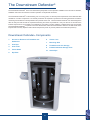
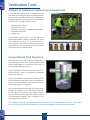
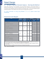
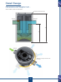
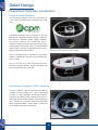
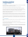
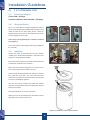
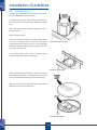
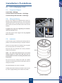
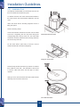
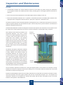
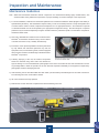
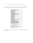
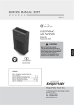
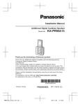
Downstream Defender® User Manual
Downstream Defender®
Advanced Hydrodynamic Vortex
Stormwater Treatment System
turning water around ...®
Advanced Vortex Technology;
Optimal Removal and Retention
The Stormwater Challenge
The Water Framework Directive (WFD) is the single
most important piece of water legislation to date.
It is
a mechanism to drive and achieve sustainable water
resources in Europe, to manage and control impacts at
source, and to collaborate for the long term.
It is an over-riding principle of the WFD that diffuse
pollution is managed at source to eliminate the discharge
of hazardous substances.
The Solution
Hydro International’s Downstream Defender® is the most
advanced hydrodynamic vortex separator available. The
Downstream Defender® has verified removal efficiencies
and is proven to prevent pollutant re-entrainment at high
flows.
2
The Need to Control Urban Runoff Quality
Urban runoff presents a number of challenges, in terms of both its quality and quantity. The natural environment has a
capacity to absorb and control the transfer rate of stormwater.
However, when this is replaced with impermeable surfaces (for example, roads and car parks), runoff rates can be increased
significantly. The volume of runoff from surface flows also increases and the response time of the catchment changes. This
can have a significant effect on the quantity and type of mobilised pollutants.
Traditionally, the focus of attention has tended to be on quantity control to alleviate the flooding problems associated with
increased runoff rates, with planning controls in place to limit the post-development runoff by providing storage or infiltration
capacity on site.
With the advent of the EU Water Framework Directive, it is becoming increasingly recognised that surface water runoff can
be a significant source of pollution. National, regional and local regulations and guidelines are starting to come together to
place increased emphasis on the control of Stormwater runoff quality.
An up to date guide on current legislation and guidance in the UK can be found on our website at:
http://www.hydro-international.biz/stormwater/legislation_and_guidlines.php
3
The Need to Control Urban Runoff Quality
The Importance of Sediment Control
Sediments play an important role in pollutant transport and dispersion. Sediment particles can adsorb charged chemical
pollutants including phosphates and pesticides and are associated with other pollutants such as heavy metals and polycyclic
aromatic hydrocarbons (PAHs). Sediment particles themselves are also a pollutant, tending to cloud water thereby blocking
out light and smothering stream beds. Sediment accumulation within sewer / drainage networks can also present difficulties
with blockages occurring which can contribute to surcharge of the system and surface flooding.
The Environmental Impact of Pollutant Re-entrainment
Pollutant re-entrainment is defined as the tendency for pollutants captured during a storm event to be re-suspended (or
re-entrained) and discharged by flows resulting from a subsequent storm event.
Rainfall patterns in the UK are notoriously unreliable and it is a generally accepted consequence of climate change, that
extreme storm events could become increasingly common. This is very important in practice as the environmental benefits
of the removal of pollutants at low flows is worthless if these pollutants are subject to re-entrainment during high flow storm
events.
Installation of a Downstream Defender® to protect an attenuation
pond from grits, silts and oils from the local road and domestic
surface runoff. The discharge from the pond is controlled by a
Hydro-Brake® Flow Control.
The completed, attenuation pond. The Downstream Defender®
manhole can be seen in the foreground.
4
The Downstream Defender®
The Downstream Defender® is the most advanced hydrodynamic vortex separator available for the removal of sediment,
floatables and oil from stormwater runoff and operates on simple fluid mechanics.
The Downstream Defender® is self-activating, has no moving parts, no external power requirement and is fabricated with
durable non-corrosive components. No manual procedures are required to operate the unit and maintenance is limited to
monitoring accumulations of stored pollutants and periodic clean-outs. The Downstream Defender® has been designed to
allow for easy and safe access for inspection/monitoring and clean-out procedures. Entry into the unit or removal of the
internal components is not necessary for maintenance, thus safety concerns related to confined-space-entry are avoided.
The Downstream Defender® is proven to be more efficient than other structural treatment devices in as little as half of the
footprint and is the only separator with internal components proven to prevent pollutant re-entrainment (washout).
Downstream Defender® Components
1.
Access for Removal of Floatables and
Sediments
2.
Inlet Pipe
3.
Inlet Chute
4.
Centre Shaft
5.
Dip Plate
6.
Centre Cone
7.
Benching Skirt
8.
Floatables and Oils Storage
9.
Isolated Sediment Storage Zone
10. Outlet Pipe
1
4
8
8
2
10
3
5
7
5
6
9
5
Applications and Advantages
Applications
Advantages
•
Removal of sediment, floatables and petroleum
•
Most efficient separator available.
products from surface water / stormwater flows.
•
Efficient over a wide range of flows.
•
Highway runoff.
•
Proven to prevent pollutant re-entrainment.
•
SUDS schemes.
•
Proven track record worldwide.
•
Soakaways and swales.
•
Small footprint.
•
Low Impact Development (LID) schemes.
•
Can be installed within the footprint of a carriageway
•
Wetland schemes.
/ embankment, avoiding the need for additional land
•
Basin and pond protection.
take.
•
Park & Ride schemes.
•
Watercourse and pond protection.
•
Industrial and commercial areas.
•
Vehicle maintenance washdown yards.
•
Quarry settlement ponds.
•
Can be used as an alternative to a sedimentary
forebay in a pond system.
•
Treatment of Park & Ride or commercial parking
schemes with no loss of parking spaces.
•
Can be retrofitted to industrial and commercial sites
without requiring extensive construction works.
New Features
•
Low system headloss.
•
No moving parts and no power requirement.
•
Consolidates maintenance to a single centralised
•
High flow internal bypass configuration.
•
Able to incorporate a change of pipe direction
location, helping to save time and costs on site
between 90° and 270° - allowing changes of
when compared to dispersed silt chambers or gully
direction without additional manholes.
pots.
•
Simplified installation procedure - all internal
•
Independently tested and verified performance.
components are fitted into the chamber before
•
Approved by regulatory agencies throughout the
world.
delivery. Installation is now similar to that of a
standard sectional manhole chamber. No confined
space entry is required.
Image shows a Downstream Defender® protecting a pond.
6
Case Study Applications
Shortwood Pond
A precious part of London’s remaining medieval common
land has been saved from the threat of pollution from nearby
highways with a simple solution, a 1.8 m Downstream
Defender®.
Runoff from nearby highways was threatening the
precarious wetland habitat of Shortwood Pond - home to
endangered species such as the Brown Galingale plant
and the Little Whirlpool Ramshorn snail. This habitat is
part of Staines Moor, located at the eastern end of Colne
Valley Park, which contains many Sites of Special Scientific
Interest.
The Downstream Defender® is ideally suited to protecting the
pond, because it separates out and retains the sediments.
The entrapped solids and sediments are not washed out
by high storm flows as they would be in conventional gully
pots. The hydrocarbons and floatable portions are also
retained.
Hop Oast Park & Ride Facility
The Hop Oast Park & Ride facility, designed in line with
Horsham District Council’s policy of providing sustainable
infrastructure and services, is used to reduce long stay
parking in the town centre. Adding further to its green
credentials, Horsham District Council installed a porous
pavement with a Hydro Stormwater Management System
to ensure controlled, unpolluted surface water discharge to
the local watercourse.
The surface water feeds into a Hydro Stormcell® modular
stormwater storage system which retains the excess
water and allows it to discharge under control via a 1.2 m
Downstream Defender® and a 111 mm Hydro-Brake® Flow
Control device, into a local watercourse.
Any silt within the system is carried through to the
Downstream Defender® where, due to its unique vortex
action, sediment settles out in the easy access sump and
hydrocarbon pollutants are separated into a collection
zone; both can be easily removed periodically.
7
How it Works
The Downstream Defender® internal components are designed to enhance the separation process by minimising headloss,
increasing efficiency and preventing re-entrainment of captured pollutants. Advanced hydrodynamic separation is achieved
by extending and stabilising the flow path, whilst isolating the captured pollutants in dedicated storage zones.
Contaminated stormwater entering the unit is directed
downwards and around the periphery of the chamber
(green arrows).
As flows increase, oils, litter and floatable material are initially
captured at the inlet and transferred to the oil storage zone
around the outer annulus of the chamber (brown area).
The oil storage zone is protected from the treatment flow
path and so prevents captured floatable materials being reentrained during peak flows.
As the flow continues to spiral around the periphery of the
chamber, low energy vortex motion directs settleable solids
into the base of the unit (yellow arrows). The internal
components isolate the base of the chamber from the
treatment flow path preventing re-entrainment of captured
solids.
The treated stormwater exits the chamber via the orientated
outlet pipe after ensuring the longest possible retention time
within the unit (light blue arrows).
Excess flows associated with extreme storm events bypass
both the vortex treatment chamber and also both the
sediment and oil storage zones. These excess flows pass
forward untreated via the orientated outlet pipe.
Flow Through the Downstream Defender®
Access to the base of the chamber for sediment removal can be achieved via the centre shaft (dark blue arrow) using
standard vacuum tanker equipment. The Downstream Defender® cover slab is fitted with access hole(s) to enable removal
of captured sediment and floatable materials.
Verification
Verified Treatment Performance
Hydro International has dedicated research and development facilities at both its UK and US offices, which allow for
extensive full and model scale testing of units. These tests along with comprehensive Computational Fluid Dynamics
(CFD) assessments and field monitoring programmes build up an accurate picture of pollutant removal and retention at
high and low flows.
These findings have been independently verified through 3rd party testing and certification programmes. A comprehensive
review of assessments and approvals can be obtained from Hydro International on request.
Hydro International has taken great care to ensure that the pollutants captured by the Downstream Defender® remain
within the unit even under extreme storm conditions. CFD analysis combined with independent model scale testing has
shown that the Downstream Defender® retains in excess of 99% of captured pollutants.
8
Verification Cont ...
Model Scale Assessment by Liverpool John Moores University
Model scale testing was carried out by Liverpool John Moores University’s Centre for Environmental Technology (LCET)
to compare a number of different configurations of Stormwater treatment devices. A particular focus of the study was on
the ability of the chambers to retain captured pollutants.
For each chamber configuration, sediment was allowed to settle on the base of the chamber. The chamber was then
subjected to moderate and high flow rates. Each test was filmed during the evaluation and the amount of sediment
washed out of the chamber was measured at the outlet.
This work concluded that chambers with an exposed sump (such as silt traps or simple gravity sedimentation devices)
are prone to pollutant re-entrainment during high flow conditions. These devices retained less than 1% of sediment.
The unique internal configuration of the Downstream Defender® meant that 99.7% of sediment was retained within the
chamber even under high flow conditions.
The images below show the start, middle and end frames from the video footage, comparing a Downstream Defender® to
a simple linear gravity sedimentation chamber.
Downstream
Defender® Chamber
Simple Linear
Chamber
Illustration of the importance of a protected sediment storage sump; the Downstream Defender® (top) is found to retain sediments, while
those stored in a simple linear chamber (bottom) are quickly flushed out.
9
Verification Cont ...
Analysis of Sediments Captured by Installed Units
A number of field monitoring trials on installed units have
been carried out, including a study by the University of Bristol
that compared the physical and chemical characteristics of
sediments captured at a number of units throughout the UK
and Ireland. The evaluated systems included:
• A motorway service station
• A park and ride car park
• A site during construction of a residential development
• A residential development
• An urban road
The sites were monitored over a 10 month period and
Sampling at South County, Dublin.
demonstrated effective capture of pollutants, with some
units recording as much as 3 m3 of sediment over the
monitoring period. The sediment captured was found to be
closely aligned in size and chemical content to what would
commonly be found in treatment ponds.
Samples collected from the six Downstream Defender® units.
Computational Fluid Dynamics
CFD techniques can be used to allow the assessment of
real engineering systems on a computer simulation basis
and are widely applied in the aerospace, automobile, oil
and other high technology industries.
Hydro International has pioneered the use of CFD in the
water-environment sector and developed considerable
experience in this area.
Over 20 configurations of Stormwater treatment system
have been analysed using CFD and have consistently been
found to have lower pollutant removal efficiencies than the
Downstream Defender® arrangement.
CFD also demonstrates that the sump of the Downstream
Defender® is shielded from the main treatment area with
low flow velocities experienced in the sediment storage
CFD plot of velocity magnitudes in the Downstream Defender®.
zone. This explains the superior pollutant retention capacity
of the Downstream Defender® when compared to other
Stormwater treatment devices.
Full details of testing and verification can be found in the ‘Downstream Defender® Overview
of the Technology and its Verification’ document available from Hydro International
10
Detail Design
System Performance
Removal efficiencies listed below are achieved for all flows up to and including the Treatment Flow Rate as shown in
Table 1 below.
• Greater than 80% of grits and silts down to a particle size of 150 microns with a minimum specific gravity of 2.65
• Greater than 80% of light oil with a maximum viscosity of 5.5 (to EN858-1).
Diameter of Unit
Treatment Flow Rate
(m)
(l/s)
Hydraulic Capacity
(l)
Oil Storage Capacity
Sediment Storage
(l)
Capacity
(m3)
1.2
21
120
270
0.7
1.8
51
300
1350
1.7
2.55
115
600
2500
3.8
3.0
160
750
4650
4.4
Table 1 Design Flows and Storage Volumes
Notes:i) Flow rates in excess of the Treatment Flow Rate are possible, but removal efficiencies may be reduced –
contact Hydro International for further information.
ii) Head loss at Treatment Flow is typically less than 150 mm.
iii) The Hydraulic Capacity is the maximum flow that can pass through the chamber without surcharge to the
upstream network.
1) Sizing for Storm Peak Flow - Preferred Method
The optimum design method is to select the unit size, such that the Treatment Flow (see Table 1 above) is close to the peak
flow of the maximum storm event likely to be conveyed by the system.
This design methodology maximises the treatment offered by the unit as all storms up to and including the peak flow of the
maximum storm event achieve removal efficiencies in excess of 80% for oils and grits.
Where the sewer system / drainage network includes latent capacity to provide a safety factor, excess / extreme flows
are still conveyed without restriction through the Downstream Defender® unit with a significant proportion of the flow being
treated.
For example, if the Stormwater pipe network has been designed to convey the 1 in 5 year storm without any surcharge to
the upstream network, then the Downstream Defender® should be sized for the peak flow likely to be experienced during
a 1 in 5 year storm of any duration.
2) Sizing for Water Quality Volume - An Alternative Method
The internal bypass configuration within the Downstream Defender® units, coupled with the unrivalled prevention of
pollutant re-entrainment, means that the Downstream Defender® can be designed for the Water Quality Volume without the
need for complex and potentially expensive diversion structures. Water Quality Volume is defined as treatment of 90% of
the average annual runoff.
Under Water Quality Volume design, the Downstream Defender® is sized such that the unit treatment flow is matched to the
peak flow associated with the Water Quality Volume storm event. This storm event caters for 90% of annual rainfall events
and is often referred to as the ‘First Flush’ and contains the majority of the pollutant load in the early stages of a given storm
event. It is generally considered that the first flush is equivalent to a rainfall depth of 10-20 mm.
As the sizing for Water Quality Volume design is based on annual return period storm events, the tendency will be for the
system to experience flows in excess of the treatment flow and operate under bypass conditions more frequently than for
Peak Storm Flow designs.
11
Detail Design
3) Sizing for Specific Pollutant Capture - Site Specific Method
Under certain circumstances it may be desirable to size the Downstream Defender® to target pollutant particles of a
defined size and specific gravity. For example, industrial sites where dust of a particular size and density is produced as
a by-product of the manufacturing process and escapes into the drainage system. The flow rates directed through the
Downstream Defender® can be determined such that removal of the target pollutant is optimised.
For further information on sizing using Methods 1), 2) or 3), please contact Hydro
International.
Dimensions and Weights
Unit
External
Diameter
of Unit (m)
Inlet &
Outlet Pipe
Diameter
(mm) iii)
Depth (m)
A
B
1.43
300
1.825
2.615
Component
Depth i)
Average
Weight
(kg)
0.135
412
2.615
3574
2.750
3986
0.160
1210
1.2 m Single Piece Unit with HD Cover Slab
HD Cover Slab ii)
Concrete Unit Including Base
Total
1.8 m Two Piece Unit with HD Cover Slab
HD Cover Slab ii)
3.003
7024
Concrete Unit - Base Section
1.375
4720
Total
4.035
12954
0.200
2766
3.000
9160
Concrete Unit - Top Section
2.16
450
2.500
3.875
2.55 m Two Piece Unit with HD Cover Slab
HD Cover Slab ii)
Concrete Unit - Top Section
2.85
600
2.950
4.750
Concrete Unit - Base Section
1.750
7687
Total
4.95
19613
0.200
4590
3.000
13410
Concrete Unit - Base Section
2.000
12142
Total
5.200
30142
3.0 m Two Piece Unit with HD Cover Slab
HD Cover Slab ii)
Concrete Unit - Top Section
3.35
750
3.125
5.000
Notes:
i) For sectional units, Base and Top section component depths are shown as the total height during transportation /
before assembly on site. The total unit depth is the depth of the assembled unit.
ii) Cover slabs are heavy duty, can take main road loadings and are supplied with a single or double 600 x 600 mm
access holes.
iii) Inlet and outlets are supplied with cast-in holes only. No stub pipes are provided.
Table 2 Dimensions and Weights
12
Detail Design
Dimensions and Weights Cont...
Refer to Table 2, Page 12 for dimensions.
Precast Concrete Cover Slab
Inlet Pipe
Outlet Pipe
B
A
Inlet Pipe
Outlet Pipe - Change of Direction from
90° to 270°
13
Detail Design
Downstream Defender® Construction
Precast Concrete Chambers
The Downstream Defender® units are manufactured as
a joint venture between Hydro International and CPM
Group.
Downstream Defender® units are supplied to site with
High Density Polyethylene (HDPE) internal components
fully fitted into reinforced precast concrete chambers.
The concrete chambers are manufactured using a
combined Portland cement and pulverised fuel ash (pfa),
manufactured to meet Design Class 4 as defined in BRE
Special Digest “Concrete in Aggressive Ground” Part 4
High Density Polyethylene (HDPE) internal components fully
fitted into a reinforced precast concrete chamber.
Design for Specific Precast Products.
The 1.2 m diameter units are supplied as a single piece
chamber, complete with base slab and a separate heavy
duty cover slab.
The 1.8, 2.55 and 3.0 m units are supplied to site as
sectional, two-piece chambers complete with base slab
and a separate heavy duty cover slab.
Cover slab being craned into position.
High Density Polyethylene (HDPE) Chambers
In certain conditions, it may not be practical to install the
complete concrete chamber unit.
Hydro International
are able to supply lightweight Downstream Defender®
units where the HDPE internal components are fitted to a
structurally reinforced HDPE chamber, which would comply
with a standard of construction approved by the British
Board of Agrément (BBA). Further details on these units
can be obtained from Hydro International.
HDPE internals fitted to a reinforced HDPE chamber.
14
Installation Guidelines
1) General Guidelines
1.1)Handling
The Downstream Defender® internal components are manufactured utilising highly durable high density polyethylene
(HDPE) and are pre-installed into a bespoke CPM concrete chamber.
Improper handling can result in damage to the components and/or the precast concrete chamber.
Failure to comply with the Hydro International / CPM Group handling and installation guidelines voids all warranties.
Upon delivery of Downstream Defender® components, inspect immediately for any damage sustained during transport. If
any discrepancies or problems are found notify the supplier prior to unloading to initiate corrective action.
Unloading of a damaged unit without notifying the supplier voids all warranties and releases liability of costs of repair or
replacement from Hydro International or CPM Group.
At all times during unloading and installation avoid any impacts to the units. Do not allow any of the components to be
dropped, rolled or pushed. At no time shall anyone step, stand or otherwise place unnecessary load on the components.
All components shall be lifted and moved using the designated lifting points giving firm and complete support to the unit.
The Downstream Defender® shall be installed as soon as possible following delivery. Pending installation any loose
components including universal head-links, sealant or seals shall be temporarily stored in an area protected from dirt and
impact.
1.2) Site Preparation
The chamber excavation shall be properly prepared in advance so that the unit may be installed as soon as practical upon
delivery.
The chamber excavation shall meet all minimum Health and Safety standards for construction.
The area of excavation should be carefully checked for any other services. The chamber should be positioned such that it
is at least 800 mm away from any other services.
A sub-base of compacted stone or concrete (depending on site conditions and considering the weight of the unit and
the contained water during usage) must be level and at the correct elevation prior to placing the Downstream Defender®
concrete chamber into the excavation.
15
Installation Guidelines
2) 1.2 m Diameter Unit
2.1) Component Weights
Cover Slab = 412 kgs
Concrete chamber with internals = 3574 kgs
2.2) Lifting and Moving
The 1.2 m unit is lifted as a single complete unit using a
pair of universal head-links (supplied with unit) which hook
under the head of the cast-in lifting anchor. These are
located opposite each other on the outside surface of the
unit and engage as shown right:
Chain sling to be supplied by the customer, minimum
leg length 3 m.
Cover slab requires a three legged chain sling (supplied by
the customer).
2.3) Installation
Off-load the ready to install precast concrete chamber
containing the Downstream Defender® components and
position it in the prepared excavation.
Ensure the inlet and outlet are correctly orientated and the
unit has been checked for line and level.
Make sure all the internal equipment is in place and no
tools or loose items have been left in the unit.
Place the Butyl sealant around the top surface of chamber
then install the cover slab.
The cover slab should be
orientated such that the access hole is above the inlet pipe
as shown in the diagram opposite.
The unit can now be carefully back filled with suitable
material to a level below the inlet and outlet pipes ready for
final pipe connection.
The inlet/outlet pipes can now be connected.
Setting-to-work - fill the chamber with clean water until the
discharge from the outlet commences.
Single Piece Installation & Cover Slab Orientation
16
Installation Guidelines
3) 1.8 Diameter Unit
3.1) Component Weights
Cover Slab = 1210 kgs
Concrete base with internals = 4720 kgs
Concrete body with internals = 7024 kgs
3.2) Lifting and Moving
The 1.8 m unit is lifted as two separate chamber sections
using a pair of universal head-links (supplied with the unit)
which hook under the head of the cast-in lifting anchor.
These are located opposite each other on the outside
surface of the base and body sections and engage as
shown opposite
Chain sling to be supplied by the customer, minimum
leg length 3 m.
Cover slab requires a three legged chain sling (supplied
by the customer).
3.3) Installation
Lower the base section containing the benching skirt into
position in the excavation ensuring to check line and level.
Position the seal provided and carefully lower and guide
the main body section onto the base section.
Ensure the inlet and outlet holes are correctly orientated.
Check for line and level.
NOTE: The centre shaft should still be in its raised
transport position to ensure the shaft and cone are
Body
protected while the sections are being lifted and moved
into position.
The unit can now be carefully back filled with suitable
material to a level below the inlet and outlet pipes ready for
final pipe connection.
The inlet/outlet pipes can now be connected.
Carefully back fill the remaining excavation so that only the
top 150 mm (approximately) of the chamber is visible.
Base
Two-piece Installation
17
Installation Guidelines
3.3) Installation Cont...
Once placed and back filled, the centre shaft and cone can
then be released and lowered into place.
To release and lower the centre shaft SAFE ACCESS to
the centre section of the Downstream Defender® must be
used.
Attach the centre shaft to the lifting equipment via the 2
lifting hole points.
Remove the fixing straps.
Lift the centre shaft a small amount to allow it to be rotated
Centre Shaft and Cone Detail
so that the 4 supporting ribs can drop down through the
corresponding slots in the top of the unit. The centre shaft
should then be slowly lowered so that the flange sits down
flat onto the top of the unit.
Fix the centre shaft in place using 6 off M10 x 50mm
stainless steel bolts and washers (supplied).
Fixings for Centre Shaft
Place the Butyl sealant around the top surface of chamber
then install the cover slab. The orientation of the access is
with the offset hole above the inlet pipe as shown right.
Setting-to-work. Fill the chamber with clean water until the
discharge from the outlet commences.
Cover Slab Orientation
18
Installation Guidelines
4) 2.55 m Diameter Unit
4.1) Component Weights
Cover Slab = 2766 kgs
Concrete base with internals = 7687 kgs
Concrete body with internals = 9160 kgs
4.2) Lifting and Moving
The 2.55 m unit is lifted as two separate pieces using 4 No.
M30 lifting loops (supplied with the unit). These are located
opposite each other on the upper surface of the base and
body sections and screw into inserts cast into the concrete
sections
4 legged Chain sling to be supplied by the customer,
minimum leg length 3.5 m.
Cover slab requires a three legged chain sling (supplied
by the customer).
4.3) Installation
Lower the base section containing the benching skirt into
position in the excavation ensuring to check line and level.
Position the seal provided and carefully lower and guide
the main body section onto the base section.
Ensure the inlet and outlet holes are correctly orientated.
Check for line and level.
Body
NOTE: The centre shaft should still be in its raised
transport position to ensure the shaft and cone are
protected while the sections are being lifted and moved
into position.
The unit can now be carefully back filled with suitable
material to a level below the inlet and outlet pipes ready for
final pipe connection.
The inlet/outlet pipes can now be connected.
Base
Carefully back fill the remaining excavation so that only the
top 150 mm (approximately) of the chamber are visible.
Two-piece Installation
19
Installation Guidelines
4.3) Installation Cont...
Once placed and back filled, the centre shaft and cone can
then be released and lowered into place.
To release and lower the centre shaft SAFE ACCESS to
the centre section of the Downstream Defender® must be
used.
Attach the centre shaft to the lifting equipment via the 2
lifting hole points.
Remove the fixing straps.
Lift the centre shaft a small amount to allow it to be rotated
Centre Shaft and Cone Detail
so that the 4 supporting ribs can drop down through the
corresponding slots in the top of the unit. The centre shaft
should then be slowly lowered so that the flange sits down
flat onto the top of the unit.
Fix the centre shaft in place using 6 off M10 x 50 mm
stainless steel bolts and washers (supplied).
Fixings for Centre Shaft
Place the Butyl sealant around the top surface of chamber
then install the cover slab. The orientation of the access
is with the offset hole above the inlet pipe as shown
opposite.
Setting-to-work. Fill the chamber with clean water until the
discharge from the outlet commences.
Cover Slab Orientation
20
Installation Guidelines
5) 3.0 m Diameter Unit
5.1) Component Weights
Cover Slab = 4590 kgs
Concrete base with internals = 12142 kgs
Concrete body with internals = 13410 kgs
5.2) Lifting and Moving
The 3.0 m unit is lifted as two separate pieces using 4 No.
M30 lifting loops (supplied with the unit). These are located
opposite each other on the upper surface of the base and
body sections and screw into inserts cast into the concrete
sections
4 legged Chain sling to be supplied by the customer,
minimum leg length 4.0 m.
Cover slab requires a three legged chain sling (supplied
by the customer).
5.3) Installation
Lower the base section containing the benching skirt into
position in the excavation ensuring to check line and level.
Position the seal provided and carefully lower and guide
the main body section onto the base section.
Ensure the inlet and outlet holes are correctly orientated.
Body
Check for line and level.
NOTE: The centre shaft should still be in its raised
transport position to ensure the shaft and cone are
protected while the sections are being lifted and moved
into position.
The unit can now be carefully back filled with suitable
material to a level below the inlet and outlet pipes ready for
final pipe connection.
The inlet/outlet pipes can now be connected.
Base
Carefully back fill the remaining excavation so that only the
top 150 mm (approximately) of the chamber are visible.
Two-piece Installation
21
Installation Guidelines
5.3) Installation Cont...
Once placed and back filled, the centre shaft and cone can
then be released and lowered into place.
To release and lower the centre shaft SAFE ACCESS to
the centre section of the Downstream Defender® must be
used.
Attach the centre shaft to the lifting equipment via the 2
lifting hole points.
Remove the fixing straps.
Lift the centre shaft a small amount to allow it to be rotated
so that the 4 supporting ribs can drop down through the
Centre Shaft and Cone Detail
corresponding slots in the top of the unit. The centre shaft
should then be slowly lowered so that the flange sits down
flat onto the top of the unit.
Fix the centre shaft in place using 6 off M10 x 50 mm
stainless steel bolts and washers (supplied).
Fixings for Centre Shaft
Place the Butyl sealant around the top surface of chamber
then install the cover slab. The orientation of the access
is with the offset hole above the inlet pipe as shown
opposite.
Setting-to-work. Fill the chamber with clean water until the
discharge from the outlet commences.
Cover Slab Orientation
22
Inspection and Maintenance
Notes:
1. Contaminated stormwater can contain substances harmful to human health. Any person carrying out maintenance
on the equipment should wear suitable protective clothing, including gloves. Good hygiene practice should also be
observed.
2. When covers are removed precautions must be taken against the risk of falling in to the unit.
3. Where the Downstream Defender® and / or upstream / downstream structures are situated within trafficked areas,
appropriate traffic management measures must be in place prior to inspection / maintenance work.
The internal components of the Downstream Defender® are designed not only to enhance the removal process, but also to
isolate the captured pollutants from the treatment flow path. This has been proven to prevent washout / re-entrainment of
pollutants during high intensity storms.
The Downstream Defender® unit has been designed so that all normal inspection and maintenance can be carried out from
the surface and no internal parts need to be moved or removed. Therefore no confined space entry is required.
600 x 600mm access holes are provided on the
Downstream Defender® cover slab to enable
Floatables
Storage Zone
access to the captured pollutants storage zones.
A central access point provides access via the
central shaft of the chamber to the sediment
storage zone at the base of the chamber. On
smaller units this central access point also allows
access to the floatables storage zone. For larger
units a secondary access point is provided over
the inlet to allow access to the inlet and floatables
storage zone.
An effective, site-specific maintenance schedule
should be developed to ensure that the stormwater
is being collected and directed through the
Downstream Defender® unit correctly and also
to ensure that the volume of captured pollutants
does not exceed the storage capacity within the
unit. Whilst the maintenance required for each
installation will vary depending on the local site
conditions (ie. catchment area, pollutant loadings,
storm frequency and intensity, etc.) the following
Sediment
Storage Zone
general guidelines can be used during development
of the site-specific maintenance schedule.
The unit should be inspected at site hand-over / during the adoption phase to ensure that the unit has been correctly
installed, that all internal components are free from damage, that no construction debris has entered the unit and that
stormwater can freely flow through the unit.
Inspections should initially be carried out at six monthly intervals and an annual clean-out should be conducted to monitor
and remove pollutants and ensure proper operation and free flow of stormwater through the unit. The inspection and
maintenance intervals can be adjusted once sufficient site specific data has been accumulated to give an accurate
indication of the operation of the installed unit.
23
Inspection and Maintenance
Typical Maintenance Schedule
Activity
Inspection
Frequency
Inspect for evidence of poor operation.
At site hand-over then every six months.
Inspect sediment and floatables accumulation
rates and establish removal frequencies.
Regularly during first year of operation, then
every six months or as required.
Regular
Maintenance
Sediment removal.
Annual or as required.
Floatables removal.
Annual or as required.
Remedial Action
Sediment removal.
Following spill in drained area.
Floatables removal.
Following spill in drained area.
It is highly recommended that accurate inspection and maintenance logs are compiled and retained on record. The
maintenance logs should include observations (and ideally photographs) of the unit as well as the volume of sediment, oils
and floatables removed during each maintenance visit.
Inspection Guidelines
1) Inspection visits should be coordinated with the property owner, facilities manager or assigned contact person to
ensure that access to the Downstream Defender® chamber and the manholes immediately upstream and downstream
of the unit is possible.
2) The upstream and downstream manholes should be inspected to ensure that debris is not preventing Stormwater
from being collected in the drainage system and directed into the Downstream Defender® unit. Any debris should be
removed and disposed of according to local guidance / regulations.
3) The Downstream Defender® unit should be inspected for accumulation of captured pollutants. The inlet of the
Downstream Defender® should be inspected to ensure that there is no excessive build up of captured material. Free
flow of water through the unit should be verified.
4) Inspection records should be completed and retained for each visit.
Depth Gauge Measurement of Captured Sediment
24
Inspection and Maintenance
Maintenance Guidelines
Note: Whilst the Downstream Defender® internal components are manufactured utilising highly durable HDPE, care
should be taken during maintenance operations. Improper handling can result in damage to the components.
1) For most installations, sediment and associated pollutants are considered Hazardous Waste (England and Wales) or
Special Waste (Scotland). This classification imposes a Duty of Care on the waste producer to notify the Regulator and
to ensure that the waste is stored, transported and disposed of in an appropriate manner. All movements of Special
or Hazardous Waste must be accompanied by the appropriate consignment note(s). Chemical analysis of captured
pollutants may be beneficial especially for higher risk sites where the potential for spills or accumulation of Special or
Hazardous Waste exists.
2) Removal of floatables and sediment from the Downstream
Defender® unit should be carried out using a vacuum tanker
or similar and carried out by a suitably licensed body.
3) Evacuation of the captured pollutants should be performed
by fully trained and authorised personnel only and the
equipment used, such as cleaning hoses, must be equipped
with protective nozzles to avoid damage to the Downstream
Defender® components.
4) Following emptying of the unit, the internal components
Cleaning of Internal Components and Pollutant Removal
via Vacuum Tanker Hose.
should be cleansed using clean water and checked for
signs of damage. It is recommended that a photographic record of the unit is taken at each visit and retained on record.
Any damage liable to affect the operation of the unit should be reported immediately to the supplier accompanied by
photographic evidence identifying the fault.
5) After cleansing the unit should be filled with clean water (not black water) until discharge from the outlet commences.
Free discharge from the unit should be verified.
6) All covers should be securely replaced.
7) Maintenance records should be completed and retained following each visit.
25
Integrated Stormwater Systems
As with all Hydro’s Stormwater Systems, Downstream Defender® Separators can be integrated with or used in place of
what are becoming increasingly known as ‘soft’ SUDS solutions (such as swales, ponds, lagoons etc).
Hydro International is committed to providing integrated products and solutions that support Sustainable Drainage
Systems.
In addition to Downstream Defender®, Hydro International also provides other solutions for commercial developers and
designers. Combined, our products provide comprehensive sustainable solutions to meet the most stringent regulations.
Our Stormwater Product Portfolio includes:
Stormbloc® Stormwater Storage and
Infiltration System
Hydro-Brake® Flow Control
A block type structure with
control that provides superior
a patented maintenance
hydraulic performance over
/ inspection tunnel for
conventional flow regulators with
providing underground
patented features that reduce
surface water infiltration and
maintenance requirements. Our
storage systems.
STH range of Hydro-Brake®s is
A self-activating vortex flow
the only BBA Approved vortex
flow control.
®
Stormbloc Inspect
A stackable modular access
unit offering unrivalled
Downstream Defender®
accessibility to any
An advanced hydrodynamic
STH Range of
Hydro-Brake® Flow Controls
vortex separator designed to
®
Stormbloc installation.
remove sediment, floatables
and associated pollutants from
Stormcell® and Stormcell® Lite
Stormwater Storage Systems
stormwater.
A low cost underground storage
Up-Flo™ Filter
system suitable for installation
A high-rate modular stormwater
beneath roads, car parks and
treatment filter featuring a patented
amenity areas. Stormcell® is
upward flow path with a unique
installed utilising a patented
pipework system which
Drain Down design. The filter
prevents the entry of silts and
targets a wide range of pollutants
including floatable debris, fine
grits into the storage volume.
sediments, nutrients, metals, oils
StormBank® Rainwater Harvester
and grease, organics and bacteria.
StormBank® can be used
Hydro Filterra® Bioretention System
to replace treated mains
An enhanced biofiltration system
water for use in toilets,
that packages indigenous
garden and outdoor use.
vegetation with engineered soils
StormBank® Pro for large
for high levels of stormwater
commercial developments
treatment. The small footprint
and StormBank® Garden
makes it ideal for both new
(exclusively for garden
developments and retrofit to
watering) are also available.
existing ones.
Visit: www.savetherain.info
26
For more than
30 years Hydro
International’s
commitment to
product research and
development has set
industry standards.
With a proven track
record Downstream
Defender® is the
setting the standard
technology driving
design
stormwater treatment
separator you can
trust.
Our History
Our Advantage
Hydro International was formed in 1980 to promote
Hydro International is committed to a policy of continuous
the hydrodynamic separator and vortex flow control
product development. Our understanding of integrated
water management ensures that sustainable site-specific
technology around the world.
solutions set the standards.
We have also been promoting source control and what
are now commonly known as Sustainable Drainage
To ensure that research outputs are of the highest
Systems (SUDS) for well over a decade.
quality, Hydro International utilises state-of-the-art testing
technology and analytical techniques both in-house and
through independent centres of excellence.
Contact us Today
If you require assistance with design or would like further information on any of our other stormwater products, call us at
01275 337977 or visit us on-line at www.hydro-international.biz.
We look forward to working with you.
27
w w w.h y d r o- i nt er nat i onal . bi z
Hydro International
Stormwater
Shearwater House • Clevedon Hall Estate
Victoria Road • Clevedon • BS21 7RD
Tel: 01275 878371 • Fax: 01275 874979
United Kingdom
United States
Ireland
Hydro International
Water & Wastewater
Prickwillow Road
Ely
Cambridgeshire
CB7 4TX
Hydro International
Stormwater & Wet Weather
94 Hutchins Drive
Portland, ME 04102
Hydro International
Wastewater
2925 Aloclek Drive
Suite 140
Hillsboro, OR 97124
HRD Technologies
Tootenhill House
Rathcoole
Co Dublin
Tel: +44 (0) 1353 645700
Fax: +44 (0) 1353 645702
Tel: +1 (207) 756 6200
Fax: +1 (207) 756 6212
Tel: +1 (503) 615 8130
Fax: +1 (503) 615 2906
Tel: +353 (0) 1 4013964
Fax: +353 (0) 1 4013978
abcdef
abcdef
Certificate No. 4004540
Seacourt Logo Here
© 2010 Hydro International. All rights reserved.
DDUM A/1110
Certificate No. 0961366