1
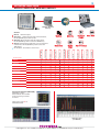
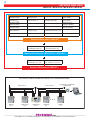
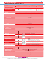
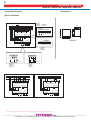
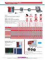
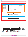
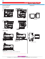
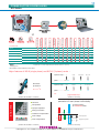
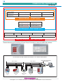
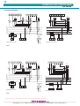
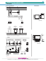
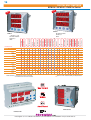
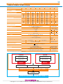
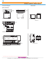
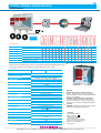
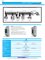
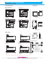
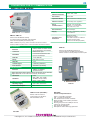
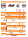
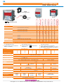
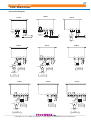
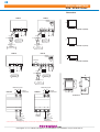
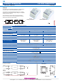
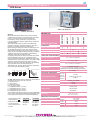
Mätinstrument
HARMONIC ANALYSERS
MPR63-10
Sid. 3
Sid. 16
DIGITAL ENERGY COUNTER
ES-32L
MPR53CS-96
Sid. 20
EPM-06C-DIN
Sid. 20
ES-25N
COS METER
NETWORK ANALYSERS
MPR53S-DIN
Sid. 7
REACTIVE POWER
CONTROLLERS
RG-8BS
Sid. 11
POWER & ENERGYMETERS
POWER & ENERGYMETERS
EPR-04S-96
EPR-04S-DIN
Sid. 19
MPR-SW / REMOTE
MONITORING SOFTWARE
MPR-SW
Sid. 22
FREQUENCY METER
Sid. 19
VOLTMETERS
EVM-3S & EVM-R3C
Sid. 24
VOLTAGE & CURRENT
TRANSDUCERS
CT-25
EPM-4P & EPM-R4D
Sid. 26
OVERCURRENT
PROTECTION RELAYS
CKR-93T
Sid. 16
DIGITAL ENERGY COUNTER
AMMETERS
ENT
Sid. 7
MULTIMETERS
MULTIMETERS
EPM-06CS-96
NETWORK ANALYSERS
3
1
Sid. 31
ECR-3-96
Sid. 29
CT-25-L.V.CURRENT
TRANSFORMERS
Sid. 35
EFC-3-72
Sid. 29
L.V. POWER
CAPACITORS
TV-111
Sid. 30
L.V. CURRENT
TRANSFORMERS
Sid. 34
Industrigatan 4, 212 14 Malmö Tel 040-38 15 70 Fax 040-38 15 78. Webbutik: www.proswede-elab.se
Sid. 35
2
CERTIFICATES & APPROVALS
Vi förbehåller oss rätten till ändringar i denna katalog utan särskilt meddelande
Industrigatan 4, 212 14 Malmö Tel 040-38 15 70 Fax 040-38 15 78. Webbutik: www.proswede-elab.se
3
NETWORK ANALYSER
MPR-50 / MPR-52S / MPR-60S / MPR-63
Modbus / Ethernet
Gateway
Memory
Alarm Contact
0(4)-20mA
Digital
Input
0(2)-10V
Harmonics
RS-485 Comm.
Analogue
Output
Energy Pulse Output
Memory
Digital Input
Modbus
Alarm Contact
I neutral
2-31th Harmonics
Product Code
% THD I, THD V
MPR-50 : Network Analyser.
MPR-52S-10 : Network Analyser with THD measurement,
RS-485 (MODBUS) and Alarm Contact.
MPR-60S: Network Analyser with THD measurement,
RS-485 (MODBUS), Alarm Contact and 1MB Memory.
MPR-63: Network Analyser with THD, up to 31th Harmonics
measurement, RS-485 (MODBUS), Alarm Contact and
1MB Memory.
IEC 61000-6-2, IEC 61000-6-4, IEC 61010-1
MD
mA
MPR-50
MPR-52S-10
MPR-60S
MPR-60S-10
MPR-60S-20
MPR-60S-21
MPR-60S-40
MPR-60S-41
MPR-63
MPR-63-10
MPR-63-20
MPR-63-21
MPR-63-40
MPR-63-41
PC Interface Software (MPR-SW) :
MPR-SW is a graphic
based software, which enables
remote monitoring via internet
or intranet.
Please refer to page 20 for
MPR-SW Software.
Front Panel View
Harmonics View
(for MPR-63)
Industrigatan 4, 212 14 Malmö Tel 040-38 15 70 Fax 040-38 15 78. Webbutik: www.proswede-elab.se
Max. Dem
Demand
Real Time Clock
General
LCD Display
MEMORY
MPR-63
4
NETWORK ANALYSER
MPR-50 / MPR-52S / MPR-60S / MPR-63
Phase - Neutral
Voltages (VLN)
Phase - Phase
Voltages (VLL)
Average Phase Neutral Voltage
Average Phase Phase Voltage
Neutral Current
Active Power (P)
Active Energy Import (kWh)
Total Current ( I)
Reactive Power (Q)
Active Energy Export (kWh)
Power Factor (P.F)
Apparent Power (S)
Cos
Total Active Power ( P)
Max. Demand
Frequency (Hz)
Total Reactive Power ( Q)
Phase Currents (I)
Max / Min. Values
Total Apparent Power ( S)
Reactive Energy Capacitive (kVArh)
Reactive Energy Inductive (kVArh)
Measured Parameters ( MPR-50 )
Total Harmonic Distortion
for Voltage (THD V %)
Total Harmonic Distortion
for Current (THD I %)
Measured Parameters ( MPR-52S-10 / MPR-60S )
Individual Harmonics
for Voltage - up to 31th
Individual Harmonics
for Current - up to 31th
Measured Parameters ( MPR-63 )
247 DEVICES CAN BE CONNECTED SERIALLY BY USING REPEATERS.
MAX. 1200 mt.
MAX. 1200 mt.
...
RPT-01
MPR-63
#247
MPR-52S-10
#246
REPEATER
RPT-1
RS485/USB or ETHERNET
CONVERTER
MPR-60S
#31
MPR-63
#1
Industrigatan 4, 212 14 Malmö Tel 040-38 15 70 Fax 040-38 15 78. Webbutik: www.proswede-elab.se
5
NETWORK ANALYSER
MPR-50 / MPR-52S / MPR-60S / MPR-63
MODEL
SPECIFICATIONS
MPR50
MPR-63
MPR60S
MPR52S-10
Electrical Parameters
Operating Voltage
Network Type
2 - 31th separately
voltage & current
THD V%, THD I%
THD V%, THD I%
Harmonic Measurement
85-265V AC / DC ; 50/60 Hz
3-phase / 4-wire (Star) ; 3-phase / 3-wire (Delta) ; 3-phase / 3-wire (Aron)
Accuracy
Voltage
0,5 % ± 2 digit
Current
Frequency
0,5 % ± 2 digit
0,1 % ± 2 digit
1 % ± 2 digit
Active Power
Reactive Power
Current Transformer Ratio
1...2 000 (programmable)
Voltage Transformer Ratio
1,0…4 000 (programmable)
2 % ± 2 digit
Measurement input
Voltage
1,0 - 300,0 V AC (P-N), 2,0 - 500,0 V AC (P-P)
Current
5 mA - 5,5 A
Measurement Ranges
1,0 - 400,0 kV
Voltage
5 mA - 10 000 A
45,0 - 65,0 Hz
Current
Frequency
0 - 4 000 M (W, VAr, VA)
Power
Energy
Power Consumption
Burden
Demand Time
0 - 99 999 999 kWh, kVArh
< 6 VA
< 1 VA (Current burden), < 0,5 VA (Voltage burden)
15 min. (Programmable via MPR-SW)
Communication Interface
MODBUS RTU (RS-485)
Baud Rate / Adress / Parity
Switch Period
Operation Current
Operation Voltage
Analogue Output (optional)
MPR6x-20
MPR6x-10,
Real Time / Latch
50 msec. (Min.)
5...24VDC, 30VDC (Max.)
Output 3 :
Active Energy Pulse Output (1 kWh...50 MWh / pulse)
Output 4 :
Reactive Energy Pulse Output (1 kVArh...50 MVArh / pulse)
41
Energy Pulse Output
Output 3 / Output 4 : 2 Digital Inputs
MPR-60S-21 /
Operation Voltage
MPR63-21 / 41,
Input Pulse Width
for MPR-52S- 10,
Functions
Output 1 / Output 2 : 2 NO relays , 5A, 1250 VA (resistive)
MPR63, MPR-60S,
Alarm Contact Output
Digital Input
1 200 - 38 400 bps / 1 - 247 / None, Odd, Even
Min. 1 sec.
(100...2500 msec. pulse width)
Max. 50 mA
5...24V DC, max. 30V DC
(0)4-20mA (MPR6x-40, MPR6x-41) / (0)2-10V (MPR6x-20, MPR6x-21)
Display
3,6” LCD with Backlight, 12 mm Height
Data Logging
Selectable 28 parameters with Time Stamp (15 000 records)
Memory
1 MB Internal Memory
Mechanical Parameters
Equipment Protection
Degree of Protection
Ambient Operating Temperature
Connection / Installation
Dimensions
Weight / each
Quantity in 1 package
Double Insulation (
) Measurement Category III
IP40 (front panel), IP54 (Optional)
-5oC, +55oC
Terminal / Flush-mounting with rear terminals
96x96 mm (PR19)
0,9 kg
8 pcs
Industrigatan 4, 212 14 Malmö Tel 040-38 15 70 Fax 040-38 15 78. Webbutik: www.proswede-elab.se
6
NETWORK ANALYSER
MPR-50 / MPR-52S / MPR-60S / MPR-63
Dimensions
Connection Diagram
(PR19- 96x96mm)
Valid for;
MPR63-20
MPR63-21
3 Phase with neutral connection
L
K
L
k
l
l
L3
K
2
1
Analogue
Output RS-485
l
6
5
4
3
L1
79.3
70
L
k
N
MPR63-40,
MPR63-41
L2
11 12 13 14 15 16
L3
Current Measurement Inputs
GND A
8
L1
9
L2
11 12 13 14 15 16
10
L3
TR
Analogue
Output RS-485
Voltage Measurement Inputs
7
B
90
k
L2
96
K
L1
N
GND A
B
TR
96
1. Relay 1
3. Input 1
2. Relay 2
19 20
25
26
Input 2
L1
N
+
_
Input 1
RS-485
11 12 13 14 15 16
External
Supply
4. Input 2
21 22 23 24
1A
17 18
Max:30VDC
GND A
B
TYPE PR 19
TR
Valid for;
MPR63
MPR63-10
4. Input 2
3. Pulse A 4.Pulse R
21 22 23 24
Input 2
+
_
Pulse R
Pulse A
Max:30VDC
Max:30VDC
Valid for;
MPR63-10
MPR63-20
MPR63-40
Valid for;
MPR63
MPR63-21
MPR63-41
3 Phase with neutral connection
3 Phase without neutral Aron connection.
K
K
L
k
L2
K
l
L
k
L3
L1
K
L
k
l
K
L3
L1
1. Relay 1
L3
GND A
2. Relay 2
3. PulseA 4. PulseR
19 20
21 22 23 24
Input 2
B
8
Max:30VDC
10
9
L2
L3
11 12 13 14 15 16
N
GND A
TR
External
Supply
25
+
_
Input 1
7
L1
N
Analogue
Output RS-485
Voltage Measurement Inputs
11 12 13 14 15 16
1A
17 18
L2
6
L3
Current Measurement Inputs
Analogue
Output RS-485
10
9
L2
1. Relay 1
17 18
26
2. Relay 2
3. PulseA 4. PulseR
19 20
21 22 23 24
L1
N
Input 1
Input 2
B
TR
External
Supply
25
1A
8
l
5
4
3
L1
Current Measurement Inputs
7
2
1
L3
Voltage Measurement Inputs
L
k
6
5
4
L2
l
k
L2
l
3
2
1
L
L1
L1
+
_
Input 1
21 22 23 24
+
_
3.Input 1
Max:30VDC
26
L1
N
Connection diagrams are given for reference. Please always check the latest user manual given with product or download from www.entes.com.tr.
Industrigatan 4, 212 14 Malmö Tel 040-38 15 70 Fax 040-38 15 78. Webbutik: www.proswede-elab.se
7
DIGITAL NETWORK ANALYSER
MPR-53 / EPM-07 Series
new
Modbus / Ethernet
Gateway
MPR-53CS-96
kWh
MD
General
kVArh
01101001
016
Pulse
Counter
Pulse Counter
Digital Hour Counter
Digital Hour
Counter
CT-25 (210A)
.../5A
Alarm
Contact
6 Different Energy
Calculation Methods
Dual Energy Meter
Digital
Input
Energy Pulse Output
Digital Input
Neutral Current
% THD V
% THD I
Pulse
Output
RS-485 Comm.
Modbus Harmonics
EPM-07 : Network Analyser.
EPM-07S : Network Analyser with RS-485 (MODBUS).
MPR-53 : Network Analyser with THD measurement.
MPR-53S : Network Analyser with THD measurement and RS-485 (MODBUS).
MPR-53CS: Network Analyser with THD measurement, RS-485, Pulse Counter,
Digital Hour Counter, Alarm Contact
IEC 61000-6-2, IEC 61000-6-4, IEC 61010-1
Product Code
Max.
Demand
Alarm Contact
MPR-53 / EPM-07 series measures many parameters of an
electric network. More than 50 parameters are displayed.
EPM-07 -96
EPM-07 -DIN
EPM-07S -96
EPM-07S -DIN
MPR-53 -96
MPR-53 -DIN
MPR-53S -96
MPR-53CS -96 (new)
MPR-53S -DIN
MPR-53CS -DIN (new)
MPR-53S -DIN-CT25
EPM-07S -DIN-CT-25
Optional - Min. Order Quantity is 200pcs/devic
PC Interface Software (MPR-SW) :
MPR-SW is a graphic
based software, which enables
remote monitoring via intranet or
internet.
popular in
small cabinets!
Please refer to page 20 for
MPR-SW Software.
MPR-53S-DIN-CT25
CT-25 is a Current Transformer, which is used together with
MPR-53S-DIN-CT25 model.
It is a unique solution, which replaces conventional type CTs
up to 120A.
Industrigatan 4, 212 14 Malmö Tel 040-38 15 70 Fax 040-38 15 78. Webbutik: www.proswede-elab.se
8
DIGITAL NETWORK ANALYSER
MPR-53 / EPM-07 Series
Phase - Neutral
Voltages (VLN)
Phase - Phase
Voltages (VLL)
Reactive Energy Capacitive (kVArh)
Reactive Energy Inductive (kVArh)
Total Current ( I)
Apparent Power (S)
Power Factor (P.F)
Total Active Power ( P)
Cos
Total Reactive Power ( Q) Max. Demand
Frequency (Hz)
Total Apparent Power ( S) Max / Min. Values
Phase Currents (I)
Active Power (P)
Active Energy Import (kWh)
Neutral Current
Reactive Power (Q)
Active Energy Export (kWh)
Average Phase Neutral Voltage
Average Phase Phase Voltage
Measured Parameters ( EPM-07 / 07S )
Total Harmonic Distortion
for Voltage (THD V %)
Total Harmonic Distortion
for Current (THD I %)
Measured Parameters ( MPR-53 / MPR-53S )
Digital Hourmeters
Digital Pulse (Count)
Measured Parameters ( MPR-53CS )
247 DEVICES CAN BE CONNECTED SERIALLY BY USING REPEATERS
MAX. 1200 mt.
MAX. 1200 mt.
...
RPT-01
MPR53CS-96
#247
EPM-07S
#246
REPEATER
RPT-1
RS485/USB or ETHERNET
CONVERTER
MPR-63
#31
MPR53S-DIN
#1
Industrigatan 4, 212 14 Malmö Tel 040-38 15 70 Fax 040-38 15 78. Webbutik: www.proswede-elab.se
9
DIGITAL NETWORK ANALYSER
MPR-53 / EPM-07 Series
(new)
MODEL
SPECIFICATIONS
EPM-07
EPM-07S
MPR-53
MPR-53S
MPR-53C
Electrical Parameters
Operating Voltage
Network Type
Accuracy
Current Transformer Ratio
Voltage Transformer Ratio
Measurement input
Voltage
Current
Measurement Ranges
THD
Voltage
Current
Frequency
Power Factor
Power
Energy
Power Consumption
Burden
Demand Time
Communication Interface
Baud Rate
Address
Parity
Alarm Contact Output
Digital Output
Digital Hourmeter
Digital Input
Input Pulse Width
Operation Voltage
Energy Pulse Output
Switch Period
Operation Current
Operation Voltage
Display
110VAC* / 230 V AC ±10%; 45 - 65 Hz
3-phase / 4-wire (Star), 3-phase / 3-wire (Delta), 3-phase / 3-wire (Aron)
1% ±1 digit
1…2000 (programmable)
0,1…4000,0 (programmable)
10 - 300 V AC (L-N), 10 - 500 V AC (L-L)
50 mA - 5,5 A
0-99.9 %
-
10 - 500 V (direct), 10 - 400 kV (with voltage transformer)
50 mA - 5,5 A (direct), 50 mA - 10.000 A (with current transformer)
20 - 90 Hz
4 quadrant
0 - 215 M (W, VAr, VA)
0 - 99 999 999 999,9 kWh, kVArh
< 4 VA
< 1 VA (Current burden), < 0,5 VA (Voltage burden)
1 - 60 min. (programmable)
MODBUS RTU (RS-485) [for EPM-07S & MPR-53S]
1200 - 38400 bps
1 - 247
No, odd, even
Output 1/2 : 2 NO relays, 5A, 1250 VA (resistive) [for MPR-53CS]
Output 3/4 : Mentioned on Front Panel [for MPR-53CS]
Output 5/6/7/8 : (Virtual Outputs) Mentioned in Register Table
3 Hourmeters (HH HH HH HH.HH) :
Total Hours (non-resettable)
[for MPR-53CS]
Run Hours (resettable)
Setpoint Hours (resettable for 16 setpoints)
2 Digital Inputs
80 msec. (Min.), (100msec. period)
12...48 V AC / DC
NPN Transistor
Min. 1,6 sec. (400 msec. pulse width)
Max. 50 mA
5…24 V DC, max. 30 V DC
Red LED ; 10 mm Height
Mechanical Parameters
Equipment Protection
Ambient Operating Temperature
Degree of Protection
Connection / Installation
Dimensions
Weight / each
Quantity in 1 package
Double Insulation (
), Measurement Category III
o
o
-5 C, +55 C
IP40 (front panel)
Terminal / Flush-mounting with rear terminals
96x96 mm (PR19**), DIN6 (PK26**)
0,6 kg (PR19) ; 0,6 kg (DIN6)
12 pcs (PR19), 12 pcs (DIN6)
* 110 V AC, 60Hz Supplied devices are custom manufactured by order
Industrigatan 4, 212 14 Malmö Tel 040-38 15 70 Fax 040-38 15 78. Webbutik: www.proswede-elab.se
10
DIGITAL NETWORK ANALYSER
MPR-53 / EPM-07 Series
Dimensions
Connection Diagram
(PR 19- 96x96mm)
MPR-53S
MPR-53S
90
96
79.3
70
96
TYPE PR 19
Output Relay
MPR-53S
(PK 26 - DIN6)
10.8 30.1 7.6
9.5
60.6
45.0
90.0
MPR-53S
8.5
14.0
26.5 21.5
53.0
58.0
106.0
10.0
MPR-53S
TYPE DIN / PK 26
MPR-53S
* RS-485 terminals are standart for Epm-07 and MPR-53S
Connection diagrams are given for reference. Please always check the latest user manual given with product or download from www.entes.com.tr.
Industrigatan 4, 212 14 Malmö Tel 040-38 15 70 Fax 040-38 15 78. Webbutik: www.proswede-elab.se
11
POWER FACTOR CONTROLLERS
RG Series
Pcs / Carton
Over Heat Protection
RS-485 Communication
Password Protection
Auto Setup
Dual Target cos-phi
Overheat Protection
THD Protection
3-phase
Capacitor Use
Single-phase
C a pa c i to r Us e
Product Code
Max. Steps
0
no >>> C
3-phase / 3 CTs
Harmonics
Single Phase / 1 CT
Modbus
Smart Switching
new
RG-6T
6
4
RG-8T
8
4
RG-12T
12
4
8
12
RG-8B
-96
RG-8BS
(new)
-96
(new)
8
12
RG3-12C
12
4
RG3-12CS
12
4
Discharge Unit
DU-3
Required for L.V. Power Capacitors up to 50 kVAr, 400V AC – 415V AC
20
Discharge Unit
IEC 61000-6-2, IEC 61000-6-4, IEC 61010-1
Major features of RG-B (single phase) and RG3-C (3-phase) series :
capacitor steps...... 1
phase.............. L1-L2-L3
2-3-4
5-6-7-8-9
10-11-12
L1
L2
L3
4-5-6-7
8
9-10-11-12
L1
L2
L3
Overheat
capacitor steps......1-2-3
protection
no >>> oC
phase.............. L1-L2-L3
etc...
programmable steps
(for RG-B / BS and RG3-C / CS series)
Harmonic
Compensation of each phase individually
A unique solution
for unbalanced loads.
alarms
Temperature
Improper Capacitor
Wrong Connection
Insufficient compensation
Over Voltage
C- NORMAL C+
9
(for RG3-C / CS series)
Over compensation
(for RG-B / BS and RG3-C / CS series)
L1
L2
L3
...
...
3-phase capacitors
Single-phase capacitors
(for RG3-C / CS series)
Industrigatan 4, 212 14 Malmö Tel 040-38 15 70 Fax 040-38 15 78. Webbutik: www.proswede-elab.se
12
POWER FACTOR CONTROLLERS
RG Series
Phase - Neutral
Voltages (VLN)
Phase - Phase
Voltages (VLL)
Phase Current (I)
Active Power (P)
Apparent Power (S)
Cos
Reactive Power (Q)
Measured Parameters ( RG-T series)
Individual Harmonics
for Voltage - up to 19th
Individual Harmonics
for Current - up to 19th
Total Harmonic Distortion
for Voltage (THD V %)
Total Harmonic Distortion
for Current (THD I %)
Measured Parameters ( RG-B / RG-BS series )
3-Phase Currents (I)
Total Current ( I)
Active Energy - Import (kWh)
Total Active Power ( P)
Active Energy - Export (kWh)
Total Apparent Power ( S)
Reactive - Capacitive (kVArh L)
Total Reactive Power ( Q)
Reactive - Inductive (kVArh C)
Measured Parameters ( RG3-C / RG-CS series )
Remote Monitoring & Controlling of Power Factor Controllers is done with MPR-SW software :
247 DEVICES CAN BE CONNECTED SERIALLY BY USING REPEATERS
MAX. 1200 mt.
MAX. 1200 mt.
...
RPT-01
RG-8BS
#247
MPR-53S
#246
REPEATER
RPT-1
RS485/USB or ETHERNET
CONVERTER
MPR-63
#31
RG3-12CS
#1
Industrigatan 4, 212 14 Malmö Tel 040-38 15 70 Fax 040-38 15 78. Webbutik: www.proswede-elab.se
13
POWER FACTOR CONTROLLERS
RG Series
MODELS
SPECIFICATIONS
RG-T
(new)
(new)
RG-B
RG-BS
RG3-C
RG3-CS
Electrical Parameters
Operating Voltage (Un )
110 V AC* / 230 V AC ±10%; 50 / 60 Hz
Operating Current
100 mA - 5,5 A
Capacitor Steps
6, 8, 12
8
Network Type
Accuracy
Current Transformer Ratio
5…10000 / 5A
< 2 VA (Current Circuit)
< 3 VA - 10 VA (Voltage Circuit)
Power Consumption
Cos Setting
12
3-phase 3 CTs
Single-phase
(3 phase / 4 wires)
1 CT
1% ±1 digit (V, I, cos ) ; 2% ±1 digit (W, VAr, VA)
0,8 < Cos <1
(inductive)
0,8 < Cos <1 (inductive / capacitive)
Dual Target Cos
(for mains and generator)
C/k Setting
0,02 - 1,00
Automatic Energy Correction
Automatic Disconnection of
Damaged Capacitor Steps
Time Delay Between Steps
Discharge Time
(Reconnection Time)
2-1.800 sec.
(for switch on / off separately)
1-1.800 sec. (for switch on / off separately)
2-1.800 sec.
1-1.800 sec.
Over Voltage Setting
240 - 275 V AC
Output Contact
Display
Harmonic Measurement
3 A, 750 VA
Red LED, 14 mm Height (144x144 mm) / 10 mm Height (96x96 mm)
Up to 19th harmonic for current and voltage seperately
Programmable THD-I
and THD-V Alarm
Programmable
Discharge Time
Programmable Over
Voltage Alarm
Automatic Power
Calculation
Programmable Energy Ratio Alarm
(Inductive/Active) / (Capative/Active)
Energy Measurement
Compensation of
Each Phase
Displaying Parameters
for Each Phase
Password Protection for Setup
RS-485 Communication
Alarm Contact Output
(Over Voltage, Harmonic)
Over Heat Protection
Fan Contact Output
Mechanical Parameters
Equipment Protection
), Measurement Category III
Ambient Operating
Temperature
-5oC, +55oC
Ambient Humidity
95%
Degree of Protection
Connection / Installation
Dimensions
Packing Weight
Quantity in 1 package
11
Double Insulation (
IP40 (front panel)
Terminal / Flush-mounting with rear terminals
144x144mm (PR16); 96x96mm (PR19)-only for 8 steps RG-8B/BS
0,9 kg (PR16) ; 0,6 kg (PR19) - only for 8 steps RG-8B/BS
4 pcs (PR16) ; 12 pcs (PR19) - only for 8 steps RG-8B/BS
* 110 V AC, 60Hz Supplied devices are custom manufactured by order
Industrigatan 4, 212 14 Malmö Tel 040-38 15 70 Fax 040-38 15 78. Webbutik: www.proswede-elab.se
Stan
14
POWER FACTOR CONTROLLERS
RG Series
Connection Diagram
16 17 18 19 20 21
C6
6A
N
L3
L3
L2
L2
K
L
k
l
L1
2A
5 6
Alarm Relay
1 2 3
9 10 11 12 13 14
Alarm
Relay
C1
N
L1
8
C12
C7
6A
C1
7
22 23 24 25 26 27 28
C6
6A
15
K
L
k
l
5
4
11 12
4
2A
6
1
3
2
3A
Phase-Neutral Connection
Phase-Neutral Connection**
RG-T
15
16 17 18 19 20 21
22 23 24 25 26 27 28
C6
C7
9 10 11 12 13 14
Alarm
Relay
C1
C6
6A
6A
8
C12
6A
C1
7
N
L3
N
L2
L1
L3
K
L
k
l
L2
Alarm Relay
2A
1 2 3
5 6
4
L1
L
k
l
2A
11 12
4
3A
Phase-Phase Connection
K
5
6
1
2
3
Phase-Phase Connection**
RG-T
Connection diagrams are given for reference.Please always check the latest user manual given with product or download from www.entes.com.tr.
Industrigatan 4, 212 14 Malmö Tel 040-38 15 70 Fax 040-38 15 78. Webbutik: www.proswede-elab.se
15
POWER FACTOR CONTROLLERS
RG Series
Dimensions
Connection Diagram
N
L3
L2
L1
*
6A
*
79.3
70
C8
Fan
Relay
Alarm
Relay
96
TYPE PR 19
Generator
Input
19 20
RS-485
7 8 9 10
110-250 V AC
GND B A TR
Voltage
Measurement
Input
Current
Measurement
Input
Auxiliary
Supply
2
3
4
5
6
1A
1
96
21 22 23 24 25 26 27 28 29 30 31 32 33
90
C1
L1
N
k1
l1
K
L
18
*
143
RG8-BS
15
16 17 18 19 20 21
C1
22 23 24 25 26 27 28
C6
C7
29 30 31 32
121
C12
TR
A
B
GND
138.4
143
38
6A
*
*
37
*
Fan Relay
RS485
*
99
Current value of 3-Fuses, which are connected to protect the capacitors, is chosen
according to the nominal current value of capacitors.
TYPE PR 16
**
L2
K
k2
l2
L1
K
L
k1
l1
**
2A
2A
2A
Alarm Relay
1
L1
2
L2
3
L3
4
N
k1
l1
5
6 7 8 9 10
k2
l2 k3
l3
TEMP.
L
l3
33 34 35 36
K
k3
L
J Type
Fe/Cu-Ni
N
L3
Generator
Input
110~250 V AC
11 12
13 14
*RG3-12CS
*
Optional
Connection diagrams are given for reference. Please always check the latest user manual given with product or download from www.entes.com.tr.
Industrigatan 4, 212 14 Malmö Tel 040-38 15 70 Fax 040-38 15 78. Webbutik: www.proswede-elab.se
34.5
67
16
DIGITAL MULTIMETERS
EPM-04 / EPM-06 / EVM-3x Series
new
new
EVM-35
EPM-34
Pcs / Carton
Rail Mount
Flush Mount
24-250V AC/DC
5 Digits Display
4 Digits Display
CT-25 (120A)
.../1A
.../5A
RS-485 Comm.
Under / Over
Frequency Protection
Under / Over
Current Protection
Under / Over
Voltage Protection
Alarm Contact
Min. Values
Max. Values
Dual Demand*
Demand
I neutral
Cos
3 ~ Current
3 ~ Voltage
Product Code
Hz (Frequency)
24-240V AC/DC
Class 0,5
IP54
.../5A and .../1A
24-240V AC/DC
Class 0,5
IP54
EPM-04
-96
12
EPM-04
-DIN
12
EPM-04C
-96
EPM-04C
-DIN
(new)
EPM-04CS
-96
EPM-04CS
-DIN
EPM-06
-96
EPM-06
-DIN
EPM-06C
-96
EPM-06C
-DIN
12
(new)
12
(new)
12
(new)
12
12
12
(new)
EPM-06CS
-96
EPM-06CS
-DIN
12
(new)
12
(new)
12
(new)
12
EPM-34
-96
(new)
12
EVM-35
-96
(new)
12
*Dual Demand: 1st Demand is in terms of minutes;
2nd Demand is in terms of seconds
Optional - Min. Order Quantity is 200pcs/device.
MD
Max. Demand
Modbus
Alarm Contact
EPM-06CS-96
EPM-06C-DIN
Industrigatan 4, 212 14 Malmö Tel 040-38 15 70 Fax 040-38 15 78. Webbutik: www.proswede-elab.se
17
DIGITAL MULTIMETERS
EPM-04 / EPM-06 / EVM-3x Series
MODELS
EPM-04
(new)
(new)
EPM-04C
EPM-04CS
(new)
EPM-06
EPM-06C
(new)
EPM-06CS
(new)
(new)
EPM-34
EVM-35
SPECIFICATIONS
Functions
Programmable Hysterisis
Instant Tripping Feature
Programmable CT Primary Value
Programmable Voltage Tr. Ratio
Programmable Demand Time
Demurrage Delay
Fault & Fault Recovery Delay
Latch Function
Password Protection for Setup
Phase Sequence Protection
RS-485 Communication
Electrical Parameters
Operating Voltage(Un)
110 V AC,* / 230 V AC ±10% , 50/60 Hz
Network Type
24-250V AC/DC
3-phase / 4-wire (Star)
Accuracy
1% ± 1 digit
Voltage Transformer Ratio
0,5% ± 1 digit
0,1...400,0
1...2000
1...2000
Current Transformer Ratio
Measurement Ranges
1...1000
5mA...5000A(.../5A)
Current
50 mA - 5,5 A
Voltage
10 - 300 V AC (L-N) ; 10 - 500 V AC (L-L)
Frequency
5mA...1000A(.../1A)
-
Demand Time
Dual Demand Time
1-60 min.
1-60 sec.
-
Output Contact
-
Display
-
Mechanical Parameters
Equipment Protection
-
5 A, 1250 VA
-
5 A, 1250 VA
Red LED, 10 mm Height
Double Insulation(
Ambient Operating Temperature
1V-40 kV
-
45 - 65 Hz
1 - 60 min. (Programmable)
Red LED, 12 mm
), Measurement Category III
o
-5 C, +50 oC
Degree of Protection
Dimensions
Weight / each
Quantity in 1 package
IP40 (front panel)
IP54 (front panel)
96x96 mm (PR19), DIN6 / PK26
96x96 mm (PR19)
0,4 kg (PR19), 0,6 kg (PR16), 0,4 kg (DIN6)
0,4 kg (PR19)
12 pcs (PR19), 12 pcs (DIN6 / PK26)
12 pcs (PR19)
* 110 V AC, 60Hz Supplied devices are custom manufactured by order
3-phase
3-phase
Phase - Neutral
Voltages (VLN)
Phase Currents (I)
Phase - Phase
Voltages (VLL)
Max. Demand
EVM-35
EPM-34
Frequency (Hz)
Neutral Current
Max / Min. Values
Measured Parameters ( EPM-04 / 04C / 04CS )
Cos-phi
Measured Parameters ( EPM-06 / 06C / 06CS )
Industrigatan 4, 212 14 Malmö Tel 040-38 15 70 Fax 040-38 15 78. Webbutik: www.proswede-elab.se
18
DIGITAL MULTIMETERS
EPM-04 / EPM-06 / EVM-3x Series
Dimensions
Connection Diagram
(PR19- 96x96mm)
k
L
L1
l K
L
k
l
L3
N
5
6 7
IL1
K
L
k
l
L2
System
8 9 10
IL2
System
L3
N
IL3
Current Measurement Input
7
8
9
10
L1
L2
L3
N
Auxiliary
Supply
Auxiliary
Supply
-/~
EVM-35
+/~
11
12
-/~
+/~
6A
12
6A
11
EPM-34
79.3
70
Voltage Measurement Input
90
K
96
L1
L2
96
TYPE PR 19
L1
K
L
L2
k
l
L3
K
L
k
l
N
1
2
3
IL1
4
K
L
k
l
System
6
5
IL2
IL3
Choose according to
cont actor current
Current Measurement Inputs
RS485
13 14 15 16
Out 1
17 18 19 20
GND B A TR
Out 2
Output Relay
Voltage Measurement Inputs
8
9
11
10
12
1A
7
Auxiliary
Supply
L1
L2
L3
N
EPM-04S / EPM-06S
10.8 30.1 7.6
9.5
Auxiliary
Supply
L2
L3
N
IL1
IL2
IL3
26.5 21.5
53.0
58.0
1A
L1
Current Measurement
Inputs
k
K
L1
L2
L3
l
L
k
K
l
L
k
K
l
L
System
8.5
~
Voltage Measurement
Inputs
14.0
Un
Out 2 Out 1
Relay utput
45.0
GND A B TR
RS485
90.0
Choose according to
cont actor current
60.6
106.0
10.0
TYPE DIN / PK 26
N
EPM-04S DIN / EPM-06S DIN
Connection diagrams are given for reference.Please always check the latest user manual given with product or download from www.entes.com.tr.
Industrigatan 4, 212 14 Malmö Tel 040-38 15 70 Fax 040-38 15 78. Webbutik: www.proswede-elab.se
19
DIGITAL POWER & ENERGYMETERS
EPR Series
EPR-04S
Pcs / Carton
RS-485 Comm.
CT-25 (120A)
.../5A
Energy Pulse
Digital Input
Demand
Dual Energy
Measurement
kVArh R. Energy
kWh A. Energy
V.A
VAr
W
VA G. Power
Cos
Product Code
W A. Power
popular in
small cabinets!
Max.
210A
VAr R. Power
EPR-04S-DIN-CT25
EPR-03
-96
12
EPR-04
-96
12
EPR-04
-DIN
12
EPR-04S
-96
12
EPR-04S
-DIN
12
EPR-04S
-DIN-CT25
ES-25N
ES-32L
12
Mechanical Energy Counter (25 A)
(new)
10
10
Digital Energy Counter (32 A)
Optional - Min. Order Quantity is 200pcs/device.
CT-25 is a Current Transformer, which is used together with EPR-04S-DIN-CT25 model.
It is a unique solution, which replaces conventional type CTs up to 120A.
MODELS
EPR-04
EPR-04S
SPECIFICATIONS
Electrical Parameters
Operating Voltage(Un)
Network Type
110V AC*, / 230 V AC ±10% , 50/60 Hz
3-phase / 4-wire (Star); 3-phase / 3-wire (Delta)- optional
Accuracy
1% ±1 digit (W,VA), 2%, ±1 digit (VAr)
Current Transformer Ratio
Voltage Transformer Ratio
5...10.000 / 5A
1...2.000
EPR-04S-96
Measurement Input
Voltage
10 - 300 V AC (L-N) ; 10 - 500 V AC (L-L)
50 mA - 5,5 A
Current
Measurement Ranges
0 - 900 M (W, VAr, VA)
Power
Energy
Power Consumption
Burden
Energy Pulse Output
9 999 999,99 MWh, MVArh
< 4 VA
< 1 VA (Current burden), < 0,5 VA (Voltage burden)
NPN Transistor
Switch Period
Operating Current
Min. 1,6 sec. (400 msec. pulse width)
Operating Voltage
5...24 V DC, Max. 30 V DC
Digital Input
Max. 50 mA
-
Operation Voltage
5...24 V DC, Max. 30 V DC
Red LED, 10 mm Height
Mechanical Parameters
-5 oC, +50 oC
Ambient Operating Temperature
Dimension
Weight / each
Software
MPR-SW : Software for monitoring and recording
parameters for MPR and EPR Series.
2 Digital Inputs
50 msec. (Min.)
Input Pulse Width
Display
General
EPR-04: Digital Power and Energymeter
EPR-04 measures active / reactive / apparent
power and active / reactive energy for each phase
and cos in 4 displays.
EPR-04S: Digital Powermeter with RS-485
In addition to EPR-04 features, EPR-04S has
RS-485 communication. Power, energy and cos
values can be monitored via MPR-SW software.
96x96mm (PR19), DIN 6 (PK26)
Quantity in 1 package
0,5 kg
12 pcs
Features
Non-flammable enclosure
Double Insulation (
)
Measurement Category III
Terminal Connection
Flush mounting with rear terminals
IP40 (front panel), IP00 (terminals)
IEC 61010-1, IEC 61000-6-2,
IEC 61000-6-4
* 110 V AC, 60Hz Supplied devices are custom manufactured by order
17
Industrigatan 4, 212 14 Malmö Tel 040-38 15 70 Fax 040-38 15 78. Webbutik: www.proswede-elab.se
20
DIGITAL POWER & ENERGYMETERS
ES-25N / ES-32L
247 DEVICES CAN BE CONNECTED SERIALLY BY USING A REPEATER
MAX. 1200 mt.
RS485/USB
CONVERTER
MAX. 1200 mt.
RS-USB2
...
RPT-01
EPR-04S-96
RG3-12CS
#247
#246
REPEATER
RPT-1
MPR63
EPR-04S
EPR-04S-DIN
#31
#1
General
ES-25N / ES-32L : Watt-Hour Meter
new
In today's world, Efficient Power Management is very
important for low-cost. Measuring process must have
been fulfilled with certain accuracy for precise analysing
and measuring the energy.
ES-25N / ES-32L measure the active watt hour (kWh)
consumption directly and error free in single phase systems
and it shows the total watt hour consumption.
The most important features of the device are its reliability,
small size, light weight, modern design, and easy installation.
ES-25N
ES-32L
Technical Features
ES-25N Mechanical Energy Counter
Accuracy
ES-32L Digital Energy Counter
Class 1
Operating Voltage
230 VAC, 50 / 60 Hz.
Tolerance
-20 % / +15 %
Operating Current
Nominal Current
0,02~25 A
0,02~32 A
In = 5 A, IMax. = 25 A
Min. Rated Current
In = 5 A, IMax. = 32 A
20 mA
Frequency Range
50-60 Hz ±%10
Display
6+1 digit = 999999,9 kWh
Pulse Output
2000 Imp./kWh
Pulse Time
1000 Imp./kWh
Ti=80 ms.
Installation
Rail Mount (DIN EN50022)
Power Consumption
Operating Temperature
Weight
< 2 VA
(-20 °C) - (+65 °C)
75 gr. (except package weight)
EMC
Surge Voltage Test
Burst Test
4 kV 1.2 / 50 µs. (IEC 1000-4-5)
4 kV (IEC 1000-4-4)
Industrigatan 4, 212 14 Malmö Tel 040-38 15 70 Fax 040-38 15 78. Webbutik: www.proswede-elab.se
21
DIGITAL POWER & ENERGYMETERS
EPR Series / ES-25N
Dimensions
Connection Diagram
(PR19- 96x96mm)
L
k
K
l
L
k
L3
L
k
N
1
2
3
4
IL1
79.3
70
l
6
5
1
2
4
RS485
19 20 21 22
IL3
( 12-48V DC )
InC In1 In2
Pul C
+
_
+
_
13 14 15 16 17 18
RS485
19 20 21 22
13 14 15 16 17 18
GND A B TR
GND A B TR
Pul 1
Pul 2
Auxiliary
Supply
Voltage Measuring Input
L2
8
N
10
L3
9
11
L1
N
EPR-04S
3 Phase without neutral current input with
Aron wiring configuration
K
L
L1
l
k
L2
L
4
IL1
K
K
L3
2
3
4
IL1
+
_
GND A B TR
Pul 2
Auxiliary
Supply
Voltage Measuring Input
N
10
L3
9
11
12
+
_
1A
1A
12
L2
8
L1
N
EPR-04S
26.5 21.5
L1
N
EPR-04S
8.5
L1
7
45.0
RS485
19 20 21 22
13 14 15 16 17 18
Auxiliary
Supply
11
60.6
l
IL3
( 12-48V DC )
InC In1 In2
Pul C
Pul 1
N
10
L3
9
6
9.5
14.0
L2
8
5
90.0
RS485
19 20 21 22
Pul 2
Voltage Measuring Input
L
IL2
GND A B TR
L1
7
K
Current Measuring Input
Max: 30 VDC
( 12-48V DC )
InC In1 In2
10.8 30.1 7.6
l
k
1
IL3
13 14 15 16 17 18
Pul 1
96
L1
N
L
k
6
5
IL2
Pul C
12
L
l
Current Measuring Input
Max: 30 VDC
11
TYPE PR 19
k
L2
l
k
3
N
10
L3
9
EPR-04S
L1
K
2
L2
8
3 Phase without neutral
L3
1
Auxiliary
Supply
Voltage Measuring Input
L1
7
12
1A
L1
7
Pul 2
1A
Pul 1
6
5
IL2
Current Measuring Input
Max: 30 VDC
( 12-48V DC )
InC In1 In2
Pul C
3
IL1
IL3
IL2
Current Measuring Input
Max: 30 VDC
l
k
L3
K
l
90
K
L1
L2
3 Phase without neutral current input with
Aron wiring configuration
K
L
L1
K
L
k
l
L2
96
3 Phase neutral
106.0
10.0
53.0
58.0
TYPE DIN / PK 26
(PK26 - DIN6)
66
50
45
Max: 30 VDC
Max: 30 VDC
+
_
(12-48V DC)
- + - +
IN2H
IN2L
IN1H
IN1L
PUL1H
PUL1L
PUL2H
PUL2L
RS-485
k
K
L1
Un
l
Lk
L3
l
L
K
N
L1
~
3 Phase neutral
L2
L3
N
IL1
k
K
l
L
IL2
IL3
L1
L2
k
K
L3
Connection Diagram
l
L
3 Phase without neutral current input with
Aron wiring configuration
EPR-04S
Note: Should not be used for billing purpo
N
1A
l
Lk
K
L2
Auxiliary Voltage Measuring Input Current Measuring Input
Supply
IL3
EPR-04S
6
Max: 30 VDC
4
Max: 30 VDC
SO- SO+
+
_
+
_
L2
L3
N
L1
L2
L3
3 Phase without neutral
EPR-04S
IL1
N
k
K
l
Lk
K
IL2
Un
IL3
1A
l
Lk
K
L1
~
l
L
L2
L3
IL1
N
IL2
IL3
3
N
L1
L2
k
K
l
L
L3
3 Phase without neutral current input with
Aron wiring configuration
1
k
K
l
L
Phase In
L1
~
RS-485
Auxiliary
Current Measuring Input
Supply Voltage Measuring Input
Phase
Out
Un
Load
IN2H
IN2L
IN1H
IN1L
PUL1H
PUL1L
PUL2H
PUL2L
IN2H
IN2L
IN1H
IN1L
PUL1H
PUL1L
PUL2H
PUL2L
RS-485
Gnd A B TR
Load
6
3
SO- SO+
ES-25N
(12-48V DC)
- + - +
Auxiliary
Current Measuring Input
Supply Voltage Measuring Input
Nominal 24V DC
Max. 60V DC
Max. 30mA
ES-32L
(12-48V DC)
- + - +
Gnd A B TR
6
SO+
SO-
Phase Out
1A
IL2
The device has pulse outlets
for remote reading and central
data storage.
By flashing, the LED on the
front panel makes it possible to
observe whether the measuring
is active or not.
The LCD display on the front
panel makes easy and accurate
power reading possible. (ES-32L)
The counter on the front
panel makes easy and accurate
power reading possible. (ES-25N)
N L
EPR-04S
Connection diagrams are given for reference.Please always check the latestuser manual given with product or download from www.entes.com.tr.
Industrigatan 4, 212 14 Malmö Tel 040-38 15 70 Fax 040-38 15 78. Webbutik: www.proswede-elab.se
4
1
Phase In
IL1
N
L3
Neutral Out
L2
0000023
L1
~
Neutral In
Un
RS-485
Neutral
In
Auxiliary Voltage Measuring Input Current Measuring Input
Supply
Gnd A B TR
Neutral
Out
IN2H
IN2L
IN1H
IN1L
PUL1H
PUL1L
PUL2H
PUL2L
Gnd A B TR
90
35
(12-48V DC)
- + - +
45
+
_
1A
18
N L
22
SOFTWARE for MONITORING and RECORDING PARAMETERS
MPR-SW SERIES
General
MPR-SW Software is designed for monitoring and recording the
electrical network parameters on PC, via Internet / Intranet
(Modbus RTU, Modbus TCP).
Features
MPR-SW
Server
Communication with max. 247 devices
(MPR-63, MPR60S, MPR-53S, RG-CS, EPR-04S,
EPM-0x series )
Front panel simulations of devices on PC. (Figure 1)
Display and analyse real time data on your PC. (Figure 2)
Programming device settings via MPR-SW Software.
Energy consumption between determined dates.
MPR-SW
Client
Reporting :
Compensation report.
Periodical values report
Energy consumption report with tariffs. (Figure 3)
Graphic report between determined dates. (Figure 4)
Exporting all measured values to Ms Excel.
Printing reports.
Minimum System Requirements:
Windows 98/2000/XP
128 MB RAM (256 MB recommended)
60 MB HDD (200 MB recommended)
CD-ROM drive
USB interface or Ethernet Port
MPR-SW
Client
MPR-SW
Client
Product Code
MPR-SW Log 10
For Text Report (for MPR-60S and MPR-63 are FREE)
MPR-SW1
For Single Device (FREE)
MPR-SW5
Between 2-5
MPR-SW10
Between 6-10 Devices
Devices
MPR-SW15
Between 11-15 Devices
MPR-SW20
Between 16-20 Devices
MPR-SW20+
More than 20
Devices (FREE, IF 20+ DEVICES ARE USED IN A PROJECT)
Figure 2: Data Display with Real Time
Figure 1: Front Panel Simulations
Saturday
f
Sunday
23.02.2006
800,0
800,0
24.02.2006
1050,0
800,0
250,0
280,00
50,00
25.02.2006
250,0
200,0
50,0
70,00
10,00
26.02.2006
120,0
90,0
30,0
31,50
27.02.2006
850,0
700,0
150,0
245,00
30,00
28.02.2006
830,0
650,0
180,0
227,50
36,00
01.03.2006
1100,0
900,0
200,0
315,00
02.03.2006
1075,0
875,0
200,0
306,25
03.03.2006
1025,0
925,0
100,0
323,75
20,00
04.03.2006
250,0
200,0
50,0
70,00
10,00
05.03.2006
120,0
90,0
30,0
31,50
6,00
06.03.2006
850,0
700,0
150,0
245,00
30,00
07.03.2006
1075,0
875,0
200,0
306,25
40,00
280,00
Figure 3: Energy Report with (4 Tariffs)
0,00
6,00
40,00
40,00
Figure 4: Graphic Reports
w
Industrigatan 4, 212 14 Malmö Tel 040-38 15 70 Fax 040-38 15 78. Webbutik: www.proswede-elab.se
23
CONVERTERS FOR PC COMMUNICATION
EMG / RS-USB SERIES
Category
new
EMG-10 / 12
Description
Network Protocols
TCP/IP, ARP, ICMP
Serial Ports
RS485-USB
Operation Modes
ModbusTCP/RTU ve Modbus Tunnel
Network interface
10/100 Mbps auto-negotiation
Serial
Communication
Data bits : 5-6-7-8 data bits
Stop Bits: 1-1.5-2 Characters
Parity: Odd, even, none
Serial Interface
300-115200 bps
Supply
9-24V AC - 9-30V DC or (~75 mA)
by the USB Port
EMG-10 / EMG-12 :
Ethernet / RS-485 Modbus Gateway
for communicating PC with MPR / EPR and EPM
series via Internet (WAN) and Intranet (LAN).
Insulation and
Protection
RS485 port: 500V
Ethernet port: 1500V
15KV ESD Protection on USB Port
10/1000 µ transient pulse
protection on RS-485 port (600W)
EMG-10 enables only one (1) online connection via internet / intranet.
However, EMG-12 enables max. 4 online connections via internet / intranet.
Serial Interface
Interface
RS232, RS485 or RS422 modes
can be defined by the firmware
Connector
DB25F serial port
Baud Rate
Can be defined between 300
bps and 115200 bps
Data Bit
7 or 8 data bits
Parity
Odd, even or none
Stop Bit
1 or 2
Control Signal
CTS/RTS (Hardware)
Flow Control
XON/XOFF (Software)
EMG-20 :
Ethernet / RS-485 Modbus Gateway for
communicating PC with MPR / RG / EPR and
EPM-0x series via Internet (WAN) and Intranet (LAN
Network Interface
10Base-T /100BaseTX Ethernet Port
Adjust able data transfer speed options 10/100 Auto by the firmware.
Adjust able Half / Full / Auto How control by the firmware
Interface
Connector
Standarts
Other informations
Auxillary supply
Power consumption
RJ45
ARP, UDP, TCP, ICMP,
TELNET, TFTP, AutoIP,
DHCP, HTTP, SNMP
9-30 V DC / 9-24 V AC
Max. 1.5 W
USB Converter (RS-USB2) :
RS-485 / USB Converter for
communicating PC with MPR /
EPR and EPM-0x series.
EMG-20
RS-USB2
Technical Specifications
USB 1.1 and USB 2.0 support
300 - 115.200 bps baud rate
Auto direction flow control on RS485
Minimum 3000 V DC isolation protection
Activation LED
Deriving the power from USB port and no
need for an external supply.
Auto baud rate detection
ESD (Electro-static discharge) protection
RS-USB2
Industrigatan 4, 212 14 Malmö Tel 040-38 15 70 Fax 040-38 15 78. Webbutik: www.proswede-elab.se
24
DIGITAL VOLTMETERS
EVM / EVM-R Series
EVM-3S-48
EVM-3S-72
EVM-R3
Pcs / Carton
Rail Mount
Flush Mount
Output Contact
Min. Value
Product Code
Max. Value
3-phase / Selectable
EVM-3C-96
EVM-3
-48
Voltmeter
20
EVM-3
-72
Voltmeter
16
EVM-3
-96
Voltmeter
12
EVM-3C
-48
Voltmeter (with Output Contact)
20
EVM-3C
-72
Voltmeter (with Output Contact)
16
EVM-3C
-96
Voltmeter (with Output Contact)
12
EVM-3S
-48
3-phase Selectable Voltmeter
20
EVM-3S
-72
3-phase Selectable Voltmeter
16
EVM-3S
-96
3-phase Selectable Voltmeter
12
EVM-R3
Voltmeter (Rail Mount)
16
EVM-R3C
Voltmeter with Output Contact (Rail Mount)
16
EVM-R3S
3-phase Selectable Voltmeter (Rail Mount)
16
Flush mounting with rear
terminals
IP40 (front panel)
Ambient Operating
o
Temperature : -5 C, +50 oC
IEC 61000-6-2,
IEC 61000-6-4,
IEC 61010-1
Rail-Mount
EVM-R3S
EVM-R3
EVM-3S
EVM-3
SPECIFICATIONS
EVM-3C
Panel-Mount
MODELS
EVM-R3C
True RMS Measurement
Non-flammable enclosure
Double Insulation (
),
Measurement Category III
Terminal Connection
Electrical Parameters
Operating Voltage (Un)
Single-phase/
2-wire
Network Type
Accuracy
Measurement Ranges
10 - 600 V AC
Power Consumption
Burden
Output Contact
-
Instantaneous tripping
Hysteresis
Delay Time
-
1 NO, 5 A
1250 VA
1,5 x setpoint
-
4% x setpoint
-
0 - 99,9 sec
230 V AC* ±10%, 50/60 Hz
3-phase / 4-wire
Single-phase/
(Star)
2-wire
1% ±1 digit
10 - 300 V AC (L-N)
10 - 500 V AC (L-L)
< 4 VA
< 1 VA
10 - 600 V AC
3-phase / 4-wire
(Star)
10 - 300 V AC (L-N)
10 - 500 V AC (L-L)
-
-
-
-
1 NO, 5 A
1250 VA
1,5 x setpoint
-
-
4% x setpoint
-
-
-
0 - 99,9 sec
-
Mechanical Parameters
Dimensions
Weight / each
Quantity in 1 package
48x96 mm (PR 20) ,
72x72 mm (PR 18) ,
96x96 mm (PR 19)
0,3kg (PR20), 0,35kg (PR18), 0,4kg (PR19)
20pcs (PR20), 16pcs (PR18), 12pcs (PR19)
DIN III Type-Rail Mount
(PK20)
0,25 kg
16 pcs
Industrigatan 4, 212 14 Malmö Tel 040-38 15 70 Fax 040-38 15 78. Webbutik: www.proswede-elab.se
-
25
DIGITAL VOLTMETERS
EVM / EVM-R Series
Dimensions
Connection Diagram
(PR19- 96x96mm)
EVM-3C
96
EVM-3
6
2 1
4 3
5
1A
Output
Contact
L
N
EVM-3S
Measuring
Input
L
N
EVM-3S
Slim-96
(72x72)
(48x96)
TYPE PR 19 (96x96)
72
Measuring
Input
96
2 1
1A
4 3
72
1A
1A
4
L
N
L1
L2
L3
N
L1
L2
L3
N
TYPE PR 18 (72x72)
5 6
48
1A
3
1A
2
1A
1
3 4
1A
1A
1 2
96
10.8 30.1 7.6
6
5
4
3
2
6
1
TYPE PR 20 (48x96)
1A
1A
L1
L2
L3
N
1A
EVM-3C
(48x96)
Measuring
Inputs
5
4
9.5
3
1A
60.6
1
6
53.0
58.0
Operating
Voltage (Un)
TYPE DIN / PK 26
5
58
90
2
1
2
1A
Operating
Voltage (Un)
3
4
1A
L
N
EVM-R3
106.0
10.0
Setpointed
Voltmeter
Voltmeter
1
L
N
Measuring
Input
VAC
4
26.5 21.5
Output
Contact
EVM-R3C
35
3
1A
8.5
Measuring
Input
VAC
2
14.0
EVM-R3S
45.0
L
N
90.0
Measuring
Input
3-Phase
Voltmeter
45
62
Output
Contact
32
L
N
53
48
Operating
Voltage (Un)
TYPE PK 20
Connection diagrams are given for reference. Please always check the latest user manual given with product or download from www.entes.com.tr.
Industrigatan 4, 212 14 Malmö Tel 040-38 15 70 Fax 040-38 15 78. Webbutik: www.proswede-elab.se
26
DIGITAL AMMETERS
EPM / EPM-R Series
ENTES
Current Transformer
or
CT-25
EPM-4D
Max. 120 A
pcs / carton
Rail Mount
Flush Mount
Demand
Product Code
.../5A
CT-25
EPM-4P-96 (SLIM)
Output Contact
Current Transformer
Fixed Cur. Terminal
EPM-R4D
EPM-4A
-72
Direct Ammeter with CT-25 (210A)
(CT-25 included)
EPM-4A
-96
Direct Ammeter with CT-25 (210A)
(CT-25 included)
EPM-4C
-48
Ammeter (with Output Contact)
20
EPM-4C
-72
Ammeter (with Output Contact)
16
-96
Ammeter (with Output Contact)
12
EPM-4C
EPM-4C
-OG -96
16
12
Ammeter with Output Contact (for MV applications)
12
EPM-4D
-48
Ammeter
20
EPM-4D
-72
Ammeter
16
EPM-4D
-96
Ammeter
12
EPM-4P
-96
Ammeter
12
EPM-R4C
Ammeter with Output Contact (Rail Mount)
16
EPM-R4D
Ammeter (Rail Mount)
16
Current TRANSFORMER
(For ENTES panelmeters)
Primary : 210A / Secondary : 40mA, Inner Diameter : 17.8 mm, Outer Diameter: 47 mm
Non-flammable enclosure.
Double Insulation (
), Measurement
Category III.
Output Contact
230 V AC* ±10%, 50/60 Hz
Single-phase / 2 wires
1% ±1 digit
-
Pick-up Contact
Instant Tripping
-
Hysteresis
Delay Time
Demand Time (Average)
Display
Mechanical Parameters
-
5…10000 / 5 A
0,05 - 5,5 A (with terminals); 2 - 120 A (with CT-25)
50 mA - 5,5 A
50 mA - 10 000 A
0,05 - 10 000 A (with X5 CT); 2 - 120 A (with CT-25)
< 4 VA
< 1 VA
1 C/O, 5 A 1 NO,5A
1 NO, 5 A
1250 VA
1250 VA
1250 VA
1 NO, 5 A
1250 VA
0,5 x spL***
1,5xSet Point
1,5xSet Point
1,5 x spH****
0-0,5 x Full scale
4%xSet Point
4%xSet Point
0 - 999,9 sec.
0 - 999,9 sec.
1- 60 min.
Red LED, 14 mm Height
Red LED, 10 mm Height
72x72 mm
(PR18)
Slim 96x96 mm
(PR19)
Dimensions
Weight / each
Quantity in 1 package
EPM-4A
EPM-4C
EPM-4D
SPECIFICATIONS
Electrical Parameters
Operating Voltage (Un)
Network Type
Accuracy
Current Transformer Ratio
Measurement Input
Measurement Ranges
Power Consumption
Burden
Rail-Mounted
EPM-4P
Panel-Mounted
MODELS
72
Terminal Connection.
Flush mounting with rear terminals.
o
o
Ambient Operating Temperature: -5 C,+50 C.
IEC 61000-6-2, IEC 61000-6-4, IEC 61010-1.
EPM-R4C
True RMS Measurement.
Programmable Current Transformer
Ratio (5...10.000/5A).
EPM-R4D
CT-25
72x72 mm
(PR18)
Slim 96x96 mm
(PR19)
Slim 96x96 mm
(PR19)
0,35 kg (PR25), 0,3 kg (PR18), 0,35 kg (PR19)
16 pcs (PR18), 12 pcs (PR19)
72x72 mm
(PR18)
96x96 mm
(PR19)
DIN III Type
Rail Mount (PK20)
0,3 kg
16 pcs
Industrigatan 4, 212 14 Malmö Tel 040-38 15 70 Fax 040-38 15 78. Webbutik: www.proswede-elab.se
27
DIGITAL AMMETERS
EPM / EPM-R Series
Connection Diagram
EPM-4C
l
K
L
N
L
2 1
4 3
Output
Contact
1A
Measuring lin
Input
k
6 5
lin
4 3
1A
2 1
4 3
EPM-4A
k
1,5m
l
Measuring
Input K
2 1
1A
EPM-4D
L
N
L
L
N
Measuring
(Iin)
Input
EPM-4C
1
k
4 5
Un
0,5m
l
K
L
lin
CT-25
If current
transformer is
selected as
0005-A000
(
(
Mesaurement (Iin)
Input
(
(
L
Un
lin
If current
transformer is
selected as
0005-A000
If current
transformer is
selected as
0005-A000
(
(
8 9
7
8 9
1A
5
k
l
K
L
k
l
K
L
5
6 7
If current
transformer is
selected as
0005-A000
If current
transformer is
selected as
0005-A000
8 9
Pick-up Output
Contact
k
lin
(
3 4
2
Un
lin
(
(
(
If current
transformer is
selected as “drCt”
Un
1
1A
6 7
EPM-4P
0,5m
l
K
L
Un
lin
CT-25
If current
transformer is
selected as
0005-A000
(
Mesaurement (Iin)
Input
(
(
5
Mesaurement (Iin)
Input
(
K
EPM-4D
Output
Contact
CT-25
Un
If current
transformer is
selected as “drCt”
EPM-4C
0,5m
l
Mesaurement (Iin)
Input
If current
transformer is
selected as “drCt”
3 4
k
6 7
lin
(
(
5
(
CT-25
3
1A
k
L
6 7
Output
Contact
l
K
3
If current
transformer is
selected as “drCt”
Industrigatan 4, 212 14 Malmö Tel 040-38 15 70 Fax 040-38 15 78. Webbutik: www.proswede-elab.se
(
0,5m
2
1A
6 7
1A
4 5
(
3
EPM-4D
(
EPM-4A
28
DIGITAL AMMETERS
EPM / EPM-R Series
Dimensions
EPM-4C
EPM-4A
96
Output
Contact
9 8
6
3 4 5
7
6
7
k
l
L
Un
lin
l
K
L
If current
transformer is
selected as
0005-A000
If current
transformer is
selected as
0005-A000
(
(
Mesaurement (Iin)
Input
Mesaurement (Iin)
Input
If current
transformer is
selected as “drCt”
(
(
72
TYPE PR 18 (72x72)
(
If current
transformer is
selected as “drCt”
EPM-4D
EPM-4P
48
(
Un
lin
CT-25
(
TYPE PR 19 (96x96)
72
K
CT-25
0,5m
(
k
0,5m
96
1A
4 5
1A
3
Output
Contact
9 8
Pick-Up
k
l
6
1
7
2
3 4
5
6
k
L
0,5m
Un
lin
K
Un
If current
transformer is
selected as
0005-A000
(
(
(
L
lin
CT-25
If current
transformer is
selected as
0005-A000
l
(
K
TYPE PR 20 (48x96)
7
1A
5
1A
3
96
58
(
Measuring Input
~
K
EPM-R4D
Measuring Input
L
Current
I in l Transformer
k
90
If current
transformer is
selected as “drCt”
45
62
(
35
Mesaurement (Iin)
Input
~
K
EPM-R4C
32
L
Current
I in l Transformer
k
53
48
TYPE PK 20
4
3
1
2
1
2
1A
6
5
3
4
1A
L
N
Operating
Voltage (Un)
Output
Contact
L
N
Operating
Voltage (Un)
Connection diagrams are given for reference. Please always check the latest user manual given with product or download from www.entes.com.tr.
Industrigatan 4, 212 14 Malmö Tel 040-38 15 70 Fax 040-38 15 78. Webbutik: www.proswede-elab.se
29
DIGITAL Cos METER
ECR-3
DIGITAL FREQUENCY METER
E FC-3
Non-flammable enclosure
Double Insulation (
)
Measurement Category III
Terminal Connection
Flush mounting with rear terminals
IP40 (front panel)
IEC 61000-6-2
IEC 61000-6-4
IEC 61010-1
/
t
EFC-3-72
ECR-3-96
Product Code
ECR-3
ECR-3
-72
EFC-3
EFC-3
-72
1
Cos Meter (0,1 Cap. - 0,1 ind.)
-96
1
1
Frequencymeter (20-400 Hz.)
-96
1
General
ECR-3
Digital cos -meter, measures cos of the power, drawn
from the network, indicating whether the load is inductive
or capacitive.
MODELS
EFC-3
Digital frequencymeter, measures the frequency of the
network.
Frequencymeter
EFC-3
SPECIFICATIONS
Electrical Parameters
Operating Voltage (Un)
Cos meter
ECR-3
230 V AC* ±10%; 50/60 Hz
Accuracy
1% ±1 digit
Current Transformer Ratio
-
... / 5A
Measurement Ranges
20 - 400 Hz
0,00 - 0,99 (Ind. - Cap.)
Operating Voltage
30 - 300 V
50 - 300 V
Operating Current
-
100 mA - 5,5 A
Operating Frequency
50/60 Hz
Display
Red LED ; 14,2 mm Height
Mechanical Parameters
Ambient Operating Temperature
-5oC, +50oC
Dimensions
72x72 mm (PR18), 96x96 mm (PR19), 48x96 mm (PR20)
Weight / each
0,3 kg (PR18), 0,4 kg (PR19), 0,3 kg (PR20)
Quantity in 1 package
16 pcs (PR18), 12 pcs (PR19), 20 pcs (PR20)
Connection Diagram
(PR19- 96x96mm)
Dimensions
ECR - 3
EFC - 3
4
5 6
1
2
3 4
96
k
L1
K
L
N
Phase-Neutral Connection
72
Un
5A
Un
L1
N
48
3
96
1 2
96
72
TYPE PR 19 (96x96)
TYPE PR 18 (72x72)
Phase-Phase Connection
Connection diagrams are given for reference. Please always check the latest user manual given with product or download from www.entes.com.tr.
Industrigatan 4, 212 14 Malmö Tel 040-38 15 70 Fax 040-38 15 78. Webbutik: www.proswede-elab.se
TYPE PR 20 (4
30
CURRENT TRANSDUCER
TA-111 / TA-112
VOLTAGE TRANSDUCER
TV-111
General
Transducers convert electrical signal to the analog signal.
They are used in control and automation systems.
TA-111/TA-112 current transducers and TV-111 voltage
transducer are self-powered. Supply voltage is not applied.
Output current is 0-20 mA.
The transformer, which is used in the input circuits of
TA-111 / TA-112 and TV-111 provides galvanic isolation
between the input and output signals.
1
2
TA-111
Current Transducer
TV-111
Voltage Transducer
3
I~
pcs / carton
mA
V~
Product Code
TA-111
Input : 0-1A AC, Output : 0-20mA DC
16
TA-112
Input : 0-5A AC, Output : 0-20mA DC
16
TV-111
Input : 0-220V AC, Output : 0-20mA DC
16
MODELS
TA-111
TA-112
TV-111
0 - 1 A AC
0 - 5 A AC
0 - 220 V AC
SPECIFICATIONS
Electrical Features
Measurement Input
Frequency
50 Hz
Power Consumption
3 VA
1,5xIn (continuous)
20xIn (1sec.)
In =1 A AC
Over Load Capacity
4 VA
1,2xUn (continuous)
2xUn (1sec.)
Un = 220 V AC
1,5xIn (continuous)
20xIn (1sec.)
In =5 A AC
Output Signal
0-20 mA DC
Linear Output Range
(0,05...1,1) x In
Load(RL)
(0,2...1,1) x Un
0 - 750
Transmission Error
% 0,5 (Full Scale)
Response Time
< 300 msec.
Mechanical Features
Equipment Protection
Double Insulation (
Operating Temperature
o
)
o
-5 C, +50 C
Humidity
< % 75
Degree of Protection
IP 40 (front panel)
Connection
Rail-mounted
Dimension
Weight
Quantity in 1 Package
DIN III Type - Rail mount (PK20*)
0,4 kg
0,35 kg
16 pcs
Connection Diagram
58
+
16
7
TV-111
0-220 VAC
-
9
+
7
RL < 750
RL
RL < 750
45
62
90
18
RL
35
TV-111
Dimensions
TA-111
TA-112
10
TA-111
TA-112
0 -1A
0 - 5A
12
-
32
53
48
9
Connection diagrams are given for reference. Please always check the latest user manual given with product or download from www.entes.com.tr.
TYPE PK 20
Industrigatan 4, 212 14 Malmö Tel 040-38 15 70 Fax 040-38 15 78. Webbutik: www.proswede-elab.se
28
31
OVERCURRENT PROTECTION RELAYS
CKR Series
CKR-81T-96 (96x96mm)
CKR-93T (144x144mm)
t (sec.)
Current-Time Characteristics
I1 = (t)
R1
Power
source
I2 = (t)
R2
I3 = (t)
R3
I4 (t) < I3 (t) < I2 (t) < I1 (t)
I4 = (t)
R4
I1 (t)-R1
I2 (t)-R2
I3 (t)-R3
I4 (t)-R4
Energy flow
direction
1
10
20
IA / I
A. CKR- 9XX series have the following I/t characteristics.
According to IEC-255, BS-142 these are:
a - Normal Inverse
b - Very Inverse
c - Extremely Inverse
d - Long Time Inverse
e - Independent Time 1 (2.5 sec.)
f - Independent Time 2 ( 5 sec.)
g - Independent Time 3 (10 sec.)
h - Independent Time 4 (15 sec.)
The instantaneous tripping current, the time multiplication
factor, and current-time characteristics adjustments both
for the phases and neutral can be selected separately.
Functions
Single-phase protection
Two-phase protection
Three-phase protection
Earth fault protection
Time and current setting
Overcurrent pick-up
I>
Overcurrent instant
I>>
0.2 - 3.35 x In, Step 0.25
2 - 17 x (I>), Step 1
Definite time
2.5, 5, 15 sec. 0.1-1 Step 0.1
Inverse time
According IEC255, ANSI
(normal, very, extremely, longtime, moderately)
CKR-9XT series don't have moderately inverse time.
Time multiplier for curves
0.1-1, Step 0.1
Parameters
Électriques
Electrical Parameters
24 V DC,
Operating Voltage(Un)
220 V DC
230VAC±10%
50/60 Hz
Operating Current(In)
Power Consumption
Burden
24 V DC,
85-265 V AC / DC ±10%
50/60 Hz
1 A (earth), 5 A (phase)
< 2 VA
< 3 VA
1 NO for phase
Relay output
1 NO for neutral
10A/1400VA
Current 5% In or Iset;
Time 7,5% or ±40 msec.
Accuracy
Parameters
Mécaniques
Mechanical Parameters
Non-flammable enclosure
Double Insulation (
),
Measurement Category III
Terminal Connection
Flush mounting with rear
terminals
CKR SERIES
IP40 (front panel)
IEC 60255-3
IEC 60255-6
IEC 529
CKS SERIES
IP51 (front panel)
IEC 60255-3
IEC 60255-6
IEC 60870-5
IEC 60529
CKR-94T
CKR-93T
CKR-92T
SPECIFICATIONS
CKR-91T
Microcontroller based CKR series overcurrent relays
combine both inverse time and independent time relays
in one unit. These relays are used for protecting
transformers, motors, generators, and power lines
in energy distribution systems against short circuits and
grounding faults.
The most important point to achieve the uppermost
protection is to apply “selective protection”. The main
purpose of selective protection is locating and
disconnecting the faulty circuit from the network as soon
as possible but leaving the rest of the network active.
The accurate protection by the inverse-time overcurrent
relays can be accomplished with the following conditions :
1) Relays having the same operation characteristics
should be used in series with each other.
2) Tripping intervals of the relays used within the system
must be adjusted in the form of “current/time steps”.
Current dependent tripping-time adjustment of the relays
should be done in such a way that the “current/time steps”
should be reduced as getting away from the source.
Thus, the relay at the end of the line (R4 in the following
figure) should have the shortest tripping time.
This situation can be best observed from the schematics
and current-time characteristics below:
CKR-81T-96
MODELS
General
Operating Temperature
Dimension
Packing Weight
Quantity in 1 package
-5°C, +55°C
96x96mm
(PR24)
144x144mm
(PR17)
0,6 kg
1,3 kg
16 pcs
4 pcs
29
Industrigatan 4, 212 14 Malmö Tel 040-38 15 70 Fax 040-38 15 78. Webbutik: www.proswede-elab.se
32
OVERCURRENT PROTECTION RELAYS
CKR Series
Dimensions
Connection Diagram
122
103
A- Single Phase
Overcurrent Protection Device
L1
7
8
9
1
L1
2
10
k
L
K
l
k
L
l
K
11
12
13
k
L
140
14
15
l
3
4
ECU
K
IL
140
L2
140
L3
105
TYPE PR 17
+ 5
+
6
85
70
Ko
Auxiliary device
ER-3Y
90
96
Ao
96
95
TYPE PR 24
7
8
9
1
10
3
IE
4
k K
K
l
L
l
L
12
13
k
l
K
k
K
k
K
k
L
l
L
l
L
l
+ 5
14
15
E
ECU
L
k
7
8
9
10
11
12
13
14
15
2
11
K
L1
+
6
B 3 - Earth Fault Overcurrent Protection Device
L3
1
L3
L2
IL
Ao
6
3
5
E
4
4
L1
7
8
9
10
11
12
13
14
15
L1
7
8
9
3
+ 5
+
K
k
K
k
K
k
L
l
L
l
L
l
24VDC
OR
2
220/230 VAC
6
Ko
Auxiliary device
ER-3Y
L2
2
ECU
L1
L2
ECU
ECU
L2
L3
1
1
2
3
IE
4
ECU
L3
B2 - Earth Fault
Overcurrent Protection Device
+
B1 - Earth Fault
Overcurrent Protection Device
+
5
+
6
Ko
Auxiliary device
ER-3Y
Ao
The shown diagrams are only for typical application purposes.
L1
7
8
9
10
K
L
k
l
K
L
k K
l
L
k
l
11
12
13
14
15
IE
L2
IL
1
L3
L2
E-Three Phase and Earth Fault
Overcurrent Protection Device
L3
L1
7
8
9
L3
3
10
L2
+ 5
E
K
k
K
k K
k
6
Ko
Auxiliary device
ER-3Y
L
l
L
l
L
IL
3
L1
Ao
K
+
14
15
l
7
8
9
10
4
11
12
13
+
L1
2
4
L1
L2
1
2
ECU
L2
ECU
L3
D-Three Phase Overcurrent
Protection Device
k
K
k K
k
5
+
6
L
l
L
l
L
l
Ko
Auxiliary device
ER-3Y
IE
L3
L2
1
2
IL
3
4
11
12
13
L1
14
15
E
+ 5
ECU
C-Two Phase and Earth Fault
Overcurrent Protection Device
+
6
Ao
pcs / carton
Ao
Product Code
CKR-93T
3 Phase + 1 Earth (Adjustable Inverse and Fixed Times for Phase & Earth) 85-265 VAC / DC
4
CKR-92T
2 Phase + 1 Earth ( '' ''
4
''
''
''
''
''
''
''
''
)
Connection diagrams are given for reference. Please always check the latest user manual given with product or download from www.entes.com.tr.
Industrigatan 4, 212 14 Malmö Tel 040-38 15 70 Fax 040-38 15 78. Webbutik: www.proswede-elab.se
Ko
Auxiliary device
ER-3Y
33
OVERCURRENT PROTECTION RELAYS
CKR Series
Tp
Tp
Tp
Tp
Tp
Tp: Time multiplier
Industrigatan 4, 212 14 Malmö Tel 040-38 15 70 Fax 040-38 15 78. Webbutik: www.proswede-elab.se
34
LOW VOLTAGE POWER CAPACITORS
C10 / C50 / CF Series
THREE-PHASE POWER CAPACITORS (400V AC)
C10*
ENT.C10-400-1,5
ENT.C10-400-2,5
ENT.C10-400-5
ENT.C10-400-7,5
ENT.C10-400-10
C50*
ENT.C50-400-10
ENT.C50-400-12,5
ENT.C50-400-15
ENT.C50-400-20
ENT.C50-400-25
ENT.C50-400-30
POWER
(kVAr)
1,5
2,5
5
7,5
10
DIMENSION
PCS PER BOX
DxH (mm.)
55x165
21
55x165
21
65x200
14
75x215
12
75x255
12
WEIGHT PER
PACKAGE
(Kg.)
POWER
(kVAr)
10
12,5
15
20
25
30
DIMENSION
PCS PER BOX
DxH (mm.)
6
75x200
6
75x200
6
85x200
6
90x200
6
100x200
6
100x240
WEIGHT PER
PACKAGE
(Kg.)
9
9
9
9
9
10
10
10
10
10
10
Long Life Expectancy
130.000 hours (C50 mo
SINGLE PHASE POWER CAPACITORS
POWER (kVAr) DIMENSION
PCS PER BOX
400V AC 230V AC DxH (mm.)
CF*
ENT.CF-400-2,5
Self Healing
WEIGHT PER
PACKAGE
(Kg.)
2,5
0,83
55x132
25
9
ENT.CF-400-4,17 4,17
1,38
60x137
25
9
Smaller Dimensions
Lower Dielectric Loss
Life Expectancy
80.000 hours
130.000 hours
30.000 hours
Rated Frequency
50/60Hz
50/60Hz
50/60Hz
Capacitance Tolerance
-%5+%10
-%5+%10
-%5+%10
Dielectric Loss
0,3 W/kVar
0,2 W/kVar
0,4 W/kVar
Altitude
2000 m
2000 m
2000 m
Test Voltage (Between Terminals) 2,15 x Un, AC 2 sec. 2,15 x Un, AC 2 sec. 2,15 x Un, AC 2 sec.
3 KV, AC 10 sec.
(Un 660 V)
3 KV, AC 10 sec.
(Un 660 V)
3 KV, AC 10 sec.
Rated Temperature
-25+55°C
-25+55°C
-25+55°C
Max. Overvoltage
1,1xUn
1,1xUn
1,1xUn
Max. Overload In
2 x In
4 x In
2 x In
Protection Class
Discharge Resistance
IP20
IP00
IP30
Internal (75V after 3 min.) Internal (50V after 1 min.)
Standards
IEC 60831-1/2
CF
Test Voltage
(Between Terminals and Case)
IEC 60831-1/2
OPERATING VOLTAGE*
CF
C50
C10
C10
C50
TECHNICAL FEATURES
-
IEC 60831-1/2
230V AC
400V AC
415V AC
450V AC
400V AC
415V AC
450V AC
525V AC
690V AC
230V AC
400V AC
415V AC
450V AC
500V AC
550V AC
Discharge coil must be used in automatic compensation in case switch-on time is under 1 minute.
* Different operating voltages are available upon request. Please notify VOLTAGE (
* Entes recommends capacitors with 450V AC in networks with Harmonics.
) with the order.
Industrigatan 4, 212 14 Malmö Tel 040-38 15 70 Fax 040-38 15 78. Webbutik: www.proswede-elab.se
35
L.V. CURRENT TRANSFORMERS
PRIMARY
CURRENT(A)
TYPE
ENT.B
5 - 10 - 15
ENT.B
20 - 25 - 30 - 40
50 - 60 - 75 - 80
100 - 125 - 150
ENT.30
30 - 40 - 50 - 75 - 100 - 150
ENT.30
200
ENT.30
250 - 300
ENT.40
400 - 500 - 600
ENT.60
750 - 800
ENT.60
1000 - 1250
ENT.80
1500 - 1600
ENT.100
2000
ENT.100
2500
ENT.100
3000
ENT.100
3200
ENT.100
ENT.100
4000
5000
ENT.B
ENT.30
ENT.60
ENT.80
ENT.100
L.V. CURRENT TRANSFORMER TYPE
(for ENTES Digital Measurement Devices)
CT-25
FEATURES
Primary Current : 210 A
Ratio : 1/2500, Class:1
Inner Diameter : 17.8 mm
Outer Diameter : 47 mm
NOMINAL
POWER (VA)
5
10
15
5
10
15
5
5
10
5
10
15
5
10
15
10
15
30
10
15
30
15
30
15
30
15
30
15
30
15
30
30
30
SUPPORTED
ENTES
PRODUCTS
EPM-4D-72 / EPM-4D-96
EPM-4C-72 / EPM-4C-96
EPM-4P-96
EPM-4A-72
EPM-4AC-72
Industrigatan 4, 212 14 Malmö Tel 040-38 15 70 Fax 040-38 15 78. Webbutik: www.proswede-elab.se
Industrigatan 4, 212 14 Malmö Tel 040-38 15 70 Fax 040-38 15 78. Webbutik: www.proswede-elab.se
Adress: Yukarý Dudullu Organize Sanayi
Bölgesi 3. Cad. And Sitesi No:6
81250 Ümraniye
ÝSTANBUL / TÜRKiYE
EUROPE
AFRICA
ISO 9001
AUSTRALIA
ASIA
Exporting Worldwide
:
:
Web: proswede.nu
E-mail: [email protected]
Industrigatan 4 212 14 Malmö
Tel. 040-381570
PROSWEDE-elab
Represented By
SOUTH AMERICA
NORTH AMERICA
36