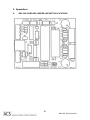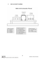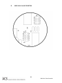
1
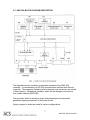
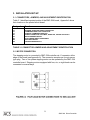
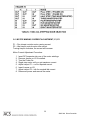
PRODUCT USER’S MANUAL
SMC-32A
Serial Stepping Motor
Driver/Controller
www.ACSMotion.com
Revision
1.5
TABLE OF CONTENTS
1.
General Information
4
1.1
Warranty
4
1.2
Assistance and Maintenance Agreements
4
1.3
Documentation Discrepancies
5
1.4
Service Procedure
5
2.
SMC-32A DESCRIPTION
6
2.1
SMC-32A CONTROLLER FEATURES
6
2.2
SMC-32A BLOCK DIAGRAM DESCRIPTION
7
2.3
SPECIFICATIONS
8
3.
INSTALLATION SET-UP
9
3.1
CONNECTORS, JUMPERS, AND ADJUSTMENT IDENTIFICATION
9
3.2
MOTOR CONNECTION
9
3.3
LIMIT INPUTS, HOME INPUT, JOG INPUTS, CURRENT OFF INPUT,
PROGAM RUN INPUT
12
3.4
COMMUNICATION SPEED
12
3.5
MOTOR ADDRESS SELECTION
13
3.6
FUSING
13
3.7
STEPPING MODE SELECT
13
3.8
MOTOR WINDING CURRENT ADJUSTMENT; P1, P2
14
4.
INSTRUCTION SET
15
4.1
INSTRUCTION SET SUMMARY
15
4.2
SINGLE CHARACTER INSTRUCTION SUMMARY
16
4.3
ERROR RESPONSES
17
4.4
STEPPING RATE INDEXES
17
4.5
JOG RATE INDEX: J
18
4.6
CONSTANT RATE INDEX: C
18
4.7
VELOCITY RATE INDEX: V
19
2
SMC-32A Driver/Controller
4.8
RAMP INDEX: R
19
4.9
MOVE NUMBER OF STEPS AT CONSTANT RATE: M
21
4.10
GO TO ABSOLUTE POSITION: G
21
4.11
INDEX TO RELATIVE POSITION: I
22
4.12
FINISH, DECELERATING STOP: F
22
4.13
QUIT, IMMEDIATE STOP: Q
22
4.14
SEEK HOME POSITION: H
23
4.15
EXAMINE MOTOR STATUS: X
23
4.16
EXAMINE LIMITS AND HOME INPUTS: E
23
4.17
ENABLE, DISABLE, EXAMINE LIMIT INTERRUPTS: L
24
4.18
TURN ON/OFF MOTOR WINDING CURRENT OR EXAMINE IT: W
24
4.19
EXAMINE OR SET ABSOLUTE POSITION: P
24
4.20
SAVE MOTION INDEXES: S
25
4.21
LOAD MOTION PARAMETER DEFAULTS: D
25
4.22
TEST UNIT: T
25
5.
Appendices
26
A.
SMC-32A ON-BOARD JUMPER AND SETTING LOCATIONS
26
C.
SMC-32A PINOUT DIAGRAM
27
D.
SMC-32A H1 & H2 PIN DETAIL
28
E.
SMC-32A RoHS Compliance and EC Conformity Declaration
28
6.
Manual Revision History
3
30
SMC-32A Driver/Controller
1.
General Information
1.1
Warranty
ACS warrants its products to operate within specifications under normal use and
services for a period of one year from the date of shipment. Component
products, spares, replacement parts and repairs are warranted for 90 days.
Software is thoroughly tested and thought to be functional, but is supplied "as is"
with no warranty of any kind covering detailed performance. Accessory products
not manufactured by ACS are covered by the original equipment manufacturers
warranty only.
In exercising this warranty, ACS will repair or, at its option, replace, any product
returned to the customer service department or an authorized service facility
within the warranty period, provided that the warrantor's examination discloses
that the product is defective due to workmanship or materials and has not been
caused by misuse, neglect, accident, or abnormal conditions or operations.
The purchaser is responsible for the transportation and insurance charges arising
from the return of products to the servicing facility. ACS will return all in-warranty
products with transportation prepaid.
This warranty is in lieu of all other warranties, expressed or implied, including but
not limited to any implied warranty of merchantability, fitness, or adequacy for
any particular purpose or use. ACS shall not be liable for any special, incidental,
or consequential damages, whether in contract, or otherwise.
1.2
Assistance and Maintenance Agreements
Answers to questions concerning installation, calibration, and use of ACS
equipment are available from the customer service department, 35 Corporate
Park Drive, Pembroke, MA 02359, (781)829-9228.
ACS offers a selection of customer support services.
For example, maintenance agreements provide extended warranty and allow the
customer to budget maintenance costs after the initial one year warranty has
expired. Other services requested by the customer, such as installation, training,
on-site repair, and addition of engineering improvements, are made available
through specific Supplemental Support Agreements.
4
SMC-32A Driver/Controller
1.3
Documentation Discrepancies
ACS is committed to providing state-of-the-art products and is continually refining
and improving the performance of its products. While physical modifications can
be implemented quite rapidly, the corrected documentation frequently requires
more time to produce. Consequently, this manual may not agree in every detail
with the accompanying product. There may be small discrepancies in the values
of components and, occasionally, minor logic changes. Where any such
inconsistencies exist, please be assured that the unit is correct and incorporates
the most up-to-date circuitry.
1.4
Service Procedure
Products requiring maintenance should be returned to the customer service
department or authorized service facility. If under warranty, ACS will repair and
replace the part at no charge. The purchaser is only responsible for the
transportation charges arising from the return of the goods to the service facility.
For all ACS products in need of repair after the warranty period, the customer
must provide a Purchase Order Number before any inoperative equipment can
be repaired or replaced. The customer will be billed for the parts and labor for the
repair as well as for shipping.
5
SMC-32A Driver/Controller
2. SMC-32A DESCRIPTION
2.1 SMC-32A CONTROLLER FEATURES
This Advanced Control Systems Corp. stepping motor controller contains control
and power drive circuitry to operate any two or four phase stepping motor with
currents up to 3Amp per phase. Several controllers can be controlled by a single
computer communication port.
The stepping motor driver is two phase bi-polar type, which is highly efficient,
and results in cool operation of motors and drivers.
Motor winding current is trimpot adjustable in the range of .125 to 3.00Amps.
Idle winding current is also trimpot adjustable.
Motors can operate in full step mode one-phase on, full step mode-two phases
on, and ministep mode. Ministep modes are 2, 3, 4, 5, 6, or 8 motor ministeps
per full motor step.
The SMC-32A generates constant stepping rates as well as trapezoidal type
velocity profiles. Acceleration, deceleration and top speed are all programmable.
The SMC-32A supports two limit inputs and home position input. The
SMC-32A is designed to operate reliably in adverse industrial environments.
All operational variables are retained in the EEPROM nonvolatile memory.
The SMC-32A understands high level instructions in the form of serial ASCII
messages. The instruction set covers all aspects of computer controlled motion
and is not dependent on the type of host computer or operating systems.
Communication driver/receiver on board is a standard RS-232C type. Internal
communication bus facilitates interconnection for multiple axis operation.
6
SMC-32A Driver/Controller
2.2 SMC-32A BLOCK DIAGRAM DESCRIPTION
The imbedded control processor coordinates operation of the SMC-32A
controller. It communicates via RS-232 communication interface with the host
computer. The programs (firmware) which interprets host instructions are stored
in flash memory. Operational variables, which can be changed, are stored in
non-volatile memory (EEPROM).
The processor which is actually a single chip independent microcontroller
generates stepping sequences to the power drivers.
Option jumpers on board are used for various configurations.
7
SMC-32A Driver/Controller
2.3 SPECIFICATIONS
POWER REQUIREMENTS:
Logic Power Supply
Motor Power Supply
5VDC +5% @50mA typical
12 to 40 VDC @up to 2Amp
Motor supply voltages and currents depend on type of motors being connected.
MOTOR REQUIREMENTS:
Type of Motors
Number of Leads
Max Winding Current
Duty Cycle
Two phase bi-polar stepping motors or four phase
motors connected as two phase
Four, six or eight
3 Amp, adjustable down to .125Amp
100%
MODE OF MOTOR OPERATION:
BiPolar Chopper Drive
Full Step – One Phase On or Two Phases On
Half Step with Torque Compensation
Three, four, five, six or eight ministeps per full step
MOTOR FUSE:
Four Amp, Fast blow
PHYSICAL DIMENSIONS:
Length:
Width:
Max. Height:
4”
3.65”
1.50”
Motor Connectors:
Phoenix type; four terminals
MSTB 2,5/5-ST-5,08 or equivalent.; or terminal block
COMMUNICATION PARAMETERS:
Baud Rates:
2400, 9600, 19200, 57600 baud
Byte Structure:
10 bit ASCII characters:
Start bit, 8 data bits, stop bit; no parity
ENVIRONMENT:
Operating Temperature:
Storage Temperature:
Humidity:
-20°C to 50°C (-4°F to 140°F)
-20°C to 70°C (-4°F to 160°F)
<95% non-condensing
8
SMC-32A Driver/Controller
3. INSTALLATION SET-UP
3.1 CONNECTORS, JUMPERS, AND ADJUSTMENT IDENTIFICATION
Table 3.1 identifies important points of the SMC-32A board, Appendix A show
their location on the printed circuit board.
Designation Function
J1
J2
J3
J4
H1
H2
H3
H4
H5
CONNECTOR FOR MOTOR
TERMINAL STRIP FOR POWER CONNECTION
COMMUNICATIONS PORT CONNECTOR
INTERNAL COMMUNICATIONS BUS
HEADER CONNECTOR FOR LIMITS, HOME JOG, MOTOR OFF INPUTS
MOTOR ADDRESS SELECT
IDLE CURRENT REDUCTION ENABLE
BAUD RATE SELECT
STEPPING MODE SELECT
TABLE 3.1 CONNECTOR JUMPER AND ADJUSTMENT IDENTIFICATION
3.2 MOTOR CONNECTION
The stepping motor is connected to SMC-32A controller via J1 connector at the
edge of the board (see Appendix A). The connector accepts one four pin screw
type plug. Two or four phase stepping motor can be operated by the SMC-32A
controller board. Stepping motors equipped with four, six, or eight leads can be
connected in several ways.
9
SMC-32A Driver/Controller
10
SMC-32A Driver/Controller
11
SMC-32A Driver/Controller
3.3 LIMIT INPUTS, HOME INPUT, JOG INPUTS, CURRENT OFF INPUT,
PROGAM RUN INPUT
The inputs are connected to SMC-32A via a 10 pin header H1. Limit and Home
inputs are normally closed. Jog and Current Off inputs are normally open. Refer
to Appendix A for H1 location on the board.
3.4 COMMUNICATION SPEED
Header H4 (See Appendix A for location) is to be jumped for required
communication baud rate. Selections are no parity and four baud rates.
12
SMC-32A Driver/Controller
3.5 MOTOR ADDRESS SELECTION
The SMC-32A driven motors can be addressed for up to 32 different addresses.
Header H2 selects the binary address of the motor. See table 2.5 for some
examples. See Appendix A for header locations.
3.6 FUSING
The SMC-32A motor control module has an on board fuse. The fuse is to be
rated accordingly to protect the motor; 4 Amp fast blow maximum.
3.7 STEPPING MODE SELECT
There are eight selections for stepping mode. Refer to Table 3.7 for jumper
options.
13
SMC-32A Driver/Controller
3.8 MOTOR WINDING CURRENT ADJUSTMENT; P1, P2
P1 – Run trimpot controls motor running current.
P2 – Idle trimpot controls motor idle current.
Turning trimpot clockwise, the current will increase.
Motor Current Adjustment Procedure:
1.
2.
3.
4.
5.
6.
7.
8.
Insert DC Ampmeter into one of the motor windings.
Remove Jumper on H3 if installed.
Turn the Power On.
Single step motor until you get maximum current.
Adjust trimpot P1 – run for required current.
Insert Jumper on H3.
Adjust trimpot P2 – idle for required idle current.
Disconnect power and remove the meter.
14
SMC-32A Driver/Controller
4. INSTRUCTION SET
4.1 INSTRUCTION SET SUMMARY
Each instruction message is constructed from ASCII characters. Alphabetic
characters can be upper or lower case.
1.
#
Start Character (Hex 23).
2.
aa
Board Address Numeric Characters; 00-31 range.
3.
*
Character “ * “ acts as an all numeric character (Hex
2A).
4.
I
case).
Instruction Alphabetic Characters (upper or lower
5.
+1000
Data Characters.
6.
↵
Termination Character: Carriage Return (Hex 0D).
7.
=
Equal Sign Indicates Data to be Entered (Hex 3D).
8.
En
but correct address.
E followed by a number indicates Error in Instruction,
Example: #12I+1000↵
Motor with address 12 is instructed to index 1000
steps in positive direction immediately.
Response: #12R↵
Instruction Executed!
Example: #12G5000↵
Motor with address 12 is instructed to goto absolute
position 5000.
Response: #12E5↵
Error response, bad instruction structure, direction
sign is missing.
Each instruction with Start Character correct address and termination character
generates a response message from the SMC-32A controller.
15
SMC-32A Driver/Controller
4.2 SINGLE CHARACTER INSTRUCTION SUMMARY
J
Examine or set jog rate index (2-65535 range).
C
Examine or set constant speed index (2-65535 range).
V
Examine or set high speed index (2-255 range).
R
Examine or set acceleration/deceleration index (1-255 range).
M
Move number of steps at constant speed using C index (+8,388,607 steps
range).
G
Go to absolute position using V and R indexes (+8,388,607 steps range).
I
Index number of steps using V and R indexes (+8,388,607 steps range).
F
Decelerate and stop motion (Soft Stop).
H
Seek home position.
Q
Immediate stop of motion (Hard Stop).
X
Examine motor status.
E
Examine limits and home inputs.
L
Examine or enable/disable limit interrupts.
W
Examine or turn on/turn off motor winding current
P
Examine or set absolute position (+8,388,607 range).
S
Save motion indexes.
D
Load motion parameters defaults.
T
Test unit.
16
SMC-32A Driver/Controller
4.3 ERROR RESPONSES
An error response in form #aaEn↵ is generated for various reasons. Instruction
itself is ignored.
1. Instruction structure following #aa is not recognizable or data is out of
range.
2. A motion instruction is executed while motor is already stepping.
3. A motion instruction is executed but motor current is shut off by manual
input W=0 instruction.
4. A motion instruction is executed but limit in that particular direction is
activated.
5. Quit or finish instruction is executed but motor is already stopped.
The following table describes error responses.
E1
E2
E3
E4
E5
E6
E7
Wrong instruction character
Motor is stepping
Wrong data
Motor is stopped
Bad instruction structure
Current turned off
Limits activated or current Off
4.4 STEPPING RATE INDEXES
Stepping rate indexes define stepping rate for jog, move, index, and go motion
control instructions. Actual stepping rate in steps/sec is calculated by formula:
Step Rate = 115200/Rate Index (Steps/Sec)
Jog and move are constant rate instructions (no acceleration) and should be set
below start/stop rate of the motor load combination. Table 4.1 shows some
stepping rate calculations.
17
SMC-32A Driver/Controller
4.5 JOG RATE INDEX: J
Instruction:
Response:
#aaJ=500↵
#aaR↵
Set Jog Rate Index to 500; aa = 00 to 50
Instruction accepted
Instruction:
Response:
per second
#aaJ↵
#aaJ=500↵
Examine Jog Rate Index; aa = 00 only
Jog Rate Index is set to 500 which is 230 steps
Notes: Jog Rate Index range is 2 to 65535. Jog Rate Index controls stepping
rate when operating manual jog toggle switches which are connected to Header
H1, Pins 1 and 3. Jog Rate should be set below start/stop stepping rate of
motor/load combination. Jog Rate Index can be changed any time. It takes
effect on the next jog motion.
4.6 CONSTANT RATE INDEX: C
Instruction:
Response:
#aaC=400↵
#aaR↵
Set Constant Rate Index to 400; aa = 00 to 50
Instruction accepted
Instruction:
#aaC↵
Examine Constant Rate Index; aa = 00 only
18
SMC-32A Driver/Controller
Response: #aaC=400↵
steps per second.
Constant Rate Index is set to 400 which is 288
Notes: Constant Rate Index is 2 to 65535 Constant Rate Index controls stepping
rate when M motion is executed. Constant Rate Index can be changed any time.
It takes effect immediately.
4.7 VELOCITY RATE INDEX: V
Instruction:
Response:
#aaV=20↵
#aaR↵
Instruction: #aaV↵
Response: #aaV=20↵
steps per second.
Set Velocity Rate Index to 20; aa = 00 to 50
Instruction accepted
Examine Velocity Rate Index; aa = 00 only
Velocity Rate Index is set to 20 which is 5760
Notes: Velocity Rate Index controls top stepping rate while executing G or I
motion instruction. Velocity Rate Index range is 2 to 255. Velocity index can be
changed any time. It takes effect on the next high speed motion.
4.8 RAMP INDEX: R
Instruction:
Response:
#aaR=150↵
#aaR↵
Set Ramp Index to 150; aa = 00 to 50
Instruction accepted
Instruction:
Response:
#aaR↵
#aaR=150↵
Examine Ramp Index; aa = 00 only
Ramp Index is set to 150
Note: Ramp Index range is 1 to 255. Ramp index controls
acceleration/deceleration. ramp while executing Go or Index instruction. Index 1
sets the slowest ramp, index 255 is the fastest ramp. It can be changed any time
and it takes effect on the next high speed motion.
Some motors have a resonant point where there is no torque at certain
frequencies. In such cases, the motor has to be started at a lower speed than
the resonant point in order to fly into a higher speed area. To minimize the time
to stay on the resonant point, higher ramp index for acc/dec must be applied. It
is recommended that a damper should be used to increase the inertia moment if
the motor goes in the resonant point with a small load.
19
SMC-32A Driver/Controller
TORQUE
STEPPING RATE
RESONANT POINT
Actual ramping rate in step/sec/sec is calculated by formula:
Ramp Rate = 720,000/(256 – Ramp Index)
Table 4.2 Shows some ramp rate calculations.
20
SMC-32A Driver/Controller
4.9 MOVE NUMBER OF STEPS AT CONSTANT RATE: M
Instruction:
Response:
#aaM+2000↵ Move 2000 steps in positive direction; aa = 00 to 50
#aaR↵
Move instruction accepted
Instruction:
to 50
Response:
#aaM-500↵
Move 500 steps in negative direction; aa = 00
#aaR↵
Move instruction accepted
Instruction: ##aaM+↵
Move in positive direction until Quit instruction
is executed Or + Limit is activated.
Response: #aaR↵
Move instruction accepted.
Instruction:
Response:
#aaM-↵
#aaR↵
Move in negative direction (same as positive).
Move instruction accepted.
The preset constant rate “C” can be changed at any time (changing stepping rate
on the fly). See 4.7 Constant Rate Index.
Note: Motion Execute Instruction. Motor steps at constant rate C; no
acceleration or deceleration. Constant stepping rate is to be set lower than
start/stop rate of the motor load combination. Move commands are used when
coordinated motion is required. Stepping rate is precisely controlled.
4.10 GO TO ABSOLUTE POSITION: G
Instruction:
to 50
Response:
#aaG+12345↵
Go to absolute position +12345; aa = 00
#aaR↵
Instruction accepted
Instruction:
Response:
#aaG+0↵
#aaR↵
Go to zero position; aa = 00 to 50
Instruction accepted
21
SMC-32A Driver/Controller
Notes: G Instruction is used when rapid motion is required. Motor accelerates to
high speed executing trapezoidal or triangular velocity profile. Motion indexes R
and V control the shape of velocity profile.
4.11 INDEX TO RELATIVE POSITION: I
Instruction:
#aaI-6000↵
Step 6000 steps from current position in
negative direction; aa = 00 to 50
Response:
#aaR↵
Instruction accepted.
Instruction:
#aaI+1↵
00 to 50
Execute single step in positive direction; aa =
Response:
#aaR↵
Instruction accepted
Notes: I Instruction is similar to G instruction. Motor accelerates to high speed
defined by R and V indexes. Runs at high speed, then decelerates and stops,
completing the instructed number of steps.
4.12 FINISH, DECELERATING STOP: F
Instruction:
Response:
#aaF↵
#aaR↵
Decelerate and stop motor; aa = 00 to 50
Instruction accepted
Notes: Finish instruction works only when G or I type of motion is being
executed. Motor decelerates to base speed and stops. No steps are lost and
position counter stays accurate.
4.13 QUIT, IMMEDIATE STOP: Q
Instruction:
Response:
#aaQ↵
#aaR↵
Motor stop immediately; aa = 00 to 50
Instruction accepted
22
SMC-32A Driver/Controller
Notes: Quit instruction, works whenever motor is stepping instructed by G, I, M,
H instructions.
4.14 SEEK HOME POSITION: H
Instruction:
Response:
#aaH+↵
#aaR↵
Seek Home in positive direction; aa = 00 to 50
Instruction accepted
Notes: Motor moves at constant rate (C) in positive direction until Home position
is found (Home Switch activated). Motor will stop if it hits active Limit switch or
Quit instruction is received.
Instruction:
Response:
#aaH-↵
#aaR↵
Seek Home in negative direction; aa = 00 to 50
Instruction accepted
Notes: Same as for positive direction.
4.15 EXAMINE MOTOR STATUS: X
Instruction:
50
Response:
Or
Response:
#aaX↵
Examine if motor is stepping; aa = 00 to
#aaX=0↵
Motor stopped.
#aaX=1↵
Motor is stepping
Notes: Numeric character zero or one represents motor status.
4.16 EXAMINE LIMITS AND HOME INPUTS: E
Instruction: #aaE↵
inputs; aa = 00 only.
Response: #aaE=000↵
Or
Response: #aaE=001↵
Examine Status of Limit and home
All three inputs are Low
Limits are Low, home input is HI
Note: Numeric character zero or one represent Low or High level respectively on
time inputs.
First character is L+ (Limit in Positive direction).
Second character is L- (Limit in Negative direction).
Third character is for H (Home input).
23
SMC-32A Driver/Controller
4.17 ENABLE, DISABLE, EXAMINE LIMIT INTERRUPTS: L
Instruction:
#aaL=1↵
Enable Limits interrupts; aa = 00 to 50
Response:
#aaR↵
Instruction executed
Instruction:
Response:
#aaL↵
#aaL=1↵
Examine Limit interrupts; aa = 00 only
Interrupts are enabled
Note: Numeric character one represents enabled limits, zero represents
disabled limits. The same characters are used to enable or disable limits. When
limits are enabled, limit inputs must be connected to limit switches which present
normally Low status. Limits can also be jumped on the controller board.
4.18 TURN ON/OFF MOTOR WINDING CURRENT OR EXAMINE IT: W
Instruction:
Response:
#aaW=0↵
#aaR↵
Turn Motor Current Off; aa = 00 to 50
Instruction executed
Instruction:
Response:
#aaW=1↵
#aaR↵
Turn Motor Current On; aa = 00 to 50
Instruction executed
Instruction:
Response:
#aaW↵
#aaW=1↵
Examine Motor Current; aa = 00 only
Motor Current is On
Note: This is remote (host) control of motor current. Position is not affected by
this instruction. Motor current can be turned On/Off manually with on-board
toggle switch SW-0. Manual control has higher priority than remote control.
4.19 EXAMINE OR SET ABSOLUTE POSITION: P
Instruction:
Response:
#aaP=+0↵
#aaR↵
Instruction:
Response:
#aaP↵
#aaP=+0↵
Set Position counter to zero; aa = 00 to 50
Instruction executed
Examine Position; aa = 00 only
Position is zero
Note: Position can be examined at all times. Direction sign + or – is always
required. Position cannot be changed when motor is stepping.
24
SMC-32A Driver/Controller
4.20 SAVE MOTION INDEXES: S
Instruction:
Response:
#aaS↵
#aaR↵
Save motion indexes; aa = 00 only
Instruction executed
Note: Motion Indexes J, C, V, R are saved to nonvolatile memory (EEPROM)
and are reloaded on the next power-up.
4.21 LOAD MOTION PARAMETER DEFAULTS: D
Instruction:
Response:
#aaD↵
#aaR↵
Load defaults; aa = 00 only
Instruction executed
Note: Default indexes are set as follows:
V – Top rate index to 15 (7680 steps/sec)
C - Constant rate index to 300 (384 steps/sec)
J – Jog rate index to 300 (384 steps/sec)
R – Ramp index to 100
4.22 TEST UNIT: T
Instruction: #aaT↵
Response: #aaSMC32B-R0↵
Test the Unit; aa = 00 only
Note: aa – register address
SMC32B – controller model
R0 – firmware revision number
25
SMC-32A Driver/Controller
5. Appendices
A.
SMC-32A ON-BOARD JUMPER AND SETTING LOCATIONS
26
SMC-32A Driver/Controller
C.
SMC-32A PINOUT DIAGRAM
27
SMC-32A Driver/Controller
D.
SMC-32A H1 & H2 PIN DETAIL
28
SMC-32A Driver/Controller
E.
RoHS COMPLIANCE AND CE CONFORMITY
Advanced Control Systems Corporation motor drivers and controllers are
designed for world wide installation and use and designed to comply with
requirements of certain governmental regulating agencies. Although ACS drivers
and controllers are technically considered motion control components and may
not be within the scope of the European Union’s CE (Conformité Européenne)
directives, ACS looks to provide its customers with solutions that meet world
acceptance.
The following guidelines provide advice as to additional elements required to
install an ACS driver/controller into a CE compliant system. Additional installation
measures may be required at some locations. The ultimate responsibility for the
design, fabrication and installation of a CE compliant machine resides with the
builder.
Low Voltage Directive (LVD) Installation Requirements:
• Mains power supply to be fused.
• Driver/Controller safety earth to be grounded.
• Stepping motor safety earth to be grounded.
• Installation such that the live terminals (terminal block) are not accessible under
normal operation.
Electromagnetic Compatibility (EMC) Installation Requirements:
• Mains power supply to be filtered.
• Varistors or other voltage surge limiting devices to be installed in order to
meet the requirements of EN61000-4-5.
•Transient suppression to be installed.
• 360º EMC shielded motor cabling to be used (limit switches included).
• EMC compliant stepping motors to be used.
• Clip on ferrite absorbers to be installed on all cables.
The SMC-32 Series Driver/Controllers are available in RoHS Compliant models
confirming to the Directive on the Restriction of the Use of Certain Hazardous
Substances in Electrical and Electronic Equipment 2002/95/EC. RoHS compliant
part numbers for the SMC Series are;
SMC-32 A+
SMC-32 B+
29
SMC-32A Driver/Controller
6. Manual Revision History
SMC-32A User’s Manual Revision History
Revision
1.0
1.1
1.2
1.3
1.4
1.5
Date of
Issue
7-11-05
7-11-05
4-13-06
5-3-06
5-1-07
Section
4.7
4.10
5.3
App. D
App. E
Original Release
Changes to section
Changes to section
Added Pinout diagram
Added H1, H2 Pin detail
Added RoHS and CE Marking
30
SMC-32A Driver/Controller