1
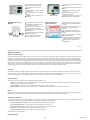
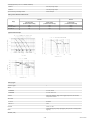
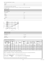
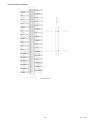
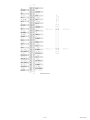
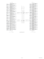
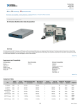
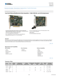
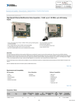
Technical Sales
(866) 531-6285
[email protected]
Requirements and Compatibility | Ordering Information | Detailed Specifications | Pinouts/Front Panel Connections
For user manuals and dimensional drawings, visit the product page resources tab on ni.com.
Last Revised: 2014-11-06 07:14:43.0
High-Accuracy M Series Multifunction DAQ - 18-Bit, up to 625 kS/s, up to 32 Analog Inputs
16 or 32 analog inputs at 18 bits, 625 kS/s (500 kS/s scanning)
Up to 48 TTL/CMOS digital I/O lines (up to 32 hardware-timed at 10 MHz)
Up to 4 analog outputs at 16 bits, 2.8 MS/s (3 μs full-scale settling)
Two 32-bit, 80 MHz counter/timers
7 programmable input ranges (±100 mV to ±10 V) per channel
Analog and digital triggering
Programmable, onboard lowpass filtering
NI-MCal calibration technology for improved measurement accuracy
Overview
NI M Series high-accuracy multifunction data acquisition (DAQ) devices are optimized for 18-bit analog input accuracy. This resolution is equivalent to 5½ digits for DC
measurements. To ensure accuracy, the NI-PGIA 2 amplifier technology is optimized for low noise and fast settling to 18 bits, and the onboard lowpass filter rejects
high-frequency noise and prevents aliasing. M Series devices are ideal for applications including test, control, and design. All high-accuracy devices have a minimum of 16 analog
inputs, 24 digital I/O lines, seven programmable input ranges, analog and digital triggering, and two counter/timers. They also have an extended two-year calibration interval.
Back to Top
Requirements and Compatibility
OS Information
Driver Information
Software Compatibility
Linux®
NI-DAQmx
ANSI C
Mac OS X
NI-DAQmx Base
LabVIEW
Windows 2000/XP
LabWindows/CVI
Windows 7
Measurement Studio Professional Edition
Windows Vista x64/x86
Visual Basic
Visual Studio .NET
Back to Top
Comparison Tables
Family Bus
Analog
Inputs
AI Resolution
(Bits)
Analog
Outputs
AO Resolution
(Bits)
Max AO Update Rate
(MS/s)
AO Range
Digital
I/O
Correlated
(clocked) DIO
NI 6280
PCI,
PXI
16
18
-
-
-
-
24
8, up to 10 MHz
NI 6281
PCI,
PXI
16
18
2
16
2.8
Programmable per
channel
24
8, up to 10 MHz
NI 6284
PCI,
PXI
32
18
-
-
-
-
48
32, up to 10 MHz
NI 6289
PCI,
PXI
32
18
4
16
2.8
Programmable per
channel
48
32, up to 10 MHz
1/19
www.ni.com
Back to Top
Application and Technology
M Series for Test
For test, you can use M Series high-accuracy analog inputs and 10 MHz digital lines with NI signal conditioning for applications including electronics test, component
characterization, and sensor and signal measurements requiring instrument-class accuracy. The 18-bit analog-to-digital converter (ADC) and available filtering provide a 4 times
increase in resolution and 5 times more measurement sensitivity. With fast sampling rates and a low noise floor, these devices can accurately acquire dynamic signals. For better
noise rejection, the onboard lowpass filters significantly improve device accuracy. Advanced analog clamping circuitry protects the hardware from overvoltage conditions and
ensures accurate measurements on nonsaturated channels. High-accuracy M Series devices are compatible with NI SCC and SCXI signal conditioning platforms, which provide
amplification, filtering, and power for virtually every type of sensor. These platforms also are compliant with IEEE 1451.4 smart transducer electronic data sheet (TEDS) sensors,
which offer digital storage for sensor data sheet information.
M Series for Control
M Series digital lines can drive 24 mA for relay and actuator control. By clocking the digital lines as fast as 10 MHz, you can use these lines for pulse-width modulation (PWM) to
control valves, motors, fans, lamps, and pumps. With four waveform analog outputs, two 80 MHz counter/timers, and six DMA channels, M Series devices can execute multiple
control loops simultaneously. The analog outputs on the high-accuracy M Series devices can generate up to 2.86 MS/s and provide user-defined programmable offsets and
ranges for maximum waveform resolution over any custom range. High-accuracy M Series devices also have direct support for encoder measurements, protected digital lines, and
digital debounce filters for control applications. With up to 32 analog inputs, 32 clocked digital lines, and four analog outputs, you can execute multiple control loops with a single
device. For higher-count control loops, you can use M Series devices in conjunction and tightly synchronized with National Instruments analog output devices for 64 or more
loops. With the NI SoftMotion Development Module for LabVIEW, you can create a complete custom motion controller with M Series devices.
M Series for Design
For design applications, you can use the wide range of I/O - from 32 analog inputs to 48 digital lines - to measure and verify prototype designs. M Series devices and NI LabVIEW
SignalExpress interactive measurement software deliver benchtop measurements to the PC. With LabVIEW SignalExpress interactive configuration-based steps, you can quickly
create design verification tests. The fast acquisition and generation rates of high-speed M Series devices along with LabVIEW SignalExpress provide on-the-fly design analysis.
You can convert your tested and verified LabVIEW SignalExpress projects to LabVIEW applications for immediate M Series DAQ use and bridge the gap between test, control,
and design applications.
Hybrid-Slot-Compatible PXI Modules
M Series modules for PXI are hybrid-slot-compatible so that you can use them in both PXI slots and the hybrid slots found in new PXI Express chassis. The PXI Systems Alliance
specifies that hybrid-slot-compatible PXI modules use modified slot connectors to mechanically fit in both PXI slots and hybrid slots. This mechanical change:
Provides compatibility with past, current, and future PXI chassis
Maintains existing product specifications
Requires no software changes (application or driver)
Maintains speed and capability of all PXI communication (PXI Express signaling is not provided)
However, hybrid-slot-compatible PXI modules do not include the pins used to implement PXI local bus communication, which is used for backplane SCXI control from the
right-most PXI slot in PXI/SCXI combination chassis (NI PXI-1010, PXI-1011, PXI-1050, and PXI-1052). For these applications, NI provides unmodified M Series PXI modules that
maintain the required local bus capabilities. Refer to the SCXI Control of PXI/SCXI Combination Chassis section in the Ordering Information section for part numbers.
Simultaneous and Intelligent Data Acquisition
When you need to obtain performance from a data acquisition device beyond the capabilities of a multifunction DAQ device, National Instruments provides simultaneous sampling
with the S Series and intelligent DAQ with the R Series. The S Series architecture dedicates an ADC per channel to provide higher aggregate sampling rates compared to
multiplexed devices. S Series devices are ideal for applications including IF digitization, transient recording, ultrasound and sonar testing, and high-energy physics.
R Series multifunction DAQ devices contain a 1M/3M gate field-programmable gate array (FPGA) that is reconfigurable using the NI LabVIEW FPGA Module. These devices have
up to eight independent 16-bit analog inputs with up to 200 kHz simultaneous sampling, up to eight independent 16-bit analog outputs with up to 1 MHz simultaneous update
rates, and up to 96 digital I/O lines configurable at rates up to 40 MHz. You can customize these devices to develop capabilities such as complete control over the synchronization
and timing of all signals and operations; user-defined onboard decision-making logic; and digital lines individually configurable as input, output, counter/timers, PWM, flexible
encoder inputs, or user-defined communication protocols.
Signal Conditioning
Signal conditioning is required for sensor measurements or voltage inputs greater than 10 V. NI SCXI is a versatile, high-performance signal conditioning platform, optimized for
high-channel-count applications. NI SCC provides portable, flexible signal conditioning options on a per-channel basis. Visit ni.com/sigcon for resources on available NI signal
conditioning.
Back to Top
Ordering Information
For a complete list of accessories, visit the product page on ni.com.
Back to Top
Software Recommendations
LabVIEW Professional
Development System for
Windows
Advanced software tools for large project
development
SignalExpress for Windows
2/19
Quickly configure projects without
programming
www.ni.com
NI LabWindows™/CVI for
Windows
Automatic code generation using DAQ
Assistant and Instrument I/O Assistant
Control over 400 PC-based and stand-alone
instruments
Tight integration with a wide range of
hardware
Log data from more than 250 data acquisition
devices
Advanced measurement analysis and digital
signal processing
Perform basic signal processing, analysis,
and file I/O
Open connectivity with DLLs, ActiveX, and
.NET objects
Scale your application with automatic
LabVIEW code generation
Capability to build DLLs, executables, and
MSI installers
Create custom reports or easily export data
to LabVIEW, DIAdem or Microsoft Excel
NI Measurement Studio
Professional Edition
Real-time advanced 2D graphs and charts
Complete hardware compatibility with IVI,
VISA, DAQ, GPIB, and serial
Customizable graphs and charts for WPF,
Windows Forms, and ASP.NET Web Forms
UI design
Analysis libraries for array operations, signal
generation, windowing, filters, signal
processing
Analysis tools for array manipulation, signal
processing statistics, and curve fitting
Simplified cross-platform communication with
network variables
Measurement Studio .NET tools (included in
LabWindows/CVI Full only)
The mark LabWindows is used under a
license from Microsoft Corporation.
Hardware integration support with native
.NET data acquisition and instrument control
libraries
Automatic code generation for all NI-DAQmx
data acquisition hardware
Intelligent and efficient data-logging libraries
for streaming measurement data to disk
Support for Microsoft Visual Studio .NET
2012/2010/2008
Back to Top
Support and Services
System Assurance Programs
NI system assurance programs are designed to make it even easier for you to own an NI system. These programs include configuration and deployment services for your NI PXI,
CompactRIO, or Compact FieldPoint system. The NI Basic System Assurance Program provides a simple integration test and ensures that your system is delivered completely
assembled in one box. When you configure your system with the NI Standard System Assurance Program, you can select from available NI system driver sets and application
development environments to create customized, reorderable software configurations. Your system arrives fully assembled and tested in one box with your software preinstalled.
When you order your system with the standard program, you also receive system-specific documentation including a bill of materials, an integration test report, a recommended
maintenance plan, and frequently asked question documents. Finally, the standard program reduces the total cost of owning an NI system by providing three years of warranty
coverage and calibration service. Use the online product advisors at ni.com/advisor to find a system assurance program to meet your needs.
Calibration
NI measurement hardware is calibrated to ensure measurement accuracy and verify that the device meets its published specifications. To ensure the ongoing accuracy of your
measurement hardware, NI offers basic or detailed recalibration service that provides ongoing ISO 9001 audit compliance and confidence in your measurements. To learn more
about NI calibration services or to locate a qualified service center near you, contact your local sales office or visit ni.com/calibration.
Technical Support
Get answers to your technical questions using the following National Instruments resources.
Support - Visit ni.com/support to access the NI KnowledgeBase, example programs, and tutorials or to contact our applications engineers who are located in NI sales
offices around the world and speak the local language.
Discussion Forums - Visit forums.ni.com for a diverse set of discussion boards on topics you care about.
Online Community - Visit community.ni.com to find, contribute, or collaborate on customer-contributed technical content with users like you.
Repair
While you may never need your hardware repaired, NI understands that unexpected events may lead to necessary repairs. NI offers repair services performed by highly trained
technicians who quickly return your device with the guarantee that it will perform to factory specifications. For more information, visit ni.com/repair.
Training and Certifications
The NI training and certification program delivers the fastest, most certain route to increased proficiency and productivity using NI software and hardware. Training builds the skills
to more efficiently develop robust, maintainable applications, while certification validates your knowledge and ability.
Classroom training in cities worldwide - the most comprehensive hands-on training taught by engineers.
On-site training at your facility - an excellent option to train multiple employees at the same time.
Online instructor-led training - lower-cost, remote training if classroom or on-site courses are not possible.
Course kits - lowest-cost, self-paced training that you can use as reference guides.
Training memberships and training credits - to buy now and schedule training later.
Visit ni.com/training for more information.
Extended Warranty
3/19
www.ni.com
NI offers options for extending the standard product warranty to meet the life-cycle requirements of your project. In addition, because NI understands that your requirements may
change, the extended warranty is flexible in length and easily renewed. For more information, visit ni.com/warranty.
OEM
NI offers design-in consulting and product integration assistance if you need NI products for OEM applications. For information about special pricing and services for OEM
customers, visit ni.com/oem.
Alliance
Our Professional Services Team is comprised of NI applications engineers, NI Consulting Services, and a worldwide National Instruments Alliance Partner program of more than
700 independent consultants and integrators. Services range from start-up assistance to turnkey system integration. Visit ni.com/alliance.
Back to Top
Detailed Specifications
Specifications listed below are typical at 25 °C unless otherwise noted. Refer to the M Series User Manual for more information about NI 628 x devices.
Analog Input
Number of channels
NI 6280/6281
8 differential or 16 single ended
NI 6284/6289
16 differential or 32 single ended
ADC resolution
18 bits
DNL
No missing codes guaranteed
INL
Refer to the AI Absolute Accuracy Tables
Sampling rate
Maximum
625 kS/s single channel,
500 kS/s multi-channel (aggregate)
Minimum
No minimum
Timing accuracy
50 ppm of sample rate
Timing resolution
50 ns
Input coupling
DC
Input range
±10 V, ±5 V, ± 2 V, ±1 V, ±0.5 V, ± 0.2 V, ± 0.1 V
Maximum working voltage for analog inputs
(signal + common mode)
±11 V of AI GND
CMRR (DC to 60 Hz)
110 dB
Input impedance
Device on
AI+ to AI GND
>10 GΩ in parallel with 100 pF
AI- to AI GND
>10 GΩ in parallel with 100 pF
Device off
AI+ to AI GND
820 Ω
AI- to AI GND
820 Ω
Input bias current
±100 pA
Crosstalk (at 100 kHz)
Adjacent channels
-75 dB
Non-adjacent channels
-95 dB
Small signal bandwidth (-3 dB)
750 kHz filter off,
40 kHz filter on
Input FIFO size
2,047 samples
Scan list memory
4,095 entries
Data transfers
PCI/PXI devices
DMA (scatter-gather), interrupts, programmed I/O
USB devices
USB Signal Stream, programmed I/O
4/19
www.ni.com
Overvoltage protection (AI <0..31>, AI SENSE, AI SENSE 2)
Device on
±25 V for up to eight AI pins
Device off
±15 V for up to eight AI pins
Input current during overvoltage condition
±20 mA max/AI pin
Settling Time for Multichannel Measurements
Filter Off
Range
±10 V, ±5 V
±2 V, ±1 V, ±0.5 V
±0.2 V, ±0.1 V
Filter On
±15 ppm of Step
(±4 LSB for Full Scale Step)
±4 ppm of Step
(±1 LSB for Full Scale Step)
±4 ppm of Step
(±1 LSB for Full Scale Step)
2 μs
8 μs
50 μs
2.5 μs
8 μs
50 μs
3 μs
8 μs
50 μs
Typical Performance Graphs
Analog Triggers
Number of triggers
1
Source
NI 6280/6281
AI <0..15>, APFI 0
NI 6284/6289
AI <0..31>, APFI <0..1>
Start Trigger, Reference Trigger, Pause Trigger, Sample Clock, Convert Clock,
Sample Clock Timebase
Functions
Source level
AI <0..31>
±Full scale
APFI <0..1>
±10 V
Resolution
10 bits, 1 in 1024
Modes
Analog edge triggering, analog edge triggering with hysteresis, and analog window
triggering
Bandwidth (-3 dB)
5/19
www.ni.com
AI <0..31>
700 kHz filter off,
40 kHz filter on
APFI <0..1>
5 MHz
Accuracy
±1%
APFI <0..1> characteristics
Input impedance
10 kΩ
Coupling
DC
Protection
Power on
±30 V
Power off
±15 V
Analog Output
Number of channels
NI 6280/6284
0
NI 6281
2
NI 6289
4
DAC resolution
16 bits
DNL
±1 LSB
Monotonicity
16 bit guaranteed
Accuracy
Refer to the AO Absolute Accuracy Table
Maximum update rate
1 channel
2.86 MS/s
2 channels
2.00 MS/s
3 channels
1.54 MS/s
4 channels
1.25 MS/s
Timing accuracy
50 ppm of sample rate
Timing resolution
50 ns
Output range
Offset ± reference, includes ±10 V, ±5 V, ±2 V, and ±1 V calibrated ranges
Offset
0 V, 5 V, APFI <0..1>, AO <0..3> 1
Reference
10 V, 5 V, 2 V, 1 V, APFI <0..1>, AO <0..3> 1
Maximum output level
±11 V
Output coupling
DC
Output impedance
0.2 Ω
Output current drive
±5 mA
Overdrive protection
±25 V
Overdrive current
20 mA
Power-on state
±5 mV2
Power-on glitch
2.3 V peak for 1.2 s
Output FIFO size
8,191 samples shared among channels used
Data transfers
PCI/PXI devices
DMA (scatter-gather), interrupts, programmed I/O
USB devices
USB Signal Stream, programmed I/O
AO waveform modes:
Non-periodic waveform
Periodic waveform regeneration mode from onboard FIFO
Periodic waveform regeneration from host buffer including dynamic update
Settling time, full scale step 15 ppm (1 LSB)
3 μs
Slew rate
20 V/μs
6/19
www.ni.com
Glitch energy at midscale transition, ±10 V range
1
Magnitude
15 mV
Duration
0.5 μs
An AO channel cannot be a reference or offset to itself.
2
For all USB-6281/6289 Screw Terminal devices, when powered on, the analog output signal is not defined until after USB
configuration is complete.
External Reference
APFI <0..1> characteristics
Input impedance
10 kΩ
Coupling
DC
Protection
Power on
±30 V
Power off
±15 V
Range
±11 V
Calibration (AI and AO)
Recommended warm-up time
PCI/PXI devices
15 minutes
USB devices
30 minutes
Calibration interval
2 years
AI Absolute Accuracy Table (Filter On)
Nominal Range
Residual
Gain
Error
(ppm of
Reading)
Gain
Tempco
(ppm/°C)
Reference
Tempco
Residual
Offset
Error
(ppm of
Range)
Offset
Tempco
(ppm of
Range/°C)
INL Error
(ppm of
Range)
Random
Noise,
σ (µVrms)
Absolute
Accuracy
at
Full
Sensitivity
Positive
Full
Scale
Negative
Full
Scale
10
-10
40
17
1
8
11
10
60
980
5
-5
45
17
1
8
11
10
30
510
12
2
-2
45
17
1
8
13
10
12
210
4.8
2
(µV)
Scale1 (µV)
24
1
-1
55
17
1
15
15
10
7
120
2.8
0.5
-0.5
55
17
1
30
20
10
4
70
1.6
0.2
-0.2
75
17
1
45
35
10
3
39
1.2
0.1
-0.1
120
17
1
60
60
10
2
28
0.8
Accuracies listed are valid for up to two years from the device external calibration.
AbsoluteAccuracy = Reading · (GainError) + Range · (OffsetError) + NoiseUncertainty
GainError = ResidualAIGainError + GainTempco · (TempChangeFromLastInternalCal) + ReferenceTempco · (TempChangeFromLastExternalCal)
OffsetError = ResidualAIOffsetError + OffsetTempco · (TempChangeFromLastInternalCal) + INL_Error
1
Absolute accuracy at full scale on the analog input channels is determined using the following assumptions:
7/19
www.ni.com
TempChangeFromLastExternalCal = 10 °C
TempChangeFromLastInternalCal = 1 °C
number_of_readings = 100
CoverageFactor = 3 σ
For example, on the 10 V range, the absolute accuracy at full scale is as follows:
GainError = 40 ppm + 17 ppm · 1 + 1 ppm · 10
GainError = 67 ppm
OffsetError = 8 ppm + 11 ppm · 1 + 10 ppm
OffsetError = 29 ppm
AbsoluteAccuracy = 10 V · (GainError) + 10 V · (OffsetError) + NoiseUncertainty
2
AbsoluteAccuracy = 980 μV
Sensitivity is the smallest voltage change that can be detected. It is a function of noise.
AI Absolute Accuracy Table (Filter Off)
Nominal Range
Residual
Gain
Error
(ppm of
Reading)
Gain
Tempco
(ppm/°C)
Reference
Tempco
Residual
Offset
Error
(ppm of
Range)
Offset
Tempco
(ppm of
Range/°C)
INL Error
(ppm of
Range)
Random
Noise,
σ (µVrms)
Absolute
Accuracy
at
Full
Sensitivity
Positive
Full
Scale
Negative
Full
Scale
10
-10
45
17
1
10
11
10
70
1050
28.0
5
-5
50
17
1
10
11
10
35
550
14.0
2
-2
50
17
1
10
13
10
15
230
6.0
1
-1
60
17
1
17
15
10
12
130
4.8
0.5
-0.5
60
17
1
32
20
10
10
80
4.0
0.2
-0.2
80
17
1
47
35
10
9
43
3.6
0.1
-0.1
120
17
1
62
60
10
9
31
3.6
2
(µV)
Scale1 (µV)
Accuracies listed are valid for up to two years from the device external calibration.
AbsoluteAccuracy = Reading · (GainError) + Range · (OffsetError) + NoiseUncertainty
GainError = ResidualAIGainError + GainTempco · (TempChangeFromLastInternalCal) + ReferenceTempco · (TempChangeFromLastExternalCal)
OffsetError = ResidualAIOffsetError + OffsetTempco · (TempChangeFromLastInternalCal) + INL_Error
1
Absolute accuracy at full scale on the analog input channels is determined using the following assumptions:
TempChangeFromLastExternalCal = 10 °C
TempChangeFromLastInternalCal = 1 °C
number_of_readings = 100
CoverageFactor = 3 σ
For example, on the 10 V range, the absolute accuracy at full scale is as follows:
GainError = 45 ppm + 17 ppm · 1 + 1 ppm · 10
GainError = 72 ppm
OffsetError = 10 ppm + 11 ppm · 1 + 10 ppm
OffsetError = 31 ppm
AbsoluteAccuracy = 10 V · (GainError) + 10 V · (OffsetError) + NoiseUncertainty
2
AbsoluteAccuracy = 1050 μV
Sensitivity is the smallest voltage change that can be detected. It is a function of noise.
AO Absolute Accuracy Table
Nominal Range
Positive
Full
Scale
Negative
Full
Scale
10
-10
55
15
1
30
12
32
1540
5
-5
60
15
1
30
17
32
820
2
-2
65
25
1
40
30
32
404
1
-1
85
25
1
57
50
32
259
Gain
Tempco
(ppm/°C)
Reference
Tempco
Residual
Offset Error
(ppm of
Range)
Offset
Tempco
(ppm of
Range/°C)
INL
Error
(ppm of
Range)
Absolute
Accuracy at
Full
Residual
Gain Error
(ppm of
Reading)
8/19
Scale1
(µV)
www.ni.com
1
Absolute Accuracy at full scale numbers is valid immediately following internal calibration and assumes the device is operating within 10 °C of the last external
calibration.
Accuracies listed are valid for up to two years from the device external calibration.
AbsoluteAccuracy = OutputValue · (GainError) + Range · (OffsetError)
GainError = ResidualGainError + GainTempco · (TempChangeFromLastInternalCal) + ReferenceTempco · (TempChangeFromLastExternalCal)
OffsetError = ResidualOffsetError + AOOffsetTempco · (TempChangeFromLastInternalCal) + INL_Error
Digital I/O/PFI
Static Characteristics
Number of channels
NI 6280/6281
24 total
8 (P0.<0..7>) 16 (PFI <0..7>/P1, PFI <8..15>/P2)
NI 6284/6289
48 total
32 (P0.<0..31>) 16 (PFI <0..7>/P1, PFI <8..15>/P2)
I/O type
5 V TTL/CMOS compatible
Ground reference
D GND
Direction control
Each terminal individually programmable as input or output
Pull-down resistor
Input voltage protection
3
50 kΩ typical, 20 kΩ minimum
3
±20 V on up to two pins
Stresses beyond those listed under Input voltage protection may cause permanent damage to the device.
Waveform Characteristics (Port 0 Only)
Terminals used
NI 6280/6281
Port 0 (P0.<0..7>)
NI 6284/6289
Port 0 (P0.<0..31>)
Port/sample size
NI 6280/6281
Up to 8 bits
NI 6284/6289
Up to 32 bits
Waveform generation (DO) FIFO
2,047 samples
Waveform acquisition (DI) FIFO
2,047 samples
DI Sample Clock frequency
PCI/PXI devices
0 to 10 MHz4
USB devices
0 to 1 MHz system dependent4
DO Sample Clock frequency
PCI/PXI devices
Regenerate from FIFO
0 to 10 MHz
Streaming from memory
0 to 10 MHz system dependent 4
USB devices
Regenerate from FIFO
0 to 10 MHz
Streaming from memory
0 to 1 MHz system dependent4
Data transfers
PCI/PXI devices
DMA (scatter-gather), interrupts, programmed I/O
USB devices
USB Signal Stream, programmed I/O
Any PFI, RTSI, AI Sample or Convert Clock, AO Sample Clock, Ctr n Internal Output,
and many other signals
DO or DI Sample Clock source5
4
Performance can be dependent on bus latency and volume of bus activity.
5
The digital subsystem does not have its own dedicated internal timing engine. Therefore, a sample clock must be provided from another subsystem on the device or an external
source.
PFI/Port 1/Port 2 Functionality
9/19
www.ni.com
Functionality
Static digital input, static digital output, timing input, timing output
Timing output sources
Many AI, AO, counter, DI, DO timing signals
Debounce filter settings
125 ns, 6.425 µs, 2.56 ms, disable; high and low transitions; selectable per input
Recommended Operation Conditions
Min
Max
Input high voltage (VIH)
Level
2.2 V
5.25 V
Input low voltage (VIL)
0V
0.8 V
—
—
-24 mA
-16 mA
—
—
24 mA
16 mA
Output high current (IOH)
P0.<0..31>
PFI <0..15>/P1/P2
Output low current (IOL)
P0.<0..31>
PFI <0..15>/P1/P2
Electrical Characteristics
Min
Max
Positive-going threshold (VT+)
Negative-going threshold (VT-)
Level
—
0.8 V
2.2 V
—
Delta VT hysteresis (VT+ - VT-)
0.2 V
—
IIL input low current (Vin = 0 V)
—
-10 µA
IIH input high current (Vin = 5 V)
—
250 µA
Digital I/O Characteristics
General-Purpose Counter/Timers
10/19
www.ni.com
Number of counter/timers
2
Resolution
32 bits
Counter measurements
Edge counting, pulse, semi-period, period, two-edge separation
Position measurements
X1, X2, X4 quadrature encoding with Channel Z reloading; two-pulse encoding
Output applications
Pulse, pulse train with dynamic updates, frequency division, equivalent time
sampling
Internal base clocks
80 MHz, 20 MHz, 0.1 MHz
External base clock frequency
0 MHz to 20 MHz
Base clock accuracy
50 ppm
Inputs
Gate, Source, HW_Arm, Aux, A, B, Z, Up_Down
Routing options for inputs
Any PFI, RTSI, PXI_TRIG, PXI_STAR, analog trigger, many internal signals
FIFO
2 samples
Data transfers
PCI/PCIe/PXI/PXIe devices
Dedicated scatter-gather DMA controller for each counter/timer; interrupts,
programmed I/O
USB devices
USB Signal Stream, programmed I/O
Frequency Generator
Number of channels
1
Base clocks
10 MHz, 100 kHz
Divisors
1 to 16
Base clock accuracy
50 ppm
Output can be available on any PFI or RTSI terminal.
Phase-Locked Loop (PLL) (PCI/PXI Devices Only)
Number of PLLs
1
Reference signal
PXI_STAR, PXI_CLK10, RTSI <0..7>
Output of PLL
80 MHz Timebase; other signals derived from 80 MHz Timebase including 20 MHz
and 100 kHz Timebases
External Digital Triggers
Source
Any PFI, RTSI, PXI_TRIG, PXI_STAR
Polarity
Software-selectable for most signals
Analog input function
Start Trigger, Reference Trigger, Pause Trigger, Sample Clock, Convert Clock,
Sample Clock Timebase
Analog output function
Start Trigger, Pause Trigger, Sample Clock, Sample Clock Timebase
Counter/timer functions
Gate, Source, HW_Arm, Aux, A, B, Z, Up_Down
Digital waveform generation (DO) function
Sample Clock
Digital waveform acquisition (DI) function
Sample Clock
Device-To-Device Trigger Bus
PCI devices
RTSI <0..7>6
PXI devices
PXI_TRIG <0..7>, PXI_STAR
USB devices
None
Output selections
10 MHz Clock; frequency generator output; many internal signals
Debounce filter settings
125 ns, 6.425 µs, 2.56 ms, disable; high and low transitions; selectable per input
6
In other sections of this document, RTSI refers to RTSI <0..7> for PCI devices or PXI_TRIG <0..7> for PXI devices.
Bus Interface
PCI/PXI devices
3.3 V or 5 V signal environment
11/19
www.ni.com
USB devices
USB 2.0 Hi-Speed or full-speed7,8
DMA channels (PCI/PXI devices)
6, analog input, analog output, digital input, digital output, counter/timer 0,
counter/timer 1
USB Signal Stream (USB devices)
4, can be used for analog input, analog output, digital input, digital output,
counter/timer 0, counter/timer 1
All PXI-628x devices support one of the following features:
May be installed in PXI Express hybrid slots
Or, may be used to control SCXI in PXI/SCXI combo chassis
Table 1. PXI/SCXI Combo and PXI Express Chassis Compatibility
M Series Part Number
SCXI Control in PXI/SCXI Combo
Chassis
PXI Express Hybrid Slot Compatible
PXI-6280
191501C-04
No
Yes
PXI-6281
191501C-03
No
Yes
PXI-6284
191501C-02
No
Yes
191501C-01
No
Yes
191501C-11
Yes
No
191501A-0x
191501B-0x
Yes
No
M Series Device
PXI-6289
Earlier versions of PXI-628x
7
If you are using a USB M Series device in full-speed mode, device performance will be lower and you will not be able to achieve maximum sampling/update rates.
8
Operating on a full-speed bus may result in lower performance.
Power Requirements
PCI/PXI devices
Current draw from bus during no-load condition9
+5 V
0.03 A
+3.3 V
0.78 A
+12 V
0.40 A
-12 V
0.06 A
PCI/PXI devices
Current draw from bus during AI and AO overvoltage condition 9
+5 V
0.03 A
+3.3 V
1.26 A
+12 V
0.43 A
-12 V
0.06 A
Caution USB-628x devices must be powered with NI offered AC adapter or a National Electric Code (NEC) Class evice and has appropriate safety certification marks for
country of use.
USB devices
9
Power supply requirements
11 to 30 VDC, 20 W, locking or non-locking power jack with 0.080 in. diameter
center pin, 5/16-32 thread for locking collars
Power supply fuse
2 A, 250 V
Does not include P0/PFI/P1/P2 and +5 V terminals.
Power Limits
Caution Exceeding the power limits may cause unpredictable behavior by the device and/or PC/chassis.
PCI devices
+5 V terminal (connector 0)
1 A max10
+5 V terminal (connector 1)
1 A max10
PXI devices
1 A max10
+5 V terminal (connector 0)
12/19
www.ni.com
+5 V terminal (connector 1)
1 A max10
P0/PFI/P1/P2 and +5 V terminals combined
2 A max
USB devices
+5 V terminal
1 A max11
P0/PFI/P1/P2 and +5 V terminals combined
2 A max
10
Older revisions have a self-resetting fuse that opens when current exceeds this specification. Newer revisions have a traditional fuse that opens when current exceeds this
specification. This fuse is not customer-replaceable; if the fuse permanently opens, return the device to NI for repair.
11
Has a self-resetting fuse that opens when current exceeds this specification.
Physical Requirements
Printed circuit board dimensions
NI PCI-6280/6281/6284/6289
10.6 cm x 15.5 cm (4.2 in. x 6.1 in.)
NI PXI-6280/6281/6284/6289
Standard 3U PXI
Enclosure dimensions (includes connectors)
NI USB-6281/6289 Mass Termination
18.8 x 17.09 x 4.45 cm (7.4 x 6.73 x 1.75 in.)
NI USB-6281/6289 Screw Terminal
26.67 x 17.09 x 4.45 cm (10.5 x 6.73 x 1.75 in.)
NI USB-6258/6289 OEM
Refer to the NI USB-622x/625x/628x OEM User Guide
Weight
NI PCI-6280
151 g (5.3 oz)
NI PCI-6281
158 g (5.6 oz)
NI PCI-6284
159 g (5.6 oz)
NI PCI-6289
167 g (5.9 oz)
NI PXI-6280
218 g (7.7 oz)
NI PXI-6281
225 g (7.9 oz)
NI PXI-6284
229 g (8.1 oz)
NI PXI-6289
237 g (8.4 oz)
NI USB-6281 Mass Termination
1.04 kg (2 lb 4.5 oz)
NI USB-6289 Mass Termination
1.06 kg (2 lb 5.5 oz)
NI USB-6281 OEM
261 g (9.2 oz)
NI USB-6289 OEM
274 g (9.6 oz)
NI USB-6281 Screw Terminal
1.46 kg (3 lb 3.4 oz)
NI USB-6289 Screw Terminal
1.52 kg (3 lb 5.5 oz)
I/O connector
NI PCI/PXI-6280/6281
1 68-pin VHDCI
NI PCI/PXI-6284/6289
2 68-pin VHDCI
NI USB-6281 Mass Termination
1 68-pin SCSI
NI USB-6289 Mass Termination
2 68-pin SCSI
NI USB-6281 OEM
1 34-pin IDC, 1 50-pin IDC
NI USB-6289 OEM
2 34-pin IDC, 2 50-pin IDC
NI USB-6281 Screw Terminal
64 screw terminals
NI USB-6289 Screw Terminal
128 screw terminals
USB-6281/6289 Screw Terminal wiring
16-28 AWG
Maximum Working Voltage12
NI 6280/6281/6284/6289 channel-to-earth
11 V, Measurement Category I
Caution Do not use for measurements within Categories II, III, or IV.
12
Maximum working voltage refers to the signal voltage plus the common-mode voltage.
13/19
www.ni.com
Environmental
Operating temperature
PCI/PXI devices
0 to 55 °C
USB devices
0 to 45 °C
Storage temperature
-20 to 70 °C
Humidity
10 to 90% RH, noncondensing
Maximum altitude
2,000 m
Pollution Degree (indoor use only)
2
Shock and Vibration (PXI Devices Only)
30 g peak, half-sine, 11 ms pulse
(Tested in accordance with IEC-60068-2-27. Test profile developed in accordance
with MIL-PRF-28800F.)
Operational shock
Random vibration
5 to 500 Hz, 0.3 grms
Operating
5 to 500 Hz, 2.4 grms
Nonoperating
(Tested in accordance with IEC-60068-2-64. Nonoperating test profile exceeds the
requirements of MIL-PRF-28800F, Class 3.)
Safety
This product is designed to meet the requirements of the following standards of safety for electrical equipment for measurement, control, and laboratory use:
IEC 61010-1, EN 61010-1
UL 61010-1, CSA 61010-1
Note For UL and other safety certifications, refer to the product label or the Online Product Certification section
Electromagnetic Compatibility
This product meets the requirements of the following EMC standards for electrical equipment for measurement, control, and laboratory use:
EN 61326 (IEC 61326): Class A emissions; Basic immunity
EN 55011 (CISPR 11): Group 1, Class A emissions
AS/NZS CISPR 11: Group 1, Class A emissions
FCC 47 CFR Part 15B: Class A emissions
ICES-001: Class A emissions
Note For the standards applied to assess the EMC of this product, refer to the Online Product Certification section.
Note For EMC compliance, operate this product according to the documentation.
Note For EMC compliance, operate this device with shielded cables.
CE Compliance
This product meets the essential requirements of applicable European Directives as follows:
2006/95/EC; Low-Voltage Directive (safety)
2004/108/EC; Electromagnetic Compatibility Directive (EMC)
Online Product Certification
Refer to the product Declaration of Conformity (DoC) for additional regulatory compliance information. To obtain product certifications and the DoC for this product, visit
ni.com/certification, search by model number or product line, and click the appropriate link in the Certification column.
Environmental Management
NI is committed to designing and manufacturing products in an environmentally responsible manner. NI recognizes that eliminating certain hazardous substances from our
products is beneficial not only to the environment but also to NI customers.
For additional environmental information, refer to the NI and the Environment Web page at ni.com/environment. This page contains the environmental regulations and directives
with which NI complies, as well as other environmental information not included in this document.
Waste Electrical and Electronic Equipment (WEEE)
EU Customers At the end of their life cycle, all products must be sent to a WEEE recycling center. For more information about WEEE recycling centers and National
Instruments WEEE initiatives, visit ni.com/environment/weee.htm.
14/19
www.ni.com
Back to Top
15/19
www.ni.com
Pinouts/Front Panel Connections
NI PCI/PXI-6280 Pinout
16/19
www.ni.com
NI PCI/PXI-6281 Pinout
17/19
www.ni.com
NI PCI/PXI-6284 Pinout
18/19
www.ni.com
NI PCI/PXI-6289 Pinout
Back to Top
©2008 National Instruments. All rights reserved. CVI, DIAdem, LabVIEW, Measurement Studio, National Instruments, National Instruments Alliance Partner, NI, ni.com, NI SoftMotion, SCXI, and SignalExpress are
trademarks of National Instruments. The mark LabWindows is used under a license from Microsoft Corporation. Windows is a registered trademark of Microsoft Corporation in the United States and other countries.
Linux® is the registered trademark of Linus Torvalds in the U.S. and other countries. Other product and company names listed are trademarks or trade names of their respective companies. A National Instruments
Alliance Partner is a business entity independent from National Instruments and has no agency, partnership, or joint-venture relationship with National Instruments.
My Profile | RSS | Privacy | Legal | Contact NI © 2014 National Instruments Corporation. All rights reserved.
19/19
www.ni.com