
1
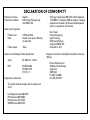
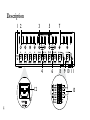
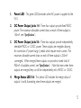
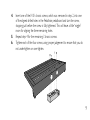
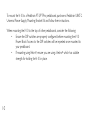
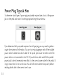
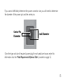
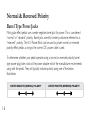
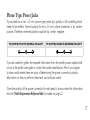
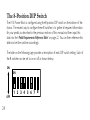
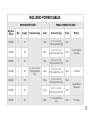
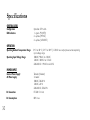
HARDWIRE V-10 POWER BLOCK PREMIUM ISOLATED POWER SUPPLY OWNER’S MANUAL SAFETY INSTRUCTIONS Notice For Customers If Your Unit Is Equipped With A Power Cord. WARNING: THIS APPLIANCE SHALL BE CONNECTED TO A MAINS SOCKET OUTLET WITH A PROTECTIVE EARTHING CONNECTION. The cores in the mains lead are coloured in accordance with the following code: CONDUCTOR L N E LIVE NEUTRAL EARTH GND WIRE COLOR Normal Alt BROWN BLACK BLUE WHITE GREEN/YEL GREEN WARNING: If the ground is defeated, certain fault conditions in the unit or in the system to which it is connected can result in full line voltage between chassis and As colours of the cores in the mains lead of this appliance may not correspond with earth ground. Severe injury or death can then result if the chassis and earth ground are touched simultaneously. the coloured markings identifying the terminals in your plug, proceed as follows: • The core which is coloured green and yellow must be connected to the terminal in the plug marked with the letter E, or with the earth symbol, or coloured The following is indicative of low altitude use; do not use this GREEN and YELLOW - Earth BLUE - Neutral BROWN - Live green, or green and yellow. • The core which is coloured blue must be connected to the terminal marked N or coloured black. • The core which is coloured brown must be connected to the terminal marked L or coloured red. This equipment may require the use of a different line cord, attachment plug, or both, depending on the available power source at installation. If the attachment plug needs to be changed, refer servicing to qualified service personnel who should refer to the following table. The green/yellow wire shall be connected directly to the units chassis. product above 2000m. CAUTION: Ensure vents on the V-10 are not blocked. CAUTION: For Use with Audio/Video Equipment. WARNING: • Apparatet må tilkoples jordet stikkontakt • Apparaten skall anslutas till jordat uttag • Laite on liitettävä suojakoskettimilla varustettuun pistorasiaan WARNING FOR YOUR PROTECTION READ THE FOLLOWING: KEEP THESE INSTRUCTIONS HEED ALL WARNINGS Use only with the cart stand, tripod bracket, or table specified by the manufacture, or sold with the apparatus. When a cart is used, use caution when moving the cart/apparatus combination to avoid injury from tip-over. FOLLOW ALL INSTRUCTIONS The apparatus shall not be exposed to dripping or splashing liquid and no object filled with liquid, such as vases, shall be placed on the apparatus CLEAN ONLY WITH A DRY CLOTH. FOR INDOOR USE ONLY. Refer all servicing to to qualified service personnel. Servicing is required when the apparatus has been damaged in any way, such as power-supply cord or plug is damaged, liquid has been spilled or objects have fallen into the apparatus, the apparatus has been exposed to rain or moisture, does not operate normally, or has been dropped. DO NOT BLOCK ANY OF THE VENTILATION OPENINGS. INSTALL IN ACCORDANCE WITH THE MANUFACTURER’S INSTRUCTIONS. POWER ON/OFF SWITCH: For products provided with a power switch, the power switch DOES NOT break the connection from the mains. DO NOT INSTALL NEAR ANY HEAT SOURCES SUCH AS RADIATORS, HEAT REGISTERS, STOVES, OR OTHER APPARATUS (INCLUDING AMPLIFIERS) THAT PRODUCE HEAT. MAINS DISCONNECT: The plug shall remain readily operable. For rack-mount or installation where plug is not accessible, an all-pole mains switch with a contact separation of at least 3 ONLY USE ATTACHMENTS/ACCESSORIES SPECIFIED BY THE MANUFACTURER. mm in each pole shall be incorporated into the electrical installation of the rack or building. UNPLUG THIS APPARATUS DURING LIGHTNING STORMS OR WHEN UNUSED FOR LONG FOR UNITS EQUIPPED WITH EXTERNALLY ACCESSIBLE FUSE RECEPTACLE: Replace fuse PERIODS OF TIME. with same type and rating only. Do not defeat the safety purpose of the polarized or grounding-type plug. A polarized plug has two blades with one wider than the other. A grounding type plug has two blades and a third grounding prong. The wide blade or third prong are provided for your safety. If the provided plug does not fit your outlet, consult an electrician for replacement of the obsolete outlet. MULTIPLE-INPUT VOLTAGE: This equipment may require the use of a different line cord, attachment plug, or both, depending on the available power source at installation. Connect this equipment only to the power source indicated on the equipment rear panel. To reduce the risk of fire or electric shock, refer servicing to qualified service personnel or equivalent. Protect the power cord from being walked on or pinched particularly at plugs, convenience If connected to 240V supply, a suitable CSA/UL certified power cord shall be used for this supply. receptacles, and the point where they exit from the apparatus. U.K. MAINS PLUG WARNING A molded mains plug that has been cut off from the cord is unsafe. Discard the mains plug at a suitable disposal facility. NEVER UNDER ANY The symbols shown above are internationally accepted symbols that warn of potential hazards with electrical products. The lightning flash with arrowpoint in an equilateral triangle means that there are dangerous voltages present within the unit. The exclamation point in an equilateral triangle indicates that it is necessary for the user to refer to the owner’s manual. These symbols warn that there are no user serviceable parts inside the unit. Do not open the unit. Do not attempt to service the unit yourself. Refer all servicing to qualified personnel. Opening the chassis for any reason will void the manufacturer’s warranty. Do not get the unit wet. If liquid is spilled on the unit, shut it off immediately and take it to a dealer for service. Disconnect the unit during storms to prevent damage. CIRCUMSTANCES SHOULD YOU INSERT A DAMAGED OR CUT MAINS PLUG ELECTROMAGNETIC COMPATIBILITY This device complies with part 15 of the FCC Rules and the Product Specifications noted on the Declaration of Conformity. Operation is subject to the following two conditions: • this device may not cause harmful interference, and INTO A 13 AMP POWER SOCKET. Do not • this device must accept any interference received, use the mains plug without the fuse cover in place. including interference that may cause undesired operation. Replacement fuse covers can be obtained from your local retailer. Replacement fuses are 13 amps and MUST be ASTA approved to BS1362. Operation of this unit within significant electromagnetic fields should be avoided. • use only shielded interconnecting cables. If you want to dispose this product, do not mix it with general household waste. There is a separate collection system for used electronic products in accordance with legislation that requires proper treatment, recovery and recycling. Private households in the 25 member states of the EU, in Switzerland and Norway may return their used electronic products free of charge to designated collection facilities or to a retailer (if you purchase a similar new one). For Countries not mentioned above, please contact your local authorities for a correct method of disposal. By doing so you will ensure that your disposed product undergoes the necessary treatment, recovery and recycling and thus prevent potential negative effects on the environment and human health. DECLARATION OF CONFORMITY Manufacturer’s Name: Manufacturer’s Address: DigiTech 8760 S. Sandy Parkway Sandy, Utah 84070, USA With regard to Directive 2005/32/EC and EC Regulation 1275/2008 of 17 December 2008, this product is designed, produced, and classified as Professional Audio Equipment and thus is exempt from this Directive. Product name: Note: V10 Power Block Product name may be suffixed by the letters-EU. Product option: None Rex C. Reed Director, Engineering Signal Processing 8760 S. Sandy Parkway Sandy, Utah 84070, USA Date: April 24, 2013 declares that the product: conforms to the following Product Specifications: Safety: IEC 60065 -01 + Amd 2 EMC: EN 55022:2006 EN 55024:1998 FCC Part 15 Supplementary Information: The product herewith complies with the requirements of the: Low Voltage Directive 2006/95/EC EMC Directive 2004/108/EC. RoHS Directive 2011/65/EC WEEE Directive 2002/96/EC European Contact:Your local DigiTech Audio Sales and Service Office or Harman Professional Inc. 8760 South Sandy Parkway Sandy, Utah 84070 USA Ph: (801) 566-8800 Fax: (801) 568-7583 WARRANTY: We at DigiTech® are very proud of our products and back-up each one we sell with the following warranty: 1. Please register online at www.digitech.com within ten days of purchase to validate this warranty. This warranty is valid only in the United States. 2. DigiTech warrants this product, when purchased new from an authorized U.S. DigiTech dealer and used solely within the U.S., to be free from defects in materials and workmanship under normal use and service. This warranty is valid to the original purchaser only and is non-transferable. 3. DigiTech liability under this warranty is limited to repairing or replacing defective materials that show evidence of defect, provided the product is returned to DigiTech WITH RETURN AUTHORIZATION, where all parts and labor will be covered up to a period of one year (this warranty is extended to a period of six years when the product has been properly registered through our website). A Return Authorization number may be obtained from DigiTech by telephone. The company shall not be liable for any consequential damage as a result of the product’s use in any circuit or assembly. 4. Proof-of-purchase is considered to be the responsibility of the consumer. A copy of the original purchase receipt must be provided for any warranty service. 5. DigiTech reserves the right to make changes in design, or make additions to, or improvements upon this product without incurring any obligation to install the same on products previously manufactured. 6. The consumer forfeits the benefits of this warranty if the product’s main assembly is opened and tampered with by anyone other than a certified DigiTech technician or, if the product is used with AC voltages outside of the range suggested by the manufacturer. 7. The foregoing is in lieu of all other warranties, expressed or implied, and DigiTech neither assumes nor authorizes any person to assume any obligation or liability in connection with the sale of this product. In no event shall DigiTech or its dealers be liable for special or consequential damages or from any delay in the performance of this warranty due to causes beyond their control. NOTE: The information contained in this manual is subject to change at any time without notification. Some information contained in this manual may also be inaccurate due to undocumented changes in the product since this version of the manual was completed. The information contained in this version of the owner’s manual supersedes all previous versions. Table of Contents Introduction�����������������������������������������������������������������������2 Features������������������������������������������������������������������������������3 Included Items���������������������������������������������������������������������3 Description��������������������������������������������������������������������������4 Pedalboard Mounting����������������������������������������������������������8 About Negative & Positive Ground Effect Pedals����������������� 11 Getting Started������������������������������������������������������������������ 12 AC & DC Voltage������������������������������������������������������������������ 13 Power Plug Type & Size������������������������������������������������������� 14 Normal & Reversed Polarity����������������������������������������������� 16 Voltage Requirements��������������������������������������������������������� 18 Pedal Requirements Reference Table����������������������������������� 22 The 8-Position DIP Switch �������������������������������������������������� 24 Variable Voltage Trim Controls������������������������������������������ 26 Power Cables��������������������������������������������������������������������� 27 Specifications�������������������������������������������������������������������� 30 1 Introduction Thank you for purchasing the DigiTech® HardWire® V-10 Power Block. The V-10 Power Block is a regulated, high current power supply providing 10 fully isolated, short-circuit protected, low-noise outputs. With a variety of voltages to choose from and an assortment of 17 included power cables, the V-10 can power a wide array of pedals on even the most demanding pedalboard designs. The V-10 is right at home on virtually any pedalboard but was engineered to mount under the popular Pedaltrain® PT-JR/PT-1/PT-2 pedalboards or the Pedaltrain PT-3/PT-PRO pedalboards using their mounting bracket kit. Providing ultra clean power to all your pedals, the V-10 is an essential addition for players who know about sound quality and demand the utmost in performance. 2 Features • • • • • • • • 1200mA of Total Simultaneously Available Current Regulated Power Supply 10 Fully Isolated, Short-Circuit Protected, Low-Noise Outputs Supplies a Variety of Voltages Including: 9V, 12V, & Variable 5-9VDC Mergable Outputs for Power-Hungry Pedals Prevents Ground Loops & Hum Shielded Toroidal Transformer for Ultra Quiet Operation Includes 17 Right-Angle Power Cables for Most Common Pedal Types Included Items • • • • • HardWire V-10 Power Block Isolated Power Supply Assortment of 17 Power Cables (see “Power Cables”) Mounting/Drill Template for Pedaltrain PT-JR/PT-1/PT-2 Owner’s Manual Online Warranty Registration Information Card 3 Description 1 2 7 6 8 9 9V / 12V 9V / VAR MERGE 10 9 5 150 mA 150 mA 150 mA 7 9 9V / VAR 12 5 12 150 mA 6 8 9 10 11 8 4 2 3 4 5 6 7 12 120V~60Hz 4 40 WATTS 1 00 mA 300 mA 9V / 12V 5 ON V / 12V 3 13 1. Power LED - This green LED illuminates when AC power is supplied to the V-10. 2. DC Power Output Jacks 1-4 - These four outputs provide fixed 9VDC power. The maximum allowable current draw on each of these outputs is 150mA (see “Specifications”). 3. DC Power Output Jacks 5-6 - These two outputs provide independently selectable 9VDC or 12VDC power. These outputs are mergable, allowing for connection of “power hungry” pedals which require more current. The maximum allowable current draw on each of these outputs is 200mA (unmerged). When merged, these outputs can provide a shared total of 400mA of available current (see “Specifications”). Note that even when these outputs are merged, they can still be independently set to 9VDC or 12VDC. 4. Merge Status LED 5-6 - This yellow LED indicates the merge status of outputs 5 and 6, illuminating when these outputs are merged. 5 6 5. DC Power Output Jacks 7-8 - These two outputs provide independently selectable 9VDC or 12VDC power. These outputs are mergable, allowing for connection of “power hungry” pedals which require more current. The maximum allowable current draw on each of these outputs is 150mA (unmerged). When merged, these outputs can provide a shared total of 300mA of available current (see “Specifications”). Note that even when these outputs are merged, they can still be independently set to 9VDC or 12 VDC. 6. Merge Status LED 7-8 - This yellow LED indicates the merge status of outputs 7 and 8, illuminating when these outputs are merged. 7. DC Power Output Jacks 9-10 - These two outputs are independently selectable and provide either fixed 9VDC power or variable 5-9VDC power. The maximum allowable current draw on each of these outputs is 150mA (see “Specifications”). 8. Trim Control (Output 9) - When power output 9 is configured for variable operation, use a flat-head screwdriver or the tip of your finger to turn this trim control to adjust the output’s voltage. 9. Variable Status LED (Output 9) - This yellow LED lights when output 9 has been configured for variable operation. When this LED is not lit, output 9 is configured for fixed 9VDC operation. 10. Trim Control (Output 10) - When power output 10 is configured for variable operation, use a flat-head screwdriver or the tip of your finger to turn this trim control to adjust the output’s voltage. 11. Variable Status LED (Output 10) - This yellow LED lights when output 10 has been configured for variable operation. When this LED is not lit, output 10 is configured for fixed 9VDC operation. 12. AC Power Input - Connect the included AC power cable to this IEC power inlet to provide power to the V-10. 13. 8-Position DIP Switch - This 8-position DIP switch is mounted on the bottom of the chassis and allows for the merging of output jacks for “power hungry” pedals and for selection of output voltage options as indicated on the legend printed around the switch. 7 Pedalboard Mounting When mounting the V-10 to a pedalboard for portable use, the V-10 should be mounted securely to prevent it from coming loose and being damaged, damaging other components on the pedalboard, or causing excessive strain on the connected cabling. The V-10 has been designed to mount seamlessly and securely under Pedaltrain PT-JR/PT-1/ PT-2 style pedalboards. A mounting/drill template is provided with the V-10, simplifying the mounting procedure. The V-10 can also be mounted underneath Pedaltrain PT-3/PT-Pro pedalboards using their UBKT-2 Universal Power Supply Mounting Bracket Kit. To mount the V-10 to a Pedaltrain PT-JR/PT-1/PT-2 pedalboard: 1. Use the included mounting/drill template to drill the holes in the pedalboard according to the instructions on the template. 2. Using a suitably sized Phillips screwdriver, remove the four screws from the top of the V-10’s chassis and put them aside. 3. Placing the V-10 under the pedalboard, align the V-10’s screw holes with the drilled holes in the top/rear of the pedalboard, ensuring that the V-10’s AC power input is facing towards the rear of the pedalboard. 8 4. 5. 6. Insert one of the V-10’s chassis screws, which was removed in step 2, into one of the aligned drilled holes in the Pedaltrain pedalboard and turn the screw, stopping just before the screw is fully tightened. This will leave a little “wiggle” room for aligning the three remaining holes. Repeat step 4 for the remaining 3 chassis screws. Tighten each of the four screws, using proper judgement to ensure that you do not under-tighten or over-tighten. 9 To mount the V-10 to a Pedaltrain PT-3/PT-Pro pedalboard, purchase a Pedaltrain UBKT-2 Universal Power Supply Mounting Bracket Kit and follow their instructions. When mounting the V-10 to the top of other pedalboards, consider the following: • Ensure the DIP switches are properly configured before mounting the V-10 Power Block if access to the DIP switches will be impeded once mounted to your pedalboard. • If mounting using Velcro®, ensure you are using a Velcro® which has suitable strength for holding the V-10 in place. 10 About Negative & Positive Ground Effect Pedals Almost all DC powered effect pedals are negative ground, meaning the negative terminal of the battery or power supply is connected to audio ground. However, there are a few pedals out there which have the positive battery terminal and/or power connector connected to audio ground. The important thing to remember is that you cannot power positive and negative ground effect pedals using a common ground (i.e., by daisy chaining their power cables). Doing so may damage the connected power supply. When powering these two types of pedals in the same system, you must “isolate” their power supplies. The V-10 Power Block is an isolated power supply, meaning that the ground on each power output jack is isolated from all others (with the exception of power outputs 5-6 and 7-8, which can be configured as “merged” rather than “isolated”). Negative and positive ground pedals can be powered using the V-10 Power Block as long as each resides on its own isolated V-10 power output. 11 Getting Started The V-10 Power Block is a versatile power supply. In order to prevent damage to any of your pedals or your V-10 Power Block, there are five things you will need to know about each of your pedals before connecting them to the V-10 Power Block. 12 1. Does the pedal require AC or DC voltage? 2. What type and size of power plug is required for the pedal? 3. What is the polarity of the pedal’s power connector? 4. What is the voltage or voltage range at which the pedal can be operated? 5. How much current does the pedal require? AC & DC Voltage Determining whether a pedal requires AC or DC voltage is usually fairly easy. If your pedal is capable of being powered with a standard 9V battery, then the pedal requires DC voltage. If the pedal does not provide the option of using a 9V battery for power, take a look at the power adapter which the manufacturer recommends using with the pedal. The specifications on the power adapter or in the pedal’s user guide should state whether the adapter supplies AC or DC voltage. Usually, this is displayed using one of the two symbols shown below. AC DC If you are still unable to determine whether your pedal requires AC or DC voltage, contact the pedal manufacturer. Note: The V-10 can only be used to power pedals designed to use DC voltage. 13 Power Plug Type & Size To determine which type of power plug each pedal requires, take a look at the power jack on the pedal and match it to the appropriate image shown below. Barrel Type Jack Phone Type Jack If you determine that your pedal requires a barrel type plug, you may need to gather a couple other pieces of information. You can try simply plugging in each of the included power cables to determine which cable fits the pedal. Just ensure the other end of the power cable is not connected to the V-10. If you do find a cable which fits the pedal’s power jack, it doesn’t necessarily mean that it is the correct power cable for the pedal. It simply means that it is the correct size. You will still need to determine polarity before deciding which cable is the correct one to use. 14 If you cannot definitively determine the power connector size, you will need to determine the diameter of the power jack and the center pin. Center Pin Diameter Jack Diameter Once the type and size of required power plug for each pedal are known, enter this information into the “Pedal Requirements Reference Table” provided on page 22. 15 Normal & Reversed Polarity Barrel Type Power Jacks Most guitar effect pedals use a center negative barrel jack for power. This is considered “normal” or “standard” polarity. Barrel jacks wired for center positive are referred to as “reversed’” polarity. The V-10 Power Block can be used to power normal or reversed polarity effect pedals, as long as the correct DC power cable is used. To determine whether your pedal operates using a normal or reversed polarity barrel type power plug, take a look at the power adapter which the manufacturer recommends using with the pedal. They will typically indicate polarity using one of the below illustrations. CENTER NEGATIVE (NORMAL) POLARITY 16 CENTER POSITIVE (REVERSED) POLARITY Phone Type Power Jacks If your pedal has a mini (3.5 mm) phone type power jack, polarity is still something which needs to be verified. Normal polarity for mini (3.5 mm) phone connectors is tip (center) positive. Therefore, reversed polarity would be tip (center) negative. TIP (CENTER) POSITIVE (NORMAL) POLARITY TIP (CENTER) NEGATIVE (REVERSED) POLARITY If you are unable to gather the required information from the pedal’s power adapter, take a look at the pedal’s user guide or contact the pedal manufacturer. Also, if you happen to have a multi-meter, there are ways of determining the power connector’s polarity. Information on how to perform these tests can be found online. Once the polarity of the power connector for each pedal is known, enter this information into the “Pedal Requirements Reference Table” provided on page 22. 17 Voltage Requirements If your pedal is capable of operating using a standard 9V battery, then it is safe to say that you can power the pedal with 9 volts. If your pedal is powered using two 9V batteries then it requires 18 volts. If your pedal cannot be fitted with a 9V battery, take a look at the manufacturer’s recommended power adapter for the pedal, which usually provides specifications including the output voltage of the adapter. If you are unable to determine how much voltage is required for a pedal, take a look at the pedal’s user manual or contact the pedal manufacturer. Also, if you happen to have a multi-meter, there are ways of determining how much voltage a pedal requires. Information on how to perform these tests can be found online. Some analog pedals can operate within a range of voltages, but the sound characteristics of the pedal may depend on the voltage supplied. A pedal’s headroom is usually directly related to the voltage which the power supply is supplying to the pedal. From an audiophile standpoint, higher voltages translate to less likelihood the pedal will run out of headroom and cause “clipping” distortion, thereby 18 providing a cleaner signal path. Conversely, lower power voltages can cause an effect pedal to clip at lower signal levels, causing the pedal to add additional distortion and/or compression to the signal. This lowering of the supplied power voltage is referred to as “voltage sag”. Typically, sag-voltages are only ever applied to overdrive, fuzz, and distortion type effect pedals and not modulation and time-based effect pedals (as you typically want these type of effects to be as clean as possible). Power outputs 9 and 10 on the V-10 Power Block allow for variable control of the power voltage (between 5 and 9 volts). This allows for experimentation with raising or lowering the supplied power voltage to pedals which are compatible with a varying range of operating voltages. Warning! Not all analog pedals allow for operation at different power voltages and may be damaged if you attempt to do so. If this is something you would like to experiment with, you will want to check the pedal’s user guide or contact the pedal manufacturer to verify whether or not the pedal can be operated at different power voltages and what the safe voltage range is. DigiTech assumes no responsibility or liability for equipment damaged by improper use of this power supply. Once the recommended power voltage or voltage range for each pedal is known, enter this information into the “Pedal Requirements Reference Table” provided on page 22. 19 Current Requirements Each of the pedals on your pedalboard will draw a certain amount of required current from the power supply. It is recommended that your power supply is able to supply a bit more current to the pedal than is actually required. A good rule of thumb is for the rating of the power supply to be high enough to provide at least 25% more current than the pedal requires. For example, if you had a pedal which requires 75mA of current, you would want to use a power supply that outputs at least 100mA of current. This is due to the fact that some power supplies can fluctuate in the amount of current they can provide, causing the current to intermittently drop. You never want to supply a pedal with less current than is recommended, as this will overwork the power supply and can lead to premature failure. However, having much more current available than the pedal requires is absolutely fine. For pedals which can be powered using a single 9V battery, it is safe to say that the pedal requires about 70mA of current or less. Therefore, pedals which can be powered using a single 9V battery can be connected to any of the V-10’s power outputs. 20 When looking at the specifications on a pedal’s power supply, realize that the current rating on the power supply will be higher than what is actually required for the pedal (for the reason previously mentioned). However, you will not be able to determine how much higher. Therefore, you really can’t determine exactly how much current each pedal requires by the power adapter’s specifications alone. The specifications listed in the pedal’s user guide will often refer to the same specifications listed on the power adapter, so this may not help either. If you are unable to determine how much current is required for a pedal, contact the pedal manufacturer. Also, if you happen to have a multi-meter, there are ways of determining how much current a pedal will draw. Information on how to perform this test can be found online. NOTE: The ratings indicated on the V-10 chassis are maximum ratings per output when each output is considered individually. However, the total maximum output from the power supply must be de-rated by 25% when all outputs are operated simultaneously. See “Specifications” for further information. 21 Pedal Requirements Reference Table The following table is provided for your convenience. As you determine the aforementioned requirements for each of your pedals, enter this information into the table. This will then allow you to properly configure the V-10’s DIP switches, determine which V-10 power output to use for each pedal, and select the appropriate power cables for connecting each pedal. PEDAL REQUIREMENTS REFERENCE TABLE Pedal Model 22 Power Jack Type Barrel Plug Size Polarity Tip + or Center + Tip - or Center - Voltage or Voltage Range Required Current (mA) V-10 Power Output PEDAL REQUIREMENTS REFERENCE TABLE Pedal Model Power Jack Type Barrel Plug Size Polarity Tip + or Center + Tip - or Center - Voltage or Voltage Range Required Current (mA) V-10 Power Output 23 The 8-Position DIP Switch The V-10 Power Block is configured using the 8-position DIP switch on the bottom of the chassis. The easiest way to configure these 8 switches is to gather all required information for your pedals, as described in the previous sections of this manual, and then input this data into the “Pedal Requirements Reference Table” on page 22. You can then reference this table and set the switches accordingly. The table on the following page provides a description of each DIP switch setting. Each of the 8 switches can be set to on or off, as shown below. ON ON 1 2 3 4 5 6 7 8 OFF 24 Output(s) Affected 8 5 7 5-6 6 6 On - Configures output 6 for “12VDC” operation. Off - Configures output 6 for “9VDC” operation. 5 7 On - Configures output 7 for “12VDC” operation. Off - Configures output 7 for “9VDC” operation. 4 7-8 3 8 On - Configures output 8 for “12VDC” operation. Off - Configures output 8 for “9VDC” operation. 2 9 On - Configures output 9 for “Variable” voltage operation. Off - Configures output 9 for fixed “9VDC” operation. 1 10 On - Configures output 10 for “Variable” voltage operation. Off - Configures output 10 for fixed “9VDC” operation. Description On - Configures output 5 for “12VDC” operation. Off - Configures output 5 for “9VDC” operation. On - Configures outputs 5 & 6 for “Merged” operation. Off - Configures outputs 5 & 6 for “Isolated” operation. 1 ON 2 3 4 5 6 7 8 DIP SWITCH SETTING DESCRIPTIONS DIP Switch # On - Configures outputs 7 & 8 for “Merged” operation. Off - Configures outputs 7 & 8 for “Isolated” operation. 25 Variable Voltage Trim Controls The variable trim controls next to the output 9 and 10 connectors become active when these outputs are configured for “variable” operation. When active, these trim controls are used for supplying higher or lower power voltage to pedals, changing the way they sound by changing the pedal’s available headroom. Raising the voltage can raise the headroom and provide a cleaner tone and lowering the voltage can lower the available headroom, making a pedal compress and distort more so than usual. The lowering of the supplied power voltage is referred to as “voltage sag” and emulates a low battery. This is typically only applied to overdrive, fuzz, and distortion type effect pedals and not modulation and time-based effect pedals (as you typically want these type of effects to be as clean as possible). 26 Warning! Not all analog pedals allow for operation at different voltages and may be damaged if you attempt to do so. Check the pedal’s user guide or contact the pedal manufacturer to verify whether or not the pedal can be operated at different voltages and what the safe voltage range is. DigiTech assumes no responsibility or liability for equipment damaged by improper use of this power supply. 120V~60Hz Power Cables When connecting the V-10 to your pedals, you must use the correct power cables in order to ensure proper operation and prevent damage to your pedals. The standard connector cables (center negative) should be used with DigiTech®, HardWire®, Boss®, Ibanez®, Voodoo Lab®, and other common pedals which are capable of operating using a standard 9VDC battery. This is the standard polarity and most pedals are wired this way. If you own a pedal from another manufacturer which has the same connector, but you are unsure of whether or not it is actually wired “center negative”, you will need to verify this before connecting the pedal to the V-10 to prevent damage to the pedal. Try looking at the pedal’s power adapter or contact the pedal manufacturer for verification. NOTE: DigiTech pedals that operate using AC power (e.g., original JamMan, JamMan Stereo, JamMan Delay, Whammy 1 through 4, Timebender, Harmony Man, most RPs, etc.) will need to be connected to an AC power source using their respective AC power adapters. 27 When using the cable with the 3.5mm mini plug, you must verify whether or not the pedal’s polarity is “tip positive”. This is the standard polarity for pedals which use the 3.5mm mini plug for power. Once again, you should verify this before connecting the pedal to the V-10 to prevent damage to the pedal. Try looking at the pedal’s power adapter or contact the pedal manufacturer for verification. If you have a pedal which has no power jack, but does contain a connector for a single 9V battery, you can use the cable with the 9V battery snap. To use, remove the battery from the pedal and connect this battery snap instead. The easiest way to determine which power cables you require is to gather all required information for your pedals as described in the previous sections of this manual and then input this data into the “Pedal Requirements Reference Table” on page 22. You can then reference this table to determine which power cables to use for each pedal and if you require additional power cables. 28 INCLUDED POWER CABLES POWER SUPPLY END DigiTech Part # Qty Length 5024053 5 5024054 5024055 Connector Type PEDAL CONNECTOR END Color Connector Type Color 18” Black 2.1 mm x 5.5 mm Right-Angle Barrel Plug Black 5 30” Black 2.1 mm x 5.5 mm Right-Angle Barrel Plug Black 2 30” Black 2.5 mm x 5.5 mm Right-Angle Barrel Plug Red Black 3.5 mm x 5.5 mm Right-Angle Phone Plug Black 2.1 mm x 5.5 mm Right-Angle Barrel Plug 5024056 2 30” 5024057 1 30” White 2.1 mm x 5.5 mm Right-Angle Barrel Plug Black 5024058 1 30” White 2.5 mm x 5.5 mm Right-Angle Barrel Plug Red 5024059 1 30” Black 9V Shrouded Battery Snap Black Polarity Center Negative (Normal) Tip Positive Center Positive (Reversed) 9V Battery 29 Specifications CONTROLS/LEDS Configuration: LED Indicators: 8-position DIP switch 1 x green (POWER) 2 x yellow (MERGE) 2 x yellow (VARIABLE) OPERATION Operating Ambient Temperature Range: 00 C to 400 C (320 F to 1040 F),12.38VA max output power, across operating input voltage range Operating Input Voltage Range: 100VAC: 90VAC to 110VAC 120VAC: 108VAC to 132VAC 220-240VAC: 198VAC to 264VAC POWER INPUT Internal Power Supply: Toroidal (Shielded) AC Mains Supply: 3 models: 100VAC, 50/60 Hz 120VAC, 60 Hz 220-240VAC, 50/60 Hz AC Connection: IEC320 C14 Inlet AC Consumption: 30 40W max POWER OUTPUTS Number of Outputs: 10 Output Connectors: 2.1 mm x 5.5 mm barrel jacks, center-negative polarity Isolated Outputs: All 10 outputs fully isolated (5-6 and 7-8 outputs not isolated when merged) *Output Voltages & Currents: Outputs 1 to 4: 4 x 9V 150mA Outputs 5 & 6: 2 x 9V/12V 200mA (9V/12V merged 400mA) Outputs 7 & 8: 2 x 9V/12V 150mA (9V/12V merged 300mA) Outputs 9 & 10: 2 x 9V/5-9V 150mA *NOTE: The ratings indicated on the V-10 chassis are maximum ratings per output when each output is considered individually. However, the total maximum output from the power supply must be de-rated by 25% when all outputs are operated simultaneously. Thus, the de-rated total maximum simultaneous output power is limited to the following: Outputs 1 to 4: Outputs 5 & 6: Outputs 7 & 8: Outputs 9 & 10: Total Max DC Power: DIMENSIONS/WEIGHT Dimensions: Product Weight: Shipping Weight: 9V @ 113mA (1.013VA each) 12V @ 150mA (1.800VA each) 12V @ 113mA (1.350VA each) 9V @ 113mA (1.013VA each) 12.38VA 7 3/4” (L) x 3 1/2” (W) x 2 5/16” (H) 197 mm (L) x 89 mm (W) x 59 mm (H) 2.16 lb (0.98 kg) 3.78 lb (1.71 kg) 31 This page intentionally left blank. This page intentionally left blank. 8760 South Sandy Parkway Sandy, Utah 84070 PH (801) 566-8800 FAX (801) 566-7005 DigiTech® and HardWire® are registered trademarks of Harman Designed in the USA Copyright - Harman Printed in USA HardWire V-10 Owners Manual 5024088-A Please visit our website at: www.digitech.com


![HFU B Series -86C ULT User Manual [EN]](http://vs1.manualzilla.com/store/data/005885768_1-df34a564309849efc50e986ca044a806-150x150.png)
