1
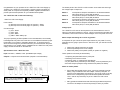
IMPORTANT SAFETY INSTRUCTIONS
1. All the safety and operating instructions should be read before this
product is operated. Keep these instructions for future reference.
2. Pay attention to all warnings on the power supply and in the operating
instructions.
3. WARNING: Do not use this device near water or any other liquid.
4. Clean only with dry cloth.
5. Do not block any ventilation openings.
6. Do not use this device near any heat sources.
7. Do not remove the power plug grounding pin on the input cable.
8. Protect all input and output power cables from being walked on or
pinched.
9. Only use attachments/accessories specified by the manufacturer.
10. Use only with the brackets and screws provided with this power
supply.
11. Unplug this device during lightning storms or when unused for long
periods of time.
12. Refer all repairs to qualified personnel at Truetone or an authorized
Truetone distributor. Under no circumstances should the power
supply be opened by the user.
13. This lightning flash with arrowhead symbol within an equilateral
triangle is intended to alert the user to the presence of non-insulated
“dangerous voltage” within the product’s enclosure that may be of
sufficient magnitude to constitute a risk of electric shock.
Owners Manual
- WARNING: To reduce the risk of electric shock, do not remove cover
(or back) as there are no user-serviceable parts inside. Refer
servicing to qualified personnel.
- The exclamation point within an equilateral triangle is intended to
alert the user to the presence of important operating and
maintenance instructions in the literature accompanying the
appliance.
14. The maximum ambient temperature should not exceed 35 degree C.
15. Date code: YYMM, YY means year, MM means month. For example:
1412 represents Year 2014, December.
www.Truetone.com
Mounting your 1 SPOT Pro under a Pedaltrain® pedalboard:
The 1 SPOT Pro comes with 2 metal brackets, 4 black machine screws and 4
silver thread-forming screws. The black machine screws are for attaching the
metal brackets to the sides of the 1 SPOT Pro, and the thread-forming screws
are for attaching the brackets to the Pedaltrain®, as shown below. There is no
need to pre-drill holes for the screws if you are using a powered screwdriver.
Need some great pedals to go
with your 1 SPOT Pro?
Check out Truetone* pedals at
Truetone.com
* Truetone was formerly known as Visual Sound; the makers
of Jekyll & Hyde, Route 66, H2O, Visual Volume andH
The 1 SPOT!
Make sure the 1 SPOT Pro is
slanted during mounting, so that
the IEC input socket is in between the
rails of the Pedaltrain. To help position it
correctly, you can put a 9V battery under the
1 SPOT Pro (center-back of the unit), which
will raise the back to the proper heightH the
battery is only acting as a temporary spacer.
After the 4 thread-forming screws are installed, push the 9V battery out.
Congratulations on your purchase of the 1 SPOT Pro CS7 Power Supply by
Truetone! The 1 SPOT Pro CS7 provides 7 outputs to power just about any
effect pedal. All 7 outputs are completely isolated, regulated, and filtered to
provide quiet and safe operation for your valuable effects pedals.
The bottom panel of the 1 SPOT Pro CS7 contains 4-mini switches that change
the voltage output of outputs 2-5.
The 1 SPOT Pro CS7 contains the following:
Switch 2
1 SPOT Pro CS7 Power Supply
Switch 3
Power cables:
(4) DC18 (5.5x2.1mm barrel plugs; 18” (457mm) – White
(3) DC12 (5.5x2.1mm barrel plugs; 12” (305mm) – Yellow
Switch 4
Switch 1
corresponds to Output-2 and allows it to be switched between
either 9Vdc (OFF) or 12Vdc (ON) at 200mA
corresponds to Output-3 and allows it to be switched between
either 9Vdc (OFF) or 12Vdc (ON) at 200mA
corresponds to Output-4 and allows it to be switched between
either 9Vdc (OFF) or 12Vdc (ON) at 200mA
corresponds to Output-5 and allows it to be switched between
either 9Vdc (OFF) or 12Vdc (ON) at 200mA
Voltage Input:
Converter Plugs:
(1) CL6 – Green
(1) CYR – Red
(1) C35 – Black
(1) CBAT – Black battery clip
The 1 SPOT Pro CS7 can be used anywhere in the world without the use of a
step-up or step-down transformer. Like our 1 SPOT, it transforms wall voltage from
100-240Vac, and converts it into the stated voltages on the front panel on the unit.
Which output and settings do I use for my pedals?
The proper powering of effects pedals is much misunderstood, but necessary
knowledge that every effect user must have. It is the difference between proper
functionality of your pedal, or potentially damage to it. To properly use the 1
SPOT Pro CS7 along with your effects devices, you must know both the power
requirements of your pedals, and the capabilities of the 1 SPOT Pro CS7 power
supply. We will concentrate on the latter first.
Specifications of the 1 SPOT Pro CS7:
Input: 100-240V~, 50/60Hz, 0.55A (Worldwide input voltage)
Outputs: 7 Outputs are as shown below: (Outputs 2-5 are switchable)
It is important for you to know the power requirements for your pedal. For every
pedal that you are going to power via the 1 SPOT Pro CS7, you need to know the
following:
1. What is the voltage required by the pedal?
2. Does the pedal require AC or DC voltage?
3. What is the polarity of the pedal? (Center pin positive or negative.)
These questions can usually be answered by:
1. Inspecting the pedal itself near the power jack.
2. Referring to the owner’s manual.
3. Checking online, or contacting the manufacturer
4. If your pedal can be powered by a 9Vdc battery, it can be powered by one
of the 9Vdc outputs (exception being the Boss ACA pedals, see below).
Notes on certain pedals:
1
2
Note: This symbol
indicates DC voltage.
3
4
5
6
•
Some older Boss pedals require 12Vdc, yet can be powered by a 9Vdc
battery. They will indicate “Use ACA adaptor” near the power jack. To
power an ACA pedal please use outputs 2-5, and set to 12Vdc on the dip
switch for the corresponding output. Modern Boss pedals will indicate
“PSA,” and can be powered by any of the 1 SPOT Pro CS7’s 9Vdc
outputs.
•
Many germanium based fuzzes and Octavia-style pedals will require the
use of the CYR adaptor to reverse the polarity to center pin positive.
7
Note: These numbers do not
appear on the actual unit.
•
•
For pedals with high milliamp draws such as Strymon please utilize outputs
6 or 7 that produce 500mA each.
Eventide pedals such as the Time Factor and H9 may be powered by
outputs 6 or 7 with the addition of the CL6 converter, for proper dc jack tip
size and polarity.
•
Line 6 M5 may be powered by outputs 6 or 7.
•
Line 6 M9, and the modeling pedals (DL-4/MM-4), may be powered by
outputs 6 or 7, and will also require the CL6 converter.
•
Line 6 Tone Core pedals may be powered by any 9Vdc output.
•
Line 6 POD or M13 cannot be powered by the 1 SPOT Pro CS7.
•
If more 9Vdc pedals need to be powered, a MC5 daisy chain (sold
separately) may be plugged into any of the 9Vdc outputs depending on mA
draw.
•
Pedals that do not utilize a power jack, yet are powered normally by a 9Vdc
battery, may utilize any 9Vdc output, along with the CBAT converter.
•
TC Electronic Nova pedals may be powered by outputs 2-5 in the 12Vdc
position.
•
TC Electronic Classic and Tone Print series may be powered by any 9Vdc
output.
•
Digitech Whammy: Versions 1-4 cannot be powered by the 1 SPOT Pro
CS7. Version 5 or Whammy DT may be powered by ouputs 6 or 7.
Warranty:
The 1 SPOT Pro CS7 carries a 5-year warranty to the original owner, covering
faulty materials and workmanship.
The warranty is considered void for any of the following reasons:
1. The unit has been modified in any way.
2. Any repair has been attempted by anyone other than the manufacturer.
If your unit becomes defective during the warranty period, please contact
Truetone to obtain a return authorization. All contact information can be found
at Truetone.com
WARNING: Operation contrary to the guidelines set forth in this manual may
damage your pedals. Truetone is not responsible for the damage of your
pedals by improper usage.
Input Power Cable:
Your 1 SPOT Pro includes an input power cable. Insert the universal IEC plug
into the socket on the back of the 1 SPOT pro. Plug the other end into a wall
outlet or power strip.
FCC Notice:
Note: This equipment has been tested and found to comply with the limits for a Class B digital
device, pursuant to part 15 of the FCC Rules. These limits are designed to provide reasonable
protection against harmful interference in a residential installation. This equipment generates, uses
and can radiate radio frequency energy and, if not installed and used in accordance with the
instructions, may cause harmful interference to radio communications. However, there is no
guarantee that interference will not occur in a particular installation. If this equipment does cause
harmful interference to radio or television reception, which can be determined by turning the
equipment off and on, the user is encouraged to try to correct the interference by one or more of the
following measures:
— Reorient or relocate the receiving antenna.
— Increase the separation between the equipment and receiver.
— Connect the equipment into an outlet on a circuit different from that to which the
receiver is connected.
— Consult the dealer or an experienced radio/TV technician for help.