1
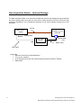
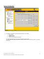
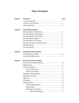
FISOCommander Bus Veloce Edition Software Operating Manual MAN-00035R11 If the equipment described herein bears the symbol, the said equipment complies with the applicable European Union Directive and Standards mentioned in the Declaration of Conformity. SAFETY INFORMATION The following safety instructions must be observed whenever the instrument is operated. Failure to comply with any of these instructions or with any precaution or warning contained in the conditioner Operating Manual is in direct violation of the standards of design, manufacture and intended use of the conditioner. In no case will FISO Technologies Inc. be liable to the buyer, or any third parties, for any consequential or indirect damage witch is caused by product failure, malfunction, or any other problem. DISCLAIMER Information published in this manual is believed to be accurate and reliable. However, FISO Technologies assumes no responsibility for the use of such information. FISO Technologies reserves the right to make revisions or changes to any parts of this manual or to the software described herein at any time without obligation to notify of these changes. WARRANTY INFORMATION FISO Technologies warrants that the software sold has been designed in good workmanlike and proper manner; that it will perform according to the specifications if used in compliance with the guidelines provided; that when shipped, it will be fully functional, free from any defects in either workmanship or material; and that, for a period of one year from the date of delivery, we will repair or replace without cost any part that may prove to be defective. All computers and computer components (acquisition card), known as per the terminology «computer station», provided by FISO Technologies are warranted for the same period and conditions as their respective original manufacturer warranty. In case of repair requirement, items must be returned to FISO Technologies factory location with the RMA authorization. FISO Technologies’ support will be limited to the applications originally provided. FISO Technologies is not responsible for the lost of data and softwares installed by the customer. © Copyright 2003. FISO Technologies inc. MAN-00035 R10 FISOCommander BusVeloce Edition Software User’s Manual ii TABLE OF CONTENTS Welcome in FISOCommander Bus/Veloce Edition® ....................................................................................4 Introduction .................................................................................................................................................................................................. 4 System requirements................................................................................................................................................................................... 4 Minimum requirements................................................................................................................................................................. 4 System recommended ................................................................................................................................................................. 4 System recommended for high-speed analog acquisition ........................................................................................................... 4 Data Acquisition Station – Optional Package .............................................................................................................................................. 5 FISOCommander Bus/Veloce Edition: Bus windows description .............................................................6 Main window ................................................................................................................................................................................................ 6 Chassis configuration .................................................................................................................................................................................. 7 System Configuration .................................................................................................................................................................................. 8 Gage Configuration ..................................................................................................................................................................................... 9 Analog Output and Acquisition Configuration............................................................................................................................................ 10 RS-232 Acquisition .................................................................................................................................................................................... 11 Analog Output Card - Optional .................................................................................................................................................................. 13 Analog Output Card Configuration ............................................................................................................................................. 13 Normal Chart Mode.................................................................................................................................................................... 14 FISOCommander Bus/Veloce Edition: Veloce windows description.................................................15 Main window .............................................................................................................................................................................................. 15 Chassis configuration ................................................................................................................................................................................ 16 Analog Output and Acquisition Configuration............................................................................................................................................ 18 Analog Output Card – Optional ................................................................................................................................................................. 20 Normal Chart Mode.................................................................................................................................................................... 22 Fast Chart Mode ........................................................................................................................................................................ 23 Operation basis .............................................................................................................................................24 How to replace a sensor ............................................................................................................................................................ 24 Acquisition ................................................................................................................................................................................................. 24 How to make an acquisition ....................................................................................................................................................... 24 How to increase/decrease the rate ............................................................................................................................................ 24 How to do averaging .................................................................................................................................................................. 24 ® How to open a text file and analyze it with Excel ...................................................................................................................... 24 Troubleshooting ............................................................................................................................................25 How to verify you RS-232 cable................................................................................................................................................. 25 How to verify the RS-232 port .................................................................................................................................................... 25 Re-Installation procedure ........................................................................................................................................................... 25 Frequently asked questions.........................................................................................................................26 Reference .......................................................................................................................................................27 RS-232 Syntax & Commands .......................................................................................................................27 iii Welcome in FISOCommander Bus/Veloce Edition® Introduction FISOCommander Bus/Veloce Edition® software is designed to help the developers in their daily objectives. Combined with the Bus or the Veloce conditioner, it provides an easier visualization of the functions, and ensures a quick access to all your parameters setting. The FISOCommander Bus/Veloce Edition® software will be of great help to ensure a continuous progress in your tests or developments. Dynamic sampling of the data. Analog output configuration. Rate and Average configuration. Export function for external data analysis. Save the data in spreadsheet software like Microsoft Excel® or Corel Quattro® format for further analysis. This software manual is an extension of your conditioner manual. FISO Technologies highly suggest its customers to read the conditioner manual for a better understanding of their whole system. System requirements Minimum requirements Microsoft® Windows® 95, 98, 2000NT or XP. Monitor with a 800 X 600 resolution 233 MHz Intel PentiumTM Minimum 64 megabytes RAM 20 MB hard disk space System recommended Microsoft® Windows® 2000NT 300 MHz Intel Pentium llTM 128 megabytes RAM. 40 MB hard disk space System recommended for high-speed analog acquisition Microsoft® Windows® 2000NT 1.5 GHz Intel Pentium lVTM 256 megabytes RAM. 500 MB hard disk space © Copyright 2003. FISO Technologies inc. MAN-00035 R10 FISOCommander BusVeloce Edition Software User’s Manual 4 Data Acquisition Station – Optional Package The Data Acquisition Station is an extension package that monitors and displays the high speed BUS and Veloce analog output, and gives an easy way to quickly generate an Excel file from the tests performed. Depending if you purchased this extension or not, some software modules may not be accessible. RS-232 Computer with PCMCIA or PCI NIDAQ card Bus / Veloce System Analog output BNC 2090 Module OR Acquisition card Ribbon cable BNC Cable Quick Start: Make the connections as described above. Turn-on your computer. ® In the program files, launch the FISOCommander Bus/Veloce Edition software. Make a test! 5 © Copyright 2003. FISO Technologies5inc. MAN-00035 R10 FISOCommander BusVeloce Edition Software User’s Manual FISOCommander Bus/Veloce Edition: Bus windows description FISOCommander Bus/Veloce Edition® is compatible only with eprom version of Bus System from 3.42 upward. Previous version of eprom should use the BUS-Link software. Eprom upgrade is possible by returning the system to the factory. Please contact our technical support for assistance. FISOCommander Bus/Veloce Edition® software is divided into different windows. In the coming pages we made screenshots of each window, and added a description of the different functions available, in order to facilitate the user understanding. Main window 1. In the main window of FISOCommander Bus/Veloce Edition®, select your computer Communication Port used to establish the serial link (RS-232). 2. Precise the conditioner model (Bus) and click Add. © Copyright 2003. FISO Technologies inc. MAN-00035 R10 FISOCommander BusVeloce Edition Software User’s Manual 6 Chassis configuration 3. Make the configuration following the number of modules and their position. From left to right, modules are labeled as position #1 to #8. 4. When completed, click on "Test module connection". The window "Successful configuration" will appear. If the window does not appear, please refer to the "Troubleshooting" section at the end of this manual. 7 © Copyright 2003. FISO Technologies 7 inc. MAN-00035 R10 FISOCommander BusVeloce Edition Software User’s Manual System Configuration 5. The system’s configuration window provides information on the module: Serial Number Hardware Version Software Version Type of units (international or imperial) This window also allows the user to turn on/off the lamp of each module. The reset buttons are used to reinitialize the memory content of the desired Bus module to the default state values. © Copyright 2003. FISO Technologies inc. MAN-00035 R10 FISOCommander BusVeloce Edition Software User’s Manual 8 Gage Configuration SELECT GAGE 6. For each module, select the proper gage. You can also add or delete a gage from the gage list. GAGE OFFSET 7. The «Gage Offset» section is used to define a zero value to a relative sensor. If the user wants the sensor’s actual exposure to become the zero position (in physical unit), simply click on «Null» button. If the user wants to force a reading to the actual sensor condition, simply click «Physic» and type in the value physical unit. For advanced users, if desired, an offset in internal units (nanometers) may be directly entered in the type-in box by the user. 8. For each module, you could verify the gage diagnostic. For more information on the diagnosis feature, see the Bus System user's manual, section 4.1. 9 © Copyright 2003. FISO Technologies 9inc. MAN-00035 R10 FISOCommander BusVeloce Edition Software User’s Manual Analog Output and Acquisition Configuration SCALE AND ZERO VALUE 9. Set the desired analog output scale factor in mV / physical unit. 10. Set the desired analog output zero value in physical unit. SPEED, AVERAGE AND RATE 11. Set the analog output acquisition speed, average and rate values. Note that the average cannot be smaller than one time the speed, and that the rate cannot be smaller than the average. For more information, refer to the Bus System user's manual. AUTO-ACQ 12. The Auto-Acq. checkmark is activated by default. When the user modifies a parameter in this window, the Bus System will stop the acquisition, calculate its internal parameters, and restart automatically the acquisition. This processus can be long if you want to modify more than one of the parameter. Therefore, you could disable the auto-acquisition during the time you do your modification, and reactivate it after. © Copyright 2003. FISO Technologies inc. MAN-00035 R10 FISOCommander BusVeloce Edition Software User’s Manual 10 RS-232 Acquisition 13. This window displays the acquisition speed, average and rate for each module. Set the number of desired data for the acquisition. Note that the number of data is limited to 4096. The data are stored in a circular memory, so the system will store the number of data desired in a continuous way until the acquisition is stopped. The approximate delay for the acquisition is shown. To start the acquisition, press the "Start" button. To display the results, press the "Display" button. 11 © Copyright 2003. FISO Technologies 11inc. MAN-00035 R10 FISOCommander BusVeloce Edition Software User’s Manual 14. This window shows the actual configuration information. Press the "Download" button to download the data from the buffer. To save the downloaded data in .csv file, press "Save" button. To return to the previous window, press "Back" button. The download time may take up to 5 minutes. For measurement verification and faster download, simply reduce the number of data collected in the previous windows. © Copyright 2003. FISO Technologies inc. MAN-00035 R10 FISOCommander BusVeloce Edition Software User’s Manual 12 Analog Output Card - Optional The analog acquisition features integrated in FISOCommander Bus/Veloce Edition®, are available only if you purchased the «Data Acquisition Station» optional package. If you purchased the «Data Acquisition Station», the following section will be preconfigured at factory onto the laptop provided. If the software ever needs to be registered again, simply click on the "?" button on the top right of the window to unlock the Analog Output Card functionality. A registration window will appear allowing you to enter your registration number, provided with your package. Analog Output Card Configuration AO Card Info 15. This box provides information from the National Instrument Card. If you are using several acquisition cards, make sure to select the proper one that corresponds to the Bus System. Four (4) different National Instruments cards are available, PCI-6034E, PCI-6035E, PCI-6071E, PCMCIA DAQCard-AI-16E-4. Acquisition Configuration (Normal Mode) 16. The normal mode offers real time display up to 10 kHz (note that the Bus System is limited to 1 kHz). It is also where the user must specify the Acquisition Duration. For all acquisition, a text file is generated and, at his convenience, the user may disable the graph plotted at the computer screen. Channel Configuration 17. This box contains all the settings for the real time display function available. For each channel, the user may assign a precise color. According to specific needs, one specific channel can be enabled or disabled by adding and removing the checkmark. When checked, the «Bus module bay association» will recall the corresponding setting to save module configuration in the text file. 13 © Copyright 2003. FISO Technologies 13inc. MAN-00035 R10 FISOCommander BusVeloce Edition Software User’s Manual File Configuration 18. This box contains all the settings for generating a text file. In the text file, the data will display in columns. Each column contains data corresponding to one channel/sensor. For easiest export to Excel®, we recommend to separate the columns by a tab, and to separate the decimals with a dot. This configuration makes the export to Excel® software easy to perform. 19. During the acquisition, the system generates a binary file that is unreadable. Its name is the selected file name excepted that it finishes by a “~”, for example “Filename.txt~”. When the acquisition is finished or when the user clicks on “stop” button in the graph window, the generated file is post-processed (all information are converted in ascii characters and the binary file is deleted). In the case where the software communication fails during the acquisition, the generated file is not post-processed and its name finishes by a “~”, this indicates that the file is still in binary. The user can then launch the post-processing by clicking the button “file recovery” to obtain the text file for the acquisition. 20. The text file generated can be saved under a fixed name or under an automated name generator. If you select «fixed filename», the software will ask a filename once the user press start for acquisition. The file will be saved in the folder specified by the user. The automatic file generator prevents to overwrite on an existing file. The filename will be generated from the date and time of the acquisition. Normal Chart Mode Normal Chart Mode This visual plotting is generated to ensure normal process of the acquisition. For advanced graphic generation, we recommend to export data in spreadsheet software. © Copyright 2003. FISO Technologies inc. MAN-00035 R10 FISOCommander BusVeloce Edition Software User’s Manual 14 FISOCommander Bus/Veloce Edition: Veloce windows description FISOCommander Bus/Veloce Edition® software is divided into different windows. In the coming pages we made screenshots of each window, and added a description of the different functions available, in order to facilitate the user understanding. Main window 1. In the main window of FISOCommander Bus/Veloce Edition®, select your computer Communication Port used to establish the serial link (RS-232). 2. Precise the conditioner model (Veloce) and click Add. 15 © Copyright 2003. FISO Technologies 15inc. MAN-00035 R10 FISOCommander BusVeloce Edition Software User’s Manual Chassis configuration 3. Make the configuration according to the number of modules and their position. From left to right, modules are labeled as position #1 to #8. 4. When completed, click on «Test module connection». The window "Successful configuration" will appear, and then you will be able to access to the other configuration windows. If the window does not appear, please refer to the "Troubleshooting" section at the end of this manual. © Copyright 2003. FISO Technologies inc. MAN-00035 R10 FISOCommander BusVeloce Edition Software User’s Manual 16 System Configuration 5. The system’s configuration window provides information on the module: Module serial number Hardware version Software version Last date of calibration 6. It is also possible to export calibration parameters in text file for advanced use. 17 © Copyright 2003. FISO Technologies 17inc. MAN-00035 R10 FISOCommander BusVeloce Edition Software User’s Manual Analog Output and Acquisition Configuration SENSITIVITY 7. Enter your sensor’s sensitivity (in nm / unit). Note that the default sensitivity is 1.000 nm / unit. CALCUL (GAGE FACTOR) 8. Enter in this option only if you have access to the gage factor of your transducer. The screen will automatically calculate the sensitivity using your gage factor. a. Enter gage factor (7 digits) b. Click on “Calcul” button to display the appropriate sensitivity, or on “Apply” to set the sensitivity of the current module. © Copyright 2003. FISO Technologies inc. MAN-00035 R10 FISOCommander BusVeloce Edition Software User’s Manual 18 Note: With “temperature” and “refractive index” gage the system is unable to calculate the sensitivity. In these cases, the user must perform his own calibration using a reference sensitivity of 1.000 nm / units. ANALOG OUTPUT SCALE (mV / Unit) 9. Set the analog output scale factor desired. SPAN 10. According to the «Analog Output Scale» setting described above, the software will automatically calculate a new SPAN factor for the conditioner. The user does not have access to change this setting. NULL 11. Press the null buttons for zeroing the module analog output. RESET 12. Press the reset buttons for zeroing your fiber optic sensors. Front plate RESET: The front plate RESET activates the lamp re-calibration, and then zeroes the gage. Software RESET: The software RESET simply zeroes the gage, which is recommended for multiple routine test. AVERAGE 13. Set the speed and average value. Note that the speed and average features are controlled via one parameter. The slower the Rate is, the more Averaging the system will perform. DIAGNOSTIC 14. Read signal diagnostic for current Veloce module. 19 © Copyright 2003. FISO Technologies 19inc. MAN-00035 R10 FISOCommander BusVeloce Edition Software User’s Manual Analog Output Card – Optional The analog acquisition features integrated in FISOCommander Bus/Veloce Edition®, are available only if you purchased the «Data Acquisition Station» optional package. If you purchased the «Data Acquisition Station», the following section will be preconfigured at factory onto the laptop provided. If the software ever needs to be registered again, simply click on the "?" button on the top right of the window to unlock the Analog Output Card functionality. A registration window will appear that allowing you to enter your registration number, provided with your package. AO Card Info 15. This box provides information from the National Instrument Card. If you are using several acquisition cards, make sure to select the proper one that corresponds to the Veloce conditioner. Four (4) different National Instruments cards are available, PCI-6034E, PCI-6035E, PCI-6071E, PCMCIA DAQCard-AI-16E4. Acquisition Configuration (Normal Mode) 16. The normal mode offer real time display up to 10 kHz. It is also where the user must specify the Acquisition Duration. For all acquisition, a text file is generated and, at his convenience, the user may disable the graph plotted at the computer screen. Acquisition Configuration (Fast Mode) 17. This box is similar to the normal mode. The main exception is that the acquisition speed available is larger. The acquisition can be performed at a speed of 10 kHz – 200 kHz. Due to the higher sampling rate, the graph plotting parameters are different in order to ensure system reliability. © Copyright 2003. FISO Technologies inc. MAN-00035 R10 FISOCommander BusVeloce Edition Software User’s Manual 20 Channel Configuration 18. This box contains all the settings for the real-time display function available (Slow or Fast mode). For each channel, the user may assign a precise color. According to specific needs, one specific channel can be enabled or disabled by adding and removing the checkmark. When checked, the «Veloce module bay association» will recall the corresponding setting to save module configuration in the text file. File Configuration 19. This box contains all the settings for generating a text file. In the text file, the data will display in columns. Each column contains data corresponding to one channel/sensor. For easiest export to Excel®, we recommend to separate the columns by a tab, and to separate the decimals with a dot. This configuration makes the export to Excel® software easy to perform. 20. During the acquisition, the system generates a binary file that is unreadable. Its name is the selected file name except that it finishes by a “~”, for example “Filename.txt~”. When the acquisition is finished, or when the user clicks on “stop” button in the graph window, the generated file is post-processed (all information are converted in ASCII characters and the binary file is deleted). In the case where the software communication fails during the acquisition, the generated file is not post-processed, and its name finishes by a “~”. This indicates that the file is still in binary. The user can then launch the post-processing by clicking the button “file recovery” to obtain the text file for the acquisition. 21. The text file generated can be saved under a fixed name or under an automated name generator. If you select «fixed filename», the software will ask a filename once the user presses start for acquisition. The file will be saved in the folder specified by the user. The automatic file generator prevents to overwrite on an existing file. The filename will be generated from the date and time of the acquisition. 21 © Copyright 2003. FISO Technologies 21inc. MAN-00035 R10 FISOCommander BusVeloce Edition Software User’s Manual Normal Chart Mode Normal Chart Mode 22. This visual plotting is generated to ensure normal process of the acquisition. For advanced graphic generation, we recommend to export data in spreadsheet software. © Copyright 2003. FISO Technologies inc. MAN-00035 R10 FISOCommander BusVeloce Edition Software User’s Manual 22 Fast Chart Mode Fast Chart Mode 23. Due to the higher speed, the visual plotting is generated faster to ensure reliability of the system. Also, make sure to start the acquisition just before the event. Take note that long acquisition at high speed rate generates heavy file on your hard drive. For example, a 200 kHz rate acquisition of 10 seconds long will generate a 2.5 Mo file. Note that, for example, Microsoft® Excel® software cannot open file of more than about 65000 data. Examples: Duration : 1 minutes Channel (s) Speed 1 200kHz 2 100kHz 4 50kHz 10 20kHz 16 10kHz 23 AI Card : PCI-6035E (FAST Graph mode) Temporary file Text file Post-Process duration 47 meg 262 meg 3 min 20 sec 47 meg 192 meg 2 min 11 sec 47 meg 159 meg 1 min 37 sec 47 meg 146 meg 1 min 21 sec 38 meg 122 meg 58 sec © Copyright 2003. FISO Technologies 23inc. MAN-00035 R10 FISOCommander BusVeloce Edition Software User’s Manual Operation basis How to replace a sensor 1. 2. 3. Remove your transducer from its box, and connect it to the selected channel. To establish a good connection between the conditioner and the transducer, follow the key way on the transducer connector, and make sure to lock it to the conditioner. In FISOCommander Bus/Veloce Edition® software, go to the «AO & Acquisition Configuration». At the gage factor box, type-in the new gage factor. Before making an acquisition, it is a good habit to verify that the gage factor assigned to each module is the proper one. Also, make sure that the acquisition space required for saving data does not exceed the computer capacity. Acquisition How to make an acquisition 1. 2. 3. 4. 5. 6. 7. Connect a sensor. Make sure the Gage Factor is the proper one. If required, set your Analog Output Scale and Average (Rate) Select the mode desired, and type in the acquisition duration and the sampling rate desired. Go in the Slow mode, and press Start. Data are saved in a text file format on your hard drive. Browse your hard drive to retrieve the file. How to increase/decrease the rate 1. Go in the «AO & Acquisition Configuration». 2. In the Rate box, type in a new value. The Rate value is expressed is seconds. It represents the time between two outputs. How to do averaging 1. Averaging feature may be helpful to eliminate noise and improve system accuracy. The averaging & rate is one parameter and should be set to the best compromise. How to open a text file and analyze it with Excel® 1. 2. 3. 4. Load Excel® program. In the File menu select Open. At the open window, select the file type: (*.txt). Select the folder containing the text file. © Copyright 2003. FISO Technologies inc. MAN-00035 R10 FISOCommander BusVeloce Edition Software User’s Manual 24 Troubleshooting How to verify your RS-232 cable RS-232 cables are rarely the source of a problem, but most of the time they are confused or replaced by null modem cable. Conditioner-Computer link requires RS-232 standard cable. Modem-Conditioner link requires RS-232/Null Modem cable. If it is a standard RS-232 cable...what you need. Pin 2 is linked to Pin 2 Pin 3 is linked to Pin 3 RS-232/Null Modem cable connections…what you should avoid. Pin 2 is linked to Pin 3 Pin 3 is linked to Pin 2 How to verify the RS-232 port Occasionally, RS-232 ports are subjected to unpredictable defects. The quickest way to verify the port is via a test with another conditioner, or equipment, that requires the use of the RS-232 port. Re-Installation procedure Laptop package, recovery steps: 1. 2. 3. This procedure will format the computer hard drive. Data and program installed on the computer will be deleted. Prior to proceed to this operation, make sure that you have a copy of all important files. Insert the Recovery CD-ROM. Reboot your computer. FISO Technologies package, re-installation steps: 1. 2. 3. 4. 5. 6. 7. 25 From the CD FISO_SOFT provided by FISO, install the National Instrument driver for acquisition card. Once completed, turn off your computer, and install the National Instrument data acquisition card in your computer. Restart your computer; Windows® should recognize the card. From the CD FISO_SOFT provided by FISO, install the FISOCommander Bus/Veloce Edition® software. Link your computer communication port to the conditioner serial connector, using the provided RS-232 cable. Reboot your computer, and scroll in the program file to launch the application. Link the computer to the BNC junction box, and from the junction box to the conditioner Analog Output. Connect your sensor to the conditioner Sensor input. © Copyright 2003. FISO Technologies 25inc. MAN-00035 R10 FISOCommander BusVeloce Edition Software User’s Manual Frequently asked questions Q.: Why is it impossible to install the software? Make sure to uninstall previous software before to install a new one. Q.: Why is the software unable to detect the conditioner or a module? Verify if the conditioner is well connected to the computer with a standard RS-232 cable supplied with your conditioner. Pay attention not to use a RS-232 Null-Modem cable, required for modem application. Make sure that each module is well connected. Q.: Why is Excel® unable to open the text file? If there is a “~” at the end of the file name, click on “File Recovery” in the Config. window to launch the post-processing of the file. Also, note that spreadsheet software like Excel® are limited to about 65000 data or 150 Mo files. Q.: What is « FISO1000 » or «0001000» gage factor? « FISO1000 » cannot be deleted; it is a default gage factor from FISO which provide measurements in nanometers (internal unit). © Copyright 2003. FISO Technologies inc. MAN-00035 R10 FISOCommander BusVeloce Edition Software User’s Manual 26 Reference Reflection: Property of light. As opposed to transmission, the light makes its way back from where it is coming. RS-232: Serial communication establish for electronic communication. The RS-232 port is normally a standard device on any computer. RS-232 Syntax & Commands RS-232 commands are listed at the end of your conditioner user's manual. 27 © Copyright 2003. FISO Technologies 27 inc. MAN-00035 R10 FISOCommander BusVeloce Edition Software User’s Manual