Download User Manual - Future Design Controls

Transcript
User Manual
Paperless Recorder VR06
Future Design Controls, Inc.
7524 West 98th Place
Bridgeview, IL 60455
888.751.5444 - Office:
888.307.8014 - Fax
866.342.5332 - Technical Support
http://www.futuredesigncontrols.com/
VR06 Manual – v2.37 – November 2011
FDC-UMVR061C
Page
Contents
Safety --------------------------------------------------------------------------------Safety Symbols -------------------------------------------------------------------------Safety Notes and Precautions ---------------------------------------------------------Static Electricity -----------------------------------------------------------------------
1. General Description -------------------------------------------------------------------1.1
1.2
1.3
1.4
1.5
1.6
1.7
1.8
Unique Features of Recorder ------------------------------------------------------Expandable Input and Output cards -----------------------------------------------Communication -----------------------------------------------------------------------Storage Media CF card ----------------------------------------------------------------Data Security -------------------------------------------------------------------------Infrared Detector --------------------------------------------------------------------Ordering Codes and Accessories -------------------------------------------------Specifications -------------------------------------------------------------------------
2. Installation and wiring ----------------------------------------------------------------2.1
2.2
2.3
2.4
2.5
2.6
Unpacking -------------------------------------------------------------------------------Installation -------------------------------------------------------------------------------Setup Input, Output & 24VDC power supply cards -----------------------------Wiring of the cards -------------------------------------------------------------RS-232, RS-422, RS-485 wiring --------------------------------------------------Installation of Compact Flash CF Card -----------------------------------------------
3. Basic Operation --------------------------------------------------------------------------3.1
3.2
3.3
3.4
3.5
3.6
3.7
3.8
3.9
3.10
3.11
3.12
Page ------------------------------------------------------------------------------Mode -----------------------------------------------------------------------------History ------------------------------------------------------------------------------Event ----------------------------------------------------------------------------Status ------------------------------------------------------------------------------Exit --------------------------------------------------------------------------------Dump -----------------------------------------------------------------------------Clear ------------------------------------------------------------------------------Operate ---------------------------------------------------------------------------Shutdown ------------------------------------------------------------------------Logout -----------------------------------------------------------------------------------Small Icons ------------------------------------------------------------------------
4. Configuration -------------------------------------------------------------------4.1
4.2
4.3
4.4
4.5
4.6
Channel (Analog input, Digital input, Analog output, Math input) -----------Display --------------------------------------------------------------------------Tools (Timer, Counter & Totalizer) ------------------------------------------------Instrument ------------------------------------------------------------------------Clock --------------------------------------------------------------------------------------Normal Security & High Security with CFR-21 part 11 type features----------- - - - - - - - - - - - - - - - - -
FDC-VR06_Manual_V2.37_November-2011.doc
2
4
4
4
5
6
6
6
6
7
7
7
8
11
14
14
14
21
23
26
28
29
29
30
31
32
33
33
34
34
34
34
34
35
36
37
43
45
50
53
54
4.7 Demo -------------------------------------------------------------------------4.8 System Info -----------------------------------------------------------------------------4.9 Configuration Example --------------------------------------------------------------
55
55
56
Observer I & Observer II PC software guide -----------------------------Ethernet Configuration -----------------------------------------------------RS 232, RS485, RS422 Configuration -----------------------------------------------CF card Configuration ------------------------------------------------------Configuration in Real-Time Viewer --------------------------------------------DDE dynamic data exchange ---------------------------------------------
57
57
61
65
70
72
76
6. Application examples --------------------------------------------------------------------
82
7. Trouble shooting --------------------------------------------------------------------------
85
8. FAQs frequently asked questions --------------------------------------------------
88
5. PC software and Communication configuration ---------------------------5.1
5.2
5.3
5.4
5.5
5.6
FDC-VR06_Manual_V2.37_November-2011.doc
3
Safety
This recorder is compliant with the requirements of:
CE: EN61010-1
UL: 61010C-1
CSA: C22.2 No. 24-93. file #209463
The protection provided by the recorder may be impaired if it is used in a manner inconsistent with its
intended purpose, or in an environment that exceeds the specifications of the recorder. Future Design
Controls, Inc. is not liable for customer’s failure to comply with these requirements.
Safety Symbols
The following symbols may be seen on the user manual or recorder labeling.
Caution
Protective Earth
DC Supply
FDC-VR06_Manual_V2.37_November-2011.doc
4
Safety Notes and Precautions
1. The protective earth terminal should be connected first before any other connection is made. To avoid
making the recorder dangerous under fault conditions, any interruption of the protective Earth conductor
inside or outside the recorder is prohibited. Even in the case of a portable unit, the protective earth
terminal must remain connected if the recorder is connected to any hazardous voltages.
2. Keep signal and supply voltage wiring separated from one another. If this is impractical, use shielded
cables for signal wiring. Double insulation should be used for signal wiring when the recorder is being
used with hazardous voltage.
3. Do not use the recorder where there is high vibration, or high magnetic field, this could cause damage or
error of measurement.
4. All maintenance or repairs should be carried out with power disconnected, to avoid personal injury, or
damage to the unit.
5. In areas with conductive pollution, adequate ventilation, filtering and sealing need to be installed.
6. When cleaning the recorder, handle carefully and use soft dry cloth. Avoid the use of abrasives or any
sharp and hard objects, which would damage the display.
7. Do not operate the recorder if any part has been removed or disassembled. Consult your nearest dealer
at once.
Static Electricity
Appropriate precautions must be taken when handling the recorder. The circuit board, components are
susceptible to damage caused by electrostatic discharge. Take static electricity precautions when handling
and inserting Compact Flash Card into the recorder.
To replace the power-line fuse
The power-line fuse is located within the fuse-holder on the power board. For 90-250 VAC line voltages,
the user must use a 2.5A/250VAC time-lag fuse, and for both 11-18 VDC and 18-36 VDC line voltages, a
5.0A/250VAC time-lag fuse must be used.
FDC-VR06_Manual_V2.37_November-2011.doc
5
1. General Description
1.1 Unique features of recorder
The VR06 is a well-designed paperless recorder with many outstanding features including:
• 6.4” TFT Color LCD with VGA Display; 640 x 480 pixel resolution, 256 colors.
• 1 to 6 isolated Analog Inputs
• Plug & play I/O cards for easy expansion
• Simple and friendly operation
• Infrared detector to prolong lifetime of LCD
• Solid state Compact Flash [CF] storage media; 1GB standard
• 6.0” [174 mm] short depth
• Ethernet as standard and optional RS-232/422/485 communication
• High accuracy 18-bit A-D Analog Input
• 15-bit D-A Analog Output.
• 200-millisecond sample rate per channel.
• Bench top with convenient portable handle, easy converted into panel mount
1.2 Expandable Input and Output Cards
The recorder is equipped with six-rear expansion slots, which work flexibly with the following plug & play
I/O cards. Any combination up to quantity of 6 cards may be used.
Analog Input cards (part number Series AI181, AI182, AI183): These three cards are available with 1, 2,
& 3-channel analog inputs. Each analog input is isolated from all other I/O. Analog input is configured by
DIP-switches and jumpers on the card before plugging into rear expansion slot. Refer 2.3 Setting Input
and Output Cards.
Analog Output cards (AO183I, AO183V): Each card includes 3 outputs. AO183I is used for 4-20mA, 020mA current output, and AO183V is used for 0-5V, 1-5V, 0-10V voltage output.
Digital Input card (DI181): Each card includes 6 inputs. Logic Low: -5V minimum, 0.8V maximum,
Logic High: -2V minimum, 5V maximum
Digital Output card (DO181): Each card includes 6 alarm relays. Contacts are rated 5 Amp/240 VAC
Power Supply Card (AP181): 24VDC 180mA power supply board for auxiliary devices. Each board
supports up to six-24VDC signals @30mA each. Each board is isolated from other I/O option boards.
1.3 Communication
The standard communication interface is Ethernet with protocol IEEE 802.3 - 10 Base T.
Optional RS-232 / RS-422 / RS-485 Modbus RTU is available.
FDC-VR06_Manual_V2.37_November-2011.doc
6
1.4 Storage Media CF Card
The Solid Compact Flash Memory Card (CF card) 1GB capacity is the standard storage media used for this
instrument. The CF card’s compact size, anti-dust and anti-vibration features provide high reliability.
To read measured data on CF Card, add a CF reader on USB port to your PC. Higher capacity 2GB CF
cards are available. Alternatively the user may purchase CF cards locally. To ensure compatibility, we
recommended only one brand SanDisk. If the recorder is used with 6-channel inputs, an easy chart to
show the maximum days CF can store the data.
CF card Memory Size:
Log speed
1 second
1GB
980 days
10 seconds
9,870 days
120 seconds
118,510 days
Each record of data uses 2 bytes of CF card memory. If the Log Speed (the recording speed of measured
data) is set to the fastest speed at 1 second per data, then for a single channel, 1GB CF card will last
approximately 5,920 days [= 1GB / (2 bytes x 24 hours x 60 minutes x 60 seconds].
The following formula is to calculate how many days the CF card could do saving before it is full.
The ? days = The capacity of CF Card /((2 bytes x # of channels) x (the Log Speed x the working hours
per day x 3600 seconds)/Log speed in seconds.
To avoid loss of recorded data while transferring data to PC, it is necessary to insert CF card back again
into the recorder soon after loading recorded data onto PC.
1.5 Data Security
The recorded data is stored in an encrypted binary format. It is not possible to manipulate or modify the
recorded data. This feature fully guarantees the security of the data.
1.6 Infrared Detector (IR Detector)
The use of Passive Infrared technology on the recorder is an innovative idea to prolong the lifetime of the
LCD display. The detector senses the movement of body heat from a distance of approximately 2 meters.
This feature works together with the Screensaver.
For example, if the IR Sensor is turned on and Screensaver set to 10 Min, the display will turn off 10
minutes after the user walks away from the recorder. The Passive Infra Red detects when the user returns to
the recorder and the display turns on straight away with no need to press any key on the recorder. The IR
Sensor used in conjunction with the screen saver is a user configured to be on or off.
FDC-VR06_Manual_V2.37_November-2011.doc
7
1.7 Ordering codes and accessories
Ordering codes
VR06 – □ □ □ □ – □ □ □ – □ □ □
1
2
3
4 – 5 6
7 –
8 9 10
1
Power
4: 90-250 VAC, 47-63 Hz
5: 20-28 VAC, 47-63 Hz
6: 11-18 VDC
7: 18-36 VDC
8: 36-72 VDC
2
Analog Input Card
0: none
1: 1 channel withAI181
2: 2 channels with AI182
3: 3 channels with AI183
4: 4 channels with AI181 & AI183
5: 5 channels with AI182 & AI183
6: 6 channels with AI183
G: 3 channels with AI183V
H: 6 channels with AI183V
*See AI181/2/3(V) for special analog input specifications in Accessories below.
3
Digital Input Card
0: none
1: 6 channels
4
Digital Output Card [5amps/240VAC]
0: none
1: 6 relays
5
Communication
0: standard Ethernet interface
1: RS-232/422/485 (three in one) + Ethernet interface
6
PC software
1: Free basic software Observer I for non-communication application
2: Extensive software Observer II for communication of RS-232/422/485 or Ethernet
7
Firmware
1: Mathematics, Counter, Totalizer & High Security CFR-21 part 11 type features
FDC-VR06_Manual_V2.37_November-2011.doc
8
8
Storage Media
6: 1 GB CF card (compact flash)
9
Case/Mounting
1: standard panel mounting, black case
2: Bench top / portable style with handle, USA power cable, black case
10 Special Option:
0: none
1: 24VDC auxiliary power supply (for transmitter, 6 channels)
2: 3-channel current output
3: 6-channel current output
D: 3-channel voltage output
E: 6-channel voltage output
5: panel mounting with rear power plug
6: panel mounting with front power switch
7: options 1 + 5
8: options 1 + 6
9: options 1 + 5 + 6
X: Consult Factory for other options or combination of options shown above
See Accessories & Notes on ordering components or model configurations not defined by matrix
above
FDC-VR06_Manual_V2.37_November-2011.doc
9
Accessories:
Part no.
Descriptions
AI181
AI182
AI183
AI183V
DI181
Analog Input - Single-channel analog input card
Analog Input - Dual-channel analog input card
Analog Input – Three-channel analog input card
Analog Input - Single-channel voltage input card (± mA, ± V, ± mV only)
Digital Input: 6-channel digital input card
AO183I
AO183V
DO181
Analog Output: 3-channel current output card
Analog Output: 3-channel voltage output card
Digital Output: 6-channel relay output card (AC/DC)
AP181
Power Supply: 24 VDC auxiliary power supply card for 6 transmitters
CM181
CM182
Communications Module: RS-232/422/485 + Ethernet communication module
Communication Module: Standard Ethernet communication module
PM181
PM182
PM183
PM184A
PM185
PM186
Power Module: 90-250 VAC, 47-63 Hz power supply
Power Module: 11-18 VDC power supply module
Power Module: 18-36 VDC power supply module
Power Module: 90-250 VAC, 47-63 Hz power supply with USA power plug
Power Module: 36-72 VDC 47-63 Hz power supply
Power Module: 20-28 VAC power supply
MK181B
MK183B
SC181
Enclosure: panel-mount assembly kit (black color)
Enclosure: bench top / portable handle assembly kit (black color)
Slot cover for an empty module slot
CF102
Compact Flash: 1GB compact flash card
AS181
AS182
SNA10A
Software: Basic PC software Observer I
Software: Extensive PC software Observer II
RS-485 to RS-232 converter; separate component from VR06
BT182
Boot ROM with Math, Counter, Totalizer & High Security with CFR-21 type features
FDCUMVR061C
VR06 User Manual v2.37 November 2011
Notes:
The rear slots of the recorder will only accept up to 6 optional cards/modules; these modules provide
analog or digital input, analog or digital output or 24 VDC power supply in any combination. For
example, 6-channel analog input needs 2 pieces of 3-channel analog input card AI183 with 4 empty
slots available for other cards.
Transmitter Power Supply module has 6 non-isolated 24VDC@30mA outputs.
Communication Module RS232/422/485 does not utilize an expansion slot.
The basic PC software Observer I is supplied free with recorder. There is an additional charge for the
extensive PC software Observer II for use with RS-232/422/485 or Ethernet communications.
The Ordering Code for VR06 without any option is VR06-4X00-011-610
FDC-VR06_Manual_V2.37_November-2011.doc
10
1.8 Specifications
Power
90-250VAC, 47-63Hz, 60VA, 30W maximum
11-18VDC or 18-36 VDC, 60VA, 30W maximum
Display
6.4” TFT LCD, 640 X 480 pixel resolution, 256 colors
Memory
32MB storage memory on board
Storage media: 1GB CF (Compact Flash) cards
Analog Input Cards (AI181, AI182, AI183)
Channels: AI181 ~ 1 channel, AI182 ~ 2 channels, AI183 ~ 3 channels
Resolution: 18 bits
Sampling Rate: 5 times/ second
Maximum Rating: -2 VDC minimum, 12 VDC maximum (1 minute for mA input)
Temperature Effect: ±1.5 µV/ ˚C for all inputs except mA
±3.0 µV/ ˚C for mA input
Sensor Lead Resistance Effect:
T/C: 0.2 µV/ohm 3-wire RTD: 2.6 ˚C /ohm of resistance difference of two leads
2-wire RTD: 2.6 ˚C /ohm of resistance sum of two leads
Burn-out Current: 200nA
Common Mode Rejection Ratio (CMRR): 120dB
Normal Mode Rejection Ratio (NMRR): 55dB
Isolation Breakdown Voltage between channels: 430VAC min.
Sensor Break Detection: Sensor opened for TC, RTD and mV inputs, below 1 mA for 4-20mA input,
below 0.25V for 1-5V inputs, unavailable for other inputs
Sensor Break Responding Time: Within 10 seconds for TC, RTD and mV inputs, 0.1 second for 4-20 mA
and 1-5V inputs
Analog Input Characteristics:
Type
J
K
T
E
B
R
S
N
Range
-120 ~ 1000 ˚C
(-184 ~ 1832 ˚F)
-200 ~ 1370 ˚C
(-328 ~ 2498 ˚F)
-250 ~ 400°˚C
(-418 ~ 752˚F)
-100 ~ 900 ˚C
(-148 ~ 1652 ˚F)
0 ~ 1820 ˚C
(32 ~ 3308 ˚F)
0 ~ 1768 ˚C
(32 ~ 3214 ˚F)
0 ~ 1768 ˚C
(32 ~ 3214 ˚F)
-250 ~ 1300 ˚C
(-418 ~ 2372 ˚F)
FDC-VR06_Manual_V2.37_November-2011.doc
Accuracy
at 25 ˚C
Input
Impedance
±1 ˚C
2.2MΩ
±1 ˚C °
2.2MΩ
±1 ˚C
2.2MΩ
±1 ˚C
2.2MΩ
±2 ˚C
2.2MΩ
±2 ˚C
2.2MΩ
±2 ˚C
2.2MΩ
±1 ˚C
2.2MΩ
11
L
PT100
(DIN)
PT100
(JIS)
mV
mA
0~1V
0~5V
1~5V
0~10V
-200 ~ 900 ˚C
(-328 ~ 1652 ˚F)
-210 ~ 700 ˚C
(-346 ~ 1292 ˚F)
-200 ~ 600 ˚C
(-328 ~ 1112 ˚F)
-8 ~ 70mV
-3 ~ 27mA
-0.12 ~ 1.15V
-1.3 ~ 11.5V
-1.3 ~ 11.5V
-1.3 ~ 11.5V
±1 ˚C
2.2MΩ
±0.4 ˚C
1.3KΩ
±0.4 ˚C
1.3KΩ
±0.05%
±0.05%
±0.05%
±0.05%
±0.05%
±0.05%
2.2MΩ
70.5Ω
332KΩ
332KΩ
332KΩ
332KΩ
Analog Input Cards (AI181V, AI182V, AI183V)
Characteristics:
Type
Range
Accuracy
at 25 ˚C
-60~60mV
-2~2V
-20~20 V
-20~20 mA
-62~62mV
-2.2~2.2V
-22~22 V
-22~22 mA
±0.1%
±0.3%
±0.1%
±0.1%
Input
Impedance
2.2 MΩ
332KΩ
332KΩ
70.5Ω
Digital Input Card (DI181)
Channels: 6 per card
Logic Low: -5V minimum, 0.8V maximum
Logic High: 2V minimum, 5V maximum
External pull-down Resistance: 1KΩ maximum
External pull-up Resistance: 1.5MΩ minimum
Digital Output Card (DO181)
Channels: 6 per card
Contact Form: N.O. (form A)
Relay Rating: 5A/240 VAC, life cycles 200,000 for resistive load
Analog Output Card (AO183I, AO183V)
Channels: 3 per card
Output signal: AO183I: 4-20mA, 0-20mA / AO183V: 0-5V, 1-5V, 0-10V
Resolution: 15 bits
Accuracy: ±0.05% of Span ±0.0025% /˚C
Load Resistance: 0-500 ohms (current), 10K ohms minimum (voltage)
Output Regulation: 0.01% for full load change
Output Setting Time: 0.1 second (stable to 99.9%)
Isolation Breakdown Voltage: 1000VAC min.
Integral Linearity Error: ±0.005% of Span
Temperature Effect: ±0.0025% of Span /˚C
24VDC Auxiliary Power Supply Card (AP181)
Channels: to be used for up to 6 transmitters
Output Rating: non-isolated 24 ± 1 VDC, 180mA in maximum, 30mA / each channel
FDC-VR06_Manual_V2.37_November-2011.doc
12
COMM Module (CM181)
Interface: RS-232 (1 unit), RS-485 or RS-422 (up to 247 units)
Protocol: Modbus Protocol RTU mode
Address: 1-247
Baud Rate: 0.3~38.4 Kbits/sec.
Measured data Bits: 7 or 8 bits
Parity Bit: None, Even or Odd
Stop Bit: 1 or 2 bits
Standard Ethernet Communication
Protocol: Modbus TCP/IP, 10 Base T
Ports: AUI (Attachment Unit Interface) and RJ-45, Auto- detect capability
Infrared Detector
Distance: Detect moving human body in distance around 2 meters
Time delayed: Configurable 10, 20, 30, 40, 50 or 60 minutes
Real time clock accuracy vs. temperature inside of housing
Temperature inside housing
typical error per month in seconds
10 ~ 40 ˚C
18 seconds
0 ˚C or 50 ˚C
52 seconds
-10˚C or 60 ˚C
107 seconds
Environmental & Physical
Operating Temperature: 5 ~ 50 ˚C
Storage Temperature: -25 ~ 60 ˚C
Humidity: 20 to 80% RH (non-condensing), maximum relative humidity 80% for temperature up to 31˚C
decreasing linearly to 50% relative humidity at 40˚C
Altitude: 2000 M maximum
Insulation Resistance: 20 M ohms min. (at 500 VDC)
Dielectric Strength: 1350 VAC, 50/60 Hz for 1 minute
Vibration Resistance: 10-55 Hz, 10m/ s² for 2 hours
Shock Resistance: 30m/ s² (3g) for operation, 100g for transportation
Operation Position: no inclined restriction
Dimensions: Panel Mount style: 166(W) x 144(H) x 174mm(D)
Bench Top style: 166 (W) x 192 (H) x 194mm (D)
Standard Panel Cutout: DIN size in 138 x 138mm
Approval Standards
Safety: UL: L61010C-1
CSA C22.2 No. 24-93
CE: EN61010-1 (IEC1010-1) over voltage category II, Pollution degree 2
Protective Class: IP 30 front panel for indoor use,
IP 20 housing and terminals
EMC: Emission: EN61326 (EN55022 class A, EN61000-3-2, EN61000-3-3)
Immunity: EN61326 (EN61000-4-2, EN61000-4-3, EN61000-4-4, EN61000-4-5, EN61000-4-6,
EN61000-4-8, EN61000-4-11)
FDC-VR06_Manual_V2.37_November-2011.doc
13
2. Installation and wiring
2.1 Unpacking
If any damage is found while unpacking, the user should contact the local representative at once. It is
suggested that the special packaging is retained for possible future requirement.
2.2 Installation
Remove stains from this equipment using a soft, dry cloth. Don’t use harsh chemicals, volatile
solvent such as thinner or strong detergents to clean the equipment in order to avoid deformation.
The recorder is designed for indoor use and not in any hazardous area. It should be kept away from shock,
vibration, and electromagnetic fields such as variable frequency drives, motors and transformers.
It is intended to be operated in the following environment:
Pollution Degree Level II
IEC1010-1 (EN61010-1)
Temperature
5 ~ 50 ˚C
Humidity
20 ~ 80 % RH (non-condensing)
Power
90 ~ 250 VAC, 50/60 Hz
11-18 VDC or 18 - 36 VDC
Panel mounting style
Front View
166 Millimeters equals 6.53 Inches
144 Millimeters equals 5.67 Inches
Figure 2 - 1
FDC-VR06_Manual_V2.37_November-2011.doc
14
Side View
174 Millimeters equals 6.85 Inches
157 Millimeters equals 6.18 Inches
137 Millimeters equals 5.39 Inches
20 Millimeters equals 0.78 Inches
Figure 2 - 2
Panel Cutout
(standard DIN size 138 mm x 138 mm)
(5.43” x 5.43”)
Figure 2 - 3
Note:
Do not over tighten mounting clamp screws that could result in distortion of the case.
There is no mounting angle restriction.
FDC-VR06_Manual_V2.37_November-2011.doc
15
Bench top / Portable style
For use on desktop or as a portable Bench Top Assembly Kit MK183 (two ears, one handle, two feet
included), assemble as follows:
Firstly, put the right ear FV-R on the right hand side of metal case, and slide it into the case by pushing in
direction as shown in Figures 2-4 through Figure 2-8. Ensure that the ear is firmly plugged into case. Do
the same with the left ear FV-L.
Figure 2 - 4
Figure 2 - 5
FDC-VR06_Manual_V2.37_November-2011.doc
16
Figure 2 - 6
Figure 2 - 7
Figure 2 - 8
FDC-VR06_Manual_V2.37_November-2011.doc
17
Holding the handle so that the instruction side is visible, pull the handle outward by both hands and put it in
vertical position on the top of case. Then, slide the handle into both ears as Figure 2-9. Rotate the handle
downward as Figure 2-10 and 2-11. Lastly, slide both feet beneath the case and straighten up the stoppers
as Figure 2-12 and Figure 2-14. The bench top recorder is now mechanically ready.
Figure 2 - 9
FDC-VR06_Manual_V2.37_November-2011.doc
18
Figure 2 - 10
Figure 2 - 11
FDC-VR06_Manual_V2.37_November-2011.doc
19
Figure 2 – 12
Figure 2 – 13
Figure 2 – 14
Note:
To change the bench top into panel mount. Disassemble kit MK183 (one handle, two feet, and two ears)
in reverse of above, and then fit the mounting clamps.
FDC-VR06_Manual_V2.37_November-2011.doc
20
2.3 Setup input, output & 24VDC power supply cards
Analog input cards (part numbers AI181, AI182, AI183)
AI181, AI182, AI183 are analog input cards in 1, 2, 3 channels respectively. Each card includes universal
input of TC (J, K, T, E, B, R, S, N, L), PT100, mV, mA, V.
To select a specific input, first set jumpers and switches according to the sticker information on the card as
Figure 2–15, plug it into the rear slot and then power on. The recorder will automatically detect the card
and display the specific input type, then show its source of a specific slot in Configuration Mode.
All inputs were initially set for 4-20mA from the factory.
Figure 2 – 15
FDC-VR06_Manual_V2.37_November-2011.doc
21
Analog input cards (part numbers AI181V, AI182V, AI183V)
AI181V, AI182V, AI183V are analog input cards in 1, 2, 3 channels respectively. Each card includes linear
input of ± 60mV, ± 20mA, ± 2V, and ± 20V only.
To select a specific input, first set jumpers and switches according to the sticker information on the card as
Figure 2–16, plug it into the rear slot and then power on. The recorder will automatically detect the card
and display the specific input type, then show its source of a specific slot in Configuration Mode.
All inputs were initially set for -20mA~20mA from the factory.
Figure 2 – 16
Digital Output card (DO181) / 6 relay alarm card
The digital output card includes 6 relays rated 5 Amp/240 VAC. Plug the card into rear slot and power on.
The recorder will automatically detect the card and then display the output type and its source of a specific
slot in System Info mode whilst doing the configuration. To set up the digital output card, please refer to
Event, Job of 4.1 Channel.
Digital Input card (DI181)
This card includes 6 channels of event 1, 2, 3, 4, 5 & 6. As above, plug the card into rear slot and power on.
The recorder will automatically detect it, and then display the input type and its source of a specific slot in
System Info mode whilst doing the configuration.
Analog output cards (AO183I, AO183V)
These two cards are 3-channel current output card AO183I, and 3-channel voltage output card AO183V.
They are used to retransmit process value to another device.
24 VDC auxiliary power supply card (AP181)
This card can supply the power to 6 transmitters. The output rating is 24 ± 1 VDC, 180 mA in maximum,
30mA / each transmitter.
FDC-VR06_Manual_V2.37_November-2011.doc
22
2.4 Wiring of the cards
Wiring Precautions
1. Care must be taken to ensure that maximum voltage rating specified on the label is not exceeded.
2. For the panel-mounting version, it is recommended that near the equipment an external fuse and
an external switch rated at 2A/250 VAC should be equipped.
3. Beware not to over tighten the terminals screws. The torque should not exceed 0.7 N-m (6.3 Lbin or 7.1 Kg F-cm).
4. Except the thermocouple wirings, all wirings should be stranded copper conductor with
maximum gauge 18 AWG.
5. Connect a grounding conductor with 1.6mm diameter minimum to provide protective grounding
prior to turning on the equipment.
Rear terminals
Figure 2 –17
Note:
▲ The Slots on the rear of the recorder will accept up to 6 optional cards. These cards can be a mix
of analog or digital input, digital or analog output and 24 VDC transmitter power supply. For
example, 12-channel analog input needs 4 pieces of 3-channel analog input card AI183. Now it is left
2 empty Slots for other cards.
▲ Power should be turned off while inserting input and output cards.
FDC-VR06_Manual_V2.37_November-2011.doc
23
Analog input cards (AI181, AI182, AI183)
Figure 2 – 18
Analog input cards (AI181V, AI182V, AI183V)
Figure 2 – 19
Digital output card (DO181)
Figure 2 – 20
FDC-VR06_Manual_V2.37_November-2011.doc
24
Digital input card (DI181)
Figure 2 – 21
Analog output card (AO183I & AO183V)
Figure 2 – 22
FDC-VR06_Manual_V2.37_November-2011.doc
25
24 VDC auxiliary power supply card (AP181)
Figure 2 – 23
2.5 RS-232, RS-422, RS-485 wiring
Figure 2 – 24
FDC-VR06_Manual_V2.37_November-2011.doc
26
Figure 2 – 25
Figure 2 – 26
FDC-VR06_Manual_V2.37_November-2011.doc
27
2.6 Installation of Compact Flash CF card
A 1GB Compact Flash Card is installed in each VR06 recorder. If a larger capacity Compact Flash card is
required, and the user decides to buy it locally, please check the brand name of CF card. To be compatible,
only one brand, SanDisk, is recommended.
Installation: First insert Compact Flash card to the end, then turn the stopper to the right.
Pulling out: First turn the stopper to the straight direction, and then pull out the CF card.
Note: To Read Measured data and events on CF card;
VR06 configuration must be saved to the CF card.
Data must be dumped to CF card
It is necessary to install software Observer I or II on PC.
Connect a CF reader to USB port of PC.
With Observer I or II running on PC, insert card into CF reader and follow instructions in Observer
software.
FDC-VR06_Manual_V2.37_November-2011.doc
28
3. Basic Operation
After installation and wiring power on the recorder, six soft keys Page, Mode, History, Event, Status and
Exit will appear on the left hand side of LCD display. Opening the plastic cover at the front of the recorder,
the user may find another five soft keys Dump, Clear, Operate, Config and Shutdown. These eleven soft
keys are used for operation. On the top right side, small icons of buzzer, evnt, mem, CF and Date/Time
display.
Figure 3 – 1
FDC-VR06_Manual_V2.37_November-2011.doc
29
Soft keys:
3.1 Page
Page means the display. The recorder can have a maximum of 6 Pages and each Page can display a
maximum of 6 channels. A channel can display either measured data or computed measured data. If the
number of channels exceeds the limit that can be shown on one page, press the Page key, to move
forward from Page 1 to Page 2, etc.
Keep pressing Page key; you will get Page All to display all enabled channels.
Figure 3 – 2
3.2 Mode
Press Mode key to select the different ways of displays that include Mix, Trend, Bar or Digital mode.
Mix: The display default is Mix mode. Several modes can be mixed together including horizontal/ vertical
trend, bar and digital modes.
Trend: Press Mode key, to display Trend mode. This is measured data trend in real time. The same
page/display may have a maximum of 6 trends in different colors. The user may define each color, details
in 4.2 Display.
Bar: Press Mode key again, to display bars in different colors. The scale of each bar can be defined
individually, details in 4.2 Display.
Digital: Press Mode key again, to display digits in different colors. Press Mode key again, to return to the
original Mix mode.
FDC-VR06_Manual_V2.37_November-2011.doc
30
3.3 History
Press History key, to display historical trend. Press directional keys ← → to backward or forward. Press
Zoom key to zoom in the time scale. The Zoom can be done variously in 1 sec/dot, 1 hour/Page, 12
hours/Page, 1 day/Page or 1 week/Page. Press Back key going back to the original display.
Figure 3 – 3
FDC-VR06_Manual_V2.37_November-2011.doc
31
3.4 Event
Press Event key, the Event /Alarm List displays general Events, Alarms and Reports. Press Mode key to
choose Evnt/Alam (Event/Alarm) or Report.
Event/Alarm
It displays the Ack (acknowledgement), Type, Source, Active time, Clear time and Value of events or
alarms. Use directional keys ↓ ↑ to move downward or upward. Press Ack key to acknowledge the alarm.
Events do not need to be acknowledged. Press Back key going back to the original display.
Figure 3 – 4
On the Event / Alarm List, three different colors indicate the status of the alarm.
•
•
•
Red:
Green:
Grey:
Presently in alarm status
The cause of alarm status was temporary, and has now returned to normal.
A temporary alarm (in green status), after having been acknowledged, then becomes grey.
Active Time is the time that alarm status becomes active.
Clear Time is the time when two conditions are met. First, alarm status is cleared and becomes normal,
and secondly the user has acknowledged it. If any alarm occurs, the red buzzer icon on the top right starts
to flash. After the cause of alarm is no longer met and the alarm is acknowledged, then the red buzzer icon
disappears.
When Clear Time shows Terminated indicates turning off the power to the recorder has terminated the
alarm.
FDC-VR06_Manual_V2.37_November-2011.doc
32
Report
Press Mode key to choose Report. The Report mode is available with Math. Counter, Totalizer & High
Security with CFR-21 part 11 type features. It produces reports about Counters 1-6, Totalizers 1-18, AI1AI18 MinMaxAve (Minimum, Maximum and Averaged values of analog inputs in certain period of time),
Math1-Math18 MinMaxAve and All CH MinMaxAve.
Press Report key to select it as Report List (all reports within a day, for example 3 reports for 3 shifts a
day), or select it on daily, weekly or monthly base. Press directional keys ← → to choose the exact day,
week or month.
Figure 3 – 5
3.5 Status
Press Status key, the Status List displays present status of digital input DI, digital output DO (alarm relay),
Counter and Totalizer. Press Mode key to choose any mode of DI, DO, Counter or Totalizer. Display
shows the status DI, DO, Counter or Totalizer at the present time.
FDC-VR06_Manual_V2.37_November-2011.doc
33
3.6 Exit
Press Exit key to close existing operation, the soft keys on the left hand side disappear giving full display.
Press any soft key on the left hand side, these six soft keys Page, Mode, History, Event, Status and Exit
appear again. Open the plastic cover at the front low side then another five soft keys Dump, Clear,
Operate, Config & Shutdown appear.
3.7 Dump
Before removing the CF card from the recorder, it is necessary to press the Dump key to transfer the
measured data and events from the internal memory of the recorder to the CF card.
Note that the recorder configuration must have been saved to the CF card in order for Observer I or II
software to read the data.
3.8 Clear
If the internal memory goes down to 25%, the mem icon on the top right changes color from green to red.
Also, when the internal memory reserved for events is down to 25%, the evnt (event) icon on the top right
changes color from green to red. In each case the user should transfer all the measured data from the
recorder to CF card by pressing Dump key as above. However, if the measured data and events are not
significant information, the user may also press Clear key to clear them.
3.9 Operate
Press Operate key to start a job manually. For example: to record the alarm by selecting Log alarm.
There are various jobs that may be assigned, as described in Event, Job of 4.1 Channel.
Details about soft key Config are described in 4. Configuration.
3.10 Shutdown
Accidental turning off the power will cause loss of data and will interrupt the operation of the recorder.
Therefore press the Shutdown key to shutdown the system first before turning off the power.
3.11 Logout
When the user selects the High Security configuration, then an extra Logout key will appear next to Config
key. It is used to record the logout & login time of the user(s). Only one user is logged in at a time. When a
user logs in the pervious user is automatically logged out.
FDC-VR06_Manual_V2.37_November-2011.doc
34
3.12 Small icons (on the top right side):
Figure 3 – 6
Buzzer: Appears by flashing in red whenever the alarm status occurs. The buzzer will disappear after the
user acknowledges the alarm and the process becomes normal.
Evnt: The percentage of memory space left for events/alarms. For example, evnt 84% means 84% space
left for events/alarms. Refer to Event/Alarm Limit in 4.4 Instrument. Various numbers of events/alarms
can be set. The icon flashes red when memory space is down to 25 %. The icon returns to normal green
after pressing the soft key, either Dump or Clear.
mem: It is the percentage of memory space left for measured data. The icon starts flashing red when the
memory space is down to 25%. The icon becomes normal green after press soft key either Dump or Clear.
If the internal memory goes down to 10 %, the earliest measured data and events will be saved to CF
card in small batch automatically. If there is no CF card inserted, then the earliest measured data and
events will be overwritten and replaced by the latest measured data and events.
CF: The icon shows the status of Compact Flash card. If the CF card is not inserted, the icon shows a redcross sign. If it is properly inserted, then the icon displays normal green and indicates the percentage of the
memory space left on the CF card. The icon starts flashing in red when the memory space goes down to
25%. The icon becomes normal green again after downloading data and events from the CF card to PC. If
the CF card is inserted in the recorder and its memory is full, then the memory of CF card remains
unchanged and the earliest measured data and events on the recorder will be overwritten and replaced
by the latest measured data and events.
Date/Time: To set the local time, please refer to 4.5 Clock.
FDC-VR06_Manual_V2.37_November-2011.doc
35
4. Configuration
Press the Config key to enter the Configuration mode. The following buttons appear: Channel, Display,
Tools, Instrument, Clock, System Info and Demo. Meanwhile, the following soft keys appear at the
bottom: Save, Load, Default and Back.
Figure 4 – 1
Soft Keys
Enter: First select the mode by pressing directional keys ↑,↓,←, →, then press Enter key to enter any
mode of Channel, Display, Tools, Instrument, Clock, System Info or Demo.
Save: Save configurations from recorder to storage media CF card.
To read the configuration and measured data from CF card on a PC for the first time or any time
configuration has been changed, it is important to press Save key to save configuration changes to CF
card beforehand.
Load: Load configuration from storage media CF card to recorder. (Recorder configuration can be saved
to CF card either through Observer I / II software or downloaded to the CF card from another VR06.)
Default: If the configuration is set incorrectly, Default is a useful key to recall the default settings on the
analog input card inserted into rear expansion slot.
Back: Go back to the previous display.
FDC-VR06_Manual_V2.37_November-2011.doc
36
4.1 Channel (Analog input, Digital input, Analog output, Math input)
Analog input
After entering the Configuration mode, select Channel and press the Enter key to get into Channel mode.
It displays the Analog input AI first. Press directional keys <, > at the bottom to select the channel.
Afterwards, press directional keys ↑, ↓, ←, →, ↵ on the left hand side to select the column.
After Configuration 4.1 to 4.8, press Back key to return to real-time display, all configurations will be
memorized.
Figure 4 – 2
Name: It is to define the name for each channel in maximum 6 characters. Press Enter, a keyboard
and several keys appear. BackSP key means backspace, Select key means to select a character or
number, Caps on means characters in capital, and Caps off means characters not in capital.
Desc: The description about a specific channel on the display.
Log Method: The method of logging measured data. Select the column, and then choose the Log
method of Instant, Average, Minimum or Maximum data.
Disable:
Select “Disable” when a specific channel is not required.
Instant:
logging in the last measured data at the sampling interval
Average:
logging in averaged measured data at the sampling interval
Minimum: logging in minimum measured data at the sampling interval
Maximum: logging in maximum measured data at the sampling interval
Log Speed: It is the logging speed (recording speed) of measured data. Select Log Speed column, then
choose 1, 2, 5, 10, 30, 60 or 120 seconds.
FDC-VR06_Manual_V2.37_November-2011.doc
37
Offset: It is offset value to correct the sensor error.
Gain: It is a multiplier to correct the sensor error.
The correct value = (the process value + offset) x gain
Sensor: It displays automatically the setup input of V, mV, mA, T/C (J, K, T, E, B, R, S, N, and L),
PT100, and JPT100. The default setting is 4-20mA if no other input specified.
Unit: The engineering unit of input.
Range: Various input ranges can be set for voltage and current. Normally, it sets 0-1, 1-5, 0-5 or 0-10
V for the voltage, and set 0-20 or 4-20mA for the current.
Scale Unit: Defines the scale unit.
Scale Low: Defines the low scale with decimal if necessary. For instance, input 0-10 V, the Scale Low
can be set up with value 0.00 to be correspondent to low range 0 V.
Scale High: Defines the high scale with decimal if necessary. For instance input 0-10 V, the Scale High
can be set up with value 100.00 to be correspondent to high range 10 V.
Event
The Event is frequently used for Alarm purpose. Event can also be used for digital output DO, Timer,
Totalizer, Counter or Report.
Type: There are various types of H, L, HH, LL, R or r to be selected for job or Alarm purpose.
H: High limit. When the process is over high limit, the alarm or job is actuated.
L: Low limit. Any the process is lower than low limit, the alarm or job is actuated
HH: High high limit, to set up another limit higher than high limit for double warning.
LL: Low low limit, to set up another limit lower than low limit for double warning.
R: Increasing rate of change. The job or alarm is actuated when the rate of increasing process value is
greater than the specified rate time interval. For example, when the Setpoint is set to 100_1S, if the
process is increasing greater than the value 100 in 1 second, then job or alarm will be actuated.
r: Decreasing rate of change. The job or alarm is actuated when the rate of decreasing process value is
greater than the specified rate time interval. For example, when the Setpoint is set to 50_2S if the
process is decreasing greater than the value 50 in 2 seconds, then job or alarm is actuated.
Setpoint: To set up the process value for actuating Job1 and /or Job2
Job1, Job2: When an event occurs, the task to be performed is called the job. A typical example is to
trigger an alarm buzzer in event of high temperature. Each pen can accept four events (or alarms) and
each event can create two jobs. Please note that a job under Event is different from a job by pressing the
Operate key. The former is actuated by an event, and the latter is actuated by manual control, no event
necessary.
FDC-VR06_Manual_V2.37_November-2011.doc
38
Various types of jobs can be selected:
No Action: Do nothing.
Log Alarm: Record alarms
Log Event: Record events
Stop logging: Stop logging data.
Start logging: Start logging data.
Sound Buzzer: Sound the buzzer. It stops once any key is pressed.
DO Latch On: Set digital output / relay on, and then select Target from DO 1 to DO 6.
The relay is latched when it is activated.
DO Latch Off: Set digital output / relay off, and then select Target from DO 1 to DO 6.
The relay is latched when it is activated.
DO Process: Set digital output / relay on for process high or low, and then select Target from DO 1 to
DO 6. The relay is not going to be latched when it is activated.
Enable Timer: Start the timer, and then select Target from Timer 1 to Timer 6.
Disable Timer: Stop the timer, and then select Target from Timer 1 to Timer 6.
Preset Totalz: Start the totalizer with a preset value, and then select Target from Tolz 1 to Tolz 6.
Reset Totalz: Reset totalizer into zero, and then select Target from Tolz 1 to Tolz 6.
Enable Totalz: Start the totalizer, then select Target from Tolz 1 to Tolz 6.
Disable Totalz: Stop the totalizer, then select Target from Tolz 1 to Tolz 6.
Preset Counter: Start the Counter with a preset value, and then select Target from Cont1 to Cont6.
Reset Counter: Resets the counter into zero, and then select Target from Cont1 to Cont6.
Inc Counter: Increase the counter, and then select Target from Cont1 to Cont6.
Dec Counter: Decrease the counter, and then select Target from Cont1 to Cont6.
Log Report: Make the report for Counter and Totalizer. Choose this column, and then the report will be
presented as details described in 3.4 Event.
Reset MinMaxAve: In Report function, after logging the MinMaxAve data of AI and Math channels for
one day for example, then reset historical data in order to logging new data for the next day.
Hysteresis: To avoid frequent relay activation, the relay hysteresis can set for 0.1% to 10% of full span
(Low Scale to High Scale).
Note:
The sampling rate of the recorder is fixed at 200 milliseconds, i.e. samples 5 measured data per second.
If the logging speed is set at 1 second in Instant mode, the recorder logs using the last of five measured
data values. For the same speed in Averaging mode, the recorder logs using the average of the five
measured data values. For the same speed in the Maximum or Minimum mode, then the recorder logs
using the maximum or minimum of the five measured data values.
Mode
Instant
Averaged
Maximum
Minimum
Sampling
Time
200mS
200mS
200mS
200mS
Logging (historical trend)
the last of 5 measured data
the average of 5 measured data
the maximum of 5 measured data
the minimum of 5 measured data
Display (real time)
the last of 5 measured data
◆ Press Back key to return to real-time display, all configurations will be memorized
◆ The Digital output DO card with 6 relays can be set in Job1, Job2. It can be traced in System Info
mode after installed into the Slot.
FDC-VR06_Manual_V2.37_November-2011.doc
39
Digital input
Press DI key to select the Digital input. Define the name, Description, and set up the Event accordingly.
Press directional keys < > at the bottom to select the channel.
Analog output
Press AO key to select the Analog output. Define 0-20mA or 4-20mA if it is current output card AO183I.
Define 0-5V, 1-5V or 0-10V if it is voltage output card AO183V. Then define Expression and range.
FDC-VR06_Manual_V2.37_November-2011.doc
40
Math input
Press Math key to select the Mathematics input. Except for Expression, it is similar to do the setting up for
Analog input above.
Define the name, Description, and select Type, Log Method, Log Speed, Unit, Scale Low, Scale High, and
Event.
Enter Expression column, it appears Source, Operator and a keyboard. The Source covers all available
Analog inputs, Math inputs and Counters. The Operators are Mathematics expressions described below.
Use Source, Operator and keyboard to define the Math equation. Press directional keys < > at the bottom
to select one from 18 available Math. Press Back key to memorize the Math settings.
Figure 4 – 3
The following Math functions are available in the Channel mode of configuration. The equation is used to
produce derived variable by using measured data or computed data as variable. The result of Math can be
displayed and stored. The Math expression / equation can be keyed in maximum 36 characters.
FDC-VR06_Manual_V2.37_November-2011.doc
41
Math Expressions and an example
Expressions on recorder
+
Mathematics Functions
*
/
SIN (x)
COS (x)
Addition
Subtraction
Multiplication
Division
sin (x)
cos (x)
EXP (x)
SQRT (x)
ex
Square root of x
LN (x)
TG (x)
CTG (x)
loge (x)
tan (x)
1/tan (x)
ASIN (x)
Sin-1 (x)
ACOS (x)
Cos-1 (x)
ATG (x)
Tan-1 (x)
LOG (x)
ABS (x)
log10 (x)
Absolute of x
SQ (x)
ROUND (x)
HI (x,y)
LO (x,y)
INV (x)
PCT (x,Hi,Lo)
x%y
x2
The closest integral number to x
The bigger value between x and y
The smaller value between x and y
1/x
PCT % = x / Hi-Lo, x: Target Value, Hi: High Value, Lo: Low Value
Remainder of x/y
x^y
POW (x,y)
xy
xy
-
An example of Math
Three AI analog inputs and one Math channel: Set up a Math channel after setting up three analog inputs.
In Channel mode as 4.1 Channel, press Math key to get into Math channel. Define the Name,
Description, enable Type, define Log Speed, Log Method, and do Math Expression / Equation.
Then, select Display mode as 4.2 Display. Define mode, Trend Direction, Background color. If Pens 1,
2, 3 have been used for three analog inputs, then select Pen 4 to be used for Math. Press Enter key under
Channel column of Pen 4, then select MATH1. Define Color, Width of trend, DisplayHi and DisplayLo.
Press the Back key twice to return to the beginning of display all configurations will be memorized; then
the Math starts working.
FDC-VR06_Manual_V2.37_November-2011.doc
42
4.2 Display
Press the Back key to return to the beginning of the Configuration mode. Select Display and press Enter
key to get into Display mode. Display may have a maximum 6 Pages and each Page may display
maximum 6 channels.
Figure 4 – 4
Mode:
Defines the method of displaying data. Options are: Mix, Trend, Bar or Digital modes.
Direction:
Selects the trend direction horizontal or vertical.
Background: Defines the background color of Trend mode in black or white
Pen:
Defines a specific channel as a drawing pen, its color, width, DisplayHi and DisplayLo.
Channel:
Selects a specific analog input AI or Mathematics Math, or selects Disable if a specific
channel is not required.
Color:
Selects the color for each pen.
Width:
Selects the width of trend, 1-thin, 2-medium, 3-wide.
Low:
Defines the low scale for a pen on the display.
High:
Defines the high scale for a pen on the display.
FDC-VR06_Manual_V2.37_November-2011.doc
43
StatusBar: For users convenience when viewing the status of Totalizer, Counter, DI or DO, the user may
enable these items in the StatusBar.
For example, after enable Totalizer 1 - 6 and Counter 1 - 6, two extra bars of Totalizers and Counters will
appear at the lower part of display.
Figure 4 – 5
Note:
◆
To illustrate the difference between DisplayHi, DisplayLo and Scale Hi, Scale Low. Here is a typical
example, with input 0-10V, Scale Low=0.00, Scale Hi=100.00, to have better resolution and vision
on Bar, set DisplayLo=0.00, DisplayHi=50.00 so that the Bar displays from value 0.00 to 50.00.
◆
The decimal point is defined by Scale Hi and Scale Low, and not by DisplayHi, or DisplayLo.
FDC-VR06_Manual_V2.37_November-2011.doc
44
4.3 Tools (Timer, Counter & Totalizer)
Press Back key, to return to the beginning of Configuration mode. Select Tools, then press Enter key to
get into Tools mode. Timer, Counter and Totalizer are defined here.
Timer
Figure 4 – 6
Press directional keys < > at the bottom to select from 1 to 6 available timers.
Type: Countdown, Repeat Countdown, Daily, Monthly or Weekly
Countdown: Defines the interval of time, e.g. days, hours, minutes and seconds. (not Real Time)
Repeat Countdown: Repeats the previous countdown.
Daily, Weekly or Monthly: The timer works in selected interval of Real Time.
Action: Disables or enables the timer.
Job1, Job2: various jobs as described in 4.1 Channel, 2 jobs for each timer.
FDC-VR06_Manual_V2.37_November-2011.doc
45
An example of Timer & Report: A staff plans to get a daily report from the recorder about the minimum,
maximum and average values of the process every day. He needs to get into Tools mode of Configuration
and do the following settings. After the production has finished, he can press Event key on the left hand
side, and press Mode key to select Report Daily mode and get the report like Figure 4-7.
Timer1 to Timer 6:
Type: Daily
Action: Enable
Time – Hour: 17
Min: 01
Job1: Log Report
Target: AI1 MinMaxAve (to AI6 MinMaxAve)
Job2: Reset MinMaxAve (Reset historical data in order to logging new data for the next day.)
Figure 4 – 7
FDC-VR06_Manual_V2.37_November-2011.doc
46
Counter
Figure 4 – 8
Press directional keys < > at the bottom to select one it from 1 to 6 available counters.
Name: Defines the name of counter.
Desc: Defines the description for a specific counter on the display.
Unit: Defines the unit of counter
Preset: Defines the preset value for the counter. The counter starts from a preset value.
Event: Defines the type, setpoint, Job1 or Job2.
Type: Select one of three options: None, Process Hi, Process Low
Setpoint: Defines the set point of process value to trigger the counter.
Job1, Job2: various jobs as described in 4.1 Channel, 2 jobs for each counter
FDC-VR06_Manual_V2.37_November-2011.doc
47
Totalizer
Figure 4 – 9
Press directional keys < > at the bottom to select from 18 available totalizers.
Name: Defines the name of the totalizer.
Desc: Defines the description for a specific totalizer on the display.
Source: Select a specific analog input or Math input to be used for totalizing.
Action: Disables or enables the totalizer.
Decimal: Defines the decimal point for the totalizer.
Period: Selects second, minute or hour used for the totalizer.
Unit: Defines the unit of totalizing
Preset: Defines the preset value for the totalizer. The totalizer starts from a preset value.
Event: Defines the type, setpoint, Job1 or Job2.
Type: Select one of three options: None, Process Hi, Process Low
Setpoint: Defines the set point of process value to trigger the totalizer.
Job1, Job2: various jobs as described in 4.1 Channel, 2 jobs for each totalizer.
FDC-VR06_Manual_V2.37_November-2011.doc
48
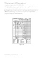
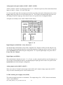
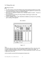
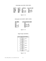
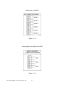
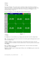
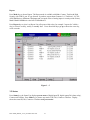
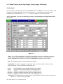
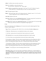
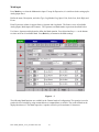
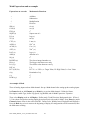
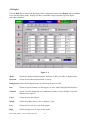
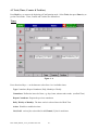
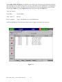
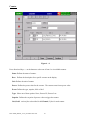
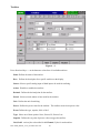
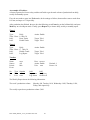
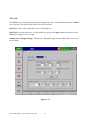
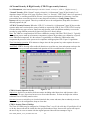
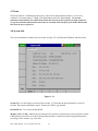
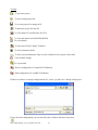
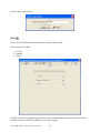
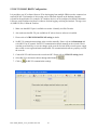
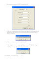
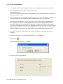
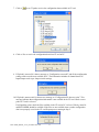
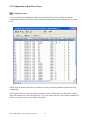
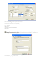
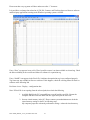
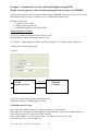
An example of Totalizer:
A factory operates for 8 hours a day, and the staff wish to get the total volume of production from daily,
weekly and monthly reports.
First, the user needs to enter into Tools mode, do the settings as follows, then totalizer starts to work from
8:30 am, and stops at 17:30 pm daily.
After production has finished, the user does the following: press Event key on the left hand side, and press
Mode key to select Report mode. Finally, press Report key to choose daily, weekly or monthly report.
Timer1
Type:
Time - Hour:
Job1:
Job2:
Daily
8 Min: 30
Reset Totalz
Enable Totalz
Action: Enable
Target: Tolz1
Target: Tolz1
Timer2
Type:
Time - Hour:
Job1:
Job2:
Daily
17 Min: 30
Disable Totalz
Log Report
Action: Enable
Target: Tolz1
Target: Tolz1
xxxx
AI1
Min
Desc: xxxxxx
Action: Enable
Unit: xxxx
Totalizer
Name:
Source:
Period:
Event
No
1
2
Type Setpoint
Hi
xxxx
Low xxxx
Job1
Log Alarm
Log Alarm
Decimal: 1
Preset: 0.0
Job2
Set DO on
Set DO off
The Weekly Report shows the following information:
The week’s production volume:
Monday: 990, Tuesday: 1010, Wednesday: 1020, Thursday: 1020,
Friday: 980 respectively.
The weekly report shows production volume 5,020.
FDC-VR06_Manual_V2.37_November-2011.doc
49
4.4 Instrument
Press Back key, to return to the beginning of Configuration mode. Select Instrument then press Enter
key to get into Instrument mode.
Figure 4 – 10
Instrument
Name: Assigns a name for the recorder in maximum 8 characters.
Language: English, Spanish, French, German, Italian, Polish, Russian, Japanese, Korean, Thai, Chinese
(simplified) and Chinese (traditional) may be selected.
Event Limit: Selects the highest possible numbers 512 or 1024 for events (including alarms).
Security: Select “Normal” or “CFR-21” security.
• “Normal” security allows different users to key in a common password.
•
The “CFR-21” offers Higher Security with CFR-21 type security.
Define each user as Supervisor or Operator with different authority to access the recorder
and different passwords.
Time limit during operation; 10 minutes since last key action requires the user to key in
password again.
Audit trail function to record the user, time and what operator actions.
Details explained in 4.6 Security & High Security with CFR-21 type security features.
FDC-VR06_Manual_V2.37_November-2011.doc
50
Data Transfer:
• Select Dump and Clear if the user wishes to clear the data on recorder after dumping data to PC
or CF card.
• Select Transfer and Remain if the user wishes to have the data remain on recorder after
transferring data to PC or CF card. This allows user to view data in the History View that has been
dumped to CF card or transferred via Ethernet with Observer II software.
Keypad Sound: Selects the following four options: disable, minimum, medium or maximum
LCD:
Screensaver: To prolong the life of the LCD display, it is suggested the display turn-off time is set to 1,
10, 20, 30, 40, 50 or 60 minutes after the recorder is operated. The recorder continues to record data
while it is in the Screensaver mode. The display turns on again by pressing any soft key. When an alarm
occurs, it turns on the display as well. The factory default setting for the Screensaver is 10 minutes.
Sensor:
Off & On: Keypad; Turn off & on by keypad. If the Screensaver is set 10 minutes, the display turns off
10 minutes after hands off from the recorder, and it turns on again after the user presses the keypad.
Off & On: IR; Turn off & on by infrared sensor. If it is the same Screensaver setting, the display turns
off 10 minutes after the user is away from the recorder and it turns on when the user approaches the
recorder within 2 meters.
Off: IR, On: Keypad; Turn off by infrared sensor, and turn on by keypad. If it is the same Screensaver
setting, the display turns off 10 minutes after the user is away from the recorder and it turns on again
after the user presses the keypad.
Note:
◆
◆
The IR (Infrared) detector works with the Screensaver; it cannot function alone. However, the
Screensaver can function alone if the IR Sensor is disabled.
The infrared IR sensor is an ingenious manner to prolong the lifetime of LCD display. It senses the
movement of body temperature when a user approaches or walks away. (distance - approx. 2 meters.)
Communication
PCTransfer: Selects RS-232/RS-485/RS-422, or standard Ethernet communication.
RS-232, RS-485, RS-422:
Address: 0 to 247 nodes for RS-485
Baud Rate: Selects it from various Baud rates 1200, 2400, 4800, 9600, 19200, 38400, 57600
or 115200.
Data Format: Selects it from three different data formats.
FDC-VR06_Manual_V2.37_November-2011.doc
51
Ethernet:
IP: Select Automation if the server on the network automatically allocates the IP address for the
recorder. Select User Define to manually set a fixed address for the recorder. Two new columns will
appear for keying in fixed addresses
IP Address: Defines the correct address of the recorder on the network
Subnet Mask: Defines the correct SubnetMask address on the network
Default Gateway: Different Gateway has different IP address on Ethernet.
Note:
▲ If Automation is selected, the IP address and SubnetMask are invisible. IP address can be found in 4.8
System Info under Configuration. Because IP address might be reallocated with new address by the
server after power off and on, the user defining fixed addresses is recommended.
FDC-VR06_Manual_V2.37_November-2011.doc
52
4.5 Clock
Press Back key, to return to the beginning of Configuration mode. Selects Clock then presses the Enter
key to get into Clock (Date/Time) mode to set up the local time.
Date Style: Selects either month/date/year or date/month/year
Date/Time: Set up the local time. Use directional keys going to the Apply column, and then press the
Enter Key to apply it to the recorder.
Summer time / Daylight Savings: Summer time / Daylight Savings may be enabled and set to occur at
specific dates.
Figure 4 – 11
FDC-VR06_Manual_V2.37_November-2011.doc
53
4.6 Normal Security & High Security (CFR-21 type security features)
In 4.4 Instrument, select from the Security Level field “Normal” security or “CFR-21”`[Higher Security”].
“Normal” Security: With “Normal” security selected in “4.4 Instrument” [page 50] the Security Level
dropdown shown in Figure 4-10 [page 50] allows “None” or “Security”. With “None” there is no password;
with “Security” a common password for all users is used; password maximum is 8 characters. Once the
password has been created the user needs to enter the password whenever Config, Dump, Clear or
Operate soft keys are required. These keys enable the user to do configuration, dump data, clear data or
manually operate the job.
“CFR-21” Security Features: When the “CFR-21” is selected in “4.4 Instrument” [page 50] the recorder
operates under more restricted rules, many of which are required by CFR-21 Part 11. The CFR-21 security
selection defines two types of users, Supervisor and Operator, each with different authority to access the
recorder by using different passwords as shown in Figure 4-12 directly below.
Note: The VR06 as a component has NOT been validated to comply with FDA CFR-21 Part 11. Typically
the complete process made up of numerous components, software & procedures are validated as a system,
not as individual components. It is the end user’s responsibility to validate the VR06 and/or other
components & processes in the system are in compliance with appropriate CFR-21 part 11 regulations.
Time limit during operation: If 10 minutes or longer since the last operator key action requires the user to
enter password again.
Audit Trail: CFR-21 Security offers audit trail function to record the user, time and operator actions to the
event list. Incorrect password and unauthorized operation will be recorded into the event list as well.
Figure 4 – 12
CFR-21 Security Operator Levels:
Supervisor: Supervisor can define all the user names including other Supervisors and Operators with a
maximum of 30 users. Supervisor has access to all recorder functions. At least one Supervisor with an
unlimited Time of Validity must be active.
Operator: Access to vertical keys to view the historical data, events and status, but no authority to access
horizontal keys to do configuration, dump or clear data.
CFR-21 Security Time of Validity:
The Time of Validity may be configured as “Unlimited Time” or as 30, 60 or 90 days. If specified as 30, 60
or 90 days the account will be closed after the specified number of days; however the system will request
the user to key in a new or remain with the original password when the user attempts to log in.
FDC-VR06_Manual_V2.37_November-2011.doc
54
4.7 Demo
The Demo mode is a simulation mode used as a sales tool for demonstration purposes. It was set to
simulate 18 AI analog inputs, 12 Math, 6 DI digital inputs and 6 DO digital outputs. To start the
automatic demonstration, first enable Demo mode, then turn the power off and on to make it effective.
To stop the automatic demonstration and return to real mode with real inputs, first disable Demo mode,
then turn the power off and on.
4.8 System Info
The system information includes System version, memory, CF card, Ethernet IP address and Slots status.
Figure 4 – 13
System Ver: It is the firmware version of the recorder. V2.20 means the present firmware version of
recorder. Plus means with Math, Counter, Totalizer & CFR-21 type features.
Boot ROM ver: It is version of Boot ROM.
Memory (Free / Total): Indicates the percentage of free memory to total memory reserved on the recorder.
8 MB memory on board is reserved for storing measured data. A small icon on the top right indicates the
percentage of free memory e.g.: mem 96%.
FDC-VR06_Manual_V2.37_November-2011.doc
55
CF Card (Free / Total): Indicates the percentage of free memory to total memory of the Compact Flash
card. e.g. CF 84%.
Ethernet IP Address: It is the present IP address of the recorder.
Slot 1 though 6: Indicates the status of all Slots and the cards been inserted in. The cards include Analog
Input AI, Digital Input DI and Digital Output DO (6 relay card).
Update: The Update key is located at left lower side. It is the key to upgrade new firmware. After the new
firmware is downloaded from a PC to the CF card insert the CF card in the VR06 CF slot. Then press this
key to upgrade it. It may take a few seconds to finish the process.
4.9 A configuration example
Here is a process required for a paperless recorder with 3-channels of 4-20mA input, 6-relay outputs and
Ethernet communication for real-time monitoring.
•
•
•
•
•
•
With, Analog input card AI183, not yet fitted into rear slot, set up 4-20mA input according to 2.3
Setup input and output cards, and then plug it into rear SLOT 1.
Plug 6-relay output card DO181 into rear SLOT 2.
Do the wiring and installation onto panel.
Set up the extensive PC software Observer II to PC, then power on the recorder.
Open the front cover at the bottom side, then 5 soft keys appear.
o Press Config key to do Configuration.
o Press Enter key to get into Channel mode. Do settings according to 4.1 Channel. Define
the names for each channel, choose Log speed 1S, Method Instant, Range 4.000~20.000,
Scale Unit %, Low 0.00 and High 100.00. Define the Event (alarm) High alarm H for
Channel 1, 2 & 3, and then define Job1 with Log alarm.
o Then, do the rest of the settings according to 4.2 Display, 4.3 Tools, 4.4 Instrument and 4.5
Clock. If the IP address of the recorder is fixed for Ethernet communication, (not
automatically assigned by the server), then the user needs to define IP as User Defined.
Then set up the IP address and Subnet Mask in 4.4 Instrument.
The recorder is now ready for real-time monitoring and data acquisition.
If the user does not need PC communication and intends to read measured data from the CF card on a PC,
then install the basic software Observer I in the PC, and add a CF card reader on USB port of PC.
To read the configuration and measured data on CF card for the first time, it is necessary to press the
Save key to save configurations first, and then press the Dump key to Dump measured data from the
recorder to CF card before inserting it into the CF card reader.
If VR06 configuration has been changed, it is necessary to press both keys before inserting the CF card
into the reader. If the configuration remains unchanged, to dump measured data press the Dump key, do
not press the Save key again. After that, the measured data can be seen in trend or Excel format on PC.
A 1GB CF card is provided as standard with higher capacity cards optional.
FDC-VR06_Manual_V2.37_November-2011.doc
56
5. PC software and Communication configuration
5.1 Observer I & Observer II PC software guide
Observer I & II software are used in conjunction with the VR06 to archive, analyze measured data from the
recorder and to do recorder configuration through PC.
This is simple guide for PC software. After completing the Set up procedure the user may view HELP
and use it as an instruction manual.
Software: These programs are Windows 98, Windows ME, Windows NT, Windows 2000, Windows XP
and Vista compatible.
Hardware requirements are shown below.
PC with Minimum 200 MHz processor, 64 MB RAM
100 MB free space in the hard disk.
RS 232 serial port/ Network adopter RJ 45 female/ USB port and CF reader
Their different applications are:
VR06 without communication:
Observer I: Basic software is supplied with each recorder to view
measured data and VR06 configuration read via CF card.
VR06 with communication:
Observer II: Extensive software is an optional software package
with the same features as Observer I and in addition allowing:
• Communicate over Ethernet or optional RS/232/422/485
Modbus
• Import Real Time Data from VR06 over Modbus or Ethernet
Observer I contains two components
Configuration: The user may receive configuration from the recorder via CF card, change recorder
configuration on PC and send modified configuration back to the recorder via CF card.
Historical Viewer: Receives and views historical data stored by the recorder and Dumped to the CF card,
FDC-VR06_Manual_V2.37_November-2011.doc
57
Observer II contains three components
The Configuration and Historical Viewer are the same as described in Observer I. However Observer II
allows data dump via CF card as with Observer I OR via Observer II with Ethernet or RS232/422/485.
Real-time Viewer: Receives and views real-time data measured by the recorder. When setting up a new
project in Real-time Viewer, click the icon “ Configuration data, and do the configuration for real-time
viewing on the PC.
When the recorder is communicating with a PC via Ethernet or RS-232/422/485, Observer II is able to
monitor real-time measured data “ Received" from the recorder. The real-time measured data can be
viewed in different formats: digital, trend, bar plus Event/Alarm list can be displayed in individually or in
groups.
While running Real-Time Viewer the Trend view can be configured for various time periods. Changing
trend view time periods is easy and all data since Observer II began communicating with recorder is
available – dependent upon PC memory.
Note:
Ethernet is the standard communication with this instrument. To enable Ethernet functions, it is required
to order the extensive software Observer II.
◆
The configuration of Real-time Viewer is set in the PC. This is different from the configuration of
Historical Viewer, which is the same as the recorder [trend view time setup].
◆
With Observer II it is required to key in IP address of recorder. This IP address can be found in 4.8
System Info mode under Configuration.
Install Observer Software
Run the setup exe available on CD supplied and follow on screen instructions. At any point in time only
one version of Observer, either I or II may exist in a PC. If user install new version of observer software,
old version will be deleted automatically during installation of software.
Uninstall Observer Software
This is to remove Observer software from PC. Observer I or Observer II may be uninstalled from PC any
time from the following two ways
Control panel- Add/remove programs-observer I/observer II
Start –Programs-Observer I / Observer II / Uninstall
FDC-VR06_Manual_V2.37_November-2011.doc
58
Tool bar
To open new project
To open existing project file
To save the project file settings in PC
To delete the project file from PC
To select bank (CF card/ Ethernet / RS 232)
To select the channel (AI/AO/DI/DO/MATH)
To select display
To select tools (Timer/Counter/ Totalizer)
To select instrument details
To select system information (Type of cards available at slots, system version info)
Clock summer settings
To set password
Receive configuration (CF reader/RS 232/Ethernet)
Send configuration (CF card/RS 232/Ethernet)
If Observer software is already configured in the PC, select *.prj file to see a listing of all projects.
For the first time configuration you can cancel the above window and select new project
FDC-VR06_Manual_V2.37_November-2011.doc
59
Enter the name of the project.
Bank
This is used to select physical connection between the recorder and PC.
Three options are available
1. CF card
2. Ethernet
3. RS 232
1GB CF card shall be supplied along with the recorder. Standard Ethernet port (RJ 45 female) shall be
available at the recorder. RS 232/ RS485 is offered as an option.
FDC-VR06_Manual_V2.37_November-2011.doc
60
5.2 Ethernet Configuration (Observer II)
It is possible to use PC software Observer II for data logging from multiple units of recorders connected
on standard Ethernet. Total number of devices that can be connected depends on the hardware interface
selected for the application. For example, 255 hardware devices can be connected on Ethernet. Maximum
1024 tags can be configured at Observer II for data logging, archiving and analysis. The tags cover AI,
Math, DI, DO, Counter & Totalizer.
1. Make sure that network adapter in PC is properly configured. IP address, Subnet mask and
Gateway should be configured at the PC for using Observer II program. Please contact System
administrator to set Unique IP address for the PC.
2. Install Observer II application software in PC. The software may be installed from setup available
in the CD supplied as per the order.
3. Ethernet configuration at Recorder
Please refer to 4.4 Instrument entering IP address, subnet mask and gateway address manually at
the recorder.
Gateway refers to a device on a network that sends local area traffic to other networks.
Subnet mask numbers help to define the relationship between host and rest of the network.
For every LAN, the Network administrator shall define Subnet mask and Gateway. Obtain subnet
mask and gateway address for the LAN at the place where the recorder to be connected. Enter
these details at the Recorder manually using front buttons.
By default, subnet mask address: 255.255.255.0
By default, Gate way: 0.0.0.0
Allocate the Unique IP address to the recorder and enter IP address at the recorder manually.
Contact System administrator for obtaining free IP address available at user LAN. Naming
duplicate IP address may disable the communication between the recorder and PC/LAN HUB.
4. Local area network uses UTP cable for Ethernet connectivity. Maximum UTP cable distance
between the recorder and LAN/HUB/PC should be less than 100 Meters. If the distance is more
than 100 Meters, additional LAN accessories/equipments may be required for increasing signal
strength. Please contact network administrator for more information on extending LAN.
5. Two different types of cables shall be used for connecting the recorder on Ethernet as follows.
For connecting the recorder to LAN HUB, then standard straight-through Ethernet cable
should be used.
For connecting the recorder to PC/Notebook directly, then a crossover Ethernet cable must be
used.
FDC-VR06_Manual_V2.37_November-2011.doc
61
Straight Through
Cable
VR06-LAN/HUB
Crossover
Cable
VR06-PC/Notebook
RJ-45
PIN
RJ-45
PIN
RJ-45
PIN
RJ-45
PIN
1 Tx+
1 Rc+
1 Rx+
3 Tx+
2 Tx-
2 Rc-
2 Rc-
6 Tx-
3 Rc+
3 Tx+
3 Tx+
1 Rc+
6 Rc-
6 Tx-
6 Tx-
2 Rc-
6. Connect proper UTP Ethernet cable as per the requirements and observe the communication status
between the Recorder and PC/LAN HUB at the LED’s dedicated for the purpose near female RJ
45 connectors.
Recorder side
Link (Green LED)
Green lit: Cable connected between the recorder and PC/LAN HUB
Green Off: No Link between the recorder and PC/LAN HUB
Tx/Rx
Orange Lit continuous: No cable connection
Orange slow blink: Communication established between recorder & PC/LAN HUB
7. If the communication between the recorder and PC/LAN HUB is successful, then start Observer II
in the PC as follows
Start-Programs-Observer II – Configuration
For the first time, Under Historical folder .prj file shall not be available.
Open new file
Enter new name for the project, i.e. “Boiler”
FDC-VR06_Manual_V2.37_November-2011.doc
62
Select Ethernet in the Bank by using radial button
Open for Ethernet connection
Enter the IP address of the Recorder
System will ask “Do you want to receive configuration data now? (Y/N)”
Click on “Yes” to upload the recorder configurations to PC.
FDC-VR06_Manual_V2.37_November-2011.doc
63
If Upload is successful, it shows message as “Configuration successful” and all the configuration
settings of the recorder are now available at PC. The information includes all channel details of
Input/Output cards as per Jumper/switch settings on the modules.
If Upload is unsuccessful, it shown message as “No response from Recorder, connection fails”.
If this is the case, please check the Ethernet cable connections at both the recorder and PC/LAN
HUB side. Also make sure that green communication LED available for proper firm connection at
RJ 45 connector.
If communication cannot be established between the recorder & PC;
Check again Subnet mask and gateway address at the recorder & PC.
Contact Network/ System administrator for proper Ethernet configuration of the recorder
& PC.
Please note that recorder should have unique IP address in the network and PC being used
for Observer II shall have separated Unique IP address in the network.
FDC-VR06_Manual_V2.37_November-2011.doc
64
5.3 RS 232, RS485, RS422 Configuration
It is possible to use PC software Observer II for data logging from multiple VR06 recorders connected on
network RS 485. Total number of devices that can be connected depends on the hardware interface
selected for the application. For example, 247 hardware devices can be configured on RS 485. Maximum
1024 tags can be configured at Observer software for data logging, archiving and analysis. The tags cover
AI, Math, DI, DO, Counter & Totalizer.
1. Make sure that RS 232 port is available at recorder. Normally it will be D9 male.
2. Also make sure that RS 232 port available at PC where observer software is installed.
3. Please refer to 2.5 RS 232/RS 485/ RS 422 wiring in details.
4. Set RS 232 communication settings at the recorder manually. Please refer to 4.4 Instrument and
select RS 232 at PC transfer. Set RS 232 communication details manually at the recorder. Please
note that press Back Key to save the changes at the recorder. Switch off the recorder power supply,
then switch on once again and make sure that RS 232 communication details are properly saved in
the recorder.
5. Connect RS 232 cable between the recorder and PC. Please refer to 2.5 RS-232 wiring details.
6. Select RS 232 in the bank as below through radial button
7. Click on
for RS 232 communication settings.
FDC-VR06_Manual_V2.37_November-2011.doc
65
8. Set communication parameters for RS 232 communication at PC.
9. Click on OK after setting all above details. By default Node address is 1. If any change is there for
the node address, then it should be set at recorder manually then enter the same node address in
the above configuration.
10. Click on “Yes” to upload the recorder configurations to PC.
11. If Upload is successful, it shows message as “Configuration successful” and all the configuration
settings of VR06 recorder now available at PC. The information includes all channel details of
Input/Output cards as per Jumper/switch settings on each module.
FDC-VR06_Manual_V2.37_November-2011.doc
66
If Upload is not success, it shown message as “No response from Recorder, connection fails”.
If this is the case, please check the RS 232 cable connections at both the recorder and PC. Also
make sure that green communication LED available for proper firm connection at back RS 232
port available at recorder backside.
If still communication is not established between the recorder & PC, then once again check Node
address at the recorder. If more than one recorder is connected in RS 485/ RS 422 network, make
sure that all the devices have unique address. Check the communication settings at the individual
recorders manually.
If the converter SNA 10A is used for converting RS 485/ RS 422 to RS 232, then make sure that
Dipswitches are correctly set for the communication details.
If RS 485/ RS 422 is used for connecting recorders, then make sure that last node is less than 1000
meters from the PC. Also make sure that STP cable is being used for RS 485 connections.
In some computers, COM 1 and COM 2 have been used for other devices. So it is required to
carefully check whether RS 232 cable is connected to proper communication port of PC or not.
FDC-VR06_Manual_V2.37_November-2011.doc
67
It is important to check COM port of PC to see whether it been properly set.
My computer-Properties-Hardware-Device Manager – Ports – COM 1 – Properties
Devise usage: It should be enabled
Device status: The device is working properly.
If above conditions are not met, then RS 232 port is having problem at PC. Contact system
administrator for replacing the port or updating driver properly.
If communication is still not established, user can try setting up Observer software in another PC
where the COM port is performing properly.
FDC-VR06_Manual_V2.37_November-2011.doc
68
Make sure that RS 232 communication setting at the recorder and PC are set with the same values.
FDC-VR06_Manual_V2.37_November-2011.doc
69
5.4 CF card Configuration
1. As standard a 1GB CF card is supplied with the recorder; higher capacity cards are available.
2. Save configurations from recorder to CF card at Recorder.
Configuration – Save.
This step will make sure that all IO cards information as per jumper and Dipswitch selection will
be saved in to the CF card.
3. Use CF reader to read the recorder configuration on CF card in Observer software. CF readers are
typically available for use at USB port and are available from a variety of retail stores.
Please note that all standard CF readers from major vendors will be detected automatically as
mass storage devices by the Win XP operating system. If you are using any other operating
system like Windows 98, windows ME, Windows NT and Windows 2000, then mass storage
device may not be detected and you have to install the driver for the CF reader. Driver CD shall be
shipped along with Observer software for configuration of CF card at PC. Please note that, you
need to configure CF card driver only if operating system not detecting mass storage device.
4. Once the PC detects CF reader along with CF card it will appear as removable drive at the
computer.
5. Start Observer program, Ex: Start-Programs-Observer 1 - Configuration
Open new file
Enter new name for the project, i.e. “Boiler”
6. Select CF card using radial button
FDC-VR06_Manual_V2.37_November-2011.doc
70
7. Click on
to set CF path to receive the configuration data available in CF card.
8. Click on Yes to receive the configuration data from CF card to PC.
9. If Upload is successful, it shows message as “Configuration successful” and all the configuration
settings of the recorder now available at PC. The information includes all channel details of
Input/Output cards as per Jumper/switch settings.
10. If Upload is unsuccessful, it shown error message as “Configuration file does not exist”. This
message indicates that configuration information is not available in the CF card. Check correct
path of CF card is selected.
If still problem exists, check the files available in the CF card at PC. At least 2 files by name IO
and RECORDER should be available. If the files are not available, then recorder configuration
data is not properly saved in the CF card. Repeat process starting at Step 2.
FDC-VR06_Manual_V2.37_November-2011.doc
71
5.5 Configuration in Real-Time Viewer
Configuration data
It is used to define the configuration of the recorder for Real-Time Viewer. Please note that the
configuration of Real-Time Viewer can be redefined and independent to the configuration of recorder
itself.
Double click on channel in the above spreadsheet to show the following Modify tag data with email
configuration.
If auto-update option is selected in modify tag data as shown in following screen, then all the settings
done at the channel for events will appear here. If it is not selected, then user can configure manually for
different set points in order to generating alarm emails.
FDC-VR06_Manual_V2.37_November-2011.doc
72
Select Send email option for the job as shown above.
The Email on event will be received like this,
Type: HiAlarm
Source: AI1
ActiveTime: 12/12/20059:49:59AM
Value: 23.8
Option: Three options of Share, Email and Communication are to be defined. It is mainly to set
email configuration and real time log speed.
FDC-VR06_Manual_V2.37_November-2011.doc
73
Share: Share/do not share options are available for user selection. If share option is selected, then
Observer data available in the computer can be shared from other computers. On selection of the share
data, shared folder will be created in C:\Observer.
For example, you have one recorder and wish to analyze historical data at different computer. While
opening project in the second computer, directly link to the project file available under C:\Observer
through network configuration. This will minimize the data transfer between recorder and the computers
and make it more efficient by using available resources through network configurations.
Email: The default Port number 25 is used to send email from STMP server. If your network
administrator configured different port in your LAN for accessing internet/email, then you have to modify
the port number accordingly.
To send an email for any event, the procedure is as follows.
Set SMTP server details as below. Please contact system or network administrator for the server details if
your computer is connected in LAN.
Host, Port, User name, From: Sender email address
To: Receiver email address (Max.10 email addresses can be selected)
Communication: It is used to set data display time for Real-Time Viewer. User can select one from the
following for real time monitoring.
For example, if recorder and Observer are located at different locations connected through Ethernet across
different gateways, this option is used to set the communication time. When 60 S is selected Observer
will exchange data with the recorder every 60 seconds. When recorder and Observer are separated in far
distance, it is preferable to use Ethernet option so that it can have better data transfer rate for
communication.
FDC-VR06_Manual_V2.37_November-2011.doc
74
Bank: It is to modify the channel for communication between Recorder and Observer from RealTime Viewer.
Four banks are available. In each bank protocol options Disable, Modbus_RS232 and Modbus TCP are
available for user selection. This Bank is used for Real-Time Viewer only, which is different from the
Bank used for recorder itself on Page 60.
For Ethernet, Recorder uses port no. 502 to communicate with Observer.
If you change the port number in Observer you cannot establish communication between Observer and
Recorder.
Port no: 502 is used to establish communication between recorder and Observer software to exchange
data on Ethernet over Modbus TCP protocol.
FDC-VR06_Manual_V2.37_November-2011.doc
75
5.6 DDE dynamic data exchange
DDE link
Dynamic Data Exchange (DDE) is a standard inter-application communication protocol built into
Microsoft Windows operating systems and supported by many applications that run under Windows.
DDE takes data from one application and gives it to another application. It allows Windows programs that
support DDE to exchange data between themselves.
Data from the Observer II software can be exchanged with Excel on DDE link.
Please note that it is not possible to exchange data directly from the recorder to third party
applications like Excel. Third party applications running under Windows and set to communicate with
DDE link can receive data through the DDE link if so configured. After review DDE issues below refer to
page 75 “DDE with third party applications”.
Once Observer II software is installed with real timer viewer and configured properly in PC, then it is
possible to exchange data between Observer software and Excel using DDE link.
Open real time viewer from start – programs – Observer II – Real-time viewer
Project – create DDE link in excel
Specify the path and file name as follows.
FDC-VR06_Manual_V2.37_November-2011.doc
76
By default the file name will start with DDE and the project name with underscore in between to avoid
confusion in naming the file. Save the file name in PC at selected path as above to proceed further. For
example, if desktop is selected in the path, then the file should be available in the desktop. Please check
up the desk top for the excel file.
If the MS Office is not installed in the PC, then you cannot open the excel file created as described above.
Please contact your system administrator to install MS office software in the PC.
Now try to open the file from the desktop created for using DDE application with the recorder through
Observer software.
Click on update to activate DDE between Observer software and Excel application. If the DDE is
successful, then real time data of the pens should be updated in excel file as shown in sample screen.
DDE expression format to get real time data from the Observer software is as follows.
=RealTime_Viewer|TagService!_AI1
Application = RealTime_Viewer
Topic = TagService
Tag name = AI1
FDC-VR06_Manual_V2.37_November-2011.doc
77
Please note that every tag name will have underscore after “!” character.
It is possible to exchange data related to AI, DI, DO, Counters and Totalizers between Observer software
and third party applications running under Windows operating systems via DDE.
If any “Error” test appears in any cell of Excel, possible reasons is no data available at selected tag. Check
the data availability at the recorder and Observer software for a particular tag.
If any “NAME” text appears in the Excel file, it indicates that particular tag is not configured properly.
Tag name may not available in Observer software. If this happens, check the valid tag names in Observer
software at the following link
Real time viewer - Display – configuration data
Note: If Excel file is not opening from the selected path, then check the following
1. Available RAM in the PC is not sufficient to run & load the excel file. Restart the
computer and then create the DDE link once again and open the Excel file.
2. Increase virtual memory in the PC. Please contact system administrator to check the
virtual memory settings in the PC in following steps.
My computer-properties-advanced-performance settings –advanced-virtual memory.
FDC-VR06_Manual_V2.37_November-2011.doc
78
DDE with third party applications
Once the data is available at Excel at particular cell, then data can be exchanged with the third party
applications like PLC, SCADA, and Visual Basic etc.
If data is to be exchanged with PLC, then PLC programmer can write Visual basic macro in Excel from
the following link
Excel – Tools – macro
For the source code examples, PLC programmer may check the PLC manuals for DDE sample macros.
It is also possible to exchange data from recorder to SCADA applications through DDE.
Example 1
DDE link between Allen-Bradley SLC 5/03 PLC and Excel
Task: Write a block of data (10 floating points) from Excel to PLC.
Name of the Excel file = Reports.XLS
Data Source: D 37 to D 46, data in total 10 cells
Target= PLC, Starting address= F8
User RSLinx to configure PLC and DDE link
DDE topic name in RSLinx= DDE_REPORTS
Sub Block_Write()
'open dde link: testsol=DDE Topic This is comment only
RSIchan = DDEInitiate ("RSLinx", "DDE_REPORTS")
'write data thru channel This is comment only
DDEPoke RSIchan, "F8:2,L10", Range ("[Reports.XLS]PROCESS!D37:D46")
'close dde link This is comment only
DDETerminate (RSIchan)
End Sub
FDC-VR06_Manual_V2.37_November-2011.doc
79
Example 2
DDE link between Allen-Bradley SLC 5/03 PLC and Excel
Task: Read a block of data (5 integers) from PLC to Excel
Name of the Excel file = Reports.XLS
Data Source: PLC, Starting address= N7:30
Target cells in Excel= A7 to A11
User RSLinx to configure PLC and DDE link
DDE topic name in RSLinx= DDE_REPORTS
Sub Block_Read()
'open dde link: testsol=DDE Topic This is comment only
RSIchan = DDEInitiate("RSLinx", "DDE_REPORTS")
'get data and store in data variable. This is comment only
data = DDERequest(RSIchan, "N7:30,L5,C1")
'Paste data into selected range. This is comment only
Range("[Reports.XLS]DDE_Sheet!A7:A11").Value = data
'close dde link. This is comment only
DDETerminate (RSIchan)
End Sub
FDC-VR06_Manual_V2.37_November-2011.doc
80
Example 3
DDE between Observer software and SCADA (Allen-Bradley RSVIEW32)
When the Real time viewer in Observer II is working well in PC, then the tag data from Observer
software will be available in the expression format as follows
=RealTime_Viewer|TagService!_AI1
Application = RealTime_Viewer
Topic = TagService
Tag name = _AI1 (Please observe underscore before the name of the tag)
The above tag information can be directly configured in SCADA to enable DDE between Observer
software and RSVIEW 32 SCADA. There is no need to configure any thing at RSLinx.
Procedure for configuration
1) Open SCADA project
2) System – Node – Select DDE server as data source
3) Name = VR06 (No gaps)
4) Application = RealTime_Viewer
5) Topic = TagService
6) Check enable in the box. (This node should be selected)
7) Now open the data base
8) Create analog tag with all the details similar to the tag at the recorder.
9) Select VR06 at the NODE
10) Write the tag address, this should be same as tag name at the recorder and Observer software.
For ex: analog input 1 as AI1 should be written as _AI1 (Please note that underscore is
required before the name of the tag, otherwise data will be not exchanged.
11) Now open the tag monitor and configure for the above tag for checking of DDE with the tag.
If DDE is configured properly, then tag value should appear correctly at the tag monitor with state as
“VALID”. If any error message is available, then you have to repeat from step 1. Please note that before
checking tag monitor, real time viewer in PC should be in running condition.
FDC-VR06_Manual_V2.37_November-2011.doc
81
6. Application examples
Example 1: Flow measurement
A level has to be converted into a flow according to the following formula.
Q (calculated flow speed in liter per minute) = 0.0072*h *60
h (level range in mbar per second) = 0 – 30 mbar
In 4.1 Channel Mode of Configuration, set AI1 as follows,
Name: Level 1
Desc: xxxxxx
Method: Instant
Speed: 1 S (1 second / data)
Offset: 0.00
Gain: 1.000
Sensor: Current
Unit: mA
Range: 4.0 ~ 20.0
Scale
Unit: mbar
Low: 0.00
High: 30.00
Press Math to get into Math Channel and set Math1 as follows,
Name: Flow 1
Desc: xxxxxx
Type: Enable
Log Method: Instant
Speed: 1 S
Expression: 0.0072*AI1^2.5*60
Unit: l/min
Low: 0.0
High: 2200.0
Example 2: 8:00 am start logging, 17:00 pm stop logging Monday-Friday
Select Tools mode of Configuration, and define Timer 1 – 4 as follows,
Timer 1
Type: Daily
Timer 2
Action: Enable
Type: Daily
Time: 8 Hour 0 Min.
Time: 17 Hour 0 Min.
Job 1: Start logging
Job 1: Stop logging
Timer 3
Timer 4
Action: Enable
Type: Weekly
Action: Enable
Type: Weekly
Action: Enable
Time: Saturday
8 Hour 1 Min
Time: Sunday
8 Hour 1 Min
Job1: Stop logging
Job1: Stop logging
FDC-VR06_Manual_V2.37_November-2011.doc
82
Example 3: Communicate recorder with mobile phone through SMS
Mobile receiving process value and alarm messages from recorder via GSM8000
By using analog output card AO 183I and GSM controller GSM8000, remote retrieval of process values
and alarms from the recorder to a cellular device via SMS through GSM system.
Hardware requirements
1. Paperless recorder VR06
2. Analog output card AO 183I
3. GSM 8000 controller (8 AI, 8 DI & 8 DO)
Set up at paperless recorder
Ex: RTD is connected at channel 1 in the recorder. (AI1)
Retransmission is required for Analog input1 say AI1
Use AO183I – Analog output card for Re transmission purpose. It is 3 channel analog output card.
Configuration of Analog output card
Channel 1:
______________________________4-20 mA____
+
AO 183I
+
Paperless Recorder
_________________________________________
-
GSM 8000
Controller
AO 183I: 3-channel analog output retransmission card
GSM 8000 controller: 8 Analog inputs, 4-20 mA
GSM 8000 controller set up
Insert SIM card in GSM controller, set up the controller as per user manual
Enter Supervisor and Operator mobile numbers in GSM controller. These are the mobile numbers to
which SMS message to be sent from the GSM controller.
Select channel number1, set low scale for 4 mA = 0, set High scale for 20 mA = 100
Set Alarm levels, Low = 40 and High = 80
FDC-VR06_Manual_V2.37_November-2011.doc
83
To know the process values in your Mobile
Send SMS from mobile to GSM controller as follows
GET-CH
This is to send SMS command from mobile to GSM controller to get analog inputs real time
value. If the SMS command is properly framed and sent to GSM controller, then mobile will get
the following confirmation from controller.
CHS = HHLHLLLL
C1 = 60.2 oC
C2 = 245.2 ACV
C3 = 980.5 WATT
C4 = 8.634 pH
C5 = 200.5 uS
C6 = 99.52 ACA
C7 = 502.4 Lux
C8 = 75.91 dB
Channel H/L/N status
H = Reading on High value
L = Reading on Low value
N = Reading on Normal value
CH1 reading value with unit
CH2 reading value with unit
CH3 reading value with unit
CH4 reading value with unit
CH5 reading value with unit
CH6 reading value with unit
CH7 reading value with unit
CH8 reading value with unit
Alarm: Any time the alarm set on GSM controller is activated, SMS will be generated automatically
from GSM controller and sent to preconfigured cellular device in similar format as above.
FDC-VR06_Manual_V2.37_November-2011.doc
84
7. Trouble shooting
FDC-VR06_Manual_V2.37_November-2011.doc
85
FDC-VR06_Manual_V2.37_November-2011.doc
86
FDC-VR06_Manual_V2.37_November-2011.doc
87
8. FAQs frequently asked questions
Q1: What is the maximum scale low and scale high values we can set in the recorder for the analog
inputs and outputs?
A1:
The minimum low scales of analog input are various -19999, - 1999.9, - 199.99, - 19.999, -1.9999,
-0.19999 depending on the position of the decimal point
The maximum high scales of analog input are various 45536, 4553.6, 455.36, 45.536, 4.5536, and
0.45536 depending on the position of the decimal point
The minimum low scales of Math input are various -32768, -3276.8, -327.68, -32.768, -3.2768,
-0.32768 depending on the position of the decimal point
The maximum high scales of Math input are various 32767, 3276.7, 327.67, 32.767, 3.2767, and
0.32767 depending on the position of the decimal point
Q2: What is the maximum distance between PC and Recorder for Ethernet communication?
A2:
The distance is limited in 100 meters. If it is farer than that, then you can use Hub or networking
bridge to strengthen the signal.
Q3: What is the maximum distance if PC is accessing data from recorder on wireless network
through Ethernet protocol?
A3:
Maximum distance should be within 30 meters. Also make sure that there are no obstacles/ HT
cables between PC and recorder to avoid communication errors. Also Noise could effect the
wireless communication at the factory floor.
Q4: Is there any battery available inside the recorder, which needs to be changed frequently?
A4:
The lithium battery Toshiba CR2032 3.0V/220mAH can last for many years. It can be replaced by
local sourcing if Real Time Clock is not working properly.
Q5: What is the accuracy of Real Time Clock in the recorder?
A5:
The crystal oscillator used in recorder could have a lag time in a few seconds each week. Press
Synchronization button in PC software Observer II to synchronize the time between PC and the
recorder. The temperature inside the housing has an effect on accuracy of Real Time Clock of
crystal oscillator.
Temperature range
Time lag per month
10 ~ 40 ˚C
0 or 50 ˚C
-10 or 60 ˚C
18 seconds
52 seconds
107 seconds
FDC-VR06_Manual_V2.37_November-2011.doc
88
Q6: What kind of security is available in recorder?
A6:
There are two kinds of security.
1. Normal security offers a common password.
2. High security with CFR-21 Part 11 type features is available from version 2.2 and later
versions on both recorder and PC software Observer. It supports maximum 30 users with
different passwords. The Supervisor has the right to define other supervisors and operators.
The supervisor can change configuration, save and clear data but not operators. Operators can
only view the historical data, events and status.
Q7: What is Boot Rom? Anything related to Math option? Is it possible to upgrade it into new
version via internet or CF card?
A7:
Boot ROM is a chip installed in the recorder containing system boot information. The Boot ROM
BT182 is supplied with Math, Counter, Totalizer & CFR-21 part 11 type features. It is not
possible to upgrade the Boot ROM via Internet or CF card.
Q8: How are the VR06 recorder firmware & PC Observer software upgraded to latest version?
A8:
If necessary, contact your supplier about the latest updates or visit our website
http://www.futuredesigncontrols.com. Your supplier is able to supply the latest version of
recorder firmware system and PC software on CD or via email or FTP (file transfer protocol).
Follow the procedure to update the recorder firmware. Install the new version of Observer
software; it will automatically uninstall the old one.
Q9: Are there other considerations prior to updating recorder firmware to most recent version?
A9:
Any recorder firmware before V1.20 must first be updated to V1.20. Direct update to the latest
version could damage the DOC. Once recorder has V1.20 it may be updated to the most current
firmware. Note V1.20 began shipping approx. January 2004.
Q10: What are the differences between Observer I & Observer II PC software?
A10: Observer I is supplied as standard & Observer II is supplied at additional cost.
Observer I is used for recorder configuration from PC and reading historical data in PC at set time
period of 1 to 24 hours. Data is exchanged between recorder & PC via CF card. Observer II is
used for real time data monitoring in PC via Ethernet or RS232/422/485 along with configuration
and historical data view.
Q11: How many AI, AO, DI, DO cards, and 24VDC auxiliary power card can be inserted into the
recorder?
A11: Maximum 6 cards in any combination can be inserted into rear Slots.
Q12: What are those larger capacities of compact flash cards supported by the recorder and
FDC-VR06_Manual_V2.37_November-2011.doc
89
recommended manufacturer?
A12: If the user prefers to use larger capacities CF card we usually recommend 2GB. To be fully
compatible, we only recommend one brand SanDisk CF card.
Q13: What is the product warranty period of time? How does the user handle the defective
recorder?
A13: Warranty period is 24 months from ship date. Contact your supplier or Future Design Controls
directly.
Q14: What is the procedure to transfer data from the internal memory to CF card after the
internal memory is full?
A14: After 8MB internal memory is full, the earliest data and events will be saved into CF card in small
batch automatically, details in 3.11 Small icons.
Q15: Is Alarm banner available in the recorder along with customized message display?
A15:
Alarm banner is unavailable for customized message display. The alarm banner appears after
alarms or events occurred, or the internal memory or CF card is running shortage. A buzzer can be
set to activate if any alarms/events arise.
Q16: How many analog and math channels available and is it possible to retransmit these channels?
A16: Maximum 6 analog inputs plus 18-math inputs are available in one recorder. It is possible to
retransmit the analog and math channels by using 3-channel current output card AO183I or 3channel voltage output card AO183V.
Q17 Is the recorder supplied with OPC server?
A17: The OPC server is not available in the VR06 but will be in the next generation VR20 scheduled
for release late 2007. However Observer II PC software does offer DDE solution to allow data
transferred to other devices like PLC, SCADA etc. Please review a few examples in 5.5 DDE
dynamic data exchange.
Q18: Which protocols and hardware interface recorder supports?
A18: The protocol for RS-232, RS-422, RS-485 communication is Modbus RTU. For Ethernet
communication, the protocol is TCP/IP.
Q19: How many recorders can be connected in a network?
FDC-VR06_Manual_V2.37_November-2011.doc
90
A19: It depends on hardware interface selected. With Ethernet communication a maximum, 255 devices
can be connected in the network with each device requiring a unique IP address. With RS 485
communication a maximum of 247 units can be connected in the network.
Q20: How many recorders can be viewed in the Real-time Viewer of PC software Observer II?
A20: Maximum 1024 tags can be viewed from the Real-time Viewer. These tags cover AI, Math, DI,
DO, Counter and Totalizer, excluding AO. As an example if on average each recorder has 6 tags
read, then the Real-time Viewer can view maximum of 170 recorders.
Q21: Once the user forgot the password, is there a common password? If not, how to reset
recorder to the factory settings?
A21: There is no common “back door” or hidden password. If the password is lost the recorder must
be reset to factory default settings using the RESET procedure. Press and hold the top left key
with power off and turn on the power. Do not release it until you hear two "BI " sounds. Turn the
power off and on again. All factory settings will be restored. Please note that after this procedure
all project configuration data have been erased; the recorder will have to be re-configured.
Q22: To change the analog input using Observer I or II software, what is the next step after
changing the dip switches and jumpers on the analog input card?
A22: Observer II connected to recorder via Ethernet or RS232/422/485; press the icon to receive
configuration from the recorder to PC.
Observer I or II via CF card; first save new configuration on recorder since changing DIP-switch
settings on input card to CF card. Then open configuration file from within Observer.
Modify the configuration as necessary and send the new configuration back to the recorder in the
same fashion as it was read.
Q23: Which type of Ethernet cable should be used to connect with the recorder?
A23: Straight through cable should be used for the real network connection between HUB and recorder.
Cross-through [patch cable] cable should be used for the non-real network connection such as
between PC and recorder.
Q24: How many days the data can be stored in CF card?
A24: It depends on the number of channels, the log speed of channels, and the memory size of CF card.
If the recorder is used with 6-channel inputs, an easy chart to show the maximum days CF can
store the data.
CF card memory size:
Log speed
1 second
10 seconds
120 seconds
FDC-VR06_Manual_V2.37_November-2011.doc
1GB
980 days
9,870 days
118,510 days
91
Q25: Is it possible to display all the selected channels in one page on recorder?
A25: Yes, press Page key to get to Page all mode. Then, all selected channels in digits can be displayed
in one page.
Q26: Is it possible to print out the data in selected time from the recorder?
A26: No, it is not possible to connect printer directly to the recorder. However it is possible to print out
the data in selected times from the Observer software. Observer also supports exporting Historical
& Event files in .csv format which when opened in Excel can be sorted and printed.
If any error appears when user attempts to print data, i.e. floating point error, the reason might be
that data is not available for selected pens. Search by a specific time or by a period of time making
sure that data is shown on the trend line. Select the pen correctly and proceed with the printing.
Q27: How many timers, counters and totalizers are available in a recorder?
A27: 6 counters, 6 timers and 18 totalizers are available in one recorder.
Q28: Can I use digital inputs for the counting application?
A28: The sample rate of recorder is 200 msec and the quickest data log speed is 1 sec per data. It is
possible to use digital input(s) as counter(s) if the duration between two pulses is more than 200
msec. Recorder will not detect pulses if the duration is less than 200 msec. Recorder can detect
maximum 5 counts/sec or 300 counts/min or 18000 counts/hr. For applications pulse duration
faster than 200 msec a third party converter is required (pulse to 4-20mA converter).
Q29: When Observer II software, the user may see the following message, what is the next move?
A29: Most likely the Observer software file was corrupted in the PC; possible reasons might be a virus
or installation of new incompatible software with your operating system. The solution is to
uninstall the old Observer software as per procedure given in section 1.4 of this software guide.
Then, install the new Observer software from CD supplied. If the problem still can’t be solved,
then uninstall the old Observer software and create a back up for the historical and real-time
folders under C:/Observer and remove Observer folder from C: Then install the new Observer
software again.
FDC-VR06_Manual_V2.37_November-2011.doc
92
Q30: How to write Observer data and configurations back up to CD’s?
A30: Data will be available at .dat,idx files and .lst files at the path C:/Observer. The files will be
available under historical and real-time folders. Configuration file name is Recorder.config. You
can create a folder and save all historical and real time folders in to back up folder and then you
can write this information to CD.
Q31: If I have some configuration problems, which files I have that to send to the supplier?
A31: Both Recorder.cfg and IO.dat files found in C:/Observer/Historical are required.
Q32: Does the recorder have an option to supply DC power supply to the transmitters?
A32: The AP181 transmitter module has 6 non-isolated 24VDC power supply terminals with a
maximum of 30mA per channel. This power supply is electrically isolated from other I/O of the
recorder and is installed in one of the six module slots on the back of the recorder.
Q33: I am trying to connect recorder on RS 232/RS422/RS485/Ethernet but I couldn’t set up the
communication properly.
A33: Please refer detailed information to 5.1 Observer I & Observer II PC software guide, 5.2
Ethernet Configuration & 5.3 RS 232, RS485, RS422 Configuration.
Q34: When export data as .csv format to read in Excel what if the historical data is not appearing
in spread sheet?
A34:
Make sure that the selected pens are available at destination list. If they are available at source list,
then move them to destination list, and then you can export data. Also make sure that data is
available at the selected period or interval time, otherwise you may not see anything in the target
Excel sheet.
FDC-VR06_Manual_V2.37_November-2011.doc
93
Q35: I want to count pulses to measure power consumption in KWH. Each pulse is one KWH.
Can I use Math application for this?
A35: Yes, use DI and configure Events of Channel as follows
Event Type = High, Job 1 = Increase Counter, Target = Counter 1
But please note that maximum value counter can store is 65535.
Note that if you have time period between pulses less than 200 msec, then you cannot use digital
input at the recorder. A possible solution is to use an external converter for the application. The
standard pulses to 4-20mA converters are available in the market where you can set pulse width
and duration between pulses (frequency).
Q36: I am getting the following message in Real time viewer. What to do next?
A36: The firmware V2.21 or earlier version does not allow the user to key in special characters like “.”
“,” “*” “+” “-” etc. in Tag name. The user may change the tag name, or update the recorder
firmware and PC software to V2.31 to avoid error message above.
Q37: I updated Observer software and recorder firmware to V 2.22 or above, DDE is not working
properly with application of the third party.
A37: From Observer 2.22 on, the DDE format has been changed with the Tag name. For example,
instead of Analog input1 AIn, now it becomes TAGn, which n stands for the channel number.
Q38: I want to exchange available data from Real- time Viewer with third-party applications in
other computers in the same local area network; is there any solution?
A38: Real time viewer supports DDE application. It is possible to configure NetDDE and then exchange
data from Real-time Viewer to other computers connected in the network via DDE. Please refer
section 4.4.1.4 NetDDE for configuration details.
Q39: A customer complains that the clock of recorder is faster in 2 minutes each month. What is
solution?
A39: Because of the nature of crystal, the real time clock of recorder might get a big error if the ambient
temperature of recorder is high. The user should use the synchronization feature of PC software to
synchronize the time of recorder with the time of PC. In configuration of PC software, click
“ Clock ” icon and click the “ Synchronize ” button.
FDC-VR06_Manual_V2.37_November-2011.doc
94
8. Warranty
Warranty:
Future Design Controls products described in this brochure are warranted to be free from functional
defects in materials and workmanship at the time the products leave Future Design Controls facilities and
to conform at that time to the specifications set forth in the relevant Future Design Controls manual, sheet
or sheets for a period of Two years after delivery to the first purchaser for use.
There are no expressed or implied Warranties extending beyond the Warranties herein and above set forth.
Limitations
Future Design Controls provides no warranty or representations of any sort regarding the fitness of use or
application of its products by the purchaser. Users are responsible for the selection, suitability of the
products for their application or use of Future Design Controls products.
Future Design Controls shall not be liable for any damages or losses, whether direct, indirect, incidental,
special, consequential or any other damages, costs or expenses excepting only the cost or expense of
repair or replacement of Future Design Control products as described below.
Future Design Controls sole responsibility under the warranty, at Future Design Controls option, is
limited to replacement or repair, free of charge, or refund of purchase price within the warranty period
specified. This warranty does not apply to damage resulting from transportation, alteration, misuse or
abuse.
Future Design Controls reserves the right to make changes without notification to purchaser to materials
or processing that do not affect compliance with any applicable specifications.
Return Material Authorization:
Contact Future Design Controls for Return Material Authorization Number prior to returning any product
to our facility.
Future Design Controls, Inc.
7524 West 98th Place, P.O. Box 1196, Bridgeview, IL 60455 USA
888.751.5444 - Office:
888.307.8014 - Fax
866.342.5332 - Technical Support
E-mail: [email protected]
Website: http://www.futuredesigncontrols.com
VR06 Manual – v2.37 – November 2011
FDC-UMVR061C
FDC-VR06_Manual_V2.37_November-2011.doc
95