1
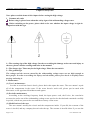
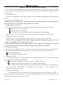
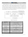
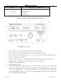
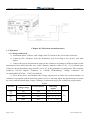
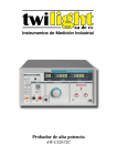
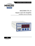
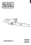
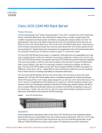
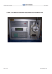
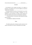
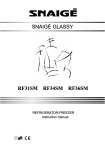
CS2670AX Voltage withstand tester
User manual
Table of Contents
Chapter 1 Safety rules……………………………………………………………………………..2
Chapter 2 what will you notice before testing…………………………………………………..4
Chapter 3 Brief introduction………………………………………………………………………5
Chapter 4 Working theory…………………………………………………………………………6
Chapter 5 Technical parameter………………………………………………………………..…6
Chapter 6 Operation Instructions and Procedures………………………………………….…7
Chapter 7 Applying Illustration …………………………………………………………………10
Chapter 8 Calibration and maintenance……………………………………………………...…11
Chapter 9 Maintenance ……………………………………………………………………………16
Page 1 of 15
www.meteronic.com
CS2670AX Voltage withstand tester
User manual
Chapter 1 safety rules
Note: please read the items of this chapter before testing the high voltage.
1.Common safe rules
Before using it, please know about the safety signs of the withstanding voltage tester.
Before switching on the power, please check to be sure whether the input voltage is right in
comparison with the sign.
1---The warning sign of the high voltage. In order to avoiding the damage to the tester and injury to
the user, please read the warnings and rules in the manual.
2---The danger sign. There may be the high voltage. Please do not touch it.
3---The ground sign.
The voltage and the current caused by the withstanding voltage tester are too high enough to
hurt people. In order to avoiding the injury and the death, please first check it carefully when
moving and using it.
2. Maintenance
(1) User’s maintenance
In order to avoid an electric shock, please don't take apart the tester. The user mustn’t repair
all of the components in the tester. If the tester doesn’t work well, please put in touch with
Meteronic or the appointed distributors and agents.
(2) Periodic maintenance
According to the working frequency band, the input power cord, the P-wire, the correlative
accessories and so on of the withstanding voltage tester need to be checked and examined carefully
in period, which can protect the user and the accuracy of the tester.
(3) Modification of the user
The user mustn’t modify the circuit and the components inside. If you did, the warrant of the
tester is invalid, and my company doesn’t take the rap. The warrant is invalid either if you use the
Page 2 of 15
www.meteronic.com
CS2670AX Voltage withstand tester
User manual
components and the accessories which are not accepted by Meteronic. If the reprocessed product
has already been modified, we will charge the maintenance costs and we will resume our design.
3. The working platform of testing
(1) Which situations are the best for the worktable?
It is important to select a suitable position for the worktable. So the place should be which the
persons accept the operator far away from. If there is no place like that, you must isolate the
worktable with the other instruments and mark it “Testing High Voltage Field”. If the worktable is
near other worktables, please mark “Danger! High voltage is being tested! Don’t stay nearby!”
(2) The input power supply
A good ground is a vital part of the withstanding voltage tester. There is a ground interface in
its back panel. Please check to be sure the ground connection has continuity. The tester must have
the independent switch fixed in well-marked position, and the function of the switch must be
marked. Once the emergency happened, cut off the power source at once, and then do with matter.
The input power of the tester is designed to be used on AC only. Its range is 220v±10%. The
frequency of the power is 50HZ. If the power in its range is instable, it maybe does harm to the
components inside or cause the tester wrong running.
Note: The fuse in the tester must be a rapid melting model.
(3) The working test board
When tested, the tester must be placed on the worktable, which is the non-conductor. Don’t use
the conductor between the operator and the tested device. The position of the operator is
appropriate. Don’t stride the tested device to operate or adjust the tester.
When operating the tester, the testing working field and around it don’t contain fuel gas or the
inflammable matter which can cause the explosion and fire hazard.
(4) Operator
The electric shock can cause the injury even death to the user when the wrong operation has
been done. So it is important to train the suitable staff to use and operate the tester. The clothes of
the operator mustn’t contain the metal. And don’t wear the metal, either such as the watch, i.e...
The persons who have the heart disease or carries the rate adjuster mustn’t operate the tester.
(5) The essential point of safety
The operator who is not fit for the job and the person who is incoherent with the job must
far away from the test field.
Keep the test field in order and in safety at any time.
Note: Don’t touch the tested device or the devices, which are connected with it when testing.
Once any problems to the tester turned up, please cut off the high voltage output and input
power.
After testing, please discharge first, and then remove the P-wire.
Page 3 of 15
www.meteronic.com
CS2670AX Voltage withstand tester
User manual
Chapter 2 what will you notice before testing
The output of the withstanding voltage tester can output 10kV, the highest voltage. Any false
operation will result in the misadventure even death. So please read this chapter carefully with the
view of safety.
1. An electric shock
In order to avoiding the electric shock, please wear the rubber-insulated gloves before using the
tester.
2. The tester is in the testing state
When the tester is running in the testing state, the P-wire, the tested device, the test probe and
the output port all carry the high voltage. Please don’t touch!
3. Changing the tested device
After finishing testing, when you change another tested device, please check to be sure:
The tester is in the reset state.
The test light is not flicking.
The figure of the voltage in the liquid-crystal display is not changing.
Especially notice: Don’t touch the high voltage probe when changing the tested device.
4. Switch on or off the power switch
Once the power is cut off, please wait for a minute if you want to start it once more.
Caution: It is very dangerous in the high voltage output state to change the power state, “on”
or “off”, continuously. It also do harm to the tester.
Don’t join the output port of the high voltage with any things when switching on or off the
power for it maybe cause the abnormal high voltage output which is very hazard.
5. Emergency treatment
In order to avoiding the more loss, please do according to the following way under any
emergent conditions such as an electric shock, the burning of the tested device or the host:
First cut off the power.
Then unplug the plug of the power.
6. Trouble occurring
The following situations are very dangerous. Be careful please! Because it may still output the
high voltage even you press the “RESET”.
The test light is still going on when presses the “RESET” down.
The voltmeter shows no readout while the test light is still going on.
When one of the situations occurs, please cut off the power and unplug its plug, and don’t
use it any more. The trouble is very dangerous. Please bring it to our company or the
business-acted place to repair.
7. Trouble of the test light
The voltmeter shows the readout while the test light doesn’t light after the “TEST” is
pressed. This state may be the trouble of the test light. Please make the tester off and bring it to our
company or the business-acted place to repair.
Page 4 of 15
www.meteronic.com
CS2670AX Voltage withstand tester
User manual
Chapter 3 Brief Introduction
The withstand voltage tester is an instrument applied to measure the density of withstanding
voltage. It can visually, accurately, quickly and reliably tests the breakdown voltage, drain current
and other electrical security performance indices of various measured objects, and can act as DC
(AC) high voltage power supply to test the performance of components and the complete
instrument. The CS2600 withstand voltage tester product series is designed according to the
requirement of international and domestic security standards such as IEC, ISO, BS, UL, JIS and etc.
Its withstanding voltage is 3kV to 50kV, and drain current is 0 to 200 mA, which the special
requirement is determined in addition. This instrument is suitable for all kinds of white goods,
power supply, cables, transformers, connecting terminals, high-voltage Bakelite electrical
appliances, switches, outlets and plugs, motors, dishwashers, washing machines, centrifugal driers,
microwave ovens, electromagnetic machines, electronic ovens, electric firepot, electric rice
cookers, TV sets, electric fanners, medical services, chemical engineering, electronic instruments,
meters, complete machines and etc, and applied to provide the security withstand voltage
protection for a strong electricity system and to test the drain current. It is also an indispensable
withstand voltage experiment device for scientific research laboratories and technical supervision
departments.
The CS2600 series products of withstand voltage testers, based on introducing and
digesting the advanced withstand voltage testers worldwide, combine with a large number of
practical usage cases from Chinese users to enhance and improve. CS2670AX type, etc withstand
voltage testers are full digital model withstand voltage tester series products latterly developed by
our factory. Both the testing voltage and the drain current dwell time are displayed in digital,
which the technique is the first applied in China. Based on the original products, its performance is
further improved. The drain current can be continuously and optionally set from 0.1 mA to 100 mA
according to the different security standards and the different requirements of users. For the time
testing, the disadvantage, which the indication difference of the original product is a few greater, is
improved, with the digital count-down-display, the precision of dwell time is increased to above
±1%, and the testing range is improved to 99 s. Its function is richer and more practical, and the
actual drain current values of the measured object can be reflected through the drain current
display to achieve which products its withstand voltage grade is better compared with the different
lots of the similar products or different manufacturers’ products, which the security performance of
your products can be guaranteed to have no fault. At the same time, the digital displayed drain
current can be used to simultaneously display its function, and extended to measure the reverse
voltage and reverse drain current of the high voltage silicon rectifier stack, the reserve voltage and
reserve drain current of the high withstand voltage tube of a dynatron. It is a domestic leading
withstand voltage tester compared from technique performance to quality, reliability.
Page 5 of 15
www.meteronic.com
CS2670AX Voltage withstand tester
User manual
Chapter 4 Working theory
Withstand Voltage tester is made up of high voltage rise circuit, leakage current detecting
circuit and indicating meter. High voltage rise circuit can calibrate and output the required test
voltage; Leakage current is capable of setting breakdown(protection) current; Indicating meter
can directly read out the test voltage value and leakage current value( or set breakdown current
value). DUT reaches the regulated time under the effect of test voltage, and instrument cuts off
test voltage automatically or manually, once breakdown appears and leakage current goes beyond
the set breakdown current, instrument can automatically cut off the output voltage and alert to
confirm whether DUT can bear the insulation intensity test.
Chapter 5 Specifications
Specification
Output voltage(kV)AC
0-5kV±(3%+3digits)
Cutoff Current(mA)AC
0.3-2/2-20mA±(3%+3 digits)
Preset warning value range
AC(mA)
0.3-2/2-20mA±(3% +3 digits) (continue set)
Test Time
1—99s(continue set)±1%
Transformer Capacity
100VA
Output Waveform
50Hz,sine wave
Environment
Temperature:0—40°C,Humidity:≤75%,
Atmospheric pressure:101.25kPa
Dimension
315mm×165mm×250mm
Weight
15kg
Page 6 of 15
www.meteronic.com
CS2670AX Voltage withstand tester
User manual
Power
240V±10%
A
A
A
A
Accessories
50Hz±2Hz
test rods
grounding line
manual
Power Line
Chapter 6 Operation Instructions and Procedures
CS2670AX Front Panel
1、 Power switch: It’s used to control whether turn on/off the power
2、 Start:Pressing it, the test light illuminates and the instrument begins to work.
3、 Reset: Pressing it, the test light goes out or over-resistance, over-current warning stops, no
current is output at this moment.
4、 Remote control interface: Connecting with remote control test gun (optional for user).
5、 Voltage knob:Rotating it can set the output voltage to 1V-5000V;
6、 AC high voltage output ports;
7、 testing grounding ports;
8、 power failure indicator: When the tester not under the power switch, if the tester power
input look somebody up and down lines (L), middle (N) and Ground wiring is correct, then
"O" and "K" light whole - . If so lights eliminate, the power should check wiring and
ensure that wiring is correct, we can use testing equipment. When the power switch tester
press, "O" and "K" light eliminate.
Page 7 of 15
www.meteronic.com
CS2670AX Voltage withstand tester
User manual
9、 Test light:If the light illuminates, it shows current has output, contrariwise, the current has
been cut off.
10、 Fall light: When setting alarm over the measured resistance value, the lights flickered at the same time
buzzer intermittent sound - when there was stream, these continuous bright lights, the buzzer -- ring
for sustained.
11、 Voltage
displays:0—5kV;
12、 Current displays:0.3mA—20mA;
13、 Time displays: 1—99s count down.
14、 Time preset knob: It can be used to set test time.
15、 Timing switch: Turning “On”,it is timing test, test time is free set among 1—99s; While
“Off”, it is manual test.
16、 Leakage flow-way switch: pop-up to 2 mA stalls, press the switch to 20 mA stalls;
17、 Leakage current adjustment button: press preset switching, with leakage flow-way switch,
can be set 0.3 mA - 20mA leakage current arbitrary alarm value;
18、 The current preset Switches: press preset switch leakage current alarm can be set value.
2、Operation Procedures:
Operation to wear rubber insulating gloves, good seats and rubber mat at the
foot of insulation pad! Test lights extinguished only in the state without a
state of high voltage output can be connected to the test materials or
demolition operation!
In the case of close and reset, the measured object is connected when the indicator of the
voltmeter is ensured to “0” and the indicator light for testing is switched off, and its grounding line
is inserted under the earth;
1. The required testing value of leakage current is set:
(1). Press the Preset switch;
(2). Choose the range of the required alarm current;
(3). Adjust the preset potentiometer for leakage current to the required alarm value;
(4). Reset the preset switch;
2. Test Manual:
(1) The timing switch is set to the “OFF” position, the button “Activate” is pressed, and the
“Test” indicator lights. The knob “Voltage Adjustor” is screwed to the required indicator value;
(2) After the testing finished, the voltage is adjusted to the 1/2 position of the testing value and
then the button “Reset” is pressed. The voltage output is shut off and the indicator light is switched
off. It proves that the measured object is good;
(3) If the current passing the measured object is greater than the specified leakage current, the
Page 8 of 15
www.meteronic.com
CS2670AX Voltage withstand tester
User manual
instrument shut off the output voltage automatically, and simultaneously the buzzer gives out an
alarm, the overrun indicator light is activated. Here, the measured object is bad. The button “Reset”
is pressed and then the alarm can be cancelled;
3. Timing Test
(1). While the “Timing” switch is “ON”, the time preset catch plate is dialed to set the required
value of dwell time;
(2) The button “Activate” is pressed and the voltage is adjusted to the required testing value;
(3). When the timing is over, the testing voltage is shut off. It proved that the measured is good;
if the current is greater, prior to the preset time, the overrun indicator light is activated and the
buzzer gives out an alarm, and thus the measured object is bad.
4. AC Test
(1) The voltage change-over switch is pressed, and the DC step is set;
(2) The high voltage line of the measured object connects to the high voltage DC output
terminal;
(3) Continue to operate according to the above operating step 3 and 4;
(4) Caution: voltage of the high voltage DC output terminal is negative voltage;
(5) The setting range of the leakage current alarm value is from 0.3 mA to 10 mA. When the
leakage current is above 10 mA, the current automatic protection and alarm are activated.
5. Remote Control Test: (Note: When a remote control test gun is applied, the time is controlled
manually.)
Example: The timing time is set to 11 s, and the remote control test gun is used to test the
measured object. The test gun is activated till the time is over, and then the test gun will restart.
(1) The remote control testing accessories connects to the instrument, and the testing voltage
(AC/DC) is selected;
(2) The required value of testing voltage is set;
(3) The required value of leakage current testing is set;
(4) The remote control test gun connects to the measured object;
(5) The switch “Activate” on the high voltage gun is pressed to test, and while the test finish,
the switch is released. (The connection is shown on the Fig.5)
Page 9 of 15
www.meteronic.com
CS2670AX Voltage withstand tester
User manual
Chapter 7 Applying Illustration
1. Electrical machine- whole instrument’s electric intensity (Withstanding voltage intensity) test
According to the picture below to connect the Withstanding voltage tester and DUT, get
through the power supply switch, set the leakage current warning value according to the product
standard of DUT, and then test it as per the 3 or 4 th operation steps. If there is no concrete leakage
current warning value in the product standard, following formula is recommended:
I Z =k p (U/R)…………(1)
I Z ──Leakage current warning value A;
U——Test voltage,V;
R──Allowed minimum Insulation resistance value Ω;
k p ——Motion index,generally take 1.2~1.5
For instance: One electrical machine with its regulated min. IR value as 2×10 6 Ω,test voltage is
1500V。
As per formula (1),then
I Z =k p (U/R)=(1.2~1.5)×(1500/2×10 6 )
=(1.2~1.5)×0.75×10 -3 ≈ 1×10 -3 (A)
Take 1mA.
2. Transformer or electrical instrument’s electric intensity (Withstanding voltage intensity) test
According to the picture below to connect the Withstanding voltage tester with DUT, set the
leakage current warning value according to the product standard of DUT, and then test it as per the
4 or 5 th operation steps. If there is no concrete leakage current warning value in the product
standard, please calculate as formula (1) above and then set the value:
Page 10 of 15
www.meteronic.com
CS2670AX Voltage withstand tester
User manual
Chapter 8 Calibration and maintenance
1. Calibration
(1) Voltage calibration
A) Instrument states in Reset, and voltage knob is rotated to the end in anti-clockwise;
B) Connected the voltmeter with the instrument well according to the picture and table
below;
C) Choose the proper measurement range on the voltmeter according to different model of the
instrument. Please notice that the error of the voltmeter shall be within ±1.5%,if it is a hand-style
voltmeter, the measurement range shall be out of 1/3 in the graduation of staff gauge. The company
produced CS1940 Digital Voltmeter or CS2040 Withstanding Voltage Calibrator are
recommended(CS2674A、CS2674 excluded);
D) Press down Start, and calibrate the voltage output knob to make the readout numbers in
voltmeter correspond with the detecting points in List 1 and then adjust the potentiometer to make
the meter indication and high-voltage voltmeter’s indication satisfy the technology requirement.
List 1
AC/DC
AC
(kV)
DC
(kV)
Page 11 of 15
Potentiometer
Detecting
points
5kV
W4
0.5;1;3;5
10kV
W4
1;3;5;10
5kV
W5
0.5;1;3;5
10kV
W5
1;3;5;10
Voltage range
Index
3%
www.meteronic.com
CS2670AX Voltage withstand tester
User manual
(2)
Leakage current calibration
A) Connect the digital ampere meter with the precision of 1% to the Withstanding Voltage
Tester according to the below picture.
B) Set the instrument in Reset state, calibrate the voltage knob to the end in anticlockwise,
and swing the leakage current switch to 2mA level (2mA is the basic level of calibrating leakage
current).
C) Choose proper load resistance as per List 2.
List 2
Calibrating voltage is 500V
Current(mA)
0.5
1
2
5
10
20
Resistance
(kΩ/W)
1000/1
500/1
250/1
100/2
50/5
25/10
D) Put the load resistance between the input terminal and test place of the instrument in series
connected with digital amperemter (or CS2040 Withstanding Voltage Calibrator).
E) Press Start into test state; slowly calibrate the output voltage to about 500V, when the digital
ampere meter displays 1mA, then adjust potentiometer to W8 to make the ampere meter point
to1mA.
F) When it is correct in calibrating basic current of 1mA, calibrate alert gate voltage and
potentiometer to make W7 alert.
G) Check 0.5mA、2mA、5mA、10mA、20mA(Model: 70A、71A、71B、74)、0.5mA、
2mA、5mA、10mA、100mA(Model: 72C、73)and so on each point, if the alert value is within
±4%, it is eligible.
H) If some individual level goes beyond error, the 1mA alert value can be calibrate properly
according to the over-error value.
Page 12 of 15
www.meteronic.com
CS2670AX Voltage withstand tester
User manual
.
2. Maintenance
Maintenance of Withstanding Voltage Tester(Ref. to below list)
Faults
(1)Power light cannot be
bright when turned on,
and no indication and
output.
Reasons
Measurements
(1) Whether power supply is connected
well?
Connect power supply well
and test by multimeter,
there maybe 220V.
(2)Whether fuse is OK?
Change fuse
(3)Whether power switch is OK?
Change power supply
switch
(4)Whether there is about 17V AC
voltage at the output terminal of
transformer, if no, the power
transformer maybe broken.
(5)Whether rectifier diode is broken?
Change corresponding
rectifier diode
(6)Whether three-terminal Steady
pressure machine 7812 is broken?
Change 7812
(7)Whether C1~C4 capacitor is
electric short
Change relevant capacitor
(1)Keys of leakage current level flick
(2) Alert when open the
instrument
Page 13 of 15
Change power transformer
(2)LM324 is broken.
(3)Sample resistor on Leakage current
switch is open.
Press down any key
Change 324
Change relevant resistor
www.meteronic.com
CS2670AX Voltage withstand tester
User manual
(1)556 is damaged
Change 556
(2)Relative Start or Reset key is broken. Change the relevant switch
(3)Start, Reset failure
(3)The linking jack is loose on main
circuit board.
Secure the jack
(4)Lead on main circuit board is open.
Weld the lead well
556 are damaged.
Change 556
(5) Timer fails in start
when testing.
(1) Timer plug is loose.
Secure the plug
(2)4060 is broken.
Change 4060
(6) Timer cannot reset
when time is up. (Manual
operation is excluded.)
(1) Timer plug is loose.
Secure it
(2)Timer 9013 is broken.
Change 9013
(4) State in test while turn
on the machine
(3) Timer4060 is broken.
Change 4060
(1) Voltage in electric net is too low
results in power voltage too low and
power relay cannot work normally.
Use AC Steady pressure
machine or voltage
regulator
(2) Power relay is broken.
Change relay
(3) Voltage display board is broken.
Change it.
(4)High-voltage output terminal is
disconnected.
Welded it well
(5)High-voltage transformer is broken.
Change the high-voltage
transformer.
(6)Plug or connecting wire of main
circuit board is loose.
Secure the plug and
connect it well.
(8) Manual start or reset is
failed.
(1) No12V voltage
Check power section
(2)556 is broken.
Change 556
(9) Start and Reset are
failed in operation.
Start or Reset key is bad connection or
damaged.
Change relevant switch
(7) When turn on the
instrument, the test light is
bright but no voltage
display.
(1) Capacitor box is broken(D6、C6、
(10) AC/DC output voltage R3 and R4 are equipped in one plastic
cannot be adjusted and the
box.)
transformer works with
(2)High-voltage transformer is broken
noise.
(there are striking fire and have
electric short phenomenon)
(11) No voltage indication
when adjusting voltage.
Page 14 of 15
(1) Voltage regulator is broken.
Change capacitor
Chang high-voltage
transformer
Change voltage
regulator.
www.meteronic.com
CS2670AX Voltage withstand tester
(12) Indicating value and
actual value have large
error (half).
(13)No voltage display
User manual
(2)Linking plug of main circuit board
may have bad connection or open
phenomena.
Secure the plug and
connect it well.
(3) D8~D11diodes have some broken
or weak welding.
Change relevant diode
(1)D12~D15 diodes have some broken.
Change relevant diode
(2) Leakage current displaying board is
broken.
Change current displaying
board.
(3)C7 and R11 Pressure sensitive
resistor are weak welded.
Weld it well
(1)220Ω/5W resistor is open or weakly
welded
Weld the component well。
(2) Leakage current displaying board is
broken.
Change current displaying
board.
(3) 324 is broken.
Change 324.
(4) Pressure sensitive resistor has
electric shock.
Change pressure sensitive
resistor
Chapter 9 Maintenance
Maintenance:
1.
Maintenance period:The instrument is warranted to be free from use for a period of 12
months from the date of shipment to the original end users in different sales spots.
2. In this period, consumer is responsible for the maintaining fee if the instrument is
damaged by improper operation.
If you have any question, please contact us.
Contact person: Mr. Ming Stone
Hangzhou Meteronic Technology Co., Ltd.
Add.:
No. 10, 3rd Xiyuan Rd.
Hangzhou Westlake Industrial Park
Hangzhou city, Zhejiang province 310030 China
Tel.:
+86 (0)571 8894 8756
Fax:
+86 (0)571 8894 8760
Mobile: +86 137 1816 9410
Email:
[email protected]
Website: www.meteronic.com
Page 15 of 15
www.meteronic.com