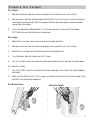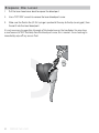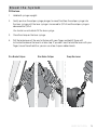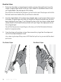
1
Road Hydraulic Brake Hose Length Adjustment and Bleed Guide 95-5018-002-000 Rev A © 2013 SRAM LLC SRAM LLC WARRANTY EXTENT OF LIMITED WARRANTY Except as otherwise set forth herein, SRAM warrants its products to be free from defects in materials or workmanship for a period of two years after original purchase. This warranty only applies to the original owner and is not transferable. Claims under this warranty must be made through the retailer where the bicycle or the SRAM component was purchased. Original proof of purchase is required. Except as described herein, SRAM makes no other warranties, guaranties, or representations of any type (express or implied), and all warranties (including any implied warranties of reasonable care, merchantibility, or fitness for a particular purpose) are hereby disclaimed. LOCAL LAW This warranty statement gives the customer specific legal rights. The customer may also have other rights which vary from state to state (USA), from province to province (Canada), and from country to country elsewhere in the world. To the extent that this warranty statement is inconsistent with the local law, this warranty shall be deemed modified to be consistent with such law, under such local law, certain disclaimers and limitations of this warranty statement may apply to the customer. For example, some states in the United States of America, as well as some governments outside of the United States (including provinces in Canada) may: a. Preclude the disclaimers and limitations of this warranty statement from limiting the statutory rights of the consumer (e.g. United Kingdom). b. Otherwise restrict the ability of a manufacturer to enforce such disclaimers or limitations. For Australian customers: This SRAM limited warranty is provided in Australia by SRAM LLC, 133 North Kingsbury, 4th floor, Chicago, Illinois, 60642, USA. To make a warranty claim please contact the retailer from whom you purchased this SRAM product. Alternatively, you may make a claim by contacting SRAM Australia, 6 Marco Court, Rowville 3178, Australia. For valid claims SRAM will, at its option, either repair or replace your SRAM product. Any expenses incurred in making the warranty claim are your responsibility. The benefits given by this warranty are additional to other rights and remedies that you may have under laws relating to our products. Our goods come with guarantees that cannot be excluded under the Australian Consumer Law. You are entitled to a replacement or refund for a major failure and for compensation for any other reasonably foreseeable loss or damage. You are also entitled to have the goods repaired or replaced if the goods fail to be of acceptable quality and the failure does not amount to a major failure. LIMITATIONS OF LIABILITY To the extent allowed by local law, except for the obligations specifically set forth in this warranty statement, in no event shall SRAM or its third party suppliers be liable for direct, indirect, special, incidental, or consequential damages. LIMITATIONS OF WARRANTY This warranty does not apply to products that have been incorrectly installed and/or adjusted according to the respective SRAM user manual. The SRAM user manuals can be found online at sram.com, rockshox.com, avidbike.com, truvativ.com, or zipp.com. This warranty does not apply to damage to the product caused by a crash, impact, abuse of the product, non-compliance with manufacturers specifications of usage or any other circumstances in which the product has been subjected to forces or loads beyond its design. 2 This warranty does not apply when the product has been modified, including, but not limited to any attempt to open or repair any electronic and electronic related components, including the motor, controller, battery packs, wiring harnesses, switches, and chargers. This warranty does not apply when the serial number or production code has been deliberately altered, defaced or removed. This warranty does not apply to normal wear and tear. Wear and tear parts are subject to damage as a result of normal use, failure to service according to SRAM recommendations and/or riding or installation in conditions or applications other than recommended. Wear and tear parts are identified as: • Dust seals • Bushings • Air sealing o-rings • Glide rings • Rubber moving parts • Foam rings • Rear shock mounting hardware and main seals • Upper tubes (stanchions) • Stripped threads/bolts (aluminium, titanium, magnesium or steel) • Brake sleeves • Brake pads • Chains • Sprockets • Cassettes • Shifter and brake cables (inner and outer) • Handlebar grips • Shifter grips • Jockey wheels • Disc brake rotors • Wheel braking surfaces • Bottom out pads • Bearings • Bearing races • Pawls • Transmission gears • Spokes • Free hubs • Aero bar pads • Corrosion • Tools • Motors • Batteries Notwithstanding anything else set forth herein, the battery pack and charger warranty does not include damage from power surges, use of improper charger, improper maintenance, or such other misuse. This warranty shall not cover damages caused by the use of parts of different manufacturers. This warranty shall not cover damages caused by the use of parts that are not compatible, suitable and/or authorised by SRAM for use with SRAM components. This warranty shall not cover damages resulting from commercial (rental) use. 3 TABLE OF CONTENTS ANATOMY............................................................................................................... 6 INTRODUCTION .................................................................................................... 7 PARTS AND TOOLS .........................................................................................................................7 HOSE SHORTENING PROCEDURE..................................................................... 8 REMOVE THE HOSE FROM THE CALIPER ........................................................................... 8 HOSE ROUTING AND LENGTH.................................................................................................. 9 COMPRESSION NUT INSTALLATION ..................................................................................... 9 HOSE INSTALLATION AT THE CALIPER ..............................................................................10 BLEED THE BRAKES .....................................................................................................................10 BLEED GUIDE ....................................................................................................... 11 PROCEDURE OVERVIEW ............................................................................................................ 11 FLUSH ................................................................................................................................................... 11 PREPARE THE SYRINGES ........................................................................................................... 12 PREPARE THE CALIPER .............................................................................................................. 13 PREPARE THE LEVER...................................................................................................................14 BLEED THE SYSTEM ..................................................................................................................... 15 WHEEL INSTALLATION ...............................................................................................................18 TEST THE SYSTEM ...............................................................................................19 MAINTENANCE ....................................................................................................19 4 TABLE OF CONTENTS SAFETY INSTRUCTIONS Brakes are a safety-critical component of a bicycle. Improper installation or use of brakes can result in loss of control of the bicycle which can lead to a crash that can cause severe injury and/or death. Follow the instructions in the user manual for proper installation. Hydraulic brakes offer increased stopping power over rim brakes and take less effort to lock-up a wheel when braking. Wheel lockup may cause you to lose control and lead to injury. Practice braking techniques on a flat level surface prior to aggressive riding. Braking effectiveness is dependent on many conditions over which SRAM has no control including: bicycle speed, braking force, condition of the bike, weight of the rider, weather, terrain, and a variety of other factors. Always ride under control. It takes longer to stop in wet conditions. To reduce the possibility of a crash avoid locking-up your wheels. SRAM hydraulic brakes are designed as a system. Do not use brake components from a manufacturer other than SRAM or Avid. Use only DOT 4 or DOT 5.1 fluids with SRAM hydraulic brakes. Do not use any other fluid, it will damage the system and make the brakes unsafe to use. Do not allow any brake fluid to contact the brake pads. If this occurs, the pads are contaminated and must be replaced. Do not allow any brake fluid to contact the braking surface. If this occurs, clean the braking surface with isopropyl alcohol. Do not touch the braking surface with your bare hands. The oils from your fingers will degrade braking performance. Always wear gloves or handle the rotor or rim by the spokes. Do not touch disc brake rotors or calipers immediately after use; they become very hot during use and could cause burns. Allow them to cool prior to making any adjustments. Disc Brakes Only: Do not use radially spoked wheels. The SRAM road hydraulic brake system is not intended for use on any motorized bicycle or vehicle. Such use could result in serious personal injury. Anatomy Hydraulic Drop Bar Lever Hood Cover Bleed Port Screw Rim Brake Caliper Disc Brake Caliper Hose Boot Compression Nut Compression Fitting Compression Nut Compression Fitting Hose Barb Hose Barb Barrel Adjuster Quick Release Banjo Bleed Port Screw Brake Pads Pad Spreader Spring Brake Pads Bleed Port Screw Brake Pad Retainer Bolt E-Clip 6 ANATOMY Introduction SRAM brakes come with the hoses attached and bled. You do not need to bleed the system prior to installation unless the hose is shortened. P a r t s a n d To o l s Safety glasses Nitrile gloves Bleed Block T10 TORX® wrench 8 mm flare nut wrench 2.5 and 4 mm hex wrench Torque wrench Avid Hand-held Hydraulic Hose Cutter Avid Bleed Kit or Avid Professional Bleed Kit Sharp pick DOT compatible grease Clean, lint-free rag Isopropyl alcohol N OT I C E - B R A K E F LU I D DOT fluids will damage painted surfaces. If any fluid comes in contact with a painted surface (e.g. your frame), wipe it off immediately and clean with isopropyl alcohol. Used DOT fluid must be recycled or disposed of in accordance to local and federal regulations. Never pour used DOT fluid down a sewage or drainage system or into the ground or body of water. INTRODUCTION 7 Hose Shortening Procedure Hose shortening must be performed at the caliper end of the hose. Remove the Hose from the Caliper 1. Disc Brake Only: Pull the boot away from the caliper to access the compression nut. 2. Use an 8 mm flare nut wrench to remove the compression nut. 3. Pull the hose from the caliper. CAUTION - E YE HAZARD DOT fluid will drip from the hose. Try to spill as little fluid as possible. Any fluid that is lost from the hose will create bubbles that will need to be removed during the brake bleed. Do not engage the brake lever while the hose is removed. Disc Brake Caliper 8 Rim Brake Caliper 8 8 HOSE SHORTENING PROCEDURE Hose Routing and Length Make sure the hose is properly routed and secured to the bicycle. Determine where you need to cut the hose by holding it up to the caliper in the position you like. Make sure to leave a gentle bend in the hose with enough length to freely turn the bars all the way from side to side. Double-check this part, because you can’t go back after you cut. Compression Nut Installation 1. Apply DOT compatible grease to the hose barb threads, the compression fitting outer surfaces, and the compression nut threads. 2. While holding the hose firmly, use a T10 TORX® wrench to thread the new hose barb into the end of the hose until it is flush. 3. Slide a new compression fitting over the end of the hose with the new hose barb. T10 HOSE ROUTING AND LENGTH 9 Hose Installation at the Caliper 1. Push the hose into the caliper until it stops. 2. While holding the hose in place, slide the compression fitting and compression nut up to the caliper or hose stop. Use your fingers to thread the compression nut into the caliper or hose stop until it stops turning. 3. While continuing to push the hose into the hose stop, use an 8 mm flare nut wrench to tighten the compression nut to 5 Nm (47 in-lb). 4. Slide the boot (if applicable) back into place. Disc Brake Caliper Rim Brake Caliper 8 8 Bleed the Brakes Cutting the hose introduces air into the system. It is necessary to bleed the brakes for optimal performance. See the next section, Bleed Guide, for instructions. 10 HOSE INSTALLATION AT THE CALIPER Bleed Guide When bleeding SRAM brakes, keep in mind you are simply forcing bubbles out of the system. Procedure Overview You will perform 3 basic operations when bleeding SRAM brakes: 1. Fill the hose 2. Bleed the caliper 3. Bleed the lever Flush When bleeding bakes, you may notice discoloration of the old fluid as it exits the system into the syringe at the lever. If the fluid is severely discolored, this indicates that the fluid is old. In this case, bleeding the system twice in order to completely remove the old fluid is recommended. Following this procedure gives you a perfectly bled, optimally performing brake. Enjoy! BLEED GUIDE 11 Prepare the Syringes 1. Fill one syringe 1/2 full of Avid High-Performance DOT Fluid and fill the other syringe 1/4 full. 2. Hold each syringe with the tip pointed up and tap the side of the syringe with your finger to bring any air bubbles to the top. Place a clean rag around the tip and slowly push the air bubbles out of the syringe. 3. De-gas the fluid in the 1/2 full syringe. Removing as many of the gas bubbles as you can from the fluid now, before pushing them into the system, will make for a better bleed. Close the syringe clamp and pull on the plunger. Bubbles will appear to form and enlarge. While the plunger is still pulled down, lightly tap the syringe to release the bubbles sticking to the sides and the bottom so that they can rise to the top of the fluid. When the bubbles stop forming and have all risen to the top, release the plunger, open the clamp, and carefully push the air out. Repeat several times. You will not be able to remove all the bubbles. 12 PREPARE THE SYRINGES Prepare the Caliper Disc Caliper 1. Remove the wheel from your bike according to the manufacturer’s instructions. . 2. Remove the e-clip from the brake pad retainer bolt. Use a 2.5 mm hex wrench to remove the brake pad retainer bolt from the caliper. Remove the brake pads and pad spreader spring from the caliper. 3. Insert the appropriate Bleed Block. This will help prevent system overfill and keep DOT fluid from contaminating your brake pads. Rim Caliper 1. Rotate the rim caliper quick release lever to the open position. 2. Remove the wheel from your bike according to the manufacturer’s instructions. 3. Rotate the rim caliper quick release lever to the closed position. 4. Turn the barrel adjuster clockwise until it stops. 5. Use a 4 mm hex wrench to remove the brake pad retainer bolts. Remove the brake pads. Disc and Rim Caliper 1. Use a T10 TORX® wrench to remove the caliper bleed port screw from the caliper body or banjo bolt. 2. Make sure the fluid in the 1/2 full syringe is pushed all the way to the tip (no air gap!), then thread it into the caliper bleed port. Disc Brake Caliper Rim Brake Caliper T10 T10 PREPARE THE CALIPER 13 Prepare the Lever 1. Pull the lever hood cover back to expose the bleed port. 2. Use a T10 TORX® wrench to remove the lever bleed port screw. 3. Make sure the fluid in the 1/4 full syringe is pushed all the way to the tip (no air gap!), then thread it into the lever bleed port. It is not necessary to reposition the angle of the brake lever on the handlebar. You may have a small amount of DOT fluid drip from the bleed port screw, this is normal. Use a clean rag to immediately wipe off any excess fluid. T10 14 PREPARE THE LEVER Bleed the System Fill the hose 1. Hold both syringes upright. 2. Gently push on the caliper syringe plunger to move fluid from the caliper syringe into the lever syringe until the lever syringe is increased to 1/2 full and the caliper syringe is decreased to 1/4 full. You should see air bubbles fill the lever syringe. 3. Close the clamp on the lever syringe. 4. Pull the brake lever all the way to the bar with your finger and hold it there until instructed to release the lever in a later step. If you don’t want to hold the lever with your finger, have a friend hold it or you can use a toe strap or rubber bands. Disc Brake Caliper Rim Brake Caliper Drop Bar Lever BLEED THE SYSTEM 15 Bleed the Caliper 1. Pull out on the caliper syringe plunger to create a vacuum, then gently push in on the caliper syringe plunger to pressurize the system. Repeat this procedure several times, until large bubbles stop coming out of the caliper. Do not pull out too hard on the plunger or you will suck air past the plunger seal into the fluid and create more bubbles that you will have to eliminate. 2. Once the large bubbles at the caliper have stopped, apply a small amount of pressure on the caliper syringe plunger and slowly let the pressure extend the brake lever you have been holding with your finger. If you fastened the lever with a toe strap or rubber bands, remove these first but keep the lever pulled in with your finger, then apply pressure on the syringe plunger. You will feel the pressure at your finger on the lever, just let the fluid extend the lever back to its original position. 3. Close the clamp on the caliper syringe, then remove the syringe from the caliper and reinstall the caliper bleed port screw. Use a clean rag to wipe off any excess DOT fluid that spills out as you reinstall the bleed port screw. Disc Brake Caliper 16 BLEED THE SYSTEM Rim Brake Caliper Bleed the Lever 1. Open the clamp on the lever syringe. 2. Pull out on the lever syringe plunger to create a vacuum, then gently push in the plunger to pressurize the system. Squeeze and release the brake lever ten times, allowing the lever to snap back to its starting position after squeezing (this helps break loose the bubbles). Repeat this procedure several times, until large bubbles stop coming out of the lever. Do not pull out too hard on the plunger or you will suck air past the plunger seal into the fluid and create more bubbles that you will have to eliminate. 3. Once the large bubbles at the lever have stopped, apply a small amount of pressure on the syringe plunger. Remove the syringe and reinstall the lever bleed port screw. Use a clean rag to wipe off any excess DOT fluid that spills out as you reinstall the bleed port screw. BLEED THE SYSTEM 17 Wheel Installation 1. Spray isopropyl alcohol onto a clean rag and wipe off the brake lever and caliper to remove any excess DOT fluid you may have missed before. 2. Remove the Bleed Block from the caliper. Reinstall the brake pads, pad spreader spring, e-clip, and brake pad retainer bolt. Use a 2.5 mm hex wrench to tighten the pad retainer bolt to 0.6-0.9 N·m (5-8 in-lb). 3. Reinstall your wheel according to the manufacturer’s instructions. For Rim Calipers: Reinstall the brake pads. Use a 4 mm hex wrench to tighten the pad retainer bolts to 5-7 N·m (44-62 in-lb). Turn the rim caliper quick release lever to the open position. Rotate the barrel adjuster counter-clockwise to open. Install your wheel according to the manufacturer’s instructions. Turn the rim caliper quick release lever to the closed position. 4. Empty the syringes into a sealed container and dispose of the fluid properly. Remember, used DOT fluid should be recycled or disposed of in accordance to local and federal regulations. Never pour DOT fluid down a sewage or drainage system or into the ground or a body of water. Do not reuse this fluid. Do not leave the syringe hose clamps closed, this will damage the clear tubing on the syringes. 18 WHEEL INSTALLATION Te s t t h e S y s t e m You are almost ready to ride, but first its a good idea to test your brakes. Pull on the lever as hard as you can imagine yourself pulling the lever while you’re riding. Make sure and look around the hose nut on the lever, and the banjo bolt on the caliper for any leaks. Make one last check of all the bolts and fittings. Maintenance To maintain optimal braking performance, bleed hydraulic brakes at least once every 6 months. Inspect brake pads for wear every month. For Disc Brakes: Replace disc brake pads when the pad thickness is 2.5 mm or less. Change the rotor when the rotor thickness is less than 1.55 mm or when changing braking material. For Rim Brakes: Use only the brake pad material recommended by your wheel manufacturer. Replace your brake pads when the grooves on your brake pads disappear. TEST THE SYSTEM 19 www.sram.com WORLD HEADQUARTERS SRAM LLC 1333 North Kingsbury, 4th floor Chicago, Illinois 60642 ASIAN HEADQUARTERS SRAM Taiwan No. 1598-8 Chung Shan Road Shen Kang Hsiang, Taichung County 429 · Taiwan EUROPEAN HEADQUARTERS SRAM Europe Paasbosweg 14-16 3862 ZS Nijkerk The Netherlands