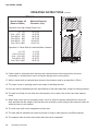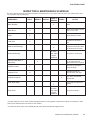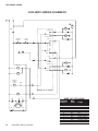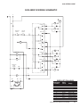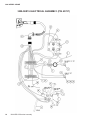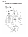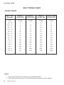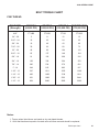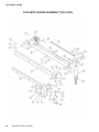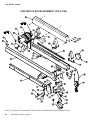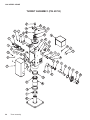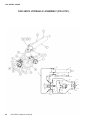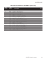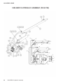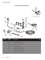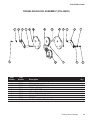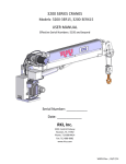
1
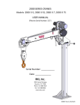
3200 SERIES CRANES
USER MANUAL
Commercial Grade
Truck Equipment
Models:
3200-3ER15
3200-3ERX15
Serial Number: ___________
Date: _____________
RKI, Inc.
2301 Central Parkway
Houston, TX. 77092
Phone: 713-688-4414
Fax: 713-688-8982
www.rki-us.com
3200 SERIES CRANE
TABLE OF CONTENTS
Description
Page
PACKING LIST . . . . . . . . . . . . . . . . . . . . . . . . . . . . . . . . . . . . . . . . . . . . . . . . . . . . . . . . . . . . . . . .
2
IMPORTANT NOTICE . . . . . . . . . . . . . . . . . . . . . . . . . . . . . . . . . . . . . . . . . . . . . . . . . . . . . . . . . . .
3
SPECIFICATIONS . . . . . . . . . . . . . . . . . . . . . . . . . . . . . . . . . . . . . . . . . . . . . . . . . . . . . . . . . . . . . .
4
OVERALL DIMENSIONS . . . . . . . . . . . . . . . . . . . . . . . . . . . . . . . . . . . . . . . . . . . . . . . . . . . . . . . .
5
3200 SERIES CAPACITY CHART . . . . . . . . . . . . . . . . . . . . . . . . . . . . . . . . . . . . . . . . . . . . . . . . .
6
INSTALLATION INSTRUCTIONS . . . . . . . . . . . . . . . . . . . . . . . . . . . . . . . . . . . . . . . . . . . . . . . . . .
7
OPERATING INSTRUCTIONS . . . . . . . . . . . . . . . . . . . . . . . . . . . . . . . . . . . . . . . . . . . . . . . . . . . .
9
LUBE & HYDRAULIC FLUID SPECIFICATIONS . . . . . . . . . . . . . . . . . . . . . . . . . . . . . . . . . . . . . . 12
INSPECTION & MAINTENANCE SCHEDULE . . . . . . . . . . . . . . . . . . . . . . . . . . . . . . . . . . . . . . . . 13
3200-3ER15 WIRING SCHEMATIC . . . . . . . . . . . . . . . . . . . . . . . . . . . . . . . . . . . . . . . . . . . . . . . . 14
3200-3ERX15 WIRING SCHEMATIC . . . . . . . . . . . . . . . . . . . . . . . . . . . . . . . . . . . . . . . . . . . . . . . 15
3200-3ER15 ELECTRICAL ASSEMBLY . . . . . . . . . . . . . . . . . . . . . . . . . . . . . . . . . . . . . . . . . . . . . 16
3200-3ERX15 ELECTRICAL ASSEMBLY . . . . . . . . . . . . . . . . . . . . . . . . . . . . . . . . . . . . . . . . . . . . 18
BOLT TORQUE CHARTS . . . . . . . . . . . . . . . . . . . . . . . . . . . . . . . . . . . . . . . . . . . . . . . . . . . . . . . . 20
3200-3ER15 BOOM ASSEMBLY . . . . . . . . . . . . . . . . . . . . . . . . . . . . . . . . . . . . . . . . . . . . . . . . . . 22
3200-3ERX15 BOOM ASSEMBLY . . . . . . . . . . . . . . . . . . . . . . . . . . . . . . . . . . . . . . . . . . . . . . . . . 24
TURRET ASSEMBLY . . . . . . . . . . . . . . . . . . . . . . . . . . . . . . . . . . . . . . . . . . . . . . . . . . . . . . . . . . . 26
3200-3ER15 HYDRAULIC ASSEMBLY . . . . . . . . . . . . . . . . . . . . . . . . . . . . . . . . . . . . . . . . . . . . . 28
3200-3ERX15 HYDRAULIC ASSEMBLY . . . . . . . . . . . . . . . . . . . . . . . . . . . . . . . . . . . . . . . . . . . . 30
INSTALLATION KIT . . . . . . . . . . . . . . . . . . . . . . . . . . . . . . . . . . . . . . . . . . . . . . . . . . . . . . . . . . . . . 32
TRAVELING BLOCK ASSEMBLY . . . . . . . . . . . . . . . . . . . . . . . . . . . . . . . . . . . . . . . . . . . . . . . . . . 33
TRAVELING BLOCK MICROSWITCH RESETTING . . . . . . . . . . . . . . . . . . . . . . . . . . . . . . . . . . . 34
LOAD SENSOR CALIBRATION - RKI 3200 SERIES CRANES . . . . . . . . . . . . . . . . . . . . . . . . . . . 35
SPARE PARTS . . . . . . . . . . . . . . . . . . . . . . . . . . . . . . . . . . . . . . . . . . . . . . . . . . . . . . . . . . . . . . . . 36
TROUBLESHOOTING . . . . . . . . . . . . . . . . . . . . . . . . . . . . . . . . . . . . . . . . . . . . . . . . . . . . . . . . . . 37
LIFETIME WARRANTY . . . . . . . . . . . . . . . . . . . . . . . . . . . . . . . . . . . . . . . . . . . . . . . . . . . . . . . . . 38
Table of contents
1
3200 SERIES CRANE
PACKING LIST 3200 SERIES CRANE
The following items are included with your RKI 3200 Series crane.
1 - Crane Assembly
1 - Crane Instruction Manual
1 - Carton with the Following Contents
1 - #45157 "Hot" Cable: Wire Asy-Switch Mstr 12"
1 - #45158 "Hot" Cable: Wire Asy-Switch Mstr 25'
1 - #45156 Switch-Mstr Cutoff
1 - #45155 Bracket-3200 Switch Mstr
1 - #43738 Ground Cable: #2 ga. X 3'
6 - #43512 Cable Retaining Clip
4 - #43739 Mounting Bolt: 5/8" x 3" gr. 8
8 - #07892 Flat Washer: 5/8"
4 - #03032 Lock Washer: 5/8"
4 - #43740 Hex Nut: 5/8" gr. 8
1 - Remote Control, Corresponding to Model Number
• #44451 - ERX 18' with E-Stop
• #44671 - ER 18' with E-Stop
2
Packing list
3200 SERIES CRANE
IMPORTANT NOTICE
RKI, Inc. cannot possibly know or even anticipate all of the varied uses and applications that may be found
for its crane products. For that reason, the company expressly disclaims any and all responsibility for the
manner and methods used by the installer of these products. The company recommends that the installer
of its crane products follow sound engineering principles and comply fully with each and every applicable
ANSI, OSHA or other safety standard.
Safety Warning: RKI, Inc. cranes are not intended to be used, or incorporated as a component of any other
equipment which may be used for the lifting or moving of people. Any such use is absolutely and categorically
contrary to RKI, Inc.'s recommendation.
INTRODUCTION:
RKI cranes are designed and manufactured to provide you years of safe, dependable performance.
This manual has been provided to give you specific information regarding the safe operation and upkeep
of your crane.
It is very important that all who operate or service the crane should begin by thoroughly reading this
manual. In addition, the supervisor, and others concerned with the operation of the crane, should read
this manual. Remember that an uninformed or careless operator can make the operation of any
equipment dangerous.
The information in this manual helps to insure that your RKI crane is installed properly and operated
safely. However it is not a definitive guide to every possible situation or circumstance. If you have any
questions or require additional information, please contact RKI.
Important notice
3
3200 SERIES CRANE
SPECIFICATIONS
Models:
3200-3ERX153200-3ER15
Moment Rating:
10,000 ft. lbs
Lift Capacities:
3,200 lbs. @
2,000 lbs. @
1,429 lbs. @
1,111 lbs. @
3
5
7
9
ft.
ft.
ft.
ft.
909 lbs. @ 11 ft.
769 lbs. @ 13 ft.
667 lbs. @ 15 ft.
Boom:
Power telescoping boom extension (ERX model only) ranges 7' to 11'. The boom angle varies from -5º
to +75º.
Manual telescoping boom extension lengths 11' to 15'. The boom angle varies from -5º to +75º.
Line Speed: Over 13.7 feet per minute for single line (first rope layer).
Multi-Functions: The crane configuration allows multiple electric and hydraulic functions to be
performed simultaneously, however, multiple hydraulic functions are not possible.
Load Sensor:
A load sensor is standard to automatically protect overload.
Anti Two-Block:
Anti two-block feature prevents extending the boom against the traveling block and breaking the wire
rope.
Winch Cable and Block:
62' of 1/4" galvanized aircraft cable is supplied with traveling block for double line operation.
Electrical:
12 V.D.C electrical solenoid valves control all the powered functions.
Safety Standards:
Meets OSHA 1910.180 requirements and ANSI B30.5 safety standards.
Specifications:
· Weight: 710 lbs. - 3200-3ERX15
571 lbs. - 3200-3ER15
· Length: 12' 1"
· Width: 1' 9"
· Height: 2' 10-1/2"
· Base Plate Dimensions: 12" x 12"
· Truck Requirements: 10,000 lbs. GVWR (Minimum)
· Jack Leg: p/n JKL1 or equivalent
4
Specifications
3200 SERIES CRANE
OVERALL DIMENSIONS
8.000"
12.000"
12.188"
∅0
0"
.25
∅1
.65
6
TY "(MI
N
P.
4 .)
10.000"
TYP.
14
.06
7"
MOUNTING HOLE PATTERN
21.250"
CRANE CENTER OF GRAVITY
3200
R
-LBS.-
0
130
0
135
60°
0
110
0
950
45°
34.500"
"Built Texas Tough"
RAWSON-KOENIG
INC.
1500
130
0
1175
105
0
900
775
30°
QUALITY PRODUCTS
R
167
5
0
160
155
0
205
0
185
0
225
0
290
2600
75°
3000
3200
3200
CAPACITY
3200
WARNING
HOISTING PERSONNEL ON
BOOM, HOOK, LOAD OR LOADLINE
WILL RESULT IN
950
800
700
15°
1450
7'
1125
9'
925
11'
775
13'
675
0°
15'
B
O
O
M
L
E
N
3
2
0
0
6'
P/N: 44094
DEATH OR SERIOUS INJURY
Never hoist personnel on boom, hook, load
or any device attached to crane or loadline.
DANGER
SCISSORS POINT
SERIOUS INJURY
Keep hands and arms
clear at all time
9.000"
75° MAXIMUM
-5° MINIMUM
14.125"
11.500"
2.875"
BOOM ELEVATION:
83.000" - FULLY RETRACTED
131.000" - INTERMEDIATE (POWER) EXTENSION
179.000" COMPLETE EXTENSION
4.125"
Overall dimensions
5
3200 SERIES CRANE
3200 SERIES CAPACITY CHART
NOTES:
1) Overload Protection Limits:
Hoist Up, Boom Extend and Boom Down
2) 2,000 lbs. Hoist Capacity
3) Use 2 Part Line Only
2576
17
16
1333
2972
15
14
1538
3200
13
943
12
1818
9
8
7
BOOM HEIGHT - FEET
10
1088
3200
11
2222
1286
770
3200
1571
2857
75°
888
60°
1050
2020
45°
1283
6
5
690
1650
30°
796
941
4
1150
15°
1479
3
3200
2
3200
2500
2000
1667
1429
1250
1111
1000
909
833
769
714
667
1
3200
R
2
3
4
5
6
7
8
9
10
11
12
13
14
15
0
0
1
BOOM RADIUS - FEET & CAPACITY - LBS
6
3200 Series capacity chart
3200 SERIES CRANE
INSTALLATION INSTRUCTIONS
1. Vehicle should meet minimum GVW rating of 10,000 lbs.
2. The crane mounting base must be capable of safely supporting the crane assembly and its maximum
capacity of 10,000 ft-lbs loading. The support structure for the mounting base must be tied directly to
the main frame members of the vehicle.
3. The vehicle must be equipped with at minimum jacklegs extending out at least 42" from the centerline
of vehicle.
4. Disconnect the ground cable from the battery.
5. Drill 4 holes with 21/32" diameter and a 1 ¼" diameter hole (center with the 4 holes) of the crane
mounting location.
6. Install crane boom support in place and adjust to its lowest position.
7. Lift crane in place and install mounting bolts with nuts and washers. Note: use only bolts, nuts and
washers provided with crane. Do not substitute.
8. Install master cut off switch bracket. Line up bracket with the two inner bolts so that bracket is on the
far side of the cabinet.
9. Tighten bolts in a criss-cross pattern, alternating until all are torqued to 200 ft-lbs (no lubrication on
threads).
10.If crane is being installed on a service or utility body, seal around all holes and bolts with silicone or
equivalent sealer.
11.Adjust the boom support to contact with the boom and secure the crane hook to the hook ring.
12.Install the power cord in the crane. Attach 12" power cord from the crane's quill to either terminal of
the master cut off switch. Connect the power cord to the other terminal of the master cut off switch
then route the cord along the vehicle's frame rail to the vehicle's battery. Care must be taken so that
the power cable is not positioned against burrs, sharp edges or anything that would chafe the cable
insulation. Cable should be supported at intervals to prevent sagging or dragging. Use rubber
grommets where the cable passes through the bulkheads.
13.Cut cable to the minimum required length and connect it to the positive post of the vehicle’s battery
with the appropriate lug or clamp connection.
14.Use the supplied ground cable to ground the crane base, mounting base, or service body to the truck
chassis. Use rubber grommets where the cable passes through bulkheads.
15.If the vehicle’s negative ground cable is grounded to the vehicle’s engine, install a second cable from
the negative post of the battery to the vehicle’s frame.
16.The vehicle should be equipped with a minimum 105-amp alternator, but larger is highly
recommended.
Installation Instructions
7
3200 SERIES CRANE
17.To check if the battery and charging system is adequate, start the vehicle’s engine and allow it to run
at a fast idle. Measure the voltage at the crane’s power connection. Minimum voltage should be 13
volts at this connection. If the measurement is less than 13 volts, replace battery, alternator, or add an
additional battery.
18.Vehicle should be running during all crane operations.
19.Circuit breakers are required for all crane installations (Distributor Furnished Item). Circuit breakers for
2000, 2500, and 3200 Series Cranes are to be 150 amps.
BATTERY
Adequate battery power is a necessity for satisfactory crane operation. Most original equipment vehicle
batteries are designed for relatively light service of vehicle operation.
On vehicles with longer distances between battery and crane, or if heavy or extended periods of operation
are anticipated, a heavy duty battery may be installed in the vehicle, or a second 12 volt battery added to
the vehicle system, in order to increase available amperage. The vehicle charging system should be
functioning properly. The battery charging system should supply a minimum of 13 volts DC at the crane
with the vehicle engine running. The voltage should not drop below 9 volts when any function of the
crane is actuated.
Normal operation of the crane should not require a second battery. However, if a second battery is used,
it should be connected to the first battery in parallel; positive post to post and negative post to post.
The vehicle battery, and second battery if used, must be grounded directly to the chassis frame. If the
vehicle battery is grounded to the engine block, a second # 2 gauge minimum ground cable must be
added from the battery to the chassis frame or engine to the chassis frame. If the body is mounted to the
truck on wood runners, or rubber mounts, a # 2 gauge ground cable must be added between the body
and the chassis frame.
Maintain a regular schedule to ensure that the battery remains in good working condition. Clean all
connections, check electrolyte levels, check for loose belts and make sure that your vehicle charging
system is operating properly.
WARNING:
1.
FEDERAL LAW (49 CFR PART 571) REQUIRES THAT THE FINAL STAGE MANUFACTURER
OF A VEHICLE CERTIFY THAT THE VEHICLE COMPLIES WITH ALL APPLICABLE
REGULATIONS. ANY MODIFICATIONS OF THE VEHICLE PRIOR TO THE FINAL STAGE ARE
ALSO CONSIDERED INTERMEDIATE STAGE MANUFACTURING AND MUST BE CERTIFIED
AS TO COMPLIANCE. THE INSTALLER IS RESPONSIBLE FOR COMPLIANCE WITH ALL
APPLICABLE FEDERAL AND STATE REGULATIONS AND REQUIRED TO CERTIFY THAT
THE VEHICLE IS IN COMPLIANCE.
2.
THE INSTALLER OF THE CRANE IS RESONSIBLE TO COMPLY WTH THE OSHA TRUCK
CRANE STABILITY REQUIREMENTS AS SPECIFIED BY 29 CFR PART 1910.180 (C), (I).
8
Installation instructions
3200 SERIES CRANE
OPERATING INSTRUCTIONS
1. Do not operate this crane unless you have thoroughly read and understand the information contained
in this manual.
2.
Cranes shall be operated only by the following qualified personnel:
a. Designated persons
b. Trainees under the direct supervision of a designated person
c. Maintenance and test personnel (when it is necessary in the performance of their duty)
d. Inspectors (crane)
3. No one other than the personnel specified in (2) above shall enter the crane’s operating area, with the
exception of persons such as supervisors, and those specific persons authorized by supervisors who
duties require them to do so, and then only in the performance of their duties and with the knowledge
of the operator or other appointed persons.
4. The operator shall be familiar with the equipment and its proper care. If adjustments or repairs are
necessary, the operator shall promptly report this to an appointed person, and shall notify the next
operator.
5. The operator at the start of each shift shall test all controls. If any controls do not operate properly,
they shall be adjusted or repaired before operations are begun.
6. Seek the best possible work site for the operation when parking the truck-mounted crane. The parking
location should be firm, dry and level ground or pavement, which can adequately reach the load by the
rated capacity of the crane.
7. The truck-mounted crane shall not be parked on uneven, rocky or muddy terrain, steep grades and
obstructed overhead locations.
8. Fully extend the outriggers out and to the ground to provide firm support and keep the truck-mounted
crane as level as possible during the operation. When operating on soft terrain use wider pads or
boards under the outrigger feet. Blocking under the outrigger feet shall be of sufficient strength to
prevent crushing, bending, or shear failure.
9. After the truck mounted crane has been properly position, engage the emergency brake and start the
engine.
10.Vehicle should be running during all crane operations.
11.If the unit is equipped with a power disconnect switch, turn on power to the crane.
12.Lower the winch to detach the crane hook from the tie-down eye.
13.Always boom up to clear the boom support before you rotate and extend boom to desired position.
14.When operated near electric power lines, no part of the crane or load enters into danger zone shown
in Figure 1.
15.For power lines rate 50 kV or below, minimum clearance between the lines and any parts of the crane
or load (including handling appendages) shall be 10 ft (3 m). For higher voltages, see Table 1.
Operating instructions
9
3200 SERIES CRANE
(CONTINUED)
OPERATING INSTRUCTIONS
(CONTINUED)
Table 1
Normal Voltage, kV
(Phase to Phase)
Minimum Required
Clearance, ft (m)
Operation near High Voltage Power Line
to
Over 50 to
Over 200 to
Over 350 to
Over 500 to
Over 750 to
50
200
350
500
750
1000
10 (3.05)
15 (4.60)
20 (6.10)
25 (7.62)
35 (10.67)
45 (13.72)
Operation in Transit With No Load and Boom Lowered
to 0.75
Over 0.75 to 50
Over 50 to 350
Over 345 to 750
Over 750 to 1000
4
6
10
16
20
(1.22)
(1.83)
(3.05)
(4.87)
(6.10)
Figure 1
16.Caution shall be exercised when working near overhead power lines because they can move
horizontally or vertically due to wind, moving the danger zone to new position.
17.While in transit with no load and boom lowered, the clearance shall be as specified in Table 1.
18.The crane is now in operating position and ready for handling the load.
19.No crane shall be loaded beyond the specifications of the load rated chart, except for testing purposes.
20.The load to be lifted is to be within the rated capacity of the crane (refer to the crane load capacity
chart).
21.When loads, which are not accurately known, are to be lifted, the person responsible for the job lift
shall ascertain that the weight of the load does not exceed the crane ratings at the maximum radius at
which the load is to be handled.
22.The hoist rope shall not be wrapped around the load.
23.The load shall be attached to the hook by means of slings or other devices of sufficient capacity.
24.The operator shall not leave the controls while the load is suspended.
10
Operating instructions
3200 SERIES CRANE
(CONTINUED)
OPERATING INSTRUCTIONS
(CONTINUED)
25.No person should be permitted to stand or pass under a suspended load.
26.Before starting to lift, the following conditions should be noted:
a. The hoist rope shall not be kinked.
b. Part lines shall not be twisted around each other.
c. The hook shall be brought over the load in such a manner as to minimize swinging.
d. The effect of ambient wind on the load and on crane stability.
27.The person directing the lift shall see that:
a. The crane is level and, where necessary, blocked.
b. The load is well secured and balanced in the sling or lifting device before it is lifted more than a
few inches.
c. The lift and swing path is clear of obstructions.
28.During lifting operations, care shall be taken that:
a. There is no sudden acceleration or deceleration of the moving load.
b. Load, boom, or other parts of the machine do not contact any obstruction.
29.Side loading of boom shall be limited to freely suspended loads. Crane shall not be used for dragging
loads sideways.
30.The operator should never carry loads over people.
31.Neither the load nor boom shall be lowered below the point where less than five full wraps of rope
remain on the winch drum.
32.When rotating the crane, sudden starts and stops shall be avoided. Rotating speed shall be such that
the load does not swing out beyond the radius at which it can be controlled. A tag or restraint line
should be used during rotation to control the load.
33.Personnel shall not be permitted to ride the bare hook or a load of material suspended from the hook.
34.Do not move the vehicle when the crane is being used.
35.The crane shall be in stowed position before traveling.
36.Make sure the remote control is properly stored in a dry area.
Operating instructions
11
3200 SERIES CRANE
LUBRICATION & HYDRAULIC FLUID SPECIFICATIONS
1.
Rotational Bearing: Lubrication Specification: Mobil grease CM-S 3200 crane
2.
Hydraulic Fluid:
a. Fluid Specification: Mobil DTE26 or equivalent premium grade hydraulic fluid
12
Lubrication & hydraulic fluid specifications
3200 SERIES CRANE
INSPECTION & MAINTENANCE SCHEDULE
Be sure to perform thorough and routine inspections and maintenance on your crane and truck just as you would with any other
very expensive and very useful tool.
COMPONENT
DAILY
WEEKLY MONTHLY
EVERY 3
MONTHS
YEARLY
X
Motor Brushes
NOTES
Check.
Cable Drum
X
Make sure the cable is wound
evenly on the drum.
Cable
X
Check for cut or broken
strands, kinking et cetera.
**
Load Hook
X
Check for any cracks or
deformation of the hook or
latch
Sheaves and Bearings
Inspect for any damage and
add grease to bearings. Make
sure the sheaves turn freely.
X
X
Or more
often under
severe
conditions
Rotational Bearing
Base Mounting Bolts &
Other Bolts
Add grease to the bearing.
Check the bolt torque for the
four mounting bolts and
tighten other bolts as required.
X
Hydraulic Hoses
X
Inspect for any damage or
leakage at fittings
Hydraulic Fluid
X
Check fluid level at the
reservoir before each shift.
Hydraulic Reservoir
Boom Wear Pads
Boom Pivot
X
X
X
Or more
often under
severe
conditions
Drain, flush, and refill with
hydraulic fluid.
Inspect pads and replace as
required
Add grease to fittings.*
* All other bushings used are made of brass impregnated with an oil and graphite compound and require no maintenance. Other
parts may be lubricated with a few drops of oil as needed.
**To extend the life of cable, clean it periodically with a wire brush and lubricate it lightly with oil.
Inspection & maintenance schedule
13
3200 SERIES CRANE
3200-3ER15 WIRING SCHEMATIC
1 2 VD C
+
-
SH
RR
ES
R OTATE R
E
I
RL
R OTATE L E F T
2 B L OC K
S WITC H
OVE R L O AD
S WITC H
H O IS T U P
F
C
A
ES
H O IS T D OWN
RU N
J
L
S TOP
B OOM U P
H O IS T U P
S1
BU
D
M
BD
B O OM D O WN
S2
H YD R AU L IC
P U MP
M OTO R
SH
H
HPM
A
S3
F
S2
S2
S1
H O IS T
M2
S3
14
M1
M O TOR
WIRE LIST (P/N 44908)
ConnectorWire
Position
Color Usage
S3
3200-3ER15 Wiring schematic
A
B
C
D
E
F
G
H
I
J
L
M
Green
N/A
Blue
Gray
Purple
Yellow
N/A
Black
Red
Orange
Pink
White
Hoist Down
N/A
Microswitch
Boom Up (BU)
Rotate RIght (RR)
Hoist Up
N/A
Common (+)
Rotate Left (RL)
Emergency Stop
Emergency Stop
Boom Down (BD)
3200 SERIES CRANE
3200-3ERX15 WIRING SCHEMATIC
1 2 VDC
+
-
SH
RR
ES
ROTATE R
E
I
RL
ROTATE L EFT
OVERL OAD
S WITCH
2 B L OC K
S WITCH
H OI S T U P
F
C
A
ES
H OIS T DOWN
RU N
J
L
S TOP
B OOM U P
H OI S T U P
S1
BU
D
M
BD
B OOM DOWN
S2
H YDRAU L IC
P U MP
MOTOR
B OOM OU T
SH
B
BO
H
HPM
G
B OOM I N
BI
A
S3
F
S2
S2
S1
H OI S T
M2
S3
M1
MOTOR
WIRE LIST (P/N 44842)
ConnectorWire
Position
Color Usage
S3
A
B
C
D
E
F
G
H
I
J
L
M
Green
Tan
Blue
Gray
Purple
Yellow
Brown
Black
Red
Orange
Pink
White
Hoist Down
Boom Out (BO)
Microswitch
Boom Up (BU)
Rotate RIght (RR)
Hoist Up
Boom In (BI)
Common (+)
Rotate Left (RL)
Emergency Stop
Emergency Stop
Boom Down (BD)
3200-3ERX15 Electrical assembly
15
3200 SERIES CRANE
3200-3ER15 ELECTRICAL ASSEMBLY (P/N 43787)
16
3200-3ER15 Electrical assembly
3200 SERIES CRANE
3200-3ER15 ELECTRICAL ASSEMBLY (P/N 43787)
ItemPart
Number Number
Description
1
07898
SCRW - CP HX 1/4CX 3/4 GR2
2
*41150
HEAT SHRINK 1” LONG
3
**43102
TERMINAL 18GA, #6 STUD
4
43263
CABLE ASY-4GA 19” LG
5
**43314
DIODE - 6 AMP 200 V AXIA
6
**43315
TERMINAL-STRIP 8 ON .38
7
43362
SCREW - PHSLT #4 0.7
8
**43363
NUT - HEX #4-40
9
43425
NUT - HEX LOCK 1/4NC
10
43452
WIRE #04 18.5” BLK SOL
11
43454
WIRE #18 24.0 BLK GROUND
12
43465
FITTINGS - .56MS PLUG HEX (TOP) 13
*43683
MICROSWITCH - 2000 SERIES
14
*43690
CABLE - #16 V03 CONDUCTR FT
15
*43699
SCREW - PHSLT #2 .75
16
*43700
NUT - HEX #2-56
17
43738
WIRE #02 36” BLK GROUND
18
**43777
TERMINAL - 2PT. JUMPER
19
43804
WIRE #04 13.5” BLK ROT
20
**43815
WIRE #18 26.0 RED SOL
21
43906
HYD VALVE ASSY
22
43912
PLUG-3200 HYD VALVE (BOTTOM)
23
*43915
WASHER - LOCK INTERNAL #2
24
44234
BRACKET - ELECTRICAL ASSY
25
44239
SOLENOID ASY CRANE
26
*44248
CORD REEL 3200 CRANE
27
44671
CONTROL-CRN ER REM E/STP
28
44908
CONNECTOR-16 PIN ASY SKT
* INCLUDED IN CORD REEL ASSEMBLY KIT P/N 44193
**INCLUDED IN ASY. P/N 44908 (#28)
3200-3ER15 Electrical assembly
Qty
2
1
11
1
4
2
2
2
2
1
1
2
2
8
4
4
2
3
1
1
1
2
4
1
1
1
1
1
17
3200 SERIES CRANE
3200-3ERX15 ELECTRICAL ASSEMBLY (P/N 43786)
18
3200-3ERX15 Electrical assembly
3200 SERIES CRANE
3200-3ERX15 ELECTRICAL ASSEMBLY (P/N 43786)
ItemPart
Number Number
Description
1
07898
SCRW - CP HX 1/4CX 3/4 GR2
2
*41150
HEAT SHRINK 1” LONG
3
**43102
TERMINAL 18GA, #6 STUD
4
43263
CABLE ASY - 4 GA 19” LG
5
**43314
DIODE - 6 AMP 200V AXIA
6
**43315
TERMINAL STRIP 8 ON .38
7
43362
SCREW - PHSLT #4 0.7
8
**43363
NUT - HEX #4-40
9
43425
NUT - HEX LOCK 1/4NC
10
43452
WIRE #4 18.5” BLK (SOL)
11
43454
WIRE #18 24.0 BLK GROUND
12
*43683
MICROSWITCH - 2000 SERIES
13
*43690
CABLE - #16 V03 CONDUCTR FT
14
*43699
SCREW - PSLT #2 .75
15
*43700
NUT - HEX #2-56
16
43738
WIRE #2 36” BLK GROUND
17
**43777
TERMINAL - 2PT. JUMPER
18
43804
WIRE #4 13.5” BLK ROT
19
43815
WIRE #18 26” RED (SOL)
20
43906
HYD VALVE ASSY
21
*43915
WASHER - LOCK INTERNAL #2
22
44234
BRACKET - ELECTRICAL ASSY
23
44239
SOLENOID ASY CRANE
24
*44248
CORD REEL 3200 CRANE
25
44451
CONTROL - ERX W/ EMER STOP
26
44842
HARNESS - ELECT 3200 ERX
* INCLUDED IN CORD REEL ASSEMBLY KIT P/N 44193
**INCLUDED IN ASY P/N 44842 (#26)
3200-3ERX15 Electrical assembly
Qty
2
1
13
1
6
2
2
2
2
1
1
2
8
4
4
2
5
1
1
1
4
1
1
1
1
1
19
3200 SERIES CRANE
BOLT TORQUE CHART
COARSE THREAD
BOLT SIZE
(Strength)
GRADE 2
(60,000 PSI)
GRADE 5
(105,000 PSI)
GRADE 8
SOCKET HEAD
(150,000 PSI) (170,000 PSI)
UNC
FT-LBS
FT-LBS
FT-LBS
FT-LBS
1/4" - 20
5
7
10
11
5/16" - 18
9
15
21
23
3/8" - 16
17
27
38
41
7/16" - 14
27
43
60
65
1/2" - 13
40
65
92
99
9/16" - 12
58
94
133
138
5/8" - 11
81
130
184
191
3/4" - 10
90
230
326
338
7/8" - 9
146
372
526
546
1" - 8
218
558
788
818
1 1/8" - 7
309
695
1116
1159
1 1/4" - 7
436
981
1575
1635
1 3/8" - 6
572
1286
2065
2144
1 1/2" - 6
759
1707
2740
2845
Notes:
1. Torque values listed above are based on dry and plated threads.
2. A bolt that has been torqued to its rated value and then removed should be replaced.
20
Bolt torque chart
3200 SERIES CRANE
BOLT TORQUE CHART
FINE THREAD
BOLT SIZE
(Strength)
GRADE 2
(60,000 PSI)
GRADE 5
(105,000 PSI)
GRADE 8
SOCKET HEAD
(150,000 PSI) (170,000 PSI)
UNF
FT-LBS
FT-LBS
FT-LB
FT-LBS
1/4" - 28
5
11
12
13
5/16” - 24
10
22
24
25
3/8” - 24
19
40
43
46
7/16” - 20
30
62
68
73
1/2” - 20
46
96
104
112
9/16” - 18
65
137
148
154
5/8” - 18
91
192
208
216
3/4” - 16
159
336
364
378
7/8” - 14
200
534
579
601
1” - 14
244
815
883
917
1 1/8” - 12
347
1011
1252
1300
1 1/4” - 12
483
1408
1744
1811
1 3/8” - 12
651
1899
2351
2441
1 1/2” - 12
854
2490
3083
3202
Notes:
1. Torque values listed above are based on dry and plated threads.
2. A bolt that has been torqued to its rated value and then removed should be replaced.
Bolt torque chart
21
3200 SERIES CRANE
3200-3ER15 BOOM ASSEMBLY (P/N 43785)
22
3200-3ER15 Boom assembly
3200 SERIES CRANE
3200-3ER15 BOOM ASSEMBLY (P/N 43785)
ItemPart
Number Number
Description
1
03029
.375 WASHER - LOCK
2
07756
SCRW - CP HX 1/4C x 2.5"
3
07882
WASHER - LOCK 1/4"
4
07885
WASHER - FLAT 3/8
5
07887
WASHER - FLAT 7/16
6
40080
GREASE FITTING
7
40911
SCRW - CP HX 5/16Cx3/4
8
41013
SCREW - CPSKT 0.25 0.5
9
43041
PULLEY - 4.00D .75BORE
10
43135
SCREW - CAP SKT.25" x 1.75"
11
43139
RING - RTNG EXT 0.750 1P
12
43166
PIN - GRVD 0.75 1.37
13
43331
SPACER - BOOM 3200 & 6000
14
43345
PIN - QUICK 1.00 4.00 W/L 15
43425
NUT - HEX LOCK 1/4NC
16
43634
CLAMP - LOOM .375 I.D.
17
43751
PIN - KPR 0.75 1.62 / 3200
18
43753
PIN - W/KPR 1.00 2.24 / 3200
19
43783
SPACER - 3200 EXT BOOM
20
43820
BOOM - 3200-3ER15 MAIN
21
43821
BOOM - 3200-3ER15 INT
22
43831
WASHER - FENDER 3/8 PLATED
23
43834
WIRE ROPE 1/4" 7x19 GALV.
24
43909
SPACER - 3200 BOOM HEAD
25
43986
WASHER - FLAT 1/4 SAE
26
44009
POINTER - DEGREE INDICATOR
27
44031
SCRW-CP HX 3/8 - 16 x .7
28
44085
CAGE - WIRE TWO BLOCK - 3200
29
44086
MICROSWITCH HOUSING
30
44088
BOOM - 3200-3ER15 EXT
31
44090
P-CR 3200 ER TRAV BLOCK
32
44102
SCRW - CP HX 1/4Cx1-1/2
33
44112
WASHER - FENDER 3/8 PLATED
34
44248
CORD REEL 3200 CRANE
35
44249
EYE BOLT .25 - 20UNC
36
44364
WINCH WARN - ASY 3200
37
44444
CORD GUIDE 3200ER CRANE
38
44640
BRACKET - CABLE REEL
3200-3ER15 Boom assembly
Qty
4
2
12
2
6
2
4
8
2
2
2
1
2
2
4
1
2
1
1
1
1
2
1
2
8
2
2
1
1
1
1
5
1
1
2
1
1
1
23
3200 SERIES CRANE
3200-3ERX15 BOOM ASSEMBLY (P/N 43784)
36
P/N 40005
SEE NOTE 1
42
31
6
30
21
P/N 40005
SEE NOTE 1
5
17
40
8
7
13
7
1
31
1
4
5
37
3
20
29
26
26
1
30
7
39
41
23
37
26
3
29
1
7
18
40
43
7
22
1
13
4
24
29
26
1
14
7
8
15
34
28
37
35
25
29
3
10
11
8
15
38
19
8
3
15
12
33
16
10
7
1
9
4
32
2
NOTE 1: P/N 40005 IS A COMPONENT WITHIN 43705, SHOWN HERE FOR REFERENCE ONLY.
24
3200-3ERX15 Boom assembly
27
3
3200 SERIES CRANE
3200-3ERX15 BOOM ASSEMBLY (P/N 43784)
ItemPart
Number Number
Description
Qty
1
03029
.375 WASHER - LOCK
8
2
07756
SCRW - CP HX 1/4C x 2.5"
2
3
07882
WASHER - LOCK 1/4"
16
4
07885
WASHER - FLAT 3/8
4
5
07887
WASHER - FLAT 7/16
6
6
40080
GREASE FITTING
2
7
40911
SCRW - CP HX 5/16C x 3/4
8
8
41013
SCREW - CPSKT 0.25 0.5
8
9
43041
PULLEY - 4.00D .75BORE
2
10
43135
SCREW - CAP SKT.25" x 1.75"
2
11
43139
RING - RTNG EXT 0.750 1P
2
12
43166
PIN - GRVD. 0.75 1.37
1
13
43331
SPACER - BOOM 3200 & 6000
2
14
43345
PIN - QUICK 1.00 4.00 W/L
2
15
43425
NUT - HEX LOCK 114NC
4
16
43634
CLAMP - LOOM .375 I.D.
1
17
43705
BOOM - 3200-3ERX-15 MAIN (includes two 40005 Bronze Bushings) 1
18
43706
BOOM - 3200-3ERX-15 IMDT
1
19
43751
PIN - W/KPR 0.75 1.62 / 3200
2
20
43753
PIN - W/KPR 1.00 2.24 / 3200
1
21
43754
PIN - W/KPR 1.00 5.81 / 3200
1
22
43755
PIN - W/KPR 1.00 3.81 / 3200
1
23
43758
SPACER - 3200 EXT CYL HEAD
2
24
43759
SPACER - 3200 EXT CYL ROD
2
25
43783
SPACER - 3200 EXT BOOM
1
26
43831
WASHER - FENDER 3/8 PLATED
4
27
43834
WIRE ROPE 1/4" 7x19 GALV.
1
28
43909
SPACER - 3200 BOOM HEAD
2
29
43986
WASHER - FLAT 1/4 SAE
12
30
44009
POINTER-DEGREE INDICATOR
2
31
44031
SCRW - CP HX 3/8 - 16 x .7
2
32
44085
CAGE - WIRE TWO BLOCK - 3200
1
33
44086
MICROSWITCH HOUSING
1
34
44088
BOOM - 3200-3ERX-15-15 EXT
1
35
44090
P-CR 3200ERX TRAV BLOCK
1
36
44093
COVER - 3200ERX EXTEND CYL
1
37
44102
SCRW - CP HX 1/4C x 1-1/2
9
38
44112
WASHER - FENDER 3/8 PLATED
1
39
44248
CORD REEL 3200 CRANE
1
40
44249
EYE BOLT .25 - 20UNC
2
41
44258
CORD GUIDE 3200 CRANE
1
42
44364
WINCH, WARN DC2000
1
43
44640
BRACKET - CABLE REEL
1
3200-3ERX15 Boom assembly
25
3200 SERIES CRANE
TURRET ASSEMBLY (P/N 43793)
23
28
38
44
14
1
3
19
29
20
33
30
27
5
43
41
31
42
1
7
40
21
13
22
15
10
9
34
15
3
32
39
13
1
14
15
9
36
11
25
25
24
26
Turret assembly
4
21
12
6
16
34
24
10
37
17
8
26
2
14
35
18
3200 SERIES CRANE
TURRET ASSEMBLY (P/N 43793)
ItemPart
Number Number
Description
1
03029
.375 WASHER - LOCK
2
07882
WASHER - LOCK 1/4"
3
07885
WASHER - FLAT 3/8
4
40006
KEY - 08 WORM 0.18 2.37
5
40014
PLUG - 08 BRG COVER
6
40034
WORM - 08 36:1 LH
7
40078
COVER - 08 BRG
8
40082
GREASE FITTING - 1/8NPT
9
40156
BEARING - CONE 08 0.87 ID
10
40157
BEARING - CUP 08 2.12 OD
11
40605
SCREW - STSKT 0.37 0.4 OVL
12
40816
ADAPTER - HYD 08 2 BOLT A
13
40900
SCREW - CPHEX 0.25 x 0.6
14
40911
SCREW - CPHEX 0.37 0.7
15
40986
WASHER - FLAT 1/4 SAE
16
40992
WASHER - LOCK, HI-COLLAR.25"
17
41013
SCREW - CPSKT 0.25 0.5
18
41016
SCREW - CAP SKT .25" x 1.75"
19
41095
SCREW - CAP HEX HD., .25" x 1.0"
20
41124
PIN - ROLL, 0.125" x 1.000"
21
41967
GASKET - BEARING HOLDER
22
43090
NUT - HEX .250NC SELF LOG
23
43201
CONNECTOR-CABLE FEM PANL
24
43297
BEARING - CONE 3200 3.37 ID
25
43298
BEARING - CUP 3200 5.37 OD
26
43305
BASE - 3200 SERIES
27
43327
GEAR - 3200 36:1 LH
28
43336
ROD - 3200 ELEC ROD CONNECT
29
43346
PAD-MTG F/CONNECTING ROD
30
43360
SCREW - SKTHD. SHLDR - 0.5" x 1.5"
31
43704
TURRET - 3200 SERIES
32
43752
PIN - W/KPR 1.00 7.69/3200
33
43756
PIN - W/KPR 1.25 7.69/3200
34
43760
SPACER - 3200 WORM 1.57
35
43761
SPACER - 3200 TURRET ROT BRG
36
43762
COVER - 3200 TURRET REAR
37
43763
SHAFT - 08 WORM 3200 ROT
38
43767
BRACKET - 3200 CONT ROT MT
39
43768
BRACKET MICROSWITCH MTG.
40
43774
BRACKET - 3200 HOSE RING
41
43831
WASHER - FENDER 3/8 PLATED
42
44102
SCRW - CP HX 1/4C x 1-1/2
43
44343
COVER - PUMP 3200 CRANE
44
44504
SCREW - CPHEX 0.25 1.25
Qty
4
3
2
1
1
1
1
1
2
2
1
1
7
4
7
6
1
6
6
1
2
1
1
2
2
1
1
1
1
8
1
1
1
2
1
1
1
1
1
1
2
1
1
1
Turret assembly
27
3200 SERIES CRANE
3200-3ER15 HYDRAULIC ASSEMBLY (P/N 43791)
28
3200-3ER15 Hydraulic assembly
3200 SERIES CRANE
3200-3ER15 HYDRAULIC ASSEMBLY (P/N 43791)
ItemPart
Number Number
Description
1
2
3
4
5
6
7
8
9
10
11
12
13
14
15
16
17
18
40341
43368
43374
43376
43379
43465
43541
43715
43775
43779
43780
43799
43801
43802
43906
43912
44231
44232
Qty
MOTOR - HYDRAULIC 103-1028
FITTING - .56M TO .25FP ST
FITTING - .25FP TE
FITTING - .25MP .25FPS 90
FITTING - .25MP .25FP 90
FITTING - .56MS PLUG HEX (TOP)
FITTING - ADAPTER .50M TO .25F
CYLINDER - HYD. 3.00B 14.50S
FITTING - .56MS .25FPS45
HOSE - HYDRAULIC 0.25D .25MP17.2L
HOSE - HYDRAULIC 0.25D .25MP34.0L
FITTING - 56MS .25FP 90
FITTING - .25MP .25FPS9006
PUMP - HYDRAULIC 3200 SERIES 12V
VALVE - COMPL 3200 COMPACT
PLUG - 3200 HYD VALVE (BOTTOM)
HOSE - HYDRAULIC 0.25 .25MP20.0L
NIPPLE - M TO M .25 X .25
3200-3ER15 Hydraulic assembly
1
2
1
6
1
2
2
1
4
2
2
2
1
1
1
2
3
1
29
3200 SERIES CRANE
3200-3ERX15 HYDRAULIC ASSEMBLY (P/N 43790)
30
3200-3ERX15 Hydraulic assembly
3200 SERIES CRANE
3200-3ERX15 HYDRAULIC ASSEMBLY (P/N 43790)
ItemPart
Number Number
Description
1
2
3
4
5
6
7
8
9
10
11
12
13
14
15
16
17
18
19
20
21
40341
43368
43374
43375
43376
43379
43541
43708
43715
43775
43779
43780
43781
43799
43801
43802
43906
44126
44184
44231
44232
Qty
MOTOR - HYDRAULIC 103-1028
FITTING - .56M TO .25FP ST
FITTING - .25FP TE
FITTING - .25MP .37TB 90
FITTING - .25MP .25FPS 90
FITTING - .25MP .25FP 90
FITTING - .50MP .25FP ST
CYLINDER - HYD. 2.00B 48.00S
CYLINDER - HYD 3.00B 14.50S
FITTING - .56MS .25FPS45
HOSE - HYDRAULIC 0.25D .25MP17.2L
HOSE - HYDRAULIC 0.25D .25MP34.0L
HOSE - HYDRAULIC 0.25D .25MP50.0L
FITTING - 56MS .25FP 90
FITTING - .25MP .25FPS9006
PUMP - HYDRAULIC 3200 SERIES 12V
VALVE - COMPL 3200 COMPACT
TUBE - 3200 HYDRAULIC CYLINDER EXTEND
FITTING - 45° SWIVEL ELBOW, 0.25 MALE PIPE TO 0.25 FEMALE PIPE
HOSE - HYDRAULIC 0.25 .25MP20.0L
NIPPLE - M TO M .25 X .25
3200-3ERX15 Hydraulic assembly
1
2
2
2
6
1
2
1
1
6
2
2
2
2
2
1
1
1
1
3
2
31
3200 SERIES CRANE
Installation Kit (P/N 43746)
ITEM PART # DESCRIPTION
QTY
1
03032 WASHER-LOCK 5/8
4
2
07892 WASHER-FLT 5/8 W
8
3
43512 CLIP-BODY F/BATTERY CABL
6
4
43738 WIRE ASY-#02 36.0 GRND
1
5
43739 BOLT-HX 5/8-11X3 G8
4
6
43740 NUT-HX 5/8-11 G8
4
7
45155 BRACKET-3200 SWITCH MSTR
1
8
45156 SWITCH-MSTR CUTOFF
1
9
45157 WIRE ASY-PWR CRANE 12"
1
10
45158 WIRE ASY-PWR BATTERY 25'
1
11
45174 FACEPLATE-SWITCH MSTR
1
12
*43211 CONNECTOR-CABLE FEM SKT
1
* INCLUDED IN CRANE POWER WIRE ASY (45157)
SWITCH ASSEMBLED TO BRACKET
12
5
2
9
1
7
2
6
10
4
11
8
3
ItemPart
Number Number
Description
1
03032
WASHER-LOCK 5/8
2
07892
WASHER-FLT 5/8 W
3
43512
CLIP-BODY F/BATTERU CABL
4
43738
WIRE ASY-#02 36.0 GRND
5
43739
BOLT-HX 5/8-11X3 G8
6
43740
NUT-HX 5/8-11 G8
7
45155
BRACKET-3200 SWITCH MSTR
8
45156
SWITCH-MSTR CUTOFF
9
45157
WIRE ASY-PWR CRANE 12"
10
45158
WIRE ASY-PWR BATTERY 25'
11
45174
FACEPLATE-SWITCH MSTR
12
*43211
CONNECTOR-CABLE FEM SK
*INCLUDED IN CRANE POWER WIRE ASY
32
Installation Kit
Qty
4
8
6
1
4
4
1
1
1
1
1
1
3200 SERIES CRANE
TRAVELING BLOCK ASSEMBLY (P/N 44090)
1
3
7
2
2
10
5
10
9
4
8
6
9
6
1
7
3
ItemPart
Number Number
Description
1
03029
.375 WASHER - LOCK
2
07756
SCRW - CP HX 1/4C X 2.5"
3
07885
WASHER - FLAT 3/8
4
40911
SCRW - CP HX 5/16CX3/4
5
43041
-4.00D .75 BORE
6
43425
NUT - HEX LOCK 1/4NC
7
43750
PIN - W/KPR 0.75 2.25 / 3200
8
43819
HOOK - 2 TON SWIVEL W/L
9
43909
SPACER
10
44087
PLATE - 3200ERX TRAV BLOCK
4
Qty
2
2
2
2
1
2
2
1
2
2
Traveling block assembly
33
3200 SERIES CRANE
RKI 3200 ERX CRANE
TRAVELING BLOCK MICROSWITCH RESETTING
The microswitch located on the boom head needs to be adjusted in either of the following conditions.
• When the traveling block compresses the wire cage until it comes in contact with the boom head and all
the crane functions continue to operate.
• When the block is not in contact with the wire cage and/or boom head and all crane functions fail to
operate except rotation and lineout.
1. Make sure that the wire cage has not been damaged by being bent out of shape. The microswitch
should be aligned with the small strike plate on the wire cage. The wire cage should be centered with
the boom head as viewed from the end and hang down with approximately 3/4” to 1” space below. If it
is not, it may be reshaped by carefully bending by hand. Otherwise a new wire cage may be required.
2. If the wire cage is in good condition or has been replaced or straightened, the two socket head screws
on the microswitch housing should be loosened and the switch positioned so that it has a gap, with the
thickness of a credit card or less, between it and the small strike flat on the wire cage. Then tighten
the two microswitch housing screws firmly.
3. Test the microswitch function by either booming out or hoisting up until the traveling block comes in
contact with the wire cage. After contact with the wire cage, but before the block hits the bottom head,
all functions except rotation, boom in and hoist down should fail to operate. Now boom in or line out
and all functions should again operate.
34
Traveling Block Microswitch Resetting (282.03)
3200 SERIES CRANE
LOAD SENSOR CALIBRATION - RKI 3200 SERIES CRANES
Your RKI crane is equipped with a torque reading load sensor, which prevents overloading. If the crane’s
load capacity is exceeded, the load sensor deactivates all winch functions except rotation and hoist down.
Remove the load from the crane and the overload sensor is AUTOMATICALLY reset, returning full
function to the crane. If the load sensor gets out of adjustment, see instructions for its recalibration below.
Occasionally it may be necessary to recalibrate the load-sensing device.
The following is the proper procedure:
1. The load-sensing device is located in the upper right-hand section of the crane housing. It consists of
a micro switch fastened to a bracket, which in turn is secured to an upright bar welded into the crane
turret.
2. The plunger on the micro switch may be adjusted by means of the adjacent setscrew.
3. Loosen the nut securing the setscrew to the bar across the back of the turret.
4. Adjust the boom elevation and extension until the centerline of hook is at a position exactly 3’ from the
center of rotation, then connect a dynamometer.
5. Raise the hook by operating the “up” position switch on the control handle until the dynamometer
reads 3,200 lbs.
* If you do not have a dynamometer please see the note below.
6. Adjust the setscrew so that it rests against the end of the plunger. Turning the setscrew counterclockwise increases the load capacity while turning it clockwise decreases capacity.
7. Relieve the pull on the winch line by operating the “down” position on the control handle until the
dynamometer reads -0- lbs.
8. Again, follow the procedure in #6. When the pull reads 3,200 lbs. the load sensor should stop the
winch.
9. If the load sensor engages at the proper pull it is set correctly and the nut securing the setscrew
should be tightened.
10.If the load sensor does not engage properly follow the procedure in #6 until the proper setting is
attained.
* NOTE: If a dynamometer is not available, the same results can be obtained by using a known weight
(3,200 lbs.) and a known radius (3 ft.). Another example would be 2,000 lbs. @ 5 ft.
Load Sensor Calibration (172.05)
35
3200 SERIES CRANE
SPARE PARTS
It is recommended that repair parts for your crane be obtained from your local RKI distributor. Please note
that unauthorized servicing or alteration of your crane will void the warranty.
Each crane is assigned a serial number, which is located on the base plate. The serial number can also
be found in the owner's manual that is provided with the crane.
Please record your serial number and retain a copy of your invoice for future reference. If your crane
should need service, this information will be required.
36
Spare parts
3200 SERIES CRANE
TROUBLESHOOTING
Problem
Crane slowly stops while
lifting
Cranes only operable
functions are rotation and
hoist down
Solution
Check for weak battery or bad connctions
Load sensor gets out of
adjustment
Microswitch gets out of
adjustment
Crane will not lift load
See instructions to recalibrate.
Remote Control will not
operate
Check for any loose, exposed or frayed wires. Make sure the switches
return freely to the center position and are not sticking or loose. Inspect the
plug pins for damage.
Sporadic Functions
Check the hot cable connections from the power source to the crane. (This
includes the quick disconnect and the connection to the brass rod in the
crane.) Check for proper ground with good clean metal to metal
connections (no paint, etc.). With the truck engine running, check the
power source to confirm the crane is receiving 13 volts for proper
operations. A replacement battery, alternator or adding an additional battery
may be necessary.
Overload sensor may be set off. Lower load to ground and switch will
automatically reset.
If power boom is extended, check the boom head to determine if wire cage
is in contact with microswitch. If there is contact, all functions can be
returned tby either hoisting down or retracting the boom in.
See instructions for traveling block microswitch resetting.
Load may exceed crane capacity. Refer to the load chart. You may need to
reposition the truck closer to the load. Check microswitches (in turret and
at the end of the boom) by pressing the point on the microswitch. If it does
not click, replace the microswitch.
Always provide the serial number of the crane (stamped on baseplate) for further troubleshooting
questions.
Troubleshooting
37
3200 SERIES CRANE
RKI
LIFETIME WARRANTY
This warranty applies to anything we have manufactured.
The warranty applies to the original owner of the product for as long as he or she owns the product.
If something goes wrong which we determine was our fault we will repair or replace your product. The
warranty doesn't apply to normal wear and tear.
Be sure to call your local distributor if you have a problem. We need the opportunity to talk to you about
it. We may ask you to email us pictures or ship the product back to us for inspection.
Parts that we use but don't manufacture are covered to the extent of the warranty we get from the
company that does manufacture them.
No loss of use coverage. No freight coverage. Repairs have to be authorized by us, in writing, in
advance. No coverage if the product has been changed in any way.
To qualify for warranty the product must have been treated with respect in regard to normal installation,
maintenance, and usage.
Accidents and acts of God aren't covered.
This warranty will be in effect until we decide to change it.
38
Merchandise return policy
3200 SERIES CRANE
NOTES
Notes
39
R
Other RKI Quality Products
> Aluminum Treadplate and Steel Truck Boxes for
Pick-Up Trucks and Flatbeds
> Canopy Bodies
> Custom Truck Boxes and Service Bodies
> Line Bodies
> Saddle Compartments
> Service Bodies
> Space Packs
> Versatile Storage Systems
> Window Grilles
RKI manufactures special cranes - consult your
nearest dealer with your custom needs.
IN ORDER TO PROVIDE YOU WITH THE MOST INNOVATIVE AND
PROGRESSIVE EQUIPMENT, SPECIFICATIONS, AND DESIGNS ARE
SUBJECT TO CHANGE WITHOUT NOTICE.
01/13
www.rkius.com
RKI, Inc.
2301 Central Parkway
Houston, Texas 77092
713.688.4414
FAX: 713.688.8982