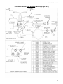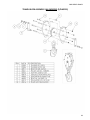
1
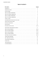
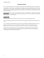
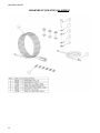
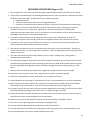
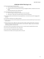
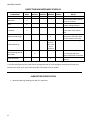
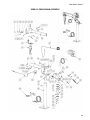
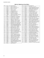
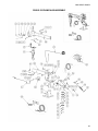
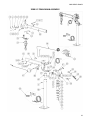
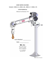
2000 SERIES CRANES
Models: 2000-3-5, 2000-3-5S, 2000-3-7, 2000-3-7S
USER MANUAL
Effective Serial Number: 5271
Serial Number: ___________
Date: _____________
RKI, Inc.
2301 Central Parkway
Houston, TX. 77092
Phone: 713-688-4414
Fax: 713-688-8982
www.rkius.com
W0037 Rev A, 01/16/15
2000 SERIES CRANES
TABLE OF CONTENTS
Description
Page(s)
PACKING LIST . . . . . . . . . . . . . . . . . . . . . . . . . . . . . . . . . . . . . . . . . . . . . . . . . . . . . . . . . . . . . . . . . . . . . .
2
IMPORTANT NOTICE . . . . . . . . . . . . . . . . . . . . . . . . . . . . . . . . . . . . . . . . . . . . . . . . . . . . . . . . . . . . . . . .
3
SPECIFICATIONS . . . . . . . . . . . . . . . . . . . . . . . . . . . . . . . . . . . . . . . . . . . . . . . . . . . . . . . . . . . . . . . . . . . .
4
2000-3-5 OVERALL DIMENSIONS . . . . . . . . . . . . . . . . . . . . . . . . . . . . . . . . . . . . . . . . . . . . . . . . . . . . . .
5
2000-3-5S OVERALL DIMENSIONS . . . . . . . . . . . . . . . . . . . . . . . . . . . . . . . . . . . . . . . . . . . . . . . . . . . . .
6
2000-3-7 OVERALL DIMENSIONS . . . . . . . . . . . . . . . . . . . . . . . . . . . . . . . . . . . . . . . . . . . . . . . . . . . . . .
7
2000-3-7S OVERALL DIMENSIONS . . . . . . . . . . . . . . . . . . . . . . . . . . . . . . . . . . . . . . . . . . . . . . . . . . . . .
8
CAPACITY CHART . . . . . . . . . . . . . . . . . . . . . . . . . . . . . . . . . . . . . . . . . . . . . . . . . . . . . . . . . . . . . . . . . . .
9
RECOMMENDED MOUNTING IN PICKUP BED . . . . . . . . . . . . . . . . . . . . . . . . . . . . . . . . . . . . . . . . . . . .
10
INSTALLATION INSTRUCTIONS . . . . . . . . . . . . . . . . . . . . . . . . . . . . . . . . . . . . . . . . . . . . . . . . . . . . . . . .
11
BATTERY & GROUNDING . . . . . . . . . . . . . . . . . . . . . . . . . . . . . . . . . . . . . . . . . . . . . . . . . . . . . . . . . . . . .
12
MOUNTING KIT . . . . . . . . . . . . . . . . . . . . . . . . . . . . . . . . . . . . . . . . . . . . . . . . . . . . . . . . . . . . . . . . . . . . .
13
OPERATING INSTRUCTIONS . . . . . . . . . . . . . . . . . . . . . . . . . . . . . . . . . . . . . . . . . . . . . . . . . . . . . . . . . . 14-16
INSPECTION & MAINTENANCE SCHEDULE . . . . . . . . . . . . . . . . . . . . . . . . . . . . . . . . . . . . . . . . . . . . . .
17
2000-3-5 MAIN ASSEMBLY . . . . . . . . . . . . . . . . . . . . . . . . . . . . . . . . . . . . . . . . . . . . . . . . . . . . . . . . . . . 18-19
2000-3-5S MAIN ASSEMBLY . . . . . . . . . . . . . . . . . . . . . . . . . . . . . . . . . . . . . . . . . . . . . . . . . . . . . . . . . . . 20-21
2000-3-7 MAIN ASSEMBLY . . . . . . . . . . . . . . . . . . . . . . . . . . . . . . . . . . . . . . . . . . . . . . . . . . . . . . . . . . . 22-23
2000-3-7S MAIN ASSEMBLY . . . . . . . . . . . . . . . . . . . . . . . . . . . . . . . . . . . . . . . . . . . . . . . . . . . . . . . . . . . 24-25
ELECTRICAL LAYOUT (ALL MODELS) . . . . . . . . . . . . . . . . . . . . . . . . . . . . . . . . . . . . . . . . . . . . . . . . . . . . 26-27
1
TRAVEL BLOCK ASSEMBLY . . . . . . . . . . . . . . . . . . . . . . . . . . . . . . . . . . . . . . . . . . . . . . . . . . . . . . . . . . .
28
ANTI TWO-BLOCK SYSTEM . . . . . . . . . . . . . . . . . . . . . . . . . . . . . . . . . . . . . . . . . . . . . . . . . . . . . . . . . . .
29
LOAD SENSOR CALIBRATION . . . . . . . . . . . . . . . . . . . . . . . . . . . . . . . . . . . . . . . . . . . . . . . . . . . . . . . . . .
29
SPARE PARTS . . . . . . . . . . . . . . . . . . . . . . . . . . . . . . . . . . . . . . . . . . . . . . . . . . . . . . . . . . . . . . . . . . . . . .
30
TROUBLESHOOTING . . . . . . . . . . . . . . . . . . . . . . . . . . . . . . . . . . . . . . . . . . . . . . . . . . . . . . . . . . . . . . . .
31
LIFETIME WARRANTY . . . . . . . . . . . . . . . . . . . . . . . . . . . . . . . . . . . . . . . . . . . . . . . . . . . . . . . . . . . . . . . .
32
2000 SERIES CRANES
PACKING LIST
The following items are included with your RKI 2000 Series crane:
1 – Crane Assembly
1 – Crane User Manual (W0037)
1 – Carton with the following contents, including Mounting Kit (43745) and other components:
1 – “Hot” Quill Power Cable (43295): 25ft #2ga Wire Assembly
1 –Ground Cable (43738): 3ft #2ga Wire Assembly from Service Body to Vehicle Frame
6 –Cable Retaining Clips (43512)
4 –Mounting Bolts (19152): ½-13 x 2-½” Grade 8
8 –Flat Washers (07889): ½”
4 –Lock Washers (03030): ½”
4 –Hex Nuts (43520): ½-13 Grade 8
1 – Remote Control (45148): 12’ heavy duty
2
2000 SERIES CRANES
IMPORTANT NOTICE
RKI, Inc. cannot possibly know or even anticipate all of the varied uses and applications that may be found for its
crane products. For that reason, the company expressly disclaims any and all responsibility for the manner and
methods used by the installer of these products. The company recommends that the installer of its crane
products follow sound engineering principles and comply fully with each and every applicable ANSI, OSHA or
other safety standard.
Safety Warning: RKI, Inc. cranes are not intended to be used, or incorporated as a component of any other
equipment which may be used for the lifting or moving of people. Any such use is absolutely and categorically
contrary to RKI, Inc.'s recommendation.
INTRODUCTION:
RKI cranes are designed and manufactured to provide you years of safe, dependable performance.
This manual has been provided to give you specific information regarding the safe operation and upkeep of your
crane.
It is very important that all who operate or service the crane should begin by thoroughly reading this manual. In
addition, the supervisor, and others concerned with the operation of the crane, should read this manual.
Remember that an uninformed or careless operator can make the operation of any equipment dangerous.
The information in this manual helps to insure that your RKI crane is installed properly and operated safely.
However it is not a definitive guide to every possible situation or circumstance. If you have any questions or
require additional information, please contact RKI.
3
2000 SERIES CRANES
SPECIFICATIONS
Models:
2000-3-5
2000-3-5S
2000-3-7
2000-3-7S
Moment Rating:
6,000 ft. lbs
Lift Capacities:
2,000 lbs. @ 3 ft.
1,500 lbs. @ 4 ft.
1,200 lbs. @ 5 ft.
1,000 lbs. @ 6 ft.
850 lbs. @ 7 ft.
Boom:
The boom angle includes lifting positions of 0°, 25°, 50°, and 75°.
Manual boom extension ranges:
(-5 models): (12” intervals) 40-13/16”, 52-13/16”, 64-13/16”
(-7 models): (17-½”) 51-13/16”, 69-5/16”, 86-13/16”
Boom is spring counterbalanced to assist in lifting and adjustment.
Boom lowers to vertical position for storage and travel.
Line Speed:
Approximately 9 feet per minute (first rope layer, double line).
Load Sensor:
A load sensor is standard to automatically protect overload.
Anti Two-Block:
Per OSHA 29 CFR Part 1926.1416(d)(3), An anti two-block feature is incorporated into the crane to prevent
damage from contact between the travel block and the boom tip.
Winch, Cable and Block:
Winch is planetary gear drive with permanent motor, providing forward and reverse operation.
25ft of 3/16" galvanized aircraft cable is supplied with traveling block with safety latch for double line operation.
Electrical:
12 VDC required to operate the electric hoist winch.
Safety Standards:
Meets OSHA 1910.180 and OSHA 1926.1441 requirements.
Specifications:
2000-3-5
2000-3-5S
Product Weight
273 lbs
247 lbs
Shipping Weight
305 lbs
279 lbs
Width
15-1/4”
15-1/4”
Height
63-5/8”
30-3/8”
Length*
55-11/16”
55-11/16”
* Overall length dimension is without the boom extended.
2000-3-7
296 lbs
328 lbs
15-1/4”
69-5/8”
66-11/16”
2000-3-7S
258 lbs
290 lbs
15-1/4”
30-3/8”
66-11/16”
4
2000 SERIES CRANES
2000-3-5 OVERALL DIMENSIONS
5
2000 SERIES CRANES
2000-3-5S OVERALL DIMENSIONS
6
2000 SERIES CRANES
2000-3-7 OVERALL DIMENSIONS
7
2000 SERIES CRANES
2000-3-7S OVERALL DIMENSIONS
8
2000 SERIES CRANES
CAPACITY CHART (ALL MODELS)
9
2000 SERIES CRANES
RECOMMENDED MOUNTING SYSTEM
2000 SERIES CRANE MOUNTED IN PICKUP BED
10
2000 SERIES CRANES
INSTALLATION INSTRUCTIONS
1. The crane mounting base must be capable of safely supporting the crane assembly and its maximum
capacity of 6,000 ft-lbs loading. The support structure for the mounting base must be tied directly to the
main frame members of the vehicle.
2. Disconnect the ground cable from the vehicle’s battery(ies).
3. Drill 4 holes (9/16” diameter on 10” square pattern) and an off-center hole (2-5/16” diameter), on the
crane mounting location. Refer to the Mounting Hole Patterns shown on the Overall Dimension pages.
4. Grind both the crane lower mounting base and the service body’s top mounting plate, removing any
paint, primer, or sealants. The crane is electrically grounded through the base plate, thus it is important
that there is a good metal-to-metal contact between the crane and the mounting location.
5. Lift crane in place and install Grade 8 mounting bolts with nuts and washers. Note: use only bolts, nuts,
and washers provided with crane. Do not substitute and do not reuse bolts that have been previously
torqued.
6. Tighten Grade 8 bolts in a criss-cross pattern, alternating until all are torqued to 95 ft-lbs (dry bolt).
7. If crane is being installed on a service or utility body, seal around all holes and bolts with silicone or
equivalent sealer. Also seal around crane mounting plate.
8. Connect the 25ft power cord to the crane’s quill then route the cord along the vehicle’s frame rail to the
vehicle’s battery. Care must be taken so that the power cable is not positioned against burrs, sharp edges
or anything that would chafe or cut the cable insulation. The cable should be supported at intervals to
prevent sagging or dragging. Use rubber grommets when cable passes through bulkheads.
9. Cut cable to the minimum required length and connect it to the positive post of the vehicle’s battery with
the appropriate lug or clamp connection.
10. Use the supplied 3ft ground cable to ground the crane base, mounting base, or service body to the truck
chassis. Use rubber grommets where the cable passes through bulkheads.
11. If the vehicle’s negative ground cable is grounded only to the vehicle’s engine, then install a second
ground cable from the negative post of the battery to the vehicle’s frame.
12. The vehicle should be equipped with a minimum 125-amp alternator, but a larger capacity is highly
recommended. Note: alternator performance is significantly affected by vehicle RPM and temperature.
At standard truck idle speeds, the alternator output can be as low as half of rated capacity.
13. The vehicle should be running during crane operation, and it is recommended that it run at an elevated
idle.
14. A 150-amp circuit breaker is required for all crane installations (not included).
11
2000 SERIES CRANES
BATTERY
Adequate battery power is a necessity for satisfactory crane operation. Most original equipment vehicle
batteries are designed for relatively light service of vehicle operation.
On vehicles with longer distances between battery and crane, or if heavy or extended periods of operation
are anticipated, a heavy duty battery may be installed in the vehicle, or a second 12 volt battery added to the
vehicle system, in order to increase available amperage. The vehicle charging system should be functioning
properly. The battery charging system should supply a minimum of 13 volts DC at the crane with the vehicle
engine running. The voltage should not drop below 9 volts when any function of the crane is actuated.
It should also be noted that the performance of vehicle’s alternators drops significantly with running idle
speed and ambient temperature. At standard truck idle speeds, the alternator output can be as low as half of
the rated capacity. So it is recommended that the vehicle be running at an elevated idle during crane
operation.
Normal operation of the crane should not require a second battery. However, if a second battery is used, it
should be connected to the first battery in parallel; positive post-to-post and negative post-to-post.
GROUNDING
Proper and adequate grounding of the crane is necessary to prevent poor performance or malfunction. The
2000 Series cranes are grounded through the bottom mounting plate. A good ground must be established
between the crane’s lower mounting base and the vehicle battery. For service or utility body mounting, this
grounding typically goes through the service body mounting plate, to the service or utility body, and then to
the vehicle frame. Ensure that a good metal-to-metal contact is made between the crane’s lower base and
the service body mounting plate. If the body is mounted to the truck on wood runners, or rubber mounts, a #
2 gauge ground cable must be added between the body and the chassis frame.
The vehicle battery, and second battery if used, must be grounded directly to the chassis frame. If the
vehicle battery is grounded to the engine block, a second # 2 gauge minimum ground cable must be added
from the battery to the chassis frame or the engine to the chassis frame. .
Maintain a regular schedule to ensure that the battery remains in good working condition. Clean all connections,
check electrolyte levels, check for loose belts and make sure that your vehicle charging system is operating
properly.
WARNING:
1. FEDERAL LAW (49 CFR PART 571) REQUIRES THAT THE FINAL STAGE MANUFACTURER OF A VEHICLE
CERTIFY THAT THE VEHICLE COMPLIES WITH ALL APPLICABLE REGULATIONS. ANY MODIFICATIONS
OF THE VEHICLE PRIOR TO THE FINAL STAGE ARE ALSO CONSIDERED INTERMEDIATE STAGE
MANUFACTURING AND MUST BE CERTIFIED AS TO COMPLIANCE. THE INSTALLER IS RESPONSIBLE
FOR COMPLIANCE WITH ALL APPLICABLE FEDERAL AND STATE REGULATIONS AND REQUIRED TO
CERTIFY THAT THE VEHICLE IS IN COMPLIANCE.
2. THE INSTALLER OF THE CRANE IS RESPONSIBLE TO COMPLY WITH THE OSHA TRUCK CRANE
STABILITY REQUIREMENTS AS SPECIFIED BY 29 CFR PART 1910.180(c)(i).
12
2000 SERIES CRANES
MOUNTING KIT (P/N 43745) (ALL MODELS)
13
2000 SERIES CRANES
OPERATING INSTRUCTIONS (Page 1 of 3)
1. Do not operate this crane unless you have thoroughly read and understand the information in this manual.
2. Cranes shall be operated only by the following qualified personnel, and crane operator certification per OSHA
29 CFR Part 1926.1427-1430 is available from local and national certifiers:
a. Designated persons
b. Trainees under the direct supervision of a designated person
c. Inspectors, maintenance and test personnel (when it is necessary in the performance of their duty)
3. No one other than the personnel specified in (2) above shall enter the crane’s operating area, with the
exception of persons such as supervisors, signal persons, and those specific persons authorized by
supervisors who duties require them to do so, and then only in the performance of their duties and with the
knowledge of the operator or other appointed persons.
4. The operator shall be familiar with the equipment and its proper care. If adjustments or repairs are
necessary, the operator shall promptly report this to an appointed person, and notify the next operator.
5. The operator at the start of each shift shall test all controls. If any controls do not operate properly, they
shall be adjusted or repaired before operations are begun.
6. Seek the best possible work site for the operation when parking the crane-mounted vehicle. The parking
location should be firm, dry and level ground or pavement, which can adequately reach the load by the rated
capacity of the crane.
7. The crane-mounted vehicle shall not be parked on uneven, rocky or muddy terrain, steep grades, or
overhead-obstructed locations.
8. Fully extend the jacklegs to the ground to provide firm support and keep the crane-mounted vehicle as level
as possible during the operation. When operating on soft terrain use wider pads or boards under the jackleg
foot. Blocking under the jackleg foot shall be of sufficient strength to prevent crushing, bending, or shear
failure.
9. After the vehicle has been properly positioned, engage the emergency brake and start the engine.
10. Connect the remote control to the crane, making sure the connector is properly engaged.
11. If the unit is equipped with a master cutoff switch, turn on power to the crane.
12. Vehicle should be running during all crane operations, and it is recommended that it run at an elevated idle.
13. When operating near electric power lines, comply with the requirements of OSHA 29 CFR Part 1426.1408.
Summarized in Figure 1 and Table 1, no part of the crane or load may enter the danger zone.
14. For power lines rate 50 kV or below, minimum clearance between the lines and any part of the crane or load
(including handling appendages) shall be 10 ft (3 m). For higher voltages, see Table 1.
15. Caution shall be exercised when working near overhead power lines because they can move horizontally or
vertically due to wind, moving the danger zone to new position.
16. While in transit with no load and boom lowered, the clearance shall be as specified in Table 1.
17. The crane is now in operating position and ready for handling the load.
18. No crane shall be loaded beyond the specifications of the load rated chart.
19. The load to be lifted is to be within the rated capacity of the crane (refer to the crane load capacity chart).
20. Pay special attention to the advisory decals attached to the crane.
14
2000 SERIES CRANES
OPERATING INSTRUCTIONS (Page 2 of 3)
Table 1
Normal Voltage, kV
(Phase to Phase)
Minimum Required Clearance
feet (meters)
Operation near High Voltage Power Line
Up to 50
10 (3.05)
Over 50 to 200
15 (4.57)
Over 200 to 350
20 (6.10)
Over 350 to 500
25 (7.62)
Over 500 to 750
35 (10.67)
Over 750 to 1000
45 (13.72)
Operation in Transit With No Load and Boom Lowered
Up to 0.75
4 (1.22)
Over 0.75 to 50
6 (1.83)
Over 50 to 350
10 (3.05)
Over 345 to 750
16 (4.88)
Over 750 to 1000
20 (6.10)
21. When loads which are not accurately known, are to be lifted, the person responsible for the job lift shall
ascertain that the weight of the load does not exceed the crane ratings at the maximum radius at which the
load is to be handled.
22. Always adjust the rotation handbrake.
23. The hoist rope shall not be wrapped around the load.
24. The load shall be attached to the hook by means of slings or other devices of sufficient capacity.
25. The operator shall not leave the controls while the load is suspended.
26. No person should be permitted to stand or pass under a suspended load.
27. Position end of boom directly over load. Do not attempt to drag a load; this may result in severe damage to
the crane.
28. Keep tension on the hoist line at all times to prevent the line from fouling on the drum.
29. Never place a chain link on the tip of the hook in order to lift a load with the winch.
30. Make sure the safety latch on the hook is closed before lifting a load.
31. Before starting to lift, the following conditions should be noted:
a. The hoist rope shall not be kinked.
b. Part lines shall not be twisted around each other.
c. The hook shall be brought over the load in such a manner as to minimize swinging.
d. The effect of ambient wind on the load and on crane stability.
15
2000 SERIES CRANES
OPERATING INSTRUCTIONS (Page 3 of 3)
32. The person directing the lift shall see that:
a. The crane is level and, where necessary, blocked.
b. The load is well secured and balanced in the sling or lifting device before it is lifted more than a few
inches.
c. The lift and swing path is clear of obstructions.
33. During lifting operations, care shall be taken that:
a. There is no sudden acceleration or deceleration of the moving load.
b. Load, boom, or other parts of the machine do not contact any obstruction.
34. Side loading of boom shall be limited to freely suspended loads. Crane shall not be used for dragging loads
sideways.
35. The operator should never carry loads over people.
36. Neither the load nor boom shall be lowered below the point where less than five full wraps of rope remain on
the winch drum.
37. When rotating the crane, sudden starts and stops shall be avoided. Rotating speed shall be such that the
load does not swing out beyond the radius at which it can be controlled. A tag or restraint line should be
used during rotation to control the load.
38. Personnel shall not be permitted to ride the bare hook or a load of material suspended from the hook.
39. Do not move the vehicle when the crane is being used.
40. The crane shall be in stowed position before traveling.
41. Make sure the remote control is properly stored in a dry area.
16
2000 SERIES CRANES
INSPECTION & MAINTENANCE SCHEDULE
COMPONENT
Motor Brushes
DAILY
Cable Drum
X
Cable
X
Load Hook
X
WEEKLY
EVERY 3
MONTHLY MONTHS
X
Sheaves and Bearings
X
X
Rotational Bearing
YEARLY
NOTES
Check
Make sure the cable is wound
evenly on the drum
Check for cut or broken
strands, kinking etcetera *
Ckeck for any cracks or
deformation of the hook or
latch
Inspect for any damage and
add grease to bearings. Make
sure the sheaves turn freely
Add grease to the bearing
Or more
often under
severe
conditions
Check the bolt torque for the
X
four mounting bolts and
tighten other bolts as required
Inspect pads and replace as
Boom Wear Pads
X
required
* To extend the life of cable, clean it periodically with a wire brush and lubricate it lightly with oil.
Base Mounting Bolts &
Other Bolts
** All other bushings used are made of brass impregnated with an oil and graphite compound and require no
maintenance. Other parts may be lubricated with a few drops of oil as needed.
LUBRICATION SPECIFICATION
1. Rotational Bearings: Mobil grease CM-S or equivalent
17
2000 SERIES CRANES
2000-3-5 CRANE MAIN ASSEMBLY
18
2000 SERIES CRANES
2000-3-5 CRANE BILL OF MATERIAL
19
2000 SERIES CRANES
2000-3-5S CRANE MAIN ASSEMBLY
20
2000 SERIES CRANES
2000-3-5S CRANE BILL OF MATERIAL
21
2000 SERIES CRANES
2000-3-7 CRANE MAIN ASSEMBLY
22
2000 SERIES CRANES
2000-3-7 CRANE BILL OF MATERIAL
23
2000 SERIES CRANES
2000-3-7S CRANE MAIN ASSEMBLY
24
2000 SERIES CRANES
2000-3-7S CRANE BILL OF MATERIAL
25
2000 SERIES CRANES
ELECTRICAL LAYOUT (ALL MODELS) (W0079) (Page 1 of 2)
26
2000 SERIES CRANES
ELECTRICAL LAYOUT (ALL MODELS) (W0079) (Page 2 of 2)
27
2000 SERIES CRANES
TRAVEL BLOCK ASSEMBLY (ALL MODELS) (P/N 45215)
28
2000 SERIES CRANES
ANTI TWO-BLOCK SYSTEM (ALL MODELS)
Your RKI crane is equipped with an anti two-block system, per OSHA 29 CFR Part 1926.1416(d)(3), to prevent
damage from contact between the travel block and the boom tip. If the travel block is allowed to contact the end
of the boom, continued operation could result in significant damage to the crane and possibly failure of the wire
rope.
When the travel block comes in contact with the rail mechanism at the end of the boom, the crane will disable
the hoist up and boom out functions. All other functions will operate as normal.
The microswitch located at the end of the boom head and the rail mechanism that engages it are pre-set at the
RKI factory. No adjustment or resetting is necessary. If either of the two following conditions exists, then the
crane requires service:
•
When the travel block compresses the rail mechanism and it comes in contact with the boom head and the
crane hoist up function continues to operate.
•
When the travel block is not in contact with the rail mechanism or the boom head and all crane functions fail
to operate, particularly hoist up and boom out.
LOAD SENSOR CALIBRATION (ALL MODELS)
Your RKI crane is equipped with a torque reading load sensor, which prevents overloading. If the crane’s load
capacity is exceeded, the load sensor deactivates the hoist up function. Remove the load from the crane and the
overload sensor is AUTOMATICALLY reset, returning full function to the crane. If the load sensor gets out of
adjustment, see instructions for its recalibration below.
Occasionally it may be necessary to recalibrate the load-sensing device.
The following is the proper procedure:
1. The load-sensing device is located in the lower front section of the crane turret housing. It consists of a
microswitch fastened to a bracket, which in turn is welded into the crane turret.
2. The plunger on the microswitch may be adjusted by means of the adjacent set screw.
3. Loosen the nut securing the set screw to the plate across the bottom of the turret.
4. With the boom retracted and in the horizontal position, connect a dynamometer (scale). In this position, the
distance from the center of the turret to the hook is approximately 41” for the 2000-3-5 & 2000-3-5S, and
approximately 52” for the 2000-3-7 & 2000-3-7S.
5. Raise the hook by operating the “hoist up” switch on the remote control until the dynamometer reads either
1,764 lbs for the 2000-3-5 & 2000-3-5S, or 1,390 lbs for the 2000-3-7 & 2000-3-7S. All 2000 series cranes are
rated for 6,000 ft-lbs of total capacity, thus different boom lengths require different load settings.
6. If a dynamometer is not available, the same results can be obtained by using a known weight (2,000 lbs.) and
a known radius (3 feet). Another example would be 1,000 lbs. @ 6 ft. Any combination where the
multiplication of the load and the radius length equates to 6,000 ft-lbs is acceptable.
7. Adjust the set screw so that it rests against the end of the plunger. Turning the setscrew counterclockwise
increases the load capacity while turning it clockwise decreases capacity.
8. Relieve the pull on the winch line by operating the “hoist down” switch on the remotel control until the
dynamometer reads 0 (zero) lbs.
9. Repeat procedure #5. When the pull reads the appropriate weight the load sensor should stop the winch.
10. If the load sensor engages at the proper pull it is set correctly and the nut securing the set screw should be
tightened.
11. If the load sensor does not engage properly follow the procedure in #5 until the proper setting is attained.
29
2000 SERIES CRANES
SPARE PARTS
It is recommended that repair parts for your crane be obtained from your local RKI distributor. Please note that
unauthorized servicing or alteration of your crane will void the warranty.
Each crane is assigned a serial number, which is stamped on a nameplate located on the side of the turret. The
serial number can also be found in the owner's manual that is provided with the crane.
Please record your serial number and retain a copy of your invoice for future reference. If your crane should
need service, this information will be required.
Below is a list of miscellaneous parts not previously listed in this manual:
Part Description
Contactor
Cover-Contactor
Motor-Winch 12V
Remote-12’ Control
Part
Number
44239
45139
44242
45148
Comment
4-Post Contactor Assembly
Cover for solenoid on Warn winch, s/n 4909 & later
Motor only, 2post
Remote, s/n 4909 & later
30
2000 SERIES CRANES
TROUBLESHOOTING
Problem
Crane slowly stops while
lifting
Cranes only operable
function is hoist down
Solution
Check for weak battery or bad connections. Remove any corrosion from both
ground and positive posts.
Overload sensor may be set off. Lower load to ground and switch will
automatically reset.
Anti Two-Block switch may be disengaged. When the travel block is not in
contact with the rail system, the rail system should be in its home position,
compressing the switch. If the rail system does not pivot freely, the anti twoblock system is not operating correctly. Contact your distributor or the RKI
factory for further assistance.
See instructions to recalibrate in this manual.
Load sensor gets out of
adjustment
Anti Two-Block microswitch The anti two-block system and its switch are preset at the RKI factory. No
gets out of adjustment
adjustment or re-setting is necessary. If the anti two-block system is not
operating correctly, contact your distributor or the RKI factory for assistance.
Crane will not lift load
Load may exceed crane capacity. Refer to the load chart. You may need to
reposition the truck closer to the load. Check microswitches (in turret and at
the end of the boom) by pressing the point on the microswitch. If it does not
click, replace the microswitch.
Remote Control will not
Check for any loose, exposed or frayed wires. Make sure the switch returns
operate
freely to the center position and is not sticking or loose. Inspect the remote
socket and connections for damage or corrosion.
Sporadic Functions
Check the hot cable connections from the power source to the crane. (This
includes the master cut-off switch, if applicable, and the connection to the
brass rod in the crane.) Check for proper ground with good clean metal to
metal connections (no paint, etc.). With the truck engine running, check the
power source to confirm the crane is receiving 13 volts for proper
operations. A replacement battery, alternator or adding an additional
battery may be necessary.
Always provide the serial number of the crane when contacting RKI for further troubleshooting questions
(stamped in the nameplate located on the side of the turret).
31
2000 SERIES CRANES
RKI LIFETIME WARRANTY
This warranty applies to anything we have manufactured.
The warranty applies to the original owner of the product for as long as he or she owns the product.
If something goes wrong which we determine was our fault we will repair or replace your product. The warranty
doesn't apply to normal wear and tear.
Be sure to call your local distributor if you have a problem. We need the opportunity to talk to you about it. We
may ask you to email us pictures or ship the product back to us for inspection.
Parts that we use but don't manufacture are covered to the extent of the warranty we get from the company
that does manufacture them.
No loss of use coverage. No freight coverage. Repairs have to be authorized by us, in writing, in advance. No
coverage if the product has been changed in any way.
To qualify for warranty the product must have been treated with respect in regard to normal installation,
maintenance, and usage.
Accidents and acts of God aren't covered.
This warranty will be in effect until we decide to change it.
32