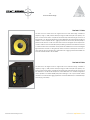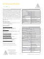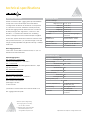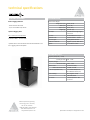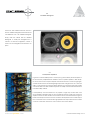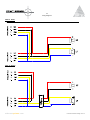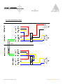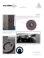
1
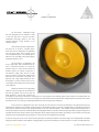
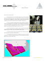
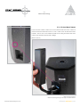
It is compulsory to read this manual before using the Point Series system. Supervision and competency are
the responsibility of the system owners and operators. All welded intersections, joints and rigging hardware
must be inspected regularly. Operators must not assume rigging has been inspected prior to use.
WARNING
Before assembling and suspending any
Adamson Point Series enclosures, the
rigger/ installer must carefully read the
Point Series operating manual and follow
safe rigging /installation instructions.
Please follow your countr y’s rigging safety
code and the venue’s recommendations
on hanging point loads.
Do not substitute with non Adamson
manufactured rigging par ts.
Using a damaged or malfunctioning unit
or a unit with missing par ts is strongly
unadvisable.
Table of Contents
Section 1.0
Intrduction and Product Details
1.0 Introduction - p. 4
1.1 Design Considerations - p.5
1.2 The Point Series Range - p.7 - 8
1.3 Product & Technical Specifications - p.9-13
1.4 Rigging Options Table - p.14
1.5 Part Numbers - p.15- 16
Section 2.0
Operation and Wiring
2.0 Rotatable Waveguide - p.17
2.1 Active/Passive Operation - p.17
2.2 Wiring Diagrams - p.18-22
Section 3.0
Rigging Parts and Terminology
3.0 SLR™ Socket - p.23
3.1 Omni Mount Threads – p. 24
3.2 SLR™ Wedger - 8, - 12, - 15 – p. 25
3.3 SLR™ Quick-Lock™ Pin & Manually Adjustable Knob- p.26
3.4 SLR™ Quick-Lock™ Vertical Bracket – p. 27
3.5 SLR™ Quick-Lock™ Horizontal Bracket – p. 28
3.6 SLR™ Quick-Lock™ Butterfly Bracket – p. 29
3.7 SLR™ Quick-Lock™ Articulator – p. 30
3.8 SLR™ Sight Mount™ Accesories - p.31
3.9 SLR™ Polemount Socket & Polemount Base for Quick-Lock™
Brackets - p.32
3.10 SLR™ C-Clamp Accesories- p.32
3.11 SLR™ Underhang Accessories- p.34
3.12 SLR™ Rigging Fasteners Chart p.35
3.13 SLR™ Rigging in Pictures p.36-38
Section 4.0
Processing, Amplification & Cabling
adamsonsystems.com
4.0 Processing , Amplification and Cabling - p.39
Point Series User Manual Page 3 of 40
1.0
Introduction
This manual is designed to give the Point Series user the necessary information
to accurately, and safely, install the Point Series range of loudspeakers in all their available
configurations.
We will cover each box in the Point Series range and take a look at the technology
involved that makes the Point Series range one of the best sounding installation speakers ranges
available today.
Point Series User Manual Page 4 of 40
Step by step rigging procedures will be included for all available Point Series rigging.
adamsonsystems.com
1.1
Design Considerations
The Point Series™ loudspeaker range
has been designed with the installation market
in mind. Our goal was to bring the innovative
loudspeaker technology utilized in the world
renowned Adamson touring products, to the
installation industry.
The Point Series has been designed from
the ground up to provide a complete solution
where point source loudspeakers are preferable
over line source arrays. When building a point
source loudspeaker system, one must pay special
attention to not only fidelity, but box output, rigging
versatility and pattern control.
The Point Series is not designed to be
hung in large arrays, where individual boxes can
rely on constructive summation to increase low
frequency output. To ensure the Point Series low
frequency drivers can maintain a high level of
low frequency energy when used as a single
source (or a small 2 or 3 box array), Adamson uses
Advanced Cone Architecture™ with Kevlar cone
geometry and cutting edge Neodymium driver
technologies to ensure maximum SPL with zero
cone fatigue, while providing minimal axial modes
in the passband.
Adamson has been on the cutting edge
of Kevlar cone technology since the mid 80s and
has been using Kevlar cones in the low and mid
band speakers for over 20 years. Combine this
technology with long excursion Neodymium magnets and you have superior power handling, greater output power and consistently stable low
end, all while keeping weight to a minimum. The low frequency driver baskets in the Point Series utilize enlarged heat sinks and thermal fins to draw
heat away from the coil, lowering it’s operating temperature and minimizing thermal compression.
Since point source loudspeakers cannot sum coherently in the way true line source arrays do (especially in the higher frequencies), they
are best used in single box or small arrays- that are focused on discrete listening areas- to minimize comb filter effects on the listening area. Since
1988, Adamson has pioneered the use of waveguides based on the work of Dr. Earl Geddes. In 1987, Geddes clearly described the geometry of
the Cylindrical, Elliptical Cylindrical and Oblate Spheroidal waveguides. Adamson has further advanced these geometries using technologies such
as Finite Element Analysis and other advanced modeling techniques, stringent testing and evaluation procedures. The use of advanced composite
materials ensure the waveguides and high frequency components are of the highest quality available.
For precise aiming and control, and to ensure as little high frequency overlap as possible, the Point Series range comes equipped with a rotatable
wave guide, that is available in three different coverage patterns to give the sound designer a number of options to achieve coverage where they
adamsonsystems.com
Point Series User Manual Page 5 of 40
1.1
Design Considerations
need to- and not where they don’t.
The Point Series also uses an innovative SLR™ rigging system, which allows individual
boxes to be pointed where they need to cover- irrespective of the positioning of other boxes
in the array. The SLR™ rigging system is highly adjustable, for precise results, using virtually
any Point Series box configuration, but is also very simple to adjust. SLR™brackets can be
“snapped” into place and then adjusted to almost any desirable coverage angle.
The look of an installation loudspeaker system is highly underrated, as installations
can be lost if the speaker system cannot blend into it’s surroundings. This is especially true
in many heritage buildings. That is why Adamson offers the Point Series in the entire range
of Pantone Color Systems, giving designers and contractors 1114 different color options to
perfectly match the speaker and SLR™ rigging accessories to the room.
All the Point Series boxes are made from 11ply 5/8” Baltic Birch for rock solid
construction and are shaped in anisometric hexagonal design to allow for use as a stage
monitor if necessary. They feature foam covered, powder coated steel grills.
In the interest in keeping costs down when budget is an issue, Adamson decided to
offer the Point Series in both Active and Passive versions.
Accurate prediction of the performance of loudspeakers in a permanent installation
is paramount to ensuring the right speaker is used for the job. This is why Adamson has released
EASE data for their entire Point Series range.
Point Series User Manual Page 6 of 40
adamsonsystems.com
1.2
The Point Series Range
The Point 15
The Point 15 is the largest 2 way cabinet in the Point Series range. The Point 15’s frequency
range (+/-3dB) is 55Hz -18kHz (full range) or 90Hz -18kHz (with xover preset). Common uses are
live bands, DJs or high level program material. The Point 15 is available with a rotatable 40° x
20°, 40° x 60° or 60° x 90° wave guide with a 3” B&C DE800 16Ω 1.4” exit compression driver
and features the 15” ND-15L 6Ω Neodymium / Kevlar Mid Bass Driver. It comes complete with
SLR™ rigging sockets, a built in pole mount socket and is Omnimount (60 Series) ready . It is
available in active or passive version. Presets are available for the Point Controller Digital Signal
Processor.
The Point 12
The Point 12 is the second largest 2 way cabinet in the Point Series range. The Point 12’s
frequency range (+/-3dB) is 60Hz-18kHz (full range) or 110Hz-18kHz (with xover preset). It is
the most versatile of the Point Series range and can be used for speech systems, live bands,
DJs or high level program material where the low mid response of the powerful Point 15 is
not required. The Point 12 is available with a rotatable 40° x 20°, 40° x 60° or 60° x 90° wave
guide with a 3” B&C DE800 16Ω 1.4” exit compression driver and features the 12” ND-12 6Ω
Neodymium / Kevlar Mid Bass Driver. It comes complete with SLR™ rigging sockets, a built in
pole mount socket and is Omnimount (60 Series) ready . It is available in active or passive
version. Presets are available for the Point Control Digital Signal Processor.
The Point 8
The Point 8 is the smallest 2 way cabinet in the Point Series range. The Point 8’s frequency
range (+/-3dB is 65Hz - 20kHz) (full range) or 135Hz-20kHz (with xover preset). The Point 8 can
be used for speech systems and program material or anywhere where high power without
an excessive amount of low frequency energy is required in a small footprint. The Point 8 is
available with a rotatable 60° x 90° wave guide with a 1.7” B&C DE500 16Ω 1” exit compression
driver and features the 8” ND-8 16Ω Neodymium / Kevlar Mid Bass Driver. It comes complete
with SLR™ rigging sockets, a built in pole mount socket and is Omnimount (30 Series) ready . It
is available in active or passive version. It can be used in passive mode with the Point 115 Sub
run from a single amp channel where extra low frequency output is required. The Point 8 box
geometry allows it to be used horizontally under a vertically flown Point 15 or Point 115 Sub as
a down fill cabinet. Presets are available for the Point Control Digital Signal Processor.
adamsonsystems.com
Point Series User Manual Page 7 of 40
1.2
The Point Series Range
The Point 115 Sub
The Point 115 is the smaller of the two original subs in the Point Series range. It features a
frequency range (+/-3dB) of 50Hz- 200Hz (full range) or 50Hz-135Hz (with xover preset). The
Point 115 Sub can be used to complement the entire 2-way Point Series range. The Point 115
Sub features 1x 15” ND-15S 6Ω Neodymium / Kevlar Bass Driver with a peak power handling of
2000W. It comes complete with SLR™ rigging sockets and is Omnimount (60 Series) ready. In
passive mode, the Point 115 Sub can utilize a built in xover so that signal can be looped out to
a Point 8 cabinet via the recessed NL4 panel provididing a seamless xover between the Point
115 & Point 8 without the need of DSP. Active presets are available for the Point Control Digital
Signal Processor. The Point 115 box geometry allows it to be flown vertically with a Point 15, or
flown vertically with a horizontal Point 8 underneath. SLR™ Rigging Sockets are standard. The
Point Sub Pole Mount Base is also available.
The Point 215 Sub
The Point 215 is the largest of the two original subs in the Point Series range. It features a
frequency range (+/-3dB) of 35Hz- 160Hz (full range) or 35Hz-110Hz (with xover preset). The
Point 215 Sub can be used to complement the entire 2-way Point Series range. The Point 215
Sub features 2x 15” ND-15S 6Ω Neodymium / Kevlar Bass Driver in a manifold configuration
and is capable of a massive 4000W peak power handling. It is the only Point Series cabinet
that does not include the SLR™rigging system but comes standard with 5/16-18 threads for Eye
Hooks if flying is necessary .
Point Series User Manual Page 8 of 40
adamsonsystems.com
technical specifications
RIGGING FEATURES
The Side Lock Revolver (SLR™) rigging system promotes flexibility in
PHYSICAL DATA
Dimensions & Weight
setup even in the most Dali-esque venues with difficult coverage
Height Front (cm)
areas. The series enclosures have been designed to fully integrate
Width (cm)
9.7/8” (25.1)
with one another. The Point 8’s height matches the Point 115 Sub’s
Depth (cm)
9.7/8” (25.1)
width for easy, underhang applications. All cabinets use discreet
Weight (Kg)
23.6 lbs (10.7)
Weight (Kg) with Crossover
27.6 lbs (12.5)
SLR™sockets placed on 4 sides of the enclosure, availble for use
17.3/4” (45.1)
with all Point series rigging methods offered. Many of the SLR™
Box Shape
Anisometric Hexagon
rigging parts feature a ‘Quick-lock™’ mechanism for a one-step
Box Finish
Hardware Finish
Textured Water Borne Acrylic
Polyester Sandtex™ Powder
Protective grille
18 Gauge steel & foam
Built-in Rigging Features:
Horn Configuration
Fiberglass Waveguide
2 Sets of SLR™ Sockets
Cabinet Construction
Rugged 11 ply 5/8” Baltic Birch
Built-in Polemount Socket
Options
1,114 Pantone colours
installation and/ or angle adjustment.
4 x 5/16 -18 threads for Omni Mount 30 Series
Optional Rigging Parts:
SLR™ Quick-Lock™ Components:
TECHNICAL DATA
Vertical & Horizontal Bracket™, Butterfly Bracket™,
Frequency Response (+/-3dB)
Articulator™
Full Range Preset
SLR™ Components:
65Hz - 20kHz
Frequency Range
Sight Mount Bracket™, Extended Sight Mount Bracket™, Super
with Xover Preset
Sight Mount Bracket™
Maximum SPL
SLR™ Underhang Components:
(Xover Preset: High Pass @80Hz)
Point 115 Sub to Point 8 Horizontal Bracket (Left & Right)
Point 15 to Point 8 Horizontal Bracket (Left & Right)
SLR™ Polemount Components:
Polemount Base™ for Quick-Lock™ Horizontal Brackets™
SLR™ C-Clamp Components:
(Continuous / Peak)
Passive with Full Range Preset
118.6dB / 124.6dB
Passive with Xover Preset
121.4dB / 127.4dB
Active with Full Range Preset
n/a
Active with Xover Preset
n/a
Directivity
Quick-Lock™ 360° Articulator™, Fixed Base™
Horizontal
90° / 60°
Vertical
60° / 90°
LF
93.64 dB
HF
103.82 dB
SLR™ Monitor Mode Components:
Wedger™
135Hz - 20kHz
Sensitivity (2.83V @ 1m)
* please refer to the Point Series user
manual for details on all SLR™ rigging
LF/MF Section (Impedance Ω)
8” ND-8LM Kevlar Neodymium
Mid-Bass driver (16Ω)
HF Section (Impedance Ω)
1.7” B&C DE 500 1” exit
compression driver (16Ω)
systems and parts.
Power Handling
Adamson Systems Engineering
1401 Scugog Line 6, Port Perry,
ON L9L 1B2, Canada
t: [905] 982 0520 f: [905] 982 0609
Connection
(AES / Program / Peak)
LF
250 /500 /1000
HF
50 / 100 / 200
2 x Neutrik Speakon™ NL4
connectors
www.adamsonsystems.com
[email protected]
Specifications are subject to change without notice.
technical specifications
RIGGING
FEATURES
The
Side Lock Revolver
(SLR™) rigging system promotes flexibility in
PHYSICAL DATA
setup even in the most Dali-esque venues with difficult coverage
Dimensions & Weight
Height Front (cm)
25.1/4” (64.2)
the enclosure, available for use with all Point series rigging methods
Width (cm)
13.6/8” (35.3)
offered. The Point 12’s can be hung side by side using the SLR™
Depth (cm)
10.1/2” (26.6)
Butterfly Brackets™ and SLR™ Super Sight Mount™, or in a single or
Weight (Kg)
45.5 lbs (20.7)
double vertical pair configuration, using the SLR Articulator™. Both
Weight (Kg) with Crossover
49.5 lbs (22.5)
areas. All cabinets use discreet SLR™sockets placed on 4 sides of
systems allow full individual box rotation for vertical angle control
Box Shape
Anisometric Hexagon
with a pull of the Quick-lock™ pin, and horizontal angle control
Box Finish
Hardware Finish
Textured Water Borne Acrylic
Polyester Sandtex™ Powder
Protective grille
18 Gauge Steel & foam
Horn Configuration
Fiberglass Waveguide
Built-in Rigging Features:
Cabinet Construction
Rugged 11 ply 5/8” Baltic Birch
2 Sets of SLR™ Sockets, Built-in Polemount Socket, 4 x 5/16 -18
Options
1,114 Pantone colours
with a single manually adjustable knob (special-order only) or a
Philips head screw.
threads for Omni Mount 60 Series
Optional Rigging Parts:
SLR™ Quick-Lock™ Components:
TECHNICAL DATA
Vertical & Horizontal Bracket™, Butterfly Bracket™,
Frequency Response (+/-3dB)
Full Range Preset
Articulator™
SLR™ Components:
60Hz - 18kHz
Frequency Range
Sight Mount Bracket™, Extended Sight Mount Bracket™, Super
with Xover Preset 110Hz - 18kHz
Sight Mount Bracket™
Maximum SPL
SLR™ Polemount Components:
(Xover Preset: High Pass @80Hz)
Polemount Base™ for Quick-Lock™ Horizontal Brackets™
SLR™ C-Clamp Components:
Quick-Lock™ 360° Articulator™, Fixed Base™
Passive with Full Range Preset
Active with Xover Preset
Use 2 x Vertical Brackets™ or 2 x Butterfly Brackets™
Directivity
with an Articulator™ for a 2 or 4-box Array.
1401 Scugog Line 6, Port Perry,
ON L9L 1B2, Canada
40°x 20° / 60°x 40° / 90°x 60°
Sensitivity (2.83V @ 1m)
LF
98.4 dB
HF
108.15 dB
LF/MF Section (Impedance Ω)
12” ND-12 Neodymium Kevlar
Mid-Bass driver (6Ω)
HF Section (Impedance Ω)
3” B&C DE 800 1.4” exit
compression driver (16Ω)
Power Handling
(AES / Program / Peak)
for details on all SLR™ rigging systems and parts.
Adamson Systems Engineering
126.4dB / 132.4dB
128.0dB / 134.0dB
Horizontal x Vertical
Wedger™
*please refer to the Point Series user manual
121.1dB / 127.1dB
Passive with Xover Preset 124.0dB / 130.0dB
Active with Full Range Preset
SLR™ Underhang Components:
SLR™ Monitor Mode Components:
(Continuous / Peak)
Connection
LF
500 /1000 /2000
HF
110 / 220 / 440
2 x Neutrik Speakon™ NL4
connectors
t: [905] 982 0520 f: [905] 982 0609
www.adamsonsystems.com
[email protected]
Specifications are subject to change without notice.
technical specifications
RIGGING
FEATURES
The
Side Lock Revolver
(SLR™) rigging system promotes flexibility in
PHYSICAL DATA
setup even in the most Dali-esque venues with difficult coverage
Dimensions & Weight
Height Front (cm)
28.5/8” (72.6)
the enclosure, available for use with all Point series rigging methods
Width (cm)
17.3/4” (45.1)
offered. The Point 12’s can be hung side by side using the SLR™
Depth (cm)
13.1/8” (33.4)
Butterfly Brackets™ and SLR™ Super Sight Mount™, or in a single or
Weight (Kg)
54.5 lbs (24.8)
double vertical pair configuration, using the SLR Articulator™. Both
Weight (Kg) with Crossover
58.5 lbs (26.6)
areas. All cabinets use discreet SLR™sockets placed on 4 sides of
systems allow full individual box rotation for vertical angle control
Box Shape
Anisometric Hexagon
with a pull of the Quick-lock™ pin, and horizontal angle control
Box Finish
Textured Water Borne Acrylic
with a single manually adjustable knob (special-order only) or a
Hardware Finish
Polyester Sandtex™ Powder
Philips head screw.
Protective grille
18 Gauge Steel & foam
Horn Configuration
Fiberglass Waveguide
Built-in Rigging Features:
Cabinet Construction
Rugged 11 ply 5/8” Baltic Birch
2 Sets of SLR™ Sockets, Built-in Polemount Socket, 4 x 5/16 -18
Options
1,114 Pantone colours
threads for Omni Mount 60 Series
Optional Rigging Parts:
SLR™ Quick-Lock™ Components:
TECHNICAL DATA
Vertical & Horizontal Bracket™, Butterfly Bracket™,
Frequency Response (+/-3dB)
Full Range Preset
Articulator™
55Hz - 18kHz
Frequency Range
SLR™ Components:
with Xover Preset 90Hz - 18kHz
Sight Mount Bracket™, Extended Sight Mount Bracket™, Super
Sight Mount Bracket™
Maximum SPL
SLR™ Polemount Components:
(Xover Preset: High Pass @80Hz)
Polemount Base™ for Quick-Lock™ Horizontal Brackets™
SLR™ C-Clamp Components:
Quick-Lock™ 360° Articulator™, Fixed Base™
SLR™ Underhang Components:
Use 2 x Vertical Brackets™ or 2 x Butterfly Brackets™
Passive with Full Range Preset
Active with Xover Preset 129.4dB / 135.4dB
Horizontal x Vertical
1401 Scugog Line 6, Port Perry,
ON L9L 1B2, Canada
40°x 20° / 60°x 40° / 90°x 60°
Sensitivity (2.83V @ 1m)
LF
102.7 dB
HF
108.15 dB
LF/MF Section (Impedance Ω)
15” ND15L Neodymium Kevlar
Mid-Bass driver (6Ω)
HF Section (Impedance Ω)
3” B&C DE 800 1.4” exit
compression driver (16Ω)
Power Handling
(AES / Program / Peak)
for details on all SLR™ rigging systems and parts.
Adamson Systems Engineering
127.6dB / 133.6dB
Directivity
Wedger™
*please refer to the Point Series user manual
122.6dB / 128.6dB
Passive with Xover Preset 125.5dB / 131.5dB
Active with Full Range Preset
with an Articulator™ for a 2 or 4-box Array.
SLR™ Monitor Mode Components:
(Continuous / Peak)
Connection
LF
500 /1000 /2000
HF
110 / 220 / 440
2 x Neutrik Speakon™ NL4
connectors
t: [905] 982 0520 f: [905] 982 0609
www.adamsonsystems.com
[email protected]
Specifications are subject to change without notice.
technical specifications
RIGGING FEATURES
The Side Lock Revolver (SLR™) rigging system promotes flexibility
PHYSICAL DATA
Dimensions & Weight
Height Front (cm)
16.1/2” (41.9)
coverage areas. All cabinets use discreet SLR™sockets placed
Width (cm)
17.3/4” (45.1)
on 4 sides of the enclosure, available for use with practically
Depth (cm)
13.1/8” (33.4)
Weight (Kg)
38.5 lbs (17.5)
Weight (Kg) with Crossover
43.5lbs (19.8)
in setup even in the most Dali-esque venues with difficult
all Point series rigging methods offered. The Point 115 Subs can
be arrayed using the SLR™ Sight Mount™, Quick-Lock™ 360°
Articulator™, or one below the other with SLR™ Underhang
Box Shape
Symmetrical Rectangle slightly
curved front
Box Finish
Hardware Finish
Textured Water Borne Acrylic
Polyester Sandtex™ Powder
Protective grille
18 Gauge Steel & foam
Cabinet Construction
Rugged 11 ply 5/8” Baltic Birch
Options
1,114 Pantone colours
system, in settings such as dance clubs where space might be
an issue. SLR™systems allow full box rotation for horizontal control
with a pull of the Quick-lock™ pin, and vertical angle control with
a single manually adjustable knob (special-order only) or a Philips
head screw.
Built-in Rigging Features:
2 Sets of SLR™ Sockets, Built-in Polemount Socket, 4 x 5/16 -18
threads for Omni Mount 60 Series
TECHNICAL DATA
Optional Rigging Parts:
Frequency Response (+/-3dB)
SLR™ Quick-Lock™ Components:
Vertical & Horizontal Bracket™, Articulator™
Full Range Preset
55Hz - 200Hz
Frequency Range
SLR™ Components:
with Xover Preset 50Hz - 135Hz
Sight Mount Bracket™, Extended Sight Mount Bracket™, Super
Maximum SPL (Continuous)
Sight Mount Bracket™
with Xover Preset TBA
SLR™ Polemount Components:
Polemount Base™ for Point Subs
with Full Range Preset
SLR™ C-Clamp Components:
Xover Preset TBA
Quick-Lock™ 360° Articulator™, Fixed Base™
SLR™ Underhang Components:
Full Range Preset
LF
95 dB
LF Section (Impedance Ω)
15” ND15S Neodymium Kevlar
Mid-Bass driver (6Ω)
Power Handling
(AES / Program / Peak)
2 x Point 115 Sub.
*please refer to the Point Series user manual for details on all
SLR™ rigging systems and parts.
TBA
Sensitivity (2.83V @ 1m)
Point 115 Sub to Point 8 Bracket
(Left & Right) or use with
TBA
Maximum SPL (Peak)
LF
Connection
500 /1000 /2000
2 x Neutrik Speakon™ NL4
connectors
Adamson Systems Engineering
1401 Scugog Line 6, Port Perry,
ON L9L 1B2, Canada
t: [905] 982 0520 f: [905] 982 0609
www.adamsonsystems.com
[email protected]
Specifications are subject to change without notice.
technical specifications
RIGGING FEATURES
Built-in Rigging Features:
PHYSICAL DATA
Dimensions & Weight
Height Front (cm)
24.3/8” (61.05)
- Built-in Polemount Socket
Width (cm)
21.1/4” (54)
- 5/16 -18 threads for Eye Hooks
Depth (cm)
29.7/8” (75.9)
Weight (Kg)
103.5 lbs (47)
Optional Rigging Parts:
Box Shape
Symmetrical Rectangle slightly
curved front
SLR™ Polemount Components:
Box Finish
Textured Water Borne Acrylic
Polemount Base™ for Point Subs
Hardware Finish
Polyester Sandtex™ Powder
Protective grille
18 Gauge Steel & foam
Cabinet Construction
Rugged 11 ply 5/8” Baltic Birch
Options
1,114 Pantone colours
*please refer to the Point Series user manual for details on all
SLR™ rigging systems and parts.
TECHNICAL DATA
Frequency Response (+/-3dB)
Full Range Preset
40Hz - 160Hz
Frequency Range
with Xover Preset 535Hz - 110Hz
Maximum SPL
(Continuous / Peak)
Passive with Xover Preset 130.4dB / 136.4dB
LF Section (Impedance Ω)
2 x15” ND15S Neodymium
Kevlar Mid-Bass drivers (6Ω)
Power Handling
(AES / Program / Peak)
LF
Connection
1000 /2000 /4000
2 x Neutrik Speakon™ NL4
connectors
Adamson Systems Engineering
1401 Scugog Line 6, Port Perry,
ON L9L 1B2, Canada
t: [905] 982 0520 f: [905] 982 0609
www.adamsonsystems.com
[email protected]
Specifications are subject to change without notice.
1.4
Rigging Options & Adapters
POINT 8
POINT 12
POINT 15
POINT 115
POINT 215
SUB
SUB
x
n/a
Built-in Rigging:
2 Sets of SLR™ Sockets
x
x
x
Built-in Polemount Socket
x
x
x
n/a
n/a
4 x 5/16 -18 threads (for Omni Mount 40/60 Series Adamson does not supply)
40 Series
60 Series
60 Series
60 Series
n/a
5/16 -18 threads for Eye Hooks
n/a
n/a
n/a
n/a
x
Optional Rigging:
SLR™ Quick-Lock™ Components:
Vertical & Horizontal Bracket
x
x
x
x
n/a
Butterfly Bracket™
x
x
x
n/a
n/a
Articulator™
x
x
x
x
n/a
SLR™ Components:
Sight Mount™
x
x
x
x
n/a
Extended Sight Mount™
x
x
x
x
n/a
Super Sight Mount™
x
x
x
x
n/a
Point 115 Sub to Point 8 (Left & Right)
x
n/a
n/a
x
n/a
Point 15 to Point 8 (Left & Right)
x
n/a
x
n/a
n/a
Polemount Base for Quick-Lock™ Vert. & Hor. Brackets
(Hor. only)
x
x
x
n/a
Polemount Base for Point Subs
n/a
n/a
n/a
x
x
Quick-Lock™ 360° Articulator™
x
x
x
x
n/a
Fixed Base™
x
x
x
x
n/a
x
x
x
n/a
n/a
SLR™ Underhang Components:
SLR™ Polemount Components:
SLR™ C-Clamp Components:
SLR™ Monitor Stand Components:
Wedger™
Point Series User Manual Page 14 of 40
adamsonsystems.com
1.5
Part Numbers
Point Series & Side Lock Revolver™ Rigging Accessories
PRODUCT
PART NUMBER
Point 8-A
900091
Active, ND8 LF & 1” exit HF
Point 8-P
900092
Passive, ND8 LF & 1” exit HF
Point 12-A
900093
Active, ND12 LF & 1.4” exit HF
Point 12-P
900094
Passive, ND12 LF & 1.4” exit HF
Point 15-A
9000095
Active, ND15 LF & 1.4” exit HF
Point 15-P
900096
Passive, ND15 LF & 1.4” exit HF
Point 115 Sub-A
900099
Active, Single 15 sub
Point 115 Sub-P
900098
Passive, Single 15 sub - For use with Point 8-P
Point 215 Sub
900097
Active, Dual 15 sub
Quick-Lock™ Vertical Bracket V-8
920110
Point 8 vertical (narrow) yoke
Quick-Lock™ Butterfly Bracket V-8
920111
Point 8 vertical yoke/dual cabinet horizontal configuration
Quick-Lock™Horizontal Bracket H-8
920112
Point 8 horizontal (wide) yoke
115 Sub Underhang Kit
920099
Hardware for underhanging a Point 8 under Point 115 Sub (Left and Right)
Quick-Lock™ Vertical Bracket V-12
920113
Point 12 vertical (narrow) yoke
Quick-Lock™ Butterfly Bracket V-12
920114
Point 12 vertical yoke/dual cabinet horizontal configuration
Quick-Lock™ Horizontal Bracket -12
920115
Point 12 horizontal (wide) yoke
adamsonsystems.com
Point Series User Manual Page 15 of 40
1.5
Part Numbers
Quick-Lock™ Vertical Bracket V-15
920117
Point 15 vertical (narrow) yoke
Quick-Lock™ Butterfly Bracket V-15
920118
Point 15 vertical yoke/dual cabinet horizontal configuration
Point 15 Underhang Kit
920098
Hardware for underhanging a Point 8 under Point 15 for downfill (Left and Right)
Quick-Lock™ Horizontal Bracket H-15
920119
Point 15 horizontal (wide) yoke
SLR™ Sight Mount
920095
Rigging Disk with multiple angle bar for Point 15/12/8 (CC)
SLR™ Super Sight Mount
920096
Lifting hardware for 2 deep arrays Point 15/12/8
SLR™ Extended Sight Mount
920094
Rigging Disk with extra Long multiple angle bar for Point 15/12/8 (CC)
Quick-Lock™ Articulator
920097
For use in 2 deep arrays Point 15/12/8. Must be sold w/2 x Quick-Lock H and 1 x Site Mount- L
Fixed Base
920124
A C Clamp accesory which attaches to a SRL™ Socket in a Point 8/12/15/115Sub/215Sub
Quick-Lock™ 360° Articulator
920123
A QL C Clamp accesory which attaches to a SRL™ Socket in a Point 8/12/15/115Sub/215Sub
Polemount Base for Quick-Lock™ Vert. & Hor.
Brackets
920108
For polemounting Quick-Lock™ Horizontal & Vertical Brackets. Point 8/12/15. Point 8 Horizontal only.
Polemount Base for Point Subs
920109
A polemounting accesory for Point 115/215 Subs when used as base
Polemount Pole
920212
A Polemounting Accesory for Point Series
Manually Adjustable Knob
920107
Used to replace Phillips head screw on SLR Rigging
SLR™ Wedger -8
920125
Stand for supporting a Point 8 enclosure as a wedge with 2 fixed angles: 40° & 55° of elevation.
SLR™ Wedger -12
920126
A Stand/Handle Combo for supporting a Point 12 enclosure as a wedge with 2 fixed angles: 40° & 55° of elevation.
SLR™ Wedger -15
920127
A Stand/Handle Combo for supporting a Point 12 enclosure as a wedge with 2 fixed angles: 40° & 55° of elevation.
Point Series User Manual Page 16 of 40
adamsonsystems.com
2.0
Rotatable Waveguide
The Point 12, and 15 feature a 40°x 20°, 60°x 40° or
90°x 60° rotatable waveguide, whereas the Point 8
is available with a 90 ° x 60° rotatable waveguide.
Simply order the cabinet with the desirable
Waveguide, To modify the waveguide from a
vertical to a horizontal configuration, unscrew 4
screws, turn the waveguide and screw back into
place.
2.1
Active/Passive Operation
To give the contractor flexibility when it comes to pricing, all Point Series (with the exception of
the Point 215 Sub) loudspeakers are available in active or passive operation. Used actively,
the Point 8,12 & 15 each require 2x amplifier channels and receive a low and a high signal,
crossed over with the Point Controller digital signal processor. If using the Point 115 or Point 215
Subs in conjunction with the 2 way Point Series cabinets, only one amp channel and one DSP
channel will need to be used. The DSP is required to accurately xover the Point Subs with Active
Point Series 2 Way cabinets.
If used passively, each Point Series box only requires a single amp channel. DSP is still
recommended for EQ and limiting. The Point 115 Sub has an built-in 2 way xover so that one
amplifier channel can drive the Point 115 and also a Point 8 of the same feed. The signal is
fed into the left output of the Point 115 then it enters an inbuilt passive xover. The Sub output is
then connected to the 15” woofer and the high passed xover output is fed to the second NL4
connector on the back of the Point 115 for connection to a Point 8 cabinet.
adamsonsystems.com
Point Series User Manual Page 17 of 40
2.2
Wiring Diagrams
Point 8 Active
Point 8 Passive
Point Series User Manual Page 18 of 40
adamsonsystems.com
2.2
Wiring Diagrams
Point 12 Active
Point 12 Passive
adamsonsystems.com
Point Series User Manual Page 19 of 40
2.2
Wiring Diagrams
Point 15 Active
Point 15 Passive
Point Series User Manual Page 20 of 40
adamsonsystems.com
2.2
Wiring Diagrams
Point 115 Sub Active
Point 215 Sub Active
adamsonsystems.com
Point Series User Manual Page 21 of 40
2.2
Wiring Diagrams
Point 115 Sub Passive (with Point 8 output)
Point 8
Point 115 Sub
Point Series User Manual Page 22 of 40
adamsonsystems.com
3.0
Parts and Terminology
SLR™ Socket
The SLR™ (Side Lock Revolver) Socket is the main attachment point* for all of the brackets in
the Point Series SLR™ (Side Lock Revolver) rigging system. Each box** in the Point Series has
SLR™ Sockets on both sides and top and bottom.
(Built-in no part #)
The SLR™ Socket allows horizontal and vertical
rigging brackets to be snapped into place, and
then adjusted to get desired angle.
This means the user does not have to lift the box while trying to adjust the aiming angle. The
screw threads are used for locking the brackets into place at their desired angle - and for
attaching SLR™ Sight Mount accessories.
4
2
9 10 1
11
7 8
9 8 7
11 10
6
0 1 2
2 1
3
6
12
3
5
5
4
1
adamsonsystems.com
Except for the Omni Mount Bracket
2
Except for the Point 215 Sub
Point Series User Manual Page 23 of 40
3.1
Parts and Terminology
5/16-18” Omni Mount Threads
Each* Point Series cabinet contains 5/16-18” Omni Mount threads. The Point 8 contains 40
Series Omni Mount Threads and the Point 12, 15 & 115 Sub contain 60 Series Omni Mount
Threads**. 5/16-18” Omni mount threads are filled with according flat head Screws, These
screws can be used with the optional SLR™ Wedger.
(Built-in no part #)
**
Point Series User Manual Page 24 of 40
*
Except for the Point 215 Sub
Adamson Systems Engineering do not supply Omni Mount Brackets
adamsonsystems.com
3.2
Parts and Terminology
SLR™ Wedger
The SLR™ Wedger is a stand / handle combo* for supporting a Point 2-way enclosure as an
elevated stage monitor with 2 fixed angles: 40˚ & 55˚. The SLR™ Wedger screws into the builtin Omnimount threads. The necessary 5/16- 18“ thread flathead screws are built-in. There are
3 Wedger sizes, one for each a Point -8, Point -12 and Point-15.
(Part # 8 - 920125, 12 - 920126, 15 - 920127)
*
The Point 8 SLR™ Wedger is a stand only. Pictured Point 8 SLR™ Wedger is unpainted, but displays the
accurate hole sizes for use with built-in flat head screws.
adamsonsystems.com
Point Series User Manual Page 25 of 40
3.3
Parts and Terminology
SLR™ Quick-Lock™ Pin
Pulling the Quick-Lock™ Pin allows one arm of the SLR™ Horizontal, Vertical and Butterfly
Brackets to extend- allowing them to be lined up with the SLR™ Sockets. Once they’re lined up,
the arm can be snapped into the socket. Once the arm is in place the Quick-Lock™ pin then
locks the bracket in place. The SLR™ 360° Articulator™ and Articulator™ Also use the QuickLock pin mechanism.
(Built-in no part #)
PULL
Manually Adjustable Knob*
These custom order Pronged manually adfjustable
knobs can be used with SLR™ Vertical, Horizontal,
Butterfly and Underhang Kits, in place of the
standard Phillips head screws included.
(Part # 920107)
1
Point Series User Manual Page 26 of 40
Look may vary from pictured knobs
adamsonsystems.com
3.4
Parts and Terminology
SLR™ Quick-Lock™ Vertical Bracket
The Quick-Lock™ Vertical Bracket attaches to all Point Series via the SLR™ Sockets on the sides
of the cabinet. The Quick-Lock™Vertical Bracket allows the cabinet to then be rotated in the
vertical plane and locked into place via the screw threads in the SLR™Socket. It can then be
attached to either a C-Clamp Accesory or custom bracket via the bolt holes on the top of
the bracket.
(Part # 8 - 920110, 12 - 920113, 15 - 920117)
adamsonsystems.com
Point Series User Manual Page 27 of 40
3.5
Parts and Terminology
SLR™ Quick-Lock™ Horizontal Bracket
The Quick-Lock™ Horizontal Bracket attaches to all Point Series via the top and bottom SLR™
Sockets. The Quick-Lock™Horizontal Bracket allows the cabinet to then be rotated in the vertical
plane while hung horizontally but allows rotation in the horizontal plane when hung vertically.
NOTE: A HORIZONTAL BRACKET MUST BE USED WHEN HANGING A 2 DEEP VERTICAL ARRAY.
(Part # 8 - 920112, 12 - 920115, 15 - 920119)
The Horizontal Bracket can be locked into place via
the screw threads in the SLR™Socket. It can then be
attached to either a C-Clamp or custom bracket
via the bolt holes in the middle of the bracket.
The Horizontal Bracket can also be flown using a
Quick-Lock™ Super Sight Mount and can attach to
a Quick-Lock™ Articulator for angle adjustment in
a 2 deep array.
Point Series User Manual Page 28 of 40
SLR™ Quick-Lock Horizontal Brckets can be
arrayed one below another or as a single box
mount either horizontally.
adamsonsystems.com
3.6
Parts and Terminology
SLR™ Quick-Lock™ Butterfly Bracket
The Quick-Lock Butterfly Bracket is used to attach 2 x Point Series cabinets in a horizontal array.
The Quick-Lock™ Butterfly Bracket is designed to fly vertically but can be tilted in the vertical
plane. Both cabinets can then be rotated independently of each other in the horizontal plane.
There is a Quick-Lock™ Pin on both arms of the butterfly bracket to allow each box to be
snapped into place separately.
(Part # 8 - 920111, 12 - 920114, 15 - 920118)
adamsonsystems.com
Point Series User Manual Page 29 of 40
3.7
Parts and Terminology
SLR™ Quick-Lock™ Articulator
The Quick-Lock™ Articulator is used between two brackets in a vertical array. The Quick-Lock™
Articulator then allows a downward tilt of varying degrees on the bottom bracket. The QuickLock™ Articulator can be used between any combination of Horizontal or Butterfly Brackets- for
example: A Point 8 Horizontal Bracket can be underhung beneath a Point 15 Butterfly Bracket.
The angle is set by inserting a push pin into one of 8 holes each representing a different vertical
angle.
(Part # 920097)
Point Series User Manual Page 30 of 40
adamsonsystems.com
3.8
Parts and Terminology
SLR™ Sight Mount
The standard Sight Mount attaches directly to any Point Series cabinet via the screw threads
mounted in the SLR Socket adapter. Each different hole on the SIght Mount offers a different
vertical aiming angle.
(Part # 920095)
SLR™ Extended Sight Mount
The Extended Sight Mount offers a wider variety of available vertical aiming angles than the
standard Sight Mount
(Part # 920094)
SLR™ Super Sight Mount
The Super Sight Mount is designed to be used with Quick-Lock™ Horizontal, Vertical and
Butterfly Brackets. It’s purpose is to provide options for hanging the brackets from a single (or
dual) pick up point. Varying degrees of vertical tilt can be achieved using the different holes
on the Quick-Lock™ Sight Mount.
(Part # 920096)
adamsonsystems.com
Point Series User Manual Page 31 of 40
3.9
Parts and Terminology
SLR™ Polemount Base for Subs
The bottom SLR™ Socket on the Point Series cabinets doubles as a Polemount Socket with using
the Polemount Adapter for use with any standard polemount tube. Both 115 and 215 Point
Series Subs require a SLR™ Polemount Base to receive the Pole into the cabinet.
(Part # 920109)
SLR™ Polemount Base screws into the Point
Series Subs’ SLR™ Sockets. Top View
Built-in SLR™ socket in 2 way Point Series Cabinets
doubles as a polemount Socket
SLR™ Pole Mount Base for Quick-Lock™ Brackets
The Pole Mount Base for Quick-Lock™ Brackets can be fitted to any of the Point Series Horizontal
or Vertical Brackets (except the Point 8 Vertical) for use with any standard speaker stand or pole.
The Pole Mount Base for Quick-Lock™ Brackets can be utilized with the Pole Mount Base for
Point Subs to offer a 3- way Polemounted system.
(Part # 920108)
Point Series User Manual Page 32 of 40
adamsonsystems.com
3.10
Parts and Terminology
SLR™ Quick-Lock™ 360° Articulator
SLR™ C-Clamp Accessories
The Quick-Lock™ 360˚ Articulator allows any
Point Series cabinet to be mount to a standard
C-Clamp and then rotated a full 360˚ in the
horizontal plane. It uses a push pin to lock in the
desired horizontal angle to ensure no movement
over time. The 360˚ Base Plate is mounted directly
to the SLR™ Socket, and the cabinet can then be
rotated and snapped into place using the push
pin.
(Part # 920123)
SLR™ Fixed Base C-Clamp Adapter
The Fixed Base C-Clamp Adapter is used to attach
a standard C-Clamp to any Point Series cabinet.
It attaches directly to the cabinet via the screw
threads in the SLR™Socket on the top of the
cabinet.
(Part # 920124)
adamsonsystems.com
Point Series User Manual Page 33 of 40
3.11
Parts and Terminology
SLR™ Point 115 Sub to Point 8 Underhang Adapters
The Point 115 Sub to Point 8 Adapter consists of two Mirror-imaged arms that allow a Point 8
cabinet to be hung horizontally (on it’s side) underneath a Point 115 Sub. The Point 8 can then
be tilted in the vertical plane to achieve the desired coverage angle. NOTE: If both the Point
115 Sub and Point 8 are used in Passive Mode-they both can be powered using 1x amplifier
channel. See Wiring Diagrams (p.22) for details.
The Point 115 Sub to Point 8 Adapters attaches via the SLR™ Sockets on both the Point 115 Sub
and the Point 8 and are held in place via the screw threads in the SLR™ Socket.
(Part # 920099)
SLR™ Point 15 to Point 8 Underhang
Adapters
The Point 15 to Point 8 Adapter consists of two
Mirror-imaged arms, similar to the Point 115 Sub to
Point 8 kit, which allow a Point 8 cabinet to be hung
horizontally (on it’s side) underneath a Vertically
hung Poin15, 2-way cabinet. The Point 8 can then
be tilted in the vertical plane to achieve the desired
coverage angle.
NOTE: If both the Point 15 and Point 8 are used in
Passive Mode-they both can be powered using
a single amplifier channel. See Wiring Diagrams
(p.22) for details.
The Point 15 to Point 8 Adapters attaches via the
SLR™ Sockets on both the Point 15 and the Point 8
and are held in place via the screw threads in the
SLR™ Socket.
(Part # 920098)
Point Series User Manual Page 34 of 40
adamsonsystems.com
3.12
Parts and Terminology
SLR™ Rigging Screws, Bolts and Washers Chart
Point Series Rigging Fasteners (Shipped with Rigging)
FASTENER TYPE & QUANTITY (PER UNIT)
PART NAME
BUTTON
HEAD
BUTTON
HEAD
SCREW - THREAD SIZE
5/16"-18 5/16"X 1/2"
18 X
7/8"
SHOULDER WASHER
BOLT
SAE
WASHER
SAE
FLANGE
NUT
WASHER
(NYLON)
3/8" X
1.75"
5/16"
5/16"18
5/16"
3/8"
SLR™ Point 8 Horizontal Bracket
-
2
-
-
-
-
2
SLR™ Point 8 Vertical Bracket
-
2
-
-
-
-
2
SLR™ Point 12 Horizontal Bracket
-
2
-
-
-
-
2
SLR™ Point 12 Vertical Bracket
-
2
-
-
-
-
2
SLR™ Point 15 Horizontal Bracket
-
2
-
-
-
-
2
SLR™ Point 15 Vertical Bracket
-
2
-
-
-
-
2
SLR™ Point 15 Butterfly Bracket
-
4
-
-
-
-
4
SLR™ Point 12 Butterfly Bracket
-
4
-
-
-
-
4
SLR™ Point 15 Butterfly Bracket
-
4
-
-
-
-
4
SLR™ Sight Mount Point 15 to
Point 8 Underhang
-
10
-
-
-
-
2
SLR™ Sight Mount Point 115 S to
Point 8 Underhang
-
6
-
-
-
-
2
SLR™ Sight Mount
-
-
2
2
2
2
-
2
2
2
2
-
SLR™ Super Sight Mount
4
-
-
-
4
-
-
SLR™ Polemount Socket for Subs
4
-
-
-
4
-
-
SLR™ QL Articulator
-
-
4
4
4
4
-
SLR™ 360° Articulator
4
-
-
-
-
-
-
SLR™ Fixed Base for C-Clamp
2
-
-
-
-
-
2
Point 215 Sub Polemount
4
-
-
-
-
-
-
SLR™ Extended Sight Mount
SLR™ Wedger -8,-12, -15
adamsonsystems.com
Included in cabinet construction (placed in built-in omnimount threads)
Point Series User Manual Page 35 of 40
3.13
Rigging in Pictures
2 Point Series Cabinets Side by Side
You’ll Need:
1 x SLR™ Butterly Bracket (with Screws or manually adjustable knobs)
1 x SLR™ Super Sight Mount
Point Series User Manual Page 36 of 40
adamsonsystems.com
3.13
Rigging in Pictures
Point Series 8 Cabinet under a Point 115 Sub or a Point 15
You’ll Need:
1 set (left and right) x SLR™ Underhang Kit
1 x SLR™ Regular or Extended Sight Mount
adamsonsystems.com
Point Series User Manual Page 37 of 40
3.13
Rigging in Pictures
2 Point Series cabinets hung vertically one under another
You’ll Need:
2 x SLR™ Horizontal Bracket
1 x SLR™ Articulator
1 x SLR™ Super Sight Mount
Point Series User Manual Page 38 of 40
adamsonsystems.com
3.11
Parts and Terminology
Processing, Amplification & Cabling
Processing
All processing is taken care of by the Point Control Digital Signal Processor.
Point Series Cabinets available in both Passive or Active versions.
Amplification
Adamson recommends the use of Lab.gruppen amplifiers for the entire Point Series range.
There are many different power handling options in the C:Series Installation range in both 4
and 8 channel models. and the FP touring series is also recommended for its ability to run
comfortably at a 2Ω load.
NOTE: Not all C:Series amplifiers will be able to handle a 2Ω load though some of the later
models are capable of this. It is up to the system designer to ensure the right amplifier is
used for the job.
4
3
2
O.
Cabling
All speaker connections in Point Series range utilize standard Speakon™ NL4 connectors. The
minimum recommended cable gauge is 13 AWG or 2.5mm2 though for longer runs or when
running amplifiers at low impedences- a thicker wire gauge is recommended. All Point Series
cabinets feature a recessed rear-panel.
1
D
Barrier Strip
Available by request.
C
B
REV
DATE
C HANGE
8/13/2009
DATE :
SCALE:
DRN:
mark
APPV'D:
SHEET 1 OF 1
DISK:
PROJECT:
A
DRAWING:
p15 back view
adamsonsystems.com
AD AMSON SYSTEMS ENGINEERING
ROTOTYPE\PRODUCTS\ENCLOSURES\New family\install 15_12\p15 back view.dwg
4
3
1401 SC UGOG LINE 6
P ORT PERRY , ONTARIO, L9L 1B2
TEL:(905) 862-0520
2
F AX:(905)862-0609
Rev:
Dw g #:
1
Point Series User Manual Page 39 of 40