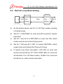
1
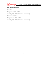
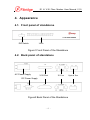
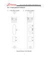
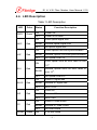
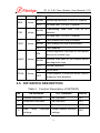
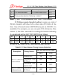
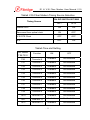
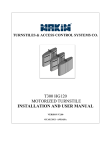
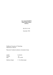
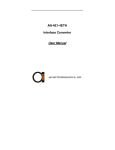
www.fibridge-tr.com [email protected] GYM Bilgi Teknolojileri E1 and V.35 Fiber Modem User Manual (Version 1.0) Beijing Fibridge Co., Ltd Table of Content 1. Overview ................................................................ 1 2. Features ................................................................. 1 3. Specification.......................................................... 2 3.1. 3.2. 3.3. 3.4. 3.5. 3.6. E1 interface ............................................................. 2 Optical interface ...................................................... 3 V.35 Interface .......................................................... 3 Size ......................................................................... 4 Power ...................................................................... 4 Environment ............................................................ 5 4. Appearance............................................................ 6 4.1. 4.2. 4.3. 4.4. 4.5. Front panel of standalone........................................ 6 Back panel of standalone ........................................ 6 Front panel of chassis ............................................. 7 LED Description ...................................................... 8 DIP SWITCH DESCRIPTION.................................. 9 5. Typical Application.............................................. 13 5.1. 5.2. Peer to Peer .......................................................... 13 Star Topology ........................................................ 14 6. Diagnosis and Maintenance ............................... 14 6.1. 6.2. 6.3. Local Loop Back Setting ....................................... 14 Diagnostic Loop Back Setting ............................... 15 Remote Loop Back Setting.................................... 16 7. Order Information................................................ 17 7.1. 7.2. Model .................................................................... 17 Part Number (P/N) ................................................ 17 E1 & V.35 Fiber Modem User Manual V1.0 1. Overview E1 Fiber Modem or V.35 Fiber Modem can convert G.703 E1 signal or V.35 signal to single-mode or multimode fiber which extend the transmitting distance greatly. E1 signal support framed and unframed mode. When in framed mode, continuous or discontinuous time-slot can be selected. E1 fiber modem and V.35 fiber modem can work together. Both of them are widely used in extending user interface in ATM or DDN. 2. Features z Fully compatible with ITU-T, G.703, G.704, G.823, V.35 recommendation z Standalone and module available, support hot-swap z Framed (N*64Kbps) and unframed (2.048Mbps) optional z Frame mode support PCM30/ PCM31 z CRC/non-CRC auto-negotiation on E1 interface z Support internal clock, E1 recovery clock, optical line clock or V.35 line clock z Provide local loop back test, functional diagnostic loop back test and remote loop back test z For V.35 interface, at receive side, clock is reversed and - 1 - E1 & V.35 Fiber Modem User Manual V1.0 non-reversed auto-negotiation, while at transmission side, clock can be configured as reversed or non-reversed z For E1 interface, 75 ohm (unbalanced) and 120 ohm (balanced) available and auto-negotiation z Comprehensive LED indicators on front panel, convenient for the diagnosis of equipment working state z -48VDC or 220VAC power supply selectable z 16-slot, 4U-height elaborate cooling design and two redundant power supply chassis available 3. Specification 3.1. E1 interface z Compliant with G.703, G.704 z Code type: HDB3 z Data rate: 2.048Mbps or n*64Kbps, n=1~31 z Line impedance: 75Ω(Unbalanced) / 120Ω(Balanced) z Interface connector: BNC(75Ω) / RJ45(120Ω) z Jitter performance: Compliant with ITU-T G.742 and G.823 z Frame mode: Framed / Unframed optional Definition of RJ45 connector(120Ω E1 balanced): PIN 1 2 4 5 3,6 Others Definition RX+ RX- TX- TX+ GND Reserved - 2 - E1 & V.35 Fiber Modem User Manual V1.0 3.2. Optical interface z Line code type: 1B1C z Bit rate: 4.096Mbps z Wavelength: MM 850/1310nm optional, SM 1310/1550nm optional z Connector: FC/SC/ST optional z Transmission distance: MM: 0~2Km, SM: 0~120Km 3.3. V.35 Interface z Data rate: 2.048Mbps or n*64Kbps, n=1~31 z Jitter performance: Compliant with ITU-T V.35 standard z Connector: DB25 female jack z Operation mode: DTE/DCE optional Definition of V.35 interface (DB25 pins) No. Definition Description 1 GND Ground 2 TDA Transmit data line A 3 RDA Receive data line A 4 RTS DTE ask for transmitting data 5 CTS DCE clear the transmitting 6 DSR DCE ask for transmitting data 7 GND Ground - 3 - E1 & V.35 Fiber Modem User Manual V1.0 8 DCD DCE transmit carrier wave signal 9 RCB Receive clock line B 11 XTCB DTE transmit clock B 12 TCB Transmit clock line B 14 TDB Transmit data line B 15 TCA Transmit clock line A 16 RDB Receive data line B 17 RCA Receive clock line A 20 DTR DTE Prepare for receiving data 24 XTCA DTE transmit clock A Others, N.A. 3.4. Size Standalone: 252 (Width)×136 (Depth)×36 (Height) Module: 220 (Length)×176(Width)×25.3(Height) 16-slot chassis:441 (Width)× 340 (Depth)× 180 (Height) 3.5. Power Power supply: AC Power: 100V-240V, 0.4-0.2A, 50-60 Hz DC Power: -48V, 0.4A Power consumption <2W - 4 - E1 & V.35 Fiber Modem User Manual V1.0 3.6. Environment Operation Temperature: 0℃~50℃; Humidity: 0%~90%(25℃, non-condensed); Transport and store Temperature: -20℃~60℃; Humidity: 0%~90%(25℃, non-condensed); - 5 - E1 & V.35 Fiber Modem User Manual V1.0 4. Appearance 4.1. Front panel of standalone DIP Switch LEDs Figure1 Front Panel of the Standalone 4.2. Back panel of standalone AC Power Supply V.35 Port E1 Port DC Power Supply 图 2 光猫设备后面板图 Figure2 Back Panel of the Standalone - 6 - Optical Port E1 & V.35 Fiber Modem User Manual V1.0 4.3. Front panel of chassis V.35 Fiber modem E1 Fiber modem Figure3 Panel of the Module - 7 - E1 & V.35 Fiber Modem User Manual V1.0 4.4. LED Description Table 1 LED Description LED Color PWR Green NOP LOF Red Red Status ON Power OK OFF Power off or failed ON Local optical signal loss BLINK Remote optical signal loss OFF No optical signal loss ON Local Optical Line lose synchronization BLINK Remote Optical Line lose synchronization OFF No Optical Line LOF ON IE-6 ELOS AIS CV VLINK Red Red Red Red Green Function Description BLINK Local optical line’s bit error rates is over 10-6. Remote optical line’s bit error rates is over 10-6. OFF No Optical Line IE-6 ON Local E1 signal loss BLINK Remote E1 signal loss OFF No E1 LOS ON Local AIS BLINK Remote AIS OFF No E1 AIS ON Local E1 code invalid BLINK Remote E1 code invalid OFF No code invalid ON V.35 port linked - 8 - E1 & V.35 Fiber Modem User Manual V1.0 RXD OFF V.35 port not linked BLINK Receiving data from V.35 or E1 channel OFF No data from V.35 or E1 channel Yellow BLINK TXD Yellow TEST Yellow PTOK Yellow channel OFF No data from V.35 or E1 channel ON Test enabled and loop successful BLINK Test enabled but loop unsuccessful OFF Test disabled Local/Diagnostic loop back or the remote ON LOOP Transmitting data from V.35 or E1 device set remote loop BLINK Remote loop back or the remote device set diagnostic loop OFF Normal operation ON No bit error Yellow OFF If test enabled, it means bit errors, and no meaning if test disabled. 4.5. DIP SWITCH DESCRIPTION Table 2 Bit Function Description of SET/SW5 ON Definition OFF Definition Default 1 Remote loop back No loop back OFF 2 Diagnostic loop back No loop back OFF 3 Local loop back No loop back OFF 4 Use settings local time-slot Follow remote time-slot settings - 9 - OFF E1 & V.35 Fiber Modem User Manual V1.0 5 Bit error test Normal operation OFF 6 V.35 clock NORMAL V.35 clock RESERVED OFF 7 OFF Timing mode selection. Referring to table 3 8 OFF Note: 1) “SET” is for standalone, and “SW5” is for module. 2) ‘Follow remote timeslot setting’ means one side of F4-56’s timeslot will follow to the other side of F4-56’s all the time. Only in framed mode & Bit7 Bit8 being set as ON OFF, it is available. For example, you use one pair of F4-56 device. One named A, the other named B. For setting B’s timeslot following A, you should set the ‘SET’ DIP SWITCH as follows: Bit 1 2 3 4 5 6 7 8 A OFF OFF OFF OFF OFF X1 ON OFF B OFF OFF OFF X2 OFF X1 ON ON X1 lies on the router, for X2, both ON and OFF are OK. Table3 E1 Fiber Modem Timing Source Selection ON DIP SWITCH SET/SW5 Description Timing Source Internal OSC For E1 used in Framed Mode Recovered from E1 Clock Recovered from optical clock For E1 used in Recovered unframed mode E1 Clock from - 10 - BIT7 BIT8 ON ON OFF ON ON OFF OFF OFF E1 & V.35 Fiber Modem User Manual V1.0 Table4 V.35 Fiber Modem Timing Source Selection ON DIP SWITCH SET/SW5 Timing Source BIT7 BIT8 Internal OSC. ON ON Recovered from optical clock ON OFF V.35 DTE Clock OFF OFF N.A. OFF ON Table5 Time-slot Setting DIP Switch Function ON OFF TS0 Time-slot 0 Available Not Available TS1 Time-slot 1 Available Not Available TS2 Time-slot 2 Available Not Available TS3 Time-slot 3 Available Not Available TS4 Time-slot 4 Available Not Available TS5 Time-slot 5 Available Not Available TS6 Time-slot 6 Available Not Available TS7 Time-slot 7 Available Not Available TS8 Time-slot 8 Available Not Available TS9 Time-slot 9 Available Not Available TS10 Time-slot 10 Available Not Available TS11 Time-slot 11 Available Not Available TS12 Time-slot 12 Available Not Available TS0-TS31 - 11 - E1 & V.35 Fiber Modem User Manual V1.0 TS13 Time-slot 13 Available Not Available TS14 Time-slot 14 Available Not Available TS15 Time-slot 15 Available Not Available TS16 Time-slot 16 Available Not Available TS17 Time-slot 17 Available Not Available TS18 Time-slot 18 Available Not Available TS19 Time-slot 19 Available Not Available TS20 Time-slot 20 Available Not Available TS21 Time-slot 21 Available Not Available TS22 Time-slot 22 Available Not Available TS23 Time-slot 23 Available Not Available TS24 Time-slot 24 Available Not Available TS25 Time-slot 25 Available Not Available TS26 Time-slot 26 Available Not Available TS27 Time-slot 27 Available Not Available TS28 Time-slot 28 Available Not Available TS29 Time-slot 29 Available Not Available TS30 Time-slot 30 Available Not Available TS31 Time-slot 31 Available Not Available Notice: a) If you want to make the converter work under unframed mode, you should set TS0 to TS31 all to ON or OFF. b) Under framed PCM30 mode, TS16 of E1 channel is used to carry command instead of payload. TS0 and TS16 should be set OFF, and the most bandwidth is 1920Kbps. - 12 - E1 & V.35 Fiber Modem User Manual V1.0 5. Typical Application 5.1. Peer to Peer E1 modem used in pairs E1 V.35 modem used in pairs Fiber V.35 Router DDN/ATM E1 Modem E1 Modem DDN/ATM E1 Fiber V.35 Modem V.35 V.35 Modem Router E1 modem &V.35 modem used together In the above application, it is recommended that user select router’s timing signal as unique timing source, and makes all the other equipment follow this timing source. - 13 - E1 & V.35 Fiber Modem User Manual V1.0 5.2. Star Topology E1 or V.35 Cable Fiber Router E1 or V.35 Fiber Modem 16-slot Converter Chassis Fiber E1 or V.35 Cable Router E1 or V.35 Fiber Modem User End 6. Diagnosis and Maintenance 6.1. Local Loop Back Setting a) Set bit 3 of SET/SW5 ON, then the E1 or V.35 fiber modem is forced to under local loop back test mode. b) Or, connect the TX and RX of optical port with a fiber cable. E1orV.35 E1/V.35 Fiber Modem E1/V.35 Tester - 14 - Fiber E1 & V.35 Fiber Modem User Manual V1.0 c) Connect E1 or V.35 port on fiber modem to a Router or a Transmission Analyzer, as picture above. d) If local loop back successful, all red LEDs on the converter should be off, and TXD & RXD LEDs should blink. 6.2. Diagnostic Loop Back Setting E1orV.35 E1/V.35 Fiber E1orV.35 Fiber Modem Fiber E1/V.35 Modem E1/V.35 Tester a) As the picture above, set E1 or V.35 fiber modem working in framed mode. b) Set bit 2 of SET/SW5 on remote end ON to perform diagnostic loop back. c) Set bit 7 and bit 8 of SET/SW5 on remote end ON, which means remote end is the timing source. d) Set bit 7 ON and bit 8 OFF of local SET/SW5, which means local end follows the Fiber port timing. e) If diagnostic loop back successful, LOS LED on local and remote end should be off, TXD & RXD LEDs on local end should blink. For V.35 fiber modem, VLINK of on local end should be on, under diagnostic loop back. - 15 - E1 & V.35 Fiber Modem User Manual V1.0 6.3. Remote Loop Back Setting E1orV.35 E1orV.35 E1/V.35 Fiber Fiber Modem Fiber E1/V.35 Modem E1/V.35 Tester a) As the picture above, set E1 or V.35 fiber modem working in framed mode. b) Set bit 1 of SET/SW5 on local end ON to perform remote loop back. c) Set bit 7 and bit 8 of SET/SW5 on local end ON, which means remote end is the timing source. d) Set bit 7 ON and bit 8 OFF of remote SET/SW5, which means local end follows the Fiber port timing. e) If remote loop back successful, LOS LED on local and remote end should be off, TXD & RXD LEDs on local end should blink. For V.35 fiber modem, VLINK of on local end should be on, under remote loop back. - 16 - E1 & V.35 Fiber Modem User Manual V1.0 7. Order Information 7.1. Model F9-480 E1 Optical Multiplexer For more detailed order information, please check the Part Number. 7.2. Part Number (P/N) F9-E1abbcde E1 Fiber Modem F9-V35abbcde V.35 Fiber Modem F9-E1V35abbcde FC-416 E1&V.35 Modem , E1 interface & V.35 interface optional 16-slot Protocol converter chassis, with SNMP management abbcd represents fiber parameter separately as follows: a: Optical port type S: Single mode, M: Multimode, W: Single strand bb: Optical port transmission distance 02:20Km, 04:40Km, 06:60Km, 08: 80Km, 10: 100Km, 12: 120Km c: Wavelength - 17 - E1 & V.35 Fiber Modem User Manual V1.0 1: 850nm, 2:1310nm,3:1550nm d: Connector type F: FC, C: SC, T: ST e: Power input type A: 220VAC, D: -48VDC ** We Reserve the right to vary descriptions and specifications without notice due to Fibridge’s policy of continuous product improvement** - 18 -