1
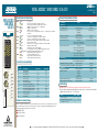
JOBAID
®
TOTAL ACCESS 3000 SHDSL V.35 LTU
TOTAL ACCESS
3000 SHDSL
V.35 LTU
FRONT PANEL LED INDICATORS
●
●
●
SHDSL ●
●
●
G.703 ●
PWR
●
Nx64k ●
●
RTS
●
●
RLSD ●
●
TST
●
●
✷
●
ALM ●
●
●
SHDSL
1182008L5
N
x
6
4
K
DEFAULT PROVISIONING OPTIONS
Off
Green
Yellow
Off
Green
Red
Off
No power
Self-test passed and the module is In Service
Self-test passed and the module is Out of Service
SHDSL Loop is Out of Service -- Unassigned
SHDSL Loop is trained
SHDSL Loop is not trained
G.703 port is not configured, Out of Service -- Unassigned, or in alarm
condition
Green
G.703 port configured and no alarms
Off
Service is not configured or in alarm condition
Green
Service is configured and operating normally
Off
Nx64k service not configured or RTS control line is OFF
Green
RTS control line is ON
Off
Nx64k service not configured or RLSD control line is OFF
Green
RLSD control line is ON
Off
Module is not in loopback or BERT
Green
Local loopback is active, or BERT running with no errors
Blinking Yellow Module is running a BERT with bit errors
Red
BERT running with no pattern sync
Off
No alarm condition detected
Yellow
Remote alarm condition detected
Red
Alarm condition detected locally
V.35 PORT PIN ASSIGNMENTS
V.35 Port
RX
PWR
SHDSL
G.703
G.703
Nx64K
TX
RTS
RLSD
TST
ALM
Circuit No.
102
103
104
105
106
107
108/2
109
113
114
115
140
141
142
Circuit Name
To/From DCE
Signal Ground
Transmit Data
To
Receive Data
From
Request To Send
To
Clear To Send
From
Data Set Ready
From
Data Terminal Ready
To
Received Line Signal Detect
From
Transmit Signal Element Timing
To
Transmit Signal Element Timing
From
Receive Signal Element Timing
From
Remote Loopback
To
Local Loopback
To
Test Indicator
From
61182008L5-22A
0202
Pinout (A/B)
B
P/S
R/T
C
D
E
H
F
U/W
Y/AA
V/X
N
L
NN
INTERFACE CONNECTIONS
Provisioning
Unit Options
Cross-Connect Map
Local Management
LT Mode Clk Source
NTU Auto Provisioning
External Port Alarms
Line Card Service State
G.703 Port Service State
Nx64K Port Service State
Options
Disabled, Enabled
Internal Clock
Nx64 ETC
G.703 RX Clock
Disabled, Enabled
Disabled, Enabled
In Service
Out of Service - Maintenance
Out of Service - Unassigned
In Service
Out of Service - Maintenance
Out of Service - Unassigned
In Service
Out of Service - Maintenance
Out of Service - Unassigned
SHDSL Options
Rate (Kbps)
Enter a new value for N from 3 to 36,
where Rate(Kbps)=(N x 64) + 8:
SNR Margin Alarm Threshold(dB)
Disabled, Enabled
Loop Attenuation Alarm Threshold (dB) Disabled, Enabled
Test Options
Loopback Timeout(Min)
Disabled, Enabled
BERT Test Pattern
All Zeros
All Ones
2e15-1
2e23-1 2e15-1
BERT Test Pattern Polarity
Normal, Inverted
Nx64K In-band Pattern Detection
Disabled, Enabled
All Idle
Enabled
Internal Clock
Disabled
Enabled
Out of Service - Unassigned
Out of Service - Unassigned
Out of Service - Unassigned
2056 (N=32)
Disabled
Disabled
Disabled
2e15-1
Normal
Disabled
COMPLIANCE
Caution: Up to -200 VDC may be present on telecommunications wiring.
This product is intended for installation in restricted access locations only and in
equipment with a Type “B” or “E” enclosure.
Code
Power Code (PC)
Telecommunication Code (TC)
Installation Code (IC)
Input
F
–
A
Output
C
X
–
The G.703 signal is transmitted to the network either via the Total Access 3000 backplane connectors or
the two BNC connectors mounted on the faceplate. The G.703 signal and the SHDSL signal use the
following backplane amphenol connector Pairs:
■ SHDSL - Pair 2
■ G.703 Tx - Pair 8
■ G.703 Rx- Pair 7
C A U T I O N !
SUBJECT TO ELECTROSTATIC DAMAGE
OR DECREASE IN RELIABILITY.
HANDLING PRECAUTIONS REQUIRED.
Default
■ For a complete Installation and Maintenance faxback: (877) 457-5007, Document #766. Please have your fax number available. ■
PRICING AND AVAILABILITY 800.827.0807
TECHNICAL SUPPORT 800.726.8663
RETURN FOR REPAIR 256.963.8722
www.adtran.com
61182008L5-22A
TOTAL ACCESS 3000 SHDSL V.35 LTU MENU TREE
SHDSL MENU OPTIONS
The Total Access 3000 SHDSL V.35 Menus can be provisioned only through the Total Access 3000 System Controller Unit (SCU), P/N 1181018L1. These options are accessed via the local terminal or remote access via the 10BaseT or TL1
interfaces. Connect a terminal emulator via the RS-232 (DB-9) connector on the faceplate of the SCU. The terminal must be VT100 or compatible and set for 9600 bps, 8 data bits, no parity, 1 stop bit. At the LOGIN screen, enter the
account name and system password. Select ACCESS MODULES from the Total Access Menu. Access the desired SHDSL module by selecting the corresponding slot number.
SHDSL V.35 LTU
Main
Menu
1. LTU
1. Unit Information
2. NTU
1. Cross-Connect Map
2. Restore Factory Defaults
1. Unit Options
3. Local Management
4. LT Mode Clk Source
5. Circuit ID
6. Software Update
7. Change Password
SHDSL Version
Vendor List Number
Vendor Issue Number
Vendor Software Version
Unit Identification Code (CLEI)
Vendor ID
Vendor Model Number
Vendor Serial Number
Other Vendor Information
SHDSL Version
Vendor List Number
Vendor Issue Number
Vendor Software Version
Unit Identification Code (CLEI)
Vendor ID
Vendor Model Number
Vendor Serial Number
Manufacture Date
PROM Checksum
8. NTU Auto Provisioning
9. Line Card Service State
10. G.703 Port Service State
11. External Port Alarms
1. Local
2. Provisioning
12. Nx64K Port Service State
2. Remote
1. Rate (kbps)
2. SHDSL Options
2. SNR Margin Alarm Threshold (dB)
3. Loop Attenuation Alarm Threshold (dB)
3. G.703 Options
1. Tx Clock Source
2. Tx Clock Polarity
4. Nx64K Options
3. RTS (Circuit 105)
4. CTS (Circuit 106)
5. RTS to CTS Delay (ms)
6. DSR (Circuit 107)
5. Test Options
7. DTR (Circuit 108/2)
3. Status
1. LTU SHDSL Port
8. RLSD (Circuit 109)
2. LTU G.703 Port
2. G.704 CRC-4 Multiframing
3. G.704 Idle Pattern
4. Customer Spare Bits Insertion
5. Customer Spare Bits Pattern
6. Network Spare Bits Insertion
4. NTU SHDSL Port
2. BERT Test Pattern Polarity
7. Network Spare Bits Pattern
1. SHDSL Local Loopback
2. SHDSL Remote Loopback
4. Nx64K Inband Pattern Detection
5. RL (Circuit 140)
3. SHDSL BERT
6. LL (Circuit 141)
4. G.703 Local Loopback
7. TI (Circuit 142)
5. G.703 BERT
6. Nx64K Local Loopback
7. Nx64K BERT
5. Performance History
6. Terminal Mode
1. Dual Sided
2. Custom Transparent
3. Customer Non-Transparent
1. LTU SHDSL
4. Network Transparent
2. LTU G.703
5. Network Non-Transparent
3. SHDSL PM Thresholds
6. Off
12/27/01 10:20
1. ISDN-PRA V3
1. Loopback Timeout (Min)
3. BERT Test Pattern Polarity
Total Access System
Local Cross-Connect Map
SHDSL Timeslots
G.703 Timeslots
TS12 = 0
TS24 = 0
TS0 = 0
TS12 =
TS24 =
TS0 = 0
TS1 = 0
TS13 = 0
TS25 = 0
TS1 = 0
TS13 =
TS25 =
TS2 = 0
TS14 = 0
TS26 = 0
TS2 = 0
TS14 =
TS26 =
TS3 = 0
TS15 =
TS27 =
TS15 = 0
TS27 = 0
TS3 = 0
TS4 = 0
TS16 = 0
TS28 = 0
TS4 = 0
TS16 =
TS28 =
TS17 = 0
TS29 = 0
TS5 = 0
TS17 =
TS29 =
TS5 = 0
TS6 = 0
TS18 = 0
TS30 = 0
TS6 = 0
TS18 =
TS30 =
TS7 = 0
TS19 = 0
TS31 = 0
TS7 = 0
TS19 =
TS31 =
TS20 = 0
TS32 = N/A
TS8 =
TS20 =
TS8 = 0
TS9 = 0
TS21 = 0
TS33 = N/A
TS9 =
TS21 =
TS10 = 0
TS22 = 0
TS34 = N/A
TS10 =
TS22 =
TS11 = 0
TS23 = 0
TS35 = N/A
TS11 =
TS23 =
Timeslot Assignments
Commands
A. Apply New Map
G. Full G.703 Service
0. Idle
1. G.703
C. Cancel Changes
Tab. Select SHDSL or G.703 Timeslots
32. G.704 Frame
33. Nx64K
Movement Keys: U. Up D. Down L. Left R. Right
G.704 Framing =
3. NTU Nx64k Port
RAM/ROM Power-on Self Test
4. Test
Shelf:
Slot: 15
Unacknowledged Alarms: None
Circuit ID:
8. Network RAI Generation
9. Network E-bit Generation
General Status
Aggregate Rate (kbps)
SNR Margin (dB) (Cur/Min/Max)
Loop Attenuation (dB) (Cur/Min/Max)
Errored Seconds (ES)
Severely Errored Seconds (SES)
Unavailable Seconds (UAS)
Code Violations Count (CVC)
LOSW Seconds (LOSWS)
Loopback Status
BERT Status
Alarms
WARRANTY
Warranty for Carrier Networks products manufactured by ADTRAN and supplied under Buyer’s order for international use is five (5) years. For a complete copy of ADTRAN’s International Equipment Warranty, document number
60000003#I-3: (877) 457-5007, Document #583.