1
People to People Technology
MICROLINE
3390/3391
IBM-/EPSON-compatible
User Manual
Accessories
Roll Paper Stand (narrow version only)
Bottom Tractor (narrow, wide version),
Tractor feet
Cut Sheet Feeder, CSF
(1-Bin, 2-Bin; narrow, wide version)
Pull Tractor (narrow, wide version)
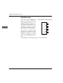
Serial Interfaces Cards:
RS-232C, RS-232C / Current Loop,
RS-422A
I
II
Legal note
The information contained in this manual is as complete, accurate
and up-to-date as possible. Provided legally permissible, we shall
accept no liability for consequential damage in connection with the
use of this manual. Otherwise, we shall only be liable for intent or
gross negligence. We make no guarantee that alterations to the software programs and devices of other manufacturers referred to in
this manual will not affect the usability of the information contained in this manual.
The author reserves all rights. The manual may not be duplicated
completely or in part in whatever form without the consent of the
author.
The content of this manual is subject to alteration without notice.
Please also read the information following the table of contents.
III
Guidance through the manual
The first part of this manual is directed largely at users who have no
or very little technical knowledge. Experienced users, suppliers
and technicians will find additional technical information in the
"Programming" part and in the appendices.
There are three ways of accessing the information in this manual:
IV
●
You can read the text in the order in which the manual is
arranged.
●
You can find the passages you are looking for under the headings below or the table of contents.
●
The index in appendix F will guide you to the passages in the
manual relating to specific printer terms and messages.
Assembling, Setting Up
Chapter 1, 2
Programming
Chapter 10 - 17
Daily Printer Operation
Chapter 3 - 6
Technical Data
Appendix A - D
Accessories
Chapter 7
Paper Formats
Appendix E
Troubleshooting
Chapter 8
Short Reference
Appendix H
Operation
Programming
Chapter 1:
Assembling and setting up the printer
1
Chapter 2:
A guided tour of the printer
2
Chapter 3:
Paper handling
3
Chapter 4:
Printer menu settings
4
Chapter 5:
Printer control
5
Chapter 6:
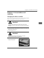
Consumables and cleaning
6
Chapter 7:
Accessories
7
Chapter 8:
Troubleshooting
8
Chapter 9:
Packing the printer for transportation
9
Chapter 10: IBM - Standard functions
10
Chapter 11: IBM - Graphics
11
Chapter 12: IBM - Control code tables
12
Chapter 13: IBM - Characters sets
13
Chapter 14: Epson - Standard functions
14
Chapter 15: Epson - Graphics
15
Chapter 16: Epson - Control code tables
16
Chapter 17: Epson - Characters sets
17
V
VI
Appendices
Appendix A: Technical Data
A
Appendix B: Code pages
B
Appendix C: Bar codes
C
Appendix D: Interface data
D
Appendix E: Paper formats and printing areas
E
Appendix F: Index / Glossary
F
Appendix G: Trademarks
G
Appendix H: Short reference
H
VII
Table of contents
VIII
III
IV
XV
XVI
XVII
XVIII
XVIII
XIX
XIX
Legal note
Guidance through the manual
Safety advice
Servicing / maintenance
Advice and warning symbols
Meaning of text styles in the manual
Consumables / accessories
Machine-readable fonts
Further information
Chapter 1:
1-1
1-1
1-2
1-2
1-2
1-3
1-3
1-4
1-5
1-5
1-6
1-7
1-7
1-8
1-8
1-9
1-10
1-11
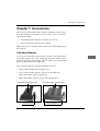
Assembling and setting up
Unpacking the printer
Checking the items supplied
Assembling the printer
Location
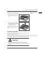
Power supply
Setting up the printer
Removing the transport packing
Inserting the ribbon cassette
The paper support
Fitting the paper support
Raising the paper support
Removing the paper support
The paper separator
Removing the paper separator
Fitting the paper separator
Connecting the printer to the computer
Connecting the printer to the power supply
Emulation / printer drivers
Chapter 2:
2-1
2-1
2-2
2-3
2-4
2-4
2-5
...
A guided tour of the printer
The printer and its components
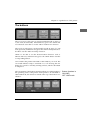
Front view
Inside view
Rear view
The operator panel
The indicator lamps
The buttons
2-5
2-7
2-7
2-8
2-8
2-9
Button functions in ON LINE / OFF LINE mode
Button functions in menu mode
Print functions
PRINT QUALITY
CHARACTER PITCH
RESET
Chapter 3:
3-1
3-2
3-2
3-2
3-3
3-7
3-8
3-8
3-11
3-11
3-11
3-11
3-13
3-13
3-14
3-15
3-16
3-16
Paper handling
Notes on paper types
Paper lever
Adjusting for the paper thickness
Print head lever
Adjusting the print head gap
Paper feed: cut sheets
Paper feed: continuous paper
Feeding continuous paper from the rear
Feeding continuous paper from the bottom
Switching between continuous paper and cut sheets
From continuous paper to cut sheets
From cut sheets to continuous paper
Setting Top of Form
Changing Top of Form
Indicating or changing print position
Automatic advance to Form Tear-Off position
Checking Top of Form
Changing the Tear-Off position
Chapter 4:
4-1
4-1
4-1
4-2
4-3
4-4
4-9
4-9
4-9
4-9
4-10
4-11
4-14
4-14
Printer menu settings
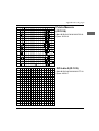
The printer menu
Activate menu mode
Print menu settings
Changing the menu settings
End menu mode
Layout of the printer menu
Explanation of menu items
Printer Control
Font
Symbol Sets
Rear Feed, Bottom Feed, Top Feed
Set-Up
Parallel I/F
Serial I/F
IX
Chapter 5:
5-1
5-1
5-3
5-3
5-5
5-6
Printer Control
Emulation
Printer drivers
Characters and control characters
Printing under DOS
Printing under DOS with serial interface
Troubleshooting
Chapter 6:
6-1
6-2
6-3
Consumables and cleaning
Changing the ribbon cassette
Inserting a new ribbon cassette
Cleaning
Chapter 7:
7-1
7-2
7-2
7-3
7-5
7-7
7-8
7-9
7-10
7-10
7-10
7-10
Accessories
Cut sheet feeder
Checking the items supplied
Adjusting the length of the feed rail
Installing the feed rail
Installing the cut sheet feeder
Paper feed
Automatic paper feed
Manual paper feed
Feeding of cut sheets and continuous paper
Print area
Selecting the paper tray
Removing the cut sheet feeder
from the printer
Adjusting the mounting bracket
The pull tractor
Checking the items supplied
Installation
Feeding continuous paper
Removing the tractor feed
The bottom tractor
Checking the items supplied
Fitting the bottom tractor feet
Installing the tractor feet
Feeding continuous paper
Changing between formats of
continuous paper formats
7-11
7-12
7-12
7-13
7-15
7-17
7-18
7-18
7-18
7-20
7-22
7-24
...
X
7-25
7-25
7-25
7-26
7-28
7-28
The roll paper stand
Checking the items supplied
Installation
Paper feed
Interface cards
Installation
Chapter 8:
8-1
8-4
8-6
8-7
Troubleshooting
Possible faults
Fault tables
Major faults
Testing options
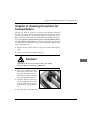
Chapter 9:
Packing the printer for transportation
Chapter 10:
10-1
10-3
10-6
10-7
10-10
10-12
10-16
10-18
10-18
10-20
10-21
10-26
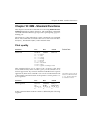
IBM - Standard Functions
Print quality
Print modes
Print attributes
Multifunction commands
Tabulators
Positioning
Page formatting
Line spacing
Paper feed
Control of the Cut Sheet Feeder
Character sets
Other commands
Chapter 11:
11-1
11-4
11-6
11-8
11-8
11-10
11-15
IBM - Graphics
Bit image graphics
Graphics of high resolution
Programming graphics
Graphics of low resolution
Graphics densities
Aspect ratio
Print alignment
Chapter 12:
IBM - Control Code Tables
XI
XII
Chapter 13:
13-1
13-1
13-2
IBM - Character Sets
IBM Character Sets
National Character Sets
Code Pages
Chapter 14:
14-1
14-2
14-6
14-8
14-9
14-12
14-15
14-17
14-18
14-19
14-20
14-22
14-27
14-27
14-31
14-33
14-35
14-41
Epson - Standard Functions
Print quality
Print modes
Print attributes
Multifunction commands
Tabulators
Positioning
Page formatting
Line spacing
Paper feed
Control of Cut Sheet Feeder
Character Sets
Other commands
Additional ESC/P2 commands
Step size and character spacing
Vertical print position
Print area
Select font
Character sets and code pages
Chapter15:
15-1
15-4
15-5
15-8
15-9
15-11
15-12
15-15
15-17
15-17
Epson - Graphics and downloadable characters
Bit image graphics
Graphics of high resolution
Programming graphics
Graphics of low resolution
Programming graphics
Print alignment
Downloadable characters
Generate downloadable characters
Additional ESC/P2 commands
Raster graphics
Chapter 16:
Epson - Control Code Tables
Chapter 17:
17-1
17-1
17-2
Epson - Character Sets
Epson Character Sets
National Character Sets
Code Pages
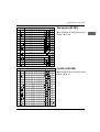
Appendix A: Technical Data
Appendix B:
B-1
B-2
B-3
Code Pages
Overview
Conversion table
Code pages
Appendix C:
C-2
C-2
C-3
C-8
C-17
C-18
C-20
Bar Codes
Bar code types
Positioning
Selection of type and size of Bar code
Printing of a 24 pin Bar code
Examples
Zip Code
Setting the print position
Appendix D:
D-1
D-2
D-3
D-4
D-4
D-5
D-6
D-7
D-8
D-10
D-11
D-12
D-13
D-14
D-15
D-16
D-17
D-21
...
Interface Data
Parallel Interfacing (Centronics)
Pin Description
Signal levels
Timing
Interface test
RS-232C Serial Interface
Pin Description
Signal levels
Interface wiring
Interface test
RS-422A Serial Interface
Pin Description
Signal levels
Menu options of serial interfaces
Transmission protocols
Connections of the RS-422A Interface
Diagrams
Interface test
XIII
D-22
D-22
D-23
D-24
D-26
D-29
D-30
D-37
Coresident RS-232C/Current Loop Interface
Technical Data
Pin description
Interface selection
Transmission protocols
Connections of the Current Loop Interface
Diagrams
Interface test
Appendix E:
E-1
E-1
E-2
E-2
E-2
E-4
E-4
E-4
E-5
E-5
E-6
E-6
E-6
E-6
E-7
E-7
E-7
Paper formats and print areas
Continuous paper
Format
Weight
Thickness
Perforation
Further information
Cut sheet paper
Format
Weight
Labels (on single sheet)
Format
Weight
Further information
Labels (on continuous paper)
Format
Weight
Further information
Appendix F: Index / Glossary
Appendix G: Trademarks
Appendix H: Short reference
XIV
Safety advice
Your printer has been developed with the utmost care to ensure
safe, reliable operation over many years. Like all electrical devices,
there are a few basic precautions you need to observe. These precautions are necessary in the first instance for your own safety but
also protect the printer against any damage. Please read through
the manual carefully and keep it handy.
Make sure...
●
the printer is standing on a stable, flat surface. To prevent overheating, there should be free space all around the printer; openings should not be covered. Never place the printer directly next
to a radiator or the air outlet of an air-conditioning system. Do
not expose the printer to direct sunlight;
●
the printer does not come into direct contact with liquids.
●
no objects are pushed into the ventilation slots of the printer as
you run the risk of an electrical shock or could cause a fire;
●
you only perform the routine maintenance on the printer described in the manual. Opening the case can result in an electrical shock or other harm. Make sure you always remove the plug
from the mains socket before opening the printer case. Do not
alter the printer in any way not described in the manual - this
may cause damage to the printer and result in repairs for which
you will be liable.
Setting up the
printer
Like all electronic devices, the printer can be damaged by electrostatic charges. Static charges can form when walking on unsuitable
floor coverings, for example, and are then transferred to the device
by touching the case. Bear this in mind when choosing the location
for the printer.
XV
Power supply
Cable wiring
Ensure yourself ...
●
that the ratings of the power supply match the ratings shown on
the back of the printer. If in doubt, ask your supplier;
●
that the printer is connected to an earthed mains socket with the
cable supplied;
●
when using an extension cable or multiple socket that you do
not exceed the maximum electrical load for this;
●
all reasonable precautions have been taken to prevent damage
to the power cable. Do not place objects on the cable and make
sure it is routed so that nobody walks on it or trips over it;
●
that a damaged cable is replaced immediately;
●
before cleaning the printer or the case, that the power cable is
removed from the power supply. Use only a clean cloth for
cleaning. Do not use liquids or aerosol cleaners;
●
you have removed the plug from the mains outlet to ensure
complete isolation from the mains supply. The mains outlet you
are using must be located close to the printer and be easily
accessible.
The three wires of the power cable are colour coded. The earth wire
is yellow-green, the neutral wire is blue and the live current is on
the brown wire.
Servicing / maintenance
Any servicing work on the machine that goes beyond the maintenance described in the manual should be carried out by an authorised supplier. We are not liable for damage arising due to unauthorised servicing or through improper maintenance by unauthorised
personnel.
XVI
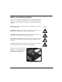
Advice and warning symbols
Observe all warnings and instructions stated on the product itself
and in the accompanying documentation. At particularly important points in the manual, warnings are marked with appropriate
symbols.
NOTE: text passages marked thus contain supplementary information or instructions.
☞
WARNING - damage: this symbol indicates a possible cause of
damage. Follow all instructions to prevent damage.
CAUTION - risk of injury: this symbol indicates a possible source
of danger. Follow all instructions to prevent injury.
CAUTION - electricity: this symbol indicates a possible source of
danger. Follow all instructions to prevent injury through an electrical shock.
CAUTION - hot: this symbol indicates a possible source of danger.
Follow all instructions to prevent injury through heat.
Should you wish to replace the
ribbon, do not touch the print
head until it has stopped moving and has cooled down.
Printhead is HOT!
XVII
Meaning of text styles in the manual
To emphasise important passages in the text or differentiate
between the meaning of a printer function and a printer message,
the following text styles or emphases are used in the manual:
●
BOLD BLOCK CAPITALS represent the display lamps of the
control panel.
●
Bold letters indicate the groups, positions and settings of the
printer menu.
●
BLOCK CAPITALS indicate the mode of the printer.
●
Italic BLOCK CAPITALS indicate the buttons of the control
panel.
●
»Brackets« highlight a printer function.
Consumables / accessories
To ensure that the printer operates perfectly and provides the
proper print quality, we recommend you use only original ribbons
or accessories supplied by us. We accept no liability for damage
resulting from the use of non-original ribbons or accessories which
would have been avoided by using original ribbons or accessories.
Original ribbons and accessories can be purchased from your
supplier.
To ensure good printing results, make sure you keep ribbons and
printing materials (paper, transparencies, etc.) for the shortest time
possible. Materials should be kept no longer than one year.
XVIII
Machine-readable fonts
The perfect readability of fonts such as OCR-A, OCR-B or bar codes
(EAN, UPC, Zip) by machines is affected by ...
●
the printing technique (resolution, edge sharpness);
●
the technical state of the printer;
●
the quality of the printing medium (toner, ink ribbon);
●
the state of the print material (glossiness, smoothness, coating,
age, reflection, surface uniformity);
●
the technical state of the reading device.
Further information
●
Leave your printer components in their packing until the manual expressly describes when and how to install them.
●
Do not fit or use the serial and parallel interface cables at the
same time.
●
Only use a clean cloth to clean the control panel and case.
●
The oiling and greasing of moving parts by the user is unnecessary.
●
If the machine is damaged, switch it off and remove the plug
from the outlet socket. Immediately arrange for it to be repaired.
●
Before contacting your supplier’s customer service department,
read the notes in Chapter 6. You may incur costs even during the
warranty period if you call on customer service when the customer is expected to remedy the fault or defect himself as
described in Chapter 6.
●
When sending off the machine, the carrier or insurer will not
accept responsibility for damage due to unsuitable packing.
XIX
Chapter 1: Assembling and setting up
Chapter 1: Assembling and setting
up
Unpacking the printer
The printer is supplied in separate parts in a cardboard box.
1. Take the printer and components out of the box.
2. Remove the packing material. Keep the original packing so that
you can transport the printer safely should the need arise later
on.
Check that the individual items supplied are complete and undamaged. Supplied with the printer are:
Narrow printer model
Checking the items
supplied
Printer parts
• Paper support
• Platen knob
• Power cable
• Ribbon cassette
• Interference filter (depending on model)
In addition, you will need a Centronics interface cable to connect
the printer to the computer. Ask your supplier for one of these.
1-1
Chapter 1: Assembling and setting up
Assembling the printer
Location
Make sure ...
• the printer is standing on a stable, flat surface. To prevent
overheating, make sure there is free space all around the
printer; openings should not be covered. Never place the
printer directly next to a radiator or the air outlet of an airconditioning system. Do not expose the printer to direct sunlight;
• the printer does not come into direct contact with liquids;
• no objects are pushed into the ventilation slots of the printer
as you run the risk of an electric shock, or other injury or
causing damage to the printer;
• you only perform routine maintenance on the printer as described in the manual. Opening the case can result in an electric shock or other harm. Make sure you always remove the
plug from the power socket before opening the case. Do not
alter the printer in any way not described in the manual as
this may cause damage to the printer and result in repairs for
which you will be liable.
Like all electrical devices, the printer can be damaged by electrostatic charges. Static charges can form when walking on unsuitable floor coverings, for example, and are then transferred to
the device by touching the case. Bear this in mind when choosing the location for the printer.
Power supply
Ensure yourself ...
• that the ratings of the power supply match the ratings shown
on the back of the printer. If in doubt, ask your supplier;
• that the printer is connected to an earthed mains socket by
means of the power cable supplied;
• when using an extension cable or multiple socket that you do
not exceed the maximum electrical load for this;
1-2
Chapter 1: Assembling and setting up
• all reasonable precautions have been taken to prevent damage
to the power cable. Do not place objects on the cable and make
sure it is routed so that nobody walks on it or trips over it;
• that a damaged cable is replaced immediately;
• you have removed the mains plug from the socket to ensure
complete isolation from the power supply. The socket provided
for this must be located close to the printer and easily accessible.
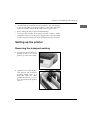
Setting up the printer
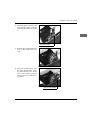
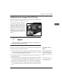
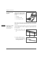
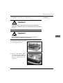
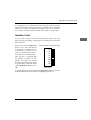
Removing the transport packing
1. If a clear protective film is attached to the cover of the
printer, you can remove this.
2. Open the cover of the printer
and remove the transport
packing. Make sure you
keep this with the other
packing material in case you
have to transport the printer
later on.
1-3
Chapter 1: Assembling and setting up
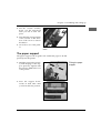
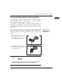
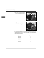
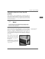
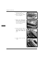
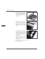
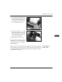
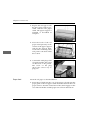
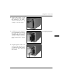
Inserting the ribbon cassette
Original ribbon cassettes are specially developed for your printer. Among other things, this concerns the ink, which contains
lubricants, and the fabric of the ribbon.
Warning!
The use of non-original ribbons can result in damage to the
print head. Use only the manufacturer's original ribbons.
A transparent ribbon guard is fitted to the front of the cassette.
Do not remove it!
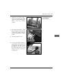
1. Take the ribbon out of the
plastic wrapping.
2. Open the printer cover
and move the print head
to the middle of the platen.
3. Place the cassette onto
the cassette holder with
the cutouts fitting onto
the pins.
Insert ribbon cassette here
1-4
Chapter 1: Assembling and setting up
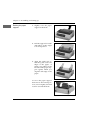
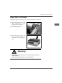
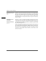
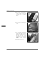
4. Tilt the cassette carefully
down over the print head
until you feel it click into
place.
5. Turn the blue transport knob
of the cassette in the direction of the arrow to tension
the ribbon.
6. Close the cover of the printer.
Tilt down the cassette and tension
ribbon
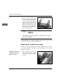
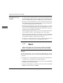
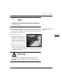
The paper support
The paper support with its guide rails enables the paper to be fed
precisely into the printer.
▲
Fitting the paper
support
▲
1. Hold the support horizontally with the pegs on the support precisely aligned with
the cutouts ( / ) in the case
of the printer.
2. Press the support downwards on both sides until
you feel it click into position.
1-5
Chapter 1: Assembling and setting up
Raising the paper
support
1. Slightly raise the paper
support at the back.
2. Pull the support forwards
and slide it at this angle
to its end position.
3. Align the guide rails so
that they just touch the
edges of the paper. A
mark is provided on the
left side of the paper support against which you
align the left edge of the
paper.
To move the paper support
back into its horizontal position, raise it slightly and fold
it down towards the back.
1-6
Chapter 1: Assembling and setting up
The paper support must be removed to fit accessories such as the
cut sheet feeder or roll paper stand.
Removing the paper
support
1. Move the paper support into
the horizontal home position.
2. Press the paper support
downwards at the back. This
will disengage it from its
catching arrangement.
The paper support must be refitted after removing the accessory.
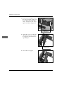
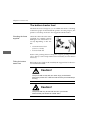
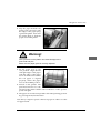
The paper separator
The paper separator prevents paper being drawn back into the
printer once it has been printed.
The paper separator has to be removed when you are using a tractor feed or cut sheet feeder (accessory). If the printer is to be used
without either of these accessories, the separator must be replaced.
The paper separator is fitted
to the printer at the factory.
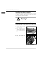
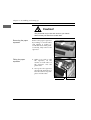
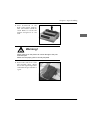
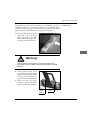
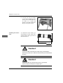
Caution!
The print head moves and can cause injury to the hands.
Switch the printer OFF LINE and wait until the print head stops
moving.
1-7
Chapter 1: Assembling and setting up
Caution!
The print head may be hot and can burn your hands.
Wait until the print head has cooled down.
Removing the paper
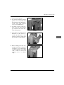
separator
Remove the paper separator
by holding it on both sides
and pulling it gently towards the front of the printer. Finally, fully remove the
separator.
Fitting the paper
separator
1. When you wish to refit
the separator, fit the
catches on both sides of
the separator onto the
platen axle.
2. Now press the separator
downwards until the you
hear the catches snap into
place on both sides.
Platen axle
1-8
Catches
Chapter 1: Assembling and setting up
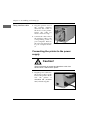
Connecting the printer to the computer
It is important to read the safety instructions on the first pages of
this manual. Before you can use the printer, you have to connect it
to your computer and to the power supply.
Your printer is supplied with a parallel Centronics interface as
standard. A serial interface can be installed as an additional facility.
This is described in Chapter 7; data on interfacing can be found in
Appendix D.
Some printer models have an interference filter supplied with
them. This square cable sleeve suppresses undesirable electromagnetic interference from other electrical sources by means of its
ferrite core.
Fitting the interference filter
(cable sleeve)
1. Open the cable sleeve of the
filter and fit it on the interface cable close to the connector at the printer end.
2. Snap the sleeve shut to close
it; the cable now has interference suppression.
☞
Note!
The parallel and serial interface cables must not be installed or
used at the same time as this may cause malfunctions.
1-9
Chapter 1: Assembling and setting up
Fitting interface cable
1. Plug the printer end of
the parallel interface
cable into the socket on
the back of the printer.
Secure the cable by
means of the two clips.
2. Connect the other end of
the interface cable to the
corresponding socket of
your computer. Refer to
the relevant instructions
in your computer manual.
Parallel interface cable
Connecting the printer to the power
supply
Caution!
There is electricity is present and therefore a risk of an
electric shock. Switch off the printer.
1. Plug the power cable into
the power socket on the
back of the printer. Make
sure the printer is
switched off (POWER
OFF) when doing this.
Power switch
1-10
Power cable
Chapter 1: Assembling and setting up
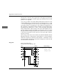
2. Plug the other end of the cable into an earthed mains outlet socket.
3. Switch on the printer and the computer by means of the respective power switches.
Your printer is now ready for operation.
Emulation / printer drivers
In the chapter "Printer drivers" you will find information on how
you can best match the emulation (language) of your printer to the
driver of your application program in order to make full use the
functions of the printer.
How to choose the emulation by means of the printer menu is described in the chapter "Printer menu settings ".
1-11
Chapter 2: A guided tour of the printer
Chapter 2: A guided tour of the
printer
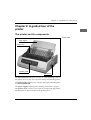
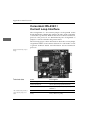
The printer and its components
Front view
paper support
printer cover
operator panel
platen knob
The operator panel indicators inform you of the operating status of
the printer. You can also use it to enter settings and test the printer.
The platen knob enables you to advance the paper when the printer is SWITCHED OFF.
The paper support enables precise feeding of cut sheets of paper.
The printer cover consists of two sections and protects the printer
mechanism from dirt and reduces the printing noise.
2-1
Chapter 2: A guided tour of the printer
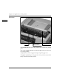
Inside view
platen
print head and
ribbon cassette
paper seperator
The print head is the part of the printer that contains the printing
pins.
The original ribbon cassette contains the high-quality ink necessary
for perfect printing.
The platen advances the paper during the printing process.
The paper separator prevents paper that has just been ejected from
being drawn back into the printer.
2-2
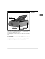
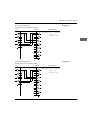
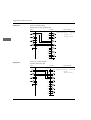
Chapter 2: A guided tour of the printer
Centronics-interface
Rear view
paper lever
power switch
socket panel
power socket
The printer and computer are connected by means of the interface
socket. The parallel Centronics interface or a serial interface (accessory) are provided for this purpose.
The socket panel must be broken out in order to fit a serial interface.
Power is supplied to the printer by plugging the power cable into
the power socket.
The printer is switched on or off by means of the power switch.
The paper feed is adjusted by means of the paper lever.
2-3
Chapter 2: A guided tour of the printer
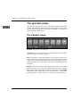
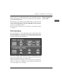
The operator panel
The operator panel allows you to control the printer and change
settings. The indicator lamps show the current status of the printer.
The meaning and function of the buttons depends on the current
operating mode of the printer.
The indicator lamps
POWER: The printer is switched on.
ALARM: An error is present which is preventing normal printing
operation (paper jam, end of paper).
SEL: The printer is ready (ON LINE) to receive data from the computer. If this lamp is not lit, the printer is in OFF LINE mode and not
ready to receive data. If the lamp is blinking, the printer is in print
suppress mode and is ignoring all data sent to it until this mode is
cancelled.
MENU: The menu mode is activated. In this mode, you can alter
printer settings as you wish and permanently store these settings.
The menu mode is described in detail in Chapter 4. The MENU
lamp blinks if the temperature control mechanism has reduced the
printing speed in order to prevent overheating of the print head.
2-4
Chapter 2: A guided tour of the printer
The buttons
Micro Feed Down: The paper is transported backwards in steps of
1/180 inch (downwards). Simultaneously press the SHIFT and
Down buttons to be able to use the »Micro Feed Down« function.
Micro Feed Up: The paper is transported forwards in steps of 1/180
inch (upwards). Simultaneously press the SHIFT and Up buttons to
be able to use the »Micro Feed Up« function.
SHIFT: To be able to use the bottom button functions such as
MENU and TOF, simultaneously press the SHIFT button and the
corresponding button.
SEL: Switches the printer ON LINE or OFF LINE as you wish. The
associated indicator lamp is switched on or off. Pressing the SEL
button also cancels a currently running self test, which is described
in Chapter 6.
The assignment of the buttons mentioned below is independent of
the operating status of the printer. If the printer is in ON LINE or
OFF LINE mode, the functions named at the top of the buttons are
effective.
Button functions in
ON LINE /
OFF LINE mode
2-5
Chapter 2: A guided tour of the printer
LF: Pressing this button (Line Feed) causes the printer to feed the
paper forwards by one line. If a cut sheet feeder is fitted (accessory)
and there is no paper in contact with the platen, pressing this button will cause a new sheet of paper to be fed from the current paper
tray to the first printable line on the paper.
FF/LOAD: Pressing this button (FF, Form Feed) causes the printer
to transport the next sheet of paper to the top of the page and eject
the previous one. If a cut sheet feeder is in use, a new sheet of paper
is fed in as far as the top of the page. If continuous paper is in use
and being fed from the back or below, the paper is advanced to the
next top of form position.
TEAR: The top edge of the sheet is transported beyond the top of
the page to the form tear-off position so that continuous paper already printed can be torn off. How to change the tear-off position is
described further on.
PARK: You can use this button when continuous paper is inserted
to change over to cut sheet feed temporarily without having to remove the continuous paper from the printer. Pressing this button
causes continuous paper that is being fed from the back or below to
be pulled back to the park position in order to free the paper path
for cut sheets. The »Park« function is described further on.
QUIET: In quiet mode, the printing noise typical for matrix printers
is alleviated by reducing the printing speed. You activate or deactivate quiet mode by pressing this button. When quiet mode is activated, the associated indicator lamp lights.
TOF: This button is used to set the first printable line or top of page
(Top Of Form, TOF) for continuous paper. If there is no sheet in the
paper path, the Top Of Form is reset to the standard setting (8.9 mm
or 1/3 inch).
2-6
Chapter 2: A guided tour of the printer
In this mode, you can adjust the printer to your individual requirements. The functions you select are automatically activated when
you switch on the printer.
Button functions in
menu mode
The alterations you make in the printer menu are stored in the
printer and consequently become standard settings. They can however be changed again by software commands, via the operator
panel or by resetting the menu.
The menu options and how to use the menu are described in detail
in Chapter 4.
Print functions
Basic print functions can be adjusted by means of the function buttons described below. To do this, press the appropriate button until
the required indicator lamp lights. You can change the functions in
both ON LINE and OFF LINE mode.
In order to change a print function such as »Print Quality« (font
type) or »Character Pitch« (character width), press the corresponding button until the setting you require is lit.
This part of the operator panel always indicates the current printer
status. If a function is affected by a programming command, the
associated display is also changed.
2-7
Chapter 2: A guided tour of the printer
PRINT QUALITY
Further information on
printing speed and print
quality is to be found in
“Appendix A: Technical
Data”.
The PRINT QUALITY button enables you to determine the print
quality and the font you require for the document to be printed. An
indicator lamp shows the currently activated font and print quality.
There are two print qualities available:
• LQ, Letter Quality: in letter quality, text is printed out with the
highest resolution. The fonts listed below are available in this
quality. Use one of these fonts when you wish to print highquality documents.
Courier
> COURIER is lit
Prestige
> PRESTIGE is lit
Roman
> COURIER and GOTHIC are lit
Swiss
> PRESTIGE and BOLD are lit
Swiss Bold > BOLD is lit
Gothic
> GOTHIC is lit
• UTILITY: In data processing quality, printing is faster, but the
resolution is not as good as letter quality. In data processing
quality, there is no choice of fonts.
You can print a list of the available fonts and their appearance. This
is described in Chapter 8.
CHARACTER
PITCH
These settings determine the width of a character in characters per
inch (cpi). The settings 10, 12, 15, 17.1 and 20 cpi are available. The
setting, also known as pitch is normally 10 or 12 cpi for standard
texts. However, should you wish to print more information on one
page, in sheets of calculations for example, it is advisable to use a
character pitch of 15, 17 or 20 cpi. Proportional spacing (PROP)
makes the text more readable and gives it a typeset-like appearance.
Remember that the printing speed is reduced for fonts of higher
quality.
The »Print Quality« and »Character Pitch« functions can also be
controlled by means of the software.
2-8
Chapter 2: A guided tour of the printer
To reset the printer to the settings selected in the menu, switch the
printer OFF LINE and simultaneously press the buttons SHIFT and
RESET. The printer switches to ready to print status (ON LINE).
RESET
2-9
Chapter 3: Paper handling
Chapter 3: Paper handling
This chapter explains the different ways the printer handles paper
(feeding, setting of printing position, changing between different
types of paper).
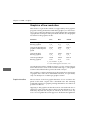
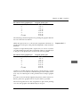
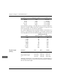
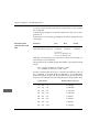
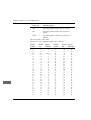
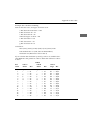
Notes on paper types
• Always use good quality standard paper!
Cut sheets
Feeding from ...
Weight
Top
52 - 90 g/m2
Continuous paper
Rear/bottom
Single-part
Multi-part, NCR paper (sheet)
Multi-part with carbon paper (sheet)
Please also read the notes in
Appendices A and E.
45 - 90 g/m2
38 - 41 g/m2
38 - 45 g/m2
Labels
Bottom
34 - 41 g/m2
Transparencies
Top
≤ 0.1 mm
• The printer will also handle heavier weight paper sheets, multipart paper, paper stickers on backing paper, etc.
• Recycled paper can also be used provided it matches the general
paper specification. There may be a slight loss of quality due to
the generally rougher quality of the paper.
• Do not use damaged sheets as the paper may be fed in incorrectly or may cause a jam.
• Unopened packets of paper should be kept flat in a cool, dry
room until used. As soon as a packet is opened, the unused
paper should be kept in a plastic bag. This will protect the paper
against ambient moisture.
• In order to ensure fault-free handling and the best print quality, it is best to carry out one or more trial prints before performing large print runs.
3-1
CHAP_03.PM6
1
18.04.1997, 12:00 Uhr
Chapter 3: Paper handling
Paper lever
Move the paper lever on the right side of the printer to the position
that is appropriate to the feed path for the paper.
BOT
TOP
REAR
Continuous paper feeding: for continuous paper which is fed via the
bottom or pull tractor
feed, the lever must be
in the BOT (bottom) position.
Cut sheet feeding: for
feeding cut sheets via either the paper support
or the cut sheet feeder,
the lever must be in the TOP position.
Continuous paper feeding: if continuous paper is being fed
from the back via the push or pull tractor feed, move the
lever to REAR.
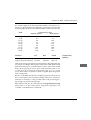
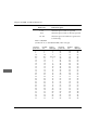
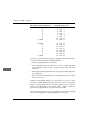
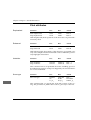
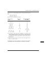
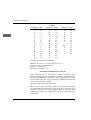
Adjusting for the paper thickness
Print head lever
3-2
The gap between the print head
and platen is adjusted to the paper thickness or multi-part paper by means of the blue, fiveposition print head lever on the
left side of the ribbon drive.
Chapter 3: Paper handling
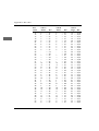
Paper thickness
Lever position
0.08 mm
1
0.15 mm
2
0.22 mm
3
0.29 mm
4
0.36 mm
5
Should you wish to print on thick types of paper, the gap between
print head and platen must be increased:
Adjusting the print
head gap
Caution!
The print head moves and can cause injury to the hands.
Switch the printer OFF LINE and wait until the print head stops
moving.
Caution!
The print head may be hot and can burn your hands.
Wait until the print head has cooled down.
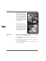
1. Switch off the printer and
open the printer cover.
2. Remove the ribbon cassette
from the holder (see also
Chapter 6).
3-3
Chapter 3: Paper handling
3. Release the locking plate of
the print head by moving the
plate upwards and sideways.
Locking plate
4. Remove the locking plate
and place it to one side.
5. Remove the print head from
its slot.
6. Take out the spacing plate.
Spacing plate
3-4
Chapter 3: Paper handling
7. Insert the plate in front of the
print head holder, making
sure that the plate fits evenly.
Print head holder
8. Replace the print head in the
slot of the print head carriage.
9. Place the locking plate onto
the print head holder, making sure that the pin on the
left of the holder properly
fits into the hole in the locking plate.
Hole in locking plate
3-5
Chapter 3: Paper handling
10. Pivot the locking plate down
thus securing the print head.
11. Replace the ribbon cassette.
12. Close the cover of the printer
and switch on the printer.
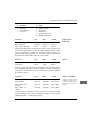
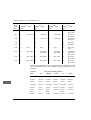
By repositioning the distance plate, the gap between the print head
and the platen is increased. You are now able to print onto materials
of the following thickness:
3-6
Paper thickness
Lever position
0.48 mm
1
0.55 mm
2
0.62 mm
3
0.69 mm
4
0.76 mm
5
Chapter 3: Paper handling
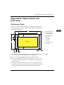
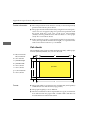
Paper feed: cut sheets
The paper support ensures precise automatic feeding of cut sheets.
1. Move the paper lever on the
right of the printer to the
TOP position (cut sheet).
2. Switch the printer on.
3. Raise the paper support by
lifting it at the back and sliding it into its locking position
Warning!
Direct pressure on the platen can cause damage to the print
head and pins.
Make sure the paper guide is correctly adjusted.
3-7
Chapter 3: Paper handling
4. Insert a sheet of paper into
the paper support and adjust
the rails of the paper guide
so that they just touch the
edges of the paper. Start by
aligning the left edge of the
paper to the mark provided.
The paper is automatically
fed into the printer after the
time set in the menu.
☞
Note!
The left edge of the paper must be no more than 1.2 cm from
the end of the platen.
5. Redefine the top of form if necessary by means of the »Top Of
Form« function as described further on.
Paper feed: continuous paper
Long lists and large printing jobs are typical applications for continuous paper, which can be fed in from the bottom or rear of the
printer as required.
Feeding continuous
paper from the rear
(internal tractor)
3-8
1. Move the paper lever on the
right of the printer to the
»Continuous paper, REAR«
position.
Chapter 3: Paper handling
2. Press downwards on the
back of the paper support.
This will release it from its
catch. Remove it from the
printer and place it to one
side.
Warning!
Direct pressure on the platen can cause damage to the print
head and pins.
Make sure the paper guide is correctly adjusted.
3. Release the catch lever of the
left sprocket drive, adjust
this to the required position
and fasten the sprocket drive
again.
3-9
Chapter 3: Paper handling
4. Open the top part of the cover.
5. Place the continuous paper
onto the first sprocket pins
and close the cover again.
6. Adjust the right sprocket drive to suit the width of paper as described above. Open the cover of the right sprocket drive, place
the continuous paper onto the first sprocket pins and close the
cover.
7. Replace the paper support
and switch the printer on.
The print head will move to
the left end of the platen, the
active lamps of the operator
panel
will
light.
The
ALARM lamp that lights in
this case indicates that there
is no paper at the printing
position.
8. Press the FF/LOAD button,
the paper is now transported
to the initial printing position.
3-10
Chapter 3: Paper handling
9. Set the top of form if necessary with the »Top Of Form« function.
This is described later in the manual.
If the tractor feed is installed, you can also feed continuous paper
from the bottom. This option is available if you have a printer stand
or table with a slot which allows continuous paper to be fed in from
below.
Feeding continuous
paper from the
bottom (tractor feed,
accessory)
Installation of the tractor feed and paper handling is described in
the chapter »Accessories«.
An additional bottom tractor feed gives you the means of feeding
continuous paper from the bottom. In order to be able to use this
function, you first have to fit the bottom tractor feed to allow the
printer to be placed on the built-in supports.
Feeding continuous
paper from the
bottom (tractor feed,
accessory)
Installation of the bottom tractor feed and paper handling is described in the chapter »Accessories«.
Switching between continuous paper and
cut sheets (Park)
Your printer will allow you to switch without difficulty between
printing on continuous paper and cut sheets. The continuous paper
is removed from the paper path at the press of a button. You can
then insert a cut sheet of paper which the printer will then draw in
automatically.
☞
Note!
Do not use the PARK function in conjunction with the pull
tractor feed otherwise the continuous paper will run completely
out of the tractor guide.
3-11
Chapter 3: Paper handling
Changing from
continuous paper to
cut sheets
If continuous paper is being fed from the rear and you wish to
change to cut sheets, proceed as follows:
Do not forward paper to the
PARK position by using the
platen knob.
2. In ON LINE mode, press the PARK button. The continuous paper is transported backwards but remains held in the tractor
feed.
1. Part the already printed pages along the perforation.
3. Move the paper lever on the right of the printer to the middle
position. The symbol for cut sheet handling (TOP) shows you
the correct lever position.
4. Raise the paper support.
5. Place a sheet of paper on the paper support. Adjust the paper
guide to the correct width. Start by aligning the left edge of the
paper to the mark provided.
6. The paper is automatically fed in after the time set in the menu.
If necessary, reset the top of form.
Changing from
cut sheets to
continuous paper
Should you wish to go back to continuous paper when you have
finished printing, proceed as follows:
1. Press the FF/LOAD button to eject the cut sheet still in the printer. Do not use the platen knob to do this otherwise you will lose
the top of form position you have set.
2. Move forwards the paper release lever on the right side of the
printer; the symbol for continuous paper (REAR) shows you the
correct position for the lever.
Do not forward paper to the
PARK position by using the
platen knob.
3. Press the FF/LOAD button again. The continuous paper previously removed from the paper path is drawn around the platen
again.
This function is also available when you use an automatic cut sheet
feeder (accessory).
3-12
Chapter 3: Paper handling
Setting the top of page (Top Of Form)
With the »Top Of Form« function, you can set the line where printing is to start, the so-called top of form.
A clear paper guard is fitted at
the front on the print head carriage. The red line (arrow) is the
position on the current line at
which the characters are printed. This line is very useful when
setting the top of form position
and during general printer operation.
☞
Note!
If you are using the "Form Tear-Off" function, you first have to
switch this off in the printer menu.
Should you wish to change the start of printing in the vertical direction (top of form), proceed as follows:
Changing Top of
Form
1. Transport the continuous paper to the next top of form or insert
a cut sheet and let the printer automatically draw it in. Both
occur on pressing the FF/LOAD button.
If you are using, for example,
a text processing program
which automatically sets a top
margin, the top edge of the
paper is to be set as the top of
form.
2. Switch the printer OFF LINE by pressing the SEL button; the
SEL lamp lights.
3. Set the top of form by holding down the SHIFT button and simultaneously pressing one of the Micro Feed buttons. This will cause
the paper to be transported Up or Down in steps of 1/180 inch.
Do not forward paper to the
new top of form position by
using the platen knob.
4. The top of form chosen is stored once you have released the buttons. Switch the printer ON LINE again by pressing the SEL button.
3-13
Chapter 3: Paper handling
☞
Note!
To set the top of form to the standard setting, simultaneously
press the SHIFT and TOF buttons. There must be no paper in
the print path when doing this.
5. The top of form can be set differently for each type of paper feed,
irrespective of whether you are feeding cut sheets manually, using the cut sheet feeder (CSF) or using continuous paper.
Indicating or changing the print position
The current print position is indicated by the »M« above the red line
located on the clear paper guard of the print head carriage.
Should you wish to find out
where the next printing position
will be, simultaneously press
the SHIFT and PRINT QUALITY
buttons. The print head carriage
will then move automatically to
the new printing position.
If, when printing on pre-printed
forms it is necessary to correct
the current printing position in
a horizontal direction or change
to the next printing position,
proceed as follows:
Print position (M)
1. Make sure that the printer is ON LINE; the SEL lamp lights.
2. Simultaneously press the SHIFT and TEAR buttons and the
print head will move to the left. On pressing the SHIFT and
PARK buttons, the print head will move to the right.
The distance the print head moves between the individual printing
positions corresponds to the setting displayed under CHARACTER
PITCH.
3-14
Chapter 3: Paper handling
Automatic advance to Form Tear-Off
position
If this function is active, printed pages of continuous paper are
transported from the TOF position to the Form Tear-Off position to
allow you to tear them off there. To do this, the continuous paper
must be fed from the rear or via the additional bottom tractor feed
(accessory) from below.
☞
Note!
Do not use the »Form Tear-Off« function in conjunction with
continuous labels on backing paper or with multi-layer forms
as this can cause a paper jam.
Activate this function after setting the top of form position by
means of the menu item Form Tear-Off for the paper path Rear
Feed (rear of printer) or Bottom Feed (bottom tractor feed) by
changing it from Off to the required time pause. After a 500 ms, one
or two second pause without any further print data, the paper is
transported to the tear-off position. You can then tear off the paper
if you wish.
Use of the printer menu is
described in Chapter 4.
The serrated tear-off edge,
which you can use when the top
part of the printer cover is folded forwards, is provided for
this purpose.
If further data is sent to the
printer, the page is pulled back
to the current printing position
or top of form.
Serrated tear-off edge
3-15
Chapter 3: Paper handling
Checking the top of
form
With the »Form Tear-Off« function activated, you can check and set
the top of form by pressing the TEAR button in OFF LINE mode;
the paper is drawn back to the top of form. Reset the top of form by
pressing the Micro Feed Up/Down buttons with the SHIFT button
pressed. The paper is transported to the tear-off position after making this setting.
Changing the tearoff position
Should you wish to change the setting of the tear-off position,
switch the printer OFF LINE with the Form Tear-Off function activated. Make sure the paper is at the tear-off position. Change the
tear-off position by pressing the Micro Feed Up/Down buttons with
the SHIFT button pressed.
Do not forward paper to the
tear-off position by using the
platen knob.
When using graphics programmes, there may due to the amount of
processing to be performed by the computer be pauses in the sending of data which cause the paper to be fed to the tear-off position.
The unnecessary transporting of the paper can impair accurate
registration of the graphics. In this situation, switch off the »Form
Tear-Off« function.
3-16
Chapter 4: Printer menu settings
Chapter 4: Printer menu settings
The printer menu
The printer menu is used to adjust your printer to suit the application. Thus, you can use the printer menu to choose the emulation.
You can adjust the page length for continuous paper or cut sheets,
change the font and make other settings. The changes made in the
menu are stored in the printer and retained even after the printer is
switched off. These settings can be changed by software commands
from your application or by means of the operator panel. After
switching the printer on or off, the values set in the menu come into
force again. Changes to the printer menu are also retained if the
mains power supply is disconnected from the printer.
The printer menu is structured as follows: at the top level, the functions are divided into so-called menu groups (GROUP). Within
each group are to be found several menu items (ITEM). To each
menu item in turn can be assigned a menu value (SET).
In order to change the value of a menu item, you must first call
menu mode. To do this, hold down the SHIFT button and press the
MENU button while the printer is in ON LINE mode. The menu
mode can also be activated by holding down the MENU button
when switching on the printer. This second option is still open to
you when the operator panel is blocked by means of the Operator
Panel Function. The menu mode is activated when the indicator
lamp MENU is lit. The functions beneath the buttons are then
activated.
Activate menu
mode
Should you wish to print out the current menu settings, insert a
sheet of paper in the printer and press the PRINT button. The menu
will be printed out in data processing quality. If, in menu mode, the
printing reaches the end of the paper, insert a new sheet and switch
the printer ON LINE again. The print-out is immediately recommenced.
Print menu settings
There must be paper in the
printer.
4-1
Chapter 4: Printer menu settings
Changing the menu
settings
• On pressing the GROUP button, the next group and the first
menu item associated with it are output. If you simultaneously
press the SHIFT button, the preceding menu group is selected.
• By means of the ITEM button, you can switch to the next menu
item within a group. If you simultaneously press the SHIFT button, the preceding menu item is selected.
• Pressing the SET button causes the current setting of a menu
item to be changed by displaying and activating the next available value. If you simultaneously press the SHIFT button, the preceding value is printed and activated.
• After setting the required value, you can select the next ITEM or
next GROUP in order to make changes to the values there.
• After changing all the items you require, you can end menu
mode by pressing the EXIT button when holding down the
SHIFT button and the changes become effective.
• In order to reset the menu to its factory default, hold down the
two buttons LF and SEL when switching the printer on.
☞
Note!
Within menu mode, you can print out by means of the PRINT
button a complete list of menu items with the current settings.
Example
Ex factory, the printer is set to character pitch 10 cpi. In order to
create a wide table you wish to use character pitch 17.1 cpi. Proceed
as follows:
1. The printer is in ON LINE mode. First press the SHIFT button,
hold this down and then press the MENU button.
2. Press the GROUP button to switch from the first group Printer
Control to the next group Font.
3. Press the ITEM button to switch from the first menu item Print
Mode to the next menu item Pitch.
4-2
Chapter 4: Printer menu settings
4. You can select a value for Pitch. Since the first value is 10 cpi,
you need to press the SET button three times until the value 17.1
cpi appears.
Hold down the SHIFT button and press the EXIT button. The values last selected now become effective and the printer returns to
print mode.
End menu mode
Below are summarised the functions for buttons in menu mode:
Button
Function
SHIFT/MENU
Pressing both buttons in ON LINE
status activates menu mode.
GROUP
Calls the next group.
SHIFT/GROUP
Calls the previous group.
ITEM
Displays the next menu item within the
current group.
SHIFT/ITEM
Displays the previous menu item within
the current group.
SET
Displays the next value of the current
item.
SHIFT/SET
Displays the preceding value of the
current item.
PRINT
Prints out all menu items and the associated settings.
SHIFT/EXIT
Ends menu mode.
4-3
Chapter 4: Printer menu settings
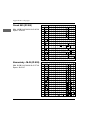
GROUP
The factory defaults for menu
items are printed in bold.
The font LQ Orator can only
be selected via the menu and
not via the operator panel
ITEM
Printer Control
Emulation Mode
Font
Print Mode
Pitch
Proportional Spacing
Symbol Sets
EPSON LQ, IBM PPR,
IBM AGM
LQ Courier, LQ Roman,
LQ Swiss, LQ Swiss Bold,
LQ Orator, LQ Gothic,
LQ Prestige, Utility
10 CPI, 12 CPI, 15 CPI,
17.1 CPI, 20 CPI
No, Yes
Style
Normal, Italics
Size
Single, Double
Character Set
Set II, Set I
Language Set
ASCII, French, German,
British, Danish I, Swedish I,
Italian, Spanish I, Japanese,
Norwegian, Danish II,
Spanish II, Latin American,
French Canadian, Dutch,
Swedish II, Swedish III,
Swedish IV, Turkish,
Swiss I, Swiss II, Publisher
Zero Character
Code Page
Slashed Letter O
4-4
SET
Unlashed, Slashed
USA, Canada French,
Multilingual, Portugal,
Norway, Turkey, Greek_437,
Greek_869, Greek_928,
Greek_437 Cyprus, Polska
Mazovia, Serbocroatic I,
Serbocroatic II, ECMA-94,
Hungarian CWI, Windows
Greek, Windows East
Europe, Windows Cyrillic,
East Europe Latin II-852,
Cyrillic I-855, Cyrillic II866, Kamenicky (MJK), ISO
Latin 2, Hebrew NC-862,
Hebrew OC, Turkey_857,
Latin 5 (Windows Turkey),
Windows Hebrew,
Ukrainian, Bulgarian, ISO
Latin 6 (8859/10), Windows
Baltic, Baltic_774
No, Yes
Chapter 4: Printer menu settings
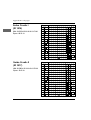
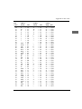
GROUP
Rear Feed
ITEM
Line Spacing
6 LPI, 8 LPI
Form Tear-Off
Off, 500 ms, 1 sec, 2 sec
Skip Over Perforation
Bottom Feed
No, Yes
Page Width
13.6 ", 8 "
Page Length
12 ", 14 ", 17 ", 3 ", 3.5 ",
4 ", 5.5 ", 6 ", 7 ", 8 ", 8.5 ",
11 ", 11 2/3 "
Line Spacing
6 LPI, 8 LPI
Form Tear-Off
Off, 500 ms, 1 sec, 2 sec
Skip Over Perforation
Top Feed
SET
No, Yes
Page Width
13.6 ", 8 "
Page Length
12 ", 14 ", 17 ", 3 ", 3.5 ",
4 ", 5.5 ", 6 ", 7 ", 8 ", 8.5 ",
11 ", 11 2/3 "
Line Spacing
6 LPI, 8 LPI
Bottom Margin
The menu item Page Width
appears only for wide printer
models.
Valid, Invalid
Page Width
13.6 ", 8 "
Page Length
11 2/3 ", 12 ", 14 ", 16.57 ",
3 ", 3.5 ", 4 ", 5.5 ", 6 ", 7 ",
8 ", 8.5 ", 11 "
Wait Time
1 sec, 2 sec, 500 ms
Page Length Control
The menu item Page Width
appears only for wide printer
models.
The menu item Page Width
appears only for wide printer
models.
by MENU Setting,
by Actual Page Length
4-5
Chapter 4: Printer menu settings
GROUP
Set-Up
ITEM
SET
Graphics
Uni-directional,
Bi-directional
Receive Buffer
8 K, 23 K, 1 Line
Paper Out Override
Print Registration
Operator Panel Function
No, Yes
0, 0.05mm, 0.10mm, 0.15mm,
0.20mm, 0.25mm Left,
0.25mm Right, 0.20mm,
0.15mm, 0.10mm, 0.05mm
Full Operation,
Limited Operation
Reset Inhibit
No, Yes
Print Suppress Effective
Yes, No
Auto LF
No, Yes
Auto CR appears only when
IBM emulation is selected.
Auto CR
No, Yes
CSF Bin Select appears only
when cut sheet feeder is
installed with two trays.
CSF Bin Select
SI Select Pitch (10/12 cpi)
appears only when IBM
emulation is selected.
SI Select Pitch (10 CPI)
17.1 CPI, 15 CPI
SI Select Pitch (12 CPI)
12 CPI, 20 CPI
Time Out Print
Valid, Invalid
Auto Select
Graphics Speed
MODE2 appears only for
wide printer models.
CSF Type appears only for
wide printer models.
4-6
Bin 1, Bin 2
Centering Position
CSF Type
No, Yes
Low, High
DEFAULT, MODE1, MODE2
Wide, Narrow
Chapter 4: Printer menu settings
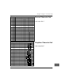
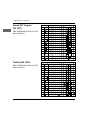
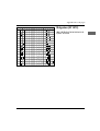
GROUP
Parallel I/F
ITEM
SET
I-Prime
Buffer Print,
Buffer Clear, Invalid
Pin 18
+5 V, Open
Auto Feed XT
Invalid, Valid
Auto Feed XT appears only
when Epson emulation is
selected.
The menu items of the group Serial I/F only appear when a serial
interface is installed. The installation is described in the »Accessories« chapter, further technical information on interfaces is to be
found in the «Interface Data« appendix.
GROUP
Serial I/F
ITEM
Parity
Serial Data 7 / 8-Bits
Protocol
Diagnostic Test
SET
None, Even, Odd
8 Bits, 7 Bits
Ready / Busy,
X-ON / X-OFF
No, Yes
Busy Line
SSD-, SSD+, DTR, RTS
Baud Rate
9600 BPS, 4800 BPS,
2400 BPS, 1200 BPS, 600 BPS,
300 BPS, 19200 BPS
DSR Signal
Valid, Invalid
DTR Signal
Ready on Power Up,
Ready on Select
Busy Time
200 ms, 1 sec
4-7
Chapter 4: Printer menu settings
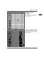
The menu items of group CSF Bin 1 listed below appear only when
a cut sheet feeder is installed. The menu items of the group CSF
Bin 2 accordingly appear only when a cut sheet feeder is installed
with two trays.
GROUP
CSF Bin 1
ITEM
Line Spacing
Bottom Margin
Page Width appears only for
wide printer model.
CSF Bin 2
6 LPI, 8 LPI
Valid, Invalid
Page Width
13.6 ", 8 "
Page Length
11 2/3 ", 12 ", 14 ", 16.57 ",
3 ", 3.5 ", 4 ", 5.5 ", 6 ", 7 ",
8 ", 8.5 ", 11 "
Line Spacing
6 LPI, 8 LPI
Bottom Margin
Page Length
4-8
SET
Valid, Invalid
11 2/3 ", 12 ", 14 ", 16.57 ",
3 ", 3.5 ", 4 ", 5.5 ", 6 ", 7 ",
8 ", 8.5 ", 11 "
Chapter 4: Printer menu settings
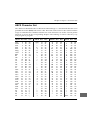
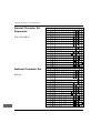
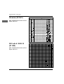
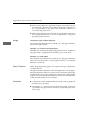
Explanation of menu items
Emulation Mode: You use this item to define the command set. The
emulations available to you are Epson LQ, IBM ProPrinter and
IBM AGM. The Alternative Graphics Mode (AGM) includes partial
compatibility with the Epson LQ series which is largely limited to
graphics and line feed commands. The commands available in
AGM are indicated in the appropriate chapters.
Printer Control
Print Mode: You can select here the required font for the document.
Font
Pitch: You set here the character width in characters per inch (cpi).
Proportional Spacing: The fonts in letter quality can optionally be
printed with proportional spacing.
Style: You select normal or italic characters.
Size: You can switch between single font size and combination of
expanded horizontal and vertical font.
Character Set: You can select here between IBM character sets Set I
and Set II. In Epson emulation, Set II corresponds to an extension of
the printable characters.
Symbol Sets
Language Set: When you select a national character set, this replaces some characters with the special characters of the respective language.
Zero Character: Select Slashed if you wish zero to have a slash
through it in order to better differentiate it from capital O.
Code Page: A code page is a character set that contains country
specific characters. In IBM emulation it can be used as character set
I and II or as a fully printable character set. In Epson emulation, all
characters can be made available via the "Extension of printable
characters". In addition, certain characters in the lower range can be
replaced by choosing a national character set (Language Set).
A table of all the character
sets and code pages is to be
found in Chapters 10, 14 and
Appendix B.
Slashed Letter O: The characters ¢ (155) and ¥ (157) are replaced by
Ø and Ø when Yes is selected.
4-9
Chapter 4: Printer menu settings
Rear Feed,
Bottom Feed
Line Spacing: Select between 6 lpi (lines per inch, corresponds to
1/6 inch line spacing) or 8 lpi (corresponds to 1/8 inch line spacing).
Form Tear-Off: If this function is activated, continuous paper is
automatically transported to the tear-off position after the time preset in the menu (500 ms, 1 sec, 2 sec). The OFF setting switches the
Form Tear-Off function off. Further information on this function is
to be found in the chapter »Paper Handling«.
Skip Over Perforation: Select Yes if you wish continuous paper to
be automatically transported to the top of the next page 2.54 centimetres (1 inch) before it reaches the bottom edge of the page. If page
formatting is performed by the software, set this item to No in order
to avoid problems.
Page Width: This menu item is only offered with wide printer models. Select the page width for the paper you are using. The standard
setting is 13.6 inch.
Page Length: Select here the page length for the paper you are
using to ensure the initial printing position is the same for each
page.
Top Feed
Line Spacing: select between 6 lpi (lines per inch, corresponds to
1/6 inch line spacing) or 8 lpi (corresponds to 1/8 inch line spacing).
Bottom Margin: When Valid is set, a bottom margin of one inch
(2.54 cm) is always left unprinted when feeding cut sheets via the
paper support or when using an automatic cut sheet feeder.
Page Width: This menu item is only offered with wide printer models. Select the page width for the paper you are using. The standard
setting is 13.6 inch.
Page Length: Select here the page length for the paper you are using to ensure the initial printing position is the same for each page.
The page length set here is only used if the value By MENU Setting
has been selected in the menu item Page Length Control.
Wait Time: Where cut sheets are being fed from above via the paper support, the sheets are automatically drawn after the preset
time.
4-10
Chapter 4: Printer menu settings
Page Length Control: Where cut sheets are being fed from above
(Top Feed), the page length can be set via the menu or program
commands (by Menu Setting). If, however, you set the value by
Actual Page Length, the page length is automatically detected by
means of the end of page sensor.
Graphics: Select Uni-directional (from left to right only) to achieve
more precise registration of graphics. With Bi-directional, the
printing speed is increased.
Set-Up
Receive Buffer Size: Selects the volume of the receive buffer. If you
set a large size for the receive buffer, the system can send greater
volumes of data to the printer which then stores it in the buffer; the
printer is ready to receive data for a longer period and the transfer
of data from the computer is therefore not interrupted. If the receive
buffer becomes full, however, the printer is not ready to receive for
a longer period because of the large volume of data in the buffer
which it has to process. If your system issues an error message
when the buffer is set to a large size (e.g. unit error through timeout), you need to set a smaller buffer. The result is that the time
intervals during which the printer is not ready to receive are shorter. Your system is consequently able to send data to the printer at
shorter intervals.
In general, it is advisable to set the receive buffer as small as possible where the computer places the print data in temporary storage
(»spooling«) by means of a print manager, for example. This applies to large and medium-sized data processing systems and when
the printer is used in a network.
Paper Out Override: If the paper end sensor detects that there is
less than 1 inch (2.54 cm) of paper left in the printer, it stops a current print job. If you set Yes, the sensor is deactivated thus enabling
you to print to the bottom edge of the page when using cut sheets of
paper. Make sure when setting Yes that the printer does not print
on the platen.
Print Registration: Use this item during bi-directional printing in
order to improve the horizontal registration. Normally, the appropriate value is 0, although by setting another value you can alleviate possible registration problems when printing graphic data.
4-11
Chapter 4: Printer menu settings
Operator Panel Functions: Normally, all the buttons of the operator panel are active, but if you choose Limited Operation, the buttons PRINT QUALITY, CHARACTER PITCH and menu mode are
blocked. The corresponding functions can then only be controlled
by the software. This function is particularly suitable for printers
being used by one or more persons where the changing of settings
is undesirable. Hold down the MENU button when switching on to
call the menu in Limited Operation mode.
Reset Inhibit: Select Yes if you wish to suppress the initialisation
command sent by the software or system. This initialisation command resets all the functions to the values you have set in the menu.
Print Suppress Effective: If the value Yes is selected in this menu
item, the commands for print suppression are active in all emulations. If the value No is selected, the commands for print suppression are ignored.
Auto LF: After selecting Yes, the printer automatically adds a line
feed each time it receives a carriage return command. Check whether your computer also adds a line feed. If your print-outs always
have double-line spacing, you should select No. If lines are printed
on top of each other, Yes is the correct value.
Auto CR applies only to IBM
emulation.
Auto CR: If you wish the printer to perform a carriage return automatically each time it receives the line feed command, select Yes at
this position.
CSF Bin Select appears only
when an optional cut sheet
feeder with two trays is
installed.
CSF Bin Select: If you are using a cut sheet feeder with two bins,
you can use this menu item to select one of these two bins as the
standard bin and set different positions for the initial print line (top
of form) for both bins. After quitting the menu, you can change the
top of form position for the bin selected in the menu.
SI Select Pitch (10 cpi) and
SI Select Pitch (12 cpi)
apply only to IBM emulation.
SI Select Pitch (10 cpi): You can define here whether the command
SI in IBM emulation selects a character pitch of 17.1 cpi or 20 cpi
when 10 cpi is used.
SI Select Pitch (12 cpi): You can define here whether the command
SI in IBM emulation selects a character pitch of 20 cpi or retains
12 cpi.
Time Out Print: If this function is activated and the printer receives
no data for 150 ms, the data in the printer buffer is printed out.
4-12
Chapter 4: Printer menu settings
Auto Select: If a sheet of paper has been fed automatically from the
paper support when the setting is No, the printer stays in the OFF
LINE status. If Yes is selected, the printer switches to ON LINE
when a sheet of paper is fed and the SEL lamp lights.
Graphics Speed: By means of this menu item, the printing speed
for graphics of a lower resolution can be increased by selecting
High.
Centering Position: This menu item is used to set the preferred position of the print head to suit the width of the paper format to be
printed. The resultant reduction in print head movement optimises
penetration, and over-saturation of the ribbon is largely avoided.
Refer to the table below to choose the recommended menu settings
for the width of the paper format to be printed. Depending on the
type of paper, it may be that the MODE1 and MODE2 settings can
be used with paper widths larger than stated in the table. With
heavier paper that is wider than A4, the DEFAULT setting may be
necessary.
paper
narrower
than 12.5 cm
12.5 to
20.9 cm
21.0 cm
(A4 portrait)
narrow
model
MODE1
MODE1
DEFAULT
---
wide
model
MODE1
MODE2
MODE2
DEFAULT
MODE1, segment 10 to 50
MODE2 only appears for
wide printer models.
wider
than 21.0 cm
(10 characters per inch)
Default, position 60
platen, narrow model
MODE1, segment 10 to 50
MODE2, position 55
Default, position 60
platen, wide model
The diagram shows the
preferred position of the print
head in relation to the
selected menu item. The print
head is driven from this
position to the next print
position, with the shortest
possible path being chosen.
4-13
Chapter 4: Printer menu settings
CSF Type: The menu item CSF Type only appears for wide printer
models. If you are working with a wide cut sheet feeder, the value
must be set to Wide. If you are using a narrow cut sheet feeder with
a wide printer, set the value to Narrow.
Parallel I/F
I-Prime: the signal on the I-Prime line of the parallel interface can
either be ignored (Invalid), cause printing out of the current buffer
(Buffer Print) or erase the print buffer (Buffer Clear).
Pin 18: pin 18 of the parallel interface can be switched to 5 volts or
open if required.
This menu item applies only
to Epson emulation.
Auto Feed XT: In essence, no line feed (LF) is performed after a carriage return (CR) if Auto LF is set to No. If, however, in Epson mode
Auto LF is set to No and Auto Feed XT to Valid, a line feed is performed when an external Auto Feed Signal (Centronics pin 14) is
issued. This special case can be necessary for certain combinations
of hardware and software.
Serial I/F
In the case of serial data transmission, the data bits of a byte are sent
one after the other via a line to the printer. For correct transmission,
it may be necessary to change the interface settings so that they
match the settings of your computer. If there is a serial interface
installed and this has been activated in the menu, the menu items
described below appear.
Parity: Selects the parity. For each byte of data, a start bit with logical value 1 is transmitted, followed by the 7 or 8 bits of data according to the data length defined. If required, a parity bit can follow for
the purpose of data checking.
Serial data 7/8 bits: Defines the data format. It is necessary to differentiate between the data format (7 or 8 bits) and the transmission
format (data bits plus parity bit set or not set).
Protocol: Selects the interface protocol. There are two protocols that
can determine the sending and receiving of data. In the case of the
Ready/Busy protocol, the DTR, RTS or SSD line indicates the printer's readiness to receive by means of the voltage level. In the case of
the X-ON/X-OFF protocol, sending/receiving is controlled (handshake) via special characters transmitted on the data line.
4-14
Chapter 4: Printer menu settings
Diagnostic Test: Activates a diagnostic test of the interface. For further information, please refer to Appendix D.
Busy Line: Defines the line to be used for the busy signal.
Baud Rate: Defines the speed of data transmission.
DSR Signal: Activates or deactivates the DSR signal (data set
ready).
DTR Signal: Defines the status of the DTR signal (data terminal
ready).
Busy Time: Selects the duration of the busy signal.
4-15
Chapter 5: Printer Control
Chapter 5: Printer Control
Emulation
An emulation is a »copy« of the functions of a specified device. That
means your printer is capable in a certain emulation of executing the
commands and functions of this particular device. In addition, extra
functions are in most cases provided that go beyond the performance specification of the emulated device.
To be able to use your printer with as many applications as possible,
it is provided with the emulations IBM ProPrinter, IBM ProPrinter
AGM and Epson LQ.
The IBM ProPrinter function
"Load down user-defined
characters into the printer,
DLL" is not supported by this
printer model.
Printer drivers
In order to be able to write application programs not designed for
specific output devices such as a screen or printer, they are mostly
provided with exchangeable program parts responsible for outputting the data, so-called drivers. A driver receives generally required
outputting instructions from its own program and translates these
into the special commands and functions of the printer for which the
driver was written. When installing or setting up printer drivers,
you should always refer to the manual for the respective program,
as the programs may be available in versions written both at different times and for different countries. For that reason, the notes given
here may not always be applicable to your program but are to be
taken as generally applicable.
You will obtain the best support for your printer if you use a printer
driver which precisely matches the name of your printer.
If there is no matching driver in your program, choose a driver for
one of the emulations named below. Make sure that the printer driver agrees with the emulation you set in the menu of the printer.
To select another suitable printer driver, go through the following
list from top to bottom and select the driver that most closely matches the name of your printer.
5-1
Chapter 5: Printer Control
☞
Note!
The lower the printer driver appears in the list, the fewer the
functions supported.
Epson-Emulation
IBM-Emulation
OKI ML 3390/3391
OKI ML 590/591 Elite
OKI ML 590/591
OKI ML 390/391 Elite
OKI ML 390/391
Siemens High Print 4008-N10/
Siemens High Print 4008-N60
Epson LQ 870/1170
Epson LQ 850/1150
Epson LQ 1500
Epson LQ
OKI ML 3390/3391
OKI ML 590/591 Elite
OKI ML 590/591
OKI ML 390/391 Elite
OKI ML 390/391
Siemens High Print 4008-N10/
Siemens High Print 4008-N60
IBM ProPrinter X24 (4207)
IBM ProPrinter XL24 (4208)
Some software packages permit modification of the printer driver.
Such a modification, however, requires an intensive study of the
program and the control commands of the printer. A list of the available functions and the associated control commands is to be found
in Chapters 10 and 14 of this manual. Please refer to the manual of
your application program for more detailed notes on installation
and modification of the printer driver. If in doubt, contact your software manufacturer or supplier.
5-2
Chapter 5: Printer Control
Characters and control characters
The print data is transmitted by character. Every character is represented by 8 bits and thus expresses a certain position within the
character set currently selected.
Most character sets are based on ASCII code (American Standard Code
for Information Interchange).
There are different national variations for this character set. The socalled control characters are common to all the character sets. These
are to be found at decimal positions 0 to 31 and effect functions such
as page feed, line feed or carriage return. Some of these control characters modify character widths and are described in the appropriate
chapters.
The so-called Escape character has a special significance among the
control characters and is located at decimal position 27 (hexadecimal
1B). This control character introduces most commands for printers.
One or more ASCII characters follow which in conjunction with the
Escape character activate or deactivate print functions. At positions
32 to 255 are normally to be found printable characters. It is often
possible to obtain special printable characters at the positions of the
control characters by triggering them with an appropriate command.
The commands are listed in ASCII, decimal and hexadecimal form.
If you are using a programming language, refer to your programming manual for the transfer of characters and control characters to
the printer.
Printing under DOS
Most IBM PC and compatible PCs use MS-DOS, PC-DOS, DR-DOS
or similar as the operating system. Although DOS has no print functions, like a text processing or graphics program, direct printing of
ASCII or print files is nevertheless possible under DOS. In the examples listed below, it is assumed that the printer is connected to parallel interface LPT1 of the PC. If a different interface to LPT1 is used
(e.g. LPT2, LPT3, COM1, COM2), the address in the examples must
be correspondingly altered. Further details on the serial interface are
to be found later in the manual.
5-3
Chapter 5: Printer Control
TYPE
It is possible to print an ASCII or print file by using the TYPE command and diverting the output to the LPT1 device.
Example:
TYPE C:\AUTOEXEC.BAT > LPT1:
TYPE C:\TEXTS\LETTER.TXT > LPT1:
In the first instance, the file AUTOEXEC.BAT is printed from the
root directory and in the second case the file LETTER.TXT is printed
from the TEXTS subdirectory.
COPY
Files are copied between diskettes and hard disk and other devices
by means of the COPY command. Thus, files can also be transmitted
to the printer by means of COPY. When using the COPY command,
the option »/B« should be activated so that binary and graphics files
can also be copied without any limitations.
Example:
COPY /B C:\AUTOEXEC.BAT LPT1:
COPY /B C:\TEXTS\LETTER.TXT LPT1:
Similarly, one can also copy characters directly from the keyboard to
the printer by means of the COPY command.
Example:
COPY CON: LPT1
THIS IS A SMALL TEST
CTRL-P
Ctrl-Z or F6
After entering the control character CTRL-P (hold down the CONTROL key and press the P key), texts output to the screen are simultaneously output to the current printer output device and printed
out there. If, for example, the command DIR is entered via the keyboard, the file names of the current subdirectory are output not only
to the screen but also to the printer.
For more detailed information on printing under DOS and the commands mentioned above, please refer to the manual for the operating system.
5-4
Chapter 5: Printer Control
Entering the control character CTRL-P once again switches off printing of the screen data on the printer.
Printing under DOS with a serial interface
(RS-232C)
When printing under DOS, make sure only the transmission protocol Ready/Busy (hardware handshake) is supported. Printing with
the transmission protocol X-ON/X-OFF (software handshake) is
only possible with software for remote data transfer such as Telix,
ProCom or MS-Windows Terminal.
Remote data transfer programs of this kind are good for testing interfaces because it is easy to change or adjust the parameters.
Note also the following points:
• The settings for the serial interface in the menu of the printer
must agree with the settings for the serial interface in the PC.
• The interface cable must be wired in accordance with the menu
options.
Example:
The serial interface options in the printer are set at the factory as
follows:
Parity
None
Serial data
8 bits
Protocol
Ready / Busy
Diagnostic Test
No
Busy Line
SSD-
Baud Rate
9.600 bps
DSR Signal
Valid
DTR Signal
Ready on Power up
Busy Time
200 ms
5-5
Chapter 5: Printer Control
• The serial interface settings in the computer are defined with the
MODE command as follows:
MODE COM1: 9600,n,8,1,p
Please refer to the DOS manual for more information on the
MODE command.
• Notes and further information on the serial interface (wiring, pin
assignment, etc.) are to be found in the Interface Data appendix.
Troubleshooting
Should your printer not print under DOS when using a serial connection, go through the following checklist:
1. Check whether there is a technical fault on the serial interface
(RS-232C). To do this, perform the test described in Appendix D.
2. Check the settings of the items in the printer menu which relate
to the serial interface. These settings must agree with the settings
in your system.
3. Make sure the serial interface is correctly set up under DOS.
4. Check the interface cable. With the multitude of cables available,
it is often difficult to find a cable suitable for your particular requirements. The interface cable described in Appendix D can be
used both for transmission protocol X-ON/X-OFF and Ready/
Busy (Busy Line DTR).
5-6
Chapter 6: Consumables and cleaning
Chapter 6: Consumables and
cleaning
Changing the ribbon cassette
If the contrast of the printed characters is deteriorating, the ribbon
needs to be changed. To do this, proceed as follows:
Caution!
The print head moves and can cause injury to the hands.
Switch the printer OFF LINE and wait until the print head stops
moving.
1. Switch the printer OFF LINE by pressing the SEL button; the
SEL lamp is extinguished.
2. Open the printer cover.
Caution!
The print head may be hot and can burn your hands.
Wait until the print head has cooled down.
3. Move the print head to the
middle of the platen.
6-1
Chapter 6: Consumables and cleaning
4. Hold the used ribbon cassette at the top and carefully
lift it over the print head.
Lift cassette over the print head
Inserting a new
ribbon cassette
The original ribbon cassettes of the manufacturer´s are specially developed for your printer. Among other things, this concerns the ink,
which contains lubricants, and the fabric of the ribbon.
Warning!
Non-original ribbons can damage the print head.
Use only the original ribbons of the manufacturer.
A clear ribbon guard is fitted to the front of the cassette. Do NOT
remove it!
1. Take the ribbon out of its plastic packing.
2. Place the cassette with the
cutout sections onto the pins
of the cassette holder.
6-2
Chapter 6: Consumables and cleaning
3. Tilt the cassette carefully
down over the print head
until you feel it click into
place.
4. Turn the blue transport knob
of the cassette in the direction of the arrow to tension
the ribbon.
5. Close the printer cover and
switch the printer ON LINE
again by means of the SEL
button.
Tilt cassette down over print head
Cleaning
To ensure constant problem-free printing, clean the printer every
six months (or after 300 hours of operation).
Caution!
The print head moves and can cause injury to the hands.
Switch the printer OFF LINE and wait until the print head stops
moving.
Caution!
The print head may be hot and can burn your hands.
Wait until the print head has cooled down.
• Before carrying out any cleaning, remove all accessories from
the printer such as the cut sheet feeder or tractor feed.
• Clean the area around the axle of the print head carriage and the
platen with a clean, dry cloth.
6-3
Chapter 6: Consumables and cleaning
• Remove paper dust only with a soft brush such as a paint brush.
• Do not grease or oil any parts within the printer, this can cause
damage.
• Do not use any solvents or aggressive cleaning agents on the
case or in the machine, this can cause damage.
6-4
Chapter 7: Accessories
Chapter 7: Accessories
The accessories described in this chapter extend the range of functions provided by your printer. For your safety, and to avoid damage to the machine:
• ... switch the printer off before installing accessories,
• ... remove the plug from the power supply.
Make sure you also read the safety information at the beginning of
this manual.
Cut sheet feeder
A cut sheet feeder feeds single sheets of paper to the printer thus
saving the operator having to feed paper manually sheet by sheet
during large print jobs (multiple copies of letters, etc.). The printed
pages are ejected onto the output tray.
The cut sheet feeder is available in different versions:
• Narrow sheet feeder with one paper tray
• Narrow sheet feeder with two paper trays (double tray)
• Wide sheet feeder with one paper tray
• Wide sheet feeder with two paper trays (double tray)
Front paper stand (paper eject)
Paper set lever
Rear paper stand (paper insert)
Mounting bracket
7-1
Chapter 7: Accessories
Checking the items
supplied
Check that the individual items
supplied are complete and undamaged. You should have received:
• 1 feed rail
• 1 front paper stand
• 1 to 4 rear paper stands
Remove the packing material. Keep the original packing material
safe so that you can transport the sheet feeder safely at a later date if
necessary.
Adjusting the length
of the feed rail
You will need a cross-head
screwdriver for this.
The metal paper feed rail enables you to fit a narrow cut sheet feeder onto a wide printer. All that is required is to adjust the feed rail to
the wide platen.
1. Undo and remove the
screws on the top of the feed
rail.
Screws
2. Lay the extension piece of
the rail next to the appropriate holes so that they align
on the right hand side.
7-2
Chapter 7: Accessories
3. Align the holes of the extension precisely to the holes of
the rail.
4. Fasten
again.
the
screws
once
Extended in this way, the paper
feed rail will now fit the wide
printer. If, on the other hand,
you are using the narrow printer, the rail must not be extended.
Install the feed rail as follows:
Installing the
feed rail
Caution!
The print head moves and can cause injury to the hands.
Switch the printer OFF LINE and wait until the print head stops
moving.
Caution!
The print head may be hot and can burn your hands.
Wait until the print head has cooled down.
7-3
Chapter 7: Accessories
1. Switch the printer off and
open the printer cover.
2. Remove the paper support
(see also Chapter 1).
3. Remove the ribbed paper
separator by first pulling it
forwards and then removing
it from its catch arrangement
(see also Chapter 1).
4. Fit the feed rail with its
mounting brackets at both
ends of the platen. You
should hear it click into
place.
5. Gently tilt the rail backwards.
7-4
Chapter 7: Accessories
1. Install the cut sheet feeder
with its mounting brackets
onto both ends of the platen
shaft so that it is firmly
seated.
Installing the cut
sheet feeder
2. Turn the platen knob so that
the gearwheel on the left end
of the sheet feeder engages
with the gearwheel of the
platen.
3. Close the printer cover.
4. Connect the cable of the cut
sheet feeder to the printer by
plugging it into the socket
provided to the left rear of
the printer. The arrow on the
plug shows the correct way
to plug it in.
7-5
Chapter 7: Accessories
5. Fit the rear paper stand or
stands as the case may be
onto the rail of the paper
guide.
6. Now insert the front paper
stand.
7. To ensure that the machine
feeds and handles the paper
perfectly, the paper lever at
the right end of the printer
must point to the cut sheet
symbol (middle position,
TOP).
8. Switch the printer on.
7-6
Chapter 7: Accessories
The paper tray of the cut sheet feeder has a maximum capacity of
100 sheets (90 g/m2) or 170 sheets (60 g/m2) of standard paper.
A mark on the left guide rail indicates the maximum amount of
paper. Read also the further notes on paper in Chapter 3.
Paper feed
1. Set the paper set lever at the
right end of the cut sheet
feeder upwards to the RESET position. The paper tray
will open towards the back.
Warning!
Direct pressure on the platen can cause damage to the
print head and pins. Make sure the paper guide is correctly
adjusted.
2. Take a stack of paper, fan it
to part the sheets and insert
it into the sheet feeder. Make
sure the stack of paper is lying on the bottom of the tray.
3. Make sure the rear paper
stands are positioned equally between the paper guides.
Paper
guides
Lever
7-7
Chapter 7: Accessories
4. Adjust the right paper guide
so that the right side of the
guide is flush with the right
edge of the sheet of paper.
Do not force the uprights together. The guide rail can be
released and locked again by
moving the locking lever to
the appropriate position
(RELEASE, LOCK).
5. Move the paper set lever of
the sheet feeder to the SET
position. If it is left released,
the friction rollers cannot
grip the paper and if printing is performed without paper, the print head and platen can be damaged.
Automatic paper
feed
1. Make sure the setting of the menu item Page Length matches the
paper format you are using. Further information on this is to be
found in »Chapter 4: Printer menu settings«.
2. In ON LINE mode, feed the first sheet of paper with the LF or
FF/LOAD button.
3. If necessary, redefine the top of form. This is described in
»Chapter 3: Paper handling«.
4. To eject a sheet of paper, press the FF/LOAD button again. Do
not use the platen knob.
7-8
Chapter 7: Accessories
Cut sheets can also be fed into the printer when the cut sheet feeder
is installed. It is essential, however, that there is no paper in the
normal paper path of the printer. There are two possible modes for
manual feeding:
Manual paper feed
Feeding cut sheets
If the printer is ON LINE while
paper is placed into the manual
feed slot, it becomes the priority
tray for a cut sheet. In the event
of a multi-page print job, the
printer will merely take the first
sheet from the manual feed slot.
All other sheets will be taken
automatically from the current
paper tray of the cut sheet feeder.
Changing over to the manual feed slot
If the printer is OFF LINE while paper is placed into the manual
feed slot, it serves as the manual feed tray. The sheet you have inserted is drawn in automatically after the time set in the Wait Time
menu.
If the Auto Select menu item is set to No, it will be necessary to
press the SEL button after each automatic feed operation. If the
Auto Select menu item is set to Yes, printing begins directly after
the automatic feed operation.
For the subsequent pages of a print job, the printer waits for a further sheet of paper from the feed slot after the first sheet has been
printed and ejected. At the same time, the ALARM lamp is lit and
the SEL lamp is extinguished. Single sheets have to be inserted in
the manual feed slot right to the end of the print job.
Changing over to normal printing operation
To change back to normal printing operation, you merely need to
switch the printer back to ON LINE mode once the print job has
finished. After this, the printer will take the next sheet to be printed
from the current tray of the cut sheet feeder.
7-9
Chapter 7: Accessories
Feeding cut sheets
and continuous
paper
If you are using single-part continuous paper, you can leave the cut
sheet feeder on the printer and alternately feed and process continuous paper and cut sheets from the sheet feeder. To do this, transport the continuous paper into the PARK position as described in
Chapter 3. It is not possible to process multi-part forms with the cut
sheet feeder installed. Use the tractor feed to process multi-part
forms (accessory).
Printing area
Even though the cut sheet feeder permits printing of cut sheets
from the top of the page, it is advisable to leave a top margin of 1/3
inch (0.85 cm) and a bottom margin of 1 inch (2.54 cm) as the print
quality cannot be guaranteed in this area, and there are likely to be
a greater number of paper jams.
The bottom limit of printing is defined by the menu item Bottom
Margin. If Bottom Margin is set to Valid, a bottom margin of 1/2
inch (13 mm) is preset. If, on the other hand, this menu item is set to
Invalid, the bottom margin depends on the page length set in the
menu. The smallest possible bottom margin can be 0.5 mm. In this
case, make sure the page length is correctly set.
Selecting the paper
tray
If you have installed a cut sheet feeder with two paper trays, you
can feed paper from either the front or rear tray as required. In
many application programs, the choice of tray can be set in the software.
In the printer menu, it is possible to select the tray that is to be active
as default on switching on the printer. Please refer to “Chapter 4:
Printer menu settings” for this.
In addition, there are programming commands for choosing the
tray in the respective emulations.
Removing the cut
sheet feeder from
the printer
7-10
Remove the cut sheet feeder from the switched-off printer by repeating the installation steps in the reverse order. The paper feed
rail must also be removed. Now refit the paper separator and paper
support as described in Chapter 1.
Chapter 7: Accessories
Should you wish to fit a narrow cut sheet feeder onto a wide printer, you will have to fit the mounting bracket for the wide roller as
described below. You will need a cross-head screwdriver for this
purpose.
1. Undo and remove screw (A)
on the inside of the output
tray.
Screw A
Adjusting the mounting bracket
Mounting bracket
2. Turn the cut sheet feeder
over and place it on a steady,
level surface. The two
screws (B) are now accessible.
Screws B
3. Undo and remove the screws (B) at both ends of the mounting
bracket.
4. Carefully remove both parts of the mounting bracket from the
cut sheet feeder.
5. Move the left bracket rail approximately 5 mm to the left.
Align the fixing hole precisely to the pin and the threaded hole on the cut sheet feeder and screw the left screw
(B) in again.
7-11
Chapter 7: Accessories
6. Move the right bracket rail
approximately 15 cm to the
right; the mounting bracket
is now extended to approximately 45 cm wide. Align
the fixing hole precisely to
the pin and the threaded
hole on the cut sheet feeder
and refit the right hand
screw (B).
7. Turn the cut sheet feeder
over and fasten the screw
(A) to the inside right of the
output tray. Replace the cut
sheet feeder on the printer as
described further on.
The pull tractor feed
You feed continuous paper from the bottom when you wish to print
types of paper that are not suitable for feeding around the platen.
Such types of paper are multi-part forms, adhesive labels on
backing paper and other special papers. You will need to use a pull
tractor feed for this.
Checking the items
supplied
Check that the individual items
supplied are complete and undamaged. You should have received, depending on the model:
• 1 tractor feed
(narrow or wide)
• 1 acoustic cover
(narrow or wide)
Remove the packing material. Keep the original packing material
safe so that you can transport the tractor feed safely at a later date if
necessary.
7-12
Chapter 7: Accessories
To install the tractor feed, proceed as follows:
Installation
Caution!
The print head moves and can cause injury to the hands.
Switch the printer OFF LINE and wait until the print head stops
moving.
Caution!
The print head may be hot and can burn your hands.
Wait until the print head has cooled down.
1. Switch the printer off and
open the printer cover.
2. Remove the ribbed paper
separator by first pulling it
forwards and then removing
from its retainer (see also
Chapter 1).
7-13
Chapter 7: Accessories
3. Remove the paper support
by pressing it downwards at
the back. This will release it
from its catch (see also
Chapter 1).
4. Fit the tractor feed onto the
printer. When doing this, fit
the slots at each end of the
tractor onto the pins of the
holder on the printer
(arrow).
5. Tilt the tractor feed forwards. Pull the hooks on the
outside of both ends of the
tractor until you can hear it
click into place on the platen
at both ends.
6. Replace the printer cover
with the acoustic cover supplied with the tractor feed
and close it.
7. Refit the paper support (see Chapter 1).
8. Switch the printer on.
7-14
Chapter 7: Accessories
☞
Note!
Do not use the “Park” function in conjunction with the tractor
feed otherwise the continuous paper will run completely out
of the tractor guide.
With the tractor feed fitted, you can feed continuous paper from
below the printer and print on it. Before doing this, place the printer
on a printer table provided with a feed slot. The stack of continuous
paper is placed under the table.
Feeding continuous
paper
1. Switch the printer off.
2. Move the paper lever at the
right side of the printer forwards to the continuous paper position (REAR); the
symbol on the cover shows
the correct position for the
lever.
3. Feed the continuous paper
through the feed slot in the
bottom of the printer and up
to the level of the platen. From above, pull the paper upwards
beyond the tractor feed.
Warning!
Direct pressure on the platen can cause damage to the
print head and pins. Make sure the paper guide is correctly
adjusted.
7-15
Chapter 7: Accessories
4. Release the locking lever for
the left sprocket feed and
move this to the required position. Fasten the left roller
again with the locking lever.
Locking lever
5. Open the cover of the left
sprocket feed, fit the continuous paper onto the first two
sprocket pins.
Cover of
sprocket feed
6. Close the cover again.
7-16
Chapter 7: Accessories
7. Now position the right hand
sprocket feed in the same
way to suit the width of paper. Make sure that the paper is slightly tensioned.
8. Switch the printer on. The
print head will move to the
left end of the platen and the
active indicators on the operator panel will light.
9. Fit the new acoustic cover.
You can set the values for paper
handling as you wish by means
of the printer menu in the Bottom Feed group.
Remove the tractor feed from the switched-off printer by repeating
the installation steps in the reverse order. The paper feed rail must
also be removed. Now refit the paper separator and paper support
as described in Chapter 1.
Removing the
tractor feed
7-17
Chapter 7: Accessories
The bottom tractor feed
The bottom tractor feed gives you an additional means of feeding
continuous paper from beneath the printer. For this purpose, the
printer is raised up on the two feet supplied with the feeder.
Checking the items
supplied
Check that the individual items
supplied are complete and undamaged. You should have received, depending on the model:
• 1 bottom tractor feed
(narrow or wide)
• 2 tractor feed feet
Remove the packing material. Keep the original packing material
safe so that you can transport the tractor feed safely at a later date if
necessary.
Fitting the bottom
tractor feet
Before the tractor feed can be installed, the support feet for the tractor feed must be fitted:
Caution!
The print head moves and can cause injury to the hands.
Switch the printer OFF LINE and wait until the print head stops
moving.
Caution!
The print head may be hot and can burn your hands.
Wait until the print head has cooled down.
7-18
Chapter 7: Accessories
1. Switch off the printer.
2. In order to fit the feet, set the
printer on its left side with
the platen knob pointing upwards. The right support
foot is to be fitted first.
3. Hook the corners of the support foot into the cutouts
provided for this in the bottom of the printer.
Cutouts
4. Press the foot carefully in the
direction of the arrow towards the bottom of the
printer so that its edges line
up with those of the printer.
5. Before fitting the left foot,
temporarily remove the platen knob to avoid damaging
it. Set the printer on its right
side in order to fit the left
support foot in a similar
way.
7-19
Chapter 7: Accessories
6. Once the two feet are fitted,
you need to fold them out to
allow you to install the tractor feed. As a result, the
printer will tilt backwards.
Replace the platen knob.
Installing the tractor
feed
To install the tractor feed, you
need firstly to fold out the two
support feet. Then proceed as
described below:
Mounting hooks
Cutouts
Caution!
The print head moves and can cause injury to the hands.
Switch the printer OFF LINE and wait until the print head stops
moving.
Caution!
The print head may be hot and can burn your hands.
Wait until the print head has cooled down.
7-20
Chapter 7: Accessories
1. Place the tractor feed with
the cutouts at both ends onto
the retaining pins on the bottom of the printer (arrow).
2. Gently push the tractor feed
towards the front of the
printer.
3. The mounting hooks of the
tractor must click audibly
into place.
4. Place the printer back onto
its support feet.
5. Switch the printer on.
7-21
Chapter 7: Accessories
Feeding continuous
paper
1. Move the paper lever on the
right of the printer back to
the continuous paper position (REAR). The symbol on
the cover for cut sheet handling (TOP) shows you the
correct lever position.
Warning!
Direct pressure on the platen can cause damage to the print
head and pins.
Make sure the paper guide is correctly adjusted.
2. Place a stack of continuous paper underneath the printer or feed
the continuous paper from below through the feed slot of a
printer table.
3. Open the cover of the left
hand sprocket feed, place
the continuous paper onto
the first two sprocket pins
and close the cover again.
7-22
Chapter 7: Accessories
4. To adjust the left sprocket
feed to suit the width of the
paper, release the locking lever (pull forwards). Move
the feed unit to the required
position and lock it with the
lever again.
5. Now adjust the right hand
sprocket feed in the same
way to suit the paper width.
Open the cover of the right
sprocket drive, place the
continuous paper onto the
first two sprocket pins and
close the cover again. Lock
the feed again with the lever.
Locking lever
6. Make sure the paper is
slightly tensioned. Fold the
support feet back in again.
7. Switch the printer on. The
print head will move to the
left end of the platen and the
active indicators on the operator panel will light. The
ALARM indicator which
will also light indicates in
this case that there is no paper at the print position yet.
8. The paper can now be transported to the print position
by pressing the FF/LOAD
button. Redefine the top of
form position if necessary by
means of the »Top Of Form«
function. This is described in
»Chapter 3: Paper handling«.
7-23
Chapter 7: Accessories
You can set the values for paper handling as you wish by means of
the printer menu in the Bottom Feed group.
Changing between
different formats of
continuous paper
If you are feeding continuous paper from the rear and wish to use
continuous paper from the bottom tractor feed, proceed as follows:
1. Part the printed pages along the perforation.
2. In ON LINE mode, press the PARK button. The continuous paper is transported backwards but remains held in the bottom
tractor feed.
3. Move the paper release lever on the right side of the printer towards the back; the symbol for continuous paper handling from
below shows the correct setting for the lever.
4. Press the FF/LOAD button. The continuous paper held in the
bottom tractor feed is fed in. Redefine the top of form if necessary.
If the print job is finished and you wish to use the continuous paper
from the bottom tractor feed, proceed as follows:
5. Part the printed pages along the perforation. Press the PARK
button. The continuous paper is transported backwards but
remains held in the bottom tractor feed.
6. Pull the paper release lever on the right side of the printer towards the front; the symbol for continuous paper handling from
the rear shows the correct setting for the lever.
7. Press the FF/LOAD button. The continuous paper is again fed to
the platen from the rear of the printer.
7-24
Chapter 7: Accessories
The roll paper stand
The roll paper stand permits you to use telex roll paper or special
paper for specific applications.
Check that the individual items
supplied are complete and undamaged. You should have received, depending on the model:
Checking the items
supplied
• 1 roll paper stand
(only narrow)
• 1 paper support
Remove the packing material. Keep the original packing material
safe so that you can transport the roll paper stand safely at a later
date if necessary.
Installation
To install the roll paper stand, proceed as follows:
Caution!
The print head moves and can cause injury to the hands.
Switch the printer OFF LINE and wait until the print head stops
moving.
Caution!
The print head may be hot and can burn your hands.
Wait until the print head has cooled down.
7-25
Chapter 7: Accessories
1. Replace the old support with
the new paper support provided with the roll paper
stand. The paper support is
installed as described in
Chapter 1.
2. Place the hooks of the roll
paper stand precisely in the
cutouts of the paper support
and tilt the support backwards. The connecting cable
will point to the back when
this is done.
3. Connect the cable plug of the
roll paper stand to the socket
on the back of the printer.
The arrow on the plug
shows the correct way to
plug it in.
Paper feed
Insert the roll paper as described below:
1. Insert the roll shaft into the core of the paper roll and open the
paper guide of the roll paper stand. Insert the shaft into the roll
paper stand so that the slotted end of the shaft engages in the
slot of the left holder and the paper runs off from the bottom.
7-26
Chapter 7: Accessories
2. Slip the paper beneath the
platen from the back with
the edges of the paper lying
against the platen. Now turn
the platen knob to feed the
paper around the platen.
Warning!
Direct pressure on the platen can cause damage to the
print head and pins.
Make sure the paper guide is correctly adjusted.
3. Set the paper lever to the
rear position. Align the left
and right edges of the paper
with the edges of the paper
fed in from the back. When
the roll paper is aligned
properly, return the paper
lever to the middle position.
4. Switch on the printer. The
print head will move to the
left end of the platen and the active indicators on the operator
panel will light.
5. The paper can now be transported to the initial printing position
by pressing the FF/LOAD button.
Note that you require special continuous paper in order to use the
roll paper stand.
7-27
Chapter 7: Accessories
Interface cards
In addition to the built-in parallel interface, three other different
serial interface cards are available:
• RS-232C
• RS-232C/Current Loop
• RS-422A
Installation
Technical details on these
interfaces such as pin
assignment, configuration by
means of the printer menu and
interface diagnostics are to be
found in »Appendix D:
Interface data«.
This section explains how to install the interface card.
Caution!
There is electricity present and therefore a risk of an electric
shock. Switch off the printer and remove the plug from the
power socket.
Warning!
Static charges can damage the interface. Leave the interface
card in its protective packing until the instructions describe
when to install it.
1. Switch off the printer and remove the parallel interface cable.
7-28
Chapter 7: Accessories
2. Remove the panel on the
right, rear side of the printer
by breaking it out with a
slot-head screwdriver or by
cutting it out with a knife.
3. Take the card out of its packing and slide the card along
the guide slot as far as the
stop inside the case until you
can feel it make contact. It
will automatically engage
there.
A clip may be enclosed which
is not required for this model.
4. Plug the printer end of the
interface cable into the socket on the back of the printer.
Secure the cable with the
two screws.
7-29
Chapter 7: Accessories
☞
Note!
Make sure that the parallel and serial interface cables are
not installed or used at the same time as this can result
in malfunction.
5. Connect the other end of the interface cable to the appropriate
socket of your computer. Read the corresponding instructions in
your computer manual.
6. Switch on the printer again.
7-30
Chapter 8: Troubleshooting
Chapter 8: Troubleshooting
Most printing problems are easy to solve. Before calling customer
service, check the possible causes of faults below. Small malfunctions are usually very easy and quick to remedy yourself.
Possible faults
This summary covers both the fault and possible remedies. Ascertain in which part of the machine the malfunction is located and
read the advice described. If you are not able to remedy a fault, contact your supplier.
What do I do if ...
... nothing happens when I turn on the printer?
The printer may not be connected to the power supply. Check
whether the power cable is connected to both the printer and an
earthed mains socket.
...the ALARM lamp lights?
The stock of paper may be used up or the paper release lever is not
set to the type of paper presently being used (continuous paper or
cut sheets). Once you have remedied the reason for the fault, turn
the printer off and then on again in order to extinguish the ALARM
lamp.
Further information on
ALARM messages is to
be found at the end of the
chapter.
...the ALARM lamp is blinking?
There is an internal fault. Contact your supplier.
...the MENU lamp is blinking?
The temperature sensor in the print head has detected that the temperature is too high. The printer automatically reduces its throughput to allow the print head to cool down. Printing then continues at
normal speed with no loss of data.
8-1
Chapter 8: Troubleshooting
...nothing is being printed although the computer is sending
data?
The printer may be switched OFF LINE. If the SEL lamp is not lit,
press the SEL button. Check that the interface cable is correctly connected to your printer and computer.
...a paper jam occurs?
Paper jams rarely occur even if continuous paper and cut sheets are
being alternately processed. Therefore, make sure the following
points in particular are properly dealt with before printing:
• Continuous paper was not properly inserted in the transport
sprockets of the pull or bottom tractor feed.
• You may have used unsuitable paper. Refer to the notes on
paper in Chapter 3.
If you are still experiencing paper jams, proceed as follows:
• Switch off the printer.
• Open the printer cover.
Caution!
The print head may be hot and can burn your hands.
Wait until the print head has cooled down.
• If you are using continuous paper, tear off the paper already
printed.
• If the paper jam occurred at the ribbon guard, carefully move
the print head to the side. Do not undo the screws of the ribbon
carriage otherwise this will put the print head out of adjustment.
Make sure there is no more paper between the ribbon guard and
platen. Turn the platen knob to eject the paper carefully. Now
remove all small pieces of paper from the printer.
The printer is now ready for operation again.
8-2
Chapter 8: Troubleshooting
...individual dots of the print-out are missing?
The print head may be damaged. Contact your supplier.
...the print-out appears faint?
Replace the ribbon cassette with a new one as described in Chapter
6 and adjust the paper thickness correctly. If there is no marked
improvement in the printing, contact your supplier.
...text processing files are printed differently to the settings defined in the printer menu or operator panel?
Many application programs send control commands to the printer
at the start of and during data transmission. This »initialisation
string« contains control characters and commands that set up the
printer for the subsequent print job. These commands have priority
over the settings selected via the operator panel or menu. Check in
the associated manual whether you can alter the initialisation
string. If this is the case, delete the unwanted commands.
...the menu and print function buttons are inoperative?
The function of the buttons can be deactivated by means of the
menu item Operator Panel Functions of the printer menu. If the
printer is part of a network or is shared by several people, the respective system administrator has probably used this option to prevent the printer settings being altered indiscriminately. Hold down
the MENU button when switching on to be able to alter this item.
...if I wish to check the data sent by the computer to the printer?
Use the hex dump mode. To activate this mode, hold down the FF/
LOAD button and the SEL button when switching on the printer.
All data sent to the printer including text and printer commands
will then be printed in hexadecimal form and ASCII format. When
you wish to return to normal print mode, switch the printer off an
then on again.
8-3
Chapter 8: Troubleshooting
Fault tables
Malfunctions are indicated by the blinking of the ALARM lamp.
The other lamps show the type of fault.
Faults that can be
remedied by the
user
- status of the indicator lamp
unchanged
• indicator lamp is lit
X indicator lamp is blinking
The messages listed point to faults that can generally be remedied
by the user. If the fault message appears again after you have undertaken the remedy described, contact your supplier.
ALARM
SEL
MENU
10 cpi
15 cpi
•
-
-
-
-
•
-
x
•
-
-
x
-
Description
The stock of paper has run out. Top
up with new paper.
The paper lever is set to the cut sheet
symbol (TOP) although continuous
paper is being used. Transport the
continuous paper to the PARK
position or choose another means of
feeding the continuous paper.
x
A paper jam has occurred. Remove
the paper and make sure the paper
path is free. Press the SEL button.
-
The print head, the LF or space
motor became too hot, the printer
automatically reduced its throughput.
Should the ALARM indicator lamp start blinking, refer to the following table.
If the remedies described are not successfull, contact your supplier.
8-4
Chapter 8: Troubleshooting
UTL PRES 10 cpi 12 cpi 20 cpi PROP
•
•
•
Description
The serial interface card is incorrectly installed. Remove the card and reinstall it.
•
The drive of the print head carriage
(space motor) is jammed or faulty.
Make sure that no foreign material is
preventing the carriage from moving
correctly (staple, paper dust, etc.).
•
•
The print head is not seated correctly
on the print head carriage.
Remember that the print head is
sometimes hot. Open the clip that
fastens the print head to the carriage.
Press the print head carefully downwards. Inspect it to check that the
head is correctly seated in its holder.
Now close the fastening clip.
Any other messages refer to more serious faults; see also the following table.
8-5
Chapter 8: Troubleshooting
Major faults
The following fault messages are unlikely to be displayed in normal
use. They are listed here for the sake of completeness. Should any of
these faults occur, contact your supplier.
The ALARM lamp also blinks when these faults occur; the following lamps light permanently in addition.
10 cpi 15 cpi 17 cpi 20 cpi PROP
UTL
PRES BOLD
•
MPU, internal RAM
•
Program ROM
•
RAM
•
•
•
internal character
generator
•
•
EEPROM
Firmware time monitoring
•
•
•
•
•
•
•
8-6
Cause
•
•
•
•
•
•
Firmware NMI signal
•
Firmware BRK command
•
Serial interface card,
MPU, internal RAM
•
Serial interface card,
ROM
•
Serial interface card,
RAM
•
Head positioning
•
Print head gap
Print head contact
•
LF/space motor,
driver
Chapter 8: Troubleshooting
Testing options
The printer is provided with a number of simple means for testing
that it is functioning correctly. Use one of the available tests when
you wish to check whether the printer is working properly. Details
on the program version and emulation of your printer are contained in the header above the following test print-outs. Keep this information handy in case you need to contact the service department.
This test can be used to check both the print quality and the paper
handling. Pay particular attention to problems with paper feeding
and ejection and irregularities with the print-out.
Continuous ASCII
sample
• ASCII test on a cut sheet
Should you wish to print out a continuous ASCII alphabet, hold
down the QUIET/TOF button when switching on the printer.
Either insert a sheet of paper or press the FF/LOAD button to
have a sheet fed from the cut sheet feeder (CSF).
• ASCII test on continuous paper
First mount the continuous paper in the tractor feed. Notes on
the use of continuous paper are to be found in the chapter »Paper handling«. Press the QUIET/TOF button when switching on
the printer.
The continuous test runs for several pages until terminated by pressing the SEL button. The continuous ASCII sample is printed over
the entire printable area of the platen, so make sure with the wide
model that appropriate paper is inserted.
8-7
Chapter 8: Troubleshooting
Available fonts
This test will help you to check the current print quality and the
available fonts. The print-out of available fonts covers one page and
ends automatically, but can also be cancelled prematurely by pressing the SEL button.
• Font test on a cut sheet
You can obtain a print-out of all available fonts by holding down
the LF button when switching on the printer. Either insert a cut
sheet or press the FF/LOAD button to have a sheet fed from the
cut sheet feeder (CSF).
• Font test on continuous paper
First mount the continuous paper in the tractor feed. Notes on
the use of continuous paper are to be found in the chapter »Paper handling«. Hold down the LF button when switching on the
printer.
Hex dump mode
Should you wish to check the data being sent by the computer to the
printer, use the hexadecimal output. All data sent to the printer
including text and printer commands will then be printed in hexadecimal form and ASCII format, with all codes that are non-printable in ASCII format shown as dots.
To activate this mode, hold down the FF/LOAD button and the SEL
button when switching on the printer. For this test too, you can use
the different methods described for feeding cut sheets and continuous paper.
The line of BASIC:
10 LPRINT CHR$(27); “0”; CHR$(30); This is an example of a
hexadecimal dump!”
would be printed as follows:
Hex Data Dump
1B 30 1E 54 68 69 73 20 69 73 20 61 6E 20 65 78
61 6D 70 6C 65 20 6F 66 20 61 20 68 65 78 61 64
65 63 69 6D 61 6C 20 64 75 6D 70 2E 0D 0A
.0.This is an ex
ample of a hexad
ecimal dump!..
Should you wish to return to normal print mode, switch the printer
off and on again.
8-8
Chapter 9: Packing the printer for transportation
Chapter 9: Packing the printer for
transportation
Should you need to send off or transport the printer (dispatch,
change of location, repairs), follow the instructions below to ensure
the secure packing of your machine. Printers not packed in accordance with these instructions could be damaged during transportation. Any guarantee for dot matrix printers will invalidate if these
are not packed as described. You will be responsible for cleaning
work and repairs in this case. Use all of the original packing material for transportation.
1. Switch off the printer. Remove the power cable and interface
cable.
2. Accessories must be packed separately.
Caution!
The print head may be hot and can burn your hands.
Wait until the print head has cooled down.
3. Remove the ribbon cassette.
Move the print head to the
left end of the platen and secure the print head with the
transport packing material.
4. Pack the printer in the plastic bag supplied. Secure the
printer in the box using the
polystyrene packing material.
5. Close the box and stick it down.
9-1
Chapter 10: IBM - Standard Functions
Chapter 10: IBM - Standard Functions
This chapter contains the commands for controlling IBM ProPrinter
X24/XL24 emulation printer functions. The individual commands
are listed within the function groups such as print quality, page formatting, etc.
The functions of the individual control commands are explained
below. The commands are listed at the start of each section in decimal (Dec.), hexadecimal (Hex.) and in ASCII format.
Print quality
Function
Dec.
Hex.
ASCII
Select font
27 107 n
1B 6B n
ESC k n
n = 0:
n = 1:
n = 2:
n = 3:
n = 5:
n = 7:
n = 122:
n = 124:
n = 126:
Select font
Roman
Swiss
Courier
Prestige
OCR-B
Orator
Swiss Bold
Gothic
typeface according to menu
This command allows you to select a font. »Courier« is the most
usual standard font, while »Gothic« gives your documents an attractive appearance. If you need a machine-readable font for special
applications, then select »OCR-B«. You can also use the menu mode
or the PRINT QUALITY button on the printer’s control panel to select a typeface.
Function
Dec.
Hex.
ASCII
Select typeface
27 91 73
50
m1 m2 p1 p2
r1
1B 5B 49
05 00
m1 m2 p1 p2
r1
ESC [ I
ENQ NUL
m1 m2 p1 p2
r1
The OCR-B consists of the 14
characters 0 1 2 3 4 5 6 7 8 9
+ - > <. All other characters
are available in Courier.
In this command the Font-ID m1 and m2 is defined by the following
sequence:
10-1
Chapter 10: IBM - Standard Functions
m1 = integer value (Font-ID/256)
m2 = Font-ID - (m1* 256)
Following values for m1 and m2 are fixed:
m1
m2
0
0
0
0
0
0
0
0
0
0
0
0
0
0
0
0
0
0
0
0
0
0
0
0
0
0
8
11
18
49
85
92
98
171
223
226
12
80
86
100
164
221
155
159
166
167
87
222
255
3
Typeface
no change
Courier
Courier
Courier
Courier
Courier
Courier
Courier
Courier
Courier
Courier
Prestige Elite
Prestige Elite
Prestige Elite
Prestige Elite
Prestige Elite
Prestige Elite
Roman
Roman
Roman
Roman
Letter Gothic
Letter Gothic
Letter Gothic
OCR-B
The parameters p1 and p2 define the character space (cpi) in increments of 1/1440 inch. This calculation corresponds to the one of m1
and m2. Therefore, 10 cpi have the following value: p1 = 0, p2 = 144.
If p1 and p2 both equal 0, the actual character pitch is kept.
Following values for p1 and p2 are defined:
10-2
Chapter 10: IBM - Standard Functions
p1
p2
Character pitch
0
0
0
0
0
0
0
72
84
96
120
144
no change
20 cpi
17 cpi
15 cpi
12 cpi
10 cpi
r1 defines whether the proportional typeface is selected. In this case
r1 has the value 2. Is r1 = 1 a non proportional typeface, it is selected.
Is r1 = 0 the last selected item (proportional or non proportional), it
is kept.
Print modes
Function
Dec.
Hex.
ASCII
Start 10 cpi
Start 12 cpi
Start 15 cpi
Start 15/17.1 cpi
Start 20 cpi
18
27 58
27 103
15
27 15
12
1B 3A
1B 67
0F
1B 0F
DC2
ESC :
ESC g
SI
ESC SI
Character pitch
The pitch is usually measured in characters per inch (cpi). For example, with 10 cpi 10 characters can be printed per inch (2.54 cm).
Each character then occupies 1/10 of an inch. The pitch can also be
defined via a multifunction command.
The function of the command SI for condensed printing mode depends on the menu items SI Select Pitch (10 CPI) and SI Select
Pitch (12 CPI). Starting from a pitch of 10 cpi a pitch of 15 or 17.1
can be selected with the command SI which can be defined in the
menu item SI Select Pitch (10 CPI). Starting from a pitch of 12 cpi a
pitch of 20 cpi can be selected with the command SI if the value 20
cpi is set in the menu item SI Select Pitch (12 CPI). If the value 12
CPI is selected in the menu, the command SI will be ignored if starting from 12 cpi. The following table shows the possible pitches
when using the command for double width printing.
10-3
Chapter 10: IBM - Standard Functions
The pitch can also be defined via the CHARACTER PITCH menu
item or via the control panel. The spacing can also be defined via a
multifunction command.
Double width
printing
Function
Dec.
Hex.
ASCII
Start double width
Stop double width
27 87 49
27 87 48
1B 57 31
1B 57 30
ESC W 1
ESC W 0
Start double width
14 or
0E or
SO
Stop double width
before end of the line
20
14
DC4
With these commands you can extend characters to double their
normal width. If the actual character width is, for example, 12 cpi,
the printer will print at 6 cpi after a command for double width
printing. The following table shows all possible combinations.
The command Double width printing for one line is especially suitable for titles and headings, as the function is automatically deactivated at the end of the line. If a double width printing command is
to be cancelled before the end of a line, you must send a DC4 or ESC
W 0 command.
If double width printing is permanently activated via the command
ESC W 1, this function can only be cancelled by entering ESC W 0; in
this case DC4 has no effect.
Pitch
Double width printing
10 cpi
12 cpi
15 cpi
17.1 cpi
20 cpi
5 cpi
6 cpi
7.5 cpi
8.5 cpi
10 cpi
If proportional spacing is activated, the use of double width printing gives double width proportional printing. As this does not have
a fixed pitch, it is not shown in the table.
10-4
Chapter 10: IBM - Standard Functions
For certain applications the maximum number of characters in a
line has to be indicated. This depends on the pitch selected. The
following table shows the maximum number of characters per line.
Pitch
Characters per line
Narrow printer
Wide printer
5 cpi
6 cpi
7.5 cpi
8.5 cpi
10 cpi
12 cpi
15 cpi
17.1 cpi
20 cpi
40
48
60
68
80
96
120
137
160
68
81
102
116
136
163
204
233
272
Function
Dec.
Hex.
ASCII
Start proportional spacing
Stop proportional spacing
27 80 49
27 80 48
1B 50 31
1B 50 30
ESC P 1
ESC P 0
Proportional
spacing
With proportional spacing the spacing between the individual letters varies according to the respective character width. With a fixed
pitch all characters are created within a matrix of the same width.
Proportional spacing, however, gives wide characters such as »w«
or »M« more space and narrow characters such as »I« or »f« less
space. The result is an attractive and more legible print image than
with a fixed pitch.
Because of the different character widths proportional fonts do not
have a fixed pitch. Precise margin settings in the case of full justified text, for example, is only possible if the word processing program supports proportional spacing.
This function can also be activated via the Proportional Spacing
menu item or via the control panel. Proportional spacing is also
available via multifunction commands.
10-5
Chapter 10: IBM - Standard Functions
Print attributes
Emphasized /
enhanced
Function
Dec.
Hex.
ASCII
Start emphasized
Stop emphasized
27 69
27 70
1B 45
1B 46
ESC E
ESC F
Start enhanced
Stop enhanced
27 71
27 72
1B 47
1B 48
ESC G
ESC H
With emphasized, the dot patterns of the characters are printed
horizontally offset with enhanced, they are vertically offset. Emphasized and enhanced are not available in near-letter quality.
Emphasized and enhanced can be combined to particularly highlight selected text.
Underline
Function
Dec.
Hex.
ASCII
Start underline
Stop underline
27 45 49
27 45 48
1B 2D 31
1B 2D 30
ESC - 1
ESC - 0
This command causes all printable characters including spaces to
be underlined. Graphics and spaces skipped by a horizontal tabulator are not underlined.
Overscoring
Function
Dec.
Hex.
ASCII
Start overscoring
Stop overscoring
27 95 49
27 95 48
1B 5F 31
1B 5F 30
ESC _ 1
ESC _ 0
This command causes all printable characters including spaces to
be overscored. Graphics and spaces skipped by a horizontal tabulator are not overscored.
Superscript /
Subscript
10-6
Function
Dec.
Hex.
ASCII
Start superscript
Start subscript
27 83 48
27 83 49
1B 53 30
1B 53 31
ESC S 0
ESC S 1
Stop super/subscript
27 84
1B 54
ESC T
Chapter 10: IBM - Standard Functions
Superscript characters are printed above the base line and are used
for exponents (x2) and other typographical effects. Subscript is particularly suitable for chemical formulae (H2O). Superscript and subscript characters are represented in all pitches in half character
height and normal character width.
Function
Dec.
Hex.
ASCII
Start italics
Stop italics
27 37 71
25 37 72
1B 25 47
1B 25 48
ESC % G
ESC % H
Italics
Italic characters are printed sloping slightly to the right and particularly highlight individual words, sentences or whole paragraphs.
You can also activate this function via the menu to print a complete
document in italics.
Multifunction commands
Different print functions can be combined in a single escape sequence with multifunction commands.
Function
Dec.
Hex.
ASCII
Select print quality,
pitch and font
27 33 n
1B 49 n
ESC I n
Print quality,
character pitch and
typeface
The parameter n defines here the combination of print quality,
pitch and font in accordance with the following table. Insert a value
from the following table for n.
The following print qualities and pitches can also be selected via
the control panel or the menu.
n
Print mode
Pitch
Font
0
2
3
4
6
7
Data Processing Quality
Letter Quality
Letter Quality
Data Processing Quality
Letter Quality
Letter Quality
10 cpi
10 cpi
proportional
10 cpi
10 cpi
proportional
resident
resident
resident
resident
resident
resident
10-7
Chapter 10: IBM - Standard Functions
n
8
10
12
14
16
18
20
22
24
26
32
34
Print mode
Pitch
Font
Data Processing Quality
Letter Quality
Data Processing Quality
Letter Quality
Data Processing Quality
Letter Quality
Data Processing Quality
Letter Quality
Data Processing Quality
Letter Quality
Data Processing Quality
Letter Quality
12 cpi
12 cpi
12 cpi
12 cpi
17,1 cpi
17,1 cpi
17,1 cpi
17,1 cpi
15 cpi
15 cpi
20 cpi
20 cpi
resident
resident
resident
resident
resident
resident
resident
resident
resident
resident
resident
resident
DLL = Down Line Loadable Font generator
The printer gives you two different print qualities: In data processing quality (UTL) a print speed of 260 characters per second (cps)
at 10 cpi is reached, printing being bidirectional, i.e. one line from
left to right, the next line from right to left, etc. This quality is suitable in particular for extensive lists and drafts.
Letter-quality (LQ), which reaches a speed of 87 cps at 10 cpi,
should be used to create correspondence or documents. With this
print quality the characters are printed in a high dot pattern resolution. This enables the creation of attractive documents when using a
word processor.
These print qualities can be selected via the menu item Print Mode
or the control panel.
Character size /
Line spacing
Function
Dec.
Hex.
ASCII
Character size /
Line spacing
27 91 64
40
00
n1 n2
1B 5B 40
04 00
00 00
n1 n2
ESC [ @
EOT NUL
NUL NUL
n1 n2
When using double height, characters are extended to double their
normal height. This function can be combined with double width
and emphasized into a variety of print attributes. When using double height, you should increase the line spacing accordingly.
10-8
Chapter 10: IBM - Standard Functions
With this command, in addition to the character height you can also
define the character width and the line spacing. The different combinations of these three functions result from the values for the variables n1 and n2; n1 defines the character height and line spacing,
and n2 defines the character width.
n1
Result
0
1
2
Current line spacing, current character height
Current line spacing, normal character height
Current line spacing, double character height
16
17
18
Single line spacing, current character height
Single line spacing, normal character height
Single line spacing, double character height
32
33
34
Double line spacing, current character height
Double line spacing, normal character height
Double line spacing, double character height
n2
Result
0
1
2
Current character width
Standard character width
Double character width
Example:
If you want to print double height characters with double line spacing without changing the character width, you must enter the following BASIC instruction:
LPRINT CHR$(27);”[@”;CHR$(4);CHR$(0);CHR$(0);
CHR$(0);CHR$(34);CHR$(0)
The parameters n1 and n2 are to be taken from the table.
10-9
Chapter 10: IBM - Standard Functions
Tabulators
Horizontal
tabulators
Function
Dec.
Hex.
ASCII
Skip to next horizontal
tab
9
09
HT
Set horizontal tabs
27 68 n1
... nk 00
1B 44 n1
... nk 00
ESC D n1
... nk NUL
1B 44 00
ESC D NUL
n = 1 to 255
k = 1 to 28
Clear horizontal tabs
27 68 0
When the printer is switched on tabulators are set automatically
every eight columns starting with the ninth column. If a tabulator
character (HT) is transmitted, the print head moves to the next set
tab position before printing the following character.
The set tabulator position relates to the extreme left print column
and not the set left margin (absolute reference). The actual position
of a tab depends on the actual pitch at the time when loading the
horizontal tab. When the pitch is changed, the tab position moves
(relative position). It is mandatory to enter the tab positions in ascending order. The parameter n1 indicates the column position of
the first tab, n2 to nk accordingly the column positions of the other
tabs to be set. Up to 28 (n1 ... n28) tabs can be defined. The position of
a horizontal tab relates absolutely to the character column zero, i.e.
to the physical left margin. The command sequence must be ended
with a NUL character.
The command ESC D NUL clears all horizontal tabs, including the
standard tabs. If the printer is switched off and on, the standard
tabs are available again. If no other tab is set up to the end of line,
the tab jump command is ignored.
The command ESC R cancels any tab stops you have set and returns
to the printer’s defaults. This means that horizontal tab stops will
occur every eight columns, and that there will be no vertical stops.
A VT command will just produce a single line feed.
The maximum permissible values for tab positions can be seen
from the following table.
10-10
Chapter 10: IBM - Standard Functions
Pitch
10 cpi
12 cpi
15 cpi
17.1 cpi
20 cpi
Max. tabulator position
Narrow printer
Wide printer
79
135
95
162
119
203
136
232
159
255
Function
Dec.
Hex.
ASCII
Skip to next vertical
tab
11
0B
VT
Set vertical tabs
27 66
n1 ... nk 0
1B 42
n1 ... nk 00
ESC B
n1 ... nk NUL
Vertical tabulators
k = 1 to 16
n = 1 to 255
No vertical tabs are set when switching on the printer. Up to 16
vertical tabulator positions can be set, the positions being defined
as a line number. They must be entered in ascending order and end
with a NUL character. The parameter n1 indicates the line number
of the first tab, n2 to nk accordingly the line numbers of the other
tabs to be set. Up to 64 vertical tabs can be defined (n1...n64). ESC B
NUL deletes all vertical tabs. If the command VT is entered without
any tab positions being defined, a line feed is executed.
The actual position of a tab mark depends on the actual line spacing
when loading the vertical tabs and does not move when line spacing is changed (absolute position). With the skip command for the
vertical tabulator the paper is transported to the next tab position.
If a skip command is entered without further vertical tab positions
being set, a line feed is executed.
Function
Dez.
Hex.
ASCII
Reset horizontal/
vertical tabs to default
27 82
1B 52
ESC R
Reset tabs to
default
Use this command to cancel any tab stops you have set and return
to the printer´s defaults. This means that horizontal tab stops will
occur every eight columns, and that there will be no vertical tab
stops. A VT command will just produce a single line feed.
10-11
Chapter 10: IBM - Standard Functions
Positioning
Relative dot
positioning
Function
Dec.
Hex.
ASCII
Relative horiz.
dot position to the right
27 100
n1 n2
1B 64
n1 n2
ESC d
n1 n2
Relative horiz.
dot position to the left
27 101
n1 n2
1B 65
n1 n2
ESC e
n1 n2
With these commands you can indent a line, for example at the beginning of a paragraph, where the spacing is measured in relative
dot columns. A dot-column is the space from the centre of one point
to the centre to another point within a character pattern. This space
is irrespective of the character space and comes to 1/120 inch.
With the variables n1 and n2 in this command a specific dot position
can be defined at which the printout is to start. The values of the
variables can be calculated using the following table:
n1 = dot position - (n2* 256)
n2 = integer value (relative dot position/256)
If you want to move the current print position for less than 256 point
positions, you must replace n1 by the corresponding number of dot
columns and n1 by the value 0. If you want to move the current print
position for more than 256 point positions, you have to devide the
number of dot columns by 256. Take the result for the values n1 and
n2 and calculate according to above mentioned table. Is this command
send, the print head position is moved by n1 + (n2 x 256) point
positions to the left or to the right side.
Have you chosen an indention beyond the left or right margin this
command is ignored. For an indention of 80 dot columns to the left,
type the following formula:
LPRINT CHR$ (27); "e"; CHR$ (80); CHR$ (0)
For an indention of 600 dot columns to the right, type the following
formula:
LPRINT CHR$ (27); "d"; CHR$ (88); CHR$ (2)
(600 : 256 = 2, remainder 88)
10-12
Chapter 10: IBM - Standard Functions
Function
Dec.
Hex.
ASCII
Start indication
Stop indication
27 105 1
27 105 0
1B 69 01
1B 69 00
ESC i SOH
ESC i NUL
Indicate next
print position
With this command you can switch on and off the mode which enables indication of the next print position. The next print position is
indicated by the character »M« on the red line which is on the transparent paper protector at the front on the print head carriage.
This mode can also be switched on and off via the control panel by
simultaneously pressing the SHIFT and PRINT QUALITY keys. If
this mode is activated, the data in the printer memory are printed
out. With this mode switched on the following commands cause
indication of the next print position by the above-mentioned marking: space with print head positioning (255 dec., FF hex.), backspace
(BS), horizontal tab (HT), carriage return (CR), line feed commands,
form feed (FF), commands for defining the next print position, delete buffer (CAN), delete character (DEL).
If the functions Underline or Overscore are switched on, then spaces
with positioning, i.e. spaces skipped by horizontal tab or positioning commands, are underlined or overscored; the next print position is then not displayed.
Page formatting
Function
Page length in lines
Dec.
Hex.
ASCII
27 67 n
1B 43 n
ESC C n
1B 43 00 n
ESC C NUL n
Set page length
n = 0 to 50
Page length in inches
27 67 0 n
n = 1 to 255
By selecting page length you can inform the printer of the size of the
paper used.
When the printer is switched on, the current position of the print
head is registered as Top of Form, i.e. as the first print line on the
page. When printing forms it is important that the page length is set
to the dimensions of the form so that not only the first but also all
following form sets are printed in the right position.
10-13
Chapter 10: IBM - Standard Functions
Normally a standard length can be set in the Page Length menu
item, though the page length can also be defined by one of the
above commands in inches or in the number of lines. If Page Length
Control is set to by MENU Setting, the start position for the sheet is
not reset.
Defining the page length in lines is done as a function of the current
line spacing. However, any subsequent change of line spacing does
not change the page length. When using these two commands to
change the page length the form start position is reset, a Skip over
Perforation defined by command is deactivated and the value for the
skip over perforation selected in the menu item is used. Set vertical
tabs are deleted.
Setting Top of Form
Function
Dec.
Hex.
ASCII
Set current print head
position as Top of Form
27 52
1B 34
ESC 4
When printing cut sheets
with cut sheet feeder (CSF)
this command has no effect.
When entering this command the new TOF (Top of Form) is set at
the respective position of the print head. However, the Top of Form
can also be defined via the control panel. This is described in Chapter 2. If Page Length Control is set to by MENU Setting this command is ignored for cut sheets.
Skip over
Perforation
Function
Dec.
Hex.
ASCII
Activate Skip over
Perforation
27 78 n
1B 4E n
ESC N n
n = 1 to 255
1B 4F
ESC O
Deactivate Skip over
Perforation
27 79
With this function the lower area of a page can be skipped automatically. There is a Form Feed to the start of the next page (Top of
Form).
The parameter »n« designates the number of lines to be skipped to
the start of the next page. The lower margin actually to be skipped
depends on the current line spacing. Subsequent changes of line
spacing have no effect on the margin to be skipped. All line feed
commands which place the print position in the area to be skipped
cause a jump to the start of the next page.
10-14
Chapter 10: IBM - Standard Functions
If Skip Over Perforation is set at Yes in the printer menu, a bottom
area of one inch (2.54 cm) is skipped to the next Top of Form. The
number of lines to be skipped can be selected with the above Skip
command. The command ESC O switches off the Skip over Perforation function.
The commands for setting page length similarly switch off Skip
over Perforation. The actual menu setting for the function Skip
Over Perforation is selected. If page formatting is taken over by the
software, e.g. a word processing program, you should switch off
Skip over Perforation by setting Skip Over Perforation in the printer menu to No. If the value for Page Length Control is set to by
MENU Setting, no skip over perforation is executed with cut
sheets.
Function
Dec.
Hex.
ASCII
Set left and right
margins
27 88
n1 n2
1B 58
n1 n2
ESC X
n1 n2
Set margins
n1: left margin (0 to 254)
n2: right margin (0 to 255)
In this command the parameters n1 and n2 define the left and right
margins. The margin values are entered in character columns. The
margin positions depend on the actual current pitch. Once the margins are set the positions are retained even after changing the pitch,
provided the margins have not been expressly reset (absolute position). If you only want to change one margin position, just enter the
value 0 for the margin not to be changed.
Margins should always be set
at the start of a line.
Note that the value for the right margin must be larger than the left
margin by the number of character columns given in the table. The
right margin must not exceed the maximum values given below
(see table below).
Pitch
Narrow printer
left n1
right n2
Wide printer
left n1
right n2
10 cpi / proportional
12 cpi
15 cpi
17.1 cpi
20 cpi / proportional
0-70
0-84
0-105
0-119
0-140
0-126
0-151
0-189
0-215
0-252
10-80
12-96
15-120
18-137
20-160
10-136
12-163
15-204
18-233
20-255
10-15
Chapter 10: IBM - Standard Functions
Function
Dec.
Hex.
ASCII
Set top and bottom
margin
27 91 83
1B 5B 53
ESC [ S
40
04 00
EOT NUL
m1 m2 p1 p2 m1 m2 p1 p2 m1 m2 p1 p2
In this command the parameters m1 and m2 define the top margin
distance from the top of form to the top edge of the first line. The
unit is n /1440 inch. Calculate the values for m1 and m2 according to
the following formula:
m1 = integer value (top margin in 1/1400 inch
increments /256)
m2 = top margin in 1/1400 inch increments - (m1*256)
The parameters p1 and p2 defines the bottom margin distance from
the top of form to the top edge of the bottom margin. The unit is n /
1440 inch. The calculation follows the above listed formula. The
bottom margin is the distance from the top of form to the bottom edge
of the last line.
Line spacing
Variable line
spacing
Usual line spacings for text
are 6 or 8 lines per inch (lpi).
Function
Dec.
Hex.
ASCII
1/8 inch line spacing
27 48
1B 30
ESC 0
7/72 inch line spacing
27 49
1B 31
ESC 1
Menu defined line spacing 27 50
1B 32
ESC 2
27 50
1B 32
ESC 2
27 65 n
1B 41 n
ESC A n
1B 41 n
ESC A n
1B 32
ESC 2
(without ESC A n)
1/6 inch line spacing
(AGM)
Select variable line
spacing (n/72 inch)
10-16
n=1 to 255
Select variable line
spacing (n/60 inch, AGM)
27 65 n
Deactivate ESC A n
line spacing
27 50
n=1 to 255
Chapter 10: IBM - Standard Functions
Function
Dec.
Hex.
ASCII
Set variable line
spacing (n/216 inch)
27 51 n
1B 33 n
ESC 3 n
Set variable line
spacing (n/180 inch, AGM)
27 51 n
1B 33 n
ESC 3 n
1B 25 38 n
ESC % 8 n
Set variable line
spacing (n/360 inch)
n= 1 to 255
n= 1 to 255
27 37 56 n
n= 1 to 255
With the variable spacing commands you can define the line spacings via the parameter »n« in multiples of 1/72 inch, 1/216 inch or
1/360 inch. These commands do not execute a line feed, but only set
the line spacing which is used by a following line feed command.
The command ESC A n for a variable line spacing of n/72 inch assigns the desired value to the line spacing variable. The newly selected line spacing only becomes valid when it is activated by the
command ESC 2. If ESC 2 is sent without the line spacing having
been changed by the preceding command ESC A, the printer resets
the line spacing to the value which was selected in the menu under
Line Spacing.
Alternate Graphics Mode (AGM)
This mode can be activated in the menu mode. AGM contains commands compatible with the Epson LQ printer series that are limited
to Graphic- and Line feed commands. The commands available in
AGM are marked.
If the Alternate Graphics Mode is selected in the menu ESC A n line
spacing steps will change to n/60 inch and the ESC 3 n to n/180
inch.
10-17
Chapter 10: IBM - Standard Functions
Paper feed
Line feed
Function
Dec.
Hex.
ASCII
Line feed
10
0A
LF
Reverse line feed
27 93
1B 5D
ESC ]
1B 4A n
ESC J n
1B 4A n
ESC J n
1B 25 34 n
ESC % 4 n
Variable line feed
27 74 n
(n/216 inch)
n = 0 to 255
Variable line feed
27 74 n
(n/180 inch, AGM)
n = 0 to 255
Variable line feed
27 37 52 n
(n/360 inch)
n = 0 to 255
Set line spacing units
27 91 92 4
0 m1 m2
p1 p2
1B 5B 5C 04 ESC [ \ EOT
00 m1 m2
NUL m1 m2
p1 p2
p1 p2
A line feed (LF) command causes the printer to print the data in the
line buffer and then to move the print position down by the selected
line spacing. If in the printer menu Auto CR is set at Yes, a carriage
return is executed and the print position is set the the left margin.
With a variable line feed of n/360 inch no carriage return is executed, despite the settings of the printer menu. If 0 is set for the parameter n in this command, no line feed is executed.
If the Alternate Graphics Mode is activated in the menu line feed by
ESC J n is n/180 inch.
The command ESC [ \ EOT NUL m1 m2 p1 p2 sets the basis for line
spacing is set in increments of 1/n inch for the commands ESC A,
ESC 3 and ESC J.
●
The parameters m1 and m2 define the basis for line spacing for
the command ESC A.
m2 = integer value (n /256)
m1 = n - (m2 * 256)
When the printer is turned on the basis for line spacing for ESC
A is set to 1/72 inch, in AGM mode to 1/60 inch.
10-18
Chapter 10: IBM - Standard Functions
●
The parameters p1 and p2 define the basis for line spacing for the
commands ESC 3 (variable line spacing) and ESC J (variable line
feed).
p2 = integer value (n /256)
p1 = n - (p2 * 256)
When the printer is turned on the basis for line spacing for ESC 3
and ESC J is set to 1/216 inch, in AGM mode to 1/180 inch.
The following table shows the permissible values for the parameters
m1 , m2 and p1 , p2 . Values that are not listed in the table will be
ignored.
m1 , p1
m2 , p2
00
48
72
96
120
144
180
216
240
160
00
00
00
00
00
00
00
00
00
05
Function
no change
Basis of 1/48 inch
Basis of 1/72 inch
Basis of 1/96 inch
Basis of 1/120 inch
Basis of 1/144 inch
Basis of 1/180 inch
Basis of 1/216 inch
Basis of 1/240 inch
Basis of 1/1440 inch
Function
Dec.
Hex.
ASCII
Form feed
12
0C
FF
Form feed
If a form feed (FF) command is sent, the printer prints all data in the
line buffer and sets the current print position at the start of the next
page. You can also advance a page to the start of the next page by
pressing the FF key on the control panel.
10-19
Chapter 10: IBM - Standard Functions
Control of the Cut Sheet Feeder
Printing cut sheets
Function
Dec.
Hex.
ASCII
Insert single sheet
Eject single sheet
27 25 73
27 25 82
1B 19 49
1B 19 52
ESC EM I
ESC EM R
A line feed command feeds a sheet of paper from the Cut Sheet
Feeder (CSF) to the set Top of Form. Any sheet of paper already in
the printer is ejected before a new one is fed in.
The eject command causes data in the printer buffer to be printed
and the sheet to be ejected. If the page end or the area to be skipped
at the page end is reached, the sheet is ejected and a new sheet is
automatically fed in and advanced to the print position. Any defined Top of Form position, however, is disregarded. Therefore,
when a Cut Sheet Feeder is installed the page change in the case of
multipage documents must be done with the form feed command.
Bin selection
These commands are only
effective when using a dual
bin Cut Sheet Feeder (CSF)
available as an accessory.
10-20
Function
Dec.
Hex.
ASCII
Select bin 1
Select bin 2
27 25 49
27 25 50
1B 19 31
1B 19 32
ESC EM 1
ESC EM 2
With the two bin selection commands you can, when using a dual
bin Cut Sheet Feeder, define from which bin paper is to be fed.
When using the dual-bin feeder Top of Form positions can be set for
each bin. You can select the priority bin in the printer menu with
CSF Bin Select in the SET UP group. You can then define via the
control panel the Top of Form position for the paper from the bin
selected via the menu. You can, for example, feed a form with preprinted letterhead from one bin, with a Top of Form position at a
large distance from the top edge of the sheet, followed by single
sheets from the other bin with a Top of Form position near to the
top edge of the sheet.
Chapter 10: IBM - Standard Functions
Function
Dec.
Hex.
ASCII
Select Cut Sheet Feeder
27 91 70
30
m1 m2 m3
1B 5B 46
03 00
m1 m2 m3
ESC [ F
ETX NUL
m1 m2 m3
Cut Sheet Feeder
The parameter m1 defines the paper feed: m1 = 1 means manual paper feed. With m1 = 3 the current bin is selected again. The parameter m2 is reserved and must be at 0 or 1. The parameter m3 selects a
bin when a Cut Sheet Feeder with two bins is installed: m3 = 1 selects bin 1, with m3 = 2 the next sheet is taken from bin 2.
Character sets
Function
Dec.
Hex.
ASCII
IBM character set I
IBM character set II
27 55
27 54
1B 37
1B 36
ESC 7
ESC 6
IBM character sets
The IBM character sets are constructed as 8-bit character sets, i.e. a
character is assigned to each bit combination of a byte, with control
commands being assigned to some values in the range from 0 to 31.
The standard ASCII characters are assigned to the range from decimal 32 to 127. In IBM character set I, the range from decimal 128 to
159 is identical with that from decimal 0 to 31, while in IBM character set II special characters are to be found in this range. The range
from decimal 160 to 255 is identical for IBM character sets I and II
and contains the IBM graphic symbols and other special characters.
In the two following representations the non-printable ranges are
marked grey. If there are printable characters in these ranges, you
can print these out with the command All character set.
10-21
Chapter 10: IBM - Standard Functions
0
1
2
3
4
5
6
7
8
9
A
B
C
D
E
F
0
0
0
1
1
2
2
3
3
4
4
5
5
6
6
7
7
8
8
9
9
A
A
B
B
C
C
D
D
E
E
F
F
1
IBM character set I
2
3
4
5
6
7
8
9
A
B
C
D
E
F
IBM character set II
The IBM character sets I and II also differ in the range from decimal
0 to 31. In character set II printable characters being assigned to the
decimal values 3 to 6 and 21, which are not available in character set
I. The complete IBM character sets can be found in a subsequent
chapter.
All character set
Function
Dec.
Hex.
ASCII
Print a character from
the all character set
27 94 n
1B 5E n
ESC ^ n
Print several characters
from the all character set
27 92
n1 n2
n = character code
1B 5C
n1 n2
ESC \
n1 n2
n1, n2 = 0 to 255
With these commands control characters from the ranges decimal 0
to 31 of IBM character sets I and II and 128 to 159 of IBM character
set I can be addressed as printable characters. This all character set
is called IBM character set III or All Character Set. If only one character is being printed from the control range, ESC ^ n is to be used,
where n has the value of the character to be printed.
With ESC \ n1 n2 the total number of the characters to be printed from
the control range must be defined with the parameters n1 and n2:
n2 = integer value (total number of characters / 256)
n1 = total number of characters - (n2 * 256)
10-22
Chapter 10: IBM - Standard Functions
If you want to print fewer than 256 characters, you must replace n1
with the respective number of characters and enter the value 0 for
n2. If more than 256 characters are to be printed, you must divide
the number of characters to be printed by 256. Then insert the integer value for n2 and the remainder for n1.
If this command is sent, the next n1 + (n2 x 256) characters will be
printed from the all character sets shown in Appendix B.
If you want to take the 80 characters from the all character set, you
must enter the following BASIC instruction:
LPRINT CHR$(27);”\”;CHR$(80);CHR$(0)
To print the next 600 characters in this character set you must use the
following instruction:
LPRINT CHR$(27);”\”;CHR$(88);CHR$(2)
(600 : 256 = 2, remainder 88.)
Function
Dec.
Hex.
ASCII
Select national
character set
27 33 n
1B 21 n
ESC ! n
National
character sets
With this command you can replace some characters with national
special characters. If you want to activate one of these character
sets, you must insert the corresponding value from the table of national character sets for the parameter n.
Two different ASCII character sets are supported in which the numeric character is represented with or without slash respectively
and 16 other national character sets. A zero with slash is particularly suitable for documents in which it is important to distinguish
between zero and upper case O..
Character set
ASCII (Ø)
ASCII (0)
British
German
French
Swedish I
n
64
65
66
67
68
69
10-23
Chapter 10: IBM - Standard Functions
Character set
n
Danish
Norwegian
Dutch
Italian
French Canadian
Spanish
Swedish II
Swedish III
Swedish IV
Turkish
Swiss I
Swiss II
Legal/Publisher
70
71
72
73
74
75
76
77
78
79
80
81
90
A table with the national character sets is shown in Chapter 13.
Select Code Page
Function
Dec.
Hex.
ASCII
Select Code Pages
27 91 84
5 0
0 0
n1 n2 0
1B 5B 54
05 00
00 00
n1 n2 00
ESC [ T
ENQ NUL
NUL NUL
n1 n2 NUL
Code Pages are national variants of the IBM character set. Unlike
national character sets the differences are in the range 0 to 255. The
Code Pages are available as IBM Character Sets I and II and as an all
character set. With the above command the Code Pages can be selected via their ID numbers.
The parameters n1 and n2 determine the ID number of the Code
Page to be selected in accordance with the following formula:
n1 = integer value (ID number / 256)
n2 = ID number - (n1 * 256)
The overview shows the available Code Pages and their ID numbers. You will find the Code Pages shown in a following chapter.
10-24
Chapter 10: IBM - Standard Functions
ID
437
774
850
852
855
857
860
863
865
866
869
895
1008
1009
1011
1012
1014
1015
1016
1017
1018
1019
1020
1021
1022
1024
1027
1029
1030
1031
1032
1034
1072
Code Page
n1
n2
USA
Baltic - 774
Multilingual
East Europe Latin II
Cyrillic I - 855
Turkish 857
Portugal
French Canadian
Norwegian
Cyrillic II - 866
Greek 869
Kamenicky (MJK)
Greek 437
Greek 928
Greek 437 Cyprus
Turkish
Polish Mazovia
ISO Latin 2
Serbocroat I
Serbocroat II
ECMA-94
Windows East Europe
Windows Greek
Latin 5 (Windows Turkish)
Windows Cyrillic
Hungarian CWI
Ukrainian
ISO Latin 6
Hebrew NC - 862
Hebrew OC
Windows Hebrew
Windows Baltic
Bulgarian
1
3
3
3
3
3
3
3
3
3
3
3
3
3
3
3
3
3
3
3
3
3
3
3
3
4
4
4
4
4
4
4
4
181
6
82
84
87
89
92
95
97
98
101
127
240
241
243
244
246
247
248
249
250
251
252
253
254
0
3
5
6
7
8
10
48
The following BASIC line selects Code Page 437:
LPRINT CHR$(27);CHR$(91);CHR$(84);CHR$(5);
CHR$(0);CHR$(0);CHR$(0);CHR$(1);
CHR$(181);CHR$(0);
10-25
Chapter 10: IBM - Standard Functions
The Code Pages can also be selected via the printer menu by changing
the values in the Code Page menu item for example from USA to
Multilingual. The available Code Pages are shown in Appendix B.
Code Pages are used as tables of printable characters. The character
columns 2 to 7 and A to F are available in IBM Character Set I. The
IBM Character Set II enables you to have access to character colums
8 and 9, whereas IBM´s All Printable Character Set gives you access
to all 256 printable characters as described in the previous "IBM
Character Set" section.
Other commands
Carriage return
Function
Dec.
Hex.
ASCII
Carriage return
13
0D
CR
If this command is entered, all data in the line buffer are printed
and the next print position is set at the left margin. For short line
seeking, the print head does not make these movements immediately; the print position is only logically set at the left margin. If
Auto LF is set to Yes after each carriage return the printer executes
a line feed command. This command deactivates double width
printing for one line.
Backspace
Function
Dec.
Hex.
ASCII
Backspace
8
08
BS
With this command the print position is set to the last received
printable character. This command is only executed if a printable
character or a print command then follows.
The actual width of a backspace depends on the current pitch.
When using proportional spacing the backspace command moves
the print position 1/10 inch to the left. If the print position is reset to
a superscript character, a reverse line feed is executed to the position of the character in question and the next character is printed
superscript; however, the alignment may not be quite exact.
If the print position is to be reset by several characters, a backspace
command must be entered for each character to be overprinted.
10-26
Chapter 10: IBM - Standard Functions
However, the print position cannot be reset beyond the left margin.
With this command specially composed symbols which are not
available in the character set used can be printed.
Function
Dec.
Hex.
ASCII
Delete buffer
24
18
CAN
Delete buffer
This command deletes all printable characters in the line buffer.
Functions set by commands are not reset, nor is the receive buffer
deleted.
Function
Dec.
Hex.
ASCII
Activate automatic
line feed
27 53 49
1B 35 31
ESC 5 1
Deactivate automatic
line feed
27 53 48
1B 35 30
ESC 5 0
Automatic line feed
If automatic line feed is activated, the printer also executes a line
feed when a carriage return command is received. This function can
also be controlled via the menu item Auto LF.
Function
Dec.
Hex.
ASCII
Start unidirectional
printing
Stop unidirectional
printing
27 85 49
1B 55 31
ESC U 1
27 85 40
1B 55 30
ESC U 0
Unidirectional
printing
To optimize throughput, printing of lines normally takes place alternately forwards (from left to right) and backwards (short line
seeking, bidirectional printing).
In order to improve the alignment of lines lying underneath one
another you can stipulate with this function that each line be printed starting from the left margin (unidirectional printing). You
should use this option when precise vertical alignment of the individual lines is desired (bit image graphics, IBM graphic characters,
tables).
10-27
Chapter 10: IBM - Standard Functions
The print speed is somewhat reduced with unidirectional printing,
as the print head after printing a line is reset to the left margin to
start the next line there. This function can also be activated for
printing bit image graphics via the Graphics menu item.
Print suppress
Function
Dec.
Hex.
ASCII
Start print
suppress
27 81 n
1B 51 n
ESC Q n
Stop print suppress
17
11
DC1
Printer OFF LINE
27 106
1B 6A
ESC j
n = 36 or # for narrow printers
n = 35 or $ for wide printers
After receiving an ESC Q n the printer ignores all further data except for the command to end print suppress. The SEL lamp blinks
in print suppress mode. After ending print suppress the SEL lamp
is lit constantly and the printer is in ON LINE mode. With print
suppress activated data can continue to be sent to the printer without being stored or printed, these data being suppressed. In OFF
LINE status in contrast data can be transferred to the printer until
the receive buffer is full. The printer then signals to the system that
it cannot accept any more data. The data are thus retained.
End of paper
sensor
Function
Dec.
Hex.
ASCII
Deactivate end of paper
sensor
27 56
1B 38
ESC 8
Activate end of paper
sensor
27 57
1B 39
ESC 9
With end of paper sensor activated the ALARM lamp lights when
less than 0.5 inch remains to the end of the paper. The printer goes
into OFF LINE status. At each press of the SEL key a single line is
printed and a line feed executed. If printing is to be to the lower
margin of a sheet, the end of paper sensor can be deactivated by the
above command. The printer then takes the page length set in the
menu or by a command to establish an end of paper. The end of
paper sensor can be reactivated with ESC 9. The function can also
be activated and deactivated with Paper out Override.
10-28
Chapter 10: IBM - Standard Functions
Function
Dec.
Hex.
ASCII
Select font via pitch /
point size
27 16 70
Pn0 Pn
Lp Hp
1B 10 46
Pn0 Pn
Lp Hp
ESC DLE F
Pn0 Pn
Lp Hp
Select font via pitch/
point size
Pn0 = 0 to 255 (MSB ignored)
Pn = 0 to 255 (MSB ignored)
Lp = 0 to 255
Hp = 0 to 255 (MSB ignored)
With this command a previously selected font can be scaled within
limited ranges by defining the pitch and the point size.
●
The parameter Pn0 sets the number of parameters which follow this
parameter. In this command the parameter Pn0 must be set to 3. For
values of Pn0 < 3 this command is ignored. For values of Pn0 > 3,
Pn0 -3 data bytes are ignored which follow the parameter Hp.
●
The parameter Pn defines the pitch and parameters Lp and Hp
the point size of the font.
●
Values from 0 to 255 are permitted for Pn, the most significant
bit however being disregarded.
●
For values 2 < Pn < 4 this command is ignored.
●
For values > 4 the pitch of Pn/360 inch is assigned to the font.
●
The value Pn = 0 does not alter the current pitch and Pn = 1
selects proportional spacing.
●
The following relation between pitch and point size applies to
proportional spacing:
Pitch = 360/INT (Point size * standard width /10.5 + 0.5) cpi
●
Point size is the size entered with parameters Lp and Hp. Standard width is the proportional width with a font size of 10.5
points.
The following relation applies to super/subscript with proportional
spacing.
10-29
Chapter 10: IBM - Standard Functions
Point size
Character space
8 - 13
character space same as 8 points
10.5
character space same as 10.5*2/3 points
14 - 64
character space in relation to point size
as following
Pitch = 360/INT
(Point size * 2/3 * standard width /10.5 + 0.5) cpi
10-30
selected
point size
normal
size
super-/
subscript
8
9
10
10.5
11
12
13
14
15
16
17
18
19
20
21
22
23
24
25
26
27
28
29
30
31
32
33
34
35
8
9
10
10.5
11
12
13
14
15
16
17
18
19
20
21
22
23
24
25
26
27
28
29
30
31
32
33
34
35
8
8
8
10.5*2/3
8
8
8
9
10
10
11
12
12
13
14
14
15
16
16
17
18
18
19
20
20
21
22
22
23
selected
point size
36
37
38
39
40
41
42
43
44
45
46
47
48
49
50
51
52
53
54
55
56
57
58
59
60
61
62
63
64
normal
size
super-/
subscript
36
37
38
39
40
41
42
43
44
45
46
47
48
49
50
51
52
53
54
55
56
57
58
59
60
61
62
63
64
24
24
25
26
26
27
28
28
29
30
30
31
32
32
33
34
34
35
36
36
37
38
38
39
40
40
41
42
42
Chapter 10: IBM - Standard Functions
The point size is defined with the parameters Lp and Hp:
Np = Lp + Hp * 256
Point size = Np * 0.5
size
of Np
Point size
(points)
rounded
size of Np
0
1 ≤ Np ≤ 17
18 ≤ Np ≤ 19 2)
Np = 20
Np = 21
22 ≤ Np ≤ 23
24 ≤ Np ≤ 25
26 ≤ Np ≤ 125
1)
0
16
18
20
21
22
24
26 - 124
8
9 2)
10
10,5
11
12
13 - 62
(all even digits)
126 ≤ Np ≤ 127
128 ≤ Np ≤ 32767
63
64
126
128
1) no change: If the point size assignment of a preceding font scaling command is still valid, this point size is used. If the point
assignment is deleted, i.e. no point size is selected, the font is
printed in the currently valid font size and current pitch (cpi).
2) The size of a font scaled to 9 points has the same appearance as
that to a scaled font to 8 points.
The following table shows the reference of a selected character
space (Pn) to a bitmapped font used by the printer if it is not scalable.
10-31
Chapter 10: IBM - Standard Functions
pointspace
(Pn)
8, 9
Bitmap Print
(cpi)
10
Bitmap Print
(cpi)
10,5
Bitmap Print
(cpi)
21
Bitmap Print
(cpi)
1
8 prop.
prop.
prop.
prop.
dbl. hight,
dbl. width
5-21
8
22-24
comp.
12
comp.
12
comp.
12
comp.,
dbl. hight
8
10
comp.
10
comp.
10
comp.,
dbl. hight
25-30
8
12
12
12
dbl. hight
31-36
8
10
10
10
dbl. hight
37-42
8
bold
10
bold
10
bold
10
dbl. hight,
bold
43-48
8
dbl. width
10
comp.,
dbl. width
10
comp.,
dbl. width
10
comp.,
dbl. width,
dbl. hight
49-60
8
dbl. width
12
dbl. width
12
dbl. width
12
dbl. hight,
dbl. width
61-127
8
dbl. width
10
dbl. width
10
dbl. width
10
dbl. hight,
dbl. width
Following table shows the relation between selected font and the
font used by the printer.
1
) Courier is used every time
if a font is selected that is not
scalable. With the pitches of
8, 9, 10 and 10.5 points the
fonts are printed as bitmap
fonts.
10-32
selected
font
8,9
font used by printer
10/10.5
11-20
21
Courier
Roman
Swiss
Prestige
Courier
Roman
Swiss
Roman
Courier
Roman
Swiss
Prestige
Orator
Swiss Bold
Gothic
Swiss
Swiss
Swiss
Orator
Courier 1)
Swiss Bold Courier 1)
Gothic
Courier 1)
Courier
Roman
Swiss
Courier 1)
Courier
Roman
Swiss
Prestige
22-64
Courier
Roman
Swiss
Courier 1)
Orator
Courier 1)
Swiss Bold Courier 1)
Gothic
Courier 1)
Chapter 10: IBM - Standard Functions
Special cases
●
Point size is set to Np = 42 (21 points). Proportional or fixed
point size Pn ≥ 33.
●
If a font other than Courier, Roman or Swiss is selected, the character (Np = 42, 21 points) is double width and double hight in
reference to point size Np = 21 (10.5 points)
●
●
Fixed character pitch: 5 ≤ Pn ≤ 33
A character for Np = 42 (21 points) is double hight in reference to
point size Np = 21 (10.5 points)
The following commands use the pitch set by this command:
ESC X: Set left and right margins
BS: Backspace
ESC D: Set horizontal tabs
If proportional spacing is selected, the pitch is calculated from the
following formula for these commands:
Pitch = 360/INT (point size * 36/10.5 + 0.5) cpi
Printing in UTILITY
If a proportional font selected (Pn=1), the printer substitutes the
Utility font by the chosen font via menu in letter quality. Is UTILITY selected in the printer menu it is substituted by Courier.
If a fixed pitch is selected, the pitches and point sizes are used given
in the table of bitmapped character sets above.
If no point size is entered in this command (Lp=Hp=0), the point
size is selected which was defined previously with this command.
If the point size is deleted or not set, printing takes place with a size
of 10.5 points.
10-33
Chapter 10: IBM - Standard Functions
The following commands are suppressed when this command is
used for scaling fonts:
ESC W: double width printing
ESC [ @: character size/line spacing
SI: condensed printing
SO, DC4: double width printing for one line
If a fixed pitch or proportional spacing is selected with this command,
the PROP lamp lights in the CHARACTER PITCH indicator panel
on the control panel.
This command is deleted by selecting a pitch with the commands
DC2, ESC :, ESC g, ESC SI, ESC P Pn and ESC I Pn.
If the printer is reset, this command is similarly deleted and the step
widths for the basic settings apply again.
10-34
Chapter 11: IBM - Graphics
Chapter 11: IBM - Graphics
Bit image graphics
One of the merits of dot matrix printing technology is its flexibility
when printing dot patterns. Since you can address every dot within
the printable area, all kinds of graphic objects can be portrayed in
the graphics resolution you choose provided by the printer. Even
the photos in a newspaper, when examined closer, consist of thousands of tiny dots.
The programming of dot patterns is a complex task. Even a simple
graphic image can contain several hundred dots and designing readable characters is frequently associated with trial and error and
considerable programming effort. For this reason, you should use
one of the popular application programs for graphics or poster
printing which supports one of the emulations available with this
printer. These programs make possible, depending on the complexity, the creation on screen of drawings, images or poster type, permit the storing of sketches, merging of several images or objects
and, of course, printing out in different graphic densities, whereby
the program converts the graphics on the screen into graphics data
which the printer can interpret.
Should you wish to write your own programs for graphics and individual characters, you should first acquaint yourself in detail
with the way bit image graphics work. Irrespective of whether you
are printing an image or designing downloadable characters and
loading them into the printer, your program always has to define
the pattern of the dots to be printed.
Physically, the print head of your printer is constructed with two
vertically arranged columns each of 12 pins. The graphics data for
these 24 pins are, on the other hand, structured into 3 columns lying
one below the other each with 8 dot lines. The data are sent to the
printer as a sequence of bytes each of 8 bits. To each of the eight bits
of these three bytes is assigned a pin of the print head and can accept the value 1 or 0. With a value of 1, the corresponding pin is
used to print. If a bit has the value 0, the associated pin is not used.
Following an 8-bit graphic is defined.
11-1
Chapter 11: IBM - Graphics
Picture a byte as a column of 8 dots each corresponding to a bit.
With bit image graphics, data in columns of this kind are printed
next to each other. If you are writing your own program, you must
convert the bit-by-bit dot pattern into a decimal or hexadecimal format and send it byte-by-byte to the printer.
The following diagram shows how you determine the decimal value of a certain pin pattern.
Position value
Binary value
128
27
+ 64
26
32
25
+16
24
+8
23
+4
22
2
21
+1
20
93
entered as CHR$(93)
In the diagram, the positions with the values 64, 16, 8, 4 and 1 are
intended to be printable dots. Only these figures are added together
to determine the value for this byte.
Your printer is capable of representing 8-dot graphics in order also
to be able to print graphics which have been created for 9-pin dot
matrix printers. For this is used a technique in which two pins together correspond to one pin of the 9-pin dot matrix printer in order to
achieve a comparable and distortion-free image.
11-2
Chapter 11: IBM - Graphics
Since the 8-pin modes correspond to the more common standards,
they are especially suitable for graphics programs which do not
support 24-pin dot matrix printers.
24-pin graphics consist of columns each of 3 data bytes which together yield 24 printable graphic dots. The individual bytes are calculated in the same way as with 8-dot graphics.
Byte 1
Byte 2
Byte 3
128
64
32
16
8
4
2
1
128
64
32
16
8
4
2
1
128
64
32
16
8
4
2
1
128 x 1 = 128
64 x 0 = 0
32 x 1 = 32
16 x 1 = 16
8x0= 0
4x1= 4
2x1= 2
1x1= 1
128 x 0 = 0
64 x 1 = 64
32 x 1 = 32
16 x 1 = 16
8x0= 0
4x1= 4
2x1= 2
1x0= 0
128 x 0 = 128
64 x 1 = 64
32 x 0 = 0
16 x 1 = 16
8x0= 0
4x1= 4
2x1= 2
1x1= 1
Byte 1 = 183
Byte 2 = 118
Byte 3 = 87
dot set
dot not set
11-3
Chapter 11: IBM - Graphics
Graphics of high resolution
Function
Dec.
Hex.
ASCII
High resolution graphics
27 91 103
n1 n2 m
1B 5B 67
n1 n2 m
ESC [ g
n1 n2 m
The command shown above defines the graphic resolution and the
mode 24-pin or quasi 8-pin graphics. The values n1, n2 and m are
explained in the text below.
Alternative Graphics
Mode (IBM AGM)
Graphic modes
This mode can be activated in the menu. It contains partial compatibility to the Epson LQ series but is principally restricted to graphics
and line feed commands. The commands available in AGM or commands with another meaning are identified accordingly.
Function
Dec.
Hex.
ASCII
High resolution graphics
(only AGM)
27 42 m
n1 n2
1B 2A m
n1 n2
ESC * m
n1 n2
See the table below for the value m for the two high resolution. Under »IBM«, you will see the value for the command ESC [ g n1 n2 m..
»AGM« gives the value for m should you use the command ESC * m
in Alternative Graphics Mode.
In the field »Width« the
maximum number of dot
columns for the narrow/wide
printer model is given .
11-4
Density
Single Density
Double Density
High Speed,
Double Density
Quadruple Density
CRT I
CRT II
Single Density
Double Density
CRT III
Triple Density
Sexuple Density
Mode
(pins)
Resolution
(dpi)
Width
IBM
AGM
8
8
60
120
480/816
960/1632
0
1
0
1
8
8
8
8
24
24
24
24
24
120
240
80
90
60
20
90
180
360
960/1632
1920/3264
640/1088
720/1224
480/816
960/1632
720/1224
1440/2448
2880/4896
2
3
8
9
11
12
2
3
4
6
32
33
38
39
40
Chapter 11: IBM - Graphics
You are properly using the performance of your printer if you choose one of the 24-pin modes. After selecting the required density,
you can design your graphic and convert it step by step into data
for the printer. Make sure that 24-pin graphics consist of a number
of columns each composing 3 bytes.
The variables n1 and n2 communicate to the printer the total number
of bytes including attribute and graphics data which follow the
command sequence ESC [ g n1 n2. The total number of data bytes
consists of a mode byte m and the number of graphic bytes sent to
the printer. In the case of 24-pin graphics, the parameters n1 and n2
must take account of the number of graphic bytes determined from
the number of graphic columns times 3 and the attribute byte.
The second command ESC * m n1 n2 is only valid in Alternative Graphics Mode (AGM). It corresponds precisely to the Epson command for high resolution graphics. A description of this command
and an example are to be found in Chapter 12.
Byte 1
Byte 2
Byte 3
128
64
32
16
8
4
2
1
128
64
32
16
8
4
2
1
128
64
32
16
8
4
2
1
Our example composes 48 columns. If the triangle is to be printed
six times one after the other, the total number of columns is given
by 6 x 48, i.e. 288.
Since each graphic column consists of 3 graphic bytes, the values
for n1 and n2 in the example graphic with 288 columns are:
1 (mode byte) + 288 (columns) * 3 (graphic bytes per column)
= 865 bytes.
From this are computed n1 and n2 as follows:
n2 = integer component (number of bytes/256), in the example:n2 = 3
n1 = number of bytes - n2 x 256, in the example: n1 = 97
11-5
Chapter 11: IBM - Graphics
Programming
graphics
When programming graphics, do not add superfluous line feed
commands. If you enter a semicolon after the data transferred in an
LPRINT instruction, the print head will remain in the respective
line.
Remember in addition that BASIC assigns to all printers a maximum line length of 80 characters. After receiving the data of 80 data
bytes, a carriage return with line feed is sent automatically to the
printer. Since graphics normally consist of a large number of bytes,
this limit is soon exceeded and the image in question is printed out
incorrectly. You can get around this problem by setting the line
length to the maximum permissible value of 255. To do this, enter
one of the following instructions at the beginning of your program:
For parallel printers:
WIDTH "LPT1:",255
For printers with serial interface which have been opened as #1:
WIDTH #1,255
Example:
When entering the program
lines beginning with REM
can be left out and the DATA
instructions compiled in
longer lines.
10
20
30
40
50
60
70
80
90
11-6
REM 24-pin graphics demo program IBM
ProPrinter X(L) 24
OPEN “lpt1:bin” FOR OUTPUT AS #1:
WIDTH “lpt1:”, 255: REM Prepare for output
FOR MODE = 1 TO 4
IF MODE = 1 THEN PRINT #1, “24 pin single
density”; CHR$(13); CHR$(10); CHR$(10); : D
GOTO 80
IF MODE = 2 THEN PRINT #1, “24 pin double
density”; CHR$(13); CHR$(10); CHR$(10); : D
GOTO 80
IF MODE = 3 THEN PRINT #1, “24 pin triple
density”; CHR$(13); CHR$(10); CHR$(10); : D
GOTO 80
IF MODE = 4 THEN PRINT #1, “24 pin sextuple
density”; CHR$(13); CHR$(10); CHR$(10); : D
= 8:
= 9:
= 11:
= 12:
PRINT #1, CHR$(27); “[g”; CHR$(96); CHR$(3);
CHR$(D);
REM CHR$(27); is the density defined in lines 32,
33, 34, 35 & 40
Chapter 11: IBM - Graphics
100
110
120
130
140
150
160
170
180
190
200
210
220
REM CHR$(96) and CHR$(3) state the number of
graphic bytes: 6*48**3 = 864 = 96 + (3*256)
FOR I = 1 TO 6: REM Repeat triangle pattern 6
times
FOR J + 1 TO 48: REM Triangle consists of 48
columns
READ A, B, C: REM 3 bytes for each column
PRINT #1, CHR$(A); CHR$(B); CHR$(C); : REM Send to
printer
NEXT J
RESTORE
NEXT I: PRINT #1, CHR$(13); CHR$(10); CHR$(10); :
REM Next triangle
NEXT MODE
280
290
300
DATA 0, 0, 1, 0, 0, 3, 0, 0, 7, 0, 0, 15
DATA 0, 0, 31, 0, 0, 63, 0, 0, 127, 0, 0, 255
DATA 0, 1, 255, 0, 3, 255, 0, 7, 255, 0, 15, 255
DATA 0, 31, 255, 0, 63, 255, 0, 127, 255, 0,
255, 255
DATA 1, 255, 255, 63, 255, 255, 127, 255, 255,
255, 255, 255
DATA 31, 255, 255, 63, 255, 255, 127, 255, 255,
255, 255, 255
DATA 255, 255, 255, 127, 255, 255, 63, 255,
255, 31, 255, 255
DATA 15, 255, 255, 7, 255, 255, 3, 255, 255, 1,
255, 255
DATA 0, 255, 255, 0, 127, 255, 0, 63, 255, 0,
31, 255
DATA 0, 15, 255, 0, 7, 255, 0, 3, 255, 0, 1, 255
DATA 0, 0, 255, 0, 0, 127, 0, 0, 63, 0, 0, 31
DATA 0, 0, 15, 0, 0, 7, 0, 0, 3, 0, 0, 1
310
END
230
240
250
260
270
The program outputs to the printer 4 lines each of 6 triangles in the
different graphic densities.
11-7
Chapter 11: IBM - Graphics
Graphics of low resolution
This relates to 8-pin modes which are supported by most graphics
programs running under DOS. With these graphics, it is first necessary to choose the reproduction ratio which defines the assignment
of graphic bits to the pins of the print head and thus also the graphic
resolution for the graphics modes.
Function
Dec.
Hex.
ASCII
Activate single
density graphics
27 75
n1 n2
1B 4B
n1 n2
ESC K
n1 n2
Activate double density
graphics and half print
speed
27 76
n1 n2
1B 4C
n1 n2
ESC L
n1 n2
Activate double
density graphics
27 89
n1 n2
1B 59
n1 n2
ESC Y
n1 n2
Activate quadruple
density graphics
27 90
n1 n2
1B 5A
n1 n2
ESC Z
n1 n2
n1 = total number - (n2*256)
n2 = total number graphic characters / 256
As with 24-pin graphics of high resolution, you also create a bit pattern in this case as a series of dot columns. In doing so, each graphic
column is described in the 8-pin modes with one byte.
The variables n1 and n2 communicate to the printer how many bytes
of graphic data will follow. Remember here that, in 8-pin mode,
only one data byte is available per graphic column.
Graphic densities
The resolution of the four graphic densities of low resolution depends on the item »Aspect ratio« described later. The initiating
command sequence for graphic printing determines one of the four
possible resolutions.
Applying to the graphics modes that can be activated with ESC Y
and ESC Z is the restriction that, in the horizontal direction, no immediately adjacent dots may be set. The dots, however, lie in any
case so close together that a line appears to be drawn through them.
11-8
Chapter 11: IBM - Graphics
Following the command for activating the graphics mode in the respective density are two parameters designated n1 and n2 which
communicate to the printer the number of graphic columns to be
printed. In order to determine the values of these numbers, you
need to define the number of graphic columns per line to be printed
and divide this by 256. The value n2 here is the integer component of
the result, n1 the remainder printed out as a whole number.
If, for example, 400 graphic columns are to be printed, n1 and n2 are
computed as follows:
n2 = integer (400/256)
n1 = 400 - 256 * n2
in the example: n1 = 1
in the example: n2 = 144
The last part of a graphics instruction contains numerical data
which contains the actual image information.
The number of dot columns
specified by means of n1 and
n2 must not exceed the
maximum number of dot
columns per line for the
respective graphics density.
Each column is represented by a byte containing 8 bits in which a 1
corresponds to a dot to be printed. A 0 shows that no dot is to be
printed at this position. The highest dot is the MSB (most significant
bit), the lowest dot the LSB (least significant bit). To each column in
a line is assigned a numerical value. Add the values of the column
positions at which dots are to be printed, and insert the total sum
for each column beginning from the left in your program. An example for the calculation of column sums is to be found on the previous pages.
After calculating the sums for each column (s1, s2, etc.), the complete
instruction reads:
LPRINT CHR$(27); “K”; CHR$(144); CHR$(1);
CHR$(s1); CHR$(s1); ...; CHR$(s400)
The format is the same for all graphics. Merely the commands for
opening the graphics in the respective resolutions and the maximum number of column bytes vary. The value in a column which
portrays a certain dot pattern is always the same irrespective of the
graphics resolution.
11-9
Chapter 11: IBM - Graphics
Aspect ratio
Aspect ratio 5:6
(quasi 8-pin
graphics)
Function
Dec.
Hex.
ASCII
Set aspect ratio
27 110 m
1B 6E m
ESC n m
The aspect of 8-pin graphics on a 24-pin dot matrix printer is achieved by grouping individual pins. When doing this, distortion of the
image may occur.
The command ESC n selects a ratio between the horizontal and vertical resolution, depending on the value m, for the 8-pin graphic
modes ESC K, ESC L, ESC Y and ESC Z. When m = 0 or 1, the ratio is
5:6, when m = 2, it is fixed at 1:1. Values greater than 2 are ignored.
The standard setting is the ratio 5:6, the different graphic modes are
first explained with this ratio and later with the ratio set at 1:1.
Graphics of single density, with a reproduction ratio of 5:6, have a
resolution of 60 x 72 dots per inch.
Graphics of double density and half speed, with a reproduction ratio of
5:6, have a quasi resolution of 120 x 72 dots per inch. Dots can be
positioned with a horizontal accuracy of 1/120 inch. Directly adjacent dots in the horizontal direction are not printed. If, therefore, a
dot appears in a certain row, no dot may be set in the next column
of the same row. Otherwise, every second dot is ignored. Vertically
adjacent dots are not subject to any restrictions.
Graphics of quadruple density, with a reproduction ratio of 5:6, have
a quasi resolution of 240 x 72 dots per inch. In this density, dot columns overlap by 3/4 of the width of a dot whereby only every
second dot in a row can be printed. If a dot appears in a certain row
and a dot is likewise set in the next column of the same row, this is
not printed. Vertically adjacent dots are not subject to any restrictions.
The assignment of the individual bits of a graphic byte with the reproduction ratio 5:6 for the four possible resolutions is portrayed in
the following table.
11-10
Chapter 11: IBM - Graphics
bit number of the graphic byte
7 (MSB)
6
5
4
3
2
1
0 (LSB)
assigned printer pins
01 to 03
03 to 05
06 to 08
08 to 10
11 to 13
13 to 15
16 to 18
18 to 20
The initiating command sequence for printing the graphic determines one of the four resolutions.
When the aspect ratio 1:1 is chosen, the assignment of the bits of a
graphic byte to the pins of the print head depends on the resolution
selected.
Aspect ratio 1:1
Graphics of single density with a aspect ratio of 1:1 have a resolution of 60 x 60 dots per inch. The assignment of bits of a graphic byte
to the pins of the print head is shown in the following table.
bit number of the graphic byte
7 (MSB)
6
5
4
3
2
1
0 (LSB)
assigned printer pins
01 to 03
04 to 06
09 to 09
10 to 12
13 to 15
16 to 18
19 to 21
22 to 24
Graphics of double density with normal or half speed at a aspect
ratio of 1:1 have a resolution of 120 x 60 dots per inch. At this resolution, only 12 of the 24 pins of the print head are used per graphic
byte.
In order to increase the throughput, the printer, under certain conditions, prints two graphic lines in one pass if this is possible.
The following table shows the assignment of pins when printing
out a two-line graphic of double density in one pass.
11-11
Chapter 11: IBM - Graphics
bit number of the graphic byte
assigned printer pins
7 (MSB)
6
5
4
3
2
1
0 (LSB)
1
2
4
5
7
8
10
11
and 2
and 3
and 5
and 6
and 8
and 9
and 11
and 12
7 (MSB)
6
5
4
3
2
1
0 (LSB)
13
14
16
17
19
20
22
23
and
and
and
and
and
and
and
and
14
15
17
18
20
21
23
24
In order to guarantee the grouping of graphic lines described above, the following conditions must be fulfilled:
• The line spacing must be 8/120 inch.
• The command sequences with ESC L or ESC Y commands must
be separated in each case by a carriage return (CR) and a line
feed (LF).
• The length of the graphic lines may not go beyond the right margin of the page.
• The time pause between the two commands may be no longer
than one second.
Graphics of quadruple density at a aspect ratio of 1:1 have a quasi
resolution of 240 x 60 dots per inch. At this resolution, only 6 of the
24 pins of the print head are used per graphic byte. In order to
increase the throughput, the printer, under certain conditions,
prints four graphic lines in one pass if this is possible.
The following table shows the assignment of pins when printing
out a four-line graphic of quadruple density in one pass.
11-12
Chapter 11: IBM - Graphics
bit number of the graphic byte
assigned printer pins
7 (MSB)
6 or 5
4
3
2 or 1
0 (LSB)
1
2
3
4
5
6
7 (MSB)
6 or 5
4
3
2 or 1
0 (LSB)
7
8
9
10
11
12
7 (MSB)
6 or 5
4
3
2 or 1
0 (LSB)
13
14
15
16
17
18
7 (MSB)
6 or 5
4
3
2 or 1
0 (LSB)
19
20
21
22
23
24
In order to guarantee the grouping of graphic lines described above, the following conditions must be fulfilled:
• The line spacing must be 8/240 inch.
• The command sequences with ESC Z commands must be separated in each case by a carriage return (CR) and a line feed (LF).
• The length of the graphic lines may not go beyond the right margin of the page.
• The time pause between the two commands may be no longer
than one second.
11-13
Chapter 11: IBM - Graphics
Notes on graphic
programming
Make sure you enter exactly the same amount of column bytes as
specified by n1 and n2 in the LPRINT instruction, otherwise you will
not obtain the required results. Only the number of columns can be
printed which are the maximum permissible for the respective
combination of printer model and graphic density. If an LPRINT
instruction contains more data, this can result in unwanted effects.
Remember the restrictions which apply to double density and normal speed and to quadruple density in relation to dot placing. In
these cases, miss out at least one dot position between two dots in
the same dot line. Adjacent dots are not printed.
The various programming languages offer the experienced user
virtually unlimited possibilities for graphic programming.
Print alignment
If you place great store on vertical alignment over several graphic
lines and can accept a low print speed, select the setting Unidirectional in the menu Graphics. With this setting, printing only takes
place from left to right and this will avoid any horizontal offset in
vertical lines which can arise with bidirectional printing. With the
menu item Print Registration for bidirectional printing, you can
adjust the vertical alignment of graphic lines to each other.
The standard setting for print alignment is 0. If you are not satisfied
with the alignment, you can set this value from 0.25 mm to the left
to 0.25 mm to the right.
11-14
Value
Shift
0.25 mm Right
0.20 mm Right
0.15 mm Right
0.10 mm Right
0.05 mm Right
0
0.05 mm Left
0.10 mm Left
0.15 mm Left
0.20 mm Left
0.25 mm Left
0.25 mm to the right
0.20 mm to the right
0.15 mm to the right
0.10 mm to the right
0.05 mm to the right
no shift
0.05 mm to the left
0.10 mm to the left
0.15 mm to the left
0.20 mm to the left
0.25 mm to the left
Chapter 12: IBM - Control Code Tables
Chapter 12: IBM - Control Code
Tables
Function
Dez.
Hex.
ASCII
Select font
27 107 n
1B 6B n
ESC k n
or
27 91 73
50
m1 m2 p1 p2
r1
1B 5B 49
05 00
m1 m2 p1 p2
r1
ESC [ I
ENQ NUL
m1 m2 p1 p2
r1
Function
Dez.
Hex.
ASCII
Start 10 cpi
18
12
DC2
Start 12 cpi
27 58
1B 3A
ESC :
Start 15 cpi
27 103
1B 67
ESC g
Start 17,1 cpi
15
0F
SI
Start 20 cpi
27 15
1B 0F
ESC SI
Start double width
27 87 49
1B 57 31
ESC W 1
Stop double width
27 87 48
1B 57 30
ESC W 0
Start double width
for one line
or
14
0E
SO
27 14
1B 0E
ESC SO
Stop double width
before end of line
20
14
DC4
Start proportional spacing
27 80 49
1B 50 31
ESC P 1
Stop proportional spacing
27 80 48
1B 50 30
ESC P 0
Print quality
Print modes
12-1
Chapter 12: IBM - Control Code Tables
Print attributes
Multifunction
commands
12-2
Function
Dez.
Hex.
ASCII
Start emphasized
printing
27 69
1B 45
ESC E
Stop emphasized
printing
27 70
1B 46
ESC F
Start enhanced
printing
27 71
1B 47
ESC G
Stop enhanced
printing
27 72
1B 48
ESC H
Start underline
27 45 49
1B 2D 31
ESC - 1
Stop underline
27 45 48
1B 2D 30
ESC - 0
Start overscoring
27 95 49
1B 5F 31
ESC _ 1
Stop overscoring
27 95 48
1B 5F 30
ESC _ 0
Start superscript
27 83 48
1B 53 30
ESC S 0
Start subscript
27 83 49
1B 53 31
ESC S 1
Stop super-/subscript
27 84
1B 54
ESC T
Start italic
27 37 71
1B 25 47
ESC % G
Stop italic
25 37 72
1B 25 48
ESC % H
Function
Dez.
Hex.
ASCII
Print quality, character
pitch and typeface
27 73 n
1B 49 n
ESC I n
Character size /
Line spacing
27 91 64
40
00
n1 n2
1B 5B 40
04 00
00 00
n1 n2
ESC [ @
EOT NUL
NUL NUL
n1 n2
Chapter 12: IBM - Control Code Tables
Function
Dez.
Hex.
ASCII
Horizontal tab position
9
09
HT
Set horizontal tab
27 68
n1 ... nk 00
1B 44
n1 ... nk 00
ESC D
n1 ... nk NUL
Clear horizontal tab
27 68 0
1B 44 00
ESC D NUL
Vertikal tab position
11
0B
VT
Set vertical tab
27 66
n1 ... nk 0
1B 42
n1 ... nk 00
ESC B
n1 ... nk NUL
Reset horizontal/
vertical tabs to default
27 82
1B 52
ESC R
Function
Dez.
Hex.
ASCII
Relative horiz. dot
position to the right
27 100
n1 n2
1B 64
n1 n2
ESC d
n1 n2
Relative horiz. dot
position to the left
27 101
n1 n2
1B 65
n1 n2
ESC e
n1 n2
Start indication
print position
27 105 1
1B 69 01
ESC i SOH
Stop indication
print position
27 105 0
1B 69 00
ESC i NUL
Function
Dez.
Hex.
ASCII
Page length in lines
27 67 n
1B 43 n
ESC C n
Page length in inches
27 67 0
n
1B 43 00
n
ESC C NUL
n
Set current print head
position as Top Of Form
27 52
1B 34
ESC 4
Activate Skip over
Perforation
27 78 n
1B 4E n
ESC N n
Deactivate Skip over
Perforation
27 79
1B 4F
ESC O
Tabulators
Positioning
Page formatting
12-3
Chapter 12: IBM - Control Code Tables
Page formatting
Line spacing
12-4
Function
Dez.
Hex.
ASCII
Set left and right
margins
27 88
n1 n2
1B 58
n1 n2
ESC X
n1 n2
Set top and bottom
margins
27 91 83
1B 5B 53
ESC [ S
40
04 00
EOT NUL
m1 m2 p1 p2 m1 m2 p1 p2 m1 m2 p1 p2
Function
Dez.
Hex.
ASCII
1/8 inch line spacing
27 48
1B 30
ESC 0
7/72 inch line spacing
27 49
1B 31
ESC 1
Set 1/6 inch line spacing
(AGM)
27 50
1B 32
ESC 2
Menu defined line spacing 27 50
(without ESC A n)
1B 32
ESC 2
Deactivate ESC A n
line spacing
27 50
1B 32
ESC 2
Select variable line
spacing (n/72 inch)
27 65 n
1B 41 n
ESC A n
Select variable line
spacing (n/60 inch, AGM)
27 65 n
1B 41 n
ESC A n
Set variable line
spacing (n/216 inch)
27 51 n
1B 33 n
ESC 3 n
Set variable line
27 51 n
spacing (n/180 inch, AGM)
1B 33 n
ESC 3 n
Set variable line
spacing (n/360 inch)
1B 25 38 n
ESC % 9 n
27 37 56 n
Chapter 12: IBM - Control Code Tables
Function
Dez.
Hex.
ASCII
Line feed
10
0A
LF
Reverse line feed
27 93
1B 5D
ESC ]
Variable line feed
(n/216 inch)
27 74 n
1B 4A n
ESC J n
Variable line feed
(n/180 inch, AGM)
27 74 n
1B 4A n
ESC J n
1B 25 34 n
ESC % 4 n
Variable line feed
(n/360 inch)
Paper feed
n = 0 to 255
n = 0 to 255
27 37 52 n
n = 0 to 255
Set line spacing units
27 91 92 4
0000n
1B 5B 5C 04 ESC [ \ EOT
00 00 00 00 NUL NUL
n
NUL NUL n
Function
Dez.
Hex.
ASCII
Insert single sheet
27 25 73
1B 19 49
ESC EM I
Eject single sheet
27 25 82
1B 19 52
ESC EM R
Select bin 1
27 25 49
1B 19 31
ESC EM 1
Select bin 2
27 25 50
1B 19 32
ESC EM 2
Select Cut Sheet Feeder
27 91 70
3 0 m1
m2 m3
1B 5B 46
03 00 m1
m2 m3
ESC [ F
ETX NUL
m1 m2 m3
Function
Dez.
Hex.
ASCII
IBM Chararacter Set I
27 55
1B 37
ESC 7
IBM Chararacter Set II
27 54
1B 36
ESC 6
Select national character
set
27 33 n
1B 21 n
ESC ! n
Select Code Page
27 91 84
5 0
0 0
n1 n2 0
1B 5B 54
05 00
00 00
n1 n2 00
ESC [ T
ENQ NUL
NUL NUL
n1 n2 NUL
Cut Sheet Feeder
control
IBM Character sets
12-5
Chapter 12: IBM - Control Code Tables
All Character set
Other commands
12-6
Function
Dez.
Hex.
ASCII
Print a character from
the all character set
27 94 n
1B 5E n
ESC ^ n
Print several characters
from the all character set
27 92
n1 n2
1B 5C
n1 n2
ESC \
n1 n2
Function
Dez.
Hex.
ASCII
Carriage return
13
0D
CR
Backspace
8
08
BS
Delete buffer
24
18
CAN
Activate automatic line
feed
27 53 49
1B 35 31
ESC 5 1
Deactivate automatic line
feed
27 53 48
1B 35 30
ESC 5 0
Start unidirectional
printing
27 85 49
1B 55 31
ESC U 1
Stop unidirectional
printing
27 85 40
1B 55 30
ESC U 0
Start print suppress
27 81 n
1B 51 n
ESC Q n
Stop print suppress
17
11
DC1
Printer OFF LINE
27 106
1B 6A
ESC j
Deactivate end of paper
sensor
27 56
1B 38
ESC 8
Activate end of paper
sensor
27 57
1B 39
ESC 9
Select font via pitch/
point size
27 16 70
Pn0 Pn
Lp Hp
1B 10 46
Pn0 Pn
Lp Hp
ESC DLE F
Pn0 Pn
Lp Hp
Chapter 12: IBM - Control Code Tables
Function
Dez.
Hex.
ASCII
High resolution graphics
27 91 103
n1 n2 m
1B 5B 67
n1 n2 m
ESC [ g
n1 n2 m
High resolution graphics
(only AGM)
27 42 m
n1 n2
1B 2A m
n1 n2
ESC * m
n1 n2
Aspect ratio
27 110 m
1B 6E m
ESC n m
Activate single density
graphics
27 75
n1 n2
1B 4B
n1 n2
ESC K
n1 n2
Activate double density
graphics and half
print speed
27 76
n1 n2
1B 4C
n1 n2
ESC L
n1 n2
Activate double density
graphics
27 89
n1 n2
1B 59
n1 n2
ESC Y
n1 n2
Activate quadruple
density graphics
27 90
n1 n2
1B 5A
n1 n2
ESC Z
n1 n2
Graphics
12-7
Chapter 13: IBM - Character Sets
Chapter 13: IBM - Character Sets
This chapter contains the character sets available in IBM emulation.
You can choose between two IBM character sets and numerous national character sets.
The code page command allows you to select character sets that replace some less frequently used characters with symbols used in a
variety of European languages.
Character Set
Select
Select IBM Character Set I
Select IBM Character Set II
Print 1 character in All Chracter Set
Select All Chracter Set
ESC 7
ESC 6
ESC ^ n
ESC \ n1 n2
Character Set
Select
ASCII (Ø)
ASCII (O)
British
German
French
Swedish I
Danisch
Norwegian
Dutch
Italian
French Canadian
Spanish
Swedish II
Swedish III
Swedish IV
Turkish
Swiss I
Swiss II
Legal / Publisher
ESC ! @
ESC ! A
ESC ! B
ESC ! C
ESC ! D
ESC ! E
ESC ! F
ESC ! G
ESC ! H
ESC ! I
ESC ! J
ESC ! K
ESC ! L
ESC ! M
ESC ! N
ESC ! O
ESC ! P
ESC ! Q
ESC ! Z
IBM-Character Sets
National
Character Sets
13-1
Chapter 13: IBM - Character Sets
Code Pages
Function
Dec.
Hex.
ASCII
Select Code Page
27 91 84
5 0
0 0
n1 n2 0
1B 5B 54
05 00
00 00
n1 n2 00
ESC [ T
ENQ NUL
NUL NUL
n1 n2 NUL
ID
437
774
850
852
855
857
860
863
865
866
869
895
1008
1009
1011
1012
1014
1015
1016
1017
1018
1019
1020
1021
1022
1024
1027
1029
1030
1031
1032
1034
1072
13-2
Code page
n1
n2
USA
Baltic - 774
Multilingual
East Europe Latin II
Cyrillic I - 855
Turkey 857
Portugal
French Canadian
Norwegian
Cyrillic II - 866
Greek 869
Kamenicky (MJK)
Greek 437
Greek 928
Greek 437 Cyprus
Turkey
Polska Mazovia
ISO Latin 2
Serbo Croatic I
Serbo Croatic II
ECMA-94
Windows East Europe
Windows Greek
Latin 5 (Windows Turkey)
Windows Cyrillic
Hungarian CWI
Ukrainian
ISO Latin 6 (8859/10)
Hebrew NC - 862
Hebrew OC
Windows Hebrew
Windows Baltic
Bulgarian
1
3
3
3
3
3
3
3
3
3
3
3
3
3
3
3
3
3
3
3
3
3
3
3
3
4
4
4
4
4
4
4
4
181
6
82
84
87
89
92
95
97
98
101
127
240
241
243
244
246
247
248
249
250
251
252
253
254
0
3
5
6
7
8
10
48
Chapter 13: IBM - Character Sets
ASCII Character Set
The »American Standard Code for Information Interchange« is a standarized character set of
printable characters (bold) and control codes. The name of the control codes result from their
usage in communication and data transmission. Some characters are usedto activate printer
functions as shown in the corresponding chapters. The entering of control codes may vary
from program to program.
ASCII Dez Hex Ctrl
NUL
SOH
STX
ETX
EOT
ENQ
ACK
BEL
BS
HT
LF
VT
FF
CR
SO
SI
DLE
DC1
DC2
DC3
DC4
NAK
SYN
ETB
CAN
EM
SUB
ESC
FS
GS
RS
US
0
1
2
3
4
5
6
7
8
9
10
11
12
13
14
15
16
17
18
19
20
21
22
23
24
25
26
27
28
29
30
31
00
01
02
03
04
05
06
07
08
09
0A
0B
0C
0D
0E
0F
10
11
12
13
14
15
16
17
18
19
1A
1B
1C
1D
1E
1F
^@
^A
^B
^C
^D
^E
^F
^G
^H
^I
^J
^K
^L
^M
^N
^O
^P
^Q
^R
^S
^T
^U
^V
^W
^X
^Y
^Z
^[
^\
^]
^^
^_
ASCII Dez
[SP]
!
"
#
$
%
&
'
(
)
*
+
,
.
/
0
1
2
3
4
5
6
7
8
9
.
;
<
=
>
?
32
33
34
35
36
37
38
39
40
41
42
43
44
45
46
47
48
49
50
51
52
53
54
55
56
57
58
59
60
61
62
63
Hex
20
21
22
23
24
25
26
27
28
29
2A
2B
2C
2D
2E
2F
30
31
32
33
34
35
36
37
38
39
3A
3B
3C
3D
3E
3F
ASCII Dez Hex
@
A
B
C
D
E
F
G
H
I
J
K
L
M
N
O
P
Q
R
S
T
U
V
W
X
Y
Z
[
\
]
^
_
64
65
66
67
68
69
70
71
72
73
74
75
76
77
78
79
80
81
82
83
84
85
86
87
88
89
90
91
92
93
94
95
40
41
42
43
44
45
46
47
48
49
4A
4B
4C
4D
4E
4F
50
51
52
53
54
55
56
57
58
59
5A
5B
5C
5D
5E
5F
ASCII Dez
`
a
b
c
d
e
f
g
h
i
j
k
l
m
n
o
p
q
r
s
t
u
v
w
x
y
z
{
|
}
~
DEL
96
97
98
99
100
101
102
103
104
105
106
107
108
109
110
111
112
113
114
115
116
117
118
119
120
121
122
123
124
125
126
127
Hex
60
61
62
63
64
65
66
67
68
69
6A
6B
6C
6D
6E
6F
70
71
72
73
74
75
76
77
78
79
7A
7B
7C
7D
7E
7F
13-3
Chapter 13: IBM - Character Sets
Conversion table
The layout of this conversion table corresponds to the following character set tables. The row
and the column headers show the hexadecimal value of the characters. The table contains decimal and octal values. Example: hexadecimal 23 (column 2, row 3) is equal to decimal 35.
2
0
1
2
3
4
5
6
7
8
9
A
B
C
D
E
F
0
0
0
16
20
32
40
48
60
64
100
80
120
96
140
112
160
128
200
144
220
160
240
176
260
192
300
208
320
224
340
240
360
1
1
1
17
21
33
41
49
61
65
101
81
121
97
141
113
161
129
201
145
221
161
241
177
261
193
301
209
321
225
341
241
361
2
2
2
18
22
34
42
50
62
66
102
82
122
98
142
114
162
130
202
146
222
162
242
178
262
194
302
210
322
226
342
242
362
3
3
3
19
23
35
43
51
63
67
103
83
123
99
143
115
163
131
203
147
223
163
243
179
263
195
303
211
323
227
343
243
363
4
4
4
20
24
36
44
52
64
68
104
84
124
100
144
116
164
132
204
148
224
164
244
180
264
196
304
212
324
228
344
244
364
5
5
5
21
25
37
45
53
65
69
105
85
125
101
145
117
165
133
205
149
225
165
245
181
265
197
305
213
325
229
345
245
365
6
6
6
22
26
38
46
54
66
70
86
106 126
102
146
118
166
134
206
150
226
166
246
182
266
198
306
214
326
230
346
246
366
7
7
7
23
27
39
47
55
67
71
107
87
127
103
147
119
167
135
207
151
227
167
247
183
267
199
307
215
327
231
347
247
367
8
8
10
24
30
40
50
56
70
72
110
88
130
104
150
120
170
136
210
152
230
168
250
184
270
200
310
216
330
232
350
248
370
9
9
11
25
31
41
51
57
71
73
111
89
131
105
151
121
171
137
211
153
231
169
251
185
271
201
311
217
331
233
351
249
371
A
10
12
26
32
42
52
58
72
74
112
90
132
106
152
122
172
138
212
154
232
170
252
186
272
202
312
218
332
234
352
250
372
B
11
13
27
33
43
53
59
73
75
113
91
133
107
153
123
173
139
213
155
233
171
253
187
273
203
313
219
333
235
353
251
373
C
12
14
28
34
44
54
60
74
76
114
92
134
108
154
124
174
140
214
156
234
172
254
188
274
204
314
220
334
236
354
252
374
D
13
15
29
35
45
55
61
75
77
115
93
135
109
155
125
175
141
215
157
235
173
255
189
275
205
315
221
335
237
355
253
375
E
14
16
30
36
46
56
62
76
78
116
94
136
110
156
126
176
142
216
158
236
174
256
190
276
206
316
222
336
238
356
254
376
F
15
17
31
37
47
57
63
77
79
117
95
137
111
157
127
177
143
217
159
237
175
257
191
277
207
317
223
337
239
357
255
377
13-4
Chapter 13: IBM - Character Sets
ESC 7
0
1
2
0
3
9
A
B
D
4
5
6
7
E
F
0
@
P
`
p
á
α
≡
1
!
1
A
Q
a
q
í
β
±
2
"
2
B
R
b
r
ó
Γ
≥
3
#
3
C
S
c
s
ú
π
≤
4
$
4
D
T
d
t
ñ
∑
⌠
5
%
5
E
U
e
u
Ñ
σ
⌡
6
&
6
F
V
f
v
ª
µ
÷
7
´
7
G
W
g
w
º
τ
≈
8
(
8
H
X
h
x
¿
Φ
°
9
)
9
I
Y
i
y
θ
A
*
:
J
Z
j
z
Ω
.
B
+
;
K
[
k
{
1/
2
δ
√
∞
n
φ
2
C
,
<
L
\
l
|
1/
4
D
-
=
M
]
m
}
¡
E
.
>
N
^
n
~
«
∈
F
/
?
O
_
o
»
∩
2
3
ESC 6
0
1
0
4
8
C
3
4
5
6
7
0
@
P
`
p
8
B
C
D
9
A
E
F
Ç
É
á
α
≡
1
!
1
A
Q
a
q
ü
æ
í
β
±
2
"
2
B
R
b
r
é
Æ
ó
Γ
≥
#
3
C
S
c
s
â
ô
ú
π
≤
$
4
D
T
d
t
ä
ö
ñ
∑
⌠
3
♥
4
♦
5
♣
%
5
E
U
e
u
à
ò
Ñ
σ
⌡
6
♠
&
6
F
V
f
v
å
û
ª
µ
÷
§
7
´
7
G
W
g
w
8
(
8
H
X
h
x
ê
ÿ
9
)
9
I
Y
i
y
ë
Ö
A
*
:
J
Z
j
z
è
Ü
B
+
;
K
[
k
{
ï
C
,
<
L
\
l
|
î
D
-
=
M
]
m
}
E
.
>
N
^
n
~
F
/
?
O
_
o
ç
ù
º
τ
≈
¿
Φ
°
IBM Character Set I
ESC 7
IBM Character Set II
ESC 6
θ
Ω
.
¢
1/
2
δ
√
£
1/
4
∞
n
ì
¥
¡
φ
2
Ä
Pt
«
∈
Å
ƒ
»
∩
13-5
Chapter 13: IBM - Character Sets
IBM All Chracter Sets
ESC ^ n
ESC \ n1 n2
National Character Sets
5
6
7
8
9
A
B
C
D
E
F
≡
P
`
p
Ç
É
á
!
1
A
Q
a
q
ü
æ
í
ß
±
↕
"
2
B
R
b
r
é
Æ
ó
Γ
≥
♥
!!
#
3
C
S
c
s
â
ô
ú
π
≤
4
♦
¶
$
4
D
T
d
t
ä
ö
ñ
Σ
⌠
5
♣
§
%
5
E
U
e
u
à
ò
Ñ
σ
⌡
6
♠
&
6
F
V
f
v
å
û
ª
µ
÷
º
τ
≈
Φ
°
θ
•
.
▼
1
..
2
..
3
7
↕
'
7
G
W
g
w
8
↑
(
8
H
X
h
x
ê
ÿ
¿
9
↓
)
9
I
Y
i
y
ë
Ö
¬
ç
ù
A
→
*
:
J
Z
j
z
è
Ü
¬
Ω
B
←
+
;
K
[
k
{
ï
¢
1/2
δ
√
∞
n
2
C
—
,
<
L
\
l
|
î
£
1/4
D
↔
-
=
M
]
m
}
ì
¥
¡
φ
E
▲
.
>
N
^
n
~
Ä
Pt
«
∈
F
▼
/
?
O
_
o
Å
ƒ
»
∩
0
1
2
3
4
5
6
7
8
9
A
0
Ø
p
Ç
É
á
1
..
2
..
3
♥
!!
3
C
4
♦
¶
4
D
5
♣
§
5
E
U
P
B
C
D
E
F
α
≡
▼
7
13-6
4
@
6
3
3
0
Ø
ESC ! n
ESC ! n
2
▼
3
1
▼
ESC ^ n oder
ESC \ n1 n2
0
α
0
!
1
A
Q
a
q
ü
æ
í
ß
±
↕
"
2
B
R
b
r
é
Æ
ó
Γ
≥
S
c
s
â
ô
ú
π
≤
T
d
t
ä
ö
ñ
Σ
⌠
e
u
à
ò
Ñ
σ
⌡
v
å
û
ª
µ
÷
º
%
♠
6
↕
'
7
F
G
V
W
f
g
w
ç
ù
τ
≈
x
ê
ÿ
¿
Φ
°
y
ë
Ö
¬
θ
•
z
è
Ü
¬
Ω
.
k
ï
¢
1/2
δ
√
L
l
î
£
1/4
∞
n
=
M
m
ì
¥
¡
φ
2
.
>
N
n
Ä
Pt
«
∈
/
?
o
Å
ƒ
»
∩
8
↑
(
8
H
X
9
↓
)
9
I
Y
A
→
*
:
J
Z
B
←
+
;
K
C
—
,
<
D
↔
-
E
▲
F
▼
h
j
Chapter 13: IBM - Character Sets
This table shows the ASCII chararcter and the corresponding character that is replaced with when an alternative language character
is selected by menu or command.
Hexadecimal Value
Value n
2
Character Set
23 24 26 30 40 4F 5B 5C 5D 5E 5F 60 69 7B 7C 7D 7E
@
ASCII (Ø)
#
$
& Ø @ O
[
\
]
^
_
`
i
{
|
}
~
A
ASCII (O)
#
$
& 0
@ O
[
\
]
^
_
`
i
{
|
}
~
[
\
B
British
£
$
& 0
@ O
]
^
_
`
i
{
|
}
~
C
German
#
$
& 0
§
O Ä Ö Ü
^
_
`
i
ä
ö
ü
ß
D
French
£
$ & 0
à
O
^
_
`
i
é
ù
è
¨
E
Swedish I
#
¤
Ä Ö Å Ü
_
é
i
ä
ö
å
ü
`
.
i
æ
ø
å
i
æ
ø
å
ü
~
~
& 0
É O
˚
ç
§
F
Danish
#
$ & 0
@ O Æ Ø Å Ü
_
G
Norwegian
#
$ & 0
@ O Æ Ø Å
^
_
H
Dutch
£
$
& 0
@ O
[
IJ
]
^
_
`
i
{
ij
}
I
Italian
£
$
& 0
§
O
˚
ç
é
^
_
ù
i
à
ò
è
ì
J
French Canadian
ü
$
ë
à
Ø
á
ç
ê
î
ï
ô
i
é
ù
è
û
K
Spanish
!
$
& 0
¡
O Ñ
ñ
¿
ü
_
á
i
é
í
ó
ú
L
Swedish II
#
$
& 0
É O
Ä Ö Å Ü
_
é
i
ä
ö
å
ü
M
Swedish III
§
$
& 0
É O
Ä Ö Å Ü
_
é
i
ä
ö
å
ü
N
Swedish IV
§
¤
& 0
É O
Ä Ö Å
^
_
é
i
ä
ö
å
ü
O
Turkey
ş
$
ğ
S¸
O
i
ö
ü
Ğ
_
ç
ı
Í
ö
ü
Ç
P
Swiss I
£
$
& 0
ç
O
à
é
è
^
_
`
i
ä
ö
ü
"
Q
Swiss II
£
$
& 0
§
O
à
ç
è
^
_
`
i
ä
ö
ü
é
0
0
13-7
Chapter 14: Epson - Standard Functions
Chapter 14: Epson - Standard
Functions
This chapter contains the commands for controlling Epson LQ emulation printer functions. The individual commands are listed within
the function groups such as print quality, page formatting, etc.
The functions of the individual control commands are explained
below. The commands are listed at the start of each section in decimal (Dec.), hexadecimal (Hex.) and in ASCII format.
Print quality
Function
Dec.
Hex.
ASCII
Data processing quality
Letter quality
27 120 0
27 120 1
1B 78 00
1B 78 01
ESC x NUL
ESC x SOH
Print quality
The printer gives you two different print qualities: In data processing quality (UTL) a print speed of 260 characters per second (cps)
is reached, printing being bidirectional, i.e. one line from left to
right, the next line from right to left, etc. This quality is suitable in
particular for extensive lists and drafts.
Letter-quality (LQ), which reaches a speed of 87 cps, should be
used to create correspondence or documents. With this print quality the characters are printed in a high dot pattern resolution. This
enables the creation of attractive documents when using a word
processor.
These print qualities can be selected via the menu item Print Mode
or the control panel.
14-1
Chapter 14: Epson - Standard Function
Select font
Function
Dec.
Hex.
ASCII
Select font
27 107 n
1B 6B n
ESC k n
n = 0: Roman
n = 1: Swiss
n = 2: Courier
n = 3: Prestige
n = 5: OCR-B
n = 7: Orator
n = 122: Swiss Bold
n = 124: Gothic
n = 126: typeface according to menu
The OCR-B consists of the 14
characters 0, 1, 2, 3, 4, 5, 6, 7,
8, 9, 0, +, -, >, <. All other
characters are shown in
Courier.
This command allows you to select a font. »Courier« is the most
usual standard font, while »Gothic« gives your documents an attractive appearance. If you need a machine-readable font for special
applications, then select »OCR-B«.
You can also use the menu mode or the PRINT QUALITY button on
the printer’s control panel to select a typeface.
Print modes
Character pitch
Function
Dec.
Hex.
ASCII
Start 10 cpi
Start 12 cpi
Start 15 cpi
27 80
27 77
27 103
1B 50
1B 4D
1B 67
ESC P
ESC M
ESC g
The pitch is usually measured in characters per inch (cpi). For example, with 10 cpi 10 characters can be printed per inch (2.54 cm).
Each character then occupies 1/10 of an inch.
The pitch can also be defined via the Pitch menu item or via the
control panel. The spacing can also be defined via a multifunction
command.
14-2
Chapter 14: Epson - Standard Functions
Function
Dec.
Hex.
ASCII
Start condensed
printing
15 or
27 15
0F or
1B 0F
SI or
ESC SI
Stop condensed
printing
18
12
DC 2
Condensed printing
The commands SI and ESC SI have identical functions. If the print
pitch is 10 cpi, then 17.1 cpi is used in condensed printing. With a
print pitch of 12 cpi condensed printing is at 20 cpi. If a DC2 command is sent, the printer returns to the print pitch which applied
before SI.
Function
Dec.
Hex.
ASCII
Start double width
Stop double width
27 87 49
27 87 48
1B 57 31
1B 57 30
ESC W 1
ESC W 0
Start double width
for one line
14 or
27 14
0E or
1B 0E
SO or
ESC SO
Stop double width
before end of the line
20
14
DC 4
Double width
printing
With these commands you can extend characters to double their
normal width. If the actual character width is, for example, 12 cpi,
the printer will print at 6 cpi after a command for double width
printing. The following table shows all possible combinations.
The command Double width printing for one line is suitable for titles
and headings, as the function is automatically deactivated at the
end of the line. If a double width printing command is to be cancelled before the end of a line, you must send a DC4 or ESC W 0 command.
If double width printing is permanently activated via the command
ESC W 1, this function can only be cancelled by entering ESC W 0; in
this case DC4 has no effect.
14-3
Chapter 14: Epson - Standard Function
Pitch
Double width
Condensed
10 cpi
12 cpi
15 cpi
17.1 cpi
20 cpi
5 cpi
6 cpi
7.5 cpi
8.5 cpi
10 cpi
17.1 cpi
20 cpi
not available
not available
not available
If proportional spacing is activated, the use of double width printing gives double width proportional printing. As this does not
have a fixed pitch, it is not shown in the table.
For certain applications the maximum number of characters in a
line has to be indicated. This depends on the pitch selected. The
following table shows the maximum number of characters per line.
Pitch
Characters per line
Narrow printer
Wide printer
5 cpi
6 cpi
7.5 cpi
8.5 cpi
10 cpi
12 cpi
15 cpi
17.1 cpi
20 cpi
Double height
printing
40
48
60
68
80
96
120
137
160
68
81
102
116
136
163
204
233
272
Function
Dec.
Hex.
ASCII
Start double height
or
27 119 49
27 31 49
1B 77 31
1B 1F 31
ESC w 1
ESC US 1
Stop double height
or
27 119 48
27 31 48
1B 77 30
1B 1F 30
ESC w 0
ESC US 0
With this command you can extend characters to double their normal height. Note that you must reset the line spacing according to
the new character height.
14-4
Chapter 14: Epson - Standard Functions
Function
Dec.
Start proportional spacing 27 112 49
Stop proportional spacing 27 112 48
Hex.
ASCII
1B 70 31
1B 70 30
ESC p 1
ESC p 0
Proportional
spacing
With proportional spacing the spacing between the individual letters
varies according to the respective character width. With a fixed pitch
all characters are created within a matrix of the same width. Proportional spacing, however, gives wide characters such as »w« or »M« more
space and narrow characters such as »I« or »f« less space. The result is
an attractive and more legible print image than with a fixed pitch.
Because of the different character widths proportional fonts do not
have a fixed pitch. Precise margin settings in the case of full justified text, for example, is only possible if the word processing program supports proportional spacing. Proportional spacing is only
available in letter quality
This function can also be activated via the Pitch menu item or via
the control panel. Proportional spacing is also available via multifunction commands.
Function
Dec.
Set character spacing
27 32 n
Standard character spacing 27 32 0
Hex.
ASCII
1B 20 n
1B 20 00
ESC SP n
ESC SP NUL
Character spacing
n=1 to 127
With this command you can define the spacing between characters
by entering a specific number of dot columns. Some word processing programs are able to specify the spacing between individual
characters. If this option is supported by your application program,
you can use this function.
14-5
Chapter 14: Epson - Standard Function
Print attributes
Emphasized
Function
Dec.
Hex.
ASCII
Start emphasized
Stop emphasized
27 69
27 70
1B 45
1B 46
ESC E
ESC F
With emphasized, the dot patterns of the characters are printed horizontally offset.
Enhanced
Function
Dec.
Hex.
ASCII
Start enhanced
Stop enhanced
27 71
27 72
1B 47
1B 48
ESC G
ESC H
With enhanced, the dot patterns of the characters are printed vertically offset. Emphasized and enhanced can be combined to particularly highlight selected text.
Underline
Function
Dec.
Hex.
ASCII
Start underline
Stop underline
27 45 49
27 45 48
1B 2D 31
1B 2D 30
ESC - 1
ESC - 0
This command causes all printable characters including spaces to
be underlined. Graphics and spaces skipped by a horizontal tabulator are not underlined.
Score type
Function
Dec.
Hex.
ASCII
Set score type
27 40 45
30
1 n1 n2
1B 28 2D
03 00
01 n1 n2
ESC ( ETX NUL
SOH n1 n2
This command lets you specify the style and location of line scoring. The parameter n1 defines the location, n2 the style of the line.
14-6
Chapter 14: Epson - Standard Functions
n1 Location
n2 Style
1
2
3
0
1
2
5
6
underline
strike-through
overscore
cancel scoring
single line
double line
single, broken line
double, broken line
Function
Dec.
Hex.
ASCII
Start superscript
Start subscript
Stop super/subscript
27 83 48
27 83 49
27 84
1B 53 30
1B 53 31
1B 54
ESC S 0
ESC S 1
ESC T
Superscript /
Subscript
Superscript characters are printed above the normal characters and
are used for exponents (x2) and other typographical effects. Subscript is particularly suitable for chemical formulae (H2O). Superscript and subscript characters are represented in all pitches in
half character height and normal character width.
Function
Dec.
Hex.
ASCII
Start italics
Stop italics
27 52
25 53
1B 34
1B 35
ESC 4
ESC 5
Italics
Italic characters are printed sloping slightly to the right and particularly highlight individual words, sentences or whole paragraphs.
You can also activate this function via the menu to print a complete
document in italics.
Function
Dez.
Hex.
ASCII
Outline / Shadow
Start outline
Start shadow
27 113 1
27 113 2
1B 71 01
1B 71 02
ESC q SOH
ESC q STX
Start outline and
shadow
Stop outline or
outline
27 113 3
1B 71 03
ESC q ETX
Outline and shadow printing
commands can only be used
for printing characters, they
cannot be used to print line
graphics.
27 113 0
1B 71 00
ESC q NUL
Use the outline and shadow effect to produce more interesting and
stylish headings. They can be combined together as well as with
emphasised and / or enhanced printing.
14-7
Chapter 14: Epson - Standard Function
Multifunction commands
Print quality, pitch
and font
Function
Dec.
Hex.
ASCII
Select print quality,
pitch and font
27 33 n
1B 21 n
ESC ! n
With this command you can select different print functions by means of a single sequence. The parameter n defines here the combination of print quality, pitch and font in accordance with the following table:
Print function
Underline
Italic
Double width
Enhanced
Emphasized
Condensed printing
Proportional printing
12 cpi
10 cpi
Hexadecimal
80
40
20
10
08
04
02
01
00
Decimal
128
64
32
16
8
4
2
1
0
If, for example, you want to print a section in a document underlined, double width, emphasized and enhanced, you would normally have to send four different control commands to the printer.
When using a multifunction command you only need to read off
the values for the individual functions from the following table:
Underline = 128
Double width = 32
Enhanced = 16
Emphasized = 8
Add up the values found and set the result for parameter n in the
multifunction command.
n = 128 + 32 + 16 + 8 = 164
As soon as you send this command all nine of the above functions
are activated or deactivated according to the parameter n. In order
to determine which print attributes you can obtain with this com14-8
Chapter 14: Epson - Standard Functions
mand, you should run the following BASIC program which prints a
sample of each of the possible combinations. As 256 combinations
are available in total, it takes some time until all examples are printed out on about 12 pages.
10
20
30
40
multifunction command EPSON LQ
FOR i=0 TO 255
LPRINT: LPRINT
LPRINT CHR$(27);”!”;CHR$(I);”ESC !”;i;
“selects this combination.”
50 NEXT i
Tabulators
Function
Dec.
Hex.
ASCII
Skip to next horizontal tab
9
09
HT
Set horizontal
tabs
27 68 n1
... nk 00
1B 44 n1
... nk 00
ESC D n1
... nk NUL
1B 44 00
ESC D NUL
Horizontal
tabulators
n = 1 to 255
k = 1 to 32
Clear horizontal tabs
27 68 0
When the printer is switched on, tabulators are set automatically
every eight columns starting at the ninth column. If a tabulator character (HT) is transmitted, the print head moves to the next set tab
position before printing the following character.
The set tabulator position relates to the set left margin (relative reference). The actual position of a tab depends on the actual pitch at
the time when loading the horizontal tab. When changing the pitch
the tabulator position does not move (absolute position).
It is mandatory to enter the tab positions in ascending order. The
parameter n1 indicates the column position of the first tab, n2 to nk
accordingly the column positions of the other tabs to be set. Up to
32 (n1 ... n32) tabs can be defined. The position of a horizontal tab is
relative to the set left margin. The command sequence must be
ended with a NUL character.
14-9
Chapter 14: Epson - Standard Function
The command ESC D NUL clears all horizontal tabs, including the
standard tabs. If the printer is switched off and on, the standard
tabs are available again. If no other tab is set up to the end of line,
the tab skip command is ignored. When the printer is switched on
the left margin equals the most left position. If you change left margin the position of the tabulators will change accordingly.
The maximum permissible values for tab positions can be seen
from the following table.
Pitch
tabulator position
Narrow printer
Wide printer
10 cpi/Proportional
12 cpi
15 cpi
17.1 cpi
20 cpi
Vertical tabulators
79
95
119
136
159
135
162
203
232
255
Function
Dec.
Hex.
ASCII
Skip to next vertical tab
11
0B
VT
Set vertical tabs
27 66
n1 ... nk 0
1B 42
n1 ... nk 00
ESC B
n1 ... nk NUL
n = 1 to 16
n = 1 to 255
No vertical tabs are set when the printer is switched on. Up to 16
vertical tab positions can be set; the positions are defined as line
numbers.
They must be entered in ascending order and end with a NUL character. The parameter n1 indicates the line number of the first tab, n2
to nk accordingly the line numbers of the other tabs to be set.
Up to 16 vertical tabs can be defined (n1...n16). ESC B NUL deletes all
vertical tabs.
If the command VT is entered without any defined tab position, a
line feed is executed.
The actual position of a tab mark depends on the actual line spacing
when loading the vertical tabs and does not move when line spacing is changed (absolute position). With the skip command for the
vertical tabulator the paper is transported to the next tab position.
14-10
Chapter 14: Epson - Standard Functions
If a skip command is entered without further vertical tab positions
being set, a line feed is executed.
Function
Dec.
Hex.
ASCII
Select vertical
tabulator channel
27 47 n
1B 2F n
ESC / n
Load vertical format
27 98 n
m1 ... mk
0
1B 62 n
m1 ... mk
00
ESC b n
m1 ... mk
NUL
Vertical tabulator
channel
k = 1 to 16
n = 0 to 7
m = 1 to 255
You can set up to eight separate vertical tabulator groups - also called channels. The corresponding command ESC b has the same format as ESC B. Tab positions must be defined in ascending order and
ended with NUL. You must also define for which channel tabs are
to be set, by inserting a value between 0 and 7 for the variable n.
After setting the desired tabs in the respective channel being used
you can move to a vertical tab by specifying a channel with ESC /
and then sending a VT command.
Example:
The following BASIC program sets tabs in three channels and then
jumps to several vertical tabs in the various channels:
10
20
30
40
50
60
REM Vertical tabulator channel
REM tabulator stop in channel 0: line 10,
20, 30, 40, 50
LPRINT CHR$(27); “b”; CHR$(0); CHR$(10);
CHR$(20); CHR$(30); CHR$(40); CHR$(50);
CHR$(0)
REM tabulator stop in channel 1: line 5, 15,
35, 45, 55
LPRINT CHR$(27); “b”; CHR$(1); CHR$(5);
CHR$(15); CHR$(35); CHR$(45); CHR$(55);
CHR$(0)
REM tabulator stop in channel 2: line 12,
24, 48
14-11
Chapter 14: Epson - Standard Function
70
80
90
100
110
120
130
140
LPRINT CHR$(27); “b”; CHR$(2); CHR$(12);
CHR$(24); CHR$(48); CHR$(0)
LPRINT CHR$(27); “/”; CHR$(1); : REM select
channel 1
LPRINT CHR$(11); “This is printed in line 5”
LPRINT CHR$(11); “This is printed in line
35”
LPRINT CHR$(27); “/”; CHR$(2); : REM select
channel 2
LPRINT CHR$(11); “This is printed in line
48”
LPRINT CHR$(27); “/”; CHR$(0); : REM select
channel 0
LPRINT CHR$(11); “This is printed in line
50”
Positioning
Horizontal dot
position
Function
Dec.
Hex.
ASCII
Absolute horizontal
dot position
27 36
n1 n 2
1B 24
n1 n2
ESC $
n1 n 2
n1 = 0 to 255, n2 = 0 to 3
Relative horizontal
dot position
27 92
n1 n 2
1B 5C
n1 n2
ESC \
n1 n 2
n1, n2 = 0 to 255
Using these commands you can position text or graphics exactly on
a page. (Vertical positioning can also be achieved by variable line
feed and by line spacing commands). With the variables n1 and n2 in
both commands a specific dot position can be defined at which the
printout is to start. The variable values are ascertained as follows:
n2 = integer value (dot position/256)
n1 = dot position - (n2* 256)
The command ESC $ uses the default or set left margin as reference
point and moves the respective print position in 1/60 inch steps.
For a narrow printer the maximum number of dots per (8 inches) is
480, for a wide model (13.6 inches) it is 816 dots. With absolute positioning of 5 inches (300/60) from the left margin the calculation of
the parameters looks as follows:
14-12
Chapter 14: Epson - Standard Functions
n2 = integer value (300 / 256) = 1
n1 = 300 - (1 * 256) = 44
The command in BASIC is therefore:
CHR$(27);“$“;CHR$(44);CHR$(1);
With the command ESC\ the current print position can be moved
to right or left in steps of 1/120 inches with Utility and 1/180 inches
with Letter Quality. The difference from absolute positioning is that
the next print position in each case is calculated from the current
print position. If the print position is to be moved to the right, you
proceed as in the example shown above.
Moving the relative printing position to the left is a little more complicated. First determine the number of necessary dots and subtract
this value from 65.536 (216). Then calculate n1 and n2 using the above
formula and enter the values as parameters in the command sequence.
If the respective dot position is outside the set margins, the commands for absolute or relative dot positioning are ignored. Therefore use the table below to find the maximum value in number of
dots.
Print quality
Narrow printer
Wide printer
UTL (120 dpi)
LQ (180 dpi)
960
1440
1632
2448
Function
Dec.
Hex.
ASCII
Start indication
Stop indication
27 105 1
27 105 0
1B 69 01
1B 69 00
ESC i SOH
ESC i NUL
Indicate next
print position
With this command you can switch on and off the mode which enables indication of the next print position. The next print position is
indicated by the character »M« on the red line which is on the transparent paper protector at the front on the print head carriage.
This mode can also be switched on and off via the control panel by
simultaneously pressing the SHIFT and PRINT QUALITY keys. If
this mode is activated, the data in the printer memory are printed
out. With this mode switched on the following commands cause
indication of the next print position by the above-mentioned marking:
14-13
Chapter 14: Epson - Standard Function
Space with print head positioning (255 dec., FF hex.), Backspace
(BS), Horizontal Tab (HT), Carriage Return (CR), Line Feed commands, Form Feed (FF), commands for defining the Next Print Position, Delete Buffer (CAN), Delete Character (DEL).
If the functions Underline or Overscore are switched on, then spaces
with positioning, i.e. spaces skipped by horizontal tab or positioning commands, are underlined or overscored; the next print
position is then not displayed.
Text alignment
Function
Dec.
Hex.
ASCII
Text alignment
27 97 n
1B 61 n
ESC a n
n = 0: Left justified
n = 1: Centred
n = 2: Right justified
n = 3: Full justified
With this command you define the alignment of text on a line:
The standard left justified function means that the text is aligned
on the left margin, while it is ragged on the right.
With the centred function, the text is positioned in the centre
between the left and right margins.
With the right justified function the text is aligned on the right
margin, while it is ragged on the left.
With the full justification function the text is aligned flush between
the left and right margins by inserting spaces between the words.
With centred, right and full justification a backspace cannot be executed. In fully justified a carriage return or line feed command can
only be executed at the end of a paragraph, not after each line, i.e.
the text must be sent to the printer as flowing text.
14-14
Chapter 14: Epson - Standard Functions
Page formatting
Function
Page length in lines
Dec.
Hex.
ASCII
27 67 n
1B 43 n
ESC C n
1B 43 00 n
ESC C NUL n
Set page length
n = 1 to 127
Page length in inches
27 67 0 n
n = 1 to 22
By selecting page length you can inform the printer of the size of the
paper used. When is switched on the current position of the print
head is registered as Top of Form, i.e. first print line on the page.
When printing forms it is important that the page length is set to the
dimensions of the form so that not only the first but also all following form sets are printed in the right position.
Normally a standard length can be set in the Page Length menu
item, though the page length can also be defined by one of the above commands in inches or in the number of lines. For the latter it
must nor exceed 50 inches. Otherwise the command will be ignored.
If Page Length Control is by MENU Setting, the start position for
the sheet is not reset. Defining the page length in lines is done as a
function of the current line spacing. However, any subsequent
change of line spacing does not change the page length. When
using these two commands to change the page length the form start
position is reset, a »Skip over Perforation« defined by command is
deactivated and the value for the skip over perforation selected in
the menu item is used. Set vertical tabs are deleted.
Function
Dec.
Hex.
ASCII
Activate Skip over
Perforation
27 78 n
1B 4E n
ESC N n
n = 1 to 127
1B 4F
ESC O
Deactivate Skip over
Perforation
27 79
Skip over
Perforation
With this function the lower area of a page can be skipped automatically.
14-15
Chapter 14: Epson - Standard Function
There is a Form Feed to the start of the next page (Top of Form).
The parameter »n« designates the lines to be skipped to the start of
the next page. The lower margin actually to be skipped depends on
the current line spacing. Subsequent changes of line spacing have
no effect on the bottom margin to be skipped. All line feed commands which place the print position in the area to be skipped cause a jump to the start of the next page.
If Skip over Perforation is set at Yes in the printer menu, a bottom
area of one inch (2.54 cm) is skipped to the next Top of Form. The
number of lines to be skipped can be selected with the above Skip
command. The command ESC O switches off the »Skip Over Perforation« function.
The commands for setting page length similarly switch off Skip
over Perforation. The value for the function »Skip Over Perforation« selected as menu item is activated.
If page formatting is taken over by the software, e.g. a word processing program, you should switch off Skip over Perforation by setting Skip over Perforation in the printer menu to No.
Set margins
Function
Dec.
Hex.
ASCII
Set left margin
27 108 n
1B 6C n
ESC l n
1B 51 n
ESC Q n
n = 0 to 255
Set right margin
27 81 n
n = 1 to 255
Margins should always be set
at the start of a line.
In these commands the parameter n defines the left and right margins. The margin values are entered in character columns. The margin positions depend on the actual current pitch. Once the margins
are set the positions are retained even after changing the pitch, provided the margins have not been expressly reset (absolute position).
Note that the value for the right margin must be at least 1 inch larger than the left margin by the number of character columns given
in the table. The right margin must not exceed the maximum values
given below.
14-16
Chapter 14: Epson - Standard Functions
Pitch
Narrow printer
left n1
right n2
Wide printer
left n1
right n2
10 cpi / proportional
12 cpi
15 cpi
17.1 cpi
20 cpi / proportional
0-70
0-84
0-105
0-119
0-140
0-126
0-151
0-189
0-215
0-252
10-80
12-96
15-120
18-137
20-160
10-136
12-163
15-204
18-233
20-255
Line spacing
Function
Dec.
Hex.
ASCII
1/8 inch line spacing
27 48
1B 30
ESC 0
Set 1/6 inch line
spacing
27 50
1B 32
ESC 2
27 65 n
1B 41 n
ESC A n
1B 33 n
ESC 3 n
1B 58 n
ESC [ n
1B 2B n
ESC + n
Set variable line
spacing (n/60 inch)
Set variable line
spacing (n/180 inch)
Variable line
spacing
n=1 to 255
27 51 n
n=1 to 255
Set variable line
spacing (n/360 inch)
n=1 to 255
27 91 n
Set variable line
spacing (n/360 inch)
n=1 to 255
27 43 n
Usual line spacings for text are 6 or 8 lines per inch (lpi).
With the variable spacing commands you can define the line spacings via the parameter n in multiples of 1/60 inch, 1/180 inch or
1/360 inch. This has no effect on the character height, but only
changes the spacing between the lines. These commands do not execute a line feed, but only set the line spacing which is used by a
following line feed command.
14-17
Chapter 14: Epson - Standard Function
Paper feed
Line feed
Function
Dec.
Hex.
ASCII
Line feed
10
0A
LF
Variable line feed
27 74 n
1B 4A n
ESC J n
(n/180 inch)
n = 0 to 255
Variable line feed
27 93 n
1B 5D n
ESC ] n
(n/360 inch)
n = 0 to 255
Reverse line feed
27 106 n
1B 6A n
ESC j n
(n/180 inch)
A line feed command causes the printer to move the print position
down. In contrast with a simple line feed command, with a variable
line feed of n/180 or n/360 inch there is no carriage return, regardless of the settings in the printer menu. If 0 is set for the parameter n
in this command, no line feed is executed.
The preset smallest possible step for the paper feed due to the design of your printer is 1/180 inch. Rounding errors are compensated for as far as possible.
Form feed
Function
Dec.
Hex.
ASCII
Form feed
12
0C
FF
If a form feed command is sent, the printer prints all data in the line
buffer and sets the current print position at the start of the next
page. You can also advance a page to the start of the next page by
pressing the FF/Load key on the control panel.
14-18
Chapter 14: Epson - Standard Functions
Control of the Cut Sheet Feeder
Function
Dec.
Hex.
ASCII
Insert single sheet
Eject single sheet
27 25 73
27 25 82
1B 19 49
1B 19 52
ESC EM I
ESC EM R
The feed command feeds a sheet of paper from the Cut Sheet Feeder
(CSF) to the set Top of Form. Any sheet of paper already in the
printer is ejected before a new one is fed in.
Single-sheet
printing
These commands are effective
when using a Cut Sheet Feeder (CSF) available as an accessory.
The eject command causes data in the printer buffer to be printed
and the sheet to be ejected. If the page end or the area to be skipped
at the page end is reached, the sheet is ejected and a new sheet automatically fed and advanced to the print position. Any defined Top
of Form position, however, is disregarded. Therefore, when a Cut
Sheet Feeder is installed the page change in the case of multipage
documents must be performed with the form feed command.
Function
Dec.
Hex.
ASCII
Select bin 1
Select bin 2
27 25 49
27 25 50
1B 19 31
1B 19 32
ESC EM 1
ESC EM 2
With the two bin selection commands you can define from which
bin paper is to be fed when using a dual bin Cut Sheet Feeder.
Bin selection
These commands are effective
when using a Cut Sheet Feeder (CSF) with two paper bins.
When using the dual-bin feeder, different Top of Form positions
can be set for each bin. You can select the priority bin in the printer
menu with CSF Bin Select in the Set-Up group. You can then define via the control panel the Top of Form position for the paper
from the bin selected via the menu. You can, for example, feed a
form with preprinted letterhead from one bin with a Top of Form
position a large distance from the top edge of the sheet, followed by
single sheets from the other bin with a Top of Form position near to
the top edge of the sheet.
14-19
Chapter 14: Epson - Standard Function
Character sets
Extension of
printable characters
Function
Dec.
Hex.
ASCII
Activate extension of
printable characters
27 54
1B 36
ESC 6
Deactivate extension
27 55
1B 37
ESC 7
The Epson Character Sets are constructed as 8-bit character sets, i.e.
a character is assigned to each bit combination of a byte, with control commands being assigned to some values in the range from 0 to
31. The standard ASCII characters are assigned to the range from
decimal 32 to 126. The value 127 (DEL) in the Epson emulation has
the function of deleting the last character in the line buffer. The range from decimal 127 to 159 in the standard Epson Character Set is
identical with that from decimal 0 to 31, while with extension of
printable characters activated special characters are to be found in
this range. If the Epson character set is activated and the extension
deactivated, the selected character set is the same as the IBM character set I . Are both Epson character set and extension activated
the selected set is similar to IBM character set II.
Assign character
set
Function
Dec.
Hex.
ASCII
Activate italic
character set
27 116 0
1B 74 00
ESC t NUL
Activate character
set selected by menu
27 116 1
1B 74 01
ESC t SOH
Activate loadable
character set
27 116 2
1B 74 02
ESC t STX
Activate graphic
character set
27 116 3
1B 74 03
ESC t ETX
With these commands in the Epson character set the range from
decimal 160 to 255 can be filled either with the characters from the
range from decimal 32 to 127 in italic or with graphic symbols and
special characters of the Code Page selected in the menu. With ESC
t STX all characters from decimal 32 to 127 will be loaded into the
upper half of the character set´s range 160 to 255.
14-20
Chapter 14: Epson - Standard Functions
Function
Dec.
Hex.
ASCII
Select national character
set and Code Pages
27 82 n
1B 52 n
ESC R n
Select national
character sets and
Code Pages
With this command you can access special characters of a certain
language. If you want to activate one of these character sets, you
must insert the corresponding value from the table of national character sets for the parameter n.
n
0
1
2
3
4
5
6
7
8
9
10
11
12
13
14
15
16
17
18
19
20
22
23
24
25
26
27
28
29
38
Character set / Code Page
ASCII
French
German
British
Danish I
Swedish I
Italian
Spanish I
Japanese
Norwegian
Danish II
Spanish II
Latin American
French Canadian
Dutch
Swedish II
Swedish III
Swedish IV
Turkish
Swiss I
Swiss II
Polish Mazovia
ISO Latin 2
Serbocroat I
Serbocroat II
Multilingual 850
Norwegian 865
Portugal 860
Turkish
Greek 437
14-21
Chapter 14: Epson - Standard Function
n
Character set / Code Page
39
41
42
43
44
45
46
47
49
50
51
52
54
55
57
60
61
62
64
66
67
68
72
74
Greek 928
Greek 437 Cyprus
ECMA-94
French Canadian
Cyrillic I - 855
Cyrillic II - 866
East Europe Latin II - 852
Greek 869
Windows East Europe
Windows Greek
Latin 5 (Windows Turkish)
Windows Cyrillic
Hungarian CWI
Kamenicky (MJK)
Turkish 857
Hebrew NC (862)
Hebrew OC
Windows Hebrew
Legal/Publisher
Ukrainian
ISO Latin 6 (8859-10)
Windows Baltic
Bulgarian
Baltic (774)
Chapter 17 and Appendix B give you an overview of Code Pages
and character sets.
Other commands
Carriage return
Function
Dec.
Hex.
ASCII
Carriage return
13
0D
CR
If this command is entered, the printer prints all data in the line
buffer and sets the next print position at the left margin. For short
line seeking, the print head does not make these movements immediately; the print position is only logically set at the left margin. If
Auto LF is set to Yes after each carriage return, the printer executes
14-22
Chapter 14: Epson - Standard Functions
a line feed command. This command deactivates double width
printing for one line.
Function
Dec.
Hex.
ASCII
Backspace
8
08
BS
Backspace
This command sets the print position at the last received printable
character; it is executed if a printable character or a print command
then follows.
The actual width of a backspace depends on the current pitch.
When using proportional spacing the backspace command moves
the print position for the first character to be overprinted to the left
by the proportional width of that character. For all following BS
commands the print position will be set 1/10 inch to the left. If the
print position is reset to a superscript character, a reverse line feed
is executed to the position of the character in question and the next
character is printed superscript; however, the alignment may not be
quite exact. If the print position is to be reset by several characters, a
backspace command must be entered for each character to be overprinted. However, the print position cannot be reset beyond the left
margin. With this command specially composed symbols can be
printed which are not available in the character set used.
Function
Dec.
Hex.
ASCII
Delete buffer
24
18
CAN
Delete Buffer
This command deletes all printable characters in the line buffer.
Functions set by this command are not reset, nor is the receive buffer deleted.
Function
Dec.
Hex.
ASCII
Delete last character
127
7F
DEL
Delete last
character
This command deletes the last character entered into the print buffer. Spaces are also deleted by this command. If the last received
character was a horizontal tab, one space only, but not the whole
tabulator jump, is deleted. If the character to be deleted defines graphic data, the command is ignored.
14-23
Chapter 14: Epson - Standard Function
Initialize printer
Function
Dec.
Hex.
ASCII
Initialize printer
27 64
1B 40
ESC @
This command deletes all data in the print buffer and activates the
values selected in the print menu. Functions set via the control panel are reset. This procedure is also called initialization. If in the
menu Reset Inhibit is set to Yes, the command is not executed.
Numerous software packages send a reset command to initialize
the printer before or after printing. In this way it is ensured that
values used in a previous printing process are not inadvertently
used for a subsequent print job.
Unidirectional
printing
Function
Dec.
Hex.
ASCII
Start unidirectional
printing
27 85 49
1B 55 31
ESC U 1
Stop unidirectional
printing
27 85 40
1B 55 30
ESC U 0
To optimize throughput, printing of lines normally takes place alternately forwards (from left to right) and backwards (short line
seeking , bidirectional printing). In order to improve the alignment
of lines lying underneath one another you can stipulate with this
function that each line be printed starting from the left margin (unidirectional printing). You should use this option when precise vertical alignment of the individual lines is desired (bit image graphics, IBM graphic characters, tables).
The print speed is somewhat reduced with unidirectional printing,
as the print head after printing a line is reset to the left margin to
start the next line there. This function can also be activated for printing bit image graphics via the Graphics menu item.
Function
Dec.
Hex.
ASCII
Start unidirectional
printing for one line
27 60
1B 3C
ESC <
This command resets the print head to the left margin (print start
position) to print the line following this command. The effect of the
command is unidirectional printing for one line. Printing then continues bidirectionally, unless unidirectional printing is selected.
14-24
Chapter 14: Epson - Standard Functions
Function
Dec.
Hex.
ASCII
Start print suppress
Stop print suppress
19
17
13
11
DC3
DC1
After receiving a DC3 the printer ignores all further data except for
the command to end print suppress. The SEL lamp blinks in print
suppress mode. After ending print suppress the SEL lamp is lit and
the printer is in ON LINE mode. Print suppress can also be deactivated via the SEL key on the control panel.
Print suppress
When using the parallel interface print suppress only functions if a high level is at pin
36.
With print suppress activated data can continue to be sent to the
printer without being stored or printed, these data being suppressed.
In OFF LINE status in contrast data can be transferred to the printer
until the receive buffer is full. The printer then signals to the system
that it cannot accept any more data. The data are thus retained.
Function
Dec.
Hex.
ASCII
Deactivate end of paper
sensor
27 56
1B 38
ESC 8
Activate end of paper
sensor
27 57
1B 39
ESC 9
End of paper
sensor
With the end of paper sensor activated the ALARM lamp lights
when less than 0.5 inch remains to the end of the paper. The printer
goes into OFF LINE status.
At each press of the SEL key a single line is printed and a line feed
executed.
If printing is to be to the lower margin of a sheet, the end of paper
sensor can be deactivated by the above command. The printer then
takes the page length set in the menu or by a command to establish
an end of paper.
The end of paper sensor can be reactivated with ESC 9.
The function can also be controlled with Paper out Override.
14-25
Chapter 14: Epson - Standard Function
Print speed
Function
Dec.
Hex.
ASCII
Select print speed
27 115 n
1B 73 n
ESC s n
n = 1: start half print speed
n = 2: start normal print speed
With this command you can reduce the print speed to half, printing
at half speed causing a lower noise level than printing at normal
speed.
MSB default
Function
Dec.
Hex.
ASCII
Set most significant bit
(MSB) to 1
27 62
1B 3E
ESC >
Set most significant bit
(MSB) to 0
27 61
1B 3D
ESC =
Delete MSB default
27 35
1B 23
ESC #
The command ESC > sets the most significant bit (MSB) of an ingoing 8-bit data word to 1, while ESC = sets it to 0.
ESC # deactivates the MSB default selected with ESC > or ESC = so
that all data are interpreted as sent by the system.
14-26
Chapter 14: Epson - Standard Functions
Additional ESC/P2 commands
ESC/P2 commands extend the scope of functions of the Epson
emulation in the area of scalable fonts.
Setting step size and character spacing
Function
Dec.
Hex.
ASCII
Set horizontal basic
step size (HMI)
27 99
Lp Hp
1B 63
Lp Hp
ESC c
Lp Hp
Setting the basic
spacing
Lp = 0 to 255
Hp = 0 to 255 (MSB ignored)
With this command is defined the basic step size, i.e. the spacing
between two characters of a character set.
The parameters Lp and Hp specify the basic step size in accordance
with the following formulae:
The basic step size is not
valid for bit image graphics
and bar codes.
Hp = integer (basic step size / 256)
Lp = basic step size - (Hn * 256)
HMI = (Lp + Hp * 256) / 360
If the parameters Lp and Hp = 0 are set, this command is ignored
and the previously fixed basic step size remains valid. If the basic
step size (Lp + Hp * 256) / 360 > 3 inches is set, it is fixed at 36 / 360
= 1/10 inch.
If the basic step size goes over the right margin, the printing is continued at the left margin of the next line. This command is also immediately valid within a line. The character spacing last set is the
current one. The basic step size set with this command is overwritten by commands for setting character pitch and for selecting the
font by means of character pitch and point size, if these commands
are used after defining the basic step size.
The following commands use the basic step size defined with this
command:
ESC I Pn, ESC Q Pn: Set left and right margin
ESC D: Setting of horizontal tabs
BS: Backspace
14-27
Chapter 14: Epson - Standard Function
The set basic step size is deleted by the command for setting the
character separation and the previously selected character pitch becomes valid again. A set character separation is in turn deleted by
setting the basic step size.
If underlining is set, this is performed if this command is used.
The lamp display on the control panel is not altered by this command.
The commands for double-width font and for double-width font for
one line and also the commands for condensed font are deleted by
this command.
The basic step size is reset by the following commands and printed
with the previously selected or newly set character pitch:
ESC P, ESC M, ESC g: commands for setting the character
pitch,
SI, ESC SI: condensed font,
ESC W Pn: double-width font,
SO, ESC SO: double-width font for one line,
ESC w Pn, ESC US Pn: double-height font,
ESC p Pn: proportional font,
(the character pitch set in the menu is valid)
ESC x Pn Hp Lp: font defining by character pitch and point
size
If the printer menu is called, the defined basic step size is deleted.
If the printer is reset by means of hardware, software or the control
panel, the defined basic step size is deleted and the character pitch
selected in the menu is valid.
14-28
Chapter 14: Epson - Standard Functions
Function
Dec.
Hex.
ASCII
Setting of page length
in basic step sizes
27 40 67
Ln Hn
Lp Hp
1B 28 43
Ln Hn
Lp Hp
ESC (C
Ln Hn
Lp Hp
Ln =
Hn =
Lp =
Hp =
Set page length in
basic step sizes
0 to 255
0 to 255 (MSB ignored)
0 to 255
0 to 255 (MSB ignored)
This command defines the page length of the currently selected paper path. The parameters Ln and Hn specify the number of parameters following this:
Hn = integer (number of characters / 256)
Ln = number of characters - (Hn * 256)
For this command, Hn = 0 and Ln = 2 must be set. With Ln + Hn *
256 < 2, this command is ignored. With Ln + Hn * 256 > 2, all Ln +
Hn * 256 data following Lp, Hp are ignored.
The parameters Lp and Hp define the page length in whole multiples of the current basic step size:
Hp = integer (page length in basic step sizes / 256)
Lp = page length in basic step sizes - (Hp * 256)
Valid values for the basic step size are: 1/360, 1/180, 1/120, 1/90,
1/72 and 1/60 inch.
All page lengths in the range 1/360 inch to 22 inches are valid. If, in
this command, values of Lp = Hp = 0 or Lp + Hp * 256 > 22 inches
are used, this command is ignored and the previously set page
length is retained.
This command is immediately valid in the current print line and the
current print position becomes the top of page position. Where single cut sheets are being fed, the current print position does not become the top of page position if the menu item Page Length Control is set to the value by Menu Setting.
This command resets the perforation skip and the top and bottom
non-printable margins. A previously selected top non-printable
area is, however, taken into account from the next page on unless
the top and bottom non-printable areas are re-defined immediately
after this command.
14-29
Chapter 14: Epson - Standard Function
A set-up vertical format unit and set vertical tabs are not reset by
this command.
A defined page length is not affected if the basic step size is changed later on.
If the printer is reset, the page length in the initial setting becomes
valid again.
Horizontal and
vertical basic step
size
Function
Dec.
Hex.
ASCII
Setting of horizontal
and vertical basic step size
27 40 85
Ln Hn Pn
1B 28 55
Ln Hn Pn
ESC (U
Ln Hn Pn
Ln = 0 to 255
Hn = 0 to 255 (MSB ignored)
Pn = 0 to 255 (MSB ignored)
With this command, the basic step sizes for the horizontal and vertical direction can be defined.
The parameters Ln and Hn specify the number of parameters which
follow:
Hn = integer (number of characters / 256)
Ln = number of characters - (Hn * 256)
For this command, Hn = 0 and Ln = 1 must be set. With Ln = Hn = 0,
this command is ignored. With Ln+Hn*256>1, all Ln+Hn*256-1
data following Pn are ignored. The parameter Pn specifies the basic
step size = Pn/360 inch. The following table gives the possible values:
Value of Pn
14-30
Defined basic step size
00 ≤ Pn ≤ 09
no change
10 ≤ Pn ≤ 19
1/360 inch
20 ≤ Pn ≤ 29
1/180 inch
30 ≤ Pn ≤ 39
1/120 inch
40 ≤ Pn ≤ 49
1/90 inch
50 ≤ Pn ≤ 59
1/72 inch
60 ≤ Pn ≤ 69
1/60 inch
70 ≤ Pn ≤ 127
no change
Chapter 14: Epson - Standard Functions
Commands which use the basic step sizes defined with this command and their standard setting:
ESC (c
set page format, 1/360 inch
ESC (C
set page length in basic step sizes, 1/360 inch
ESC $
absolute horizontal dot position, 1/60 inch
ESC \
relative horizontal dot position, 1/80 inch, LQ
1/120 inch, UTL
ESC (V
absolute vertical print position, 1/360 inch
Vertical print positioning
Function
Dec.
Hex.
ASCII
Absolute vertical print
positioning in units
of the basic step size
27 40 86
Ln Hn
Lp Hp
1B 28 56
Ln Hn
Lp Hp
ESC ( V
Ln Hn
Lp Hp
Absolute vertical
print positioning
Ln = 0 to 255
Hn = 0 to 255 (MSB ignored)
Lp = 0 to 255
Hp = 0 to 255 (MSB ignored)
With this command, the printing position is adjusted absolutely in
the vertical direction to the current top of page or to a set top margin of the printing area in multiples of the current basic step size.
The parameters Ln and Hn specify the number of parameters following this:
Hn = integer (number of characters / 256)
Ln = number of characters - (Hn * 256)
For this command, Hn = 0 and Ln = 2 must be set. With Ln + Hn *
256 < 2, this command is ignored. With Ln + Hn * 256 > 2, all Ln +
Hn * 256 -2 data following Pn are ignored.
The parameters Lp and Hp specify the absolute vertical distance of
the print position from the current top of page position or a set top
margin of the print area in multiples of the current basic step size
(1/360, 1/180, 1/120, 1/90, 1/72, 1/60). The initial setting of the
step size for this command is 1/360 inch.
14-31
Chapter 14: Epson - Standard Function
Hp = integer (absolute position / 256)
Lp = absolute position - (Hn * 256)
This command is ignored if a position is specified which is more
than 46.2 inches away from the current top of page position or a set
top margin of the print area, or a position is specified which requires a feed backwards of more than 0.5 inch. By using this command
several times, even a feed of more than 0.5 inch backwards can be
achieved. The feed forwards takes place to no further than the next
top of page position, backwards no further than the top of page position of the current page. If print areas are set, backwards feed
takes place no further than the top margin of the print area. A feed
into the bottom non-printable area, even due to a set perforation
skip, causes a paper feed to the next top of page position.
If this command requires a backwards feed of the paper, it is ignored if the current line contains raster graphic commands.
The following table states the maximum values depending on the
basic step size in inches:
Step size
1/360
1/180
1/120
1/90
1/72
1/60
Range
16639
8318
5546
4159
3327
2773
Absolute position = step size * (Lp + Hp * 256)
Relative vertical
print positioning
Function
Dec.
Hex.
ASCII
Relative vertical print
positioning in units of
the basic step size
27 40 118
Ln Hn
Lp Hp
1B 28 76
Ln Hn
Lp Hp
ESC ( v
Ln Hn
Lp Hp
Ln = 0 to 255
Hn = 0 to 255 (MSB ignored)
Lp = 0 to 255
Hp = 0 to 255 (MSB ignored)
With this command, the printing position is adjusted relatively in
the vertical direction to the current print position in multiples of the
current basic step size.
The parameters Ln and Hn specify the number of parameters following this:
14-32
Chapter 14: Epson - Standard Functions
Hn = integer (number of characters / 256)
Ln = number of characters - (Hn * 256)
For this command, Hn = 0 and Ln = 2 must be set. With Ln + Hn *
256 < 2, this command is ignored. With Ln + Hn * 256 > 2, all Ln +
Hn * 256 -2 data following Pn are ignored.
The parameters Lp and Hp specify the relative vertical shift of the
print position in multiples of the current basic step size.
Printable area
Function
Dec.
Hex.
ASCII
Setting of the page
format in basic step sizes
27 40 99
Ln Hn
Lb Hb
1B 28 63
Ln Hn
Lb Hb
ESC (c
Ln Hn
Lb Hb
Define print areas
Ln = 0 to 255
Hn = 0 to 255 (MSB ignored)
Lt = 0 to 255
Ht = 0 to 255 (MSB ignored)
Lb = 0 to 255
Hb = 0 to 255 (MSB ignored)
This command defines the top and bottom non-printable areas of
the currently selected paper path.
The parameters Ln and Hn specify the number of parameters following this:
Hn = integer (number of characters / 256)
Ln = number of characters - (Hn * 256)
For this command, Hn = 0 and Ln = 4 must be set. With Ln + Hn *
256 < 4, this command is ignored. With Ln + Hn * 256 > 4, all Ln +
Hn * 256 - 4 data following Lp, Hp are ignored.
The parameters Lt, Ht, Lb and Hb define the top (TP) and bottom
(BP) non-printable areas in whole multiples of the current basic
step size, measured from the previously defined top of page position (TOF):
14-33
Chapter 14: Epson - Standard Function
Ht = integer (TP in basic step sizes / 256)
Lt = TP in basic step sizes - (Hp * 256)
Hb = integer (page length - BP in basic step sizes / 256)
Lb = page length - BP in basic step sizes - (Hp * 256)
Valid values for the basic step size are: 1/360, 1/180, 1/120, 1/90,
1/72, and 1/60 inch.
With the top margin limit, measured from the top of page position,
is defined the top line of the printable area, with the parameter for
the bottom margin limit, the bottom line of the printable area measured from the top of page position.
In the case of single sheets, from the automatic cut sheet feeder or
the optional sheet guide, the areas of the top and bottom non-printable area are defined as follows when the menu item Page Length
Control is set to the value by Menu Setting:
0 inch < top area < bottom area < 22 inches.
If the areas are set to 0 inches or to values more than 22 inches, or
these areas are set to invalid values, this command is ignored.
With continuous paper and cut sheets by means of a cut sheet feeder, the areas of the top and bottom non-printable areas are defined
as follows if the menu position Page Length Control is set to by
Actual Page Length:
0 inch < top area < bottom area < page length.
If the areas are set to 0 inches or to values beyond the page length or
these areas are set to invalid values, this command is ignored.
A set-up vertical format unit and set vertical tabs are not reset by
this command.
A defined print area is not affected if the basic step size is changed
later on.
If the printer is reset, the print area in the initial setting becomes
valid again.
14-34
Chapter 14: Epson - Standard Functions
Select font
Function
Dec.
Hex.
ASCII
Select font by means of
character pitch and
point size
27 88
Pn Lp Hp
1B 58
Pn Lp Hp
ESC X
Pn Lp Hp
Select font
Pn = 0 to 255 (MSB ignored)
Lp = 0 to 255
Hp = 0 to 255(MSB ignored)
With his command, a previously selected font can be scaled in limited bounds when defining the character pitch and point size.
• The character pitch is defined by means of the parameter Pn,
and by means of the parameters Lp and Hp, the point size of the
font. For Pn, all values of 0 to 255 are permissible, the highest
value bit, however, is not taken into account.
• With values 2 ≤ Pn ≤ 4, this command is ignored.
• For values greater than 4 , the character pitch Pn/360 inch is assigned to the font.
• The value Pn = 0 does not change the current character pitch and
Pn = 1 selects proportional character pitch.
• In the case of proportional fonts, the following relation between
character pitch and point size applies:
Character pitch = 360 / INT
(point size * standard width / 10.5 + 0.5) cpi
• Point size: the size specified by means of the parameters Lp and
Hp: proportional width for a font size of 10.5 point.
For superscripts/subscripts, the following relation applies for proportional fonts:
14-35
Chapter 14: Epson - Standard Function
Point size
Character pitch
8-13
character pitch as with a size of 8 points
10.5
character pitch as with a size of 10.5*2/3
points
14-64
character pitch in relation to point size as
follows
Character pitch = 360 / INT
(Point size * 2/3 * standard width / 10.5 + 0.5) cpi
14-36
Selected
pointsize
Normal
font
Super-/
Subscript
Selected
pointsize
Normal
font
Super-/
Subscript
8
9
10
10,5
11
12
13
14
15
16
17
18
19
20
21
22
23
24
25
26
27
28
29
30
31
32
33
34
8
9
10
10,5
11
12
13
14
15
16
17
18
19
20
21
22
23
24
25
26
27
28
29
30
31
32
33
34
8
8
8
10,5*2/3
8
8
8
9
10
10
11
12
12
13
14
14
15
16
16
17
18
18
19
20
20
21
22
22
36
37
38
39
40
41
42
43
44
45
46
47
48
49
50
51
52
53
54
55
56
57
58
59
60
61
62
63
36
37
38
39
40
41
42
43
44
45
46
47
48
49
50
51
52
53
54
55
56
57
58
59
60
61
62
63
24
24
25
26
26
27
28
28
29
30
30
31
32
32
33
34
34
35
36
36
37
38
38
39
40
40
41
42
35
35
23
64
64
42
Chapter 14: Epson - Standard Functions
The point size is determined by means of the parameters Lp and
Hp:
Np = Lp + Hp * 256
point size = Np * 0.5
Refer to the following table for details:
Size specified
of Np
Point size
(dots)
1)
0
1 ≤ Np ≤ 17
18 ≤ Np ≤ 19 2)
Np = 20
Np = 21
22 ≤ Np ≤ 23
24 ≤ Np ≤ 25
26 ≤ Np ≤ 125
8
92
10
10,5
11
12
13 - 62
126 ≤ Np ≤ 127
128 ≤ Np ≤ 32767
63
64
Rounded up/down
size of Np
0
16
18
20
21
22
24
26 - 124
(all even digits)
126
128
1) No change: if the point size assignment of a previous font
scaling command is still valid, this point size is used. If the point
size assignment is deleted, i.e. no point size is selected, the font
is printed in the currently valid font size and the current character pitch (cpi).
2) The size of a font scaled to 9 points has the same appearance as
that to a scaled to 8 point.
The table below gives the assignment of selected character pitch Pn
to the bitmap fonts used by the printer if scaling is not possible:
14-37
Chapter 14: Epson - Standard Function
Dots
pitch
(Pn)
8, 9
Bitmap
Print
(cpi)
Bitmap
(cpi)
10
10,5
Bitmap
Print
(cpi)
Bitmap
(cpi)
1
8 prop.
prop.
prop.
prop.
dbl. hight,
dbl. width
5-21
8
condensed 12
condensed
12
condensed
12
condensed,
dbl. hight
22-24
8
10
condensed
10
condensed
10
condensed,
dbl. hight
25-30
8
12
12
12
dbl. hight
31-36
8
10
10
10
dbl. hight
37-42
8
bold
10
bold
10
bold
10
dbl. hight,
bold
43-48
8
dbl. width
10
condensed,
dbl. width
10
condensed,
dbl. width
10
condensed,
dbl. width,
dbl. hight
49-60
8
dbl. width
12
dbl. width
12
dbl. width
12
dbl. hight,
dbl. width
61-127
8
dbl. width
10
dbl. width
10
dbl. width
10
dbl. hight,
dbl. width
Print
21
Print
The following table shows the assignment of the selected font to the
font used by the printer when scaling of the specified point size is
possible:
selected
font
14-38
8,9
font size bused by printer
10/10,5
11-20
21
22-64
Courier
Courier
Courier
Courier
Courier
Courier
Roman
Roman
Roman
Roman
Roman
Roman
Swiss
Swiss
Swiss
Swiss
Swiss
Swiss
Prestige
Roman
Prestige
Courier 3) Prestige
Courier 3)
Orator
Swiss
Orator
Courier 3) Orator
Courier 3)
Swiss
Bold
Swiss
Swiss
Bold
Courier 3) Swiss
Bold
Courier 3)
Gothic
Swiss
Gothic
Courier 3) Gothic
Courier 3)
Chapter 14: Epson - Standard Functions
3) The font Courier is used as a replacement by the printer when a
font is selected in a point size in which it is not scalable. In the
sizes 8, 9, 10 and 10.5 point, the fonts are printed as bitmap fonts.
Special cases
• The point size is set to Np = 42 (21 point). Proportional and fixed
character pitch ≥ 34:
• If a font with the exception of Courier, Roman or Swiss is selected, the character for Np = 42 (21 point) is twice as high and
twice as wide as with a point size of Np = 21 (10.5 point).
The following commands use the character pitch set by this command:
ESC I, ESC Q: set left and right margin
BS: backspace
ESC D: setting of horizontal tabs
If a proportional font is selected, the character pitch for these commands is calculated from the following formula:
Character pitch = 360 / INT (point size * 36 / 10.5 + 0.5) cpi
Downloadable characters
If characters have been downloaded into the printer from the system or by means of the copy function, these characters are printed
as follows after defining the character pitch with this command:
Downloadable characters by means of the copy function
Character pitch
Size ≤ 21 point
Size > 21 point
1 ≤ Pn ≤ 71
10.5 point
10.5 point
72 ≤ Pn ≤ 127,
double height
10.5 point,
double width
10.5 point,
double height,
double width
14-39
Chapter 14: Epson - Standard Function
Downloadable characters downloaded from system
Character pitch
Size ≤ 21 point
Size > 21 point
1 ≤ Pn ≤ 71
loaded bitmap
loaded bitmap,
double height
72 ≤ Pn ≤ 127
loaded bitmap,
double width
loaded bitmap,
double height,
double width
Printing in draft quality
If a proportional font is selected by means of this command (Pn = 1),
the printer replaces the draft quality with the font selected in the
menu in letter quality. If Utility is selected in the menu, the font is
replaced by Courier.
If a fixed character pitch is selected by means of this command,
printing takes place with the selected character pitch and character
sizes stated in the table above for the bitmap character sets.
If no point size is specified in this command (Lp and Hp = 0), the
point size is selected which was previously defined with this command. If the point size is deleted or not set, printing takes place
with a size of 10.5 point.
The following commands are suppressed if this command is used
for scaling fonts:
ESC W: double-width font
ESC w, US: font in double height
ESC SP: set character separation
SI, ESC SI: condensed font
SO, ESC SO: double-width font for one line
If, by means of this command, a fixed character pitch or proportional font is selected, the lamp PROP lights on the control panel in the
display field CHARACTER PITCH.
14-40
Chapter 14: Epson - Standard Functions
This command is deleted when selecting a character pitch by means
of the commands ESC P, ESC M, ESC g, ESC p Pn and ESC ! Pn. If
the printer is reset, this command is deleted and the step sizes for
the initial setting become valid again.
Character sets and code pages
Function
Dec.
Hex.
ASCII
Print several characters
from the fully printable
character set
27 40 94
Ln Hn
Data
1B 28 5E
Ln Hn
Data
ESC ( ^
Ln Hn
Data
Print characters
from the fully printable character set
Ln = 0 to 255
Hn = 0 to 255 (MSB ignored)
With this command, all characters from the range decimal 1 to 255
of a code page are addressed as printable characters. The address 0
is treated as ASCII NUL code.
The parameters Ln and Hn specify the number of characters to be
printed:
Hn = integer (number of characters / 256)
Ln = number of characters - (Hn * 256)
If the parameters Ln and Hn = 0 are set, this command is ignored.
This command is effective for all selectable code pages.
Function
Dec.
Hex.
ASCII
Assign new code page
27 40 116
Ln Hn
Pn1Pn2Pn3
1B 28 74
Ln Hn
Pn1Pn2Pn3
ESC (t
Ln Hn
Pn1Pn2Pn3
Ln = 0 to 255
Hn = 0 to 255 (MSB ignored)
Pn1 = 0 to 255 (MSB ignored)
Pn2 = 0 to 255 (MSB ignored)
Pn3 = 0 to 255 (MSB ignored)
Assign new code
page
With this command, four different characters sets can be assigned
to the command ESC t Pn.
Hn = integer (number of characters / 256)
Ln = number of characters - (Hn * 256)
14-41
Chapter 14: Epson - Standard Function
For this command, Hn = 0 and Ln = 3 must be set. With Ln + Hn *
256 < 3, this command is ignored. With Ln + Hn * 256 > 3, all Ln +
Hn * 256 -3 data following Lp, Hp are ignored.
The parameters Pn2 and Pn3 determine the code pages which are to
be assigned to the parameter Pn1. The following values are permissible:
Pn1: 00H, 01H, 02H, 03H, 30H, 31H, 32H, 33H
Pn2: 00H, 01H, 03H, 07H, 08H, 09H
Pn3: 00H
The assignment of the parameters Pn2 and Pn3 to the selectable code
pages is listed in the following table:
Pn2
Pn3
Code page
0
0
italic character set
1
0
PC437 (USA)
3
0
PC850 (Multilingual)
7
0
PC860 (Portugal)
8
0
PC863 (Canadian French)
9
0
PC865 (Norwegian)
If invalid values are assigned to the parameters Pn1, Pn2 and Pn3, the
previous assignment remains valid.
To each valid value of Pn1 can be assigned one of the code pages
listed in the above table. The selection of the code pages assigned
to parameter Pn1 is performed with the command ESC t Pn, whereby the parameters Pn1 and Pn2 must correspond.
In the initial setting after switching on or resetting the printer, the
following assignments are valid:
14-42
Chapter 14: Epson - Standard Functions
Assignment
Pn1
Code page
0
00H, 30H
italic character set
1
01H, 31H
code page selected in the
Code Page menu item
2
02H, 32H
downloadable character set
3
03H, 33H
graphic character set
The national character set selected in the Language Set menu position is valid for all assignments 0 to 3. The code page selected by
means of ESC t Pn after the assignment therefore possesses the national version selected.
The copy command for the downloadable character set uses the
current code page assignment.
The assignment 2 is used as standard for selection of the downloadable character set. If it has been overwritten with another assignment through this command, the downloadable character set can
no longer be selected. The printer must be reset so that the standard
assignment is valid again.
The selection of the national character set is not changed by changing the code page assignment.
If the current code page is selected by means of the command ESC R
Pn, this code page is assigned to the parameter Pn1 = 1. This code
page must therefore be selected with the command ESC t Pn = 1.
The code page selected with this command sequence contains no
national variations however!
If a national variation is selected with the command ESC R Pn (Pn =
0-20, 64), the code page 437 (USA) with the previously selected national variation is assigned to the parameter Pn1 = 1.
The assignment of the code page is reset to the initial setting under
the following conditions:
• The printer is reset by hardware, software or the control panel.
• The printer menu is activated.
14-43
Chapter 16: Epson - Control Code Tables
Chapter 16: Epson - Control Code
Tables
Function
Dez.
Hex.
ASCII
Data processing quality
27 120 0
1B 78 00
ESC x NUL
Letter quality
27 120 1
1B 78 01
ESC x SOH
Select font
27 107 n
1B 6B n
ESC k n
Function
Dez.
Hex.
ASCII
Start 10 cpi
18
12
ESC P
Start 12 cpi
27 58
1B 3A
ESC M
Start 15 cpi
27 103
1B 67
ESC g
Start condensed printing
or
15
27 15
0F
1B 0F
SI
ESC SI
Stop condensed printing
18
12
DC2
Start double width
27 87 49
1B 57 31
ESC W 1
Stop double width
27 87 48
1B 57 30
ESC W 0
Start double width
for one line
or
14
0E
SO
27 14
1B 0E
ESC SO
Stop double width
before end of line
20
14
DC4
Start double height
or
27 119 49
27 31 49
1B 77 31
1B 1F 31
ESC w 1
ESC US 1
Stop double height
or
27 119 48
27 31 48
1B 77 30
1B 1F 30
ESC w 0
ESC US 0
Start proportional spacing
27 112 49
1B 70 31
ESC p 1
Stop proportional spacing 27 112 48
1B 70 30
ESC p 0
Print quality
Print modes
16-1
Chapter 16: Epson - Control Code Tables
Print mode
Print attributes
16-2
Function
Dez.
Hex.
ASCII
Set character spacing
27 32 n
1B 20 n
ESC SP n
Standard character spacing 27 32 0
1B 20 00
ESC SP NUL
Function
Dez.
Hex.
ASCII
Start emphasized
27 69
1B 45
ESC E
Stop emphasized
27 70
1B 46
ESC F
Start enhanced
27 71
1B 47
ESC G
Stop enhanced
27 72
1B 48
ESC H
Start underline
27 45 49
1B 2D 31
ESC - 1
Stop underline
27 45 48
1B 2D 30
ESC - 0
Set score type
27 40 45
30
1 n1 n2
1B 28 2D
03 00
01 n1 n2
ESC ( ETX NUL
SOH n1 n2
Start superscript
27 83 48
1B 53 30
ESC S 0
Start subscript
27 83 49
1B 53 31
ESC S 1
Stop super/subscript
27 84
1B 54
ESC T
Start italic
27 52
1B 34
ESC 4
Stop italic
25 53
1B 35
ESC 5
Start outline
27 113 1
1B 71 01
ESC q SOH
Start shadow
27 113 2
1B 71 02
ESC q STX
Start outline and
shadow
27 113 3
1B 71 03
ESC q ETX
Stop outline or
outline
27 113 0
1B 71 00
ESC q NUL
Chapter 16: Epson - Control Code Tables
Function
Dez.
Hex.
ASCII
Print quality, character
pitch and font
27 33 n
1B 21 n
ESC ! n
Function
Dez.
Hex.
ASCII
Horizontal tab position
9
09
HT
Set horizontal tab
27 68
n1 ... nk 00
1B 44
n1 ... nk 00
ESC D
n1 ... nk NUL
Clear horizontal tab
27 68 0
1B 44 00
ESC D NUL
Vertical tab position
11
0B
VT
Set vertical tab
27 66
n1 ... nk 0
1B 42
n1 ... nk 00
ESC B
n1 ... nk NUL
Select vertical
tabulator channel
27 47 n
1B 2F n
ESC / n
Load vertical format
27 98 n
m1 ... mk
0
1B 62 n
m1 ... mk
00
ESC b n
m1 ... mk
NUL
Function
Dec.
Hex.
ASCII
Absolute horizontal
dot position
27 36
n1 n2
1B 24
n1 n2
ESC $
n1 n2
Relative horizontal
dot position
27 92
n1 n2
1B 5C
n1 n2
ESC \
n1 n2
Start indication
27 105 1
1B 69 01
ESC i SOH
Stop indication
27 105 0
1B 69 00
ESC i NUL
Text alignment
27 97 n
1B 61 n
ESC a n
Multifunction
commands
Tabulators
Positioning
16-3
Chapter 16: Epson - Control Code Tables
Page formatting
Line spacing
Paper Feed
16-4
Function
Dez.
Hex.
ASCII
Page length in lines
27 67 n
1B 43 n
ESC C n
Page length in inches
27 67 0 n
1B 43 00 n
ESC C NUL n
Activate Skip over
Perforation
27 78 n
1B 4E n
ESC N n
Deactivate Skip over
Perforation
27 79
1B 4F
ESC O
Set left margin
27 108 n
1B 6C n
ESC l n
Set right margin
27 81 n
1B 51 n
ESC Q n
Function
Dez.
Hex.
ASCII
1/8 inch line spacing
27 48
1B 30
ESC 0
Set 1/6 inch line spacing
27 50
1B 32
ESC 2
Set variable line
spacing (n/60 inch)
27 65 n
1B 41 n
ESC A n
Set variable line
spacing (n/180 inch)
27 51 n
1B 33 n
ESC 3 n
Set variable line
spacing (n/360 inch)
27 91 n
1B 58 n
ESC [ n
Set variable line
spacing (n/360 inch)
27 43 n
1B 2B n
ESC + n
Function
Dez.
Hex.
ASCII
Line feed
10
0A
LF
Variable line feed
(n/180 inch)
27 74 n
1B 4A n
ESC J n
Variable line feed
(n/360 inch)
27 93 n
1B 5D n
ESC ] n
Reverse line feed
(n/180 inch)
27 106 n
1B 6A n
ESC j n
Form feed
12
0C
FF
Chapter 16: Epson - Control Code Tables
Function
Dez.
Hex.
ASCII
Insert single sheet
27 25 73
1B 19 49
ESC EM I
Eject single sheet
27 25 82
1B 19 52
ESC EM R
Select bin 1
27 25 49
1B 19 31
ESC EM 1
Select bin 2
27 25 50
1B 19 32
ESC EM 2
Function
Dez.
Hex.
ASCII
Activate extension of
printable characters
27 54
1B 36
ESC 6
Deactivate extension
27 55
1B 37
ESC 7
Activate italic
character set
27 116 0
1B 74 00
ESC t NUL
Activate character
set selected by menu
27 116 1
1B 74 01
ESC t SOH
Activate loadable
character set
27 116 2
1B 74 02
ESC t STX
Activate graphic
character set
27 116 3
1B 74 03
ESC t ETX
Select national character
set and Code Page
27 82 n
1B 52 n
ESC R n
Function
Dez.
Hex.
ASCII
Carriage return
13
0D
CR
Backspace
8
08
BS
Delete buffer
24
18
CAN
Initialize printer
27 64
1B 40
ESC @
Start unidirectional
printing
27 85 49
1B 55 31
ESC U 1
Stop unidirectional
printing
27 85 40
1B 55 30
ESC U 0
Cut Sheet Feeder
control
Character sets
Other commands
16-5
Chapter 16: Epson - Control Code Tables
Other commands
Graphics
16-6
Function
Dez.
Hex.
ASCII
Start unidirectional
printing for one line
27 60
1B 3C
ESC <
Start print suppress
19
13
DC3
Stop print suppress
17
11
DC1
Deactivate end of paper
sensor
27 56
1B 38
ESC 8
Activate end of paper
sensor
27 57
1B 39
ESC 9
Select print speed
27 115 n
1B 73 n
ESC s n
Set most significant bit
(MSB) to 1
27 62
1B 3E
ESC >
Set most significant bit
(MSB) to 0
27 61
1B 3D
ESC =
Delete MSB default
27 35
1B 23
ESC #
Delete last character
127
7F
DEL
Function
Dez.
Hex.
ASCII
High resolution graphics
27 42 m
n1 n2
1B 2A m
n1 n2
ESC * m
n1 n2
Activate single density
graphics
27 75
n1 n2
1B 4B
n1 n2
ESC K
n1 n2
Activate double density
graphics and half print
speed
27 76
n1 n2
1B 4C
n1 n2
ESC L
n1 n2
Activate double density
graphics
27 89
n1 n2
1B 59
n1 n2
ESC Y
n1 n2
Activate quadruple
density graphics
27 90
n1 n2
1B 5A
n1 n2
ESC Z
n1 n2
Re-assign graphics
27 63 n m
1B 3F n m
ESC ? n m
Chapter 16: Epson - Control Code Tables
Function
Dez.
Hex.
ASCII
Copy standard character
set into DLL
27 58 0
n0
1B 3A 00
n 00
ESC : NUL
n NUL
Generate downloadable
characters
27 28 0
n1 n2 d0 d1
d2 (Daten)
1B 26 00
n1 n2 d0 d1
d2 (Daten)
ESC & NUL
n1 n2 d0 d1
d2 (Daten)
Activate downloadable
character set
27 37 1
1B 25 01
ESC % SOH
Activate resident
character set
27 37 0
1B 25 00
ESC % NUL
Replace top character
set with DLL character
27 116 2
1B 74 02
ESC t STX
Loadable
characters
Additional ESC /P2 command
Function
Dez.
Hex.
ASCII
Set horizontal basic
step size (HMI)
27 99
Lp Hp
1B 63
Lp Hp
ESC c
Lp Hp
Setting page length
in basic step sizes
27 40 67
Ln Hn
Lp Hp
1B 28 43
Ln Hn
Lp Hp
ESC ( C
Ln Hn
Lp Hp
Setting of horizontal
and vertical basic set
size
27 40 85
Ln Hn Pn
1B 28 55
Ln Hn Pn
ESC ( U
Ln Hn Pn
Function
Dez.
Hex.
ASCII
Absolute vertical print
positioning in units
of the basic step size
27 40 86
Ln Hn
Lp Hp
1B 28 56
Ln Hn
Lp Hp
ESC ( V
Ln Hn
Lp Hp
Relative vertical print
positioning in units
of the basic step size
27 40 118
Ln Hn
Lp Hp
1B 28 76
Ln Hn
Lp Hp
ESC ( v
Ln Hn
Lp Hp
Raster graphics
Vertical print
positioning
16-7
Chapter 16: Epson - Control Code Tables
Printable areas
Select font
Character sets
and Code Pages
Raster graphics
16-8
Function
Dez.
Hex.
ASCII
Setting of the page
format in basic step sizes
27 40 99
Ln Hn
Lt Ht
Lb Hb
1B 28 63
Ln Hn
Lt Ht
Lb Hb
ESC ( c
Ln Hn
Lt Ht
Lb Hb
Function
Dez.
Hex.
ASCII
Select font by means of
character pitch and
point size
27 88
Pn Lp Hp
1B 58
Pn Lp Hp
ESC X
Pn Lp Hp
Function
Dez.
Hex.
ASCII
Print characters from
the fully printable
character set
27 40 94
Ln Hn
Daten
1B 28 5E
Ln Hn
Daten
ESC ( ^
Ln Hn
Daten
Assign new code page
27 40 116
Ln Hn
Pn1Pn2Pn3
1B 28 74
Ln Hn
Pn1Pn2Pn3
ESC ( t
Ln Hn
Pn1Pn2Pn3
Function
Dez.
Hex.
ASCII
Initialize raster graphics
27 40 71
Ln Hn Pn
1B 28 47
Ln Hn Pn
ESC ( G
Ln Hn Pn
Raster graphics
27 46
Pc Pv Ph
Pm Ln Hn
Daten
1B 2E
Pc Pv Ph
Pm Ln Hn
Daten
ESC .
Pc Pv Ph
Pm Ln Hn
Daten
Chapter 17: Epson - Character Sets
Chapter 17: Epson - Character Sets
This chapter contains the character sets available in Epson emulation. You can choose between three Epson character sets and numerous national character sets.
The code page command allows you to select character sets that replace some less frequently used characters with symbols used in a
variety of European languages.
Character Set
Select
Normal character set
Graphics character set
Normal character set expansion
ESC t NUL ESC 7
ESC t SOH ESC 7
ESC t SOH ESC 6
n
Code Page
Select
0
1
2
3
4
5
6
7
8
9
10
11
12
13
14
15
16
17
18
19
20
64
ASCII
French
German
British
Danish I
Swedish I
Italian
Spanish I
Japanese
Norwegian
Danish II
Spanish II
Latin America
French Canadian
Dutch
Swedish II
Swedish III
Swedish IV
Turkey
Swiss I
Swiss II
Legal / Publisher
ESC R NUL
ESC R SOH
ESC R STX
ESC R ETX
ESC R EOT
ESC R ENQ
ESC R ACK
ESC R BEL
ESC R BS
ESC R HT
ESC R LF
ESC R VT
ESC R FF
ESC R CR
ESC R SO
ESC R SI
ESC R DLE
ESC R DC1
ESC R DC2
ESC R DC3
ESC R DC4
ESC R @
Epson Character sets
National
Character sets
17-1
Chapter 17: Epson - Character Sets
Code Pages
17-2
n
Code Page
Select
22
23
24
25
26
27
28
29
38
39
40
41
42
43
44
45
46
47
49
50
51
52
54
55
57
60
61
62
66
67
68
72
74
Polska Mazovia
ISO Latin 2
Serbo Croatic I
Serbo Croatic II
Multilingual - 850
Norwegian
Portugal
Turkey
Greek 437
Greek 928
Greek 851
Greek 437 Cyprus
ECMA-94
French Canadian
Cyrillic I - 855
Cyrillic II - 866
East Europe Latin II - 852
Greek 869
Windows East Europe
Windows Greek
Latin 5 (Windows Turkey)
Windows Cyrillic
Hungarian CWI
Kamenicky (MJK)
Turkey 857
Hebrew NC (862)
Hebrew OC
Windows Hebrew
Ukrainian
ISO Latin 6 (8859/10)
Windows Baltic
Bulgarian
Baltic - 774
ESC R SYN
ESC R ETB
ESC R CAN
ESC R EM
ESC R SUB
ESC R ESC
ESC R FS
ESC R GS
ESC R &
ESC R '
ESC R (
ESC R )
ESC R *
ESC R +
ESC R ,
ESC R ESC R .
ESC R /
ESC R 1
ESC R 2
ESC R 3
ESC R 4
ESC R 6
ESC R 7
ESC R 9
ESC R <
ESC R =
ESC R >
ESC R B
ESC R C
ESC R D
ESC R H
ESC R J
Chapter 17: Epson - Character Sets
ASCII Character Set
The »American Standard Code for Information Interchange« is a standarized character set of
printable characters (bold) and control codes. The name of the control codes result from their
usage in communication and data transmission. Some characters are used to activate printer
functions as shown in the corresponding chapters. The entering of control codes may vary
from program to program.
ASCII Dez Hex Ctrl
NUL
SOH
STX
ETX
EOT
ENQ
ACK
BEL
BS
HT
LF
VT
FF
CR
SO
SI
DLE
DC1
DC2
DC3
DC4
NAK
SYN
ETB
CAN
EM
SUB
ESC
FS
GS
RS
US
0
1
2
3
4
5
6
7
8
9
10
11
12
13
14
15
16
17
18
19
20
21
22
23
24
25
26
27
28
29
30
31
00
01
02
03
04
05
06
07
08
09
0A
0B
0C
0D
0E
0F
10
11
12
13
14
15
16
17
18
19
1A
1B
1C
1D
1E
1F
^@
^A
^B
^C
^D
^E
^F
^G
^H
^I
^J
^K
^L
^M
^N
^O
^P
^Q
^R
^S
^T
^U
^V
^W
^X
^Y
^Z
^[
^\
^]
^^
^_
ASCII Dez
[SP]
!
"
#
$
%
&
'
(
)
*
+
,
.
/
0
1
2
3
4
5
6
7
8
9
.
;
<
=
>
?
32
33
34
35
36
37
38
39
40
41
42
43
44
45
46
47
48
49
50
51
52
53
54
55
56
57
58
59
60
61
62
63
Hex
20
21
22
23
24
25
26
27
28
29
2A
2B
2C
2D
2E
2F
30
31
32
33
34
35
36
37
38
39
3A
3B
3C
3D
3E
3F
ASCII Dez Hex
@
A
B
C
D
E
F
G
H
I
J
K
L
M
N
O
P
Q
R
S
T
U
V
W
X
Y
Z
[
\
]
^
_
64
65
66
67
68
69
70
71
72
73
74
75
76
77
78
79
80
81
82
83
84
85
86
87
88
89
90
91
92
93
94
95
40
41
42
43
44
45
46
47
48
49
4A
4B
4C
4D
4E
4F
50
51
52
53
54
55
56
57
58
59
5A
5B
5C
5D
5E
5F
ASCII Dez
`
a
b
c
d
e
f
g
h
i
j
k
l
m
n
o
p
q
r
s
t
u
v
w
x
y
z
{
|
}
~
DEL
96
97
98
99
100
101
102
103
104
105
106
107
108
109
110
111
112
113
114
115
116
117
118
119
120
121
122
123
124
125
126
127
Hex
60
61
62
63
64
65
66
67
68
69
6A
6B
6C
6D
6E
6F
70
71
72
73
74
75
76
77
78
79
7A
7B
7C
7D
7E
7F
17-3
Chapter 17: Epson - Character Sets
Conversion table
The layout of this conversion table corresponds to the following character set tables. The row
and the column headers show the hexadecimal value of the characters. The table contains decimal and octal values. Example: hexadecimal 23 (column 2, row 3) is equal to decimal 35.
2
0
1
2
3
4
5
6
7
8
9
A
B
C
D
E
F
0
0
0
16
20
32
40
48
60
64
100
80
120
96
140
112
160
128
200
144
220
160
240
176
260
192
300
208
320
224
340
240
360
1
1
1
17
21
33
41
49
61
65
101
81
121
97
141
113
161
129
201
145
221
161
241
177
261
193
301
209
321
225
341
241
361
2
2
2
18
22
34
42
50
62
66
102
82
122
98
142
114
162
130
202
146
222
162
242
178
262
194
302
210
322
226
342
242
362
3
3
3
19
23
35
43
51
63
67
103
83
123
99
143
115
163
131
203
147
223
163
243
179
263
195
303
211
323
227
343
243
363
4
4
4
20
24
36
44
52
64
68
104
84
124
100
144
116
164
132
204
148
224
164
244
180
264
196
304
212
324
228
344
244
364
5
5
5
21
25
37
45
53
65
69
105
85
125
101
145
117
165
133
205
149
225
165
245
181
265
197
305
213
325
229
345
245
365
6
6
6
22
26
38
46
54
66
70
86
106 126
102
146
118
166
134
206
150
226
166
246
182
266
198
306
214
326
230
346
246
366
7
7
7
23
27
39
47
55
67
71
107
87
127
103
147
119
167
135
207
151
227
167
247
183
267
199
307
215
327
231
347
247
367
8
8
10
24
30
40
50
56
70
72
110
88
130
104
150
120
170
136
210
152
230
168
250
184
270
200
310
216
330
232
350
248
370
9
9
11
25
31
41
51
57
71
73
111
89
131
105
151
121
171
137
211
153
231
169
251
185
271
201
311
217
331
233
351
249
371
A
10
12
26
32
42
52
58
72
74
112
90
132
106
152
122
172
138
212
154
232
170
252
186
272
202
312
218
332
234
352
250
372
B
11
13
27
33
43
53
59
73
75
113
91
133
107
153
123
173
139
213
155
233
171
253
187
273
203
313
219
333
235
353
251
373
C
12
14
28
34
44
54
60
74
76
114
92
134
108
154
124
174
140
214
156
234
172
254
188
274
204
314
220
334
236
354
252
374
D
13
15
29
35
45
55
61
75
77
115
93
135
109
155
125
175
141
215
157
235
173
255
189
275
205
315
221
335
237
355
253
375
E
14
16
30
36
46
56
62
76
78
116
94
136
110
156
126
176
142
216
158
236
174
256
190
276
206
316
222
336
238
356
254
376
F
15
17
31
37
47
57
63
77
79
117
95
137
111
157
127
177
143
217
159
237
175
257
191
277
207
317
223
337
239
357
255
377
17-4
Chapter 17: Epson - Character Sets
ESC t NUL
ESC 7
0
1
2
0
3
4
5
6
7
0
@
P
`
p
8
9
A
B
C
D
E
F
0
@
P
`
p
1
!
1
A
Q
a
q
!
1
A
Q
a
q
2
"
2
B
R
b
r
"
2
B
R
b
r
3
#
3
C
S
c
s
#
3
C
S
c
s
4
$
4
D
T
d
t
$
4
D
T
d
t
5
%
5
E
U
e
u
%
5
E
U
e
u
6
&
6
F
V
f
v
&
6
F
V
f
v
7
´
7
G
W
g
w
'
7
G
W
g
w
8
(
8
H
X
h
x
(
8
H
X
h
x
9
)
9
I
Y
i
y
)
9
I
Y
i
y
A
*
:
J
Z
j
z
*
:
J
Z
j
z
B
+
;
K
[
k
{
+
;
K
[
k
{
C
,
<
L
\
l
|
,
<
L
\
l
|
D
-
=
M
]
m
}
-
=
M
]
m
}
E
.
>
N
^
n
~
.
>
N
^
n
~
F
/
?
O
_
o
/
?
O
_
o
2
3
4
5
6
7
A
B
C
D
E
F
0
@
P
`
p
á
α
≡
ESC t SOH
ESC 7
0
1
0
8
9
1
!
1
A
Q
a
q
í
ß
±
2
"
2
B
R
b
r
ó
Γ
≥
3
#
3
C
S
c
s
ú
π
≤
4
$
4
D
T
d
t
ñ
∑
⌠
5
%
5
E
U
e
u
Ñ
σ
⌡
v
ª
µ
÷
w
º
τ
≈
¿
Φ
°
6
3
3
&
6
F
V
f
7
´
8
(
8
H
X
h
x
9
)
9
I
Y
i
y
A
*
:
J
Z
j
z
Ω
.
B
+
;
K
[
k
{
1/
2
δ
√
C
,
<
L
\
l
|
1/
4
∞
n
D
-
=
M
]
m
}
¡
φ
2
E
.
>
N
^
n
~
«
∈
F
/
?
O
_
o
»
∩
7
G
W
g
Normal Character Set
ESC t NUL ESC 7
Graphics Character Set
ESC t SOH ESC 7
θ
17-5
Chapter 17: Epson - Character Sets
Normal Character Set
Expansion
ESC t SOH
ESC 6
ESC t SOH ESC 6
3
National Character Set
0
1
2
0
6
7
8
9
A
E
F
P
`
p
Ç
É
á
α
≡
q
ü
æ
í
ß
±
B
C
D
1
A
Q
a
2
"
2
B
R
b
r
é
Æ
ó
Γ
≥
3
#
3
C
S
c
s
â
ô
ú
π
≤
4
$
4
D
T
d
t
ä
ö
ñ
∑
⌠
5
%
5
E
U
e
u
à
ò
Ñ
σ
⌡
6
&
6
F
V
f
v
å
û
ª
µ
÷
7
´
7
G
W
g
w
ç
ù
8
(
8
H
X
h
x
ê
ÿ
9
)
9
I
Y
i
y
ë
Ö
θ
A
*
:
J
Z
j
z
è
Ü
Ω
.
B
+
;
K
[
k
{
ï
¢
1/
2
δ
√
∞
n
φ
2
º
τ
≈
¿
Φ
°
C
,
<
L
\
l
|
î
£
1/
4
D
-
=
M
]
m
}
ì
¥
¡
E
.
>
N
^
n
~
Ä
Pt
«
∈
F
/
?
O
_
o
Å
ƒ
»
∩
2
3
4
5
6
7
8
9
A
p
Ç
É
á
0
1
P
0
B
C
D
E
F
α
≡
1
!
1
A
Q
a
q
ü
æ
í
ß
±
2
"
2
B
R
b
r
é
Æ
ó
Γ
≥
3
3
C
S
c
s
â
ô
ú
π
≤
4
4
D
T
d
t
ä
ö
ñ
∑
⌠
5
E
U
e
u
à
ò
Ñ
σ
⌡
ª
µ
÷
º
τ
≈
¿
Φ
°
5
%
6
17-6
5
@
!
0
3
4
0
1
ESC R n
ESC R n
3
6
F
V
7
G
W
f
7
´
8
(
8
H
X
9
)
9
I
Y
A
*
:
J
Z
B
+
;
K
k
C
,
<
L
D
-
=
E
.
>
F
/
?
g
v
å
û
w
ç
ù
x
ê
ÿ
y
ë
Ö
z
è
Ü
Ω
.
ï
¢
1/
2
δ
√
l
î
£
1/
4
∞
n
M
m
ì
¥
¡
φ
2
N
n
Ä
Pt
«
∈
o
Å
ƒ
»
∩
h
j
θ
Chapter 17: Epson - Character Sets
This table shows the ASCII chararcter and the corresponding character that is replaced with when an alternative language character
is selected by menu or command.
Value n
decimal
0
1
2
Hexadecimal Value
Character Set
USA
Fench
23 24 26 40 4F 5B 5C 5D 5E 5F 60 69 7B 7C 7D 7E
#
#
$
$
{
|
}
~
_
i
é
ù
è
¨
i
ä
ö
ü
i
{
|
}
ß
~
_
§
^
O Ä Ö Ü
^
O
à
i
^
[
°
&
`
`
]
& @ O
\
ç
2
German
#
$
&
_
`
3
British
£
$
& @ O
]
^
_
`
4
5
Danish I
Swedish I
#
$
& @ O Æ Ø Å
#
¤
&
6
Italian
#
$
7
Spanish I
Pt
8
9
Japanese
Norwegian
10
Danish II
11
§
[
\
^
_
`
i
æ
ø
å
~
_
é
i
ä
ö
å
ü
_
ù
i
à
ò
è
$
O Ä Ö Å Ü
& @ O ° \ é ^
& @ O ¡ Ñ ¿ ^
_
`
i
¨
ñ
}
ì
~
#
$
& @ O
^
_
`
i
{
|
}
~
#
¤
&
É
O Æ Ø Å Ü
_
é
i
æ
ø
å
ü
#
$
&
É
_
é
i
æ
ø
å
ü
Spanish II
#
$
&
á
_
`
i
í
ñ
ó
ú
12
13
Latin America
French Canadian
#
$
&
á
O Æ Ø Å Ü
O ¡ Ñ ¿ é
O ¡ Ñ ¿ é
_
ü
i
í
ñ
ó
ú
ü
$
ë
à
Ø
â
ç
ê
ï
i
é
ù
è
14
Dutch
£
$
& @ O
[
IJ
]
i
{
ij
}
û
~
15
Swedish II
#
$
&
ü
16
Swedish III
§
$
&
17
Swedish IV
§
¤
18
Turkey
çs
19
Swiss I
£
20
Swiss II
64
Legal / Publisher
É
[
¥
]
î
^
_
ô
`
É
O Ä Ö Å Ü
_
É
O Ä Ö
&
É
$
g˘
$
&
£
$
#
$
é
i
ä
ö
å
_
é
i
ä
ö
å
ü
O Ä Ö
Å Ü
å ^
_
é
i
ä
ö
å
ü
S
Ç
O
i
ö
ü
˘
G
_
ç
ı
±
Ö Ü
Ç
ç
O
à
é
è
^
_
`
i
ä
ö
ü
"
&
§
O
à
ç
è
^
_
`
i
ä
ö
ü
é
&
§
O
°
´
"
¶
±
`
i
© ®
†
™
17-7
Chapter 17: Epson - Character Sets
Code Area Expansion
ESC I
Decimal Character
0
1
2
3
4
5
6
7
8
9
10
11
12
13
14
15
à
è
ù
ò
ì
°
£
BEL
BS
HT
LF
VT
FF
CR
SO
SI
Decimal Character
16
17
18
19
20
21
22
23
24
25
26
27
28
29
30
31
§
ß
DC2
DC3
DC4
ø
"
Ä
CAN
Ü
ä
ESC
ü
É
é
¥
Decimal Character
128
129
130
131
132
133
134
135
136
137
138
139
140
141
142
143
à
è
ù
ò
ì
°
£
BEL
BS
HT
LF
VT
FF
CR
SO
SI
Decimal Character
144
145
146
147
148
149
150
151
152
153
154
155
156
157
158
159
§
ß
DC2
DC3
DC4
ø
"
Ä
CAN
Ü
ä
ESC
ü
É
é
¥
Line Graphics Expansion Character Set, USA (ID 437)
(selected by ESC t SOH ESC 6)
Decimal Character
128
129
130
131
132
133
134
135
17-8
Ç
ü
é
å
ä
à
å
ç
Decimal Character
136
137
138
139
140
141
142
143
ê
ë
è
Ï
î
Ì
Ä
Å
Decimal Character
144
145
146
147
148
149
150
151
É
æ
Æ
ô
ö
ò
û
ù
Decimal Character
152
153
154
155
156
157
158
159
ÿ
Ö
Ü
¢
£
¥
Pt
ƒ
Appendix A: Technical Data
Appendix A: Technical Data
Printer
narrow model
wide model
80 characters (at 10 cpi)
136 characters (at 10 cpi)
print method
Impact dot matrix
printhead
24 pins, 0.2 mm diameter
ribbon
self-colouring textile ribbon, re-inking cartridge
Print Characteristics
Characters per inch (cpi)
10, 12, 15, 17.1, 20, proportional
print speed
(Characters per second, cps)
Letter Quality (LQ)
at 10 cpi
at 12 cpi
at 15 cpi
at 17.1 cpi
at 20 cpi
Dot matrix
(horizontal x vertical)
Data Processing Quality (UTL)
87
104
130
149
174
35 x 18
29 x 18
18 x 18
15 x 18
260
312
390
223
260
points at LQ (10 cpi)
points at LQ (12 cpi)
points at LQ (15/17.1 cpi)
points at LQ (20 cpi)
9 x 17 points at UTL (10, 12, 17.1, 20 cpi)
7 x 17 points at UTL (15 cpi)
Characters per line
at 10 cpi
at 12 cpi
at 15 cpi
at 17.1 cpi
at 20 cpi
narrow model
wide model
80
96
120
137
160
136
163
204
233
272
Paper feed speed
4.5 inches per second
Line spacing fix:
6 and 8 lines per inch
variable: n/60, n/72, n/180, n/216, n/360 inch
A-1
Appendix A: Technical Data
Interfaces
Centronics parallel
Option
RS-232C serial
RS-422A serial
RS-232C/Current Loop (combined) serial
Emulations
IBM ProPrinter X24/XL24 (DLL is not supported)
Epson LQ
Buffer
max. 23 KByte receive buffer
Fonts/Typefaces
UTL, Data processing quality
LQ: Courier, Roman, Swiss, Swiss Bold, Gothic, Prestige,
Orator, special font OCR-B1
Barcodes
Code 39
UPC-A
UPC-E
EAN-8 (IAN8, JAN8)
EAN-13 (IAN13, JAN13)
Interleaved 2/5
Code 128
ZIP Code (Postnetzbarcode)
Graphic Resolution
Vertical
Horizontal
180, 360 points/inch
60, 80, 90, 120, 180, 240, 360 points/inch
Paper Feed
Top paper feed
Top paper feed
Rear paper feed
Bottom Paper Feed
Bottom Paper Feed
A-2
automatic single sheet insertion
with Cut Sheet Feeder (option)
with internal Push Tractor
with Push Tractor (option)
with Pull Tractor (option)
Appendix A: Technical Data
Paper Specifications
(see details in Appendix E)
number of copies
Original + 3 copies, multi-part forms
Cut Sheets
width
weight
182 - 216 mm
182 - 364 mm
45- 90 g/m2
(7.2 - 8.5 inches) narrow model
(7.2 - 14.3 inches) wide model
(12 - 24 lb)
Cut Sheets via Cut Sheet Feeder
width
182 - 216 mm
182 - 364 mm
weight
60 - 90 g/m2
(7.2 - 8.5 inches) narrow CSF
(7.2 - 14.3 inches) wide CSF
(16 - 24 lb)
Sprocket Paper, single-part forms
width
76 - 254 mm
76 - 406 mm
weight
45 - 90 g/m2
(3 - 10 inches)
(3 - 16 inches)
(12 - 24 lb)
Sprocket Paper, multi-part forms, pressure sensitive
width
76 - 254 mm
(3 - 10 inches)
76 - 406 mm
(3 - 16 inches)
thickness
< 0.36 mm
(< 0.014 inches),
< 0.44 mm
(< 0.017 inches),
weight
34 - 41 g/m2
(9 - 11 lb)
Sprocket Paper, multi-part forms, carbon interleaf
width
76 - 254 mm
(3 - 10 inches)
76 - 406 mm
(3 - 16 inches)
thickness
< 0.36 mm
(< 0.014 inches),
< 0.44 mm
(< 0.017 inches),
weight
38 - 45 g/m2
(10 - 12 lb)
weight of carbon
34 g/m2
(9 lb)
Printer weight
narrow model
wide model
narrow model
wide model
rear paper feed
bottom paper feed
narrow model
wide model
rear paper feed
bottom paper feed
6.9 kg (narrow model)
8.9 kg (wide model)
A-3
Appendix A: Technical Data
Dimensions
narrow model
wide model
width
height
depth
398 mm (15.7 inches)
145 mm ( 5.7 inches)
345 mm (13.6 inches)
552 mm (21.8 inches)
145 mm ( 5.7 inches)
345 mm (13.6 inches)
Dimensions (including platen knob, paper separator etc.)
width
height
depth
436 mm (17.2 inches)
147 mm ( 5.8 inches)
404 mm (15.9 inches)
587 mm (23.1 inches)
147 mm ( 5.8 inches)
404 mm (15.9 inches)
Electrical characteristics
Voltage
Frequency
230 V (+10%, -14%),
50/60 Hz (+/- 2%)
Power consumption
Operation: 60 W
Standby: 12 W
Energy Star
Environmental Conditions
Temperature
Operation:
5° to 40°C
Storage:
-10° to 50°C (at Power Off)
Rel. Humidity
Operation: 20% to 80%
Storage:
5% to 95% (no condensation)
Working noise
(according to ISO 7779)
54 db(A), Letter Quality
55 db(A), Data Processing Quality
50 db(A), Data Processing Quality/Quiet-Mode
A-4
Appendix A: Technical Data
Reliability
MTBF
(Mean Time Between Failures)
10.000 hours (25% duty cycle and 35% page density)
MTTR
(Mean Time To Repair)
15 minutes
printer life
12.000 hours (25% duty cycle and 35% page density)
ribbon life
2 million characters
(depending on age of printing material, text- or graphic
printing, age of ribbon)
print head life
200 million characters
Options
Pull Tractor, narrow
Pull Tractor, wide
Bottom Tractor, narrow
Bottom Tractor, wide
Cut Sheet Feeder:
1-Bin, narrow
1-Bin, wide
2-Bin, narrow
2-Bin, wide
Roll Paper Stand, narrow
Ribbon cassette, black
Interface cards:
RS-232C
RS-422A
RS-232C / Current Loop
Agency Approvals
FCC class A, class B
UL 1950, CSA 1950
EN 55022 class B (CE)
EN 60950 (GS)
BS EN 60950 (BS)
IEC 950
A-5
Appendix B: Code pages
Appendix B: Code pages
This chapter contains the code pages available in IBM- and Epson emulation, exceptions are
marked. How to select a code page is described in Chapter 10 and 14.
ID
437
774
850
852
855
857
860
863
865
866
869
895
1008
1009
1011
1012
1014
1015
1016
1017
1018
1019
1020
1021
1022
1024
1027
1029
1030
1031
1032
1034
1072
Code pages
page
USA
Baltic 774
Multilingual
East Europe Latin 2
Cyrillic I
Turkish 857
Portugese
French Canadian
Norwegian
Cyrillic II
Greek 869
Kamenicky (MJK)
Greek 437
Greek 928
Greek 437 Cyprus
Turkish
Polska Mazovia
ISO Latin 2
Serbo Croatic I
Serbo Croatic II
ECMA-94
Windows East Europe
Windows Greek
Latin 5 (Windows Turkish)
Windows Cyrillic
Hungarian CWI
Ukrainian
ISO Latin 6 (8859/10)
Hebrew NC (862)
Hebrew OC
Windows Hebrew
Windows Baltic
Bulgarian
B-3
B-3
B-4
B-4
B-5
B-5
B-6
B-6
B-7
B-7
B-8
B-8
B-9
B-9
B-10
B-10
B-11
B-11
B-12
B-12
B-13
B-13
B-14
B-14
B-15
B-15
B-16
B-16
B-17
B-17
B-18
B-18
B-19
B-1
Appendix B: Code pages
Conversion table
The layout of this conversion table corresponds to the following character set tables. The row
and the column headers show the hexadecimal value of the characters. The table contains decimal and octal values. Example: hexadecimal 23 (column 2, row 3) is equal to decimal 35.
2
0
1
2
3
4
5
6
7
8
9
A
B
C
D
E
F
0
0
0
16
20
32
40
48
60
64
100
80
120
96
140
112
160
128
200
144
220
160
240
176
260
192
300
208
320
224
340
240
360
1
1
1
17
21
33
41
49
61
65
101
81
121
97
141
113
161
129
201
145
221
161
241
177
261
193
301
209
321
225
341
241
361
2
2
2
18
22
34
42
50
62
66
102
82
122
98
142
114
162
130
202
146
222
162
242
178
262
194
302
210
322
226
342
242
362
3
3
3
19
23
35
43
51
63
67
103
83
123
99
143
115
163
131
203
147
223
163
243
179
263
195
303
211
323
227
343
243
363
4
4
4
20
24
36
44
52
64
68
104
84
124
100
144
116
164
132
204
148
224
164
244
180
264
196
304
212
324
228
344
244
364
5
5
5
21
25
37
45
53
65
69
105
85
125
101
145
117
165
133
205
149
225
165
245
181
265
197
305
213
325
229
345
245
365
6
6
6
22
26
38
46
54
66
70
86
106 126
102
146
118
166
134
206
150
226
166
246
182
266
198
306
214
326
230
346
246
366
7
7
7
23
27
39
47
55
67
71
107
87
127
103
147
119
167
135
207
151
227
167
247
183
267
199
307
215
327
231
347
247
367
8
8
10
24
30
40
50
56
70
72
110
88
130
104
150
120
170
136
210
152
230
168
250
184
270
200
310
216
330
232
350
248
370
9
9
11
25
31
41
51
57
71
73
111
89
131
105
151
121
171
137
211
153
231
169
251
185
271
201
311
217
331
233
351
249
371
A
10
12
26
32
42
52
58
72
74
112
90
132
106
152
122
172
138
212
154
232
170
252
186
272
202
312
218
332
234
352
250
372
B
11
13
27
33
43
53
59
73
75
113
91
133
107
153
123
173
139
213
155
233
171
253
187
273
203
313
219
333
235
353
251
373
C
12
14
28
34
44
54
60
74
76
114
92
134
108
154
124
174
140
214
156
234
172
254
188
274
204
314
220
334
236
354
252
374
D
13
15
29
35
45
55
61
75
77
115
93
135
109
155
125
175
141
215
157
235
173
255
189
275
205
315
221
335
237
355
253
375
E
14
16
30
36
46
56
62
76
78
116
94
136
110
156
126
176
142
216
158
236
174
256
190
276
206
316
222
336
238
356
254
376
F
15
17
31
37
47
57
63
77
79
117
95
137
111
157
127
177
143
217
159
237
175
257
191
277
207
317
223
337
239
357
255
377
B-2
Appendix B: Code pages
4
5
6
7
8
9
A
E
F
0
@
P
`
p
Ç
É
á
α
≡
!
1
A
Q
a
q
ü
æ
í
ß
±
↕
"
2
B
R
b
r
é
Æ
ó
Γ
≥
♥
!!
#
3
C
S
c
s
â
ô
ú
π
≤
4
♦
¶
$
4
D
T
d
t
ä
ö
ñ
Σ
⌠
5
♣
§
%
5
E
U
e
u
à
ò
Ñ
σ
⌡
a
µ
÷
o
τ
≈
Φ
°
0
1
0
Ø
▼
3
▼
437
0
1
..
2
..
3
6
♠
↕
7
6
F
V
f
v
å
û
'
7
G
W
g
w
ç
ù
B
C
D
8
↑
(
8
H
X
h
x
ê
ÿ
¿
9
↓
)
9
I
Y
i
y
ë
Ö
¬
θ
•
A
→
*
:
J
Z
j
z
è
Ü
¬
Ω
.
B
←
+
;
K
[
k
{
ï
¢
1/2
δ
√
C
,
<
L
\
l
|
î
£
1/4
∞
n
—
D
↔
-
=
M
]
m
}
ì
¥
¡
φ
2
E
▲
.
>
N
^
n
~
Ä
Pt
«
∈
F
▼
/
?
O
_
o
Å
ƒ
»
∩
1
2
3
4
5
6
7
8
9
A
0
@
P
`
p
Ç
É
!
1
A
Q
a
q
ü
774
74
0
Ø
1
..
▼
0
D
E
F
á
ą
α
≡
æ
í
č
ß
±
B
C
2
..
↕
"
2
B
R
b
r
é
Æ
ó
ę
Γ
≥
3
♥
!!
#
3
C
S
c
s
â
ô
ú
.
e
π
≤
4
♦
¶
$
4
D
T
d
t
ä
ö
ñ
.
ı˛
Σ
⌠
5
♣
§
%
5
E
U
e
u
à
Ó
Ñ
Ą
š
σ
⌡
6
♠
û
ª
Č
˛
U
u˛
µ
÷
U
&
6
F
V
f
v
å
7
↕
'
7
G
W
g
w
ç
ù
º
E˛
8
↑
(
8
H
X
h
x
ê
ÿ
¿
.
E
u
τ
≈
Ž
Φ
°
9
↓
)
9
I
Y
i
y
ë
Ö
¬
θ
•
A
→
*
:
J
Z
j
z
è
Ü
¬
Ω
.
B
←
+
;
K
[
k
{
ï
¢
1/2
δ
√
,
<
L
\
l
î
£
1/4
∞
n
2
C
1
&
▼
3
2
D
↔
-
=
M
]
m
}
Í
¥
¡
I˛
φ
E
▲
.
>
N
^
n
~
Ä
Pt
«
Š
∈
F
▼
/
?
O
_
o
Á
ƒ
»
Ž
USA (ID 437)
IBM: 1B 5B 54 05 00 00 00 01 B5 00
Epson: not available
Baltic (ID 774)
IBM: 1B 5B 54 05 00 00 00 03 06 00
Epson: 1B 52 4A
∩
B-3
Appendix B: Code pages
850
26
6
7
8
9
A
B
C
D
E
Ó
F
±
P
`
p
Ç
É
á
A
Q
a
q
ü
æ
í
Đ
ß
↕
"
2
B
R
b
r
é
Æ
ó
Ê
Ô
=
♥
!!
#
3
C
S
c
s
â
ô
ú
Ë
Ò
3/4
4
♦
¶
$
4
D
T
d
t
ä
ö
ñ
5
♣
§
%
5
E
U
e
u
à
ò
Ñ
Á
6
♠
&
6
F
V
f
v
å
û
ª
Å
º
À
¿
©
2
..
3
▼
@
7
↕
'
7
G
W
g
w
ç
ù
8
↑
(
8
H
X
h
x
ê
ÿ
Y
È
õ
¶
ı
Õ
§
ã
Í
µ
÷
Ã
Î
Io
¸
Ï
lo
˚
Ú
¨
®
9
↓
)
9
I
i
y
ë
Ö
A
→
*
:
J
Z
j
z
è
Ü
¬
Û
B
←
+
;
K
[
k
{
ï
ø
1/2
Ù
1
C
—
,
<
L
\
l
|
î
£
1/4
ý
3
D
↔
-
=
M
]
m
}
ì
Ø
¡
¢
|
Ý
2
E
▲
.
>
N
^
n
˜
Ä
x
«
¥
Ì
¯
F
▼
/
?
O
_
o
Å
ƒ
»
1
2
3
4
5
6
8
9
A
0
B
C
’
D
E
F
_
@
P
`
p
Ç
É
á
đ
Ó
1
A
Q
a
q
ü
∆
í
Đ
ß
˝
r
é
´l
ó
ˇ
D
Ô
˛
s
â
ô
ú
Ë
´
N
ˇ
d'
n´
˘
Ň
nˇ
§
Í
S̆
÷
Î
sˇ
˛
ě
..
2
..
↕
"
2
B
R
b
3
♥
!!
#
3
C
S
c
!
7
¤
.
0
1
4
♦
¶
$
4
D
T
d
t
ä
ö
A˛
5
♣
§
%
5
E
U
e
u
u°
¥
a˛
Á
6
♠
&
6
F
V
f
v
ć
µ
Zˇ
Â
Ă
S´
zˇ
Ě
aˇ
ś
E˛
S˛
Ŕ
°
Ú
¨
.
7
↕
'
7
G
W
g
w
ç
8
↑
(
8
H
X
h
x
ł
9
↓
)
9
I
Y
i
y
ë
Ö
e˛
A
→
*
:
J
Z
j
z
˝
O
Ü
¬
r´
B
←
+
;
K
[
k
{
o˝
Tˇ
ź
˝
U
u˝
,
<
L
\
l
|
î
t'
Č
y´
ˇ
R
↔
-
=
M
]
m
}
Ź
Ł
s˛
.
Z
T˛
´
Y
ř
E
▲
.
>
N
^
n
`
Ä
x
.
z
U
˛t
F
▼
/
?
O
_
o
Ć
cˇ
»
C
D
B-4
5
1
0
3
4
0
..
852
46
IBM: 1B 5B 54 05 00 00 00 03 54 00
Epson: 1B 52 2E
3
!
1
▼
East Europe Latin 2
(ID 852)
2
∂
Ø
▼
3
1
▼
IBM: 1B 5B 54 05 00 00 00 03 52 00
Epson: 1B 52 1A
0
0
»
Multilingual (ID 850)
¤
´
Appendix B: Code pages
855
44
5
6
7
8
9
A
D
E
F
@
P
`
p
ò
ù
Ð
л
Ï
_
!
1
A
Q
a
q
¢
©
°
Л
à
ë
↕
"
2
B
R
b
r
г
ú
б
Ü
À
Ë
♥
!!
#
3
C
S
c
s
Г
ª
Б
¼
с
×
4
♦
¶
$
4
D
T
d
t
ñ
û
æ
5
♣
§
%
5
E
U
e
u
¡
«
Æ
å
6
♠
▼
4
0
1
Ø
1
..
▼
3
3
0
0
2
..
3
B
C
Ý
С
·
½
â
è
&
6
F
V
f
v
ô
ü
д
Å
к
о
Â
È
7
↕
'
7
G
W
g
w
¤
¬
Д
Ø
К
О
у
í
8
↑
(
8
H
X
h
x
õ
þ
Õ
¸
ß
У
Í
9
↓
)
9
I
Y
i
y
¥
®
µ
Ö
é
A
→
*
:
J
Z
j
z
ö
ÿ
ф
¶
É
B
←
+
;
K
[
k
{
¦
¯
Ф
Ò
ç
C
—
,
<
L
\
l
|
÷
î
г
²
Ç
D
↔
-
=
M
]
m
}
§
Î
Г
Ù
¿
ì
E
▲
.
>
N
^
n
~
ø
ê
«
¹
ï
Ì
F
▼
/
?
O
_
o
¨
Ê
»
1
2
857
57
4
5
6
7
8
9
A
@
P
`
p
Ç
É
á
!
1
A
Q
a
q
ü
æ
í
↕
"
2
B
R
b
r
é
Æ
ó
Ê
Ô
!!
#
3
C
S
c
s
â
ô
ú
Ë
Ò
3/
4
È
õ
¶
Ø
1
..
▼
3
2
..
3
♥
B
C
D
E
F
º
Ó
_
ß
±
ª
4
♦
¶
$
4
D
T
d
t
ä
ö
ñ
5
♣
§
%
5
E
U
e
u
à
ò
Ñ
Á
6
♠
&
6
F
V
f
v
å
û
˘
G
Â
ã
Í
'
7
G
W
g
w
ç
ù
g˘
À
Ã
Î
.
I
¿
©
®
8
↕
↑
(
8
H
X
h
x
ê
Ï
Õ
§
µ
÷
IBM: 1B 5B 54 05 00 00 00 03 57 00
Epson: 1B 52 2C
IBM: 1B 5B 54 05 00 00 00 03
Epson: 1B 52 39
x
9
↓
)
9
I
Y
i
y
ë
Ö
→
*
:
J
Z
j
z
è
Ü
B
←
+
;
K
[
k
{
ï
ø
1/
2
Ù
C
—
'
<
L
\
l
|
î
£
1/
4
ì
3
D
↔
-
=
M
]
m
}
ı
Ø
¡
¢
ÿ
2
E
▲
.
>
N
^
n
~
Ä
S¸
«
¥
F
▼
/
?
O
_
o
Å
s¸
»
Ì
Turkish 857 (ID 857)
˛
A
¤
Cyrillic I (ID 855)
ð
¤
0
▼
0
0
7
1
2
Ú
¨
Û
.
1
–
´
B-5
Appendix B: Code pages
860
28
0
Ø
1
..
2
..
3
5
6
7
8
9
A
@
P
`
p
Ç
É
á
B
C
D
E
F
α
≡
1
A
Q
a
q
ü
`
A
í
ß
±
2
B
R
b
r
é
E`
ó
Γ
≥
♥
!!
#
3
C
S
c
s
â
ô
ú
π
≤
4
♦
¶
$
4
D
T
d
t
ã
õ
ñ
Σ
⌠
5
♣
§
%
5
E
U
e
u
à
ò
Ñ
σ
⌡
ª
µ
÷
º
τ
≈
♠
&
6
F
V
f
v
Á
Ú
7
G
W
g
w
ç
ù
7
↕
'
8
↑
(
8
H
X
h
x
ê
Ì
¿
Φ
˚
9
↓
)
9
I
Y
i
y
Ê
Õ
Ò
θ
•
→
*
:
J
Z
j
z
è
Ü
¬
Ω
.
←
+
;
K
[
k
{
Í
¢
1/
2
δ
√
∞
n
2
C
—
,
<
L
\
l
|
Ô
£
1/
4
D
↔
-
=
M
]
m
}
ì
Ù
¡
φ
E
▲
.
>
N
^
n
~
Ã
Pt
«
∈
F
▼
/
?
O
_
o
Â
Ó
»
∩
1
2
3
4
5
6
7
8
9
A
E
F
0
@
P
`
p
Ç
É
|
α
≡
q
ü
È
´
ß
±
3
863
43
0
1
..
2
..
3
♥
B
C
D
▼
Ø
▼
0
!
1
A
Q
a
↕
"
2
B
R
b
r
é
Ê
ó
Γ
≥
!!
#
3
C
S
c
s
â
ô
ú
π
≤
4
♦
¶
$
4
D
T
d
t
Â
Ë
¨
Σ
⌠
5
♣
§
%
5
E
U
e
u
à
Ï
¸
σ
⌡
&
6
F
V
f
v
¶
û
3
µ
÷
7
↕
,
7
G
W
g
w
ç
ù
¯
τ
≈
8
↑
(
8
H
X
h
x
ê
¤
Î
Φ
˚
9
↓
)
9
I
Y
i
y
ë
Ô
¬
Θ
•
A
→
*
:
J
Z
j
z
è
Ü
¬
Ω
.
B
←
+
;
K
[
k
{
ï
¢
1/
2
δ
√
£
1/
4
∞
n
φ
2
6
B-6
4
0
"
B
3
3
↕
A
IBM: 1B 5B 54 05 00 00 00 03 5F 00
Epson: 1B 52 2B
2
!
6
French Canadian (ID 863)
1
▼
IBM: 1B 5B 54 05 00 00 00 03 5C 00
Epson: 1B 52 1C
0
▼
Portugese (ID 860)
♠
<
L
\
l
|
î
C
—
D
↔
-
=
M
]
m
}
=
Ù
3/
4
E
▲
.
>
N
^
n
~
À
Û
«
ε
F
▼
/
?
O
_
o
§
ƒ
»
∩
,
Appendix B: Code pages
6
7
8
9
A
0
@
P
`
p
Ç
É
!
1
A
Q
a
q
ü
↕
"
2
B
R
b
r
!!
#
3
C
S
c
s
0
Ø
▼
5
1
1
..
2
..
3
♥
2
E
F
á
α
≡
æ
í
ß
±
é
Æ
ó
Γ
≥
â
ô
ú
π
≤
B
C
D
4
♦
¶
$
4
D
T
d
t
ä
ö
ñ
Σ
⌠
5
♣
§
%
5
E
U
e
u
à
ò
Ñ
σ
⌡
û
ª
µ
÷
♠
&
6
F
V
f
v
å
τ
≈
ÿ
¿
Φ
°
ë
Ö
Ò
θ
•
z
è
Ü
¬
Ω
.
k
{
ï
ø
1/2
δ
√
\
l
|
î
£
1/4
∞
n
M
]
m
}
ì
Ø
¡
φ
2
>
N
^
n
~
Ä
Pt
«
∈
/
?
O
_
o
Å
ƒ
»
∩
2
3
4
5
6
7
8
9
A
0
@
P
`
p
°
À
▼
!
1
A
Q
a
q
Б
↕
"
2
B
R
b
r
²
!!
#
3
C
S
c
s
Г
У
$
4
D
T
d
t
Д
Ф
%
5
E
U
e
u
µ
Å
Õ
å
÷
&
6
F
V
f
v
¶
Æ
Ö
æ
®
7
'
7
G
W
g
w
ç
ù
8
↑
(
8
H
X
h
x
ê
9
↓
)
9
I
Y
i
y
A
→
*
:
J
Z
j
B
←
+
;
K
[
C
—
,
<
L
D
↔
-
=
E
▲
.
F
▼
0
1
Ø
▼
º
↕
1
..
2
..
3
♥
4
♦
¶
5
♣
§
6
♠
866
21
0
3
4
0
6
3
3
▼
865
27
E
F
Ð
à
¡
С
б
с
ñ
Â
Ò
â
¤
г
у
ô
д
ф
§
B
C
D
7
↕
'
7
G
W
g
w
·
Ç
×
ç
þ
8
↑
(
8
H
X
h
x
¸
È
Ø
è
˚
9
↓
)
9
I
Y
i
y
¹
É
Ù
é
A
→
*
:
J
Z
j
z
К
Ê
к
ê
˙
B
←
+
;
K
[
k
{
Л
Ë
л
ë
√
C
—
,
<
L
\
l
|
¼
Ì
Ü
ì
ð
D
↔
-
=
M
]
m
}
½
Í
Ý
í
¤
E
▲
.
>
N
^
n
~
О
Î
о
î
F
▼
/
?
O
_
o
¿
Ï
ß
ï
Norwegian (ID 865)
IBM: 1B 5B 54 05 00 00 00 03 61 00
Epson: 1B 52 1B
Cyrillic II (ID 866)
IBM: 1B 5B 54 05 00 00 00 03 62 00
Epson: 1B 52 15
B-7
Appendix B: Code pages
869
47
Kamenicky - MJK (ID 895)
B-8
4
5
6
7
8
9
A
..
ι
B
C
D
E
F
@
P
`
p
Τ
ζ
—
!
1
A
Q
a
q
Ï
..
ι
Υ
η
±
↕
"
2
B
R
b
r
`O
`o
Φ
ϑ
υ
S
c
s
ύ
Χ
ι
ϕ
T
d
t
Α
Ψ
κ
χ
Ø
▼
0
`I
1
..
2
..
3
♥
!!
#
3
C
4
♦
¶
$
4
D
5
♣
§
6
♠
%
5
E
U
e
u
&
6
F
V
f
v
`
A
`Y
Β
Κ
Ω
λ
§
Ÿ
Γ
Λ
Π
α
µ
ψ
Ρ
β
ν
..
γ
ξ
7
↕
'
7
G
W
g
w
©
∆
Μ
8
↑
(
8
H
X
h
x
`Ω
Ε
Ν
2
Ζ
ο
¨
3
Η
π
ω
1/
2
ρ
υ¨
Θ
σ
..
υ
ώ
9
↓
)
9
I
Y
i
y
A
→
*
:
J
Z
j
z
k
{
ὰ
\
l
|
’
£
M
]
m
}
`E
N
^
n
~
?
O
_
o
3
4
5
6
0
@
P
`
B
←
C
—
,
<
L
D
↔
-
=
E
▲
.
>
F
▼
/
0
1
2
0
Ø
1
..
2
..
3
♥
!!
#
3
C
S
4
♦
¶
$
4
D
5
♣
§
%
5
6
♠
&
6
7
↕
'
8
↑
(
9
↓
A
B
+
;
K
[
ε`
Ι
Ξ
δ
ς
η`
«
Ο
ε
τ
`H
`ι
»
7
8
9
A
p
ć
É
ü
ž
Σ
`
E
F
á
α
≡
í
ß
±
B
C
D
▼
3
3
0
895
55
IBM: 1B 5B 54 05 00 00 00 03 7F 00
Epson: 1B 52 37
2
▼
3
1
▼
IBM: 1B 5B 54 05 00 00 00 03 65 00
Epson: 1B 52 2F
0
’
Greek 869 (ID 869)
!
1
A
Q
a
q
↕
"
2
B
R
b
r
é
Ž
ó
Γ
≥
c
s
d'
ô
ú
π
≤
T
d
t
ä
ö
ň
Σ
⌠
E
U
e
u
Ď
Ó
Ň
σ
⌡
F
V
f
v
Ť
ů
Ů
µ
÷
7
G
W
g
w
č
Ú
Ô
τ
8
H
X
h
x
ě
ý
š
Φ
)
9
I
Y
i
y
Ě
Ö
ř
θ
•
→
:
J
Z
j
z
Ĺ
Ü
ŕ
Ω
.
*
←
+
;
K
[
k
{
Í
Š
Ŕ
δ
√
I'
L'
1/4
∞
n
φ
2
C
—
,
<
L
\
l
|
D
↔
-
=
M
]
m
}
ĺ
Ý
§
E
▲
.
>
N
^
n
~
Ä
Ř
«
∈
F
▼
/
?
O
_
o
Á
t
«
∩
≈
°
Appendix B: Code pages
6
7
8
9
A
E
F
P
`
p
Α
Ρ
ι
ω
≡
!
1
A
Q
a
q
Β
Σ
κ
ά
±
↕
"
2
B
R
b
r
Γ
Τ
λ
έ
≥
!!
#
3
C
S
c
s
∆
Υ
µ
ή
≤
▼
5
@
1
Ø
1
..
2
..
3
♥
2
B
C
D
4
♦
¶
$
4
D
T
d
t
Ε
Φ
ν
ϊ
⌠
5
♣
§
%
5
E
U
e
u
Ζ
Χ
ξ
ί
⌡
6
♠
&
6
F
V
f
v
Η
Ψ
ο
ό
÷
'
7
G
W
g
w
θ
Ω
π
ύ
≈
ϋ
˚
↕
8
↑
(
8
H
X
h
x
Ι
α
ρ
9
↓
)
9
I
Y
i
y
Κ
β
σ
´
ω
•
A
→
*
:
J
Z
j
z
Λ
γ
ς
Ω
.
B
←
+
;
K
[
k
{
Μ
δ
τ
δ
√
C
—
,
<
L
\
l
|
Ν
ε
υ
∞
n
2
D
↔
-
=
M
]
m
}
Ξ
ζ
ϕ
φ
E
▲
.
>
N
^
n
~
Ο
η
χ
∈
F
▼
/
?
O
_
o
Π
θ
ψ
∩
1
2
3
4
5
6
7
8
9
A
p
Ç
É
q
ü
æ
0
@
P
1
A
Q
a
B
C
D
E
F
˚
^
ι
Π
^
υ
π
‘
±
Α
Ρ
α
ρ
Β
β
ς
0
Ø
1
..
▼
0
`
▼
1009
39
3
4
0
0
0
7
3
3
▼
1008
38
2
..
↕
"
2
B
R
b
r
é
Æ
’
2
3
♥
!!
#
3
C
S
c
s
â
ô
£
3
Γ
Σ
γ
σ
4
♦
¶
$
4
D
T
d
t
ä
ö
´
∆
Τ
δ
τ
5
♣
§
%
5
E
U
e
u
à
ò
6
♠
&
6
F
V
f
v
å
û
|
!
¨
Ε
Υ
ε
υ
´
A
Ζ
Φ
ζ
ϕ
7
↕
'
7
G
W
g
w
ç
ù
$
˙
Η
Χ
η
χ
8
↑
(
8
H
X
h
x
ê
ÿ
¨
´E
θ
Ψ
ϑ
ψ
©
´H
Ι
Ω
ι
ω
´I
Κ
Ï
κ
¨ι
9
↓
)
9
I
Y
i
y
ë
Ö
A
→
*
:
J
Z
j
z
è
Ü
B
←
+
;
K
[
k
{
ï
¢
«
»
Λ
Ÿ
λ
υ¨
C
—
,
<
L
\
l
|
î
£
¬
´O
Μ
α´
µ
ο´
D
↔
-
=
M
]
m
}
ì
¥
1
Ν
ε´
ν
υ´
Ä
Pt
´Y
Ξ
η´
ξ
ω´
Å
ƒ
´Ω
Ο
´ι
ο
E
▲
F
▼
/
>
N
ˆ
n
?
O
_
o
˜
–
2
Greek 437 (ID 1008)
IBM: 1B 5B 54 05 00 00 00 03 F0 00
Epson: 1B 52 26
Greek 928 (ID 1009)
IBM: 1B 5B 54 05 00 00 00 03 F1 00
Epson: 1B 52 27
B-9
Appendix B: Code pages
IBM: 1B 5B 54 05 00 00 00 03 F3 00
Epson: 1B 52 29
3
1
..
2
..
3
♥
3
4
5
6
7
8
9
A
E
F
0
@
P
`
p
Α
Ρ
ι
ω
≡
B
C
D
!
1
A
Q
a
q
Β
Σ
Κ
ά
±
↕
"
2
B
R
b
r
Γ
Τ
λ
έ
≥
!!
#
3
C
S
c
s
∆
Υ
µ
ή
≥
⌠
4
♦
¶
$
4
D
T
d
t
Ε
Φ
ν
5
♣
§
%
5
E
U
e
u
Ζ
Χ
ξ
ί
⌡
6
♠
&
6
F
V
f
v
Η
Ψ
ο
ό
÷
7
↕
'
7
G
W
g
w
Θ
Ω
π
ύ
≈
8
↑
(
8
H
X
h
x
Ι
α
ρ
ϋ
˚
§
.
9
↓
)
9
I
Y
i
y
Κ
β
σ
´
ω
A
→
*
:
J
Z
j
z
Λ
γ
ς
Ω
B
←
+
;
K
[
k
{
Μ
δ
τ
£
√
C
—
,
<
L
\
l
|
Ν
ε
υ
∞
n
D
↔
-
=
M
]
m
}
Ξ
ζ
ϕ
φ
2
E
▲
.
>
N
^
n
~
Ο
η
χ
¨ι
F
▼
/
?
O
_
o
Π
θ
ψ
υ¨
2
3
4
5
6
7
8
9
A
0
@
P
`
p
Ç
É
0
1
0
Ø
1
..
2
..
3
4
E
F
á
α
≡
±
≥
B
C
D
▼
3
2
ϊ
1012
29
IBM: 1B 5B 54 05 00 00 00 03 F4 00
Epson: 1B 52 1D
B-10
1
Ø
▼
Turkish (ID 1012)
0
0
▼
1011
41
▼
Greek 437 Cyprus
(ID 1011)
!
1
A
Q
a
q
ü
æ
í
ß
↕
"
2
B
R
b
r
é
Æ
ó
Γ
♥
!!
#
3
C
S
c
s
â
ô
ú
π
≤
♦
¶
$
4
D
T
d
t
ä
ö
ñ
Σ
⌠
5
♣
§
%
5
E
U
e
u
à
ò
Ñ
σ
⌡
6
♠
&
6
F
V
f
v
å
û
˘
G
µ
÷
7
↕
'
7
G
W
g
w
ç
ù
g˘
τ
≈
8
↑
(
8
H
X
h
x
ê
.
I
¿
Φ
˚
9
↓
)
9
I
Y
i
y
ë
Ö
θ
•
A
→
*
:
J
Z
j
z
è
Ü
Ω
.
B
←
+
;
K
[
k
{
ï
¢
1/
2
δ
√
C
—
,
<
L
\
l
|
î
£
1
/4
∞
n
φ
2
D
↔
-
=
E
▲
.
F
▼
/
M
]
m
}
ı
¥
¡
>
N
^
n
~
Ä
S¸
«
∈
?
O
_
o
Å
¸s
»
∩
Appendix B: Code pages
1
Ø
1
..
2
..
3
♥
4
5
6
7
8
9
A
E
F
0
@
P
`
p
Ç
E˛
α
≡
B
C
D
!
1
A
Q
a
q
ü
e˛
Ź
.
Z
ß
±
↕
"
2
B
R
b
r
é
«
ó
Γ
≥
!!
#
3
C
S
c
s
â
ô
´
O
π
≤
♦
¶
$
4
D
T
d
t
ä
ö
ń
Σ
⌠
5
♣
§
%
5
E
U
e
u
à
Ć
Ń
σ
⌡
6
♠
&
6
F
V
f
v
a˛
û
z´
µ
÷
´
7
G
W
g
w
ç
ù
.
z
τ
≈
Φ
°
↕
8
↑
(
8
H
X
h
x
ê
Ś
§
9
↓
)
9
I
Y
i
y
ë
Ö
¬
θ
A
→
*
:
J
Z
j
z
è
Ü
¬
Ω
B
←
+
;
K
[
k
{
ï
zł
1
C
—
,
<
L
\
l
|
î
Ł
1
D
↔
-
=
M
]
m
}
c´
E
▲
.
>
N
^
n
`
F
▼
/
?
O
_
o
1
2
1015
23
0
2
δ
√
n
4
∞
¥
¡
φ
2
Ä
´s
«
∈
A˛
ƒ
»
∩
8
9
A
3
4
5
6
7
0
@
P
`
p
!
1
A
Q
a
q
Ą
2
"
2
B
R
b
r
˘
3
#
3
C
S
c
s
4
$
4
D
T
d
t
5
%
5
E
U
e
u
¥
µ
Ĺ
6
&
6
F
V
f
v
Ś
ś
Ć
7
'
7
G
W
g
w
§
ˇ
Ç
8
(
8
H
X
h
x
¨
¸
9
)
9
I
Y
i
y
Š
š
A
*
:
J
Z
j
z
Ș
ș
B
+
;
K
[
k
{
Ť
C
'
<
L
\
l
|
D
-
=
M
]
m
}
E
.
>
N
^
n
~
F
/
?
O
_
o
0
1
3
3
4
7
3
2
▼
0
0
▼
1014
22
B
C
D
E
F
Ŕ
Đ
ŕ
đ
ą
Á
Ń
á
ń
˛
Â
Ň
â
ň
Ł
ł
Ă
Ó
ă
ó
¤
´
Ä
Ô
ä
ô
Ő
ĺ
ő
Ö
ć
ö
x
ç
÷
Č
Ř
č
ř
É
Ů
é
ů
¸
E
Ú
e¸
ú
t'
Ë
Ű
ë
ű
Ź
ź
Ě
Ü
ě
ü
–
"
Í
Ý
í
ý
Ž
ž
Î
Ţ
î
ţ
Ż
ż
Ď
ß
d'
˙
Polska Mazovia
(ID 1014)
IBM: 1B 5B 54 05 00 00 00 03 F6 00
Epson: 1B 52 16
ISO Latin 2 (ID 1015)
IBM: 1B 5B 54 05 00 00 00 03 F7 00
Epson: 1B 52 17
B-11
1016
24
0
6
7
8
9
A
P
zˇ
p
Ç
É
á
B
C
D
E
F
α
≡
!
1
A
Q
a
q
ü
æ
í
ß
±
2
B
R
b
r
é
Æ
ó
Γ
≥
3
♥
!!
#
3
C
S
c
s
â
ô
ú
π
≤
4
♦
¶
$
4
D
T
d
t
ä
ö
ñ
∑
⌠
5
♣
§
%
5
E
U
e
u
à
ò
Ñ
σ
⌡
6
♠
&
6
F
V
f
v
å
û
ª
µ
÷
'
7
G
W
g
w
ç
ù
º
τ
≈
↑
(
8
H
X
h
x
ê
ÿ
¿
Φ
°
9
↓
)
9
I
Y
i
y
ë
Ö
¬
θ
A
→
*
:
J
Z
j
z
è
Ü
¬
Ω
.
B
←
+
;
K
Sˇ
k
sˇ
ï
¢
1/
2
δ
√
C
—
,
<
L
Đ
l
đ
î
£
1
/4
∞
n
D
↔
-
=
M
C´
m
ć
ì
¥
¡
φ
2
E
▲
.
>
N
Cˇ
n
cˇ
Ä
Pt
«
∈
F
▼
/
?
O
_
o
∩
0
1
2
3
4
5
6
0
Ø
▼
0
@
P
1
..
!
1
A
Q
2
..
↕
"
2
B
R
b
7
↕
8
Å
ƒ
»
7
8
9
A
`
p
Ç
É
a
q
ü
æ
r
é
Æ
3
♥
!!
#
3
C
S
c
s
Cˇ
4
♦
¶
$
4
D
T
d
t
ä
5
♣
§
6
♠
E
F
cˇ
α
≡
ć
ß
±
đ
Γ
≥
Đ
sˇ
π
≤
ö
ñ
Σ
⌠
E
U
e
u
à
ò
Ñ
σ
⌡
6
F
V
f
v
å
Sˇ
ª
µ
÷
º
τ
≈
¿
Φ
°
¬
θ
•
¬
Ω
.
¢
1
/2
δ
√
£
1/
4
∞
n
φ
2
7
G
W
g
w
ç
ù
8
↑
(
8
H
X
h
x
ê
ÿ
9
↓
)
9
I
Y
i
y
Zˇ
Ö
A
→
*
:
J
Z
j
z
è
Ü
D
↔
E
F
D
5
'
—
C
%
↕
←
B
&
7
C
B-12
5
Zˇ
"
B
3
4
0
↕
1017
25
IBM: 1B 5B 54 05 00 00 00 03 F9 00
Epson: 1B 52 19
3
▼
Serbo Croatic II
(ID 1017)
2
..
2
3
1
Ø
..
1
IBM: 1B 5B 54 05 00 00 00 03 F8 00
Epson: 1B 52 18
0
▼
Serbo Croatic I
(ID 1016)
▼
Appendix B: Code pages
+
,
;
<
K
L
[
\
k
l
{
|
zˇ
Ć
M
]
m
}
ì
¥
¡
>
N
^
n
~
Ä
Pt
«
∈
?
O
_
o
Å
ƒ
»
∩
-
=
▲
.
▼
/
Appendix B: Code pages
1
Ø
1
..
..
2
3
3
4
5
6
7
8
9
A
B
C
E
F
Đ
à
∂
Á
Ñ
á
ñ
°
À
D
0
@
P
`
p
Ç
É
!
1
A
Q
a
q
ü
æ
¡
±
↕
"
2
B
R
b
r
é
Æ
¢
2
Â
Ò
â
ò
♥
!!
#
3
C
S
c
s
â
ô
£
3
Ã
Ó
ã
ó
$
4
D
T
d
t
ä
ö
¤
´
Ä
Ô
ä
ô
%
5
E
U
e
u
à
ò
¥
µ
Å
Õ
å
õ
&
6
F
V
f
v
å
û
|
¶
Æ
Ö
æ
ö
'
7
G
W
g
w
ç
ù
§
•
Ç
x
ç
÷
(
8
H
X
h
x
ê
ÿ
"
,
È
Ø
è
ø
1
É
Ù
é
ù
º
Ê
Ú
ê
ú
4
♦
¶
5
♣
§
6
♠
7
↕
8
↑
9
↓
)
9
I
Y
i
y
ë
ö
©
A
→
*
:
J
Z
j
z
è
Ü
ª
B
←
+
;
K
[
k
{
ï
¢
«
»
Ë
Û
ë
û
,
<
L
\
l
|
î
£
¬
1/
4
Ì
Ü
ì
ü
C
-
=
M
]
m
}
ì
¥
–
1/
2
Í
´
Y
í
ý
E
▲
.
>
N
^
n
~
Ä
Pt
®
3/
4
Î
I°
î
l°
F
▼
/
?
O
_
o
Å
ƒ
¿
Ï
ß
ï
ÿ
1
2
8
9
B
C
D
E
F
°
´
R
Đ
r´
đ
±
Á
Ń
á
n´
˛
Â
Ň
â
nˇ
ł
˘
A
Ó
a˘
ó
ô
o"
Ø
..
2
..
3
▼
1
!
4
5
6
7
@
P
`
p
1
A
Q
a
q
,
↕
"
2
B
R
b
r
♥
!!
#
3
C
S
c
s
4
♦
¶
$
4
D
T
d
t
,,
5
♣
§
%
5
E
U
e
u
...
•
6
♠
&
6
F
V
f
v
†
-
'
7
G
W
g
w
8
↑
(
8
H
X
h
x
,,
7
↕
,
‡
A
ˇ
˘
Ł
,,
¤
_
Ä
Ô
ä
A˛
µ
L´
"
O
´l
|
¶
C
Ö
c
ö
§
•
Ç
x
ç
÷
¨
˛
Cˇ
Rˇ
cˇ
rˇ
É
U
é
u
´
0
3
0
´
0
´
1019
49
▼
D
↔
,
3
9
↓
)
9
I
Y
i
y
‰ ™
©
a˛
A
→
*
:
J
Z
j
z
Sˇ
sˇ
S˛
˛s
E˛
Ú
e˛
ú
B
←
+
;
K
[
k
{
<
>
«
»
Ë
"
U
ë
u"
<
L
\
l
|
L'
E˘
Ü
e˘
ü
Í
Y
í
ý
t˛
C
—
'
Ś
ś
¬
D
↔
-
=
M
]
m
}
Ź
ź
–
E
▲
.
>
N
^
n
~
Tˇ
t'
®
I'
Î
T˛
î
ž
.
Z
.
z
Dˇ
ß
d'
F
▼
/
?
O
_
o
Zˇ
,,
ECMA-94 (ID 1018)
IBM: 1B 5B 54 05 00 00 00 03 FA 00
Epson: 1B 52 2A
Windows East Europe
(ID 1019)
IBM: 1B 5B 54 05 00 00 00 03 FB 00
Epson: 1B 52 31
´
3
2
▼
0
0
▼
1018
42
.
B-13
Appendix B: Code pages
1
B-14
q
..
2
..
↕
"
2
B
R
b
r
,
3
♥
!!
#
3
C
S
c
s
ƒ
0
@
P
1
A
Q
a
8
9
,
,
,,
,,
A
B
C
D
E
F
˚
..
ι
Π
..
U
π
..
±
Α
Ρ
α
ρ
′
A
2
Β
ο
ς
3
Γ
Σ
γ
σ
£
4
♦
¶
$
4
D
T
d
t
"
¤
´
∆
Τ
δ
τ
5
♣
§
%
5
E
U
e
u
…
¥
µ
Ε
Υ
ε
υ
6
♠
&
6
F
V
f
v
†
¶
Ζ
Φ
ζ
ϕ
w
‡
§
.
Η
Χ
η
χ
..
Ε′
Θ
Ψ
θ
ψ
‰ ™
©
′Η
Ι
Ω
ι
ω
ª
′Ι
Κ
Ϊ
κ
ϊ
»
»′
Λ
Ϋ
λ
Ü
¬
′
Ο
Μ
ο′
µ
ο′
7
↕
'
7
G
W
g
8
↑
(
8
H
X
h
x
9
↓
)
9
I
Y
i
y
A
→
*
:
J
Z
j
z
{
B
←
+
;
K
[
k
C
—
,
<
L
\
l
D
↔
-
=
M
]
m
{
E
▲
.
>
N
^
n
~
F
▼
/
?
O
1
2
3
4
0
0
Ø
▼
1021
51
IBM: 1B 5B 54 05 00 00 00 03 FD 00
Epson: 1B 52 33
p
1
..
2
..
5
0
@
P
!
1
A
↕
"
2
B
6
7
`
p
Q
a
q
R
b
r
3
♥
!!
#
3
C
S
c
s
4
♦
¶
$
4
D
T
d
t
5
♣
6
♠
§
‹
.
‹
“
o
▼
Latin 5 (Windows Turkish)
(ID 1021)
7
`
8
9
,
ƒ
,
,,
3
6
1
!
3
5
1
Ø
,
IBM: 1B 5B 54 05 00 00 00 03 FC 00
Epson: 1B 52 32
2
4
0
0
▼
1020
50
▼
Windows Greek
(ID 1020)
,,
"
%
5
E
U
e
u
...
•
&
6
F
V
f
v
†
-
A
1/
2
Ν
ε′
ν
ú
′Υ
Ξ
η′
ξ
ω′
′Ω
Ο
ι′
ο
B
C
D
E
F
°
À
˘
G
à
ğ
¡
±
Á
Ñ
á
ñ
¢
2
Â
Ò
â
ò
£
3
¤
´
¥
Ã
Ó
ã
ó
Ä
Ô
ä
ô
µ
Å
Õ
å
õ
|
¶
Æ
Ö
æ
ö
7
↕
'
7
G
W
g
w
‡
_
§
•
Ç
x
ç
÷
8
↑
(
8
H
X
h
x
ˇ
~
¨
˛
È
Ø
è
ø
9
↓
)
9
I
Y
i
y
‰
™
©
1
É
Ù
é
ù
A
→
*
:
J
Z
j
z
Sˇ
sˇ
ª
º
Ê
Ú
ê
ú
+
;
K
[
k
{
<
>
«
»
Ë
Û
ë
û
¬
1/
4
Ì
Ü
ì
ü
–
1/
2
Í
I
í
ı
3/
4
Î
S˛
î
s˛
¿
Ï
ß
ï
B
←
C
—
D
↔
E
▲
.
F
▼
/
'
-
<
=
L
\
l
|
M
]
m
}
>
N
^
n
~
?
O
_
o
Œ
œ
®
_
Ÿ
.
Appendix B: Code pages
6
7
8
9
P
`
p
A
a
1
A
Q
a
q
£
‘
’
’
“
▼
5
@
1
..
2
..
↕
"
2
B
R
b
r
3
♥
!!
#
3
C
S
c
s
4
♦
¶
$
4
D
T
d
t
5
♣
§
%
5
E
U
e
u
…
6
♠
!
ó
”
”
A
B
C
D
E
F
°
A
P
a
p
®
±
Б
C
б
c
þ
I
B
Â
Ò
â
J
i
Г
У
г
у
¤
g
Д
Ф
д
ф
G
µ
E
X
e
å
&
6
F
V
f
v
†
|
¶
§
Æ
½
æ
7
↕
'
7
G
W
g
w
‡
§
˙
·
Ç
×
ç
8
↑
(
8
H
X
h
x
¸
È
Ø
è
9
↓
)
9
I
Y
i
é
A
→
*
:
J
Z
j
¡
ñ
y
‰
™
©
ð
¹
É
Ù
z
©
ù
¤
ô
K
к
ê
>
«
»
Л
Ë
л
ë
ú
¬
j
M
Ì
Ü
ì
B
←
+
;
K
[
k
{
<
C
—
,
<
L
\
l
|
ª
D
↔
-
=
M
]
m
}
¬
¬
E
▲
.
>
N
^
n
~
«
«
F
▼
/
?
O
_
o
¯
1
2
3
4
5
6
7
0
@
P
`
!
1
A
Q
1024
54
0
-
S
H
Í
Ý
í
®
s
O
Î
o
î
ÿ
Ï
ï
¿
Ï
ß
ï
8
9
A
B
C
D
E
F
p
Ç
É
á
α
≡
a
q
ü
æ
í
ß
±
0
Ø
1
..
2
..
↕
"
2
B
R
b
r
é
Æ
ó
Γ
≥
3
♥
!!
#
3
C
S
c
s
â
ő
ú
π
≤
4
♦
¶
$
4
D
T
d
t
ä
ö
ñ
Σ
⌠
5
♣
§
%
5
E
U
e
u
à
Ó
Ñ
σ
⌡
6
♠
&
6
F
V
f
v
å
ű
ª
µ
÷
▼
7
↕
'
7
G
W
g
w
ç
Ú
Ő
τ
≈
8
↑
(
8
H
X
h
x
ê
Ű
¿
Φ
°
9
↓
)
9
I
Y
i
y
ë
Ö
¬
θ
•
A
→
*
:
J
Z
j
z
è
Ü
¬
Ω
.
B
←
+
;
K
[
k
{
ï
¢
1/2
δ
√
,
<
L
\
l
î
£
1/4
∞
n
-
=
M
]
m
}
Í
¥
¡
φ
2
~
Ä
Pt
«
∈
Á
ƒ
»
∩
C
D
3
4
0
1
Ø
▼
3
2
3
0
0
▼
1022
52
↔
E
▲
.
>
N
^
n
F
▼
/
?
O
_
o
Windows Cyrillic
(ID 1022)
IBM: 1B 5B 54 05 00 00 00 03 FE 00
Epson: 1B 52 34
Hungarian CWI (ID 1024)
IBM: 1B 5B 54 05 00 00 00 04 00 00
Epson: 1B 52 36
B-15
Appendix B: Code pages
1027
66
1
Ø
1
..
▼
IBM: 1B 5B 54 05 00 00 00 04 03 00
Epson: 1B 52 42
0
0
▼
Ukrainian (ID 1027)
2
..
3
♥
ISO Latin 6 / 8859-10
(ID 1029)
B-16
5
6
7
8
9
A
B
C
D
E
F
0
@
P
`
p
°
À
Ð
à
¡
1
A
Q
a
q
Б
С
б
с
ñ
↕
"
2
B
R
b
r
²
Â
Ò
â
Г
!!
#
3
C
S
c
s
Г
У
г
у
г
♦
¶
$
4
D
T
d
t
Д
Ф
д
ф
¤
5
♣
§
%
5
E
U
e
u
µ
Å
Õ
å
ô
6
♠
&
6
F
V
f
v
¶
Æ
Ö
æ
¦
7
↕
'
7
G
W
g
w
·
Ç
×
ç
ö
8
↑
(
8
H
X
h
x
¸
È
Ø
è
§
9
↓
)
9
I
Y
i
y
¹
É
Ù
é
÷
A
→
*
:
J
Z
j
z
К
Ê
к
ê
B
←
+
;
K
[
k
{
Л
Ë
л
ë
,
<
L
\
l
|
¼
Ì
Ü
ì
D
↔
-
=
M
]
m
}
½
Í
Ý
í
E
▲
.
>
N
^
n
~
О
Î
о
î
F
▼
/
?
O
_
o
¿
Ï
ß
ï
2
3
4
5
6
7
8
9
0
@
P
`
p
0
1
0
1
4
4
1029
67
IBM: 1B 5B 54 05 00 00 00 04 05 00
Epson: 1B 52 43
3
!
C
1
2
A
ð
B
C
D
E
F
°
A
Đ
a
∂
1
!
1
A
Q
a
q
A¸
a¸
Á
˛N
á
˛n
2
"
2
B
R
b
r
E
e
Â
O
â
o
3
#
3
C
S
c
s
˛
G
˛g
Ã
Ó
ã
ó
4
$
4
D
T
d
t
I
-
-ı
Ä
Ô
ä
ô
5
%
5
E
U
e
u
Ĩ
˜ı
Å
Õ
å
õ
6
&
6
F
V
f
v
K
˛
k˛
Æ
Ö
æ
ö
I̧
˜
U
¸i
u˜
ø
7
'
7
G
W
g
w
§
.
8
(
8
H
X
h
x
L˛
˛l
ˇ
C
Ø
cˇ
9
)
9
I
Y
i
y
Đ
đ
É
¸
U
é
u¸
sˇ
E¸
Ú
e¸
ú
t
Ë
Û
ë
û
.
A
*
:
J
Z
j
z
Sˇ
B
+
;
K
[
k
{
T
C
'
<
L
\
l
|
D
-
=
M
]
m
}
n
~
o
E
.
>
N
^
F
/
?
O
_
.
ž
E
Ü
e
ü
-
Í
Ý
í
ý
U
u
Î
Iº
î
lº
N˛
n˛
Ï
ß
ï
K
Ž
Appendix B: Code pages
3
4
5
6
7
8
9
A
E
F
0
@
P
`
p
‡
á
α
≡
▼
1030
60
!
1
A
Q
a
q
·
Ò
í
ß
±
↕
"
2
B
R
b
r
‚
Ú
ò
Γ
≥
♥
!!
#
3
C
S
c
s
„
Û
ú
π
≤
4
♦
¶
$
4
D
T
d
t
‰
Ù
ñ
Σ
⌠
5
♣
§
%
5
E
U
e
u
Â
ı
Ñ
σ
⌡
ª
µ
÷
º
τ
≈
1
..
2
..
3
6
♠
↕
7
&
6
F
V
f
v
Ê
ˆ
'
7
G
W
g
w
Á
˜
B
C
D
8
↑
(
8
H
X
h
x
Ë
¯
Φ
°
9
↓
)
9
I
Y
i
y
È
˘
¬
θ
•
A
→
*
:
J
Z
j
z
Í
˙
¬
Ω
.
B
←
+
;
K
[
k
{
Î
¢
1/
2
δ
√
—
,
<
L
\
l
|
Ï
£
1/
4
∞
n
C
D
↔
-
=
M
]
m
}
Ì
¥
¡
φ
2
E
▲
.
>
N
^
n
~
Ó
Pt
«
∈
F
▼
/
?
O
_
o
Ô
ƒ
»
∩
1
2
3
4
5
6
7
8
9
A
0
@
P
‡
‡
1
A
Q
·
Ò
·
B
R
‚
Ú
1031
61
0
B
C
E
F
á
α
≡
Ò
í
ß
±
‚
Ú
ò
Γ
≥
Ø
▼
D
1
..
▼
0
!
2
..
↕
"
2
3
♥
!!
#
3
C
S
„
Û
„
Û
ú
π
≤
4
♦
¶
$
4
D
T
‰
Ù
‰
Ù
ñ
Σ
⌠
5
♣
§
%
5
E
U
Â
ı
Â
ı
Ñ
σ
⌡
6
♠
&
6
F
V
Ê
ˆ
ª
µ
÷
Ê
ˆ
º
τ
≈
¯
?
3
2
?
3
1
Ø
▼
0
0
Φ
°
È
˘
¬
θ
•
˙
Í
˙
¬
Ω
.
Î
{
Î
¢
1/
2
δ
√
Ï
£
1/
4
∞
n
Ï
|
]
Ì
}
Ì
¥
¡
φ
2
N
^
Ó
~
Ó
Pt
«
∈
O
_
Ô
Ô
ƒ
»
∩
7
↕
'
7
G
W
Á
˜
Á
˜
8
↑
(
8
H
X
Ë
¯
Ë
9
↓
)
9
I
Y
È
˘
A
→
*
:
J
Z
Í
B
←
+
;
K
[
C
—
,
<
L
\
D
↔
-
=
M
E
▲
.
>
F
▼
/
?
Hebrew NC (ID 1030)
IBM: 1B 5B 54 05 00 00 00 04 06 00
Epson: 1B 52 3C
Hebrew OC (ID 1031)
IBM: 1B 5B 54 05 00 00 00 04 07 00
Epson: 1B 52 3D
B-17
Appendix B: Code pages
2
3
4
5
6
7
0
@
P
`
p
1
A
Q
a
q
8
1
..
2
..
↕
"
2
B
R
b
r
,
3
♥
!!
#
3
C
S
c
s
ƒ
4
♦
¶
$
4
D
T
d
t
"
5
♣
§
%
5
E
U
e
u
...
6
♠
!
9
A
,
IBM: 1B 5B 54 05 00 00 00 04 08 00
Epson: 1B 52 3E
1
Ø
▼
0
0
,
,,
1032
62
▼
Windows Hebrew
(ID 1032)
,,
•
B
E
F
°
‡
±
·
Ò
¢
2
£
3
C
D
¤
´
‰
Ù
¥
µ
Â
ı
Ê
ˆ
Á
˜
&
6
F
V
f
v
†
-
|
¶
↕
'
7
G
W
g
w
‡
_
§
•
8
↑
(
8
H
X
h
x
¨
˛
Ë
¯
9
↓
)
9
I
Y
i
y
‰
™
©
1
È
˘
A
→
*
:
J
Z
j
z
x
÷
Í
˙
B
←
+
;
K
[
k
{
«
»
Î
C
—
'
<
L
\
l
|
¬
1/
4
Ï
D
↔
-
=
M
]
m
}
–
1/
2
Ì
E
▲
.
>
N
^
n
~
3/
4
Ó
F
▼
/
?
O
_
o
1
2
3
4
5
6
7
0
@
P
`
p
1
A
Q
a
q
<
>
®
_
9
Ø
▼
8
1
..
▼
0
2
..
↕
"
2
B
R
b
r
3
♥
!!
#
3
C
S
c
s
4
♦
¶
$
4
D
T
d
t
5
♣
§
%
5
E
U
e
u
6
♠
&
6
F
V
f
v
†
-
‡
_
7
↕
'
7
G
W
g
w
8
↑
(
8
H
X
h
x
9
↓
)
9
I
Y
i
y
A
→
*
:
J
Z
j
z
B
←
+
;
K
[
k
{
C
—
'
<
L
\
l
|
D
↔
-
=
M
]
m
}
E
▲
.
>
N
^
n
~
F
▼
/
?
O
_
o
,
,
,,
!
,
2
B-18
0
,,
"
A
<
™
>
à
B
C
D
E
F
°
Ą
Sˇ
ą
sˇ
¡
±
I˛
´
N
˛i
n´
¢
2
A
˛
N
a
n˛
£
3
Ć
Ó
ć
ó
Ä
O
ä
o
µ
Å
Õ
å
õ
|
¶
E˛
Ö
e˛
ö
¤
...
‰
~
Ô
À
1034
68
IBM: 1B 5B 54 05 00 00 00 04 0A 00
Epson: 1B 52 44
Ú
Û
7
2
Windows Baltic
(ID 1034)
‚
„
§
•
Ø
ø
©
E
×
e
÷
Č
U˛
č
u˛
1
É
Ł
é
ł
R˛
r˛
Ź
ź
ś
«
»
E°
Ś
_
U
e°
u-
¬
1/
4
˛
G
Ü
˛g
ü
1/
2
.
K
˛
Z
k˛
z.
ž
®
3/
4
I
Ž
ı
Æ
æ
L˛
ß
l˛
Appendix B: Code pages
1072
72
5
6
7
8
9
A
B
E
F
@
P
`
p
°
À
Ð
à
α
≡
!
1
A
Q
a
q
Б
С
б
с
ß
±
↕
"
2
B
R
b
r
²
Â
Ò
â
Γ
≥
♥
!!
#
3
C
S
c
s
Г
У
г
у
π
≤
4
♦
¶
$
4
D
T
d
t
Д
Ф
д
ф
Σ
⌠
5
♣
§
%
5
E
U
e
u
µ
Å
Õ
å
ð
σ
⌡
6
♠
§
▼
4
0
1
Ø
1
..
▼
2
3
0
0
2
..
3
2
C
D
&
6
F
V
f
v
¶
Æ
Ö
æ
µ
÷
7
↕
'
7
G
W
g
w
·
Ç
×
ç
τ
≈
8
↑
(
8
H
X
h
x
¸
È
Ø
è
Φ
˚
9
↓
)
9
I
Y
i
y
¹
É
Ù
é
θ
•
A
→
*
:
J
Z
j
z
К
Ê
к
ê
Ω
.
B
←
+
;
K
[
k
{
Л
Ë
л
ë
δ
√
C
—
,
<
L
\
l
|
¼
Ì
Ü
ì
∞
n
D
↔
-
=
M
]
m
}
½
Í
Ý
í
φ
2
E
▲
.
>
N
^
n
~
О
Î
о
î
∈
F
▼
/
?
O
_
o
¿
Ï
ß
ï
∩
Bulgarian (ID 1072)
IBM: 1B 5B 54 05 00 00 00 04 30 00
Epson: 1B 52 48
B-19
Appendix B: Code pages
Special character set OCR-B1
The listed code pages show the different character sets that are available in the various printer´s typefaces. For example, Codepage 437
(USA) can be printed in Roman, Swiss, Courier etc.
In contrast to that the selection of OCR-characters (Optical Character
Recognition) defines the character set as well as the typeface. The
OCR-Code contains fixed characters, which can be read and processed by every OCR-scanner.
In Letter Quality (LQ) you can select OCR-B1 character sets, a derivative of the OCR-A-typeface and easy to read.
Function
Dec.
Hex.
ASCII
Select OCR-B1
27 107 5
1B 6B 05
ESC k ENQ
Although the OCR-typeface is available in various pitches, readibility is only given in 10 cpi .
The actual, error free readibility of typefaces like OCR-A, OCR-B or
Barcodes (EAN, UPC, Zip) is influenced by ...
B-20
●
the printing process (resolution, sharpness of edge).
●
the technical quality of the printer.
●
the quality of the print medium (toner, ribbon).
●
the quality of the printing material (shine, smoothness, coating,
age, reflection, surface´s consistency).
●
the technical quality of the scanner.
Appendix B: Code pages
ESC k ENQ
0
1
2
0
4
5
6
7
8
9
A
E
F
@
P
`
p
Ç
É
á
α
≡
B
C
D
1
!
1
A
Q
a
q
ü
æ
í
ß
±
2
"
2
B
R
b
r
é
Æ
ó
Γ
≥
#
3
C
S
c
s
â
ô
ú
π
≤
$
4
D
T
d
t
ä
ö
ñ
Σ
⌠
%
5
E
U
e
u
à
ò
Ñ
σ
⌡
µ
÷
3
♥
4
♦
5
♣
6
7
3
3
0
♠
§
&
6
F
V
f
v
å
û
ª
'
7
G
W
g
w
ç
ù
º
τ
≈
8
(
8
H
X
h
x
ê
ÿ
¿
Φ
°
9
)
9
I
Y
i
y
ë
Ö
¬
θ
•
A
*
:
J
Z
j
z
è
Ü
¬
Ω
.
B
+
;
K
[
k
{
ï
¢
1/2
δ
√
C
,
<
L
\
l
|
î
£
1/4
∞
n
D
-
=
M
]
m
}
ì
¥
¡
φ
2
E
.
>
N
^
n
~
Ä
Pt
«
∈
F
/
?
O
_
o
Å
ƒ
»
∩
OCR-B1
IBM: 1B 6B 05
Epson: 1B 6B 05
B-21
Appendix C: Bar codes
Appendix C: Bar codes
The bar code was developed as an automated identification system
for simplifying warehouse and stock taking procedures. The quality of the bar code is superior to OCR-A and OCR-B, as the quality of
OCR-A and OCR-B may be affected by external influences.
This chapter only describes
how to use the printer
function »Bar code printing«.
The following factors may influence the readability of bar codes:
●
the print process and the sharpness of the stripes.
●
the status of the printer and of the print head.
●
the quality of the pins and the pin mechanism.
●
use of a multicoloured ribbon, its age and colour intensity.
●
functionality of the device used.
Furthermore, the following characteristics of the labels influence
the readability of bar codes:
●
reflection
●
smoothness of surface
●
transparency
●
surface´s consistency
●
colour
●
age of labels
☞
Note !
For further information about design and safety procedures
used with bar codes, see the books "Codiertechnik - Der
Schlüssel zum Strichcode", by B. Lenk and H.-G. Hansen,
published by Ident, or "The Bar Code Book - Reading, Printing,
and Specification of Bar Code Symbols" by Roger C. Palmer,
published by Helmers Publishing, Inc.
C-1
Appendix C: Bar codes
We do not guarantee that bar codes printed with these commands
can be read by all bar code readers. Before you use these commands
we recommend that you test whether your bar code reader can read
the printed bar codes.
Bar Code Types
You can print seven different types of bar codes. The bar codes are
selected by the command sequences listed below.
The command sequences are:
EAN Codes
->
->
EAN 8
EAN 13
(IAN8, JAN8)
(IAN13, JAN13)
UPC Codes
->
->
UPC-A
UPC-E
->
ZIP Code Bar Code
Code 39
Code 128
Interleaved 2/5
ZIP Code
With all bar codes, except the bar code UPC-E, it is possible to calculate and print a checksum.
Because of the 24 dot matrix printing technique the smallest bar
code size that can be printed is a Low-Density Code and/or an enlargement factor of 1.35.
EAN, UPC and Code 128 type bar codes can be enlarged in seven
steps. Code 39 and Interleaved 2/5 type bar codes the black and/or
the white area can be enlarged in seven steps by two parameters.
However, it is recommended that both areas be enlarged by the
same value.
Positioning
When designing a bar code ensure that the character position of the
bar code is absolute in order to avoid rounding and positioning errors.
C-2
Appendix C: Bar codes
Selection of Type and Size of Bar Code
Function
Dec.
Hex.
ASCII
Select bar code
27 16 65
p1 n1 ... n8
1B 10 41
p1 n1 ... n8
ESC DLE A
p1 n1 ... n8
Selecting the
bar code
Use this command to select the type and the size of the bar codes.
Explanation of parameters:
1. p1 is the amount of data following p1 (MSB is ignored). The command is invalid, when the value 0, 1 or 3 is assigned to p1. Valid
values for p1 are 2, 4, 5, 6, 7 and 8. If p1 is equal to or greater than
9, all data after n9 will be ignored.
2. n1 and n2 select the type of bar code (high-order half byte is ignored).
n1
n2
Bar Code Type
0
0
1
1
2
3
4
1
2
0
4
0
0
0
EAN8
EAN13
UPC-A
UPC-E
Code 39
Interleaved 2/5
Code 128
Only the above listed parameters for n1, n2 are valid. The command
will be ignored when other data is transmitted.
3. n3 and n4 determine the vertical length of the bar code. The
length is determined by the following formula: (n3*10+n4) *
(15/180) inch. If n3 and n4 are assigned the value 0, the current
length will be used. If (n3*10+n4) ≥ 25 , the length will be set to 24.
The length of the Start, Centre and the Stop bar for EAN and UPC
codes is: (n3* 10+n4) * (15/180) + 10/180 inch.
C-3
Appendix C: Bar codes
4. n5 selects the width of one bar code character. The minimum
width of one character is 1/360 inch:
If you select the value 0 for n5, the current setting will be used.
If n5 >= 8, n5 will be set to 7.
With the bar code types EAN8, EAN13, UPC-A, UPC-E and Code
128 the width of one bar code character is determined by n5.
The maximum values of a bar code character are listed in »Table 1«.
Refer to »Table 2« for the width of the individual modules.
With Code 39 or Interleaved 2/5 the width of the black bar code element is determined by n5.
Refer to »Table 3« to determine the character width of Code 39, refer
to »Table 4« and »Table 5« to determine the character width of Code
Interleaved 2/5. The width of the modules are identical with Code 39
and Interleaved 2/5. Refer to »Table 6« and »Table 7« to determine
the width of the individual modules for these two types of bar
codes.
5. You select the width of the space elements with n6:
n6 is ignored with EAN8, EAN13, UPC-A, UPC-E or Code 128.
When using Code 39 or Interleaved 2/5, n6 determines the width of
the space element. The minimum width of the space element is
1/360 inch. If n6 = 0, previous settings are used. If n6.≥ 8, n6 is set
to 7.
6. The ratio between the wide and the narrow elements is determined by n7:
If n7 = 0 , previous settings will be used. If n7 ≥ 8, n7 is set to 7.
If EAN8, EAN13, UPC-A, UPC-E or Code 128 is selected, n7 will
be ignored.
Ratio table
n7
Ratio
1
2
3
4
5
6
2:1
2,5:1
3:1
3,5:1
4:1
4,5:1
7. n8 selects the print quality of plain writing.
C-4
7
5:1
Appendix C: Bar codes
Table for Selection of Plain Writing
n8
Description
0
1
No plain (uncoded) writing
LQ character as plain writing
The character size of plain writing does not depend on the bar code,
it is always set to 12 cpi.
The font of the LQ characters is the same as the font selected for
receiving p1 data.
Please note that this command does not start the printer.
The basic settings of this command are:
n1, n2
n3, n4
n5
n6
n7
n8
1, 0
0, 9
1
1
1
2
UPC-A
135/180 inch
1/72 inch
1/72 inch
2,5 : 1
LQ
Tables 1 through to 7 are used to calculate the width of the bar code.
If the bar code to be printed extends beyond the right margin of the
printing material, the print command will be ignored.
Please refer to tables 1 and 2 for determining the width of the Codes
EAN, UPC and Code 128. Tables 3 through to 7 are reserved for Code
39 and Interleaved 2/5.
Table 1 shows the ratio between n5 and the maximum width of a
bar code character in combination with the bar code type.
C-5
Appendix C: Bar codes
Table 1
n5
1
2
3
4
5
6
7
49
70
84
105
119
140
EAN8 / EAN 13
41
49
UPC-A /-E char. code/EVEN
70
84
105
119
140
UPC-A/EAN8
15
EAN 13 start/stop code
18
27
31
42
48
57
UPC-A/EAN8
EAN 13 centre bar
33
38
53
63
78
88
103
UPC-E
start code
15
18
27
31
42
48
57
UPC-E
stop code
36
42
60
72
90
102
120
Code 128
char. code /start code
64
77
110
132
165
187
220
Code 128
stop code
71
88
127
153
192
218
257
EAN8 / EAN 13
40
UPC-A /-E char. code/ODD
(unit: 1/360 inch)
Table of Module Widths
The width of the space
element is listed below the
width of the black elements.
A module is the narrowest element of a bar code. With EAN, UPC
and Code 128, the wide elements may be up to four times as wide as
one module. The table shows how wide the widths of the bar code
elements of a code character are.
Table 2
n5
Ratio
Single Module
Dual Module
Triple Module
Quadruple Module
1
1
3
9
9
14
13
19
19
24
2
1,5
4
10
11
17
18
24
25
31
3
2
7
13
17
23
27
33
37
43
C-6
Appendix C: Bar codes
n5
Ratio
Single Module
Dual Module
Triple Module
Quadruple Module
4
2,5
9
15
21
27
33
39
45
51
5
3
12
18
27
33
42
48
57
63
6
3,5
14
20
31
37
48
54
65
71
7
4
17
23
37
43
57
63
77
83
(unit: 1/360 inch)
Table 3
Code 39 / Interleaved 2/5 width of black element.
n5 defines the width of the black element/bar. Together with n7 the
total width of the black element can be taken from table 3:
Type
n5
Ratio
schmales Element
n7=1
n7=2
n7=3
n7=4
n7=5
n7=6
n7=7
(Unit: 1/360 inch)
1
2
3
4
5
6
7
1
3
9
11
14
17
21
23
26
1.5
4
11
14
18
21
25
28
32
2
7
17
22
27
32
36
41
47
2.5
9
21
27
33
39
45
51
57
3
12
27
32
42
49
57
64
72
3.5
14
31
39
48
56
65
73
82
4
17
37
47
57
67
77
87
97
Table 4
Code 39 / Interleaved 2/5 width of black elemt.
n6 defines the width of the narrow space element/bar. Together
with n7 the total width of the wide space element can be taken from
table 3:
C-7
Appendix C: Bar codes
Type
n6
Ratio
narrow element
n7=1
n7=2
n7=3
n7=4
n7=5
n7=6
n7=7
(unit 1/360 Zoll)
1
2
3
4
5
6
7
1
9
15
19
22
25
27
31
34
1.5
10
17
21
24
28
31
35
38
2
13
23
28
33
38
43
48
53
2.5
15
27
33
39
45
51
57
63
3
18
33
41
48
56
63
71
78
3.5
20
37
46
54
63
71
80
88
4
23
43
53
63
73
83
93
103
Printing a 24-Pin Bar Code
Print Bar code
Function
Dec.
Hex.
ASCII
Printing a Bar code
27 16 66
P1 (Pm)
1B 10 42
P1 (Pm)
ESC DLE B
P1 (Pm)
DATA
DATA
DATA
This command does not select type and size of the bar code:
●
Unit used is 360 dpi (full).
●
printing is always unidirectional.
1. P1 is the amount of data according to P1.
2. Pm selects the type of Code 128. If Code 128 is not selected, Pm has
to be omitted.
41 H : Code 128 Set A
42 H : Code 128 Set B
43 H : Code 128 Set C
3. If Pm is assigned any value other than the above mentioned
value, the command will be ignored.
4. »DATA«
C-8
Appendix C: Bar codes
5. Printing starts when the printer has received the entire command.
If P1= 0, the bar code cannot be printed.
6. The following values are valid for P1. The check digit code is regarded as one character:
(a)
(b)
(c)
(d)
(e)
(f)
(g)
EAN8
EAN13
UPC-A
UPC-E
Code 39
Interleaved 2/5
Code 128 (Set A, B, C)
8 characters
13 characters
12 characters
6 characters
maximum of 50 characters
maximum of 50 characters
maximum of 50 characters
If the Code 128 is selected, Pm is regarded as one character.
The value for P1 cannot be changed for bar code types listed under
(a) to (d).
For the bar code types listed under (e) through to (f) you can select
any value listed under number 6.
If P1 is larger than the above-mentioned numbers, the command
will be ignored.
7. The following characters are valid data for printing:
(a)
(b)
(c)
(d)
(e)
(f)
(g)
(h)
(i)
EAN8
0 (30H) to 9 (39H)
EAN13
0 (30H) to 9 (39H)
UPC-A
0 (30H) to 9 (39H)
UPC-E
0 (30H) to 9 (39H)
Code 39
SP (20H) to Z (5AH)
43 characters, see Table 5
Interleaved 2/5
0 (30H) to 9 (39H)
Code 128 (Set A)
(00H) to (66H)
Code 128 (Set B)
(19H) to (7FH)
Code 128 (Set C)
(30H) to (3CH)
for characters of Code 128, see Table 6
Only the above mentioned data and checksum code is valid.
8. A checksum is generated automatically by sending a checksum
code at the end of the bar code data.
C-9
Appendix C: Bar codes
9 The checksum code is as follows:
(a)
(b)
(c)
(d)
(e)
(f)
(g)
(h)
(i)
EAN8
EAN13
UPC-A
UPC-E
Code 39
Interleaved 2/5
Code 128 (SetA)
Code 128 (SetB)
Code 128 (SetC)
@
(40H)
@
(40H)
@
(40H)
not possible
@
(40H)
@
(40H)
g
(67H)
CAN (18H)
@
(40H)
10. Calculation of Checksum
If a checksum code is sent after the data has been sent, the printer
will calculate the checksum and print the checksum instead of the
checksum code. However, you can calculate and transmit the
checksum yourself.
Calculating the Checksum for EAN8, UPC-A, Interleaved 2/5
a: add all odd-numbered data positions
(starting on the left-hand side)
b: a*3
c: add all even-numbered data positions
(starting on the left-hand side)
d: b+c
e: d mod 10
f: 10-e
f is the check digit
Example: bar code data 1234567@
a: 1+3+5+7 = 16
b: 16*3 = 48
c: 2+4+6 = 12
d: 48+12 = 60
e: 60 mod 10 = 0 (60 / 10 = 6 Remainder 0)
f: 10-0 = 10, f := 0 (If f=10, it is set to f=0)
Checksum is 0
C-10
Appendix C: Bar codes
If the amount of print data for Code Interleaved 2/5 is an odd number,
a 0 is added. This 0 is the first bar code character.
Calculating the checksum for EAN13
a: add all even-numbered data positions
(start on the left-hand side)
b: a*3
c: add all odd-numbered data positions
(starting on the left-hand side)
d: b+c
e: d mod 10
f: 10-e
f is the checksum.
Example: bar code data 123456789012@
a: 2+4+6+8+0+2 = 22
b: 22*3 = 66
c: 1+3+5+7+9+1 = 26
d: 66+26 = 92
e: 92 mod 10 = 2 (92 / 10 = 9 Remainder 2)
f: 10-2 = 8
checksum is 8
No calculation takes place for UPC-E, it does not print the checksum.
Calculating the Checksum for Code 39
All values of the bar code data are added. The total is divided by 43,
and the remainder is the checksum.
C-11
Appendix C: Bar codes
Table 5
Character Value
0
1
2
3
4
5
6
7
8
9
A
B
C
D
E
0
1
2
3
4
5
6
7
8
9
10
11
12
13
14
Character Value
F
G
H
I
J
K
L
M
N
O
P
Q
R
S
T
15
16
17
18
19
20
21
22
23
24
25
26
27
28
29
Character Value
U
V
W
X
Y
Z
.
Space
$
/
+
%
30
31
32
33
34
35
36
37
38
39
40
41
42
Example: bar code data 123LPJ23@
Addition of values: 1+2+3+25+21+19+1+2+3 = 77
Division: 77/43 = 1 Remainder 34
Value 34 = character Y
Checksum (character) = Y
Calculating the Checksum for Code 128
Each of the characters of Code 128 is assigned a reference value.
When calculating the checksum, these values are added after they
have been multiplied by a weighting. The weighting starts at 1 and
is increased by the value 1 for every digit. In addition, the reference
value of the start digit is added.
The total modulo 103 is the checksum.
The reference values are listed in Table 6. The different characters
are divided into three character sets (Code A, B, C). Character set C
consists exclusively of two-digit numbers (00 to 99). Each two-digit
number is assigned a bar code unit. This results in a higher information density.
C-12
Appendix C: Bar codes
Example: bar code data 1234XYZg
Start in character set C, change to character set A.
a: Ref. Start character Set C = 105
b: Ref. character 12 = 12
c: Ref. character 34 = 34
d: Ref. change to Code A = 101
e: Ref. character X = 56
f: Ref. character Y = 57
g: Ref. character Z = 58
Calculation:
105+(1*12)+(2*34)+(3*101)+(4*56)+(5*57)+(6*58)=1345
1345 modulo 103 = 4 (1345 /103=13 Remainder 6)
Checksum is 6 (Reference value in Set A)
If you calculate this checksum yourself, you have to send the character HEX 26 to the printer in order to obtain the reference value 6
in Set A.
Table 6
Ref.
Value
0
1
2
3
4
5
6
7
8
9
10
11
12
13
14
15
Code A
ASCII
Space
!
“
#
$
%
&
‘
(
)
*
+
,
.
/
=
=
=
=
=
=
=
=
=
=
=
=
=
=
=
=
Hex
Code B
ASCII
20
21
22
23
24
25
26
27
28
29
2A
2B
2C
2D
2E
2F
Space
!
“
#
$
%
&
‘
(
)
*
+
,
.
/
=
=
=
=
=
=
=
=
=
=
=
=
=
=
=
=
Hex
Code C
Digit Hex
20
21
22
23
24
25
26
27
28
29
2A
2B
2C
2D
2E
2F
00
01
02
03
04
05
06
07
08
09
10
11
12
13
14
15
=
=
=
=
=
=
=
=
=
=
=
=
=
=
=
=
30,30
30,31
30,32
30,33
30,34
30,35
30,36
30,37
30,38
30,39
31,30
31,31
31,32
31,33
31,34
31,35
C-13
Appendix C: Bar codes
Ref.
Value
16
17
18
19
20
21
22
23
24
25
26
27
28
29
30
31
32
33
34
35
36
37
38
39
40
41
42
43
44
45
46
47
48
49
50
51
52
53
C-14
Code A
ASCII
0
1
2
3
4
5
6
7
8
9
:
;
<
=
>
?
@
A
B
C
D
E
F
G
H
I
J
K
L
M
N
O
P
Q
R
S
T
U
=
=
=
=
=
=
=
=
=
=
=
=
=
=
=
=
=
=
=
=
=
=
=
=
=
=
=
=
=
=
=
=
=
=
=
=
=
=
Hex
Code B
ASCII
30
31
32
33
34
35
36
37
38
39
3A
3B
3C
3D
3E
3F
40
41
42
43
44
45
46
47
48
49
4A
4B
4C
4D
4E
4F
50
51
52
53
54
55
0
1
2
3
4
5
6
7
8
9
:
;
<
=
>
?
@
A
B
C
D
E
F
G
H
I
J
K
L
M
N
O
P
Q
R
S
T
U
=
=
=
=
=
=
=
=
=
=
=
=
=
=
=
=
=
=
=
=
=
=
=
=
=
=
=
=
=
=
=
=
=
=
=
=
=
=
Hex
Code C
Digit Hex
30
31
32
33
34
35
36
37
38
39
3A
3B
3C
3D
3E
3F
40
41
42
43
44
45
46
47
48
49
4A
4B
4C
4D
4E
4F
50
51
52
53
54
55
16
17
18
19
20
21
22
23
24
25
26
27
28
29
30
31
32
33
34
35
36
37
38
39
40
41
42
43
44
45
46
47
48
49
50
51
52
53
=
=
=
=
=
=
=
=
=
=
=
=
=
=
=
=
=
=
=
=
=
=
=
=
=
=
=
=
=
=
=
=
=
=
=
=
=
=
31,36
31,37
31,38
31,39
32,30
32,31
32,32
32,33
32,34
32,35
32,36
32,37
32,38
32,39
33,30
33,31
33,32
33,33
33,34
33,35
33,36
33,37
33,38
33,39
34,30
34,31
34,32
34,33
34,34
34,35
34,36
34,37
34,38
34,39
35,30
35,31
35,32
35,33
Appendix C: Bar codes
Ref.
Value
54
55
56
57
58
59
60
61
62
63
64
65
66
67
68
69
70
71
72
73
74
75
76
77
78
79
80
81
82
83
84
85
86
87
88
89
90
91
Code A
ASCII
V
W
X
Y
Z
[
\
]
^
_
NUL
SOH
STX
ETX
EOT
ENQ
ACK
BEL
BS
HT
LF
VT
FF
CR
SO
SI
DLE
DC1
DC2
DC3
DC4
NAK
SYN
ETB
CAN
EM
SUB
ESC
=
=
=
=
=
=
=
=
=
=
=
=
=
=
=
=
=
=
=
=
=
=
=
=
=
=
=
=
=
=
=
=
=
=
=
=
=
=
Hex
Code B
ASCII
56
57
58
59
5A
5B
5C
5D
5E
5F
00
01
02
03
04
05
06
07
08
09
0A
0B
0C
0D
0E
0F
10
11
12
13
14
15
16
17
18
19
1A
1B
V
W
X
Y
Z
[
\
]
^
_
‘
a
b
c
d
e
f
g
h
i
j
k
l
m
n
o
p
q
r
s
t
u
v
w
x
y
z
{
=
=
=
=
=
=
=
=
=
=
=
=
=
=
=
=
=
=
=
=
=
=
=
=
=
=
=
=
=
=
=
=
=
=
=
=
=
=
Hex
Code C
Digit Hex
56
57
58
59
5A
5B
5C
5D
5E
5F
60
61
62
63
64
65
66
67
68
69
6A
6B
6C
6D
6E
6F
70
71
72
73
74
75
76
77
78
79
7A
7B
54
55
56
57
58
59
60
61
62
63
64
65
66
67
68
69
70
71
72
73
74
75
76
77
78
79
80
81
82
83
84
85
86
87
88
89
90
91
=
=
=
=
=
=
=
=
=
=
=
=
=
=
=
=
=
=
=
=
=
=
=
=
=
=
=
=
=
=
=
=
=
=
=
=
=
=
35,34
35,35
35,36
35,37
35,38
35,39
36,30
36,31
36,32
36,33
36,34
36,35
36,36
36,37
36,38
36,39
37,30
37,31
37,32
37,33
37,34
37,35
37,36
37,37
37,38
37,39
37,30
38,31
38,32
38,33
38,34
38,35
38,36
38,37
38,38
38,39
39,30
39,31
C-15
Appendix C: Bar codes
Ref.
Value
Code A
ASCII
Hex
Code B
ASCII
Hex
Code C
Digit Hex
92
93
94
95
96
97
98
99
100
101
102
FS
=
GS
=
RS
=
US
=
FNC 3 =
FNC 2 =
SHIFT =
Code C=
Code B =
FNC 4 =
FNC 1 =
1C
1D
1E
1F
60
61
62
63
64
65
66
|
=
}
=
~
=
DEL
=
FNC 3 =
FNC 2 =
SHIFT =
Code C =
FNC 4 =
Code A =
FNC 1 =
7C
7D
7E
7F
19
1A
1B
1C
1D
1E
1F
92 = 39,32
93 = 39,33
94 = 39,34
95 = 39,35
96 = 39,36
97 = 39,37
98 = 39,38
99 = 39,39
Code B = 3A
Code A = 3B
FNC 1 = 3C
103
START Code A
= ESC DLE A P1 4 0 n3...n8 ESC DLE B P1 A Data
START Code B
= ESC DLE A P1 4 0 n3...n8 ESC DLE B P1 B Data
START Code C
= ESC DLE A P1 4 0 n3...n8 ESC DLE B P1 C Data
STOP Code
104
105
11. After printing the bar code the print head is positioned at the
end of the first printed line.
12. If the bar code extends beyond the right margin, the command
will be ignored and the bar code will not be printed. A »CR/LF«
(Carriage Return/Line Feed) is performed and the bar code is
printed in the next line, if the bar code is positioned beyond the
right margin before the actual print command.
13. The following bar code types add a start bar, a center bar and a
stop bar: EAN8, EAN13, UPC-A, UPC-E.
14. Notes for the Code 128:
The bar code start character of the different character sets is selected by choosing the option Pm of the command Printing a Bar
Code (ESC DLE B P1 Pm Data).
A stop character is printed automatically.
C-16
Appendix C: Bar codes
The checksum code for character set A, B and C are different.
Therefore you must ensure that the code of the character set selected last is used.
Character set C consists of 100 two-digit numbers with the value
00 to 99. This makes numerical display in double density possible. Subsequently, two bytes are combined to one character
when character set C is used. (see Table 6). However, if the
amount of print data is an odd number, a zero is added before
the first number. Otherwise a zero would be added to the last
byte.
Example: bar code data “555”
The character string “0555” has to be sent to the printer.
A wrong character string “555” results in “5505”.
Examples
The following are examples of the printing of bar codes and the
command sequences in a hexadecimal format:
Bar code EAN8, 0.5 inch high, smallest width, plain writing LQ
1B 10 41 08 00 01 00 06 01 01 01 01
Select bar code
1B 10 42 08 31 32 33 34 35 36 37 40
Print bar code
Bar code EAN13, 1 inch high, medium width, plain writing LQ
1B 10 41 08 00 02 01 02 04 01 01 01
Select bar code
1B 10 42 0D 31 32 33 34 35 36 37 38
Print bar code
39 30 31 32 40
Bar code UPC-A, 2 inch high, largest width, no plain writing
1B 10 41 08 01 00 02 04 07 01 01 00
Select bar code
1B 10 42 0C 31 32 33 34 35 36 37 38
Print bar code
39 30 31 40
C-17
Appendix C: Bar codes
Bar code UPC-E, 1/6 inch high, small width, plain writing LQ
1B 10 41 08 01 04 00 02 02 01 01 02
Select bar code
1B 10 42 06 31 32 33 34 35 36
Print bar code
Bar code Code 39, 0.5 inch high, medium width, plain writing LQ
1B 10 41 08 02 00 00 06 02 02 02 01
Select bar code
1B 10 42 12 4F 4B 49 20 42 41 52 43
Print bar code
4F 44 45 20 44 52 55 43 4B 40
Bar code Interleaved 2/5, 1 inch high, large width, no plain writing
1B 10 41 08 03 00 01 02 04 04 04 00
Select bar code
1B 10 42 04 31 32 33 40
Print bar code
Bar code 128 Set A, 0.5 inch high, smallest width, plain writing LQ
1B 10 41 08 04 00 00 06 01 01 01 02
Select bar code
1B 10 42 0C 41 30 31 32 33 34 35 36
Print bar code
37 38 39 67
Printing a ZIP Code
Zip Code
Function
Dec.
Hex.
ASCII
Zip Code
27 16 67
p1 n1 ... n20
1B 10 43
p1 n1 ... n20
ESC DLE C
p1 DATA
This command is used for printing a zip code.
1. p1 is the amount of data according to p1 (MSB is invalid)
p1 is valid from 01H to 14H.
If the value of p1 is not within this range, the command will be
ignored.
If p1=1 is sent together with a checksum, the command will also
be ignored.
2. DATA stands for zip code data (MSB is invalid)
C-18
Appendix C: Bar codes
Valid data is within the range 0 (30H) to 9 (39H).
If the DATA is outside this range, the command is invalid.
3. Printing quality is equivalent to 360 dpi.
4. Printing starts when the printer has received the entire command.
5. The checksum can be added by the printer by sending the character “@”.
6. If the bar code data extends beyond the right margin, the command will be ignored. In this case, a »CR/LF« (Carriage Return,
Line Feed) will be performed.
7. After printing the bar code, the print head is positioned at the
end of the first printed line.
8. Height of the upper print process is 21/180 inch, height of the
lower print process is 7/180 inch.
9. A high bar is automatically added as start and stop character.
10. Calculating the checksum
All values are added. The deficit to the next digit that can be
divided by 10 is the checksum.
Example: bar code data 123456789@
a: 1+2+3+4+5+6+7+8+9=45
b: next digit which can be divided by 10 is 50
c: 50-45=5
Checksum is 5
Example of a 9-digit Zip Code with checksum
1B 10 43 0A 31 32 33 34 35 36 37 38
39 40
Selection and
Printing of Zip Code
C-19
Appendix C: Bar codes
Setting the Print Position
Setting the print
position
Function
Dec.
Hex.
ASCII
Setting the Print
Position
27 16 64
Pno A1 A2
P1 P3 P3 P4
1B 10 40
Pno A1 A2
P1 P3 P3 P4
ESC DLE @
Pno A1 A2
P1 P3 P3 P4
1. The next horizontal position is set.
2. Description of the parameters:
Pno is the amount of data according to Pno (MSB is invalid):
06H is the default.
The command is invalid, if Pno< 06H.
A1 determines the type of printing position:
A1 odd = relative printing position from current position.
A1 even = absolute printing position from left margin.
A2 determines the direction of the relative positioning:
A2 odd = backwards
A2 even = forward
A2 is invalid, if A1 is even-numbered.
P1 ... P4 Set printing position:
Low-order half byte is valid (0 ... 9)
High-order half byte is invalid.
The absolute/relative printing position is calculated as follows:
P1 * 1000 + P2 * 100 + P3 * 10 + P4 * 1
The unit for positioning is as follows:
LQ
UTL
1/360 inch
1/240 inch
If the bar code is positioned so that it extends beyond the right margin, printing is suppressed. If the positioning extends the bar code
beyond the right margin, a »CR/LF« (Carriage Return/Line Feed)
is performed.
C-20
Appendix D: Interface Data
Appendix D: Interface Data
The printer’s interface has to be configured according to the specifications of your computer system. This is particularly important
when using a serial interface.
One prerequisite for making up an interface cable is basic knowledge about interface signals and wiring. You should also be familiar with the use of soldering irons.
Otherwise the purchase of an interface cable is recommended.
Parallel Interfacing (Centronics)
In a parallel interface the bits of one byte are transmitted simultaneously via eight separate lines. Additional lines control the flow of
data. The bytes are transmitted in succession.
In the printer´s menu you can select and configure the items IPrime, Pin 18 and Auto Feed XT.
To connect the printer to the computer you need a Centronics
equivalent parallel cable with the following specifications:
Amphenol-plug, 36 pins, 57-30360, AMP 552274-1 or equivalent.
Cover AMP 552073-1 or equivalent.
Shielded Beldon cable or equivalent cable with twisted pair
conductors. The cable should
not exceed 2 m and must be UL
and CSA approved.
D-1
Appendix D: Interface Data
Pin Description
Pin
Signal
Direction
1
DATA STROBE
To printer
When the signal changes from low
to high level, input data is sampled.
2-9
DATA BIT 1-8
To printer
Input data lines. The High level
represents 1, the Low level represents 0
10 ACKNOWLEDGE
From printer
The High level of this signal
indicates completion of data input
or function operation.
11
BUSY
From printer
The High level of this signal
indicates that the printer cannot
receive data. The low level of the
signal indicates that the printer is
ready for receiving data.
12
PAPER END
From printer
The High level of this signal
indicates that a paper end has
been detected.
13
SELECT
From printer
The High level of this signal
indicates that the printer is in the
select mode (ON LINE).
14*
AUTOFEED
To printer
D-2
In EPSON emulation a Low level
of the signal activates the auto line
feed.
15
--
--
16
0V
--
Signal ground
--
Frame ground
17CHASSIS GROUND
*
Description
Not assigned.
18*
+5V
From printer
19-30
0V
--
Twisted pair return for pins 1 to 11.
+ 5-volt supply (max. 50 mA).
31 **
I-PRIME
To printer
Signal Low: Printer controller is
initialised. The low level should be
held for more than 0.5 ms.
32
FAULT
From printer
When the paper end is detected this
signal changes from High to Low.
33
0V
--
Signal ground
34
--
--
Not assigned.
35
--
--
Not assigned.
36
SELECT-IN
To printer
The High level of this signal
indicates that the printer can only
be selected and deselected using
DC1 and DC3 control codes.
Pin 14 and 18 can be activated/deactivated by menu item Auto Feed XT or Pin
18.
Appendix D: Interface Data
** The I-Prime signal at Pin 31 is activated by the menu item I-Prime: If you select
Invalid the signal will be ignored. With Buffer Print and receiving an I-Prime
signal, the printer will be reset after printing the content of the printer buffer. On
Buffer Clear the printer will be reset at once and the contents of the printer buffer
will be deleted.
Signal level
Low level: 0,0 V to +0,8 V
High level: +2,4 V to +5,0 V
Input circuit of DATA STROBE and I - PRIME line.
Signal
DATA STROBE
I - PRIME
R1
R2
C
1 kΩ
3,3 kΩ
33 Ω
33 Ω
560 pF
0,001 µF
+5V
R1
R2
C
Parallel Data line 1 to 8 (Pin 2 to 9)
Input Circuit
Output Circuit
+5V
+5V
R = 4,7 kΩ
74LS374 or equivalent
R = 3,3 kΩ
7407 or equivalent
(open collector)
D-3
Appendix D: Interface Data
Timing
ParalleleData
Daten
Parallel
(Datenbit
1 bis 8)
(Data
Bit 1-8)
Daten
Data
STROBE
0 µs (min.)
BUSY
250 ns (min.)
2,4 µs
2,4 µs
ACKNOWLEDGE
Testing the
Interface
To test the interface connection turn the computer and the printer
on (POWER ON). Write the following test programme:
10 LPRINT “Everything’s okay”
20 LPRINT “1/6 inch line spacing”
30 LPRINT CHR$ (12);: REM Line Feed
Type RUN and press the Return key. You will get the following
print-out.
Everything’s okay
1/6 inch line spacing
If everything is working properly you can start printing.
D-4
Appendix D: Interface Data
RS-232C Serial Interface
In a serial interface the bits of one byte are transmitted consecutively. Additional lines control the flow of data. This type of connection
is often used with networks. Using a serial interface large distances
can be covered without any disturbances.
When using a serial interface, correct wiring as well as correct setting of the interface parameters (configuration) is of importance.
For most applications the default settings are sufficient. Occasionally you might have to change some parameters. Never change values which are not described in your computer or network manual.
Interface boards may vary in
design.
Jumper SP1
The position of jumper plug SP1 should never be changed. If the
interface’s control program is stored in the microprocessor, SP1 has
to connect the two pins close to the interface connection (Position
B). If the control program is stored in the EPROM, SP1 has to connect the two pins pointing away from the connection (Position A).
D-5
Appendix D: Interface Data
Technical specifications of a cable for a serial RS-232C-Interface:
25-pin plug: equivalent to DB25P
Plug housing: equivalent to DB-C2-J9.
Shielded Beldon cable or equivalent with a maximum length of
15 m. The cable should be a
twisted-pair cable to prevent
signal interference and must be
UL- and CSA-certified. The
printer has a 25-pin DB-25S-plug.
Pin assignment
Pin
Signal
Direction
1
Protective Ground, PG
2
Transmit Data, TD
From printer
Serial signal sent from the
printer.
3
Receive Data, RD
To printer
Serial signal received by
the printer.
* You can set Pin 4, 11 or 20
as flow control line by
selecting the menu option
Busy Line.
4*
Ready to Send, RTS
From printer
Indicates that the printer
is ready to receive data.
5
Clear to Send, CTS
To printer
Indicates that system is
ready to send data to
printer.
** You set the evaluation by
selecting the menu option
DSR Signal (Valid =
evaluate, Invalid = ignore).
6 **
Data Set Ready, DSR
To printer
Indicates that the
system is ready.
7
Signal Ground, SG
---
Description
Connected to printer’s
casing.
---
8-10
11 *
Not assigned.
Flow Control, SSD
From printer
12-17
*** You may set Pin 18 to
+5 V by selecting the menu
option Pin 18.
18 ***
21-25
D-6
Indicates that the printer
is not ready to receive
data.
Not assigned.
+5 V
From printer
19
20 *
Signal Ground.
Voltage of + 5 Volt
(max. 100 mA).
Not assigned.
Data Terminal Ready, DTR From printer
Indicates that printer is
ready to receive data.
Not assigned.
Appendix D: Interface Data
MARK Polarity:
SPACE Polarity:
Input circuit
-3 to -15V: LOW = OFF = Logical “1”
+3 to +15V: HIGH = ON = Logical “0”
Signal levels
Circuits
Equivalent to SN 75 154
p
Input
Eingang
Ausgang
Output
Empfänger
Receiver
+ 15 V
+3v
Eingang
Input
-3v
Ausgangsschaltung
Output circuit
- 15 V
300 ns
300 ns
Equivalent
75 188
Entsprichtto
SNSN
75188
Output
Ausgang
Eingang
Input
Sender
Transmitter
Output
Ausgang
+3V
+9V
-3V
-9V
300 ns
300 ns
With this protocol, the printer uses the voltage level on line RTS (4),
SSD (11) or DTR (20) to inform the computer whether it is ready to
receive data or whether its buffer is full. You can set the Busy line to
one of above mentioned lines by selecting Busy Line. When the printer
is ready to receive data, the Busy-line DTR or RTS is set to high-level
(Space). If you select Busy Line to SSD-, line SSD is also set to highlevel (Space) when the printer is ready to receive data. If you select
SSD+, the line is set to low-level (Mark).
Ready/Busy
protocol
With this protocol the printer uses the line Transmit Data TD (2) and
the command X-ON (DC1) to inform the computer that it is ready to
receive data. The command X-OFF (DC3) is used to inform the computer that the printer buffer is full.
X-ON/X-OFF
protocol
D-7
Appendix D: Interface Data
Interface Wiring
To indicate that the printer is ready to receive data, select DTR,
SSD+, SSD- or RTS in the Busy Line menu.
PC industry standard
25-pin to 25-pin
When using this circuit set
the menu option Busy Line
to DTR and Protocol to
READY/BUSY. If you select
the X-ON/X-OFF protocol,
the setting for Busy Line is
irrelevant. The value DSR in
the printer menu must be set
to Invalid.
AT industry standard
9-pin to 25-pin
When using this circuit set
the menu option Busy Line
to DTR and Protocol to
READY/BUSY. If you select
the X-ON/X-OFF protocol,
the setting for Busy Line is
irrelevant. The value DSR of
the printer menu must be set
to Invalid.
D-8
Printer
Drucker
Computer
Protective
Schutzerde
Ground
TD
1
1
2
2
Protective
Schutzerde
Ground
TD
RD
3
3
RD
RTS
4
4
RTS
CTS
5
5
CTS
DSR
6
6
DSR
DCD
8
8
DCD
DTR
Signal
Ground
Signalerde
20
20
DTR
7
7
Signal
Ground
Signalerde
Printer
Drucker
Computer
Protective
Schutzerde
Ground
TD
Protective
Schutzerde
Ground
RD
2
2
TD
3
3
RD
CTS
8
4
RTS
RTS
7
5
CTS
DSR
6
6
DSR
DCD
1
8
DCD
DTR
4
20
DTR
Signal
Ground
Signalerde
5
7
1
Signalerde
Signal
Ground
Appendix D: Interface Data
It is not possible to give a definitive statement about the connections on computer side. If problems occur using the X-ON/X-OFF
protocol, refer to the circuit below. Please note that it is assumed
that signal DTR is set to SPACE on the computer.
Computer
Drucker
Printer
Protective
Schutzerde
Ground
TD
1
1
2
2
Protective
Schutzerde
Ground
TD
RD
3
3
RD
RTS
4
4
RTS
CTS
5
5
CTS
DSR
6
6
DSR
DCD
8
8
DCD
DTR
Signal
Ground
Signalerde
20
20
7
7
Protective
Schutzerde
Ground
RD
2
2
TD
3
3
RD
CTS
8
4
RTS
RTS
7
5
CTS
DSR
6
6
DSR
DCD
1
8
DCD
DTR
4
20
Signal
Ground
Signalerde
1
5
Ensure that the printer menu
option DSR is set to Invalid.
DTR
Signal
Ground
Signalerde
Printer
Drucker
Computer
PC industry standard
25-pin to 25-pin
Protective
Schutzerde
Ground
TD
AT industry standard
9-pin to 25-pin
Ensure that the printer menu
option DSR is set to Invalid.
DTR
Ground
7 Signal
Signalerde
D-9
Appendix D: Interface Data
Interface test
If the menu option Diagnostic
Test is set to Yes and the test
plug described below is connected to the serial interface, a
test of the serial interface is automatically carried out when
the printer is turned on. The result of the test will be printed.
This process is repeated until
the printer is switched off. The
printer will return to normal
operation, when you set the
menu option Diagnostic Test to
No.
1 Canon DB-25S or equivalent plug
Stecker
TD
RD
2
3
RTS
CTS
4
5
8
CD
11
SSD
DTR 20
6
DSR
(RS-232C)
If everything is working properly you can start printing.
D-10
Appendix D: Interface Data
RS-422A Serial Interface
The RS-422A interface is often used when data is transmitted over
long distances (max. 1.2 km). The type of data transmission is the
same as used by the RS-232C interface, but the pin assignment and
the signal levels are different. The transmission parameters of the
RS-422A interface (configuration) on the printer side must therefore
correspond to the system’s parameters in this case as well.
Interface boards may vary in
design.
Jumper SP1
The position of jumper plug SP1 should never be changed. If the
interface’s control program is stored in the microprocessor, SP1 has
to connect the two pins close to the interface connection (Position
1). If the control program is stored in the EPROM, SP1 has to connect the two pins pointing away from the connection (see figure).
The interface cable has to meet the following requirements:
37-pin plug: equivalent to DC-37P
Plug housing: equivalent DC-C1-J16.
D-11
Appendix D: Interface Data
Shielded twisted-pair data
transmission cable IBM Type 1.
UL- and CSA-certified. The
printer has a 37-pin DC-37S
connector.
Pin assignment
Pin
1
Signal
Direction
Protective Ground, FG
---
3*
Flow Control, SSD+
from printer
21
Flow Control, SSD-
from printer
4
Send Data, SD+
from printer
22
Send Data, SD-
from printer
6
Receive Data, RD+
to printer
24
Receive Data, RD-
to printer
7*
Ready to Send, RS+
from printer
25
Ready to Send, RS-
from printer
9
Clear to Send, CS+
to printer
27
Clear to Send, CS-
to printer
11 **
Ready to Send, DM+
to printer
29
Ready to Send, DM-
from printer
12 *
Terminal Ready, TR+
from printer
Description
Connected to the printer’s
casing
With the Ready/Busy
protocol this signal indicates
that the printer is ready.
Data sent from printer.
Data sent to printer.
30Terminal Ready, TR-
from printer
2, 5, 8, 10,
13 to 18,
20, 23, 26, 28
31 to 37
19
D-12
Signal Ground, SG
With the Ready/Busy
protocol this signal indicates
that the printer is ready.
Data transmission starts
when printer confirms
the signal as "Space".
Indicates that data
can be sent. The data is
received as soon as
the printer confirms
this signal as "Space".
With the Ready/Busy
protocol this signal indicates
whether the printer is ready
to receive data.
Not assigned.
---
Signal Ground
Appendix D: Interface Data
*
In the printer menu you can select Pin 3 and 21 (SSD), 7 and 25
(RS) or 12 and 30 (TR) as Busy line.
** Use the menu option DSR Signal to select whether the signal DM
is evaluated (option valid) or ignored (option invalid) by the
printer.
The signal levels described below are equivalent to the EIA-Standard RS-422A.
Signal levels
MARK Polarity: -0,2 to -6,0V: LOW = OFF = Logical "1"
SPACE Polarity: +0,2 to +6,0V: HIGH = ON = Logical "0"
Input Circuit
Circuits
equivalent to Am 26LS32
Eingang
Input
+
Eingang
Input
-
Ausgang
Output
Differentiating Input (V)
+6V
Differenzeingang (V)
+ 200 mV
Maximum
V
Maxim
Arbeit Operating
- 200 mV
Range
-6V
Schwellenpegel
Threshold
Level
Output Circuit
equivalent to Am 26LS31
Eingang
Input
Ausgang
Output+
+
OutputAusgang
-
V
3,2 V
V
Output -
Ausgang -
Ausgang
+
Output
0,32 V
0V
3,2 V
+
V
0,32 V
0V
D-13
Appendix D: Interface Data
Menu options for
the serial interfaces
(RS-232C,
RS-422A)
D-14
Option
Action
Parity
Is odd or even parity used?
odd parity - select Odd.
even parity - select Even.
no parity - select None.
Serial Data 7
or 8 Bits
Is the data format used 7 bit or 8 bit?
7-bit format - select 7 Bits.
8-bit format - select 8 Bits.
Protocol
Which protocol is used?
Ready/Busy Protocol - select Ready/Busy.
X-ON/X-OFF Protocol - select X-ON/X-OFF.
Diagnostic Test
Do you want to perform an I/F test?
Yes - select Yes.
Normal printing - select No.
Busy Line
Via which line is a Busy signal received?
SSD -9 V - select SSD-.
SSD +9 V - select SSD+.
DTR -9 V - select DTR.
RTS -9 V - select RTS.
Baud Rate
Which baud rate (Bit/s, BPS) is used?
19.2000 Baud - select 19200 BPS.
9.600 Baud - select 9600 BPS.
4.800 Baud - select 4800 BPS.
2.400 Baud - select 2400 BPS.
1.200 Baud - select 1200 BPS.
600 Baud - select 600 BPS.
300 Baud - select 300 BPS.
DSR Signal
Does your system send a DSR signal to the printer?
Yes - select Valid.
No - select Invalid.
DTR Signal
When is a DTR signal sent?
When turning the printer ON-LINE - select
Ready on Select.
When turning the printer on - select
Ready on Power Up.
Busy Time
Which pulse duration is required for a Busy-signal?
200 ms - select 200 ms.
1 second - select 1 s.
Appendix D: Interface Data
When using a serial interface, set the menu options in above table as
required by your system´s interface.
After selection of the desired options it is recommended to print the
menu.
Transmission Protocols
You can select the two protocols for the serial transmission (interface RS-232C and RS-422A) in the print menu as explained below.
The signal Busy is enabled (Busy), when less than 256 bytes are
available in the interface buffer. The signal is disabled (Ready) after
200 ms or 1 second if sufficient buffer capacity has been freed within this period of time. If printing the buffer takes longer than 200 ms
or 1 second the signal is disabled (Ready), as soon as sufficient capacity is available.
Ready/Busy
This protocol uses the ASCII characters DC3 (decimal 19) and DC1
(decimal 17) for the control of data transmission. As soon as there
are less than 256 bytes available in the buffer, the code DC3 informs
the sender that no more data can be received. The code DC3 is
transmitted until no more data is transmitted. If it is possible to
print the buffer within 200 ms or 1 second after having sent a DC3
signal, a DC1 signal displays 200 ms or 1 second after sufficient capacity has been freed that the printer is ready to receive data. If it
takes longer than 200 ms or 1 second to release the buffer, the code
DC1 is sent as soon as sufficient capacity is available.
X-ON/X-OFF
For both protocols the time period of 200 ms or 1 second can be
selected in the menu option Busy Time.
Connections of the RS-422A Interface
In the RS-422A interface, the incoming and outgoing signals are connected to the ports via differential circuits. Therefore two lines are required for each signal to be transmitted. The inverted signals are identified with "+" and the non-inverted signals are identified with "-".
Four lines are required for this connection, two for the data sent to
the printer and two for the status message sent from the printer to
the computer.
D-15
Appendix D: Interface Data
The polarity of the two lines required for each signal is particularly
important. A connection with the signal ground between host and
printer is not required.
As it is not possible to list all the different RS-422A- interface boards
with the different pin assignments and port identifications ("+" and
"-" for inverted signals or vice versa), only example circuits with
inverted polarity are listed below. The required configuration of
the computer is explained in detail. If SSD is used as Ready/Busy
line the polarity of the ports "+" and "-" can be selected in the printer
menu, where SSD+ is the polarity of the ports TR and RS (see diagram 2). If the ports SSD+ and SSD- are reversed, you have to select
the option SSD-. If the printer prints data which is in no way similar
to the data sent by the host, the polarity of the ports RD+ and RDmay be reversed.
The wiring of the dual serial interface board HP 24541B with the
RS-422A interface of the printer is described as a circuit example.
With this interface board the mode RS-232C or RS-422A can be
used. For further information about the configuration of this board
see the manual of the board.
Diagram 1
Protocol: Ready/Busy
Ready/Busy-Line (printer): TR
Host
Printer
–
+
–
+
SD+
SSD+ 3
SD-
SSD- 21
RD+
SD+ 4
RD-
SD- 22
RS+
RD+ 6
RS-
RD- 24
CS+
RS+
CS-
RS- 25
GND
CS+
9
DM+ 11
DM- 29
TR+ 12
TR- 30
GND 19
D-16
Serial I/F Option Protocol
–
+
7
CS- 27
Menu Settings
–
+
–
+
Ready/Busy
Busy Line
DTR
DSR Signal
Invalid
Appendix D: Interface Data
Protocol: Ready/Busy
Ready/Busy-Line (printer): SSD+
Host
Printer
–
+
–
+
SD+
SSD+ 3
SD-
SSD- 21
RD+
SD+
RD-
SD- 22
RS+
RD+ 6
RS-
RD- 24
CS+
RS+
7
CS-
RS-
25
GND
CS+
9
CS-
27
DM- 29
Menu Settings
Serial I/F Option Protocol
4
DM+ 11
Diagram 2
Ready/Busy
Busy Line
SSD+
DSR Signal
Invalid
–
+
–
+
–
+
TR+ 12
TR-
30
GND 19
Protocol: Ready/Busy
Ready/Busy-Line (printer): SSDHost
Printer
–
+
–
+
SD+
SSD+ 3
SD-
SSD- 21
RD+
SD+ 4
RD-
SD- 22
RS+
RD+ 6
RS-
RD- 24
CS+
RS+
CS-
RS- 25
GND
CS+
Diagram 3
Menu Settings
Serial I/F Option Protocol
Ready/Busy
Busy Line
SSD-
DSR Signal
Invalid
–
+
7
9
CS- 27
DM+ 11
DM- 29
–
+
–
+
TR+ 12
TR- 30
GND 19
D-17
Appendix D: Interface Data
Diagram 4
Protocol: Ready/Busy
Ready/Busy-Line (printer): RS
Host
Printer
–
+
–
+
SD+
SSD+ 3
SD-
SSD- 21
RD+
SD+
RD-
SD- 22
RS+
RD+ 6
RS-
RD- 24
CS+
RS+
7
CS-
RS-
25
GND
CS+
9
CS-
27
Serial I/F Option Protocol
4
DM+ 11
DM- 29
Menu Settings
Ready/Busy
Busy Line
RTS
DSR Signal
Invalid
–
+
–
+
–
+
TR+ 12
TR-
30
GND 19
Diagram 5
Protocol: X-ON/X-OFF
Printer status line: SD
Host
Printer
–
+
–
+
SD+
SSD+ 3
SD-
SSD- 21
RD+
SD+ 4
RD-
SD- 22
RS+
RD+ 6
RS-
RD- 24
CS+
RS+
CS-
RS- 25
GND
CS+
CS- 27
DM+ 11
DM- 29
TR+ 12
TR- 30
GND 19
D-18
Serial I/F Option Protocol
–
+
7
9
Menu Settings
–
+
–
+
X-ON/X-OFF
Busy Line
–
DSR Signal
Invalid
Appendix D: Interface Data
Diagram 6
Protocol: Ready/Busy
Ready/Busy-Line (printer): SD
HP 24541B
Printer
SD.A 9
SSD+ 3
SD.B 10
SSD- 21
CB (CTS) 5
SD+ 4
Serial I/F Option Protocol
CC (DSR) 6
RD.B 18
Menu Settings
Ready/Busy
Busy Line
DTR
DSR Signal
Invalid
SD- 22
RD+ 6
RD- 24
RS+
–
+
7
RS- 25
CS+
9
CS- 27
DM+ 11
DM- 29
–
+
–
+
TR+ 12
TR- 30
GND 19
In this circuit (connection of a HP 24541B interface board with RS422A-Interface of the printer) the ports SD.A, Pin 9 and SD.B, Pin 10 are
connected to the ports RD+, Pin 6 and RD-, Pin 24 of the printer interface. These are the two lines for the transmission of the print data.
The two lines for the Ready/Busy-Signal are created by connecting
ports CB (CTS), Pin 5 and RD.B, Pin 18 to the ports TR+, Pin 12 and
TR-, Pin 30 of the printer interface. Additionally a connection to CC
(DSR), Pin 6, is established on the host side from CB (CTS), Pin 5.
Looking at the two Ready/Busy-lines please note the following: although the port RD.B, Pin 18 on the host side is specific for the RS422A interface, the second line is connected to the ports CB (CTS),
Pin 5 and CC (DSR), Pin 6 of the RS-232C interface. This ensures the
correct transmission of data with many applications, but it cannot
be guaranteed for all applications.
When printer and software status signals X-ON and X-OFF are
evaluated by an application while this circuit example is used, the
correct data transmission with this type of interface board on the
host side is not possible.
D-19
Appendix D: Interface Data
Diagram 7
Protocol: X-ON/X-OFF
Printer status line: TD
HP 24541B
Printer
SD.A 9
SSD+ 3
SD.B 10
SSD- 21
RD.A 3
SD+ 4
RD.B 18
SD- 22
RD+ 6
RD- 24
RS+
Menu Settings
Serial I/F Option Protocol
X-ON/X-OFF
Busy Line
–
DSR Signal
Invalid
–
+
7
RS- 25
CS+
9
CS- 27
DM+ 11
DM- 29
–
+
–
+
TR+ 12
TR- 30
GND 19
In this circuit example (connecting a HP 24541B interface board
with the RS-422A interface of the printer) the ports SD-A, Pin 9, and
SD.B, Pin 10 are connected to ports RD+, Pin 6 and RD-, Pin 24 of
the printer interface, as shown in example 6. In this circuit example
(HP 24541B interface board connected to the RS-422A interface of
the printer) the ports SD.A, Pin 9 and SD.B, Pin 10 are connected to
the ports RD+, Pin 6 and RD-, Pin 24 of the printer interface. These
are the two transmission lines for the print data.
The two lines for the printer status are established by connecting
the ports RD.A, Pin 3 and RD.B, Pin 18 with the ports of the printer
interface TR+, Pin 12 and TR-, Pin 30.
Please note the Ready/Busy-lines in this circuit: although port
RD.B, Pin 18 on host side is specific for the RS-422A interface, the
second line is connected to port RD.A, Pin 3 of the RS-232C interface. This ensures correct transmission of data with most applications, but it cannot be guaranteed for all applications.
D-20
Appendix D: Interface Data
If an application is confused by the fact that the software printer
signals X-ON and X-Off are also sent to port RD.B, Pin 18 with dual
function for software and hardware signals, the correct transmission of data with this interface board on host side is not possible.
Interface Test
You can start a self test of the serial interface by using a test loop
plug. The following plug is required for an interface test of the RS422A interface:
If the menu option Diagnostic
Test is set to Yes and the test
loop plug is connected to the serial interface, a self test is carried out automatically. The result of the test will be printed.
This process is repeated until
the printer is turned off. The
printer will return to normal
printing operation and is ready
to receive data, when the menu
option Diagnostic Test is set to
No.
CanonStecker
DC-37P or equivalent plug
SD
RD
RS
CS
RR
SSD
TR
DM
4
22
24
6
7
25
27
9
13
31
21
3
12
30
29
11
(RS-422A)
To set the printer to menu mode while Diagnostic Test is set to Yes,
hold the MENU key down while switching the printer on.
D-21
Appendix D: Interface Data
Coresident RS-232C /
Current Loop Interface
The arrangement of a short-circuit jumper on the printed circuit
board determines whether this interface board is used as RS-232C
or Current Loop interface. Both modes allow for three transmission
protocols. The protocols are determined by the arrangement of
jumpers or can be selected in the printer menu.
The following pages contain information about the correct jumper
assignment and the correct menu selections for each mode as well
as general technical details and information about transmission
protocols.
Interface boards may vary in
design.
Technical data
* The transmission format of
7 bits without parity is not
valid.
D-22
Term
Description
Interface type
RS-232C/Current Loop coresident
Data transmission
Serial (Start/Stop Synchronisation)
Transmission rate (bit/s)
110, 150, 300, 600, 1200, 2400, 4800,
9600 bit/s
Number of data bits
7 or 8 Bits*
Parity
Even, odd or no parity
Appendix D: Interface Data
Term
Description
Number of stop bits
one or more bits
Transmission protocols
three protocols
Interface connection
on printer side:
on cable side:
Interface signals
25-pin plug, DB-25S
or equivalent,
25-pin plug, DP-25P
or equivalent
see table for interface signals
The interface signals, pin assignment and circuits of the RS-232C
coresident interface are not mentioned again here, as they are like
the simple RS-232C interface, described earlier in this chapter..
Current Loop Interface
Pin
1
2-6
Signal
Direction
Description
Protective Ground, PG
---
connected to the
printer’s casing
---
---
not assigned
7
Signal Ground, SG
8
---
9
Current Loop, D+
Receive loop
to printer
printer receive signal
for serial data
10
Current Loop, DReceive loop
to printer
return line for D+ signal
11,12
13
Signal Ground, SG
19
20-25
Signal Ground
---
---
14 - 17 --18
---
-----
not assigned
not assigned
Signal Ground
---
not assigned
Current Loop, B+
Send loop
from printer
printer send signal for
serial data *
Current Loop, BSend loop
from printer
return line for D+ signal
---
Pin assignment
---
not assigned
D-23
Appendix D: Interface Data
Interface selection
*
The functions of the circuit B+ -> B- differ depending on the
protocol used. When selecting a protocol the functions are adjusted automatically:
●
Ready/Busy Protocol: indicates that the printer is not ready to receive data. This type of protocol is also used for error detection.
●
X-ON/X-OFF Protocol: serial data from printer (the printer only
sends the codes DC1 and DC3).
●
Centronics Blocked Duplex Protocol: serial data from printer (the
printer only sends the codes ACK and NAK).
The selection of different interface modes, the transmission protocol and the number of lines used for the transmission is determined
by the arrangement of the five jumpers SP1 to SP5, as shown in the
table below, and by the menu settings of the printer.
You select the different modes by setting short-circuit jumper SP2
appropriately. The menu setting of the printer determines whether
the Ready/Busy protocol or X-ON or X-OFF protocol is used.
The Centronics Blocked Duplex transmission protocol can only be
selected by setting short-circuit jumper SP1 appropriately. The
functions of the short-circuit jumpers and the menu settings are listed in the following table.
Functions of short-circuit jumper and protocol selection in printer menu
Interface
Protocol
Power
Source
Number of
Lines
SP1 SP2 SP3 SP4 SP5
Menu Settings
RS-232C
Ready/Busy
_
_
A
A
A
A/B A/B
Ready/Busy
RS-232C
X-ON/X-OFF
_
_
A
A
A
A/B A/B
X-ON/X-OFF
RS-232C
CBD *
_
_
B
A
A
A/B A/B
**
Current Loop
Ready/Busy
passive
2
A
B
B
A
A
Ready/Busy
Current Loop
Ready/Busy
passive
4
A
B
C
A
A
Ready/Busy
Current Loop
Ready/Busy
active
2
A
B
B
B
A
Ready/Busy
Current Loop
Ready/Busy
active
3
A
B
C
B
B
Ready/Busy
Current Loop
X-ON/X-OFF
passive
2
A
B
B
A
A
X-ON/X-OFF
Current Loop
X-ON/X-OFF
passive
4
A
B
C
A
A
X-ON/X-OFF
Current Loop
X-ON/X-OFF
active
2
A
B
B
B
A
X-ON/X-OFF
Current Loop
X-ON/X-OFF
active
3
A
B
C
B
B
X-ON/X-OFF
D-24
Appendix D: Interface Data
Interface
Protocol
Power
Source
Current Loop
CBD *
passive
Current Loop
CBD *
Current Loop
Current Loop
Number of
Lines
SP1 SP2 SP3 SP4 SP5
Menu Settings
2
B
B
B
A
A
**
passive
4
B
B
C
A
A
**
CBD *
active
2
B
B
B
B
A
**
CBD *
active
3
B
B
C
B
B
**
* CBD = Centronics Blocked Duplex
** Protocol setting in menu will not be applied.
Rearrange the jumpers only when the printer is turned off.
The component layout diagram of the printed circuit board for the
coresident serial RS-232C/Current Loop interface and the arrangement of the jumpers (SP1 - SP5) is shown in the following figures.
Component layout
diagram
SP1/
SP2
SP3
SP4/
SP5
SP 3: Pin Assignment
SP1: Protocol Selection
SP2: RS-232C/Current Loop
SP4: Power Source/
Receive Loop
SP5: Power Source/
Send Loop
D-25
Appendix D: Interface Data
Transmission Protocols
The following pages explain the transmission procedures of the
three different types of protocol.
Ready/Busy
Protocol
If the printer is unable to receive data, the current loop for signal B +
opens when the 50 µs following the stop bit of the last character is
received.
Timing Diagram
Startbit
Stoppbit
0 mA
D+
15-20 mA
50 µs (max.)
0 mA
Power Loop
Stromschleife
open
offen
Power Loop
closed
B+
15-20 mA
Stromschleife
geschlossen
Block format: any
Error Message: a parity error is displayed as @ (4OH).
Display of Busy Status: the minimum interval during which the
printer is unable to receive data is selected in the Busy Time menu.
The interval for the Busy signal can be set to either 200 ms or 1 second.
The printer is not ready to receive data if the capacity of the interface buffer drops below 521 bytes. The printer is ready to receive
data again when 512 bytes are free in the printer buffer after 200 ms
or 1 s have elapsed. If the memory threshold of 512 bytes is not reached during the busy status of 200 ms or 1 s, the printer only signals
its ability to receive data when more than 512 bytes of memory are
available.
D-26
Appendix D: Interface Data
Timing diagram
Daten
X-ON / X-OFF
Protocol
Daten
Pufferkapazität
Buffer
Capacity
KBytes
88KBytes
Schwellenwert der
Capacity
I/F
AnzahlofZeichen
Buffer
im Puffer
512
0 mA
Busy-Signal
15 - 20 mA
(mindestens
200 ms 200
- 1 s. ms bzw. 1 s)
Block format: unblocked
Error message: a parity error is displayed as @ (40H).
Display of Busy Status: as soon as the capacity of the interface buffer drops below 512 Byte, the printer sends a DC3 signal to the
sender indicating that no data can be received. The signal DC3 is
only sent as long as data is sent to the printer (see note).
If after 200 ms or 1 s, 512 bytes or more memory is available, the
printer sends the signal DC1 to the sender indicating that it is
ready to receive data. The signal DC1 is only sent as soon as 512
Byte or more memory is available. (Select the setting 200 ms or 1 s
in the Busy Time menu.)
Timing diagram
0 mA
Daten
Daten
15 - 20 mA
DC3
DC3
DC3
*
DC1
DatenempfangsData Receive
kreisD+
D+-> ->
Buffer
D- D-
0 mA
DatensendeData Send
kreisB+
B+-> ->
Buffer
B- B-
15 - 20 mA
(mindestens
200 ms - 1200
s. ms bzw. 1 s)
*
If data is sent while the printer is unable to receive data, the code
DC3 is sent every time data arrives at the printer.
D-27
Appendix D: Interface Data
Centronics Blocked
Duplex (CBD)
Protocol
Block format: STX + Data + ETX
Data outside a block is ignored.
Error Detection:
A block was transmitted correctly: after having received an ETX
signal an ACK signal is transmitted to the sender confirming that
the data was received without any errors.
A block was transmitted incorrectly: after having received an ETX
signal a NAK signal is transmitted to the sender indicating that an
error occured during the transmission. On receipt of the NAK signal the block has to be transmitted again.
Display of Busy Status: None
ETX
STX
ETX
Datenblock
Data Block 33
ACK
STX
Datenblock
Data Block 11
ACK
DatensendeData Send
kreis
B+->->
Buffer B+
B- B-
Datenblock
Data Block 22
STX
Datenblock
Data Block 11
ETX
Data Receive
DatenempfangsBuffer D+
D- Dkreis
D+->->
STX
If no error was detected:
ETX
STX
ETX
Datenblock
Data Block 11
NAK
DatensendeData Send
kreis
B+->->
Buffer B+
B- B-
ETX
Datenblock
Data Block 1
NAK
Data Receive
DatenempfangsBuffer D+
D- Dkreis
D+->->
STX
If an error was detected:
Data for Bitmap Graphics
The above mentioned timing diagrams are only valid as long as the
printer is in text mode. The start character STX and the stop character ETX are only interpreted as control characters of the CBD transmission protocol in text mode. Please note the following if you
want to print bitmap graphics:
D-28
Appendix D: Interface Data
Maximum length of block: 0 to 1 KByte (8 KByte)
The maximum length of a block of data equals the capacity of the
interface’s printer buffer. This capacity should not exceed 1 KByte.
If a parity error occurs or if the buffer overflows during the transmission, the block causing the error is ignored, a NAK signal is sent
and the block is requested again.
Connections of the Current Loop Interface
Please note that closed loops are created when using a current loop
interface in order to connect the sender (host) to the receiver (printer).
Connections with one or more current loops can also be produced.
If only one current loop is used, only the blocked Centronics
Blocked Duplex transmission protocol can be used. When using
only one circuit, the receiving and sending circuit of the host and
printer must be connected in series. It is therefore not possible to
receive print data and send status messages simultaneously. Each
current loop has to contain a power source which can be made
available by either the host or the printer. Several power sources are
not allowed within one loop.
Only example circuits are listed below as it is not possible to show
the numerous Current Loop interfaces with the different circuits.
The required printer configuration is explained in detail.
As an example, the connection of the IBM Asynchronous Communication Adapter to the Current Loop interface of the printer is described. With this adapter the operating mode can be set to RS-232C
interface or Current Loop interface. For further information about
the configuration of this adapter see IBM Personal Computer Technical Reference Manual, P/N 6936844,.
D-29
Appendix D: Interface Data
Diagram 8
Connection: 4-wire
Power source receive loop: Host
Power source send loop: Host
Host
Printer
Assignment of
Short-Circuit Jumper
SP4
A
B
+
-
D+ 9
+
-
SP1
D– 10
SP1
SP5
A
B
+
-
SP3
B+ 18
+
-
SP4
B– 19
SP5
GND 7
Diagram 9
SP2
A B
A B
Ready/Busy, XON/XOFF
Centronics Blocked Duplex
A B
A B C
A B
A B
Connection: 4-wire / (3-wire)
Power source receive loop: Printer
Power source send loop: Printer
Host
Printer
Assignment of
Short-Circuit Jumper
SP4
A
B
+
-
D+ 9
SP1
D– 10
SP1
SP5
A
B
B+ 18
B– 19
GND 7
D-30
+
-
SP2
SP3
SP4
SP5
A B
A B
A B
A B C
A B
A B
Ready/Busy, XON/XOFF
Centronics Blocked Duplex
Appendix D: Interface Data
Connection: 4-wire
Power source receive loop: Host
Power source send loop: Printer
Host
Diagram 10
Printer
Assignment of
Short-Circuit Jumper
SP4
A
B
+
-
D+ 9
+
-
SP1
D– 10
SP1
SP5
A
B
+
-
SP2
SP3
B+ 18
SP4
B– 19
SP5
GND 7
A B
A B
Ready/Busy, XON/XOFF
Centronics Blocked Duplex
A B
A B C
A B
A B
Connection: 4-wire
Power source receive loop: Printer
Power source send loop: Host
Host
Diagram 11
Printer
Assignment of Short-Circuit Jumper
SP4
A
B
+
-
D+ 9
SP1
D– 10
SP1
SP5
A
B
B+ 18
+
-
B– 19
GND 7
+
-
SP2
SP3
SP4
SP5
A B
A B
Ready/Busy, XON/XOFF
Centronics Blocked Duplex
A B
A B C
A B
A B
D-31
Appendix D: Interface Data
Diagram 12
Connection: 3-wire
Power source receive loop: Printer
Power source send loop: Printer
Host
Printer
Assignment of
Short-Circuit Jumper
SP4
A
B
+
-
D+ 9
SP1
D– 10
SP1
SP5
A
B
+
-
SP3
B+ 18
SP4
B– 19
SP5
GND 7
Diagram 13
SP2
A B
A B
Ready/Busy, XON/XOFF
Centronics Blocked Duplex
A B
A B C
A B
A B
Connection: 2-wire
Power source receive loop: none
Power source send loop: Host
Host
Printer
Assignment of
Short-Circuit Jumper
SP4
A
B
+
-
D+ 9
SP1
D– 10
SP2
SP5
A
B
B+ 18
+
SP3
+
SP4
SP5
A B
Centronics Blocked Duplex
A B
A B C
A B
A B
B– 19
GND 7
In combination with this circuit you can only use the Centronics
Blocked Duplex protocol in order to ensure the correct transmission
of data.
D-32
Appendix D: Interface Data
Connection: 2-wire
Power source receive loop: Printer
Power source send loop: None
Host
Diagram 14
Printer
Assignment of
Short-Circuit Jumper
SP4
D+ 9
A
B
+
-
D– 10
SP1
SP5
A
B
SP2
+
SP3
B+ 18
SP4
B– 19
SP5
A B
Centronics Blocked Duplex
A B
A B C
A B
A B
GND 7
In combination with this circuit you can only use the Centronics
Blocked Duplex protocol in order to ensure the correct transmission
of data.
One must differentiate between 2-wire-connections (see diagram 13
and 14) and circuits in which only the receive loop D+ -> D- of the
printer is connected. Strictly speaking these are 4-wire circuits (see diagram 8 to 11), in which the send loop B+ -> B- of the printer is not
integrated in the circuit. It is therefore not possible to control the printer status (Ready to Receive or Receive Buffer Full).
Technical note
This circuit is often used by measuring systems and unit controls to
which a log printer is connected. Received data is printed immediately
without having to store it in the buffer. Even if a low transmission rate
is used, no data is lost.
To ensure a constant power supply of 15 mA to 20 mA, the wire resistance as well as the number of electronic components in the current
loop has to be considered. This means that the appropriate current
control resistors of the power source used have to be adjusted to the
prevailing electrical conditions on either the printer or the computer.
The above mentioned procedures should only be carried out by
trained technicians referring to the technical documentation (circuit
diagrams etc.) of the printer interface and the computer interface.
D-33
Appendix D: Interface Data
Examples
Diagram 15
Connection: 2-wire
Power source receive loop: Printer
Power source send loop: None
IBM Asynchronous
Adapter
Printer
Assignment of
Short-Circuit Jumper
SP4
-
+
A
B
D+ 9
D+ 9
D– 11
D– 10
+
-
SP1
SP5
A
B
B– 25
B+
+
-
SP3
B+ 18
18
B– 19
GND 7
GND 7
SP2
SP4
SP5
Diagram 16
Connection: 4-wire
Power source receive loop: Host
Power source send loop: Printer
This connection is equivalent
to circuit diagram 10.
IBM Asynchronous
Adapter
Printer
A B
Centronics Blocked Duplex
A B
A B C
A B
A B
Assignment of
Short-Circuit Jumper
SP4
-
+
A
B
D+ 9
D+ 9
D– 11
D– 10
+
-
SP1
SP1
SP5
A
B
B+ 18
D-34
B+ 18
B– 19
B– 25
GND 7
+
-
SP2
SP3
SP4
SP5
A B
A B
A B
A B C
A B
A B
Ready/Busy, XON/XOFF
Centronics Blocked Duplex
Appendix D: Interface Data
Connection: 3-wire
Power source receive loop: Printer
Power source send loop: Printer
IBM Asynchronous
Adapter
Diagram 17
Printer
Assignment of
Short-Circuit Jumper
This connection is equivalent
to circuit diagram 12.
SP4
-
+
A
B
D+ 9
D+ 9
D– 11
D– 10
+
-
SP1
SP1
SP5
A
B
B+ 18
B+ 18
B– 19
B–
GND 7
25
+
-
SP2
SP3
SP4
SP5
A B
A B
Ready/Busy, XON/XOFF
Centronics Blocked Duplex
A B
A B C
A B
A B
This connection is equivalent to circuit diagram 12. A circuit according to diagram 13 is not possible with the IBM Asynchronous
Adapter, as the voltage supplied by this adapter’s power source is
not sufficient for the interfaces. Please refer to the section »Technical Note« earlier on in this chapter.
You can use the Centronics Blocked Duplex protocol only in combination with above circuit.
D-35
Appendix D: Interface Data
Interface Test
Connect the test loop plug described below to the interface in order
to perform an interface test.
Select Yes in the Diagnostic Test menu to enable the interface test
of the printer.
●
Connect the test loop plug to
the connector of the serial interface.
●
Connect short-circuit jumper SP2 to side B and SP3 to
side B to select the Current
Loop operating mode. Plug
SP4 into side B and SP5 into
side A to activate the interface connection with two
transmission lines and a
power source on the printer
side. This circuit is equivalent to diagram 14.
●
Canon DB-25S or equivalent
Stecker
DB+
B-
10
18
19
SG
7
(Current Loop)
Turn the printer on. The printer buffer, interface driver and receive loop functions on the serial interface are now tested. On
completion of this test all characters are printed in a test pattern.
The result is printed as follows:
The message CORESIDENT SERIAL I/F F/W xx.xx YR40641578 LOOP TEST will be printed, where xx.xx is replaced by the
current ROM version.
The printer checks the buffer and prints RAM = GOOD, if no error
occurred or RAM = BAD, if an error occurred during the memory
test.
The signal logic is also tested. The message CURRENT LOOP I/F =
GOOD is printed if no error was detected. If an error occurred, the
message CURRENT LOOP I/F = BAD is printed.
Contact your local dealer, if the message CURRENT LOOP I/F =
BAD is printed.
D-36
Appendix D: Interface Data
From the printer’s send loop, hexadecimal characters from 20H to
7FH are transmitted into the receive loop. These characters are
stored in the buffer and printed.
This process is repeated until the printer is turned off. The printer
returns to normal operation when you set the Diagnostic Test
menu option to No.
To set the printer to menu mode while the Diagnostic Test option is
set to Yes, hold the menu key down while switching the printer on.
D-37
Appendix E: Paper formats and print areas
Appendix E: Paper formats and
print areas
Continuous Paper
Continuous paper must be punched and folded to sheet length (a).
You can use up to four layers of paper (including the original when
using duplicating paper).
b
a = 76,2 to 431,8 mm
c
b = 76,2 to 254 mm /
76,2 to 406,4 mm
d
c = printable width
d = 16,9 mm
e
e = 12,7 mm
f = 6,35 mm
a
print area
g = 6,35 to 22,2 mm
h = 12,7 mm
d
f
h
g
●
The width (b) must be between 76.2 and 254 mm for small printers and between 76.2 and 406.4 mm for large printers.
●
You can use paper lengths between 76.2 and 431.8 mm.
●
Do not print within 8.9 mm (corresponding to four lines at six
lpi) before and after a perforation in order to avoid printing on
the perforation.
●
For (g) you can select a distance of 6.35 to 22.2 mm to the transportation holes by moving the spiked cylinders. Paper with
binding holes must not be printed on the left of these holes.
Format
E-1
Appendix E: Paper formats and print areas
Weight
●
When using single-layer paper the respective first character can
be printed at a distance of 6.35 mm to the transportation holes.
To avoid printing on the perforation maintain a distance of
12.7 mm to the perforation.
●
When using multiple-layer paper do not print within 12.7 mm of
the transportation holes to avoid an impairment of the print
quality by glued surfaces.
Continuous paper without duplicate
The weight must be between 45 and 90 g/m2, the paper thickness
must not exceed 0.36 mm.
Multiple sets, automatically duplicating
Multiple sets, automatically duplicating, print-sensitive or duplicating paper with a weight between 34 and 41 g/m2 can be used.
Multiple sets with carbon
The weight must be between 38 and 45 g/m2. The paper thickness
must not exceed 0.36 mm. A carbon paper must have a maximum
thickness of 0.03 mm
Paper Thickness
When using duplicating paper one original and up to 3 duplicates
can be produced.
The paper thickness depends on the feeding direction of the paper.
The paper thickness must not exceed a total of 0.36 mm, if the paper
is fed from the reverse side of the printer. If the paper is fed from the
bottom side of the printer the thickness must not exceed 0.44 mm.
Labels for OCR-readers are an exception.
Perforation
E-2
●
A perforation must withstand the fast transportation speed and
must be easily separable.
●
The bridges of a perforation must be firmly joined and not be
separated at any point. Please note that a separated perforation
tears easily.
Appendix E: Paper formats and print areas
a
= 19,5 mm
b
= 6,35 mm
c
= 50,8 mm
d
= 3 to 4 mm
d
a
Horizontal Perforation
Horizontale
Perforation
c
b
b
Horizontal Perforation
Within a range of 1 to 2 mm there must not be any hole at the top or
lower edge of the paper.
Vertical Perforation
If a vertical perforation is within the print area adjust the printer so
that you do not print 6.35 mm to the left and right of the perforation
(b). Avoid holes at the intersection of vertical and horizontal perforation.
E-3
Appendix E: Paper formats and print areas
Further information
●
The transportation holes must be exactly round and precisely
punched. The rim may be toothed.
●
The paper must be folded alternately along the horizontal perforation. Do not use paper lying in loops because problems with
the paper feed may occur. Also avoid waves and wrinkles
(mainly occurring with the first and last sheets of a new paper
stack). Do not use these sheets.
●
If the continuous paper is separated along the horizontal perforation, the separation rim must be straight, i.e. separation rims
and corners must not be wavy or wrinkled.
Cut sheets
The standard paper format is DIN A4 (210 x 297 mm). Other paper
formats (DIN A5, DIN B5, etc.) can also be used.
a = 88,9 to 216 mm /
88,9 to 363 mm
g
b = 76 to 420 mm
d
h
e
c = printable length
d = printable width
e = min. 6,35 mm
f = min. 4,35 mm
print area
b c
g = 6,35 to 28,6 mm
h = min. 6,35 mm
f
a
Format
E-4
●
The paper width (a) is between 88.9 and 216 mm (small printer)
and between 88.9 and 363 mm (large printer).
●
The paper length (b) is 76 to 420 mm.
●
The measurements for the non-printable area (g/h) are between
6.35 and 28.6 mm. For paper with a width of 304.8 mm the size
must be between 19.05 and 28.6 mm.
Appendix E: Paper formats and print areas
When using a cut sheet feeder (CSF), the cut sheet formats are different:
●
The paper width (a) is between 182 and 216 mm (small printer)
and between 182 and 364 mm (large printer).
●
The paper length (b) is between 182 and 356 mm (small printer)
and between 182 and 364 mm (large printer).
You can use paper weights between 45 and 90 g/m2. When using cut
sheets via the cut sheet feeder (CSF), the paper weight must not be
less than 60 g/m2 and must not exceed 90 g/m2.
Weight
Labels (on single sheets)
g
d
h
a = 88,9 to 216 mm /
88,9 to 363 mm
b = 76 to 420 mm
e
c = printable length
d = printable width
e = min. 6,35 mm
print area
b c
f = min. 4,35 mm
g = 6,35 to 28,6 mm
h = min. 6,35 mm
f
a
●
The paper width (a) is between 88.9 and 216 mm (small printer)
and between 88.9 and 363 mm (large printer).
●
The paper length (b) is between 76 and 420 mm.
●
The non-printable left margin is between 6.35 and 28.6 mm. For
paper with a width of 304.8 mm the size must be between 19.05
and 28.6 mm.
Format
E-5
Appendix E: Paper formats and print areas
Weight
The support paper for labels can be processed with a weight of 33 to
41 g/m2. The overall thickness of 0.28 mm however must not be exceeded.
Further information
The condition of the support paper must ensure that the label is not
removed when the paper is turned about 180° around a cylinder
with a diameter of 27 mm. The labels must not detach during the
process of printing or paper feeding. The support paper must be as
bendable as possible. No labels should be removed from the support
paper. A label must not have wrinkles or waves in the feed direction.
Labels (on continuous paper)
Labels on continuous paper must only be fed from the bottom side
of the printer (with additional transportation unit for continuous
paper).
a = min. 6,35 mm
d
b
b
b = min. 2,54 mm
c = min. 2 mm
d = min. 6,35 mm
a
c
e = 12,7 mm
r = label corners must
be rounded off
print area
print area
f = min. 6,35 mm
e
c
r
f
E-6
Appendix E: Paper formats and print areas
●
The width of the label paper must be between 76.2 and 254 mm
(small printer) and between 76.2 and 406.4 mm (large printer).
●
You can use paper lengths between 76.2 and 431.8 mm.
●
Do not print within 8.9 mm (corresponds to 5 lines at 6 lpi) before and after a perforation to avoid printing on the perforation.
The support paper of the labels can be processed with a weight of 33
to 41 g/m2. The overall thickness of 0.28 mm must not be exceeded.
●
The condition of the support paper must ensure that the label is
not removed if the paper is turned about 180° around a cylinder
with a diameter of 27 mm.
●
The labels must not detach during the process of printing or paper feeding.
●
The support paper must be as bendable as possible.
●
No labels should be removed from the paper.
●
A label must not have wrinkles or waves in the feed direction.
●
The corners of the labels must be rounded off.
●
A hole in the label corresponding to the horizontal perforation
of the paper must be identical with the perforation. Holes must
not appear within a range of 1 to 2 mm from both edges.
●
There should not be any holes within 0.5 to 1 mm length from
the upper right or left edge.
Format
Weight
Further information
E-7
Appendix F: Index / Glossary
Appendix F: Index / Glossary
●
BOLD BLOCK CAPITALS represent the display lamps of the control panel.
●
Bold letters indicate the groups, positions and settings of the printer menu.
●
BLOCK CAPITALS indicate the mode of the printer.
●
Italic BLOCK CAPITALS indicate the buttons of the control panel.
A
Accessories
Activate menu mode
Adjusting print head gap
Advice symbols
Agency Approvals
ALARM
Assembling the printer
Available fonts, test
C
I, 7-1
4-1
3-3
XVII
A-5
2-4, 8-1
1-1, 1-2
8-8
B
Bar codes
- examples
- positioning
- print position
BOLD
Bottom Feed
Bottom tractor feed,
- general
- different paper formats
- installation feed
- installation feet
- paper feed
Button functions, menu mode
Button functions, ON -/OFF LINE mode
Buttons
C-1
C-17
C-2
C-20
2-7
4-10
7-18
7-24
7-20
7-18
7-22
2-7
2-5
2-5
C
Centronics Interface
Changing,
- print position
- Tear Off position
- the menu settings
- the ribbon cassette
CHARACTER PITCH
Characters and control characters
Cleaning the printer
2-3, D-1
7-12
3-14, 7-12
3-16
4-2
6-1
2-7
5-3
6-3
Code pages, overview
Connecting the printer to power supply
Connecting the printer to the computer
Consumables
Continuous ASCII test
Continuous paper,
- feed
- format
- perforation
- print area
- weight
Conversion table
Coresident RS-232C, technical data
Coresident RS-232C/Current Loop Interface
COURIER
Current Loop Interface,
- general
- connections
- pin assignment
- test
- transmission protocol
Cut sheet feeder,
- automatic paper feed
- feed rail
- installation
- manual paper feed
- mounting bracket
- paper feed
- paper tray
- printing area
Cut sheet,
- paper feet
- format
- print area
- weight
B-1
1-10
1-9
XVIII, 6-1
8-7
3-8
E-1
E-2
E-1
E-2
B-2
D-22
D-22
2-7
D-22
D-29
D-23
D-36
D-26
7-8
7-2
7-5
7-9
7-11
7-7
7-10
7-10
3-7
E-4
E-4
E-5
F-1
Appendix F: Index / Glossary
D
G
Damage, transportation
Dimensions, printer
Downloadable characters, Epson
XIX
A-4
15-12
E
Electrical characteristics
Emulation
End menu mode
Environmental conditions
Epson commands,
- ESC/P2 commands
- Bit image graphics
- Character Sets
- Control code tables
- Cut Sheet Feeder
- Downloadable characters
- High resolution graphics
- Line spacing
- Low resolution graphics
- Multifunction commands
- Other commands
- Page formatting
- Paper feed
- Positioning
- Print alignment
- Print attributes
- Print modes
- Print quality
- Raster graphics
- Standard functions
- Tabulators
Explanation of menu items
A-4
1-11, 5-1
4-3
A-4
14-27, 15-17
15-1
14-20, 17-1
16-1
14-19
15-12
15-4
14-17
15-8
14-8
14-22
14-15
14-18
14-12
15-11
14-6
14-2
14-1
15-17
14-1
14-9
4-9
F
Fault tables
Feed rail, adjusting
Feed rail, installing
Feeding continuous paper from the bottom
Feeding continuous paper from the rear
FF/LOAD
Fitting the interference filter
Fitting the paper separator
Fitting the paper support
Font
FORM TEAR OFF function
From continuous paper to cut sheets
From cut sheets to continuous paper
Front view
8-4
7-2
7-3
3-11
3-8
2-6
1-10
1-8
1-5
4-9
3-15
3-12
3-12
2-1
GOTHIC
Graphics, Epson
Graphics, IBM
GROUP
Guidance through the manual
H
Hex dump test
High resolution graphics, Epson
High resolution graphics, IBM
2
8-8
15-4
11-4
I
IBM commands,
- Aspect ratio
- Bit image graphics
- Character Sets
- Control code tables
- Cut Sheet Feeder
- High resolution graphics
- Line spacing
- Low resolution graphics
- Multifunction commands
- Other commands
- Page formatting
- Paper feed
- Positioning
- Print alignment
- Print attributes
- Print modes
- Print quality
- Standard functions
- Tabulators
Indicating print position
Indicator lamps
Inserting a new ribbon cassette
Inserting the ribbon cassette
Inside view
Interface cards
Interface cards, installation
Interface data
Interference filter
ITEM
F-2
APPEND_F.PM6
2-7
15-1, 15-17
11-1
4-2
IV
30.01.1997, 14:29 Uhr
11-10
11-1
10-21, 13-1
12-1
10-20
11-4
10-16
11-8
10-7
10-26
10-13
10-18
10-12
11-14
10-6
10-3
10-1
10-1
10-10
3-14
2-4
6-2
1-4
2-2
7-28
7-28
D-1
1-1, 1-9
4-2
Appendix F: Index / Glossary
L
Labels (on continuous paper)
Labels (on single sheet)
Legal note
LF
Location
LQ
P
E-6
E-5
III
2-6
1-2
2-7
M
Machine-readable fonts
Maintenance
Major faults
MENU
Menu mode
Menu settings
Micro Feed Down/Up
Mounting bracket, cut sheet feeder
XVIII
XVI
8-6
2-4, 4-1
4-1
4-1
2-5
7-11
N
Noise level
Notes on paper types
A-4
3-1
O
OFF LINE
ON LINE
Operator panel
Options
Overview default menu items
2-5
2-5
2-1, 2-4
A-5
4-4
P
Packing the printer for transportation
Paper,
- feed, specifications
- feed: continuous paper
- feed: cut sheets
- formats
- handling
Paper jam
Paper lever
PAPER PARK function
Paper separator
Paper support
Parallel I/F
Parallel Interface,
- general
- pin description
- signal level
9-1
A-2, A-3
3-8
3-7
E-1
3-1
8-2
2-3, 3-2
3-11
1-7, 2-2
1-1, 1-5, 2-1
4-14
- test
- timing
PARK
Platen
Platen knob
Possible faults
POWER
Power cable
Power socket
Power supply
Power switch
PRESTIGE
Print areas
Print characteristics
Print functions
Print head
Print head lever
Print menu settings
Print position, bar codes
PRINT QUALITY
Printer Control
Printer,
- components
- cover
- drivers
- menu settings
- assembling
- dimensions
- setting up
- unpacking
Printing a 24 pin bar code
Printing under DOS
PROP
Pull tractor feed
- general
- installation
- paper feed
- removing tractor feed
- sprocket paper feed
D-5
D-4
2-6
2-2
1-1, 2-1
8-1
2-4
1-1, 1-10
2-3
1-2
1-10, 2-3
2-7
E-1
A-1
2-7
2-2
3-2
4-1
C-20
2-7
4-9
2-1
2-1
1-11, 5-1
4-1
1-1, 1-2
A-4
1-1, 1-3
1-1
C-8
5-3, 5-5
2-7
7-12
7-13
7-15
7-17
7-16
Q
QUIET
2-6
D-1
D-2
D-3
F-3
Appendix F: Index / Glossary
R
Raising the paper support
Rear Feed
Rear view
Reliability
Remove transport packing
Removing paper separator
Removing the paper support
RESET
Responsibility for transportation
Ribbon cassette
Ribbon cassette, inserting
Roll paper stand
- general
- installation
- paper feed
RS-232C Interface
- general
- pin assignment
- signal level
- test
- wiring
RS-422A Interface
- general
- connections
- menu options
- pin assignment
- signal level
- test
- transmission protocols
T
1-6
4-10
2-3
A-5
1-3
1-8
1-7
2-8
XIX
1-1, 2-2
1-4, 6-2
7-25
7-25
7-26
D-5
D-6
D-7
D-10
D-8
D-15
D-15
D-14
D-12
D-13
D-21
D-15
S
Safety advice
SEL
SEL
Selecting the Bar code
Serial I/F
Serial interface
Serial Interface, RS-232C
Serial Interface, RS-422A
Servicing
SET
Set-Up
Setting Top Of Form
Setting up the printer
SHIFT
Short reference
Socket panel
Switching between paper formats
Symbol Sets
F-4
XV
2-4
2-5
C-3
4-14
2-3
D-5
D-11
XVI
4-2
4-11
3-13
1-1, 1-3
2-5
H-1
2-3
3-11
4-9
Table of contents
TEAR
Tear Off edge
Technical data
Testing options
Text styles
TOF
TOF function
Top Feed
Trademarks
Troubleshooting
Type and size of bar code
VIII
2-6
3-15
A-1
8-7
XVIII
2-6
3-13
4-10
G-1
8-1
C-3
U
Unpacking the printer
UTILITY
1-1
2-7
W
Warning symbols
Working noise
XVII
A-4
Appendix F: Index / Glossary
Glossary
Most terms are also explained in the context of the different sections. You will find these
explanations via the index.
ASCII Character Set (American Standard
Code for Information Interchange)
A standardized code for the character representation in computers which comprises as a
7-bit character set including 128 letters, figures, special characters and control characters.
Backspace (BS)
The print head is moved one character position to the left.
Bar Code
A small area with bars of different widths
containing coded information. A bar code is
grasped with optical readers. Depending on
the printer type a bar code is part of the included fonts or can be printed as graphics.
Baud Rate
The speed of serial interfaces is given in steps
per seconds, the unit is one baud. Common
interfaces transmit exactly one bit per step.
In this case the step speed corresponds to the
data transmission rate (having the unit »bits
per second«, bps).
Bidirectional Print
In the first line the print head moves from the
left to the right, in the second line the direction is vice versa. This increases the print
speed.
Bit
The smallest information unit in data
processing. It can have the value 0 or 1. Eight
bits are combined to one byte. One byte can
represent 256 different values.
Bit Map
A bit map is made up of single dots which
can be black or white. Bit maps are transmitted line-by-line (9 or 24 dot lines each) to the
printer. Its resolution is decisive for the
smallest dot size.
Boldface
Characters are printed twice to emphasize
them. The second printed dot is slightly
shifted to the right.
BS
See »Backspace«.
Buffer
A buffer is a memory area which is reserved
(mostly temporarily). Apart from resident
buffers there are variable (dynamic) buffers.
Their size is automatically adapted to the requirements.
Byte
A group of 8 bits combines to one byte from
which can represent a character or graphic
data. A byte can have a value between 0 and
255.
F-5
Appendix F: Index / Glossary
Carriage Return (CR)
The print head is returned to the beginning
of the line. Mostly the carriage return is combined with a line feed to move the print head
to the next line.
Centronics Interface
This interface is mainly used to connect computers and printers. The Centronics interface
is a parallel interface. The eight bits of one
byte are transmitted simultaneously via
eight data lines. Other signal lines control the
data transmission (handshake).
Character
A character is an element from a defined
character set. Printable and non-printable
characters (control commands) are distinguished.
Character Set / Code Page
In a character set (= all representable characters) it is determined which characters (letters, figures, special characters) are available.
Character Spacing
Fonts with set character spacing and proportional fonts are distinguished.
Colour Ribbon
The colour ribbon is a continuous strip of
inked fabric which is re-inked within the cartridge. By the stroke of the needle the ink is
transmitted to the paper. See also »dot matrix printer«.
Compatibility
Compatibility is the »harmony« of different
systems with each other. Compatible systems ensure an easy exchange of programs
or devices without major modifications.
F-6
Continuous Paper
For the printing of lists, labels or duplicates
mostly continuous paper is used which is
taken from the stack (folded in Z-shape).
Continuous paper is transported via the
spikes of the transportation unit which locks
into the lateral holes of the paper.
Control Characters
These non-printable characters of the ASCII
character set activate functions such as form
feed, line feed or carriage return. The command »Escape« activates command sequences (Escape commands).
cpi (characters per inch)
The pitch for non-proportional fonts is stated
in characters per inch.
cps (characters per second)
The printing speed is measured in characters
per second.
CR
See »Carriage Return«.
CSF
See »Cut Sheet Feeder«.
Cut Sheet
Cut sheets are fed between the platen and
different transport rollers.
Cut Sheet Feeder (CSF)
By means of a cut sheet feeder the printer can
process a stack of cut sheets without having
to re-feed every single sheet. Cut sheet feeders with two feeding devices are also available.
Appendix F: Index / Glossary
Decimal
A term for a digit of the decimal system
(based on the number 10).
DIP Switch (Dual Inline Package)
A DIP switch is an electronic component, often a series of small switches. It serves to preset the printer.
Emulation
Emulation means that the functions of a device are imitated, for example the printer
functions of the IBM ProPrinter. In general,
your dot matrix printer offers additional
commands and printer functions apart from
the given options which can be made available by selecting the correct printer driver.
Dot
The smallest addressable unit in bit maps.
One bit is assigned to every dot. The bit can
have the value 1 for black (set dot) or 0 for
white (non-set dot).
Epson Emulation
In the selected emulation the printer imitates
the chosen printer type and performs the
print commands of an Epson LQ printer (24
needles), for example.
Dot Matrix Printer
The print characters are made up of dots (dot
matrix). The needles strike the colour ribbon
onto the paper and produce a dot. Depending on the number of pins 9-, 18- and 24-pin
printers are distinguished. The needles are
arranged in one or two columns. Common
needle diameters are 0.3 mm for 9-pin printers and 0.2 mm for 24-pin printers The resolution depends on the needle size, it defines
the typeface.
Escape (ESC)
Escape is a non-printable control character of
the ASCII character set (decimal 27, hexadecimal 18). Most print commands are initiated
by the Escape-character.
dpi (dots per inch)
The graphic resolution is given in dots per
inch. Usual resolutions for needle printers
are between 60 and 288 dpi.
Driver
See »Printer Driver«.
Duplicates
With print-sensitive paper or duplicating paper with carbon duplicates (copies) can be
made, because the printing is performed by
stroke. Three duplicates for 24-pin printers
and four duplicates for 9-pin printers are
common.
FF
See »Form Feed«.
Font
A font is defined by the combination of different characteristics such as print quality or
character spacing.
Form Feed (FF)
This printer command terminates one page
and outputs it. By pressing the FF-key a form
feed can be performed manually.
Hexadecimal
A term for a digit of the hexadecimal system
(with a base of 16). The figures 0 to 9 and additionally the letters A to F (for the numbers
10 to 15) are used.
F-7
Appendix F: Index / Glossary
IBM Emulation
In the selected emulation the printer imitates
the chosen printer type and can perform the
print commands of the IBM ProPrinter, for
example.
Impact Printer
A printer which transmits the characters to
the paper by mechanical strokes. See also
»dot matrix printer«.
Inch
One inch is equivalent to 2.54 centimetres.
Technical data (resolution, for example) is
given in inches.
Interface
An interface is a connection between computer and printer to perform the data exchange.
Interfaces can be parallel or serial: parallel
interfaces (Centronics) transmit data simultaneously byte-by-byte. Serial interfaces
transmit data successively bit-by-bit.
Italics
A type style with characters that slant upwards to the right.
KByte
1024 bytes are one kilobyte.
Landscape
The paper is printed parallel to the longitudinal edge.
Letter Quality (LQ)
This font is only available for 24-pin printers
because it requires a high resolution of the
characters due to small needle diameters. By
additional dots between the character matrix
a uniform typeface is achieved. The print
speed is reduced.
F-8
Line
A line is a horizontal sequence of characters.
The width of a line is defined by the right
and the left margin (beginning of the line).
The line spacing (lpi, lines per inch) determines the height of a line.
Line Feed (LF)
This printer command transports the paper
one line ahead. By pressing the LF-key a line
feed can be performed manually. Most times
a carriage return is also performed to move
the print head to the beginning of the line.
Line Spacing
Common line spacing for the print of characters are 6 and 8 lines per inch (lpi). When
printing graphics the selected line spacing
must ensure that the lower needles adjoin
the upper needles of the next line.
lpi (lines per inch)
The vertical distance of the print lines is given in lines per inch. Common values are 6 or
8 lpi.
Main Internal Storage (Random Access
Memory, RAM)
In this write-read memory (random access
memory) the data received is stored and prepared for line-by-line printout. Depending
on the type the printer memory can be enlarged with additional modules and therefore relieve the computer. The contents of the
RAM are lost, when the printer is switched
off.
Matrix Printer
The characters are made up of a matrix of
single dots. See »dot matrix printer«.
Appendix F: Index / Glossary
MByte
1024 bytes are one megabyte.
Memory
See »Main Internal Storage/RAM«.
Menu
By means of the menu you may select most
of the functions of your printer such as paper
format and emulation. The menu is selected
via the operating screen.
Near Letter Quality (NLQ)
This font is available for most 9-pin printers,
but it does not reach the print quality of letter
quality.
OCR (Optical Character Recognition)
The OCR-code consists of exactly defined
characters which can be read by every OCRdevice.
Off-line
In this state the printer no longer receives
data and is on stand-by. In the off-line mode
you can modify the menu setting.
On-line
In this operating state data can be received,
processed, and printed.
Parallel Interface
Connection element to transmit data between printer and computer. In a parallel interface the eight bits of one byte are transmitted simultaneously via eight data lines. Other signal lines control the data transmission
(handshake).
Parameter
Most commands require additional variables
which are mainly figures. These parameters
are given either as printable ASCII characters or as decimal or hexadecimal figures.
Pitch
See »cpi«.
Platen
The platen transports the paper and acts up
as a pad for the stroke of the needles. See also
»dot matrix printer«.
Port
A port is an interface of the computer or
printer to exchange data.
Printer Driver
A printer driver is a kind of »translator« to
convert the text and graphic commands of a
software program into a language understandable for the printer.
Print Head
The print head comprises the needles which
strike the ribbon onto the paper. See also
»dot matrix printer«.
Program
The operating system controls the basic functions of the computer such as input, output,
and system administration. Word processors,
spreadsheets or graphic programs can be operated by means of application programs.
Proportional Font
Each character occupies solely the space of
its actual width. »l« requires less space than
»m«, for instance. By using proportional
fonts documents get a font-like, professional
look. See also »set character spacing«.
F-9
Appendix F: Index / Glossary
Protocol, Handshake
A protocol secures the data transmission.
Depending on the interface the printer outputs a message by control characters or separate signal lines that the receiving memory is
full and is able to ensure a correct data reception and transmission.
Random Access Memory (RAM)
See »Main Internal Storage«.
Reset
Systems (computer, printer) are returned to
their initial state.
Resident
A term used in data processing with respect
to contents of the RAM.
Resolution
The resolution of the print depends on the
pin diameter of the print head. The resolution is mostly measured in dots per inch (dpi).
For graphics the resolution varies from 72
dpi (9-pin printer) up to 300 dpi (24-pin printer).
ROM (Read-Only Memory)
In this read-only memory which cannot be
changed the firmware - the control program
of the printer - is stored (emulation and control of the printing mechanism).
RS-232C Interface
A serial interface according to an American
standard. It corresponds to the international
ITU standard V.24 in conjunction with V.28
and German standard DIN 66020.
F-10
Serial Interface
A connection for data transmission (successively bit-by-bit) between printer and computer. Serial interfaces are suited for longer
distances. See also »RS-232C«.
Set Character Spacing
Similar to typewriter fonts every character
occupies the same space regardless of its actual width. See also proportional fonts. The
character spacing is given in characters per
inch (cpi).
Shift-Key
By pressing this key a second key function is
activated.
Transportation Unit
It transports continuous paper safely and exactly. The spikes of the transport rollers grip
the punched holes of the paper to push it or
pull it.
For pushing, the transportation unit feeds
the continuous paper from the reverse or
bottom side through the printing mechanism.
For pulling, the transportation unit pulls the
paper from the top side from the printing
mechanism.
Unidirectional Print
The printer prints only in one direction (from
the left to the right). Especially suited for the
precise print of graphics.
Appendix G: Trademarks
Appendix G: Trademarks
OKI and Microline are registered trademarks of Oki Electric Industry
Co., Ltd.
Epson is a registered trademark of Seiko Epson Corporation.
IBM, IBM PC, PC-DOS and ProPrinter are registered trademarks of
International Business Machines Corporation.
MS-DOS and MS-Windows are registered trademark of Microsoft
Corporation.
DR-DOS is a registered trademark of Novell Inc.
Telix is a registered trademark of EXIS Inc.
ProCOM is a registered trademark of DATASTROM TECHNOLOGIES Inc.
Centronics is a registered trademark of Centronics Corporation.
Siemens and High Print are registered trademarks of Siemens
Nixdorf Informationssysteme AG.
G-1
Appendix H: Short reference
Appendix H: Short reference
POWER
LF
Test (available fonts)
Micro Feed
Down
+
ON
POWER
QUIET
Test (ASCII-sample)
+
ON
TOF
POWER
Hex dump mode
SEL
FF/LOAD
MENU
Micro Feed
Up
+
ON
POWER
Reset printer menu
SEL
LF
MENU
Micro Feed
Down
PARK
QUIET
+
ON
POWER
Reset top of form
+
ON
TOF
POWER
Reset printer menu and top of form
Print mode
(
Line Feed
Form Feed / Load paper
SEL
FF/LOAD
Micro Feed
Up
TEAR
+
ON
)
LF
Micro Feed
Down
FF/LOAD
Micro Feed
Up
H-1
Appendix H: Short reference
Print mode
(
SEL
)
Form tear off
TEAR
Park position, sprocket paper
PARK
QUIET
Activate/Deactivate Quiet mode
TOF
SEL
Activate Menu mode
Menu mode (
SEL
MENU
SHIFT
MENU
SHIFT
MENU
)
SEL
Activate Menu mode
Print all menu items
PARK
PRINT
Select menu group
LF
Micro Feed
Down
GROUP
LF
Select previous menu group
SHIFT
Micro Feed
Down
GROUP
Select menu item
FF/LOAD
Micro Feed
Up
ITEM
H-2
Appendix H: Short reference
FF/LOAD
Previous item of a menu group
Micro Feed
Up
SHIFT
ITEM
TEAR
Select menu value (set)
SET
TEAR
Previous value of a menu group
SHIFT
SET
SEL
Save and exit menu mode
MENU
SHIFT
EXIT
Top Of Form (
SEL
)
LF
Micro feed down
SHIFT
Micro Feed
Down
SHIFT
Micro Feed
Up
FF/LOAD
Micro feed up
QUIET
Save Top Of Form
SHIFT
TOF
PARK
QUIET
POWER
Reset Top Of Form to default
+
ON
TOF
H-3
Appendix H: Short reference
Print position (
SEL
)
PRINT QUALITY
Indicate print position
SHIFT
SHIFT
TEAR
Set print position to the left
SHIFT
PARK
Set print position to the right
SHIFT
H-4
Declaration of Conformity/CE
Z-1
Declaration of Conformity/CE
Z-2
OKI Europe Ltd.
OKI Systems (Holland) b.v.
OKI Systems (Sweden) AB
Central House
Balfour Road, Hounslow
Middlesex TW3 1HY
United Kingdom
Tel: + 44 (0) 181 219 2190
Fax: + 44 (0) 181 219 2199
Kruisweg 765 Postbus 690,
2132 NG (2130 AR)
Hoofddorp
The Netherlands
Tel: + 31 (0) 20 6531531
Fax: + 31 (0) 20 6531301
Stormbyvägen 2-4
PO Box 131,
163 55 Spånga
Sweden
Tel: + 46 (0) 8 7955880
Fax: + 46 (0) 8 7956527
OKI Systems (Deutschland) GmbH
OKI Systèmes (France) S.A.
OKI Systems (Danmark) a.s.
Hansaallee 187
40549 Düsseldorf
Tel: + 49 (0) 211 5266-0
Fax: + 49 (0) 211 593345
BBS: + 49 (0) 211 596896 (ISDN, X.75)
+ 49 (0) 211 5266-222 (analog)
300-28800 bps, 8, N, 1
T-Online/Btx: *222333#
Internet: http://www.oki-osd.com
40-50, Av. Général de Gaulle
94240 L´Haÿ les Roses
France
Tel: + 33 1 46158000
Fax: + 33 1 41240040
Parkalle 382
2625 Vallensbæk
Denmark
Tel: + 45 (0) 43 666500
Fax: + 45 (0) 43 666590
OKI Systems (UK) Ltd.
OKI Systems (Italia) S.p.A.
OKI Europe Ltd.
550 Dundee Road
Slough Trading Estate
Berkshire SL1 4LE
United Kingdom
Tel: + 44 (0) 1753 819819
Fax: + 44 (0) 1753 819899
Centro Commerciale “Il Girasole”
Palazzo Cellini - Lotto 3.05/B
20084 Lacchiarella (Milano)
Italy
Tel: + 39 (0) 2 90076410
Fax: + 39 (0) 2 9007549
Branch Office (Prague)
IBC, Pobrezni 3
186 00 Praha 8
Czech Republic
Tel: + 42 (2) 2326641, ˜ 42
Fax: + 42 (2) 2326621
OKI Systems (Ireland) Ltd.
OKI Systems (España)
OKI Europe Ltd.
The Square Industrial Complex
Tallaght,
Dublin 24
Ireland
Tel: + 353 (0) 1 459 8666
Fax: + 353 (0) 1 459 8840
C/Goya 9
Madrid 28001
Spain
Tel: + 34 (1) 5777336
Fax: + 34 (1) 5762420
Branch Office (Poland)
UL Grzybowska 80-82
00840 Warsaw
Poland
Tel: + 48 (2) 6615407
Fax: + 48 (2) 6615451
OKI Systems (Belgium)
OKI Systems (Norway) A/S
OKI Europe Ltd. Hungary
Leuvensesteenweg 542 bus 22
1930 Zaventem
Belgium
Tel: + 32 (2) 7160 550
Fax: + 32 (2) 7253 628
Hvamsvingen 9
PO Box 174
2013 Skjetten
Norway
Tel: + 47 (0) 638 93600
Fax: + 47 (0) 638 93601
International Trade Center
H1051 Budapest
Bajcsy-Zsilinszky út 12
Hungary
Tel: + 36 1 266 6225
Fax: + 36 1 266 0152
PR
IN TED ON
TCF
TA LL
C
H
Y
4-11-22, Shibaura, Minato-ku,
Tokyo 108, Japan
EP
APE R
TO
Oki Data Corporation
LO
FR
R IN E
E
People to People Technology
M-OSD-02012-10 1A 1/ 97
Printed in Germany
© OKI Systems (Deutschland) GmbH