1
CAUTION!
Observe the safety instructions of this installation and
maintenance manual before placing the boiler in operation.
DANGER!
If installation, adjustment, modification, operation or
maintenance of the heating system is carried out by
an unqualified person, this may result in danger to life
and limb or property damage. The directions of this
installation and maintenance manual must be followed precisely. Contact a qualified service company, service provider or the gas company if support
or additional information is required.
CAUTION!
The operating manual is a component of the technical documentation and must be handed over to the
operator of the heating system. Discuss the instruction in this manual with the owner or operator of the
heating system to ensure that they are familiar with all
information required for operation of the heating system.
NOTICE!
In the Commonwealth of Massachusetts this appliance
must be installed by a licensed plumber or gas fitter.
Logano plus GB312
_
#$
%
&$
'$
GB312
Applications Manual
!!"
_
GB312 Applications Manual
Table of Contents
1
Product description
1.1 Package contents
1.2 Dimensions and specifications
2
Installing the boiler
2.1 Recommended wall clearances
2.2 Leveling the boiler
3 Water quality requirements
3.1
3.2
3.3
3.4
Maintenance of user manual
Prevention of damage by corrosion
Water hardness
Checking max quantity of first fill water based
on water quality
3.5 pH requirements
3.6 Operator’s log
4 Openings for combustion air supply
& venting
4 7
6
7
CSD-1 Kit
7.1 Operating Addendum for the GB312 in High
Temperature Applications
33
10 8 Internal boiler wiring diagram
34
10
11
9 MC10 wiring diagram
12 10 Sequence of operations
12
12
13
13
13
15
11 High altitude adjustment
11.1 General
11.2 Adjustments
11.3 CO² adjustment of the burner / adjustment
of the gas valve
11.4 Setting for speed of burner fan
5.1
5.2
5.3
5.4
Connecting the air supply (for direct vent operations)
Installing the wall exit for air supply pipe
Installing the roof exit for air pipe
Design of flue and air pipe for balanced flue operation
(refer to NFPA54 ANSIZ223.1 for dimensions)
5.5 Venting system calculation/sizing chart
6 Piping the boiler
6.1
6.2
6.3
6.4.
6.5
6.6
Connecting central heating supply
Fitting the heating system return
Installing the DHW Tank
Installing the condensate drain
Connecting the fuel supply
Pipe sizing
35
36
37
37
37
37
40
16
12 Examples of installations
5 Venting requirements
31
17
19
19
20
21
22
12.1 Legend
12.2 Single boiler systems
12.3 Multiple boiler systems
42
42
43
49
13 Pump and low loss header selection
57
13.1 Pump & low loss header (hydro-separator) selection
13.2 Low loss header selection per manufacturer
57
58
26
26
26
26
26
27
29
!!"#$
%
&$
'$
_
GB312
Applications Manual
1 Product description
#$
( '$)
)*%
*'+!
10
11
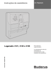
7 747 010 720-01.2RS
Fig. 1
1
2
3
4
5
6
7
8
9
10
11
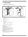
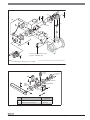
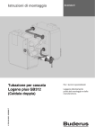
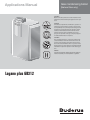
Logano plus GB312 - main components
Programmer (MC10 and BC10)
Gas burner
Boiler front panel
Trap
Boiler heat exchanger with insulation
Burner control unit
Gas valve
Boiler outer casing
B-kit with flow check valve (supplied as standard, not factory installed)
Gas isolating valve (supplied as standard, not factory
installed)
Mating flange, 2½" (included in B-kit, not factory installed)
#$
)$
( ,
-./0
-(
/01
-$2$
'$
/03
-
/0
-*4
*4
5
6)776
)6
8
)8'5
6
)
-
77/0!
#$
#$$2$
)$$
$
$$
' #$$
$
#$
%
&$
'$
!!"
_
GB312 Applications Manual
2
1
Fig. 2
1
2
3
4
5
6
7
8
9
10
11
12
3
4
12 11 10
5
9
6
8
7
7 747 010 720-85.1RS
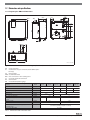
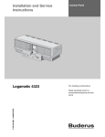
Logamatic BC10 basic programmer - controls
On/off switch
Dial for DHW set point
“DHW heating” LED
Status display screen
Control knob for maximum boiler temperature
“Heat demand” LED
Base plate with slot for a programming unit e.g. RC35 (available : Fall 2008)
(behind the cover panel)
“Burner” LED (ON/OFF)
Socket for connecting diagnostic plug
“Status display” button
“Flue gas test” button
“Reset” button
+!( #$ *
+!
)$$
07)
$$
)'
)$,
-#
$$
5))
-9
$:;<
$2
$
-9
=
7)$
)$+!
)( $)
)$
7
)
$
7'$
$$>+3?
?#$>+3
6'
7
!!"#$
%
&$
'$
_
GB312
Applications Manual
1.1 Package contents
#$
'$+!
+!
@=
76$4$$4
@+$4$4
@:)4
7
AAA
Component
Boiler (fully assembled with outer
casing, Logamatic MC10 programming unit, BC10 and gas isolating
valve)
Technical documentation
Packaging
1 box on a pallet
Set of adjustable feet
1 foil package
1 foil package
B-kit (temperature/pressure gauge,
1 box
pressure relief valve, supply connector,
flow/return mating flange, check
valve)
#$
%
&$
'$
!!"
_
GB312 Applications Manual
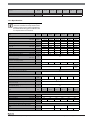
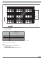
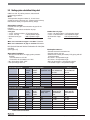
1.2 Dimensions and specifications
1.2.1 Logano plus GB312 dimensions
59¾''
55⅛''
8½''
28¼''
TM
45''
40⅛''
24¼''
8.7''
4 ''
⅝ - 1''
1⅜"
19½''
8½'
RK
7 747 010 720-02.3RS
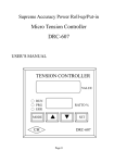
Fig. 3
Connections and dimensions for Logano plus GB312 (sizes in inches)
AA
AL
= Flue connection
= Combustion air pipe connection (balanced flue operation only)
VK = Boiler supply
AKO = Condensate outlet
GAS = Gas connection + main isolating valve
ST
= Pressure relief valve connection
RK = Boiler return
TM = Pressure/temperature gauge
Boiler size (output - no. of heat exchanger
sections)
Model
Width B
Inches
39⅛
Dimension XAA
Inches
13⅛
15⅛
17¼
19¼
Dimension XRK (= XAL = XGAS)
Inches
10⅝
14¾
10⅝
14¾
Dimension F
Inches
31½
Dimension A
Inches
5 1½
AA = Flue pipe diameter
Inches
Flue adaptor for desired manufacturer's flue
system
90 - 4
120 - 4
160 - 5
200 - 6
240 - 7
47⅜
39¾
21⅜
10⅝
48
5 1½
6⅜
8
6 ⅜" x 6 "
6 ⅜" x 5 "
8" x 8 "
Dimension YAA
Inches
1 8½
1 9½
Dimension ZAA
Inches
5¾
12 ¼
AL = Diameter of combustion air pipe (balanced flue only)
Inches
Connections VK and RK
280 - 8
55½
4
(Use rubber plumbing adapter to connect)
2½" NPT
Tab. 1 Dimensions and connection sizes
!!"#$
%
&$
'$
_
GB312
Boiler size (output - no. of heat exchanger
sections)
Model
90 - 4
120 - 4
Connection ST (B-kit)
160 - 5
Applications Manual
200 - 6
240 - 7
280 - 8
¾ " NP T
Diameter GAS
1 " NP T
1 " NP T
1 ¼ " NP T
Tab. 1 Dimensions and connection sizes
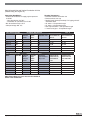
1.2.2 Specifications
Observe all standards and guidelines applicable to the installation and operation of the
heating system in your country. The information on the boiler rating plate is definitive and
it is imperative that it is observed.
Boiler size (output - no. of heat exchanger sections)
Model
90 - 4
120 - 4
160 - 5
200 - 6
240 - 7
280 - 8
Natural gas
I-B-R Input
max. load
Btu/hr
328,300
440,500
588,300
732,600
880,700
1,028,800
min. load
Btu/hr
132,150
132,000
176,000
220,000
264,000
309,000
I-B-R gross output 180/80 ° F
max. load
Btu/hr
305,000
409,000
544,000
676,000
810,000
944,000
I-B-R net rating 180/80 ° F
max. load
Btu/hr
265,000
356,000
473,000
588,000
704,000
821,000
Rated heat input 122/86 ° F
max. load
Btu/hr
307,090
409,460
545,940
682,430
818,910
955,400
(50/30 ° C)
min. load
Btu/hr
128,050
171,190
212,310
255,220
Flue gas mass flow rate 180/80 ° F
max. load
lb/min
4.85
6.53
9.14
11.40
13.88
16.15
Flue gas mass flow rate 122/86 ° F
max. load
lb/min
5.05
7.12
9.29
11.61
14.02
16.65
Flue gas temperature 180/80 ° F
max. load
°F
83
90
127
138
140
134
Flue gas temperature 122/86 ° F
CO2 content, natural gas
max. load
max. load
°F
120
133
129
131
131
135
min. load
Available flue pressure
(flue draft + air supply pressure)
Air supply volumetric flow rate
127,390
fm
%
9.1
in. W.C.
0.4 (100 Pa)
cfm
95
95
130
Blower
160
298,140
190
220
G1G 170
Honeywell gas valve
V4730C1071
V4730C10
63
V4730C1097
Gas injector diameter
Natural gas calorific value 1075 BTU/ft3
17.0
mm
Heating water circuit
Boiler water capacity
US gallons
Primary pressure drop
psi
Maximum flow temperature, heating/hot water
mode (at full output)
°F
180/180
High temperature cut-out safety limit (manual
reset high limit setting )
°F
200
4.2
4.2
5.3
6.3
7.1
7.9
240 - 7
280 - 8
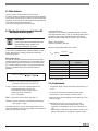
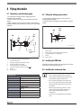
Fig. 4 (graph)
Boiler size (output - no. of heat exchanger sections)
Unit
Permissible operating pressure
psi
50
V/Hz
120 V / 60 Hz
90 - 4
120 - 4
160 - 5
200 - 6
Electrical data
Enclosure class
IP 40
Mains power supply
Power consumption
max. load
W
84
150
190
230
270
370
min. load
W
40
40
45
50
50
50
Maximum permissible fuse rating
A
10 (slow blow)
Appliance dimensions and weight
Transport clearance dimensions, width x depth x
height
Weight
Inches
34x25x60
lbs
455
42x25x60
530
50x25x60
585
665
730
Tab. 2 Specifications
#$
%
&$
'$
!!"
_
GB312 Applications Manual
100
90-4
10
120-4
160-5
200-6
240-7
1
280-8
y
0,1
1
10
100
1000
x
7 747 010 720-30.1RS
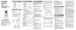
Fig. 4
x
y
Primary circuit flow resistance, GB312 with check valve
Flow rate in gal/min (GPM)
Primary pressure drop in psi
Boiler rating
Gas flow rate
Natural gas
Calorific value 1075 BTU/ft
3
cu ft/hr
90 - 4
120 - 4
3 2 4 .6
434.4
160 - 5
5 7 9 .0
200 - 6
720.6
720.6
240 - 7
8 6 8 .8
280 - 8
1013.4
Tab. 3 Gas flow rate (based on gas temperature of 60 °F and air pressure of 30 in. Hg)
The boiler is factory-set for: – Natural gas
Note:
• #$)
7).
J.
• #$
%%47
7
$.
!!"#$
%
&$
'$
_
GB312
Applications Manual
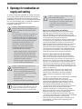
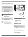
2 Installing the boiler
2.1 Recommended wall clearances
<$
$
6$
)
$8
$
7( " 9
3 6 +
$ 8
'
Dimension
A
B 1)
C
D
E 1)
Wall clearance (inch)
Recomminimum
mended
20
28
28
22
20
28
20
28
6
14
D
E
B
Tab. 4 Recommended and minimum wall clearances
(dimensions in inches). It is imperative that the
minimum clearance (dimension E) is maintained.
C
A
1) This clearance dimension is dependent on the flue system fitted
Where applicable, allow extra wall clearances
for additional components such as DHW
tank, pipe connections or other flue
components, etc.
7 747 010 720-09.1RS
Fig. 5
Wall clearances in the boiler room
Notes: (multiple boiler installations)
A. '
@>)K:L
)
@>)KL
MNM
)44
B.
9#O)$
#$
%
&$
'$
!!"
_
GB312 Applications Manual
2.2 Leveling the boiler
#7
$
'$
))$
6$
7 Caution: Risk of boiler damage due to inadequate load-bearing capacity of floor or unsuitable base.
• Make sure that the surface on which the
boiler stands has sufficient load-bearing
capacity.
• The boiler may stand on a base made of
combustible material but not on carpet.
• Place the boiler in its final position.
• Level the boiler horizontally by turning the adjustable
feet and using a spirit level.
7 747 010 720-10.1RS
Fig. 6 Leveling the boiler
1
2
Adjustable feet
Spirit level
!!"#$
%
&$
'$
_
GB312
Applications Manual
3 Water quality requirements
.'J
$
)
About this chapter:
#$P
)
$
)')
#$
$'$'4)'
02
'$$)
2$'
4$
$%
4
$
)$$
#$P
)$'
J%$
6'$-)$
2
-4
'$$
3.2 Prevention of damage by corrosion
Additional protection against corrosion
+
)2
$
$
'6)26,
-
S2
7
-)2
7
-
*7
0)$
6
*
$
)$2$
Warranty claims in respect of GB312 boilers are
only valid in conjunction with the requirements
specified herein and properly completed annual
service records in the operator’s log and the
servicing and maintenance log.
USER NOTE
• If the appliance is installed in an existing
heating system, dirt may accumulate in the
boiler, leading to localized overheating,
corrosion and noise.
• Alway install a WYE-STRAINER in
existing heating systems.
3.1 Maintenance of user manual
0
$J
)%*%
$
'
$6$
Q++=R
$
$
493
0
4
<TN*
7J #$
$$
$7
)$6
'
$
$'
$
)$6
7
7
Pump
PK
Fig. 7 WYE Strainer location
1
#$
%
&$
'$
WYE Strainer
!!"
_
GB312 Applications Manual
3.3 Water hardness
U
'%$
0
$
7
7)
*)
6$
)*)
$%*%
$
'
$$
3.4 Checking the maximum quantity of first-fill
water based on water quality
USER NOTE
If the system capacity exceeds the calculated allowable water volume Vmax,
damage to the boiler can result.
#$4$'J
'
J6$$)'
$
$$
N2
,
+
)$2J
)%*%
$
'6V26)$
'$
)"336O!!5$S1!-1
<$
%J
++=
Z=W"336O!!5$
;
++!W1!
2'7V2
Vmax = 0.0243 x
Calculation basis
#$%*%
$
'$
J
$
$
$
7)'
$$
*
U$)'
)$2
J
)%'$
'$
,
Vmax (ft3)= 0.0243 ×
QOut
CaCO3
280 ppm
Boiler size
(Btu/h)
(ppm)
Tab. 5
Formula for calculating the maximum quantity of
(untreated) water that may be introduced
955,400 Btu/h
= 83 ft3
Boiler output Qout [Btu/h]
122/86°F
90-4
307,090
120-4
409,460
160-5
545,940
200-6
682,430
240-7
818,910
280-8
955,400
Boiler output
3.5 pH requirements
V2W27)
%*%
$
'
)X$
$7$
7))$
)XWY O1
@#$
);)$)Y !
1 3
Z=W#
5$# @('7$'
$
$2$
++=W+
$
W5
0
)
$
++=6$*
)$
'
)'
@;$4
$
4$'
7
@&
;))
Y !;1 3;
*($'$)$
'6
$
)
$
$4; =>
*>$.4"$7)
).4"3
)7 !!"#$
%
&$
'$
_
GB312
Applications Manual
Vmax [gallon]
Limit curves
7
6$V2%
4
)$)'
$
2000
1900
1800
1700
1600
1500
1400
1300
1200
1100
1000
900
800
700
600
500
400
300
200
100
0
0
50
100
150
200
250
300
350
hardness (CaCO3) [ppm] or [mg/l]
Fig. 2
400
450
500
550
7 747 010 722-01.1RS
Water treatment limit curv es for the various boiler sizes
The rule for V max is:
Above the limit curve = water treatment necessary
Below the limit curve = no water treatment necessary
(Units: 1ft 3 = 7.48 gallon, 1ppm = 1mg/l, 1 grain/gal = 17.1 pm or mg/l)
USER NOTE
Any additives introduced into the heating
system water must be approved by the
manufacturer for use with aluminum boilers.
When is water treatment necessary?
@0)$J
)%'
$
V26
'
@0)$J
)%'
$
V26'
@#$
)6$'77
+
>$>$
$
)S #$
$
)
$%'
3!g
h!g7
@:
')
2$
2$
)
'
#$
%
&$
'$
!!"
_
GB312 Applications Manual
3.6 Operator’s log
Details of GB312 heating system: _________________________________________________________________
Date commissioned:__________________________________________________________________________
Max. water volume Vmax: __________ gal at CaCO3 concentration of ___________ ppm
Anti freeze product used?
Date
Rhomar Rho Gard (50-60% Concentration):
Water volume
unthreated
(measured)
gal
Noble Company Noburst AL (50% Concentration):
CaCO3Total
Concentration of anticoncentrati- water volume
freeze in system %
on ppm
unthreated
gal
Company
(stamp)
Signature
Total fill water
in gal
Added water
in gal
!!"#$
%
&$
'$
_
GB312
Applications Manual
4 Openings for combustion air
supply and venting
#
J
7
)$$
64
'$$
(+6(.3O
90i 69
3 6)+
V
*
6$
0
+
$
'$+5+9O" 0
+ Caution: Risk of boiler damage and malfunctions due to missing or inadequate openings for combustion air and venting of the
boiler room.
The openings for combustion air supply and
venting are always required regardless of
whether the combustion air is drawn from the
room (conventional flue) or supplied directly
to the boiler through ducts (balanced flue).
Inadequate venting of the boiler room
may result in excessive ambient temperatures. This can damage the boiler.
Inadequate combustion air supply may
cause malfunctions in operation.
• Make sure that air inlet or outlet vents are
not closed off or their size reduced and
that they are adequately dimensioned.
• The boiler must not be operated until the
obstruction has been removed.
• Draw the operator's attention to any deficiencies and the potential dangers.
Caution: Risk of boiler damage from contaminated combustion air.
• Never use cleaning agents that contain
chlorine or halogenated hydrocarbons
(e.g. in spray cans, solvents and cleaning
agents, paints, glues).
• Do not store or use such substances in
the boiler room.
• Avoid excessive dust accumulation.
If impurities in the combustion air are possible (e.g. installation near swimming pools, dry
cleaners or hairdressing salons), operation
independent of room air is recommended.
#$
%
&$
'$
Caution: Dangers posed by explosive and
easily combustible materials.
• Do not use or store easily combustible materials (paper, lace curtains, clothing, thinners, paints, etc.) near the boiler.
• Maintain a clearance of 16 inches from the
boiler.
Overall air supply within the building
4$$$'
7
$
$
<$
$*
)$7
6$
)*%
$
4
N$7
$7
*
)
J
$!!!5$)$
)*%
$
4$$*
)$7
!!J
$ =
)$7
$
L)$
$$
$
L)$8)$6)$
)$7
#$
)
7
$
L
Total air supply from outside the building
4$$$'
7
6
)'$$
$
L)$
$$
$
L)$8)
$6)$)$7
#$7
$
7$$$7
*
$
')
#$
)
7
$
L
-0)$
$6$
$7
*
)
J
$O!!!5$)$
)*%
$
-0)$
$$$7
'$77
6$7
$7
*
)
J
$O!!!5$)$
)*%
$ #$
7
$
)$$
-0)$
$$$$S
7
6$7
$7
*
)
J
$!!!
5$)$
)*%
$ #$
$
$))$
-0)$
$$$7
7
'6$
$7
*
)
J
$
O!!!5$ #$7
$
)$$
!!"
_
GB312 Applications Manual
5 Venting requirements
#$$$'
$ #$,
-N2$
-;
-+
$)
-4
$
General notes
#$J87)+
0V
67j90i 5
+9O " #$
)h"*O+
)UY1U!
0
+
68
)U+*hh
<
)$)'
),
6WDLQOHVVVWHHOȺXHV\VWHPIRU86$DQG&DQDGD7DEOH
Manufacturer
Flue System
Heatfab
Saf-T Vent EZ Seal
AL29-4C Starter Adapter Part No.
GB312/90 to GB312/160 = 9601GB ADAPTER (6" nominal size)
GB312/200 to GB312/280 = 9801GB ADAPTER (8" nominal size)
Z-Flex
Z-Vent IV special gas vent
GB312/90 to GB312/160 = 2SVSGBA06 (6" nominal size)
GB312/200 to GB312/280 = 2SVSGBA08 (8" nominal size)
Metal Fab
Corr Gaurd
GB312/90 to GB312/160 = 6CFGBA (6" nominal size)
GB312/200 to GB312/280 = 8CFGBA (8" nominal size)
Pro-Tech
Fasnseal
Security Chimney
CI-System
GB312/90 to GB312/160 = FSA-GB312-6 (6" nominal size)
GB312/200 to GB312/280 = FSA-GB312-8 (8" nominal size)
GB312/90 to GB312/160 = tbd (6" nominal size)
GB312/200 to GB312/280 = tbd (8" nominal size)
&39&ȺXHV\VWHPIRU86$RQO\7DEOH
CPVC Manufacturer
Specification
Manufacturer
CPVC Starter Adapter Part No.
Spears
CPVC pipe to
Heatfab
GB312/90 to GB312/160 = 96GBCPVC ADAPTER (6" nominal size)
Schedule 80 ASTM D1784
GB312/200 to GB312/280 = 98GBCPVC ADAPTER (8" nominal size)
Z-Flex
GB312/90 to GB312/160 = 2SVSGBP06 (6" nominal size)
GB312/200 to GB312/280 = 2SVSGBP08 (8" nominal size)
Metal Fab
GB312/90 to GB312/160 = 6CGBPA (6" nominal size)
GB312/200 to GB312/280 = 8CGBPA (8" nominal size)
Pro-Tech
GB312/90 to GB312/160 = FSA-GB312-6-PVCF (6" nominal size)
GB312/200 to GB312/280 = FSA-GB312-8-PVCF (8" nominal size)
Security Chimney
GB312/90 to GB312/160 = tbd (6" nominal size)
GB312/200 to GB312/280 = tbd (8" nominal size)
Note:.
$
)7 0)+.V+
+
6
7K;7
LU+9hh
#$
6$7
$7
%$8
)
=
6$76$76
$
) #$)'
87)
+
,
&39&ȺXHV\VWHPIRU&DQDGD7DEOH
Manufacturer
Flue System
IPEX*
System 636 CPVC
* This system is only available up to 4" size & only
applies to GB312/90 for 55ft TEL or the GB312/120 for
30ft TEL.
!!"#$
%
&$
'$
_
GB312
(5
'$.
!6V
)NJ
6)$
(+
(.3O90i 6+9 O"$
#$8
)
)
9
3 3 )2 )! O!
$< + !!.)$
72$
=7$)'
'$
$8
,
-#$*
)$8
$
-9$$)$2$
-0
8'$
')$
kL)
<
$%
)7
$8
()
6
$7
)
7
S
)$7
All instructions relating to all parts of the flue
system, and especially the instructions of the
flue system manufacturer, must be followed.
Use only flue pipes with the appropriate diameter for the output rating of the boiler and
made by the recommended manufacturers
listed in Table 6, 7 or 8.
Flue system for multi-boiler systems (cascading
systems)
#$
*
(5)*
J%$
7
$8
) #$8
7
4*8')8$$
$
In the case of exhaust systems sealed with silicon
from a cartridge, the slilicon must be allowed
to cure for 24 hours before commissioning the
boiler.
Danger: Risk of fatal injury from escaping
flue gases in the boiler room.
• The seal in the condensate pan flue connection must be present, undamaged and
correctly inserted.
• Fitting a barometric damper in the flue
system is not permitted.
#$
%
&$
'$
Applications Manual
Caution: Risk of system damage due to inadequate condensate drainage.
• The condensate that forms in the flue pipe
must be drained away from the boiler via
the condensate drain on the condensate
pan.
• Always use a condensate neutralizer.
• Provide periodic maintenance to the
condensate drain piping and neutralizer
system to ensure proper operation.
Caution: Risk of system damage due to inadequate condensate drainage.
• In high temperature applications it
is necessary to use mineral oil in
the condensate trap to maintain a
.trap seal so CO gases do not
escape into the boiler room.
Caution: Disruption of operation due to high
wind.
If no T-piece or 90° downward-turned elbow is
fitted on the end of flue pipe, high winds may
cause the boiler to shut down.
• Always make sure that there is a T-piece
or a 90° downward-turned elbow fitted
depending on the design of the flue system.
• Use only a T-piece or 90° downward-turned
elbow Category IV) made by the selected flue
system manufacturer.
With regard to possible restrictions and inspections for flue systems, consult the local
building and fire safety authorities. Observe
the national regulations.
In the Commonwealth of Massachusetts the
legal requirements concerning the installation
and maintenance of carbon monoxide detectors
must be followed.
Danger: Risk of fatal injury due to poisoning
by escaping flue gas.
• After carrying out any of the installation instructions referred to, check that all connections throughout the entire flue system
are properly joined and sealed.
• Check seams and joints for leaks.
• Have the entire flue system checked once
a year by a qualified heating contractor.
!!"
_
GB312 Applications Manual
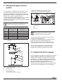
5.1 Connecting the air supply (for direct vent
operations)
#$
$$$$
2
'
6$$$
8
$$
$$
8 (
8
6
).V++.V+67
S
#$8
)
)8
9
h6 ) 2
)! O!
$< + )$72$
We recommend that the air supply pipe
diameter matches the flue pipe diameter.
Boiler rating
Required air supply
volumetric flow rate
Recommended air supply
pipe diameter
[ft 3/min]
[inches]
90 - 4
95
5
120 - 4
95
6
160 - 5
130
6
200 - 6
160
8
240 - 7
190
8
280 - 8
220
8
Tab.9
10 Min
3 Min
Fig. 10 Connecting the air supply for balanced flue
operation
1
2
Screw
Cover plate
Use a 90° elbow for the combustion air inlet
at the entrance to the boiler to avoid an
interference with the gas connection.
Air supply volumetric flow rate/Air supply pipe
diameter
@+
$"!l'$4
$$$
@+
$
$
J
@)4
$
$6
S$'
#"2
<
$%
)7
$
()
6
$
)
1
2 Min
@>7$
)
7
@U
'$7)$
2
48"Max
5.2 Installing the wall exit for air supply pipe
3
3
4
#7
)2$6$2$
4
)))$$
7
'
6
S
6$%
)$6 $
)$8
*
$
)$
*
))
#$
( ( h
$
$
J)%
7 747 010 720-14.2RS
Fig. 9
1
2
3
4
Vertical flue system
Roof penetration
Fire protection collar
Fastening the flue pipe
Flue pipe adaptor (available separately)
!!"#$
%
&$
'$
_
5
GB312
1
Applications Manual
6
2
Contact vent pipe manufacturer for
installation guidelines to support vertical
lengths of pipe.
2
3
4
12 min
Fig. 11 Design of air supply or exhaust pipe wall exit
1
2
3
4
5
6
Outer wall retaining plate
Sealant
T-piece or 4) 90° elbow
90° elbow - down turned
Inner wall centering and retaining plate
Tee termination (optional)
Note: (2$
6$
)
>)(.3O90
i )
5.3 Installing the roof exit for air pipe
#7
)86$8
4
)))$$7
'
6
S
6$%)
$6 $
)$8
$
)$
))
#$
$
$
J)%
B
3
2
1
4 min
A
4 min
7 747 010 720-16.3
Fig. 12 Design of air pipe roof exit
1
3
B
T-piece or 2) 90° elbow
Flue outlet
Minimum horizontal distance from air intake of another
appliance = 10 ft, minimum distance from own air intake
for directly vented appliances = 4 ft.
#$
%
&$
'$
!!"
_
GB312 Applications Manual
5.4 Design of flue and air pipe for balanced flue
operation (refer to NFPA54 ANSIZ223.1 for
l
dimensions)
1
2
1
1
1
1
1
4
2
3
2
3
7 747 010 720-17.2RS
7 747 010 720-19.2RS
Fig. 13 Wall-exit air supply pipe, roof-exit exhaust
Fig. 15 Roof-exit air supply pipe and exhaust
1
1
2
3
4
Flue outlet (type of outlet depends on chosen manufacturer, e.g. 90° elbow or T-piece) See Fig. 9.
Air inlet (T-piece fitted horizontally or 90° elbow)
External wall
Roof
2
3
Flue outlet (type of outlet depends on chosen manufacturer, e.g. 90° elbow or T-piece), observe clearances
specified in Fig. 5
Air inlet terminal (90° elbow pointing away from flue outlet)
Roof
1
2
H
2
2
4
3
1
4
1
3
7 747 010 720-20.2RS
Fig. 14 Wall-exit air supply pipe and exhaust
1;2
3
4
H
Flue outlet (external-wall flue requires horizontally or vertically mounted T-piece), observe clearances specified in
Fig. 11
Air intake terminal (90° elbow facing vertically downwards)
External wall
Refer to NFPA54, ANSIZ223.1 National Fuel Gas Code for
details
7 747 010 720-21.2RS
Fig. 16 Roof-exit air supply pipe, wall-exit exhaust
1
2
3
4
Flue outlet (external-wall flue requires horizontally
mounted T-piece or 90° elbow facing downwards)
Air inlet (90° elbow or T-piece)
External wall
Roof
!!"#$
%
&$
'$
_
GB312
Applications Manual
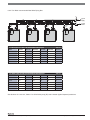
5.5 Venting system calculation/sizing chart
+ 0V76
)
Note:
#J7
$
!6
))
.
$
))%$
Calculation example
+$7
)$
)'
,
V7
7
vent pipe:
@$*"!'WY)J7
$
@$*
W!)J7
$
@h1
))Wh1)J7
$
@#W13)J7
$
combustion air pipe:
@$*"!'W)J7
$
@$*
W!)J7
$
@3!
))W3!)J7
$
@#W1)J7
$
What size vent (exhaust) pipe is needed? 3M
What size combustion air pipe is needed? 3M
5.5.1 VV
V+
0
*
9(3
Operating Conditions:
@#8m
,
! O!M<+
*V
! M<+
*+
! M<+
@
94#,3!(
@+=
,,"g
Venting Parameters:
@N2$$S
,
@N2$7,
@9+ 0
4,.V+
'$"!l
'
''
@"!l'WY)J7
$
@O3l'WO)J7
$
@>
W!)J7
$
@
))W)J7
$
GB312 Venting System TableVent (Exhaust) Outlet Vertical 7DEOH
Models
Input (MBH)
Vent
Connection
at Boiler
Venting
Diameter
(inches)
Total Equivalent
Length of Vent (max)
Vent Diameter for (minus
one) size diameter and
TEL in feet
Vent Diameter for (minus
two) size diameter and
TEL in feet
GB312-90
328
6"
6"
100
5" = 100ft
4" = 55ft
GB312-120
440
6"
6"
100
5" = 80ft
4" = 30ft
GB312-160
588
6"
6"
100
5" = 50ft
4" = NA
GB312-200
733
8"
8"
100
7" = 100ft
6" = 70ft
GB312-240
881
8"
8"
100
7" = 100ft
6" = 55ft
GB312-280
1029
8"
8"
100
7" = 100ft
6" = 35ft
GB312 Venting System TableCombustion Air (inlet) Vertical Models
Input (MBH)
Combustion
Air Inlet
Connection
at Boiler
Combustion
Air Pipe
Diameter
(inches)
Total Equivalent
Length of Combustion
Air Pipe (max)
Combustion Air Pipe
Diameter (minus one
inch) maximum TEL
in feet
Combustion Air Pipe
Diameter (minus two
inch) maximum TEL in
feet
GB312-90
328
4"
5"
100
4" = 55ft
3" = NA
GB312-120
440
4"
6"
100
5" = 95ft
4" = 30ft
GB312-160
588
4"
6"
100
5" = 50ft
4" = NA
GB312-200
733
4"
8"
100
7" = 100ft
6" = 70ft
GB312-240
881
4"
8"
100
7" = 100ft
6" = 55ft
GB312-280
1029
4"
8"
100
7" = 100ft
6" = 35ft
Note: Breeching pressure measured at outlet of
boiler vent connection.
#$
%
&$
'$
!!"
_
GB312 Applications Manual
5.5.2 VV
;S
+
0
9(
Operating Conditions:
@#8m
,
! O!M<+
*V
! M<+
*+
! M<+
@
94#,3!(
@+=
,,"g
Venting Parameters:
@N2$$S
,
@N2$7,
@9+ 0
4,.V+
'$"!l
'
''
@"!l'WY)J7
$
@O3l'WO)J7
$
@>
W!)J7
$
@
))W)J7
$
GB312 Venting System TableVent (Exhaust) Outlet Vertical 7DEOH
Models
Input (MBH)
Vent
Connection
at Boiler
Venting
Diameter
(inches)
Total Equivalent
Length of Vent (max)
Vent Diameter for (minus
one) size diameter and
TEL in feet
Vent Diameter for (minus
two) size diameter and
TEL in feet
GB312-90
328
6"
6"
100
5" = 100ft
4" = 55ft
GB312-120
440
6"
6"
100
5" = 80ft
4" = 30ft
GB312-160
588
6"
6"
100
5" = 50ft
4" = NA
GB312-200
733
8"
8"
100
7" = 100ft
6" = 70ft
GB312-240
881
8"
8"
100
7" = 100ft
6" = 55ft
GB312-280
1029
8"
8"
100
7" = 100ft
6" = 35ft
GB312 Venting System TableCombustion Air (inlet) Horizontal Models
Input (MBH)
Combustion
Air Inlet
Connection
at Boiler
Combustion
Air Pipe
Diameter
(inches)
Total Equivalent
Length of Combustion
Air Pipe (max)
Combustion Air Pipe
Diameter (minus one
inch) maximum TEL
in feet
Combustion Air Pipe
Diameter (minus two
inch) maximum TEL in
feet
GB312-90
328
4"
5"
100
4" = 40ft
3" = NA
GB312-120
440
4"
6"
100
5" = 75ft
4" = NA
GB312-160
588
4"
6"
100
5" = NA
4" = NA
GB312-200
733
4"
8"
100
7" = 100ft
6" = 45ft
GB312-240
881
4"
8"
100
7" = 100ft
6" = NA
GB312-280
1029
4"
8"
100
7" = 100ft
6" = NA
Note: Breeching pressure measured at outlet of
boiler vent connection.
!!"#$
%
&$
'$
_
GB312
Applications Manual
5.5.3 ;S
V
;S
+
0
9(O
Operating Conditions:
@#8m
,
! O!M<+
*V
! M<+
*+
! M<+
@
94#,3!(
@+=
,,"g
Venting Parameters:
@N2$$S
,
@N2$7,
@9+ 0
4,.V+
'$"!l
'
''
@"!l'WY)J7
$
@O3l'WO)J7
$
@>
W!)J7
$
@
))W)J7
$
GB312 Venting System TableVent (Exhaust) Outlet Horizontal 7DEOH
Models
Input (MBH)
Vent
Connection
at Boiler
Venting
Diameter
(inches)
Total Equivalent
Length of Vent (max)
Vent Diameter for (minus
one) size diameter and
TEL in feet
Vent Diameter for (minus
two) size diameter and
TEL in feet
GB312-90
328
6"
6"
100
5" = 100ft
4" = 40ft
GB312-120
440
6"
6"
100
5" = 75ft
4" = NA
GB312-160
588
6"
6"
100
5" = NA
4" = NA
GB312-200
733
8"
8"
100
7" = 100ft
6" = 45ft
GB312-240
881
8"
8"
100
7" = 100ft
6" = NA
GB312-280
1029
8"
8"
100
7" = 65ft
6" = NA
GB312 Venting System TableCombustion Air (inlet) Horizontal Models
Input (MBH)
Combustion
Air Inlet
Connection
at Boiler
Combustion
Air Pipe
Diameter
(inches)
Total Equivalent
Length of Combustion
Air Pipe (max)
Combustion Air Pipe
Diameter (minus one
inch) maximum TEL
in feet
Combustion Air Pipe
Diameter (minus two
inch) maximum TEL in
feet
GB312-90
328
4"
5"
100
4" = 40ft
3" = NA
GB312-120
440
4"
6"
100
5" = 75ft
4" = NA
GB312-160
588
4"
6"
100
5" = NA
4" = NA
GB312-200
733
4"
8"
100
7" = 100ft
6" = 45ft
GB312-240
881
4"
8"
100
7" = 100ft
6" = NA
GB312-280
1029
4"
8"
100
7" = 65ft
6" = NA
Note: Breeching pressure measured at outlet of
boiler vent connection
#$
%
&$
'$
!!"
_
GB312 Applications Manual
5.5.3 ;S
V
V+
0
9(h
Operating Conditions:
@#8m
,
! O!M<+
*V
! M<+
*+
! M<+
@
94#,3!(
@+=
,,"g
Venting Parameters:
@N2$$S
,
@N2$7,
@9+ 0
4,.V+
'$"!l
'
''
@"!l'WY)J7
$
@O3l'WO)J7
$
@>
W!)J7
$
@
))W)J7
$
GB312 Venting System TableVent (Exhaust) Outlet Horizontal 7DEOH
Models
Input (MBH)
Vent
Connection
at Boiler
Venting
Diameter
(inches)
Total Equivalent
Length of Vent (max)
Vent Diameter for (minus
one) size diameter and
TEL in feet
Vent Diameter for (minus
two) size diameter and
TEL in feet
GB312-90
328
6"
6"
100
5" = 100ft
4" = 40ft
GB312-120
440
6"
6"
100
5" = 75ft
4" = NA
GB312-160
588
6"
6"
100
5" = NA
4" = NA
GB312-200
733
8"
8"
100
7" = 100ft
6" = 45ft
GB312-240
881
8"
8"
100
7" = 100ft
6" = NA
GB312-280
1029
8"
8"
100
7" = 65ft
6" = NA
GB312 Venting System TableCombustion Air (inlet) Vertical Models
Input (MBH)
Combustion
Air Inlet
Connection
at Boiler
Combustion
Air Pipe
Diameter
(inches)
Total Equivalent
Length of Combustion
Air Pipe (max)
Combustion Air Pipe
Diameter (minus one
inch) maximum TEL
in feet
Combustion Air Pipe
Diameter (minus two
inch) maximum TEL in
feet
GB312-90
328
4"
5"
100
4" = 55ft
3" = NA
GB312-120
440
4"
6"
100
5" = 95ft
4" = 30ft
GB312-160
588
4"
6"
100
5" = 50ft
4" = NA
GB312-200
733
4"
8"
100
7" = 100ft
6" = 70ft
GB312-240
881
4"
8"
100
7" = 100ft
6" = 55ft
GB312-280
1029
4"
8"
100
7" = 65ft
6" = 35ft
Note: Breeching pressure measured at outlet of
boiler vent connection
!!"#$
%
&$
'$
_
GB312
Applications Manual
6 Piping the boiler
6.1 Connecting central heating supply
6.2 Fitting the heating system return
@(
$$
$
$8
@0
$
$8
&
$
$
7
@'
7
$$477
&
'$
)
@(
$$
$
$8
@0
$
$8
&
$
$
7
2½"
NPT
RK
VK
1
5
2½"
NPT
4
1
4
3
2
7 747 010 720-81.1RS
Fig. 18 Fitting the return pipe
6
3
2
Note:
Flow Direction
Arrow
7 747 010 720-04.1RS
1
2
3
4
RK
Boiler return
Return pipe (external with NPT male thread)
Threaded flange - 2½" NPT female
Gasket
Boiler return
Fig. 17 Fitting the B-kit and supply pipe
1
2
3
4
5
6
VK
Pressure relief valve
Supply pipe (external with NPT thread)
Pressure/temperature gauge
Threaded flange - 2½" NPT female
Check valve (observe direction of flow
Gasket
Boiler supply
6.3 Installing the DHW Tank
:;<#
4$S
)$ 9
'
$ )
%.LW3DUWVOLVW
Quantity
Description
1
Supply Manifold
4
2½" Pipe Size Gaskets
1
Check Valve
1
Pressure and Temperature Gauge
1
Relief Valve - 50psi
12
Nuts - "
8
Bolts - " x 2½" L
4
Bolts - " x 5" L
24
Washers - "
12
Lock Washers
6.4 Installing the condensate drain
Notes on condensate drainage.
• The condensate that forms in the boiler
and possible in the flue pipe must be properly drained away from the boiler.
• The condensate which forms in the flue
pipe can be drained via the boiler (install
flue pipe with downward slope towards
the boiler).
• Make sure that drainage of the condensate into the public sewer system conforms with the applicable national
regulations.
• Also observe any applicable local regulations.
#$
%
&$
'$
!!"
_
GB312 Applications Manual
@>7$
@U
'$
%$'$2 ! )' Note: For high temperature applications add 1 cup
of mineral oil to the trap
2
Danger: Risk of fatal injury from poisoning.
If the trap is not filled with water or other connections are left open, escaping flue gas can
place lives at risk.
• Fill the trap with water. (or mineral oil on
high temperature applications)
• Seal the trap and flue connections.
• Make sure that the washer and seal are
properly seated in the cap.
1
5
6
4
@$$ 3
Condensate may possibly escape through
the trap vent hole.
• Be sure to run the drain pipe from the trap
so that it slopes downwards.
Danger: Risk of fatal injury from poisoning.
• The boiler's internal trap must be used,
make sure that the condensate from the
flue system drains correctly.
A condensate neutralizer is available as an
accessory. (Buderus part no. - NE0.1)
• Install the neutralizer according to the installation instructions.
• Fit the trap supplied to the condensate
pan drain outlet.
1
7 747 010 720-23.1RS
Fig. 19 Installing the condensate drain
1
2
3
4
5
6
Trap
Condensate pan
Trap outlet to neutralizer/waste pipe
Trap vent
Blanking cap
Hole for condensate drain hose
6.5 Connecting the fuel supply
Danger: Risk of fatal injury from the explosion of flammable gases.
• Work on gas components may only be
carried out by qualified and authorized
personnel.
6.5.1 Installing gas supply piping
()$J6)
#
$)'
4
$$%
$7$$S
@4$
%$
)
$$ !!"#$
%
&$
'$
_
GB312
Fit and seal the gas isolating valve supplied
to the boiler's gas connection.
@#$)
$
=7$
$J
$
(+690i +5+9
O" +
6'$
$
<$J
6$
'$$
+)+
9)
:7)(9N+9:*
'$9N+9:*7 Length
of pipe
in feet
10
20
30
40
50
75
100
150
Applications Manual
Gas pipe delivery rate in cubic feet of
gas per hour 1)
1"
1¼"
1½"
2"
2½"
520
1060
1600
3050
4800
350
730
1100
2100
3300
285
590
890
1650
2700
245
500
760
1450
2300
215
440
670
1270
2000
175
360
545
1020
1650
160
305
480
870
1400
120
250
380
710
1130
Tab. 14 Gas pipe delivery rate
1
1) Maximum gas pipe delivery rate in cu ft/hr based on a gas specific gravity of 0.60 and a gas pressure of 0.5 psi or less and a
pressure drop equivalent to a water column of 0.3 inches.
4
Iron pipe
nominal
diameter (in
inches)
2
1
1¼
1½
2
2½
3
Equivalent lengths for pipe fittings
in feet
Pipe fitting type
90°
T-piece
Shutoff
Gas
elbow
valve
cock
Equivalent lengths in feet
3
5
0.6
1.60
4
6
0.8
2.15
5
7
1.0
2.50
7
10
1.3
3.00
8
12
1.6
3.50
Tab. 15 Equivalent lengths for pipe fittings
7 747 010 720-22.1RS
Fig. 20 Gas valve pipe connection
1
2
3
4
Gas supply
Manual shut-off valve (supplied)
Sediment trap
Gas connection with isolating valve
:
$
77)$
)$&
'$$$
2n
0)$
&
'$$$
n6
)%
$)$
$7
77
@#$
)4
)
U
$
)
$
#$
$2
$)$
#$
%
&$
'$
!!"
_
GB312 Applications Manual
6.6 Pipe Sizing
(
69
h h h #$
.
9S
"A"
"B"
"C"
Pump
PK
Pump
PK
Pump
PK
7KUHHGB312 System (18°F Delta T) Recommended Near Boiler Piping Size 7DEOH
Models
GB312/90
Pipe A
2½"
Pipe B
2"
Pipe C
1½"
Header E
2½"
GB312/120
System
Supply
"A"
"B"
"C"
GB312/160
GB312/200
GB312/240
GB312/280
3"
4"
4"
4"
4"
2½"
3"
3"
4"
4"
2"
2½"
2½"
2½"
3"
3"
4"
4"
4"
4"
7KUHHGB312 System (36°F Delta T) Recommended Near Boiler Piping Size 7DEOH
Models
GB312/90
GB312/120
GB312/160
GB312/200
GB312/240
GB312/280
Pipe A
2"
2½"
2½"
3"
3"
4"
Pipe B
1½"
2"
2"
2½"
2½"
3"
Pipe C
1¼"
1½"
1½"
2"
2"
2½"
Header E
2"
2½"
2½"
3"
3"
4"
System
Return
"E"
99
! ! 6#Y!)
.o
;;*9
!!"#$
%
&$
'$
_
GB312
Applications Manual
h h (
.
9S
"C"
"D"
"B"
"C"
"D"
Pump
PK
Pump
PK
Pump
PK
"A"
Pump
PK
)RXUGB312 System (18°F Delta T) Recommended Near Boiler Piping Size 7DEOH
Models
GB312/90
GB312/120
GB312/160
GB312/200
GB312/240
GB312/280
Pipe A
3"
4"
4"
4"
5"
6"
Pipe B
2½"
3"
4"
4"
4"
4"
Pipe C
2"
2½"
3"
3"
4"
4"
Pipe D
1½"
2"
2½"
2½"
3"
3"
Header E
3"
4"
4"
4"
5"
6"
)RXUGB312 System (36°F Delta T) Recommended Near Boiler Piping Size 7DEOH
Models
GB312/90
GB312/120
GB312/160
GB312/200
GB312/240
GB312/280
Pipe A
2½"
3"
3""
4"
4"
4"
Pipe B
2"
2½"
2½"
3"
3"
4"
Pipe C
2"
2"
2½"
2½"
2½"
3"
Pipe D
1½"
1½"
2"
2"
2"
2½"
Header E
2½"
3"
3"
4"
4"
4"
System
Supply
"A"
"B"
System
Return
"E"
99
! ! 6#Y!).o
;;*9
#$
%
&$
'$
!!"
_
GB312 Applications Manual
7 CSD-1 Kit
@+$#$$
+ $)
'$; . p . @#$
YYOY!""13)$
@''$
+h!"Y!h
@;$'$
:3+#3<
@''*<+=
;
'$ @.
$)'
,
<+=*33!
;*O!!hN!"
130
140
141
142
143
144
145
150
110
40
100
50
51
10
30
60
60
20
70
80
90
120
High Pressure (H.P.) Switch location
set point = 2"WC Nat. Gas.
30
30
NOTE:
• It works on a zero pressure regulated combination gas valve.
• If the pressure regulator inside the combination gas valve fails,
the H.P. switch will cut-out during burner operation.
7747101925-02-Zuluft, Venturi VM312 US
Fig. 21 Air inlet, venturi GB312 US
!!"#$
%
&$
'$
_
GB312
10
20
60
61
62
100
20
40
50
Applications Manual
20
30
40
50
30
50
40
50
70
40
80
81
Low Pressure (L.P.) Switch location
Setpoint = 3"WC Nat. Gas.
90
91
NOTE:
• The minimum gas supply pressure is 3.5"WC.
Fig. 22
7747101926-02-Gasarmatur VR4730, Gasanschlussrohr VM312 US
Gas valve VR4730, gas connecting pipe GB312 US
Pressure Relief
Valve
50 psig
Mating Flange
2½" NPT female
connection
240
Check Valve
Supply
Connection
at Boiler
Supply Manifold
210
Gasket
(typical)
Item
no.
Description
Buderus
part number
210
Low water cut-off SAFGARD 3/4"M
550
240
High temperature cut-off 3/4"M
L4006E1109
Fig. 23 Boiler Supply Manifold and Controls.
#$
%
&$
'$
!!"
GB312 Applications Manual
_
7.1 Operating Addendum for the GB312 in High
Temperature Applications
02
$$))$
)
#$)
3
#$
$77)$+!
#$
)
=#
#$'
$$
2$
))8''$
9N
+9:$$))$
!!"#$
%
&$
'$
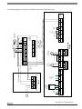
US
IONIZATION
Plug
MV1
M
FAN
PWM-FAN
IGNITOR
MV2
L
N
L
N
L
N
L
N
fan
valve 2
2
valve 1
1
ignition
DUAL VALVE
COMBINATION
Netz SAFe
N L
mains
supply
(SOCKET NOT
USED)
BUS
SAFe
NOTE: Blocked Air Pressure Switch
• GB312/90 to 160 : Off =-1.6"WC
On =-1.48"WC
• GB312/200 to 280: Off =-2.4"WC
On =-2.24"WC
Ionization
PWM
pW
p
FG
FR
• GB312 all models : Off =3"WC
On =2.75"WC
NOTE: Safe Gas Pressure Switch = NG
1
3
black
• GB312 all models : Off =1.6"WC
On =1.48"WC
NOTE: Blocked Vent Pressure Switch
blue
2007/11
brown
black
white
2
white
3
black
2
3
1
1
2
3
4
5
6
7
8
3
2
white
black
white
2
black
Page: 1/1
GB312 USA/CD
BLOCKED VENT
PRESSURE
SWITCH
1
3
BLOCKED AIR
PRESSURE
SWITCH
PRESSURE
CONTROL
SET
NO adjustments necessary or possible on all pressure sensors
WATER
PRESSURE
SENSOR
LOW GAS
PRESSURE
SWITCH
(OPTIONAL)
1
IN CASE OF CONNECTION
REMOVE JUMPER 3-4
3" WC Setpoint
HIGH GAS
PRESSURE
SWITCH
(OPTIONAL)
IN CASE OF CONNECTION
REMOVE JUMPER 5-6
2" WC Setpoint
SAFE GAS
PRESSURE
SWITCH
Wiring diagram :
2
white
7365
Edition :
1
Reviewed :
7747019193
SUPPLY-FLOW
TEMPERATURE
SENSOR
Drwg. no.:
RETURN-FLOW
TEMPERATURE
SENSOR
Boiler Control Unit MC10
SAFe
120V AC
Version
FK
BUS
BOILER-HIGH-LIMIT
TEMPERATURE
SENSOR
Wiring diagram gas-boiler GB312 USA/CD
!!"
#$
%
&$
'$
+
Applications Manual
GB312
_
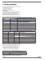
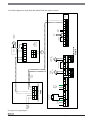
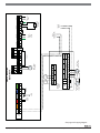
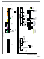
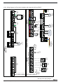
8 Boiler internal wiring diagram
SAFe bus
connection to
burner control unit
Basic controller BC10
EMS bus
connection to
function modules
1) The total current drawn must not exceed 5 A.
AWG18
RC35 control unit
or blank cover
Connection to
room controller
(RC)
AWG18
Replacement fuse 10 A slow
Note!
Installation, circuit breaker, emergency shut-off switch, and all safety
components must comply with local regulations.
Caution! Yellow/green ground conductor must not be used as control lead.
Make sure terminals are connected with correct polarity.
Controller must be hard wired.
Device fuse 10 A slow
Logamatic MC10
Location for Function modules xM10
External lock out
Jumper must be
removed when
connected (EV)
AWG18
AWG18
DHW
temperature
sensor
(FW)
Basic controller BC10
1
Outdoor
Temperature
sensor
(FA)
AWG18
Heat
demand,
external
(WA)
AWG18
Heating system circulation
pump (PH-HK1)
or
DHW
circulation
pump
(PZ)
max. 5A 1)
AWG14
Tank charging
pump (PS)
or
Motorized 3-way
valve
(DWV)
max. 5A 1)
max. 5A 1)
Supply pump
(PZB)
AWG14
AWG14
Mains power
supply, function
modules
120V 60Hz
Mains FM
Mains
120V 60Hz
max. permiss.
fuse rating 10A
Mains
SAFe ................BUS for SAFe burner control unit
EMS..................BUS for function modules
RC ....................Room controller (e.g. RC35)
EV.....................External shut-off contacts
FW....................DHW sensor
FA..................... Outdoor temperature sensor
WA....................Heat demand, external
PZ.....................Supply pump
PH-HK1 ............Heating system pump (circuit 1)
PZ.....................DHW circulation pump
DWV .................Motorized 3-way valve
ON/OFF switch
PS ....................Tank charging pump
Mains FM .........Mains connection for function
Netz ..................Mains connection for Logamatic MC10 programming unit
Sfty devices .....Safety circuit for connecting external devices,
e.g. gas pressure monitor. Triggering disables the burner
control unit.
Mains SAFe..... Mains connection for SAFe burner control unit
Key to abbreviations
max. 5A 1)
AWG14
Mains SAFe
Low voltage
Wiring example
for safety devices
(external)
Basic equipment for
boiler system control
and DHW heating
Mains power supply,
SAFe burner control unit
120V 60Hz
Sfty devices
Fuse
10A slow
Control voltage 120V~
Component 2
Component 1
GB312 Applications Manual
_
9 MC10 wiring diagram
!!"#$
%
&$
'$
powerup
state 12:
check
gas pressure
0,1-5s
state 40:
catch
flame signal
0,1-1s
state 13:
check
safety pressure
0,1-7s
state 55:
stabilize
startload
10s
state 20:
holding tme
Ignition cold
0,1- 4s
state 56:
stabilize
partload
18s
state 23:
turn on
fan
0,1-30s
state 00:
resting state
0,1s - ∞
state 60:
at work
0,1s-23h
state 25:
pre purge
5s
start signal
state 30:
Safeguard
against
extraneous light
5s
state 05:
safety-check
4s
state 31:
wait for
startspeed
0,1-30s
state 10:
turn on
safety-relay
0,5s
-
state 11:
open valve 2
2s
state 35:
main gas valve
3s
state 180:
controlled shut
down
0,5s
state 32:
ignition
3s
state 190:
recycling
10s - ∞
From every
state (with own
error number)
From every
state (with own
error number)
no start signal
state 200:
non-volatile
lock out
0,1s - ∞
!!"
#$
%
&$
'$
Applications Manual
GB312
_
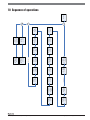
10 Sequence of operations
_
GB312 Applications Manual
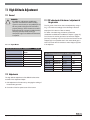
11 High Altitude Adjustment
11.1 General
DANGER:
• If installation, adjustment, modification,
operation or maintenance of the heating
system is carried out by an unqualified person,
this may result in danger to life and limb or
property damage. These instructions must be
followed precisely. Contact a qualified service
company, service provider or the gas
company if support or additional information
is required.
11.1.1 Input Rates
11.3 CO² adjustment of the burner / adjustment of
the gas valve
#$+=¢7)$
$&
+=¢*5+=*
$)'
+=¢7
#'
(
6
£0
P$YO #$+=7
$8$$
!!
) 0)
)" V g+=¢
+=7
!!)
$
6
'+=¢7'$+=
!!)$
&
,QSXWUDWHVIRUHOHYDWLRQVIW$6/7DEOH
Models
Input rate
(Mbtu/hr)
GB312-90
328
GB312-120
441
GB312-160
588
GB312-90
min-/max- load
9.1 / 9.1
<100
GB312-200
733
GB312-120
min-/max- load
9.1 / 9.1
<100
GB312-240
881
GB312-160
min-/max- load
9.1 / 9.1
<100
GB312-280
1029
GB312-200
min-/max- load
9.1 / 9.1
<100
GB312-240
min-/max- load
9.1 / 9.1
<100
GB312-280
min-/max- load
9.1 / 9.1
<100
&2 &2OHYHOVIRUHOHYDWLRQVIW$6/7DEOH
å
Models
CO² (Vol. %)
CO (ppm (af) )
11.2 Adjustments
#$$$&
)$
)'&
+=&
)$
$
$
)
$77
+
)$)
7)$
!!"#$
%
&$
'$
_
GB312
Applications Manual
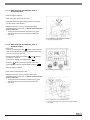
11.3.1 Set BC10 control to “flue gas test”
operation
#$
$$
)$8
#$
$$
8'
)!
:
$86$
$$
$
@.
$$
$$
6
$
$
$8$
)LJ6WDUWLQJWKHÀXHJDVWHVW
11.3.2 Opening the Service menu and viewing
monitor data on the RC35
Menu
• 9
$ OK +
$
Info
+
*4'
• #
$
¤
• .$ Menu
OK $
*4'
• #
$
¤
Menu
• .$ OK $
*4'
• #
$
"#
¤
Menu
• .$ OK $$
#$
6 $'
#$
))$
5
#$
%
&$
'$
!!"
_
GB312 Applications Manual
11.3.3 Adjusting and checking CO² level at
maximum output
•>))
>+3
•<
$Y!g
•0
$
$$
$
$8
$
)$8'
•&$7" g+=¢
$$$*
&
'( 36 %&
"'
*2"
-#
$'4'$+=¢7
-#
$'
*4'
$
+=¢7 )LJ6HWWLQJWKH&2ðDWPD[LPXPRXWSXW
+LJKRXWSXWDGMXVWLQJVFUHZ
11.3.4 Adjusting and checking CO² level at
minimum output
•9!g
$
#6
$$
$$
#$
$8
•9
$$
)2 3
M
$)
6$$'M
•.$ $
M
)2
$$'M
Reset
•>))
>+3
)LJ6HWWLQJPLQLPXPRXWSXW
•<
$!g
•&$7" g+=¢
$'*
&
'( 36 %&
"'
*2"
-#
$'4'
$+=¢7
-#
$'
*4'$
+=¢7
)LJ6HWWLQJWKH&2ðDWPLQLPXPRXWSXW
/RZRXWSXWDGMXVWLQJVFUHZJDVYDOYH+RQH\ZHOO9&
&DSVFUHZ
!!"#$
%
&$
'$
_
GB312
Applications Manual
11.3.5 Check and monitoring CO² level at
maximum output
•.$
$
$$
•>))
>+3
•<
$Y!g
•+$4+=¢
11.3.6 Recording measured values
•#4$)'
$
8
$
$
0
,9
Y !6
3O,
-(
-(
-8
S
-+
2
+=¢2
=¢
-+
2
+=
•+
$8
$
)LJ5HFRUGLQJWKHPHDVXUHGYDOXHV
5HFRPPHQGHGORFDWLRQIRUWHVWLQJSRLQWRQÀXHSLSH
11.4 Settings for speed of burner fan
#$)
7)$
$&
$
)$+!
$
)#)$
4466'6'''
7 .$K+$
'L
K9L
$)3
.$K9L
O
$2)
+!
'$',K !L
.$K>L
$7)
$*
Reset
.$K+$
'L
$7)$
p
.
)
)
3
#$
%
&$
'$
!!"
_
GB312 Applications Manual
#$
$
)$
0
)&
$)
)$$
#'
%&SDUDPHWHUUDQJHIRUIDQDGMXVWPHQWRI*%ERLOHUV7DEOH
Parameter
Input range
Factory setting for sea level
operation
Burner input load
correction: 2
0 to +9
(- setttings lower than 0 will be
ignored by the control)
2.0
=
)2 ! hg
%&SDUDPHWHUVHWWLQJVIRUDGMXVWPHQWRIIDQVSHHG7DEOH
GB312
boiler size
0 - 2000ft
(0 - 610m)
2001 - 4500ft
(611 - 1372m)
4501 - 7000ft
(1373 - 2134m)
7001 - 9500ft
(2135 - 2896m)
9501 - 12000ft
(2897 - 3666m)
90
120
160
2.0
2.1
2.2
2.3
2.4
200
240
280
2.0
2.2
2.4
2.6
2.8
!!"#$
%
&$
'$
_
GB312
Applications Manual
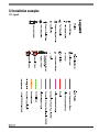
12 Installation examples
12.1 Legend
#$
%
&$
'$
!!"
_
GB312 Applications Manual
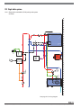
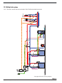
12.2 Single boiler systems
FW
DHW
Sensor
System
Circulator
L4006A
PS
DHW
Loading
Pump
Isolation
Relay
AM10
Single
Zone
Relay
TStat
OTS
PZB
9
'$!6:;<
9OO)'
!!"#$
%
&$
'$
BUS
SAFe
2
White
EMS
1
H
Single Zone
Switching
Relay
N
1
2
Red
EV
24
VAC
1
W
Factory
installed
jumper
R
6
N/C
COM
4
N/C
T
4
N/O
T
T
Stat
2
Orange
RC
3
L4006A
5
DHW
Sensor
2
Grey
FW
1
6
N/O
2
Blue
FA
1
Not used
with AM10
2
Green
WA
1
N/C
61
63
63
Dark Green
PH-HK1
61
Dark Green
PZB
GB312
MC10/BC10
Common
Isolation
Relay
N/O
Not Used
13
Purple
PZ
14
25
74
Purple
DWV
73
24
Gray
PS
Purple
Not used with AM10
75
N
L
Yellow
Netz Module
PS - DHW
Loading
Pump
EMS Bus
Connection
to boiler
Boiler
Circulator
N
White
Netz
Main
Power
115 V
60 Hz
L
1
18
Low water
cut off – dry
contacts
17
Orange
N
2
Red
On/Off
1
2
Blue
OTS
N
Tan
Netz
L
Power to
SAFe
AM10
(Outdoor Reset Module)
2
White
BUS
1
Outdoor
sensor
!!"
#$
%
&$
'$
Applications Manual
GB312
_
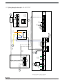
<
)
'$!6:;<
9O)
_
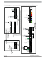
GB312 Applications Manual
AM10
FW
DHW
Sensor
PS
DHW
Loading
Pump
L4006A
System
Circulator
Single
Zone
Relay
TStat
OTS
PZB
9
'$!6:;<
9Oh)'
!!"#$
%
&$
'$
BUS
SAFe
2
2
Orange
RC
1
Red
EV
1
2
2
Grey
FW
1
2
Blue
FA
1
Not used
with AM10
2
Green
WA
1
H
Single Zone
Switching
Relay
N
DWV
13
Not used with AM10
25
PS – DHW
Loading
Pump
24
Gray
PS
74
Purple
5
73
PZB
14
Dark Green
63
63
Purple
61
6
N/O
PZB - Boiler
Circulator
61
Dark Green
24
VAC
PZ
W
PH-HK1
R
6
N/C
COM
4
N/C
T
4
N/O
T
T
Stat
GB312
MC10/BC10
3
L4006A
75
N
L
Yellow
Netz Module
EMS Bus
Connection
to boiler
N
White
Netz
Main
Power
115 V
60 Hz
L
1
18
Low water
cut off – dry
contacts
17
Orange
N
2
Red
On/Off
1
2
Blue
OTS
N
Tan
Netz
L
Power to
SAFe
AM10
(Outdoor Reset Module)
2
White
BUS
1
Outdoor
sensor
!!"
#$
%
&$
'$
White
EMS
1
Factory
installed
jumper
DHW
Sensor
System
Circulator
Applications Manual
GB312
_
O<
)
'$!6:;<
9O3)
_
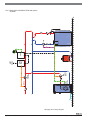
GB312 Applications Manual
Thermostatic
Mixing
Valve
L4006A
High
Temperature
Zone
Low
Temperature
Zone
FW
DHW
Sensor
PS
DHW
Loading
Pump
TStats
Multi
Zone
Relay
AM10
OTS
PZB
39
'$!6:;<
$S
9O1)'
!!"#$
%
&$
'$
BUS
SAFe
2
White
EMS
1
2
Orange
RC
1
Red
EV
1
2
Factory
installed
jumper
2
Grey
FW
1
DHW
Sensor
2
Blue
FA
1
Not used
with AM10
T
Stat
ZC
ZR
L4006A
Zone 1
Zone 2
T
Stat
25
74
DWV
Input
Power
75
N
L
Yellow
Netz Module
EMS Bus
Connection
to boiler
PS – DHW
Loading
pump
24
Gray
PS
73
Purple
Dark Green
Purple
61
Dark Green
13
PZ
63
Zone 4
Not used with AM10
Zone 4
Zone 3
High Temp
Zone Circulator
120 V Circulators
Zone 2
Zone 3
PZB - Boiler
Circulator
61
PH-HK1
63
PZB
14
Dark Green
GB312
MC10/BC10
Zone 1
2
Green
WA
1
Multi Zone
Switching
Relay
End
Switch
Low Temp
Zone Circulator
N
White
Netz
Main
Power
115 V
60 Hz
L
1
18
Low water
cut off – dry
contacts
17
Orange
N
2
Red
On/Off
1
2
Blue
OTS
N
Tan
Netz
L
Power to
SAFe
AM10
(Outdoor Reset Module)
2
White
BUS
1
Outdoor
sensor
!!"
#$
%
&$
'$
Applications Manual
GB312
_
h<
)
'$!6:;<
$S
9OY)
_
GB312 Applications Manual
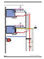
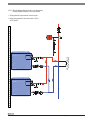
12.3 Multiple boiler systems
PZB
AM10
Multi
Zone
Relay
OTS
TStats
CM10
PZB
System
Flow
Sensor
PH
System
Circulator
PS
DHW
Loading FW
DHW
Pump
Sensor
Thermostatic
Mixing
Valve
L4006A
Low
Temperature
Zone
High
Temperature
Zone
#''$'$6+!6:;<
$S
93!
3)'
!!"#$
%
&$
'$
BUS
SAFe
2
White
EMS
1
N
L
Yellow
Netz Module
Power
from
MC10
2
Orange
RC
1
N
1
L
Red
EV
2
DHW
Sensor
2
Grey
FW
1
61
Brown
PH
63
2
Blue
FA
1
Not used
with AM10
2
Green
WA
1
3
4
14
Blue
13
15
6
25
75
L
Power to
CM10
Module
N
Yellow
Netz Module
EMS Bus
Connection
to boiler #2
EMS Bus
Connection
to boiler #1
PS - DHW
Loading
Pump
24
Gray
PS
74
DWV
13
Not used with AM10
10
Stripe
9
20
Stripe
19
73
Purple
Purple
14
PZB
63
63
8
18
PZ
Dark Green
61
17
Orange
7
White
PZB - Boiler
Circulator
61
PH-HK1
Dark Green
16
White
5
White
GB312 Boiler #1
MC10/BC10
2
Brown
12
Tan
11
1
CM10
(2 Boiler Cascade Module)
Factory
installed
jumper
Yellow
Netz Module
System
Circulator
System
flow sensor
N
White
Netz
Main
Power
115 V
60 Hz
L
1
18
Low water
cut off – dry
contacts
17
Orange
N
2
Red
On/Off
1
2
Blue
OTS
N
Tan
Netz
L
Power to
SAFe
AM10
(Outdoor Reset Module)
2
White
BUS
1
Connection
to end
switch on
Multi Zone
Switching
Relay
Outdoor
sensor
!!"
#$
%
&$
'$
Applications Manual
GB312
_
<
)''$'$6+!6:;<
$S
9O")
BUS
SAFe
2
1
1
2
Orange
RC
White
EMS
1
Factory
installed
jumper
2
Red
EV
1
DHW
Sensor
2
Grey
FW
2
1
2
Green
WA
Low Temp
Zone
Circulator
End
Switch
Multi Zone
Switching
Relay
Not used
with AM10
1
Blue
FA
ZC
ZR
Zone 1
T
Stat
L4006A
Zone 1
Zone 2
T
Stat
Zone 3
Zone 4
14
24
Gray
PS
Input
Power
Not used
Zone 4
13
High Temp
Zone Circulator
120 V Circulators
Zone 2
Zone 3
PZB - Boiler
Circulator
63
PZ
PH-HK1
61
Purple
Dark Green
73
25
74
DWV
63
PZB
61
Purple
Dark Green
GB312 Boiler #2
MC10/BC10
75
N
L
Yellow
Netz Module
L
EMS Bus
Connection from
boiler #2 to CM10
19 and 20
Main
Power
115 V
60 Hz
N
White
Netz
18
Low water
cut off – dry
contacts
17
Connection
to AM10
On/Off
N
Orange
L
Power to
SAFe
N
Tan
Netz
GB312 Applications Manual
_
9O")
!!"#$
%
&$
'$
_
GB312
Applications Manual
#'
'$O
(O3h
PZB
MC10
PZB
MC10
FA
4323
FK
FZB
PZB
93)'
#$
%
&$
'$
!!"
“EMS”
Terminal on
GB series
boiler #2
1
Red
EV
2
2
Not used
with
Logamatic
4323
1
Grey
FW
1
2
Blue
FA
1
2
Green
WA
2
2
“EMS”
Terminal on
GB series
boiler #1
White
EMS
1
1
2
1
1
White
UBA
EMS
2
UBA
EMS
White
1
U
2
White
2
Flow
sensor for
strategy
1
FK
Green
1
FA
Blue
FM456
(2 Boiler Strategy Module)
2
1
1
2
Orange
RC
White
EMS
2
Outdoor
sensor
PZ
13
PH-HK1
61
14
Plug from NM482
From Main power
supply Logamatic
4323
N
N
White
Netz
Logamatic 4323
Boiler
Circulator
63
Purple
Dark Green
L
L
25
74
Buderus
2
43
2
44
Flow sensor
for mixing
valve
1
FV
1
Main
Power
N
White
Netz
L
Pink
2
2 WF
5 AMP
63
Circulator for
heat zone
61
Black
PH
Input ext.
Heat
demand
3
2
Flow
sensor for
PZB pump
1
FZB
Green
FA
2
Not used
1
18
L
63
2
U
4
L
Plug for
additional
module
3
Brown
Power to
SAFe
N
Tan
Netz
System
Circulator
61
Green
PZB
5 AMP
1
Low water
cut off – dry
contacts
17
Blue
N
Orange
ZM433
(Main Module)
L
Zero volt
contact
Input
Pump
fault
N
Yellow
Netz Module
Lt Brown
75
120 Vac
Mix valve motor
41
Black
SH/SR
5 AMP
Mec 2 or
BFU
(Optional)
1
BF
Brown
Not used
with
Logamatic
4323
24
Gray
PS
73
DWV
63
PZB
61
Purple
Dark Green
N
GB312
MC10/BC10
GB312 Applications Manual
_
O<
)#'
'$O
(O3h
93)
!!"#$
%
&$
'$
_
GB312
Applications Manual
3(
'$O
(O3Y
PZB
MC10
PZB
MC10
PZB
MC10
PZB
MC10
FA
4323
FK FZB
PZB
933)'
#$
%
&$
'$
!!"
“EMS”
Terminal on
GB series
boiler #4
“EMS”
Terminal on
GB series
boiler #3
White
2
1
UBA
EMS
1
2
Grey
FW
1
2
Blue
FA
1
2
Green
WA
2
2
“EMS”
Terminal on
GB series
boiler #2
White
EMS
1
1
1
White
UBA
EMS
White
2
2
2
EMS
1
1
UBA
EMS
“EMS”
Terminal on
GB series
boiler #2
2
3
White
1
U
2
White
2
Flow
sensor for
strategy
1
FK
Green
FM457
(4 Boiler Strategy Module)
Not used
with
Logamatic
4323
White
Red
EV
1
2
EMS
2
1
1
4
UBA
EMS
White
2
1
1
2
Orange
RC
White
EMS
1
FA
Blue
PZ
13
PH-HK1
61
2
Plug from NM482
From Main power
supply Logamatic
4323
Outdoor
sensor
14
N
N
White
Netz
Logamatic 4323
Boiler
Circulator
63
Purple
Dark Green
L
L
25
74
Buderus
2
43
2
44
Flow sensor
for mixing
valve
1
FV
1
2
2 WF
5 AMP
Black
PH
63
Input ext.
Heat
demand
3
Circulator for
heat zone
61
Main
Power
N
White
Netz
L
N
2
Flow
sensor for
PZB pump
1
FZB
Green
FA
Blue
2
Not used
1
18
L
63
2
U
4
L
Plug for
additional
module
3
Brown
Power to
SAFe
N
Tan
Netz
System
Circulator
61
Green
PZB
5 AMP
1
Low water
cut off – dry
contacts
17
Orange
ZM433
(Main Module)
Pink
L
Zero volt
contact
Input
Pump
fault
N
Yellow
Netz Module
Lt Brown
75
120 Vac
Mix valve motor
41
Black
SH/SR
5 AMP
Mec 2 or
BFU
(Optional)
1
BF
Brown
Not used
with
Logamatic
4323
24
Gray
PS
73
DWV
63
PZB
61
Purple
Dark Green
N
GB312
MC10/BC10
GB312 Applications Manual
_
h<
)(
'$O
(O3Y
93O)
!!"#$
%
&$
'$
_
GB312
Applications Manual
Y.
9
.
:<$';
.
$J
7
.S
''$1l(
hl(:#
Distance must not
exceed 4 times pipe Ø
#$
%
&$
'$
!!"
_
GB312 Applications Manual
13 Pump & low loss header
(hydro-seperator) selection
13.1 Pump selection based on delta T.
G7 &)6LQJOH%RLOHU,QVWDOODWLRQ
BOILER DATA
7DEOH
BOILER PUMP SELECTION
HYDRO-SEPERATOR
Models
Flowrate
(gal/min)
Boiler
pressure
drop
(PSI)
Check valve
pressure
drop
(PSI)
Grundfos
pump
selection
B & G pump
selection
Taco pump
selection
Caleffi
Hydroseperator
selection
Sinus
Hydroseperator
selection
Nominal Size
GB312-90
30
3.4
0.3
UP26-99
607S
1400-20
548082A
7-26-200
3" Flanged
GB312-120
45
4.6
0.6
UPS40-40
607S
1400-65
548082A
7-26-200
3" Flanged
GB312-160
60
4.5
0.6
UPS40-80/4
608S
1400-70
548082A
7-26-200
3" Flanged
GB312-200
75
5.2
0.9
UPS50-80/4
609S
1400-70
548102A
7-26-250
4" Flanged
GB312-240
90
5.2
1.2
UPS50-80/4
611S
1632
548102A
7-26-250
4" Flanged
GB312-280
106
5.5
1.7
UPS80-80
612S
1632
548102A
7-26-250
4" Flanged
G7 &)6LQJOH%RLOHU,QVWDOODWLRQ
BOILER DATA
7DEOH
BOILER PUMP SELECTION
HYDRO-SEPERATOR
Models
Flowrate
(gal/min)
Boiler
pressure
drop
(PSI)
Check valve
pressure
drop
(PSI)
Grundfos
pump
selection
B & G pump
selection
Taco pump
selection
Caleffi
Hydroseperator
selection
Sinus
Hydroseperator
selection
Nominal Size
GB312-90
15
0.9
0.1
UP15-42
607S
1400-10
548052A
7-25-120
2" Flanged
GB312-120
23
1.2
0.2
UP26-64
607S
1400-10
548052A
7-25-120
2" Flanged
GB312-160
30
1.2
0.2
UP26-99
607S
1400-20
548082A
7-26-200
2" Flanged
GB312-200
37
1.3
0.2
UPS32-40
607S
1400-20
548082A
7-26-200
3" Flanged
GB312-240
45
1.3
0.3
UPS40-40
607S
1400-40
548082A
7-26-200
3" Flanged
GB312-280
53
1.4
0.4
UPS40-40
608S
1400-45
548082A
7-26-200
3" Flanged
!!"#$
%
&$
'$
_
GB312
Applications Manual
13.2 Low loss header selection per
manufacturer
CALEFFI
0XOWLSOHERLOHUDSSOLFDWLRQV7DEOH
Nominal Size
Combined
Flowrate
(gal/min)
Mains pipe size
Caleffi
Hydro-seperator
selection
ASME registered
Caleffi
Hydro-seperator
selection
Non-ASME
up to 247 gpm
4"
NA548102A
548102A
4" Flanged
up to 300 gpm
5"
NA548120A
not offered
5" Flanged
up to 484 gpm
6"
NA548150A
not offered
6" Flanged
up to 792 gpm
8"
NA548250A
not offered
8" Flanged
up to 1,330 gpm
10"
NA548300A
not offered
10" Flanged
up to 1,850 gpm
12"
NA548300A
not offered
12" Flanged
SINUS
0XOWLSOHERLOHUDSSOLFDWLRQV7DEOH
Combined
Flowrate
(gal/min)
Mains pipe size
Sinus
Hydro-seperator
selection
Nominal Size
up to 115 gpm
4"
7-26-250
4" Flanged
up to 190 gpm
5"
7-26-300
5" Flanged
up to 250 gpm
6"
7-26-400
6" Flanged
up to 375 gpm
8"
7-26-450
8" Flanged
up to 480 gpm
8"
7-26-500
8" Flanged
up to 745 gpm
10"
1-51-218
10" Flanged
up to 1,030 gpm
12"
1-51-220
12" Flanged
up to 1,320 gpm
14"
1-51-222
14" Flanged
#$
%
&$
'$
!!"
GB312 Applications Manual
_
!!"#$
%
&$
'$
$#$$
+
3!<
'$7
6;!!3
# ,h!*33*!!
(2,h!*31O*h1
''' .
),
$#$$
4;
9$
!*
:*33Yh<S
''' $#$$
+
7$$
4$
'$
$
7
%7&%_