1
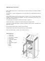
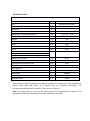
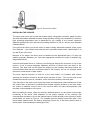
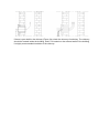
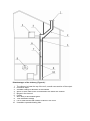
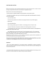
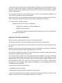
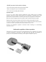
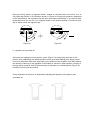
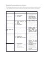
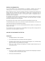
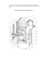
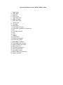
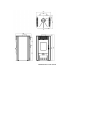
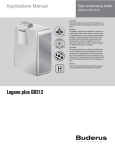
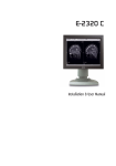
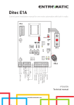
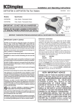
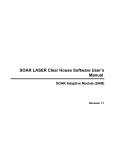
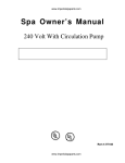
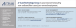
NIKA- HYDRO Fireplace stove on solid fuel Owners’s manual INSTALATION, ADJUSTMENT AND OPERATING INSTRUCTION EN 13240 Dear Customer, We appreciate your trust wested in us and decision to use "TIM SISTEM" product. You have invested in energy-efficient and high-quality product – NIKA HYDRO wood burning stove. Your purchase will provide you long-term clean and comfortable heating with minimal maintenance. Please read these instructions carefully and completely. The purpose of the manual is to inform you about the installation, operation and maintenance of your stove. Keep it handy and refer to it as needed. You will find in it information that will be useful now and in the years to come. Make sure that when installing the stowe all security standards have been respected and that all gas pipes, connections between tubes and pipes and walls are connected properly. Disregarding these standards and negligence during installation can result in damaging your property or put your health and life in danger ! Set your stove to a safe place, away from the frequent passages and doors, somewhere near chimney and chimney connection. We wish you many pleasant moments with NIKA HYDRO. TIM SISTEM d.o.o. CONTENTS WARNING BEFORE USE ............................................................................ Error! Bookmark not defined. DECRIPTION OF THE STOVE...................................................................... Error! Bookmark not defined. INSTALLING THE STOVE ............................................................................ Error! Bookmark not defined. IGNITION AND LIGHTING.......................................................................... Error! Bookmark not defined. HANDLING THE STOVE OPERATION ......................................................... Error! Bookmark not defined. I –authomatic ragulation of stove operation (regulation of primar air) .............Error! Bookmark not defined. II – regulation of secundary air ............................................................ Error! Bookmark not defined. INSTALLING THE STOVE INTO THE SYSTEM FOR WATER HEATING .......... Error! Bookmark not defined. Installaion on closed central heating system ....................................... Error! Bookmark not defined. Installaion on opened central heating system ..................................... Error! Bookmark not defined. CLEANING AND MAINTENANCE ............................................................... Error! Bookmark not defined. MALFUNCTION. RECOMENDATION FOR ITS ELIMINATION ..................... Error! Bookmark not defined. GENERAL RECOMMANDATION ................................................................ Error! Bookmark not defined. ADVICES FOR ENVIROMENT PROTECTION ............................................... Error! Bookmark not defined. Packaging.............................................................................................. Error! Bookmark not defined. Product ................................................................................................. Error! Bookmark not defined. WARRANTY ............................................................................................... Error! Bookmark not defined. WARNING BEFORE USE To keep your stove working properly, it is important to read this manual and strictly stick to the instructions for use and handling. For combustion use solid fuels such as wood and wood briquettes. It is forbidden putting explosive devices and materials combustion chamber or the limited thermal furnace. It is forbidden to keep flammable materials near the stove. For proper combustion, in normal operating mode, draft in the chimney should be 10-12PA. If the draft is greater than 15Pa, the valve should be installed in the chimney. Room where the stove is positioned must be vented regularly for the fresh air needed for combustion. Some parts of stove heat up during operation and it takes appropriate precaution when handling it. Do not allow children to handle and play near the stove. Only spare partes reccomended and allowed by the manufacturer should be installed on the stove . You must not make any changes on the stove. With first firing there might show a mild smoke, especially from the plate’s surface. It is a common appearance that occurs due to combustion deposits on the plate’s surface (corrosion protection, paint, dust, ....). The room where the stove should be vented during the first firing. It’s not reccomended connecting the stove to the common chimney because it can adversely affect the required draft. Device that uses gas as fuel must not be connected to same chimney. During firing, use protection gloves because the door handles get heated. National and local regulations for the installation of the furnace must be respected. In a case of diregarding instructions given in this manual, manufacturer does not take any kind of responsability for caused damage. DESCRIPTION OF THE STOVE NIKA HYDRO storey stove is manufactured and tested according to European standard EN 13240. On the figure 1 is shown the appearance of the stove with all it's components important for handling. NIKA HYDRO fireplace stove has a boiler (figure 1, position 11), 12.5 l volume made of boiler tin-plates, tickness prescribed by standards. This kind of manufacture prolongs life of the boiler. Water connections are 1. The upper plate of the fireplace is made of steal (figure 1, position 1) Firebox doors (figure 1, position 4) are made of cast iron with fireproof glass. Connection for smoke drain (figure 1, position 2) is made of cast iron and it’s installed on the plate with 2 screws. All the materials that the stove is made of can be recycled. Sealing elements are made of materials that doesn’t contain asbestos. Grid in the firebox (figure 1, position 10) is made of cast iron. Parts of the stove: 1. Upper plate 2. Smoke drain 3. Secondary air regulator 4. Firebox door 5. Firebox door handle 6. Glass 7. Ashtray 8. Authomatic regulator 9. Lever 10. Grid 11. Boiler TECHNICAL DATA Name NIKA HYDRO Use Solid fuel sorey stove Nominal power kW Efficiency % Fuel 20 84 Dimensions of the stove WxLxH mm 705 x 441 x 760 Dimensions of the firebox WxLxH mm 574 x 260 x 280 kg 153 Back mm 500 Lateral mm 500 Front Content of CO (reduced on 13% O2) Wood Emission of CO(reduced on 13% O2) mm % 800 Chimney connection mm Weight Minimum distance from flammable materials 0,091 Chimney connection position Consuption by nominal power Emission temperature Ø150 Central on upper plate kg/h 2,65 °C 241 Air regulation Primary Automatski (Rathgeber) Secundary Required amount of water in the boiler Required draft Manual l 12,5 Pa 12-15 Storey stove is made for heating of residential premises. An integral part of the installation is thermal drain valve that serves as a thermal fuse of a possible overheating. The recommended thermal fuse is Caleffi 1/2 544, shown in Figure 2. Note: The thermal fuse is not part of the product and it's not supplied with the product. The guarantee is valid only if the termar fuse gets installed into the boiler. Figure 2. Thermal fuse Caleffi INSTALLING THE COOKER The stove must not be set up near the wooden parts, refrigeration elements, plastic furniture and other flammable materials because during operation (during fuel combustion) it achieves high operating temperature that is distributed on the outside of the furnace. Minimum distance between the stove and the surrounding elements is 50 cm, and the from flamable materials 80 cm. If the ground on which you set the stove is made of easily flammable material (wood, warm floor, laminate ...) you need to set under the stove a protetion sheet metal - lateral width of 10 cm and 50 cm in the front. Because of it’s weight, the stove must be installed on the appropriate base. If it does not satisfie necessary standard, you must take appropriate measures to make it possible (eg, weight distribution). Connect the fireplace stove to a chimney and flue pipes through the connector on top of the furnace, so as to ensure adequate tightness and flow of smoke from the stove to the chimney. Flue pipe must not be drawn too deeply into the chimney that would reduce the cross sectional area and thus undermined draft in the chimney. Do not use reducers which reduce the cross section of pipe smoke. The stove requires insertion of fresh air in the room where it is installed, with surface openings for insertion of fresh air should not be less than 0.4 dm ². The unit for fresh air set outside the common room for ventilation, which must be insured by door and gride. Fans that work in the same room where the cooker is installed may make interference wit the the cooker. Also, all devices or ventilation that creates negative pressure in the room where the cooker is installed, must be set in the way that does not make decompression that prevents normal operation of the stove. Before installing the stove, check the chimney drafts because it is a key factor in the proper functioning of the stove. Draft depends on the proper opration of the chimney and meteorological conditions. One of the easiest ways to check the draft in the chimney is with a candle flame, as shown in Figure 3 . Put a candle near the chimney connection drain. If the flame bends towards drain, the draft is satisfying (Figure 3b). If the flame doesn’t bend or bends a little, that indicates poor draft(Figure 3a). If there is poor draft in the chimney (Figure 3a), check the chimney functioning. The chimney should be located inside the building, and if it’s located on the external walls of the building, it’s highly recommended insulation of the chimney. Disadvantages of the chimney (Figure 4): ` 1. 2. 3. 4. 5. 6. 7. 8. 9. 10. The chimney is lower the top of the roof, a small cross section of the output. Excessive slope A sudden change of direction of the channel Stove or some other evice is connected to the same flue channel Bulges in the channel Cracks Alien body or acumulated grime Tube inserted to deeply Fan or other device that creates a vacum in the room Unseald or opened cleaning hole IGNITION AND LIGHTING Before the first firing, wipe all painted surfaces with a clean and dry cloth, in order to avoid burning of impurities on the stove and creation of unpleasant smells. Start the fire in the stove by following order: • pull the primar air regulator handle counterclockwise to the maximum point • secundary air regulator leave open untill the flame gets stabile and afterwards fire intensity control wih regulator • open the firebox door • insert the firing material in the firebox (tiny chopped wood on dry wrinkled paper) • light the fire • close the firebox door, • after creating a basic glow in the firebox, insert larger pieces of wood or coal, close the firebox door and push the handle of the draft regulator to the stove If fuel briquettes are used as a fuel, you must wait until entire amount of a fuel lightens up and only then reduce draft on half • when adding fuel,open the firebox door for just few degrees,wait for 4-5 seconds and then slowly open them wide. Do not open the door suddenly, because when there is a high flame in the firebox, it can could easily reach in to room. Regulating the draft in the stove, you can regulate temperature, power and the combustion of fuel. Recommended fuels are briquettes and wood. You must not use gasoline and similar fuels, because by using liquid fuels you crate conditions for damaging the stove and to provoce an explosion. Attention! • Do not use organic wasteas fuel, food residue, plastic, combustible or explosive materials, which combustion disturbs the proper functioning of the cooker and may cause damage and environmental pollution. • Increased ambient temperature can cause poor air circulation (drafts) in the chimney, and in that case is recommended more frequent firing in smaller quantities. • Avoid using the stove when there are bad weather conditions for the stove operation and in the case of strong wind, because it reflects the required vacuum in the chimney. In these cases there may occure potential return of smoke in the room where the cooker is placed. Ignition is difficult then. We recommend firing every hour with the amount of fuel in the combustion chamber up to 15cm with cross stacking wood for better airflow. After each refilling, it’s reccomender to leave the stove running in full speed for 30 minutes,in order to destroy all volatile elements that may cause condesation in the cooker. For correct cooker operation it takes: - Regular cleaning of the cooker and chimney - Regular room ventilation for better combustion - Regular ash tray cleaning Accumulated slag and unburned material regularly remove from the grid with an adeguate cleaning kit HANDLING THE STOVE OPERATION Start a fire with a moderate flame in order to avoid thermal shocks. The following amounts of wood are inserted only after the previous volume burn. Do not allow that ashes and unburned accumulate on the grid and to ta pit that way. Clean the grid. Open the door slowly and carefully, allowing, that way, equalization of pressure in the firebox and in the room, otherwise it might cause the smoke in the room. The cooker is designed and made for use with firebox door constantly closed, except during refueling. Do not open the door with no need. The wood must be a maximum of 20% moisture content for maximum fire effect. Otherwise the tar gets separated which with water steam may crate creosite. If that happens in some bigger quantitiy, it may lead to a chimney fire. You will most easily recognize chimney fire by: the characteristic sound that comes out of the chimney like loud roaring, visible flames coming out of the chimney, high ambient temperatures of surrounding walls and the characteristic smell of burning. If there comes to the fire do the following: • Immediately call the fire squad • muffle oxygen supply to the chimney and turn off the cooker • Do not insert anything into the chimney and make sure that the fire does not spread to the wooden construction or other combustible materials in its nearby. • DO NOT pour water into the cooker or chimney • A fire in the chimney can be extinct only with dry powder • Water can extinguish only a surrounding material • Do not cool the surrounding walls with water Important notice: If the fire, for some reason becomes dangerously strong, please take the following measures: close the air supply, which provide air for combustion. If necessary, throw in the firebox sand or fireproof blanket. It would be good having fire extinguisher for that purpose. Before the second charging, clean the rost grid in order to provide the fresh air supply. Regularly clean the ash tray making sure that there is always enough place for ashes. The stove is designed to operate in periodic mode. To maintain the required nominal power, combustion chamber is periodically filled with prestabled amount of fuel. Furnace is not designed to operate in continuous mode of heating or in accumulating temperature mode. Authomatic regulation of stove operation Combustion rate, and thus the amount of heat generated by stove, depends on the amount of primary combustion air delivered to the space below the roast grid. The regulation of primary air is accomplished automatically by draft regulator Rathgeber (Figure 5). During the firing, primar air regulator button, located on the back side of the stove, turn to fully open flap position, in the direction shown in Figure 6a. During the operation, depending on the temperature, the regulation flap will open and close automatically. If you want a lower temperature than the set one, turn regulator button to the desired position of minimum open flap 6, which closes the regulator flap. Figure 6a Figure 6b II - regulation of secondary air Secondary air regulator put into position „open“ (Figure 7a) during firing and keep in this position until establishing the stable operation of the stove after loading some larger pieces of wood or briquettes. After that, depending on the position of the regulator it will also depend the intensity of burning. If the regulator of secondary air remains in open position, intensity of burning will be maximal, while if the secondary air regulator is in closed position (Figure 7b) intensity of burning will be minimal. Power regulation of the stove is obtained by adjusting the regulator of the primary and secondary air. INSTALLING THE COOKER INTO THE SISTEM FOR WATER HEATING - For water supply and drainage in condominial (central) heating system are provided connections to the boiler 1 ". - The stove can be installed on an indoor or outdoor central heating system. Installation on closed central heating system One of the possible installation processes is shown in Figure 8. -The safety valve must be placed close to the boiler and must be set to a maximum pressure of 3 bar (boiler is tested to 4 bar). The connecting line of the safety valve must be as short as possible and must not have the possibility of closing. In this connecting line also there must not be any single valve or any other fitting. -Closed expansion vessel is placed close to the boiler and has a short security line. The volume of the expansion vessel is calculated by the folloving formula: V = 0,07xVwater, (l), where Vwater is volume of the water in entire system. -The installation of the safety fuse of the boiler it's necessary. We highly recommend a Caleffi 544 thermal fuse. - The instalation of vent valve (authomatic preferably) - Before starting the stove, it’s necessary to vent the system Figure 8. closed central heating system Installation on opened central heating system One of the possible installation processes is shown in Figure 9. With this system, on the initial line are being set safety distribution line of the expansion vessel and boiler's valve, and on the initial line of the system are being set boiler's valve, a pump and a valv. Directly below the open expansion vessel is set short connection between safety distribution line and safety rebound line, which prevents water freezing on winter in an expansion vessel. On safety distribution line and safty rebound line, must not be any kind of fitting. Expansion vessel must have an overflow pipe as shown on the chart in Figure 9. The volume of the expansion vessel is calculated by the folloving formula: V = 0,07xVwater, (l), where Vwater is volume of the water in entire system. Open expansion vessel is placed vertically above the highest heating body. Under the open heating system is possible having gravitational heating system. Note: Installation of the heating system and starting up of the entire system should be entrusted exclusively to professional service in charge that guarantees the correct operation of the entire heating system. In case of bad design of the system and possible shortcomings while installing it by the entity that did the work, complete material responsibility takes the person to whom was entrusted installation of heating systems, and not a producer, rappresentative or seller of the boiler. Important notice • Installation of the stove should be done by qualified person according to an appropriate project. Construction of the stove allows you to connect it either to indoor or outdoor heating system. All connections must be well sealed and fastened. Prior to starting it up, the complete installation must be tested with water at a pressure of 3 bar. • When installing the safety valve, please pay attention to the direct connection with water pipes and sewer, and that valves (faucets) always stay open. • If using a reinforced hose to connect to the drainage, it must be placed away from the back side of the cooker. With first ignition is necessary to examine the the proper functioning of the valve by doing the following: overheating it up to 100 ° C on short-term basis, examining the proper function of draft regulator and installing hot water distribution connection up to radiators and directly to radiators. Figure 9. Open central heating system CLEANING AND MAINTENANCE Regular and proper cleaning allows proper operation and long life of the stove. All cleaning the interior or exterior surfaces are always performed in a cold oven. Cleaning exterior surfaces - is done with a soft cloth that will not damage the surface of the stove. Cleaners of chemical origin can damage the surface of the fire place and cannot be used. Painted surfaces must not be cleaned with abrasive products. Cleaning inter surfaces –when cleaning use protective gloves. Clean the bottom of the ovenfrom accumulated ash and pick up small unburned pieces of the grid, clean the ashtray and ash accumulated in the interior of the fireplace. Cleaning glass surfaces - glass on the firebox may get dirthy during the operation.. For cleaning use a mild detergent. Do not use abrasive cleaners because they can damage the surface of the glass. Clean the glass only when cool. Cleaning and maintenance of the chimney - chimney cleaning and control is recommended at least once a year and after a long downtime. Regular maintenance and control of the chimney will prevent the occurrence of fire and poor operation of the stove. Malfunction. Recommendations for its elimination The following table shows the most common defects and recommendations for their removal. Table: Showing the most common malfunctions, possible causes and ways of eliminating it. Malfunction Possible cause Oven heats poorly Difficulties in lighting fire Smoke room reenters into a Glass on a firebox door are getting sooty in a while Insufficiant heat of the radiator, less then 50 °C improper handling, Closed supply, Wet wood, regulator Closed supply, Insufficient draft, of Read carefully and follow the instructions. Inthe case that despite all instructionshave been respected, malfunctions are still not removed, call the customer service Open the regulator of air supplyand provide a supply of a primary air Use a dry wood Open the regulator of air supplyand provide a supply of a primary air Read carefully the instructions and apply advices how to provide a draft Clean the grid Check a connection with a chimney Read carefully the instructions and apply advices how to provide secundary air Read carefully and follow the instructions. Turn off from the system superfuous radiators if their power exeeds the power which stove ggives to the water Relase air from the system air Lack of oxygene Poor uptake Howe to remove it regulator of air Remainings of ashes on a grid Wet wood Too much fuel Insufficient draft Closed intake of secundary air Improper handling Poor uptake Overdimension heating system Air in sthe system Insufficient pump power Ventilate a room in order to provide a supply of fresh air Use a dry wood Check a suggested quantity of a fuel provided in a user’s manual GENERAL RECOMMANDATION If you have fullfield all the recommendations for installation, operation and control of cleaning, giveen in this manual, the stove is now tested, safe device for household use. Before installing the stove, remove the package. Be aware of potential injuries because the wooden slats are connected with nails. Dispose a plastic bag in accordance with the regulations. Old stove you do not want to use anymore, dispose to designated areas in accordance with the regulations. All complaints, perceived failure or malfunctioning stoves, should be reported to the factory or authorized service center by telephone or in written, only with fiscal receipt. All contact information provided at the end of this guide. Any malfunction of the cooker, must be removed by the manufacturer’s service only. If unauthorized persons carry out any servicing or repairs and alterations to the stove, the owner loses the right to the manufacturer's warranty. Supply of spare parts has to be done viamanufacturer’sservice, based on the position and image of this manual. The manufacturer does not assume any responsibility if the buyer fails to comply with the instructions for use and installation of the stove. ADVICES FOR ENVIRONMENT PROTECTION PACKAGING Packaging material is 100% recyclable. For a waste disposal act in accordance with local regulations. Packaging material (plastic bags, polystyrene parts-polystyrene, etc.). should be kept away from children, as a potential source of danger. Take care of safe removing and disposing of wooden boards because they are connected with nails. PRODUCT The device is made of materials that can be recycled. When disposing the waste,act in accordance with enviromental laws in effect. Use only the recommended fuel. It is forbiden burning an inorganic and organic materials (plastics, plywood,textile, oiled wood, etc..), because the combustion releases carcinogenic materials and other toxics. FIREPLACE SOLID FUEL STOVE NIKA-HYDRO List of all Positions on the "NIKA HYDRO" stove 1. Upper plate 2. Down plate 3. Mid plate 4. Stove cover 5. Upper back side 6. Boiler structure 7. Down back side 8. Lateral side 9. Top plate 10. Grid carrier 11. Grid cleaner structure 12. Authomatic regulation of a primar air 13. Pin 14. The base structure 15. Grid 16. Lever 17. Ashtray 18. Firebox door 19. Firebox door handle 20. Firebox door glass 21. Secondary air handle 22. Decorating cover stucture 23. Sealing firebox door bride 24. Back vermiculit 25. Inspection opening lid 26. Front side structure 27. Secundary air box 28. Bottom side boiler structure 29. Upper vermiculit Dimensions of the stove WARRANTY The warranty is valid from the date of purchase, as evidenced by duly completed guarantee certificate, so called Protocol. Protocol contains the following details: buyers address, seal and signature of the seller. Detail protocol must be released by the offitial seller of TIM SISTE product. This warranty will be accepted only if: Product has been used according to this manual Product is not fisicaly damaged Warranty protocol has been certified by the seller of TIM SISTE product or it’s service in charge Name NIKA - HYDRO Serial number Date of purchase Seal and signature of the seller or service in charge NOTES: __________________________________________________________________________ __________________________________________________________________________ __________________________________________________________________________ __________________________________________________________________________ __________________________________________________________________________ __________________________________________________________________________ __________________________________________________________________________ __________________________________________________________________________ __________________________________________________________________________ __________________________________________________________________________ __________________________________________________________________________ __________________________________________________________________________ __________________________________________________________________________ __________________________________________________________________________ __________________________________________________________________________ __________________________________________________________________________ __________________________________________________________________________ __________________________________________________________________________ __________________________________________________________________________ __________________________________________________________________________ __________________________________________________________________________ __________________________________________________________________________ __________________________________________________________________________ __________________________________________________________________________ __________________________________________________________________________ __________________________________________________________________________ __________________________________________________________________________ __________________________________________________________________________ __________________________________________________________________________ __________________________________________________________________________ __________________________________________________________________________ __________________________________________________________________________ __________________________________________________________________________ __________________________________________________________________________ __________________________________________________________________________ __________________________________________________________________________ __________________________________________________________________________ __________________________________________________________________________ __________________________________________________________________________ __________________________________________________________________________ __________________________________________________________________________ __________________________________________________________________________ __________________________________________________________________________ __________________________________________________________________________ __________________________________________________________________________ __________________________________________________________________________ TIM SISTEM d.o.o. Prva industrijska 9, 22330 Nova Pazova, Serbia tel: +381 22 328 076 e-mail : [email protected] www.timsistem.rs