1
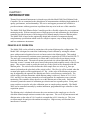
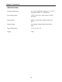
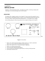
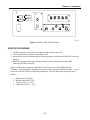
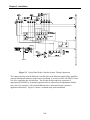
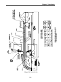
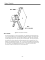
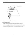
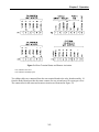
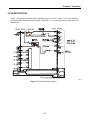
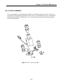
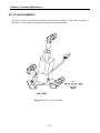
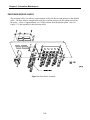
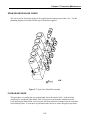
Model 200L
Instruction Manual
Dual Dilution Probe Controller
Part Number 14638
20Dec2007
© 2007 Thermo Fisher Scientific Inc. All rights reserved.
Specifications, terms and pricing are subject to change. Not all products are available in all countries. Please
consult your local sales representative for details.
Thermo Fisher Scientific
Air Quality Instruments
27 Forge Parkway
Franklin, MA 02038
1-508-520-0430
www.thermo.com/aqi
WEEE Compliance
This product is required to comply with the European Union’s Waste
Electrical & Electronic Equipment (WEEE) Directive 2002/96/EC. It is
marked with the following symbol:
Thermo Fisher Scientific has contracted with one or more
recycling/disposal companies in each EU Member State, and this product
should be disposed of or recycled through them. Further information on
Thermo Fisher Scientific’s compliance with these Directives, the recyclers
in your country, and information on Thermo Fisher Scientific products
which may assist the detection of substances subject to the RoHS Directive
are available at: www.thermo.com/WEEERoHS.
Thermo Fisher Scientific
WEEE Compliance
TABLE OF CONTENTS
CHAPTER 1 INTRODUCTION ..........................................................................1-1
Principle of Operation...................................................................................................... 1-1
Specification ...........................................................................................................1-2
CHAPTER 2 INSTALLATION............................................................................... 2-1
Unpacking ........................................................................................................................ 2-1
Installation Procedure ..................................................................................................... 2-2
System Plumbing Connections ........................................................................................ 2-2
Startup Procedure............................................................................................................. 2-3
CHAPTER 3 OPERATION ................................................................................3-1
Electronics........................................................................................................................ 3-1
Relay Board.......................................................................................................... 3-2
Switch Board........................................................................................................ 3-3
Rear Terminal Board............................................................................................ 3-4
Gauges ....................................................................................................................3-6
Flow Description.............................................................................................................. 3-7
Subassemblies ................................................................................................................. 3-8
CHAPTER 4 CALIBRATION ...................................................................................... 4-1
Equipment Required ........................................................................................................ 4-1
NOx Concentration Standard .....................................................................................................4-1
Dilution Probe ................................................................................................................. 4-1
Dilution Probe Technique ............................................................................................... 4-2
Dual Dilution Configuration ............................................................................................ 4-3
Dilution Calculations...................................................................................................4-4
CHAPTER 5 PREVENTIVE MAINTENANCE....................................................5-1
Safety Precautions............................................................................................................ 5-1
Replacement Parts List..................................................................................................... 5-2
Relay Board Replacement................................................................................................ 5-3
Switch Board Replacement.............................................................................................. 5-4
No. 8 Valve Assembly ..................................................................................................... 5-5
iii
No. 12 Valve Assembly ................................................................................................... 5-6
No. 13 Valve Assembly ................................................................................................... 5-7
Precision Orifice Check ................................................................................................... 5-8
Span Solenoid Valve Check............................................................................................. 5-9
Flow Leak Check ............................................................................................................. 5-9
Spare Parts ..................................................................................................................... 5-10
Service Locations........................................................................................................... 5-11
CHAPTER 6 TROUBLESHOOTING .................................................................6-1
Troubleshooting Guide .................................................................................................... 6-1
APPENDIX A WARRANTY............................................................................... A-1
APPENDIX B SCHEMATICS ..................................................................... B-1
LV200 AC Wiring Schematic..........................................................................................B-1
Main Control & Relay Board...........................................................................................B-2
200L Switch Board (Dual and Single) .............................................................................B-3
Terminal Board ................................................................................................................B-4
iv
LIST OF ILLUSTRATIONS
Figure
Page
2-1. Front Panel................................................................................................................ 2-1
2-2. Model 200L Dual Probe Controller Rear Panel ....................................................... 2-3
2-3. Typical Dual Probe Controller System Line Connections........................................ 2-4
2-4. Dilution Probe .....................................................................................................2-5
3-1. Relay Board Assembly ............................................................................................. 3-2
3-2. Switch Board Assembly ........................................................................................... 3-3
3-3. Rear Terminal Board ................................................................................................ 3-4
3-4. Rear Terminal Status and Remote Activation .......................................................... 3-5
3-5. Gauge Locations ....................................................................................................... 3-6
3-6. Dual Probe Controller Plumbing Diagram ............................................................... 3-7
3-7. Case Bottom Assembly Layout ................................................................................ 3-8
4-1. Sonic Orifice Assembly............................................................................................ 4-3
4-2. Typical Dual Probe Controller Line Connections .................................................... 4-4
5-1. Relay Board Assembly ............................................................................................. 5-3
5-2. Switch Board Assembly ........................................................................................... 5-4
5-3. No. 8 Valve Assembly.............................................................................................. 5-5
5-4. No. 12 Valve Assembly............................................................................................ 5-6
5-5. No. 13 Valve Assembly............................................................................................ 5-7
5-6. Rear Panel Assembly................................................................................................ 5-8
5-7. Span Valve Manifold Assembly............................................................................... 5-9
v
LIST OF TABLES
Table
Page
4-1. Sonic Orifice Sizes ................................................................................................... 4-5
5-1. Replacement Parts .................................................................................................... 5-2
5-2. Recommended Spare Parts ..................................................................................... 5-10
vii
CHAPTER 1
INTRODUCTION
Thermo Environmental Instruments is pleased to provide this Model 200L Dual Dilution Probe
Controller. We are committed to the manufacture of instrumentation exhibiting high standards of
quality, performance, and workmanship. TEI service and support personnel are available to
provide assistance with any questions or problems that may arise in the use of this controller.
The Model 200L Dual Dilution Probe Controller provides a flexible solution for your continuous
monitoring needs. With an external source of high-pressure air and calibration gas, the dilution
controller provides the means of delivering precisely diluted samples from two dilution probes.
The Model 200L is based on the engineering design and selection of components having
complementary specifications which result in a simple to operate, easy to adapt, high accuracy,
and low maintenance instrument.
PRINCIPLE OF OPERATION
The Model 200L can be utilized in conjunction with various dilution probe configurations. The
Model 200L is designed to control the conditioning of stack effluents by mixing the exhaust
gases with pressurized regulated zero air at a known ratio in the dilution probe. This method
meets the requirements for emission source monitoring as required in 40 CFR 60 and 40 CFR 75.
The stack gas is extracted continuously via filters and a critical orifice by an eductor section
inside the dilution probe. The main air stream (pressurized air) with an adjustable flow of Q1
litres/min. creates a vacuum in the space between the primary and secondary nozzle of the ejector
pump. This vacuum is used to extract the stack gas via the critical orifice mounted inside the
dilution probe. The critical orifice defines the stack sample flow at a value of Q2 litres per
minute (indicated on the glass body of the critical orifice). The flow Q2 will be reached when the
vacuum in the probe exceeds approximately 10” Hg. As the value of the dilution air pressure
may be adjusted by the operator, the dilution ratio can be varied between certain limits. The
critical orifice selection determines which dilution setting is achieved. Ratios of 50:1, 100:1,
150:1 and 200:1 are the most commonly used configurations for combustion source emission
monitoring. The controller allows the user to set the dilution ratio of the probe. Solid state
electronics permit the control of calibration gas selection and two separate probes. Front panel
rotary switches are used to select the calibration gases or sample probes manually. The Model
200L can be controlled externally by another instrument, programmable logic controller or data
acquisition system.
The dilution ratio is calculated to decrease the water moisture in the sample gas to a level at
which the diluted sample moisture remains in the vapor state. The use of dry instrument air and
dilution ratios on the order of 100:1 results in a sample that is 99% clean dry air. This is an
excellent sample for analysis with ambient air analyzers. High accuracy and freedom from
interference is assured.
1-1
Chapter 1 Introduction
SPECIFICATIONS
Operating Temperature
60 to 100 oF in NEMA 1 Enclosure -25 to 125 oF
in optional NEMA 4 or 12 Enclosures
Power Requirements
115/230 Volts ±10%, single -phase, 50/60 Hz,
200 Watts
Remote Inputs
Ability to Control Zero, Sample, and 5 Span
Ports.
Output Contacts
Zero, Sample, Sample Probe Selected and 5
spans.
Physical Dimensions
17” W x 8 ¾” H x 23"
Weight
38 lbs.
1-2
CHAPTER 2
INSTALLATION
Installation of the Model 200L includes: unpacking the controller, connecting a sample probe,
connecting zero air and calibration gas lines to the controller.
UNPACKING
The Model 200L is shipped complete in one container. If, upon receipt of the controller, there is
obvious damage to the shipping container, notify the carrier immediately and hold for inspection.
The carrier, and not Thermo Environmental Instruments Inc., is responsible for any damage
incurred during shipment. Follow the procedure below to unpack and inspect the controller.
Figure 2-1: Front Panel
1. Remove the controller from the shipping container and set it on a table or bench that
allows easy access to both the front and rear of the instrument.
2. Remove the controller cover to expose the internal components.
3. Remove any internal packing material.
4. Check for possible damage during shipment
5. Check all connectors and printed circuit boards to see if they are firmly attached.
6. Re-install the controller cover.
2-1
Chapter 2 Installation
INSTALLATION PROCEDURE
Before making any connections to the rear of the control unit, refer to system documentation, if
supplied, for any details that may not be included in this manual. Check the Purchase Order
packing slip to ensure the unit was ordered in the correct configuration. If any of the information
is incorrect, contact your local Sales Representative or call a Sales Representative at Thermo
Environmental Instruments.
Before powering up the Model 200L Dual Dilution Probe Controller, make sure the transformer
configuration is correct for the power available.
SYSTEM PLUMBING CONNECTIONS
Connecting the various lines to the rear panel of the Model 200L is illustrated in Figure 2-3. If
the unit was purchased with a system, please refer to the appropriate documentation for proper
connections. All tubing connected to the controller should be made of Teflon. With proper
configuration complete and checked, the startup procedure can be performed.
2-2
Chapter 2 Installation
62P734
Figure 2-2: Model 200L Dual Rear Panel
STARTUP PROCEDURE
1. Connect the power cord to the rear of the unit and turn the power ON.
2. Check to make sure the power switch light is ON.
3. Rotate each selector switch through its various positions to check that all the LED’s turn ON
properly.
4. While moving the switch, listen for the solenoid valves clicking into position while
observing the LED’s turn ON.
Figure 2-3 illustrates a common connection to a rack system for a Dual Dilution Probe
Controller. Eight plumbing connections are critical to the operation of the Model 200L. A set of
four lines from each of the two dilution probesprobes. The four lines from each probe are as
follows:
1.
2.
3.
4.
Dilution Air (DA, DA2)
Diluted Sample (DS, DS2)
Vacuum Line (VL1, VL2)
Calibration Line (CL1, CL2)
2-3
Chapter 2 Installation
Figure 2-3: Typical Dual Probe Controller System Tubing Connections
The connection lines from the Dilution Controller Unit to the Dilution Sample Probe should be
properly labeled and connected to the correct port fitting. A pressure of 80 to 100 PSIG of clean
zero air is supplied to the Air Inlet Port. The Air Inlet is then reduced to a pressure of
approximately 40 PSIG by an internal regulator which is adjusted for the appropriate dilution
ratio (100:1 for example). (The selected dilution ratio is determined by the customer’s
application data sheet.). Figure 2-4 shows a common stack probe installation.
2-4
Chapter 2 Installation
Figure 2-4: Dilution Probe
2-5
CHAPTER 3
OPERATION
In order to fully understand the operation of the Model 200L, a general knowledge of the
electronics, flow, and subassemblies is recommended. A better understanding of the components
themselves will allow the user to more efficiently change parts or subassemblies.
ELECTRONICS
The Relay and Switch boards are the primary active electronic components mounted in the
Controller. Positive 24 Volts DC from the Relay Board activates the solenoid valves. The
position of the selector switch determines which solenoid valve or valves are activated in order to
allow air or gas flow through the Model 200L Dilution Controller. The rear terminal board
delivers dry contact status outputs which can be connected to a data acquisition unit. The
controller can be activated remotely by a data logger or similar device.
3-1
Chapter 3 Operation
Figure 3-1. Relay Board Assembly
RELAY BOARD
The relay board supplies +24 Volts to the solenoid valves, depending upon the position of the
switch. The Relay Board is part of the Regulator-Relay Board Assembly. Three ribbon cables
are attached to the relay board. One of the cable assemblies is connected to the switch board
assembly and the other two are connected to the rear terminal board. The relay board controls
the position of the valves and provides solid state contacts to the rear connector board. See
appendix B for Relay Board schematic. The +24 Volts DC goes through the relay board and is
delivered to the Switch Board Assembly. The switch from the Switch Board Assembly delivers
the +24 Volts DC to the appropriate solid state relay. A ¼ Amp fuse is used for safety
prevention of surge current while the unit is in the sample mode.
3-2
Chapter 3 Operation
Figure 3-2. Switch Board Assembly
SWITCH BOARD
A rotary switch selects the Mechanical Relays on the Relay Board Assembly. The Rotary switch
uses indented stops to select from zero, sample, and 5 span valves. A total of 13 LED’s are
seated on the front panel. The three LED’s aligned horizontally at the bottom are not used for the
dual probe configuration. The LED’s will only be used in the dual probe controller unit.
3-3
Chapter 3 Operation
Figure 3-3. Rear Terminal Board
REAR TERMINAL BOARD
The Rear Terminal Board provides status contacts for zero, sample, and 5 span valves. A
constant +24 Volts DC is present at the Rear Terminal Board for remote activation by a data
acquisition system or relay contact configuration. In order to activate for zero, sample or the 5
span valves, +24 Volts DC is delivered to the appropriate terminal connection from a dry contact
closed state. All valves are in the de-energized state, meaning that both lines to the solenoid
valve are at a zero volt potential.
3-4
Chapter 3 Operation
Figure 3-4. Rear Terminal Status and Remote Activation
* NU, indicates Not Used.
* NO, indicates Normally Open.
Two ribbon cables are connected from the rear terminal board to the relay board assembly. J9
from the Relay Board provides the status contacts for zero air and one to five span gas valves.
The connections for the status and remote activation are illustrated in Figure 3-4
3-5
Chapter 3 Operation
The dual probe controller has additional valves to control the indication of the probe vacuum and
dilution air pressure gauges and to select the source of dilute sample gas. A voltage of 24 Volts
switches the valves from common to either normally OPEN or normally CLOSED. With no
potential across the valve, then the path of the valve would go from common to normally OPEN
(NO). With a potential of 24 Volts across the two leads of the valve, then the flow through of the
valve would be from common to normally CLOSED (NC). Refer to flow diagram Figure 3-6. In
a de-energized state, the indications and sample selected will be from dilution probe one.
Figure 3-5. Gauge Locations
GAUGES
Three gauges are affixed to the front panel of the Model 200L, probe vacuum, dilution air
pressure, and zero air. Figure 3-5 illustrates the location for the gauges. The dilution air pressure
should be set to approximately 40 PSIG to obtain a sample dilution rate of 100:1 (with a 50
ml/min orifice). If this pressure is below 30 PSIG, then a leak check should be performed. Refer
to the Troubleshooting section for leak checking the Model 200L. The vacuum gauge indication
corresponds to the vacuum applied to the orifice in the dilution probe.
3-6
Chapter 3 Operation
FLOW DESCRIPTION
Figure 3-6 illustrates the Model 200L plumbing diagram in detail. Figure 3-6 is a flow diagram
for a dual probe configuration with sample switching, i.e., two sample points and only one set of
instruments.
62P817
Figure 3-6. Dual Plumbing Diagram
3-7
Chapter 3 Operation
SUBASSEMBLIES
The following subassemblies are available from Thermo Environmental Spare Parts
Department. With subassemblies, it is easier to replace components or troubleshoot in an
efficient manner.
Figure 3-7. Case Bottom Assembly Layout
3-8
CHAPTER 4
CALIBRATION PERFORMANCE
This chapter describes the procedure for performing the multipoint calibration using the TEI
Model 42C as an example. The information described here should be sufficient to perform a
calibration check.
EQUIPMENT REQUIRED
NOx Concentration Standard
A Model 42C instrument to be used as reference analyzer. A cylinder of NO in N2 containing an
appropriate concentration of NO for the selected operating range of the analyzer under calibration
is necessary. The assay of the cylinder should be traceable either to a National Institute of
Standards and Technology (NIST) Air Standard Reference Material (SRM) or an NIST/EPA
approved gas manufacturer’s Certified Reference Material (CRM). A recommended protocol for
certifying NOx gas cylinders against a NOx, SRM or CRM is given in the USEPA. The NOx gas
cylinder should be recertified on a regular basis determined by the local quality control program.
DILUTION PROBE
Each dilution probe requires four lines to be connected to the probe controller. The lines are
listed as the Dilution Air, Calibration Line, Diluted Sample, and Vacuum Line. The Dilution Air
is the high-pressure air being supplied to the probe. The probe utilizes this pressurized air for
extracting and diluting the sample, calibration zero, or gas from the sonic orifice. The
Calibration Line is used to deliver either Zero Air or Span 1 to 5 gases. The dilution controller
directs the flow of the Zero Air or the Span Gas through the Calibration Line to the probe.
4-1
CHAPTER 4 CALIBRATION PERFORMANCE
DILUTION PROBE TECHNIQUE
Dilution probe technology may be generically defined as a sampling technique whereby a small
continuous sample is filtered and diluted at stack temperature prior to transport to a set of
analyzers. A preferred way to do this is with an in-stack venturi, in which preheated instrument
air serves the triple function of extracting the sample, dilution, and transporting it under pressure
to the remote analyzers. Figure 4-2 shows a typical system configuration.
Advantages of the technique, as contrasted to more conventional extractive systems, include:
1. Long filter life due to a very low sampling rate.
2. Elimination of heated probe and sample lines by lowering the dew point
below the coldest expected ambient temperature.
3. Elimination of all valving and electric utilities at the probe location.
4. Fail-safe sampling whereby analyzers are intrinsically protected from any
condensates or other matter from the source which could harm the sample
system or instrument.
5. All parts of the systems can be checked using calibration gases.
6. Conventional ambient-level analyzers (which may already be in use at the
site) are used, reducing training time for operators and utilizing existing
spare part supplies
4-2
CHAPTER 4 CALIBRATION PERFORMANCE
Figure 4-1. Sonic Orifice Assembly
DUAL DILUTION CONFIGURATION
Before any calibrations or testing is to be done to the Dilution Controller and the Sonic Orifice
Probe, the line connections from the Model 200L to the Sonic Orifice Probe should be properly
connected and verified. Refer to figure 4-2 for a typical dual probe controller connection.
4-3
CHAPTER 4 CALIBRATION PERFORMANCE
Figure 4-2. Typical Dual Probe Controller Line Connections
DILUTION CALCULATIONS
Calculations are performed in conjunction with a gas analyzer or rack of no more than five
analyzers. It is very important to be sure the information pertaining to the critical orifice used in
the dilution probe is accurate. If the orifice in the dilution probe is in question, then the probe
should be inspected for the proper sonic orifice. Refer to Table 4-1 for specific data on each
critical orifice.
4-4
CHAPTER 4 CALIBRATION PERFORMANCE
Table 4-1
Critical Orifice Sizes
20 Mil
50 Mil
100 Mil
200 Mil
P/N
P/N
P/N
P/N
200:1
100:1
50:1
20:1
If the appropriate critical orifice is determined, then the Model 200L can be adjusted.
Connect the analyzer to the Model 200L and allow the gas to flow through the dilution probe by
setting the Dilution Controller for the appropriate Span Gas. If the Concentration of the test
bottle is connected to Span 1 port, then turn the selector switch to Span 1 position. If a dilution
ratio of 100:1 has been established, then the concentration of the expected value can be
determined. Take the concentration value of the bottle and divide it by the ratio. For example, if
the value of the bottle for NOx is 500 PPM, then the reading on the instrument should be within
4% of 5 PPM. The concentration should be between 4.80 to 5.20 PPM. If the result of the
reading is not within 4%, then either the instrument being used is not calibrated properly or the
Dilution Controller needs to be adjusted for the appropriate value.
The dilution air is adjusted to mix the right amount of air with the gas in order to achieve the
correct dilution ratio. Adjusting the dilution air regulator clock-wise will introduce more air to
the probe, thus increasing the dilution ratio and reducing the instrument reading. Adjusting the
dilution air regulator counter-clock-wise will reduce the amount of air introduced to the probe,
thus decreasing the dilution ratio and increasing the instrument reading. Before adjusting the
dilution air regulator each time, wait for the flow of the air and gas to settle to a stable reading.
This can take several minutes if long sample lines are in use. The dilution ratio may swing in
either direction from the previous adjustments before actually stabilizing. Care should be taken
when adjusting the dilution air regulator. It is better to adjust the dilution air regulator with onequarter turns for adjustments, especially if the readings are close (within the 4%) of the expected
value of the dilution ratio. Once the right amount of dilution air to the probe has been achieved,
then the dilution air regulator should be left alone. Tighten the locking nut of the dilution air
regulator to keep the adjustment from changing. The controller should not have to be readjusted
unless maintenance is performed on the instrument or sample system.
4-5
CHAPTER 5
PREVENTIVE MAINTENANCE
This chapter describes the periodic maintenance procedures that should be performed on the
Model 200L to ensure proper, uninterrupted operation. Components have a limited life
expectancy, so periodic check or replacement of certain components or devices is necessary.
Precision Orifices and Gauges are a few components that should be properly checked for
continuous operations. This chapter also explains how to replace the Model 200L subassemblies.
It is recommended for the individual to be familiar with the subassemblies before attempting to
disassemble or repair the controller unit.
SAFETY PRECAUTIONS
Some internal components may be damaged by the discharge of static electricity. To avoid
damaging internal components, follow these precautions when performing any service procedure:
CAUTION:
Wear an antistatic wrist strap that is properly connected to earth ground
(note that when the analyzer is unplugged, the chassis is not at earth
ground).
If an antistatic wrist strap is not available, be sure to touch a grounded
metal object before touching any internal components.
Carefully observe the instructions in each procedure.
Remove the power cord from the unit when any of the assemblies are to
be replaced.
5-1
Chapter 5 Preventive Maintenance
REPLACEMENT PARTS LIST
Table 5-1 lists the part numbers of the major subassemblies in the Model 200L. Refer to
Figure 3-7 to identify their locations.
Table 5-1. Replacement Parts
Part number
Description
10546
Span Solenoid Valve
5
7368
Solenoid Valve 3-Way(No. 8,12,13)
1
10539
Precision Orifice
1
6984
Dilution Air Regulator
1
4546
Vacuum Gauge 30 in of HG
1
8105
Pressure Gauge 30 PSIG
1
4495
Flow Meter 2.5 LPM
2
5-2
Quantity
Chapter 5 Preventive Maintenance
RELAY BOARD REPLACEMENT
Equipment required:
New Relay Board Assy. (Part No. 14672)
Nut Driver or Adjustable Wrench
Flat Tip Screwdriver
Slide the unit from the rack cabinet, so the cover can be taken off. Remove the four screws that
hold the cover above the unit. The Relay Board and Switch Board assemblies should now be
accessible. Remove the unit and locate the Relay Board Assembly. Remove the two screws
holding down the Relay Board bracket. Remove any cables, connectors and lines that will
prevent the bracket from moving. Remove the fitting lines to the regulator. Once the assembly
is removed from the case, then the five screws can be removed from the relay board. Replace the
relay board with the new board and secure the board with the five screws that held the old relay
board. Install the assembly in the reverse order in which it was removed. Connect the
appropriate connectors to the numbered locations on the relay board. Apply power to the unit
and make sure the Relay Board is working properly by switching all the selection points.
Figure 5-1. Relay Board Assembly
5-3
Chapter 5 Preventive Maintenance
SWITCH BOARD REPLACEMENT
Equipment required:
New Switch Board Assy. (Part No.14669)
Nut Driver or Adjustable Wrench
Flat Tip Screwdriver
Slide the unit from the rack cabinet so the cover can be taken off and the Switch Board
Assemblies are accessible. Remove the four screws that hold the cover above the unit. Remove
the unit and locate the Switch Board Assembly. Remove the selector knob from the front of the
unit which is secured with two allen set screws. With an adjustable wrench, remove the nut from
the switch. Remove the screw from inside the controller unit that holds the bottom of the Switch
Board Assembly. Remove any connector or wiring to the switch board and then remove the
assembly from the case. Replace the assembly in the reverse order in which the assembly was
removed. Reconnect any cables and wiring to the switch board. Apply power to the unit and
make sure the Switch Board is work properly by switching all the selection points.
Figure 5-2. Switch Board Assembly
5-4
Chapter 5 Preventive Maintenance
NO. 8 VALVE ASSEMBLY
The valve assembly is used in the dual controller to switch between the two probes. The valves
are numbered to distinguish the difference of the valves. Each numbered valve provides different
functions in the dilution controller unit. No. 8 valve allows the stream of the measured sample
flow to the instruments.
Figure 5-3. No. 8 Valve Assembly
5-5
Chapter 5 Preventive Maintenance
NO. 12 VALVE ASSEMBLY
This valve is used to switch the lines for the vacuum read of the probes. If the unit is in stream 1
then valve 12 will switch to monitor the vacuum from measured probe.
Figure 5-4. No. 12 Valve Assembly
5-6
Chapter 5 Preventive Maintenance
NO. 13 VALVE ASSEMBLY
No. 13 valve allows the flow of the Dilution Air to the Dilution Air pressure gauge. Both probes
are supplied with dilution air from the same High Pressure Air being delivered to the dilution
controller.
Figure 5-5. No. 13 Valve Assembly
5-7
Chapter 5 Preventive Maintenance
PRECISION ORIFICE CHECK
The precision orifice is to allow a certain amount of flow for the zero and span gas to the dilution
probe. The flow must be enough so the total flow of all the analyzers in the system draws from
the probe. A flow of approximately 4 to 5 LPM is drawn from the dilution probe. Item 2 in
Figure 5-7 is the assembly for the precision orifice.
Figure 5-6. Rear Panel Assembly
5-8
Chapter 5 Preventive Maintenance
SPAN SOLENOID VALVE CHECK
The valves can be checked by using air flow applied to the common port of the valve. Use the
plumbing diagram associated with the type of controller supplied.
Figure 5-7. Span Valve Manifold Assembly
FLOW LEAK CHECK
This procedure is to enable the user to thoroughly check the unit for leaks. Leak checking
would only be conducted if the Model 200L is suspected of performance calibration errors.
Leak checking the Model 200L is to insure the unit from erroneous readings from the controller
to the dilution probe. A leak check is performed at the factory to ensure the proper operations
5-9
Chapter 5 Preventive Maintenance
before shipping to the customer. Most leak checks would be performed when there is an
apparent linearity or drift problem with the system.
Before checking the leaks in the controller, it is good practice to leak check the lines to the Sonic
Orifice Probe. Disconnect the line to the dilution controller and the Sonic Orifice Probe. Attach
a pressure gauge to the end of the line that was attached to the probe. Connect a shut off valve
and pressure gauge to the end of the line that was connected to the controller. Apply
approximately 50 PSIG of pressure through the line and then shut off the valve to keep the
pressure suspended in the line. Wait for about 2 minutes and monitor the pressure reading to see
if the reading of the pressure drops. If the valve was shut off at 50 PSIG and stays at 48 PSIG for
2 minutes, than it is safe to say the line is well leak tight. If the pressure goes below and
gradually falls to zero, the line either needs to be replaced or the fittings are not tight. All four
lines to the probe should be checked in this matter before checking the controller for leaks.
Leak checking the controller requires the zero air and a bottle of leak detection solution, TEI Part
No. 5770. Cap off any potential ports that will allow pressured air to escape, for example the
instrument air out. Pressurize the unit with 50 PSIG and monitor for any leaks with the leak
detection solution at all the fittings. The dilution air regulator has a bleeder valve, so a flow
sound is normal. If the leak detection solution bubbles at any fittings points, then replace the
fitting. Once the Model 200L is leak checked and repaired as necessary, the controller can be put
back into service.
SPARE PARTS
The following list is a recommended spare parts list. The material below is recommended to
keep on-site for quick repair in case of unexpected failures. Table 5-2 lists the recommended
spare parts.
Table 5-2. Spare Parts
Part Number
Description
10546
7368
10539
7916
11238
Span Solenoid Valve
Solenoid Valve 24Volt 3-Way
Precision Orifice
Fuse ¼ Amp 250 Volts
Main Fuses 2 Amps
Quantity
1
1
1
1
2
Keeping spare parts on hand will reduce the amount of time it takes to complete a repair.
5-10
Chapter 5 Preventive Maintenance
SERVICE LOCATIONS
For additional assistance, Environmental Instruments Division has service available from
exclusive distributors worldwide. Contact one of the phone numbers below for product
support and technical information.
866-282-0430 Toll Free
508-520-0430 International
5-11
Appendix A
Warranty
Seller warrants that the Products will operate or perform substantially in
conformance with Seller's published specifications and be free from defects
in material and workmanship, when subjected to normal, proper and
intended usage by properly trained personnel, for the period of time set
forth in the product documentation, published specifications or package
inserts. If a period of time is not specified in Seller’s product
documentation, published specifications or package inserts, the warranty
period shall be one (1) year from the date of shipment to Buyer for
equipment and ninety (90) days for all other products (the "Warranty
Period"). Seller agrees during the Warranty Period, to repair or replace, at
Seller's option, defective Products so as to cause the same to operate in
substantial conformance with said published specifications; provided that
(a) Buyer shall promptly notify Seller in writing upon the discovery of any
defect, which notice shall include the product model and serial number (if
applicable) and details of the warranty claim; (b) after Seller’s review, Seller
will provide Buyer with service data and/or a Return Material
Authorization (“RMA”), which may include biohazard decontamination
procedures and other product-specific handling instructions; and (c) then,
if applicable, Buyer may return the defective Products to Seller with all
costs prepaid by Buyer. Replacement parts may be new or refurbished, at
the election of Seller. All replaced parts shall become the property of Seller.
Shipment to Buyer of repaired or replacement Products shall be made in
accordance with the Delivery provisions of the Seller’s Terms and
Conditions of Sale. Consumables, including but not limited to lamps,
fuses, batteries, bulbs and other such expendable items, are expressly
excluded from the warranty under this warranty.
Notwithstanding the foregoing, Products supplied by Seller that are
obtained by Seller from an original manufacturer or third party supplier are
not warranted by Seller, but Seller agrees to assign to Buyer any warranty
rights in such Product that Seller may have from the original manufacturer
or third party supplier, to the extent such assignment is allowed by such
original manufacturer or third party supplier.
In no event shall Seller have any obligation to make repairs, replacements
or corrections required, in whole or in part, as the result of (i) normal wear
and tear, (ii) accident, disaster or event of force majeure, (iii) misuse, fault
or negligence of or by Buyer, (iv) use of the Products in a manner for which
Thermo Fisher Scientific
Warranty
A-1
they were not designed, (v) causes external to the Products such as, but not
limited to, power failure or electrical power surges, (vi) improper storage
and handling of the Products or (vii) use of the Products in combination
with equipment or software not supplied by Seller. If Seller determines
that Products for which Buyer has requested warranty services are not
covered by the warranty hereunder, Buyer shall pay or reimburse Seller for
all costs of investigating and responding to such request at Seller's then
prevailing time and materials rates. If Seller provides repair services or
replacement parts that are not covered by the warranty provided in this
warranty, Buyer shall pay Seller therefor at Seller's then prevailing time and
materials rates. ANY INSTALLATION, MAINTENANCE, REPAIR,
SERVICE, RELOCATION OR ALTERATION TO OR OF, OR
OTHER TAMPERING WITH, THE PRODUCTS PERFORMED BY
ANY PERSON OR ENTITY OTHER THAN SELLER WITHOUT
SELLER'S PRIOR WRITTEN APPROVAL, OR ANY USE OF
REPLACEMENT PARTS NOT SUPPLIED BY SELLER, SHALL
IMMEDIATELY VOID AND CANCEL ALL WARRANTIES WITH
RESPECT TO THE AFFECTED PRODUCTS.
THE OBLIGATIONS CREATED BY THIS WARRANTY
STATEMENT TO REPAIR OR REPLACE A DEFECTIVE PRODUCT
SHALL BE THE SOLE REMEDY OF BUYER IN THE EVENT OF A
DEFECTIVE PRODUCT. EXCEPT AS EXPRESSLY PROVIDED IN
THIS WARRANTY STATEMENT, SELLER DISCLAIMS ALL
OTHER WARRANTIES, WHETHER EXPRESS OR IMPLIED, ORAL
OR WRITTEN, WITH RESPECT TO THE PRODUCTS,
INCLUDING WITHOUT LIMITATION ALL IMPLIED
WARRANTIES OF MERCHANTABILITY OR FITNESS FOR ANY
PARTICULAR PURPOSE. SELLER DOES NOT WARRANT THAT
THE PRODUCTS ARE ERROR-FREE OR WILL ACCOMPLISH
ANY PARTICULAR RESULT.
A-2
Warranty
Thermo Fisher Scientific
APPENDIX B
SCHEMATICS
B-1
APPENDIX B SCHEMATICS
B-2
APPENDIX B SCHEMATICS
B-3
APPENDIX B SCHEMATICS
B-4