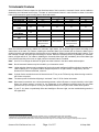
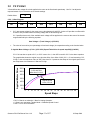
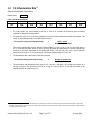
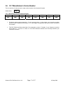
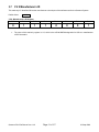
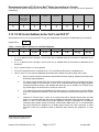
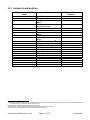
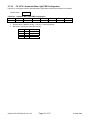
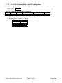
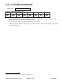
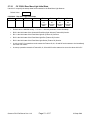
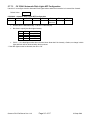
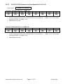
1
NMRA DCC Reference Manual for ® QSI Quantum Q1a and Q2 Equipped Locomotives Version 4.4.0 For Firmware Version 7 23 September 2008 Quantum DCC Ref Manual Ver 4.4.0 Page 2 of 257 23-Sept-2008 Table of Contents Table of Contents _______________________________________________________________________________________ 3 Digital Command Control Explained ________________________________________________________________________ 9 This Manual ___________________________________________________________________________________________ 10 1 Locomotive Operation in DCC _______________________________________________________________________ 11 1.1 Getting Started ___________________________________________________________________________________________11 1.2 Basic Throttle and Direction Control _________________________________________________________________________11 Locomotive Directional States ________________________________________________________________________________11 1.3 Throttle Control Modes ____________________________________________________________________________________12 1.5 Function Keys ___________________________________________________________________________________________13 1.5.1 Common Feature Function Key Assignments __________________________________________________________________13 1.6 Automatic Features _________________________________________________________________________________________14 1.7 Horn/Whistle and Bell Buttons (F2 Key and F1 Key) ____________________________________________________________15 1.8 Coupler and Coupler Crash Sounds (F3 Key)__________________________________________________________________15 1.9 Sound-of-Power™ ________________________________________________________________________________________16 1.10 Dynamic Brakes (F5 Key) __________________________________________________________________________________16 1.11 Doppler Shift (F6 in Forward and Reverse) ____________________________________________________________________17 1.11.1 Horn Button Method _____________________________________________________________________________________17 1.11.2 F6 Doppler Shift Operation Method _________________________________________________________________________17 1.12 Squealing Brakes and Flanges (F7 in Forward or Reverse) ______________________________________________________18 1.13 Air Brakes (F7 in Forward or Reverse) _______________________________________________________________________18 1.14 Audio Mute (F8 Key) ______________________________________________________________________________________19 1.15 Heavy Load (F9 in Forward or Reverse) ______________________________________________________________________19 1.16 Status Report (F10) _______________________________________________________________________________________20 1.17 Alternate Horn Selection (F11) ______________________________________________________________________________20 1.18 Three Stages of Shut Down: Disconnect, Standby and Total Shut Down (F9 in Neutral)_______________________________21 Stage One: Disconnect ________________________________________________________________________________________21 Stage Two: Standby __________________________________________________________________________________________21 Stage Three: Total Shut Down __________________________________________________________________________________21 1.19 Start Up (F6in Neutral)_____________________________________________________________________________________23 Start Up from Disconnect ______________________________________________________________________________________23 Start Up from Standby_________________________________________________________________________________________23 Start Up from Total Shut Down __________________________________________________________________________________23 1.20 Function Key Operation in Neutral___________________________________________________________________________23 2 Programming Configuration Variables ________________________________________________________________ 24 2.1 Service Mode Programming ________________________________________________________________________________24 2.2 Operations Mode Programming _____________________________________________________________________________25 2.3 List of CV’s Supported by Quantum Locomotives ______________________________________________________________26 3 CV’s 1-29: NMRA Standard CV’s _____________________________________________________________________ 31 3.1 CV 1 Primary Address Control ______________________________________________________________________________31 Quantum DCC Ref Manual Ver 4.4.0 Page 3 of 257 23-Sept-2008 3.2 CV 2 V-Start _____________________________________________________________________________________________32 3.3 CV 3 Acceleration Rate ____________________________________________________________________________________33 3.4 CV 4 Deceleration Rate ____________________________________________________________________________________34 3.5 CV 5 V-High _____________________________________________________________________________________________35 3.6 CV 7 Manufacturer’s Version Number ________________________________________________________________________37 3.7 CV 8 Manufacturer’s ID ____________________________________________________________________________________38 3.8 CV 11 Packet Time-Out Value _______________________________________________________________________________39 3.9 CV 17, 18 Extended Address _______________________________________________________________________________40 3.9.1 Entering Extended Address into CV 17 and CV 18 Directly: _______________________________________________________40 3.10 CV 19 Consist Address ____________________________________________________________________________________43 3.11 CV 21 Consist Address Active for F1-F8 ______________________________________________________________________44 3.12 CV 22 Consist Address Active for FL and F9-F12 ______________________________________________________________45 3.13 CV 23 Acceleration Adjustment _____________________________________________________________________________47 3.14 CV 24 Deceleration Adjustment _____________________________________________________________________________48 3.15 CV 25 Quantum Speed Table Selection _______________________________________________________________________49 Additional Information for the Curious Regarding QSI Speed Curves: ____________________________________________________49 3.16 CV 29 Configuration Data __________________________________________________________________________________51 4 CV’s 33-46: Output Locations________________________________________________________________________ 54 4.1 Overview ________________________________________________________________________________________________54 4.2 CV 33 Output Location for FL(f) _____________________________________________________________________________56 4.3 CV 34 Output Location for FL(r) _____________________________________________________________________________58 4.4 CV 35 Output Location for F1 _______________________________________________________________________________60 4.5 CV 36 Output Location for F2 _______________________________________________________________________________62 4.6 CV 37 Output Location for F3 _______________________________________________________________________________64 4.7 CV 38 Output Location for F4 _______________________________________________________________________________66 4.8 CV 39 Output Location for F5 _______________________________________________________________________________68 4.9 CV 40 Output Location for F6 _______________________________________________________________________________70 4.10 CV 41 Output Location for F7 _______________________________________________________________________________72 4.11 CV 42 Output Location for F8 _______________________________________________________________________________74 4.12 CV 43 Output Location for F9 _______________________________________________________________________________76 4.13 CV 44 Output Location for F10 ______________________________________________________________________________78 4.14 CV 45 Output Location for F11 ______________________________________________________________________________80 4.15 CV 46 Output Location for F12 ______________________________________________________________________________82 5 CV’s 49-64: QSI Unique CV’s ________________________________________________________________________ 84 5.1 Overview ________________________________________________________________________________________________84 5.2 CV 49 QSI Primary Index ___________________________________________________________________________________86 5.3 CV 50 QSI Secondary Index ________________________________________________________________________________87 5.4 CV 51.PI QSI System Sound Control _________________________________________________________________________88 5.4.1 CV 51.0 Operations Mode System Volume (PI = 0) __________________________________________________________88 5.4.2 CV 51.1 Operations Mode Mute Volume (PI = 1) ____________________________________________________________89 5.4.3 CV 51.2 Special Sound Effects Enable (PI = 2) _____________________________________________________________90 Quantum DCC Ref Manual Ver 4.4.0 Page 4 of 257 23-Sept-2008 5.4.4 CV 51.5 Automatic Mute Timeout Value (PI = 5) ____________________________________________________________93 5.5 CV 52.PI QSI Individual Sound Volume Control ________________________________________________________________94 5.5.1 Individual Sound Identifiers _____________________________________________________________________________95 5.6 CV 53.PI.SI Output Feature Assignment ______________________________________________________________________96 5.6.1 QSI Feature Identification Numbersused with CV 53 _________________________________________________________98 5.6.2 CV 53 Factory Default Settings _________________________________________________________________________103 5.7 CV 55.PI.SI QSI Feature Configuration ______________________________________________________________________104 5.7.1 CV 55.3.SI Bell _____________________________________________________________________________________104 5.7.1.1 CV 55.3.0 Maximum Bell Index ______________________________________________________________________104 5.7.1.2 CV 55.3.1 Bell Select ______________________________________________________________________________105 5.7.3 CV 55.70.SI Headlight________________________________________________________________________________106 5.7.3.1 CV 55.70.0 Headlight Initial State ____________________________________________________________________107 5.7.3.2 CV 55.70.1 Automatic Headlight Configuration __________________________________________________________108 5.7.3.3 CV 55.70.10 Headlight Dim Intensity __________________________________________________________________109 5.7.3.4 CV 55.70.12 Headlight Max Intensity__________________________________________________________________110 5.7.3.5 CV 55.70.SI Headlight Examples_____________________________________________________________________111 5.7.4 CV 55.73.SI Reverse Light ____________________________________________________________________________112 5.7.4.1 CV 55.73.0 Reverse Light Initial State _________________________________________________________________113 5.7.4.2 CV 55.73.1 Automatic Reverse Light Configuration_______________________________________________________114 5.7.4.3 CV 55.73.10 Reverse Light Dim Intensity ______________________________________________________________115 5.7.4.4 CV 55.73.12 Reverse Light Max Intensity ______________________________________________________________116 5.7.4.5 CV 55.73.SI Reverse Light Examples _________________________________________________________________117 5.7.5 CV 55.76.SI Mars Light _______________________________________________________________________________118 5.7.5.1 CV 55.76.0 Mars Light Initial State____________________________________________________________________119 5.7.5.2 CV 55.76.1 Automatic Mars Light FWD Configuration_____________________________________________________120 5.7.5.3 CV 55.76.2 Automatic Mars Light NFF Configuration _____________________________________________________121 5.7.5.4 CV 55.76.3 Automatic Mars Light REV Configuration _____________________________________________________122 5.7.5.5 CV 55.76.4 Automatic Mars Light NFR Configuration _____________________________________________________123 5.7.5.6 CV 55.76.6 Mars Light Strobe Period _________________________________________________________________124 5.7.5.7 CV 55.76.10 Mars Light Dim Intensity _________________________________________________________________125 5.7.5.8 CV 55.76.11 Mars Light Min Intensity _________________________________________________________________126 5.7.5.9 CV 55.76.12 Mars Light Max Intensity _________________________________________________________________127 5.7.5.10 CV 55.76.13 Mars Light Mid Intensity _________________________________________________________________128 5.7.5.11 CV 55.76.SI Mars Light Examples ____________________________________________________________________129 5.7.6 CV 55.80.SI Rear Mars Light___________________________________________________________________________130 5.7.6.1 CV 55.80.0 Rear Mars Light Initial State _______________________________________________________________131 5.7.6.2 CV 55.80.1 Automatic Rear Mars Light FWD Configuration ________________________________________________132 5.7.6.3 CV 55.80.2 Automatic Rear Mars Light NFF Configuration _________________________________________________133 5.7.6.4 CV 55.80.3 Automatic Rear Mars Light REV Configuration_________________________________________________134 5.7.6.5 CV 55.80.4 Automatic Rear Mars Light NFR Configuration_________________________________________________135 5.7.6.6 CV 55.80.6 Rear Mars Light Strobe Period _____________________________________________________________136 5.7.6.7 CV 55.80.10 Rear Mars Light Dim Intensity_____________________________________________________________137 5.7.6.8 CV 55.80.11 Rear Mars Light Min Intensity _____________________________________________________________138 5.7.6.9 CV 55.80.12 Rear Mars Light Max Intensity_____________________________________________________________139 5.7.6.10 CV 55.80.13 Rear Mars Light Mid Intensity _____________________________________________________________140 5.7.6.11 CV 55.80.SI Rear Mars Light Examples________________________________________________________________141 5.7.7 CV 55.84.SI Ditch Lights ______________________________________________________________________________142 5.7.7.1 CV 55.84.0 Ditch Lights Initial State___________________________________________________________________143 5.7.7.2 CV 55.84.1 Automatic Ditch Lights FWD Configuration____________________________________________________144 5.7.7.3 CV 55.84.2 Automatic Ditch Lights NFF Configuration ____________________________________________________145 5.7.7.4 CV 55.84.3 Automatic Ditch Lights REV Configuration ____________________________________________________146 5.7.7.5 CV 55.84.4 Automatic Ditch Lights NFR Configuration ____________________________________________________147 5.7.7.6 CV 55.84.5 Ditch Lights Strobe Hold Time _____________________________________________________________148 5.7.7.7 CV 55.84.6 Ditch Lights Strobe Period ________________________________________________________________149 5.7.7.8 CV 55.84.10 Ditch Lights Dim Intensity ________________________________________________________________150 5.7.7.9 CV 55.84.12 Ditch Lights Max Intensity ________________________________________________________________151 5.7.7.10 CV 55.84.SI Ditch Lights Examples ___________________________________________________________________152 5.7.8 CV 55.88.SI Rear Ditch Lights__________________________________________________________________________153 Quantum DCC Ref Manual Ver 4.4.0 Page 5 of 257 23-Sept-2008 5.7.8.1 CV 55.88.0 Rear Ditch Lights Initial State ______________________________________________________________154 5.7.8.2 CV 55.88.1 Automatic Rear Ditch Lights FWD Configuration _______________________________________________155 5.7.8.3 CV 55.88.2 Automatic Rear Ditch Lights NFF Configuration ________________________________________________156 5.7.8.4 CV 55.88.3 Automatic Rear Ditch Lights REV Configuration________________________________________________157 5.7.8.5 CV 55.88.4 Automatic Rear Ditch Lights NFR Configuration________________________________________________158 5.7.8.6 CV 55.88.5 Rear Ditch Lights Strobe Hold Time _________________________________________________________159 5.7.8.7 CV 55.88.6 Rear Ditch Lights Strobe Period ____________________________________________________________160 5.7.8.8 CV 55.88.10 Rear Ditch Lights Dim Intensity____________________________________________________________161 5.7.8.9 CV 55.88.12 Rear Ditch Lights Max Intensity____________________________________________________________162 5.7.8.10 CV 55.88.SI Rear Ditch Lights Examples_______________________________________________________________163 5.7.9 CV 55.92.SI Overhead Beacon Light ____________________________________________________________________164 5.7.9.1 CV 55.92.0 OHBL Initial State _______________________________________________________________________165 5.7.9.2 CV 55.92.6 OHBL Period ___________________________________________________________________________166 5.7.9.3 CV 55.92.11 OHBL Min Intensity _____________________________________________________________________167 5.7.9.4 CV 55.92.12 OHBL Max Intensity ____________________________________________________________________168 5.7.10 CV 55.96.SI Rear Overhead Beacon Light ________________________________________________________________169 5.7.10.1 CV 55.96.0 Rear OHBL Initial State___________________________________________________________________170 5.7.10.2 CV 55.96.6 Rear OHBL Period ______________________________________________________________________171 5.7.10.3 CV 55.96.11 Rear OHBL Min Intensity ________________________________________________________________172 5.7.10.4 CV 55.96.12 Rear OHBL Max Intensity ________________________________________________________________173 5.7.11 CV 55.100.SI Front Number Board Lights_________________________________________________________________174 5.7.11.1 CV 55.100.0 Front Number Board Lights Initial State _____________________________________________________175 5.7.11.2 CV 55.100.1 Automatic Front Number Board Lights Configuration ___________________________________________176 5.7.11.3 CV 55.100.SI Front Number Board Lights Examples______________________________________________________177 5.7.12 CV 55.102.SI Rear Number Board Lights _________________________________________________________________178 5.7.12.1 CV 55.102.0 Rear Number Board Lights Initial State______________________________________________________179 5.7.12.2 CV 55.102.1 Automatic Rear Number Board Lights Configuration ___________________________________________180 5.7.12.3 CV 55.102.SI Rear Number Board Lights Examples ______________________________________________________181 5.7.13 CV 55.104.SI Front Marker Lights_______________________________________________________________________182 5.7.13.1 CV 55.104.0 Front Marker Lights Initial State ___________________________________________________________183 5.7.13.2 CV 55.104.1 Automatic Front Marker Lights Configuration _________________________________________________184 5.7.13.3 CV 55.104.SI Front Marker Lights Examples____________________________________________________________185 5.7.14 CV 55.106.SI Rear Marker Lights _______________________________________________________________________186 5.7.14.1 CV 55.106.0 Rear Marker Lights Initial State____________________________________________________________187 5.7.14.2 CV 55.106.1 Automatic Rear Marker Lights Configuration _________________________________________________188 5.7.14.3 CV 55.106.SI Rear Marker Lights Examples ____________________________________________________________189 5.7.15 CV 55.116.SI Front Cab Lights _________________________________________________________________________190 5.7.15.1 CV 55.116.0 Front Cab Lights Initial State______________________________________________________________191 5.7.15.2 CV 55.116.1 Automatic Front Cab Lights Configuration ___________________________________________________192 5.7.15.3 CV 55.116.SI Front Cab Lights Examples ______________________________________________________________193 5.7.16 CV 55.118.SI Rear Cab Lights _________________________________________________________________________194 5.7.16.1 CV 55.118.0 Rear Cab Lights Initial State ______________________________________________________________195 5.7.16.2 CV 55.118.1 Automatic Rear Cab Lights Configuration____________________________________________________196 5.7.16.3 CV 55.118.SI Rear Cab Lights Examples ______________________________________________________________197 5.7.17 CV 55.136.SI Multiple Automatic Lights #1 ________________________________________________________________198 5.7.18 CV 55.137.SI Multiple Automatic Lights #2 ________________________________________________________________199 5.7.19 CV 55.138.SI Multiple Automatic Lights #3 ________________________________________________________________200 5.7.20 CV 55.154.SI Grade Crossing Horn Signal ________________________________________________________________201 5.7.21 CV 55.178.SI Status Report ___________________________________________________________________________204 5.7.21.1 CV 55.178.0 Status Report Configuration ______________________________________________________________204 5.8 CV 56.PI.SI QSI Configuration ________________________________________________________________________________205 5.8.1 CV 56.0: QSI System Configuration (PI = 0) _______________________________________________________________205 5.8.2 CV 56.4: QSI Throttle Mode (PI = 4) _____________________________________________________________________207 5.8.3 CV 56.5: Regulated Throttle Control (RTC) Minimum Back EMF (PI = 5) ________________________________________209 5.8.4 CV 56.9: BEMF to Scale MPH Trim (PI = 9) _______________________________________________________________210 5.8.4.1 Calibrating BEMF to SMPH _________________________________________________________________________210 Using a Commerical Speedometer_________________________________________________________________________210 Using a Stopwatch _____________________________________________________________________________________211 Using the Locomotive’s Odometer _________________________________________________________________________211 Quantum DCC Ref Manual Ver 4.4.0 Page 6 of 257 23-Sept-2008 5.8.5 CV 56.10: Speed Step to Scale MPH Scale Factor (PI = 10) __________________________________________________213 5.8.6 CV 56.12: Chuff Interval Scale Factor (PI = 12) ____________________________________________________________214 5.8.6 CV 56.13: Chuff Interval Trim (PI = 13) ___________________________________________________________________215 5.8.7 CV 56.18-21.SI: Quantum PID Parameters________________________________________________________________216 5.8.7.1 CV 56.18.SI PID Parameters for Very Slow Speed (PI=18, SI = 0,2) _______________________________________________216 5.8.7.2 CV 56.19.SI PID Parameters for Slow Speed (PI=19, SI = 0,2) _____________________________________________217 5.8.7.3 CV 56.20.SI PID Parameters for Medium Speed (PI=20, SI = 0,2) ___________________________________________218 5.8.7.4 CV 56.21.SI PID Parameters for High Speed (PI=21, SI = 0,2)______________________________________________219 5.8.7.5 Setting PID Parameters for Quantum Equipped Model Locomotives: _________________________________________220 5.8.7.6 General Hints for Setting PID Parameters: _____________________________________________________________221 5.8.8 CV 56.24.SI: Wheel Diameter (PI = 24,SI = 0,1)____________________________________________________________222 5.8.9 CV 56.25.SI: Locomotive Scale (PI = 25,SI = 0,1) __________________________________________________________223 5.8.10 CV 56.32.0: Room Temperature (PI = 32,SI = 0) ___________________________________________________________224 5.8.10 CV 56.128: Reset to Factory Default (PI = 128) ____________________________________________________________225 5.8.11 CV 56.129: Locomotive ID Access (PI = 129) ______________________________________________________________226 5.8.12 CV 56.254: About Quantum Decoder (PI = 254)____________________________________________________________228 5.8.13 CV 56.255: Play Build Information (PI = 255) ______________________________________________________________229 5.9 CV 58.1.SI Odometer _____________________________________________________________________________________230 5.9.1 Odometer Reset______________________________________________________________________________________230 5.9.2 Ops Mode Odometer Read Out ___________________________________________________________________________230 5.9.3 Service Mode Odometer Read Back________________________________________________________________________231 5.9.4 BEMF Odometer Mode (CV56.0 bit 5 = “0”)___________________________________________________________________231 5.9.5 CAM Odometer Mode (CV56.0 bit 5 = “1”) ___________________________________________________________________231 5.10 CV 62 QSI Control _______________________________________________________________________________________233 5.11 CV 64 CV Numeric Verbal Readout (Verbal CV Inquiry)_________________________________________________________236 6 CV’s 66-95: NMRA Standard CV’s ___________________________________________________________________ 237 6.1 CV 66 Forward Trim ______________________________________________________________________________________237 6.2 CV 67-94 User Defined Speed Table ________________________________________________________________________238 6.3 CV 95 Reverse Trim ______________________________________________________________________________________239 Appendix I ___________________________________________________________________________________________ 240 Recommended DCC Command Stations __________________________________________________________________________240 Appendix II A _________________________________________________________________________________________ 242 Programming a Long Address on Digitrax ________________________________________________________________________242 Appendix II B _________________________________________________________________________________________ 243 Programming a Long Address on North Coast Engineering (NCE) ____________________________________________________243 Appendix III __________________________________________________________________________________________ 245 DCC Troubleshooting _________________________________________________________________________________________245 Operations Mode____________________________________________________________________________________________245 Service Mode Operation using the Program Track __________________________________________________________________247 Appendix IV __________________________________________________________________________________________ 248 Recommended Reading: _______________________________________________________________________________________248 Appendix V___________________________________________________________________________________________ 249 Application Notes: ____________________________________________________________________________________________249 Using DC Power Conversion for Block Signal Control _______________________________________________________________249 Appendix VI __________________________________________________________________________________________ 251 Binary, Hexadecimal, Decimal Conversions _______________________________________________________________________251 Appendix VII__________________________________________________________________________________________ 252 Quantum DCC Ref Manual Ver 4.4.0 Page 7 of 257 23-Sept-2008 Rights and Obligations ________________________________________________________________________________________252 Index ________________________________________________________________________________________________ 253 Quantum DCC Ref Manual Ver 4.4.0 Page 8 of 257 23-Sept-2008 Digital Command Control Explained Digital Command Control (DCC) is the standard adopted by the National Model Railroad Association (NMRA) in 19941 to allow compatible operation of all locomotives and Command Stations regardless of manufacturer. DCC differs from Analog control in that DCC applies full voltage to the track at all times and controls the speed and functions of different locomotives by addressing each locomotive separately using assigned locomotive ID numbers. Because each locomotive can be addressed separately, you can independently control speed, lights, and sounds on different locomotives on the same powered track. DCC provides features and opportunities that are usually not available under conventional Analog Control2, but does require you to commit to a new and more complex operating system. All Quantum equipped locomotives operate using NMRA DCC control. The three most common locomotives are Steam, Diesel and Electric, although others, such as trolleys, powered commuter cars, subways, etc. can be operated under DCC as well. Quantum equipped locomotives have been designed to operate directly out of the box under NMRA standards for either conventional Analog DC operation or Digital Command Control. There are no switches in the locomotive that need to be set to select the type of control system. The Quantum System responds directly to the type of signal on the track. 1 The Electrical and Communication Standards were adopted by the NRMA in Portland OR in July, 1994. The basic Recommended Practices (RP’s) were accepted in 1995 in Atlanta Georgia and the Service Mode RP’s were established in 1996. 2 Quantum systems use an advanced Analog control system called QARC™ (Quantum Analog Remote Control) Technology that does provide many of the same features available in DCC. See the Quantum Analog Reference Manual for details. Quantum DCC Ref Manual Ver 4.4.0 Page 9 of 257 23-Sept-2008 This Manual This manual is divided into seven parts: • The first section summarizes how to operate your Quantum locomotive in DCC. Read this and you will quickly have your locomotive up and running. • The second section summarizes the programming of Configuration Variables (CV’s). Read this when you are ready to customize your locomotive’s operation. • The third section describes in detail NMRA standard CV’s supported by Quantum locomotives. Skim over this to get a general idea of what it contains. You will often refer to it when you want to solve a particular problem. • The fourth section outlines in excruciating detail the NMRA standard CV’s which assign outputs to function keys. Normally you do not have to be concerned with these CV’s, but sometimes this section is important, for example if you ever have to configure your locomotive to operate with a DCC controller having a small number of function keys. • The fifth section describes in detail CV’s that are unique to Quantum locomotives. Skim over this to get an idea of the degree of flexibility built into Quantum locomotives. Refer to this section whenever you want to customize volume levels, change the features that are assigned to function key outputs, configure the behavior of these features, or tweak your locomotive’s running performance. • The sixth section describes in detail additional NMRA standard CV’s that you may find useful if you want to fine-tune your locomotive’s running performance. • The appendices describe operation with different DCC Digital Command Stations, troubleshooting and Applications Notes. Most operations of Quantum equipped locomotives, such as turning the Bell on and off, changing direction, blowing a Horn or a Whistle, are the same across all locomotive types. Special operations for different types of Quantum equipped locomotives are described in the Operation Manuals that come with the locomotives. Any special features included in this Reference Manual will be described in sidebars or notes. Please Note This reference manual completely describes all features currently available in DCC when operating a Quantum locomotive that has Q1a or Q2 Version 7 firmware. If your locomotive has Version 6 or earlier firmware, use the Quantum DCC Reference Manual Version 3. To determine you software version read the contents of CV 7 (In Ops Mode, set CV 64 to 7 and hear verbal response). Many of the new features described in version 4.1 of this manual are currently available only with Q2 firmware supporting O-Scale and G-Scale locomotives and with Q2 Quantum Revolution firmware. As new Quantum locomotives are introduced, they may have features not found in earlier locomotives. Check the Operation Manual that came with your locomotive to determine which features apply to your locomotive. This document will evolve over time as new information is added to keep it as complete and current as possible. Although reading the first section, “Locomotive Operation in DCC”, will allow you to begin operating your Quantum locomotive immediately, the purpose of this manual is not to teach you how to use DCC. We assume that you already have the working knowledge and experience to operate the different DCC features and program CV’s. If you are just getting started in DCC, there are several books listed in the appendices to instruct you in the operation of DCC layouts, turnouts, accessories, programming Configuration Variables (CV’s), etc. Quantum DCC Ref Manual Ver 4.4.0 Page 10 of 257 23-Sept-2008 1 Locomotive Operation in DCC 1.1 Getting Started Although DCC operation can be very complex, it does not have to be. Your Quantum locomotive is factory configured to operate the common and more popular features. The following brief instructions will get you up and running quickly. To start operating your Quantum equipped locomotive immediately: 1) Select locomotive number 3 2) Set your controller to 128 (preferred) or 28 (acceptable) speed step range 3 3) Start your locomotive by turning up the throttle 1.2 Basic Throttle and Direction Control When you turn up the throttle, the locomotive starts moving and produces sounds appropriate to its moving state. The Headlight, Mars Light, and Reverse Light change intensity depending on the direction of movement. When you reduce the throttle setting to zero, the locomotive comes to a complete stop and automatically enters Neutral. You will hear special background sounds appropriate to its resting state. If the locomotive was moving Forward, the Headlight (or operating Mars Light) dims when it stops and enters Neutral. This was common practice for prototype locomotives under Rule 174. You will hear a Short Air Let-off whenever the locomotive enters Neutral. If you leave your Steam locomotive in Neutral for at least 25 seconds and then slowly turn up the throttle, the locomotive plays Cylinder Cocks sounds as it starts moving. The Cylinder Cocks sounds automatically terminate after 16 repetitions or when the locomotive reaches a speed greater than 12 smph. The direction of your locomotive changes when you press the direction key. If the locomotive was moving at the time you pressed the direction button, the locomotive slows at a speed determined by the deceleration setting in CV 4, come to a complete stop and then accelerates in the other direction as determined by the CV 3 acceleration setting. CV 3 and CV 4 are described in the section “Programming Configuration Variables”. Locomotive Directional States Quantum locomotives have four distinct Directional States: Forward (FWD): If the locomotive is set to the Forward Direction and is moving, it is in the “Forward” state. Neutral from Forward (NFF): If the locomotive is set to the Forward Direction, and the throttle is turned down to zero speed step and the locomotive is stopped, it will be in a Neutral State called “Neutral from Forward”. Reverse (REV): If the locomotive is set to the Reverse Direction and is moving, it is in the “Reverse” state. Neutral from Reverse (NFR): If the locomotive is set to the Reverse Direction, and the throttle is turned down to zero speed step and the locomotive is stopped, it will be in a Neutral State called “Neutral from Reverse”. 3 If you set your controller to 14 speed-step operation without reconfiguring your Quantum system to the same speed steps in CV 29, your Directional Lighting will not operate correctly. 4 Rule 17, followed by prototype railroads, states: The headlight will be displayed to the front of every train by night, but must be dimmed or concealed when a train turns out to meet another and the entire train has stopped clear of main track, or is standing to meet trains at the end of double track or at junctions. Quantum DCC Ref Manual Ver 4.4.0 Page 11 of 257 23-Sept-2008 1.3 Throttle Control Modes There are four ways your locomotive can respond to your throttle. • Standard Throttle Control (STC) :: Under STC, the percentage of full power applied to the motor is directly related to the throttle setting (speed step). Since the power to the motor is constant for a given throttle setting, the locomotive’s speed varies depending on the load. The locomotive may easily stall at low speeds from minor gear binding, turnouts, and curves. • Calibrated Speed Control (CSC): Under CSC, the power applied to the motor is varied to maintain constant speed regardless of varying load conditions. The throttle setting (using 128 speed steps specifies the locomotive’s speed in 1 smph (scale miles per hour) increments. If your throttle is set at 35, the locomotive tries to maintain 35 smph on level track, up hill, and down hill. If locomotives in a consist differ even slightly in speed calibration, some of the locomotives do all the work while the other locomotives are dragged along. • Load Compensated BEMF Speed Control (BEMFSC): Under BEMFSC, each speed step corresponds to a target BEMF value. The locomotive adjusts the power applied to the motor so that the locomotive’s measured BEMF matches the target BEMF. • Regulated Throttle Control (RTC) RTC combines the best of STC and Speed Control. It is the preferred method when multiple heading Quantum locomotives together because it automatically equalizes power between locomotives. Like Speed Control, RTC allows you to run your locomotive at very slow speeds without concern that it will abruptly stop from minor impediments such as misaligned track joints, tight curves, or rough switches. RTC operates your locomotive as though it has huge mass; your locomotive will resist changes in speed once it is moving and will resist starting up quickly if at rest. For further explanation of these four modes, see CV 56.4: QSI Throttle Mode. The default mode is RTC. You can change to STC using CV 56.4. Quantum equipped locomotives will produce labored sounds under acceleration and lighter non-labored sounds under deceleration. The level of labored sounds is proportional to the value of CV 3 plus CV23, and of CV 4 plus CV24 and how much the throttle is increased or decreased. Diesel locomotives produce louder motor sounds under acceleration and softer motor sounds under deceleration. Steam locomotives produce louder chuffs under acceleration and softer chuffs under deceleration. Important Legal Notice BEMF Speed Control and Calibrated Speed Control under DCC operation are not included in your Q1a or Q2 equipped locomotive model. These functions have been declined by model railroad importers of Quantum equipped locomotives because of threats of litigation by Mike’s Train House. QSI believes the claim by Mikes Train House is unfounded because these control features were developed by QSI and others and were in use long before Mike’s Train House claims to have invented them. QSI does not believe that Quantum Sound System infringes any MTH patent. Quantum DCC Ref Manual Ver 4.4.0 Page 12 of 257 23-Sept-2008 1.5 Function Keys Quantum decoders support the 0-12 Function Key standard as now accepted by the NMRA; the old 0-8 standard is not supported. 1.5.1 Common Feature Function Key Assignments The following table lists features that have been pre-assigned to your DCC Function Keys for common operation across the different types of Quantum locomotives. Check the Operation Manual that comes with your locomotive to see which of these common features are offered or what additional custom features have been included. These common features are described in detail in the following sections. Notice that some keys operate different features in Forward/Reverse than in Neutral. F-Key FL(f)5 F5 F6 F7 FWD/REV Headlight,, Reverse Light, and Hazard Light Directional Lighting Headlight, Reverse Light, and Hazard Light Directional Lighting Bell on/off (if assigned7) Horn/Whistle w/ Doppler Shift Coupler Crash/Coupler Fire Steam Blower Hiss/ Diesel Fans and Louvers/ Electric Cooling Fans Dynamic Brakes Doppler Shift Squealing Brakes/Flanges and Air Brakes F8 F9 Audio Mute Heavy Load8 F10 F11 Status Report (SMPH) Alternate Horn Selection Number Board or Marker Lights on/off Automatic Cab Lights FL(r)6 F1 F2 F3 F4 F12 NFF/NFR Headlight, Reverse Light, and Hazard Light Directional Lighting Headlight, Reverse Light, and Hazard Light Directional Lighting Bell on/off (if assigned) Horn/Whistle Coupler Arm (Enable) or Coupler Fire Steam Blower Hiss/ Diesel Fans and Louvers/ Electric Cooling Fans Dynamic Brakes Locomotive Start Up Steam Cylinder Cocks Arm Diesel Long Air Let-off Electric Long Air Let-off Gas Turbine/Diesel Transition Audio Mute Shut Down9: Disconnect-Standby-Total Shut Down Status Report (ID’s, etc.) Alternate Horn Selection/ Number Board or Marker Lights on/off Automatic Cab Lights 5 The FL Key is labeled “F0”, “Headlights” “Lights” or “Directional Lighting” on some DCC controllers. 6 FL(f) and FL(r) activate/deactivate the automatic behavior of the Headlight, Reverse Light, and Hazard Directional Lighting regardless of which direction the train is moving. 7 If the prototype did not have a bell, the bell feature is not assigned to F1 and no other feature is assigned in its place. 8 Early Q1 BLI and Lionel locomotives used F9 for Cruise Control, which was only available on locomotives equipped with Speed Control. 9 There are three stages to Shut Down. You double click the F9 key to advance to each stage. Quantum DCC Ref Manual Ver 4.4.0 Page 13 of 257 23-Sept-2008 1.6 Automatic Features Automatic Quantum Features depend on the directional state of the locomotive. Automatic Control can be enabled or disabled by their indicated function keys. The state of each Automatic feature in each direction is shown in the table below for all locomotive types including steam, diesel and electric. Feature Headlight Rear Tender Light Mars Light Ditch Lights Number Board Lights Marker Lights Cab Lights Function Key F0 or FL F0 or FL F0 or FL F0 or FL Forward Bright Dim11 Strobing On Neutral from Forward Dim10 Dim Steady On Off Reverse Dim Bright Steady On Off Neutral from Reverse Dim Dim Steady On Off F11 On On On On F11 F12 On Off after 15 seconds On On after 10 seconds. On Off after 15 seconds On On after 10 seconds. Steam Blowers F4 Off after 10 seconds. On after 10 seconds. Off after 10 seconds. On after 10 seconds. Vents & Cooling Fans Cylinder Cocks12 F4 On after 20 seconds. Off after 10 seconds. On After 20 seconds. Off after 10 seconds. F7 If armed, plays Cylinder Cocks for 16 times or until speed exceeds 12 smph. Cylinder Cocks armed after 25 seconds. If armed, plays Cylinder Cocks for 16 times or until speed exceeds 12 smph. Cylinder Cocks armed after 25 seconds. When an indicated function key enables an “automatic” light feature, the associated lights operate according to the states shown in the table. For instance, enabling the Automatic Mars Light in Neutral will not cause the Mars Light to strobe since their automatic behavior would have them at a steady-on setting in that directional state; however, it you then entered Forward, the Mars Light would begin to strobe. When an indicated function key disables an “automatic” feature, all lights will be off. For instance, disabling the “Automatic Mars Light” will immediately shut off the Mars Light in any direction and they will not turn on again until the automatic feature is enabled. Note: Use CV 55 to change the behavior of lights from what is shown in the above table and description. Note: Not all automatic features may be included in your locomotive model. Note: Lights and other features can be assigned to function keys and configured to different kinds of operation and initial conditions in CV 53 (Output Feature Assignment) and CV 55 (QSI Feature Configuration). See the Quantum DCC Reference Manual, version 4. Note: Cylinder Cocks can also be armed in Neutral with the F7 key or the F6 Start Up key without having to wait for the 25 time out period. Note: The start up state for directional lighting is “activated”. See CV 55 for further information. Note: Most steam locomotives use a steam-powered generator, called a Dynamo, to supply electricity to the lights. When the lighting system is turned on, the brightness of the headlight increases slowly as the steam generator revs up to full power. Check your Operation Manual to see if your steam model has a Dynamo. Note: If your FL key does not predictably affect the Headlight or Reverse Light, see the troubleshooting section in the appendices. 10 If your locomotive has the Mars Light, the Headlight will be off (instead of “Dim”) in all states except Forward where it will be Bright. 11 Most Quantum 1 and Q1a Reverse Lights cannot be dimmed; they only have bright and off settings. In these cases, “Dim” is equivalent to “Off”. 12 Cylinder Cocks arming after Start Up and/or after 25 seconds in Neutral can be set using CV 51.2. The settings in this CV apply to both Analog and DCC operation. Quantum DCC Ref Manual Ver 4.4.0 Page 14 of 257 23-Sept-2008 1.7 Horn/Whistle and Bell Buttons (F2 Key and F1 Key) Some DCC controllers have separate horn/whistle and bell buttons, in addition to Function Keys assigned to horn/whistle and bell operation. The bell is usually assigned to F1, and the horn is usually assigned to F2. The F2 key behaves differently than the Horn button. • Pressing F2 and releasing it will cause the horn/whistle to come on and stay on until you press F2 again. • Pressing the Horn button will blow the horn/whistle only as long as you hold the button down. There is no difference in operation between the Bell button and its corresponding function key. Pressing F1 and releasing it will cause the bell to come on and stay on until you press F1 again. Horns and whistles have start up and shut down effects and a short hoot record for short duration horn/whistle blasts. Some models have an additional fancy ending (playing the horn/whistle). On these models, you can activate the fancy ending by tapping the horn button at the end of the horn blast. If your locomotive is equipped with Ditch Lights, they will automatically strobe when the horn is being blown, and will continue to strobe until five seconds after the horn signal has stopped13. With Diesel, Electric, and Gas Turbine models, since the prototype horn uses compressed air, you will hear Air Pump sounds turn on after the Horn is operated. Note: If your DCC controller has assigned the Bell to F3, you can reassign your Quantum decoder’s F3 to the bell output (see CV 37). Remember to reassign the F1 Function to some other output besides 3 (see CV 35). 1.8 Coupler and Coupler Crash Sounds (F3 Key) There are two ways to use the F3 key. 1) In Forward or Reverse, as your locomotive is moving to couple up to a string of cars, press F3 to trigger the crashing sound of a locomotive coupling. Press F3 again as the locomotive is moving out to produce the same sound as the slack is taken up in the cars. 2) Press F3 in Neutral to produce uncoupling sounds as you disconnect cars over uncoupler magnets. Press F3 once to produce the sound of the lift bar and coupling pin being raised. This first press also arms the uncoupling sound effect. Press F3 again while moving or in Neutral to produce the sound of the coupler knuckle opening and the air-lines parting. If you armed the Coupler in Neutral and your locomotive is now in Forward or Reverse, pressing F3 produces the sound of the coupler opening. Thereafter, as the locomotive continues in Forward or Reverse, pressing F3 will produce coupler crash sounds. 13 The hold time for strobing Ditch Lights after the horn button is released can be set in CV 55.84.5. Quantum DCC Ref Manual Ver 4.4.0 Page 15 of 257 23-Sept-2008 1.9 Sound-of-Power™ If CV 3, or CV 23 and CV 4, or CV 24 has been set to non-zero positive values, your locomotive will produce additional labored engine sounds under acceleration and lighter engine sounds under deceleration. The level of labored sounds is proportional to the values for these four CV’s, and how much the throttle is increased or decreased. Laboring is different for the three primary types of locomotives: Diesel Motor RPM: Quantum has all eight diesel-motor throttle “notches” found on prototype locomotives. As you increase the throttle, you will hear the RPM’s increase for every increase in ten speed steps (at 128 speed step setting). Idle is considered Notch 0 and occurs for speed step 0. Notch 1 ranges from 1 to 10, Notch 2 from 11 to 20, Notch 3 from 21 to 30, etc. If your controller has an option to increment or decrement your throttle set setting by ten speed steps, it is very easy and predicable to set your notch value. Steam Exhaust: Under acceleration the steam exhaust is labored and loud and under decelerating, the steam exhaust is lighter. Also, when starting out after an extended period in Neutral (over 25 seconds), you will hear steam and water vented from the Cylinder Cocks when it starts out. The Cylinder Cocks will vent 16 times or until speed exceeds 12 smph. Electric Traction Motors: Under acceleration, hear the traction motors rev up and strain as the Electric locomotive gains full speed. Under deceleration, the traction motors are not labored and rev down as the locomotive slows. 1.10 Dynamic Brakes (F5 Key) Diesel Locomotives: The prototype Dynamic Brakes, found on most diesels, cause the train to slow down by using the traction motors in generator mode. This helps dissipate the energy of a moving train by applying electrical power from the traction motors to a large air-cooled resistor load in the locomotive. These resistor grids can get quite hot and require cooling by fans located on the roofs of the locomotives. • Pressing F5 in Forward/Reverse will set the Diesel Motor sound to idle at the lowest Sound of Power setting and turn on the powerful Dynamic Brake Cooling Fans. • Pressing F5 in Neutral does not turn the Dynamic Brake Fans on unless the locomotive is in Disconnect (see F9 “Disconnect” below). Electric Locomotives: Early Electric locomotives did not have Dynamic Brakes. However, the Dynamic Brake function has been included to make Electric locomotives consistent with other Quantum equipped locomotives. • Pressing F5 in Forward/Reverse will set the Electric Traction Motor Sound-of-Power to the lowest setting allowing these early Electric locomotives to behave consistently14 with other locomotives that do have Dynamic Brake sounds in multiple unit Consists. • If an Electric locomotive does have Dynamic Brakes with resistor grids and cooling fans, the locomotive will behave in a similar manner to Diesels. Steam Locomotives: Prototype Steam locomotives do not have Dynamic Brake sounds. However, the Dynamic Brake function has been included to make Steam locomotives consistent with other Quantum equipped locomotives. • Pressing F5 in Forward/Reverse will set the Steam Exhaust Sound-of-Power to the lowest setting allowing the Steam locomotive to behave consistently15 with other locomotives that do have Dynamic Brake sounds in multiple unit Consists. The Dynamic Brakes feature automatically turns off when entering or leaving Neutral, or the speed of the locomotive drops below 8 smph, or if the throttle is turned up. The Dynamic Brakes cannot be turned on in Forward or Reverse unless the locomotive is traveling over 9 smph. 14 It would be inconsistent for the Electric Locomotive to be working at full Sound-of-Power while brakes are being applied in other locomotives within the same consist. 15 It would be inconsistent for the Steam Locomotives to be working at full Sound-of-Power while brakes are being applied in other locomotives within the same consist. Quantum DCC Ref Manual Ver 4.4.0 Page 16 of 257 23-Sept-2008 1.11 Doppler Shift (F6 in Forward and Reverse) There are two ways to initiate the Doppler Shift effect. 1.11.1 Horn Button Method16 1) If your controller has a horn button in addition to the F2 key, press the horn button to turn on the Horn/Whistle while the locomotive is moving towards you. 2) Wait at least one second while the Horn/Whistle is blowing 3) Release and re-press the horn button quickly so the Horn/Whistle does not shut off. You will hear the Horn/Whistle and other locomotive sounds increase in volume and shift in pitch as the locomotive passes by and then reduce in volume. 4) Release the horn button or continue blowing long and short blasts. Five to seven seconds after releasing the horn button, the sounds will gradually return to normal. 1.11.2 F6 Doppler Shift Operation Method 1) Start the Horn/Whistle by pressing and releasing the F2 key. 2) Press F6 as the locomotive is moving towards you. The Horn/Whistle and other locomotive sounds increase in volume and shift in pitch as the locomotive passes by and then reduce in volume. 3) Press F2 button again to shut off the Horn/Whistle or continue blowing long and short blasts by pressing and repressing F2. If you shut off the Horn/Whistle for more than five to seven seconds, the sounds will gradually return to normal. If the bell was on during DopplerShift, it will automatically turn off prior to the sounds returning to normal. If Doppler Shift is initiated without the Horn/Whistle blowing, the sounds return to normal soon after the Doppler Shift is finished. Doppler Shift is speed dependent. The greater the speed, the greater the amount of pitch change as the locomotive passes by. There is no Doppler Shift at speeds less than 15 scale miles per hour (smph); instead you will hear a short air let-off when F6 is pressed. Try using the F6 key to affect chuffing sounds (sans Whistle or Bell) to create interesting environmental effects. Note: Some base stations produce an intermittent and independent horn signal interruption that causes an unexpected Doppler Shift. If this happens frequently, you may want to disable the horn triggered Doppler Shift by setting CV 51.2 bit 0 to 0. Note: With some Command Stations, using the horn button to activate the Horn/Whistle, and then while this button is held down, pressing F6 causes the Horn/Whistle to shut off instead of causing a Doppler Shift effect. 16 This is similar to the method used in Analog DC to trigger a Doppler Shift. Quantum DCC Ref Manual Ver 4.4.0 Page 17 of 257 23-Sept-2008 1.12 Squealing Brakes and Flanges (F7 in Forward or Reverse) Quantum locomotives provide automatic Brake Squeal as a locomotive slows to a stop. To enable automatic Squealing Brakes operate the locomotive over 40 smph (64 skph). When the speed is reduced to less than 20 smph (32 skph), squealing Brake sounds will sound automatically. When the locomotive is moving, you can also manually activate continuous or variable brake sounds when slowing or stopping the locomotive or to simulate the sounds of squealing flanges on curved track. 1) Press F7 to start Squealing Brake sounds. 2) The Squealing Brakes sounds end automatically, but you can press F7 while the brake squeal is occurring to re-trigger the squealing sounds. This allows you to continue the squealing brake sounds without any dead period for an indefinite period. The squealing brake sounds will terminate abruptly when the locomotive stops and enters Neutral. Note: If you lower the throttle to speed step 0, pressing F7 will apply Air Brakes instead of activating squealing brake sounds. 1.13 Air Brakes (F7 in Forward or Reverse) If you have selected any non-zero deceleration inertia value in CV 4 and/or CV 24, the F7 key can be used to apply Air Brakes to stop the locomotive more quickly than it would normally stop from the inertia settings 17. To use Air Brakes: • Turn the throttle down to speed step 0 on a moving locomotive; this enables the F7 key to act as a brake. • Press the F7 key. Hear a brief brake squeal sound and air being released from the brake lines continually. The longer the air is released the greater the braking action. • Press the F7 key again to stop the air release. The train will continue to slow at the last braking value. Note: • F7 will apply brakes when set to1 and stop the air release when set to 0. Depending on the initial setting for F7 when you turn your throttle down to speed step zero, you may need to press the F7 key twice to first apply brakes. If you want to apply more braking, press the F7 key again to release more air. When you reach the desired amount of braking, press F7 again to stop the air release. • Turn up the throttle to any value above 0 to release the brakes; this action resets the locomotive’s deceleration to a value determined by the sum of CV 4 and CV 24. • If the locomotive is in Neutral when the F7 key is pressed, the Cylinder Cocks will arm.18 Note: If the throttle is set to any speed step except 0, Air Brakes are not enabled; instead the F7 key will now manually activate Squealing Brake/Flange sounds but will not affect the locomotive’s deceleration. Note: If the direction state is changed while moving, F7 is enabled to act as a brake without the need to reduce the throttle to speed step 0. After stopping and changing direction, the loco will accelerate back to its original speed. If CV 4 or CV 24 is non-zero, F7 can be used to apply Air Brakes to stop a moving locomotive more quickly than it would normally stop from the inertia settings19. 17 CV 4 and CV 24 determine the deceleration rate. Applying the brakes increases the deceleration rate temporarily. 18 If the optional Cylinder Cocks feature is not include in your model, the F7 key will produce a long Air Let-off. 19 CV 4 and CV 24 determine the deceleration rate. Applying the brakes temporarily increases the rate of deceleration. Quantum DCC Ref Manual Ver 4.4.0 Page 18 of 257 23-Sept-2008 1.14 Audio Mute (F8 Key) You can reduce the System Volume to a lower level or increase it back to its original setting using the F8 key. This is useful when you need to reduce the sound to engage in a conversation or to answer the phone. 1) Set F8 to “1”. All sounds, including the Whistle, Bells, Motors and Chuff will gradually go off. 2) Set F8 to “0”. All sounds, including the Whistle, Bells, Motors and Chuff will gradually return to normal volume. If you have many locomotives operating at once, you can reduce the volume on all those that are running in the back of the layout and increase the volume of the closest locomotive. The Mute feature changes the sound gradually over a couple of seconds, which allows the sound to increase or decrease realistically as the locomotive approaches or recedes from the observer. The Mute state is not retained if track power is turned off. On power up the locomotive returns to full system volume. Note: You can set the Mute volume in CV 51.1 if you want to be able to quickly quiet your locomotive without having the sounds turn completely off. 1.15 Heavy Load (F9 in Forward or Reverse) Heavy Load is applied while the train is moving; it maintains the train at a nearly steady speed while allowing you to have control over the sound effects of a working locomotive. Heavy Load represents a train that would take over ten minutes to accelerate to full speed or to bring to a complete stop. It is independent of any inertia values set in CV3, 4, 23, or 24. Under Heavy Load, changing the throttle will have little affect on the locomotive’s speed. Instead you use the throttle to control Sound-of-Power effects. When you approach a grade under Heavy Load, increase the throttle and hear the locomotive produce heavy laboring sounds. When the locomotive goes down a grade, reduce the throttle to hear the locomotive drop to light laboring sounds. You control labored sounds by how much the throttle is increased or decreased from its initial position (where Heavy Load was turned on). 1) Press F9 and hear one short hoot when Heavy Load is turned on20. You can apply Heavy Load as soon as you start moving, or wait until you are up to speed. 2) Press F9 and hear two short hoots when Heavy Load is turned off. Before turning Heavy Load off, return the throttle to its initial setting (where Heavy Load was turned on) to avoid sudden acceleration or deceleration. Heavy Load can only be turned on or off in Forward or Reverse21. If turned on, it will remain on in Neutral. If you want it off when you start out from Neutral, turn it off immediately after increasing the throttle. Heavy Load is automatically turned off when track power is turned off. Under RTC and Heavy Load, grades, tight curves or other real loading effects, will have little effect on the speed of the train. But under STC and Heavy Load, grades, curves, loading, etc. will affect the train speed. 20 21 This feedback can be disabled via CV51.2 bit 3. You can turn Heavy Load on and off in Neutral if you set CV53.x.1 to 179, the Heavy Load feature ID. Quantum DCC Ref Manual Ver 4.4.0 Page 19 of 257 23-Sept-2008 1.16 Status Report (F10) Quantum locomotives provide verbal information about a locomotive’s current operating state when the locomotive is in Neutral or the locomotive’s current speed when the locomotive is moving. • Press F10 in Neutral; the locomotive will verbally report first its currently enabled long or short DCC address followed by its consist ID if it has one, followed by its Shut Down state (Disconnect, Standby or Shut Down). • Press F10 in Forward or Reverse; the locomotive will verbally report the locomotive’s speed in scale miles per hour (smph) or scale kilometers per hour (skph). (You can select between scale miles per hour (smph) or scale kilometers per hour (skph) in CV56.0.) Note: When a Status Report or Verbal Speedometer Readout begins, the locomotive’s sounds will reduce to one half their current volume settings. Locomotive sounds return to normal volume when the report has ended. Note: The Status Report in Forward and Reverse can be configured to also report the Back EMF value and/or motor Pulse Width Modulation (PWM) value. See CV 55.178.0. Note: In a consist, all locomotives will simultaneously report their status when the F10 key is pressed unless disabled in CV 22. 1.17 Alternate Horn Selection (F11) Some prototype steam locomotives had both a steam whistle and an air horn. The whistles worked best in areas where it was necessary for the sound to carry a long way, while the horn was more useful in the city or fogy areas where it was easier to tell the location of the locomotive by its higher pitched sound. Some diesels and electric locomotives used two horns for similar reasons. The Alternate Horn Selection key allows you to choose between two Horn sounds on selected diesel or electric locomotives or between a Whistle and a Horn on steam locomotives. • Press the Alternate Horn Selection key, F11, to select between the alternate Horn and the primary Horn or the Whistle. Hear a short hoot to indicate which one has been selected. • Operate the selected Horn or Whistle with the F2 key. Note: The feedback hoots can be disabled/enabled in CV51.2. Note: Setting F11 to “1” selects the primary Horn or the Whistle. Setting F11 to “0” selects the alternate Horn. Quantum DCC Ref Manual Ver 4.4.0 Page 20 of 257 23-Sept-2008 1.18 Three Stages of Shut Down: Disconnect, Standby and Total Shut Down (F9 in Neutral) Locomotive Shut Down has three distinct stages, each entered by double-clicking or double-pressing the F9 Key22. Stage One: Disconnect 1) In Neutral, double-press F9 to enter Disconnect. You will hear a Long Air Let-off, which represents the pneumatic reverse lever on a Steam locomotive being placed in the Neutral position or the Diesel transition level being placed in the off or disconnect position. Your locomotive’s motor drive is disconnected. 2) To leave Disconnect, either double-press the F6 Start Up key as described in the Start Up section or double-press F9 again to reach the next stage of Shut Down, Standby. A locomotive in Disconnect continues to respond to all function keys. For a Diesel locomotive in Disconnect, if the throttle is increased or decreased, the motor sounds will rev up and down but the locomotive will not move. If the Dynamic Brakes are activated, the motors sounds will be labored under Sound of Power control as the throttle is increased and decreased. Prototype Diesel Motor/Generator power output is often tested under Dynamic Brake load in disconnect. For an Electric locomotive in Disconnect, there is no action or sound associated with moving the throttle up and down and no affect from having the Dynamic Brakes activated. For a Steam locomotive in Disconnect, if the throttle is increased/decreased, the hissing sound of venting steam will get louder/softer but the locomotive will not move. Prototype Steam locomotives would sometimes vent steam in Neutral to clear rust debris from the super-heaters that can affect the throttle. Stage Two: Standby 1) In Disconnect, double press F9 to enter Standby. You will hear a Long Air Let-off followed by the Directional Lighting turning off. The motor will remain disconnected, while the Air Pumps, automatic Steam Blower/Cooling Fan operation, Number Board Lights and Cab Lights will continue to operate. 2) To leave Standby, either double-press the F6 Start Up key described in the Start Up section or double-press F9 again to reach the final stage of Shut Down, Total Shut Down. In Standby, the locomotive will not respond to the throttle or most function keys23. The three exceptions are the F6 Start Up Function Key (described below), the F8 Mute Key (described above) and the F10 Status Key (described above). Standby in Diesel locomotives, called Low Idle, has more utility than Standby in Steam and Electric locomotives. It allows a Diesel to be left on a siding inactive with only the motor running at its special “Low Idle” sounds. For Steam and Electric locomotives, the locomotive will appear to be completely inactive except for Cab and Number Board lights, occasional Air Pump sounds, and Blower or Fan sounds. Stage Three: Total Shut Down 1) In Standby, double-press F9 to enter Total Shut Down. You will hear a Long Air Let-off followed by the sounds of a shutdown procedure specific to your type of locomotive. Diesel Locomotives: Low Idle Diesel Motors will return to normal idle sounds. Then the Air Pumps will turn off, as will the Number Board Lights, followed by the sounds of the Cooling Fans shutting off, the Louvers closing, the Diesel Motor(s) shutting down, Cab Lights shutting off, and finally the engineer’s door opening and shutting. Electric Locomotives: The Air Pumps will turn off, Cab Lights will turn off, followed by the sounds of the Louvers being closed and the engineer’s door being opened and shut. Steam Locomotives: The Air Pumps will turn off, followed by the sounds of Pop Off operating for about ten seconds, the Cab Lights shutting off, and finally the Blower Hiss will die out. 2) To leave Total Shut Down, double-press the F6 key. 22 Double-clicking ensures that Shut Down stages are not entered or exited accidentally. Doubling-pressing is defined as two F9 presses within two seconds. Note that the F9 key may have to be pressed three times the first time you use it due to the command station and locomotive having different initial states for F9. 23 Pressing a Function Key will only produce a Short Air Let-off. Quantum DCC Ref Manual Ver 4.4.0 Page 21 of 257 23-Sept-2008 In Total Shut Down, the locomotive will not respond to any function keys except the F6 Start Up Function Key (described below) and the F10 Status Key (described above). Total Shut Down allows you to take a locomotive “off-line” (turn off sounds, lights, ignore throttle and function commands (except turn on)) independent of the operating session; that is, the locomotive will still be “off line” when power is reapplied for the next operating session. If power is turned off at any stage of Shut Down (Disconnect, Standby or Total Shut Down) or during a Shut Down procedure, the locomotive will remember its last Shut Down stage, and will power up in that Shut Down stage. If Start Up is initiated during any of the above Shut Down procedures, Shut Down is aborted and the locomotive returns to normal operation. Quantum DCC Ref Manual Ver 4.4.0 Page 22 of 257 23-Sept-2008 1.19 Start Up (F6in Neutral) If your locomotive is in any of the Shut Down stages, you can return your locomotive to normal operation by doublepressing24 the F6 Key. Start Up will be different for each stage of Shut Down, but always begins with a Long Air Let-off and ends by the locomotive entering normal operation25. Start Up from Disconnect • Double press F6 in Disconnect, the locomotive will produce a Long Air Let-off and enter normal operation. Start Up from Standby • Double press F6 in Standby, the locomotive will produce a Long Air Let-off, the Directional Lighting will turn on and then the locomotive will enter normal operation. Start Up from Total Shut Down • Double press F6 in Total Shut Down; the locomotive will produce a Long Air Let-off, and begin a full start up procedure. Diesel Locomotives: The Long Air Let-off is followed by the sound of the engineer’s door opening and closing. Cab Lights turn on, Number Boards come on, and Directional Lighting turns on. Then the Vents open and Fans start up, the Diesel Motor or Motors start up, the Air Pumps turn on, and finally the locomotive enters normal operation. Electric Locomotives: The Long Air Let-off is followed by the sound of the engineer’s door opening and closing. Cab Lights turn on, Number Boards and Marker Lights turn on, and Directional Lighting turns on. Then the Vents open and Fans start up, the Air Pumps turn on, and finally the locomotive enters normal operation. Steam Locomotives: After the Long Air Let-off, the Dynamo revs up and the Directional Lighting turns on. Then Cab Lights turn on, followed by the Air Pumps and the Steam Blower turning on, and finally the locomotive enters normal operation. During the Start Up from Total Shut Down procedure, a Quantum locomotive will not respond to any function key. However, if the throttle is turned up, the Start Up procedure abruptly terminates and the locomotive immediately enters normal operation. Note: Whenever a locomotive receives a Start Up command, regardless of whether the locomotive is in a Shut Down stage or operating normally, the locomotive will restore all automatic operations and return all feature function states to their initial states as specified in CV55. Note: Whenever F6 Start Up key is double-pressed in Neutral for a steam locomotive, the Cylinder Cocks26 will be armed. Cylinder Cocks sounds will play when the throttle is turned up to leave Neutral. 1.20 Function Key Operation in Neutral Some function keys used in Forward and Reverse will have different effects when used in Neutral: • Pressing F6 results in Doppler shift for a moving locomotive but activates Start Up in Neutral. • The F7 key produces Squealing Brake Sounds or applies brakes for a moving locomotive but produces a Long Air Let-off in Neutral in Diesels or enables Cylinder Cocks in Steam locomotives. • Pressing F9 turns on/off the Heavy Load feature in a moving locomotive but activates Shut Down in Neutral. 24 Double-pressing ensures that Start Up is not entered or exited accidentally. Doubling-pressing is defined as two F6 presses within two seconds. Note that the F6 Key may have to be pressed three times the first time you use it due to the command station and locomotive having different initial states for F6. 25 The locomotive enters Neutral with Long Air Let-off if speed step is zero. If speed step is non-zero, the locomotive will enter either forward or reverse. 26 Not all steam models have Cylinder Cocks feature. Quantum DCC Ref Manual Ver 4.4.0 Page 23 of 257 23-Sept-2008 2 Programming Configuration Variables 2.1 Service Mode Programming27 To perform Service Mode Programming, place your locomotive on an isolated track, called a Programming Track, that is electrically insulated from the main line and separately connected to a special output from your Command Station. There are two advantages to programming in Service Mode. 1. On the Programming Track, no Locomotive Address is required to program your locomotive. This is important if you have forgotten your locomotive’s ID numbers or have programmed them incorrectly. This is also why programming must be done on an isolated track section. Otherwise, CV’s of all locomotives on your layout would be programmed with the same value. 2. On the Programming Track, the locomotive responds with Service Mode Acknowledgements to command station requests to verify the contents of a CV. In this way the command station is able to read back the current value of a CV. This is important if you want to change a CV by some amount but need to know it’s current value before you enter a new value. Some Command Stations restrict the amount of power that can be delivered to the Programming Track to prevent damage to improperly installed aftermarket decoders. If the decoder were wired correctly, the Programming Track would provide enough power to allow it to be programmed. If the decoder were wired incorrectly and a short circuit occurred, the limited current from the command station would not be enough to damage the decoder, allowing the operator another chance to wire it correctly. To accommodate command stations that restrict power during Service Mode programming, the Quantum System reduces its power consumption to a minimum by shutting off all lights, sound and other operations during Service Mode operation. Even so, a Quantum Sound Decoder still requires more current than most non-sound decoders. If your Quantum System will not program with your particular command station, you may need to program on the Main (Ops Mode Programming). You can also purchase from Tony’s Train Exchange®28, a simple, inexpensive power booster (PowerPak™ by DCC Specialties) that will allow you to program on the program track with any DCC command station. Note: Some Command Stations will not operate Quantum Systems in Service Mode due to insufficient power output or timing problems. (Check the appendices for a listing of recommended command stations). If you cannot operate in Service Mode, use Ops Mode programming. 27 All four methods are supported: Address-Only Mode, Physical Register Addressing Mode, Paged CV Addressing Mode, and Direct CV Addressing Mode. 28 Tony’s Train Exchange; 1-800-978-3472; [email protected] . Quantum DCC Ref Manual Ver 4.4.0 Page 24 of 257 23-Sept-2008 2.2 Operations Mode Programming29 Operations Mode Programming is also called Ops Mode Programming or Programming on the Main In this programming mode, you do not move your locomotive to an isolated programming track. You program it in place on the Main track as you are operating it. The Quantum System will allow you to program all CV’s, including address CV’s (CV 1, CV 17 and CV 18), in Operations Mode. There are advantages and disadvantages to using Operations Mode Programming. 1) One disadvantage is that, in Ops Mode, Quantum decoders do not support any advanced acknowledgement mechanism, as defined by the NMRA. If you are using a command station that provides readout for your CV’s in Ops Mode, it can only indicate which CV you are addressing and the value you want to program. You will not be able to determine what value is already entered in that CV or that the new value has been accepted and is correct. Note: In Ops Mode, Quantum locomotives do give verbal feedback during CV programming. If CV Verbal Acknowledgement is enabled (see CV 62), the CV number and its new value are announced over the locomotive’s sound system when a CV is programmed. Note: In Ops Mode, you can command a Quantum locomotive to speak out the current value of any CV (see CV 64). 2) Another disadvantage with Programming on the Main is that you need to address your locomotive with its ID number in order to change its CV values. This could be a problem if you have forgotten your locomotive’s ID number. Or you might use the wrong address and program the wrong locomotive. It could happen that you find yourself unable to communicate with your locomotive. If this does happen, you can move your locomotive to a Programming Track and change your locomotive’s ID using Service Mode Programming. Or you can do a hardware reset by pulling the reset jumper on the circuit board or by using the Magnetic Wand30,, which will set the locomotive’s ID to short address 3 (See your locomotive’s operating manual for further information on performing a hardware reset.). Note: Some command stations do not support programming address CV’s on the main. See notes in trouble shooting and related CV’s (1, 17, 18, 56.129) for possible solutions to this problem. 3) One advantage of programming on the main is that you often can observe an immediate change to your locomotive’s behavior when you program a CV. For example, you can hear the System Volume or an individual feature sound volume change immediately after you program its new CV value. In Service Mode, you have to move the locomotive from the Service Mode Programming track to the Main track to see the effect of changing a CV. 29 Both the short form and the long form of the CV access instructions are supported. 30 A magnetically activated switch on the circuit board replaced the jumper on later Quantum equipped locomotives. Quantum DCC Ref Manual Ver 4.4.0 Page 25 of 257 23-Sept-2008 2.3 List of CV’s Supported by Quantum Locomotives The following table lists all CV’s. The third column, labeled “NMRA”, indicates whether these CV’s are mandatory (M), recommended (R), or optional (O). The fourth column indicates if this CV is supported by QSI and the fifth column indicates the common default value. CV# CV Name NMRA QSI Supported Default Value Decimal Comment 1 Primary Address M Y 3 2 V-Start R Y 32 3 Acceleration Rate R Y 0 4 Deceleration Rate R Y 0 5 V-High O Y 1 6 V-Mid O N - 7 Manufacturer Version No. M Y - 8 Manufacturer’s ID M Y 113 9 Total PWM Period O N - Not needed with our motor control 10 EMF Feedback Cutout2 O N - Not needed with our BEMF detection. 11 Packet Time-Out Value R Y 1 12 Power Source Conversion O N - 13 Analog Mode Function Status O N - 14 Reserved by NMRA for future use - - - 15 Reserved by NMRA for future use - - - 16 Reserved by NMRA for future use - - - 17 Extended Address O Y 0 CV 17 and 18 form a paired CV. CV 17 must be written first followed by CV 18 18 Extended Address O Y 0 See above. 19 Consist Address O Y 0 20 Reserved by NMRA for future use - - - 21 Consist Address Active for F1-F8 O Y 0 22 Consist Address Active for FL and F9-F12 O Y 0 23 Acceleration Adjustment O Y 0 24 Deceleration Adjustment O Y 0 25 Speed Table Selection O Y 2 26 Reserved by NMRA for future use - - - 27 Reserved by NMRA for future use - - - 28 Reserved by NMRA for future use - - - 29 Configuration Data #1 M Y 6 28 speed step mode. Power Source Conversion enabled. 30 Error Information O N - May be used in the future but not currently needed. 31 Configuration Data #2 O N - Reserved by NMRA for future use. 32 Configuration Data #3 O N - Reserved by NMRA for future use. 33 Output Location for FL(f) O Y 1 By default set to directional lighting. 34 Output Location for FL(r) O Y 3 By default set to directional lighting. 35 Output Location for F1 O Y 4 By default set to bell output. 36 Output Location for F2 O Y 8 By default set to whistle output. 31 This number may change from locomotive to locomotive. Either 1 or 0 in this CV will disable VHigh See CV 56.254 and CV 56.255 for additional information on Quantum Version numbers. Linear 31 Changes are not allowed. The PWM is already optimized for Quantum equipped locomotives. Quantum DCC Ref Manual Ver 4.4.0 Page 26 of 257 23-Sept-2008 37 Output Location for F3 O Y 16 By default set to coupler sounds output. 38 Output Location for F4 O Y 4 By default set to Cooling Fans output. 39 Output Location for F5 O Y 8 By default set to Dynamic Brakes output. 40 Output Location for F6 O Y 16 By default set to Doppler output. 41 Output Location for F7 O Y 32 By default set to Air Brakes output. 42 Output Location for F8 O Y 64 By default set to Mute output. 43 Output Location for F9 O Y 16 By default set to Heavy Load output. 44 Output Location for F10 O Y 32 By default set to Status Report output. 45 Output Location for F11 O Y 64 By default set to Number Boards output. 46 Output Location for F12 O Y 128 By default set to Cab Lights output. 47 Reserved by NMRA for future use - - 48 Reserved by NMRA for future use - - 49 QSI Primary Index O Y 0 “PI” for short. 50 QSI Secondary Index O Y 0 “SI” for short. 51 QSI System Sound Control O Y 1-dimensional table[PI] 52 QSI Individual Sound Volume Control O Y 1-dimensional table[PI] 53 QSI Function Output Feature Assignment O Y 2-dimensional table[PI,SI] 54 Reserved by QSI for future use - - 55 QSI Feature Configuration O Y 2-dimensional table[PI,SI] 56 QSI Configuration O Y 2-dimensional table[PI,SI] 57 Reserved by QSI for future use - - 58 Odometer - - 59 Reserved by QSI for future use - - 60 Reserved by QSI for future use - - 61 Reserved by QSI for future use - - 62 QSI Control O Y 63 Reserved by QSI for future use - - 64 Verbal CV Inquiry O Y 65 Kick Start O N - 66 Forward Trim O Y 128 67 Speed Step 1 O Y 0 68 Speed Step 2 O Y 9 69 Speed Step 3 O Y 18 70 Speed Step 4 O Y 28 71 Speed Step 5 O Y 37 72 Speed Step 6 O Y 47 73 Speed Step 7 O Y 56 74 Speed Step 8 O Y 66 75 Speed Step 9 O Y 75 76 Speed Step 10 O Y 85 77 Speed Step 11 O Y 94 78 Speed Step 12 O Y 103 79 Speed Step 13 O Y 113 80 Speed Step 14 O Y 122 81 Speed Step 15 O Y 132 82 Speed Step 16 O Y 141 83 Speed Step 17 O Y 151 84 Speed Step 18 O Y 160 85 Speed Step 19 O Y 170 86 Speed Step 20 O Y 179 87 Speed Step 21 O Y 188 Quantum DCC Ref Manual Ver 4.4.0 Page 27 of 257 1 Turn on/off programming verbal acknowledgement. Decoder speaks out value of any CV. 23-Sept-2008 88 Speed Step 22 O Y 198 89 Speed Step 23 O Y 207 90 Speed Step 24 O Y 217 91 Speed Step 25 O Y 226 92 Speed Step 26 O Y 236 93 Speed Step 27 O Y 245 94 Speed Step 28 O Y 255 95 Reverse Trim O Y 128 96 Reserved by NMRA for future use - - 97 Reserved by NMRA for future use - - 98 Reserved by NMRA for future use - - 99 Reserved by NMRA for future use - - 100 Reserved by NMRA for future use - - 101 Reserved by NMRA for future use - - 102 Reserved by NMRA for future use - - 103 Reserved by NMRA for future use - - 104 Reserved by NMRA for future use - - 105 User Identifier #1 O N 106 User Identifier #2 O N - 107 ׃ 512 Reserved by NMRA for future use - ׃ - - Reserved by NMRA for future use - - Quantum DCC Ref Manual Ver 4.4.0 Page 28 of 257 23-Sept-2008 2.4 Overview of CV Descriptions The following sections provide detailed descriptions of each CV supported by the Quantum System. Each description includes the default value, a pictorial of the CV data register and sometimes, operational hints or notes about special use and limitations. The data for each bit shown in the pictorial data registers are classified as: “A” for Address data “D” for general data “F” for Function Designation value “Sign” for plus or minus sign. “N/A” for Not Applicable meaning the user is not to enter data in these bits. “Output” for assigning different Output locations for Function Inputs. “P” for QSI Primary Index values “S” for QSI Secondary Index values “V” for audio volume data In addition, QSI or NMRA pre-assigned data for individual bits in CV registers are shown as their binary value, “1” or “0”. Examples: CV 1: Primary Address Register Bit 7 Bit 6 Bit 5 Bit 4 Bit 3 Bit 2 Bit 1 Bit 0 0 A6 A5 A4 A3 A2 A1 A0 Bits 0-6 are data bits, which specify the locomotive’s seven bit Primary Address. A zero means, “Do not attempt to write a 1 to this bit”. CV 49: Primary Index Register Bit 7 (MSB) Bit 6 Bit 5 Bit 4 Bit 3 Bit 2 Bit 1 Bit 0 (LSB) P7 P6 P5 P4 P3 P2 P1 P0 Bits 0-7 are data bits, which specify any of the possible eight bit Primary Index values. CV 40: F6 Output Location for F6 Register (with Factory Default Features) Heavy Load (DisconnectStandby-Total Shut Down) Bit 7 Mute Squealing Brakes – Air Brakes (Brake Set) Doppler (Start Up) Dynamic Brakes Blower Hiss/Fans Coupler Crash Coupler Fire (Coupler Arm) Horn/Whistle Bit 6 Bit 5 Bit 4 Bit 3 Bit 2 Bit 1 Bit 0 Output Output Output Output Output Output Output Output 11 10 9 8 7 6 5 4 The “Output 4” means that bit 0 specifies whether Output 4 is controlled by Function Key 6. Gray background for an Output bit means that it is the default setting. Quantum DCC Ref Manual Ver 4.4.0 Page 29 of 257 23-Sept-2008 Quantum DCC Ref Manual Ver 4.4.0 Page 30 of 257 23-Sept-2008 3 CV’s 1-29: NMRA Standard CV’s This section describes in detail NMRA standard CV’s supported by Quantum locomotives. 3.1 CV 1 Primary Address Control Programs the Short or Primary Address from 1 to 127 decimal. Default Value: 3 CV 1: Primary Address Register Bit 7 Bit 6 Bit 5 Bit 4 Bit 3 Bit 2 Bit 1 Bit 0 0 A6 A5 A4 A3 A2 A1 A0 • Any attempt to set this CV to any value outside the range of 1 to 127 will be ignored and the previous address in this register will remain. • The Primary Address can be set either in Service Mode or Operations Mode. Remember to change bit 5 of CV 29 to “0” to enable the Primary Address. Note: Some Command Stations will not operate Quantum Systems in Service Mode due to insufficient power output or timing problems. (Check the appendices for a listing of recommended command stations). If you cannot operate in Service Mode, use Ops Mode programming. If your command station will not allow setting ID numbers in Ops Mode, use QSI CV 56.129. Quantum DCC Ref Manual Ver 4.4.0 Page 31 of 257 23-Sept-2008 3.2 CV 2 V-Start V-Start defines the voltage drive level applied to the motor at the first throttle speed step. Use CV 2 to adjust the responsiveness of your locomotive at low throttle settings. Default Value: 32 CV 2: V-Start Register Bit 7 Bit 6 D7 • D6 Bit 5 Bit 4 Bit 3 Bit 2 Bit 1 Bit 0 D5 D4 D3 D2 D1 D0 CV 2 sets a start voltage for the motor to any value between 0 and 255. A value of 0 provides no offset while a value of 255 provides maximum starting voltage with no throttle range left. CV 2 specifies how much of the available track voltage will be applied to the motor at the start of the throttle range as defined by the following equation: Start Voltage = (Track Voltage) x (CV2/255) • The value of motor drive (as a percentage of total track voltage) is computed according to the formula below: % Applied Motor Voltage = (CV 2 + ((CV5-CV 2)*Speed Table Value for speed step/255))*(100/255) If CV 5 is less than or equal to CV 2, or CV 5 is set to 0 or 1, then 255 is used for CV 5 in the above equation. Applied Motor Drive The graph below shows the original curve plus the effect of an offset of 20% (CV 2 = 51 and assuming CV 5, V-High, is set at its maximum value of 255). Note how CV 2 preserves the shape of the original speed curve but compresses it to fit between V-Start and V-High. 120% Original Speed Curve with 20% offset from CV 2=51 100% 80% 60% Original Speed Curve, CV 2=0 40% 20% 0% 0 8 16 24 32 40 48 56 64 72 80 88 96 104 112 120 Speed Steps DCC V Start is not related to V Start for Analog Operation. V-Start is not used when Throttle Mode = Calibrated Speed Control . See CV 5 for more information. Quantum DCC Ref Manual Ver 4.4.0 Page 32 of 257 23-Sept-2008 3.3 CV 3 Acceleration Rate32 Sets the value of Inertia under Acceleration Default Value: 0 CV 3: Acceleration Rate Register Bit 7 Bit 6 Bit 5 D7 D6 D5 Bit 4 Bit 3 Bit 2 Bit 1 Bit 0 D4 D3 D2 D1 D0 • CV 3 can contain any value between 0 and 255. A value of “0” provides no inertia and gives the fastest response to changes in throttle position. • The larger the value of CV 3, the more gradually the locomotive increases speed as the throttle is increased. The inertia, in seconds/speed step, is calculated by the formula: Acceleration Inertia (seconds/speed step) = (CV 3) * 0.896 Number of Speed Steps This inertia is independent of which “Number of Speed Steps” is in use (14, 28, or 128). For the same value of CV 3, it will take the same amount of time to go from a dead stop to full speed for a throttle change from minimum to maximum regardless of the speed step choice. The time can vary from a quick response measured in seconds for CV 3=0 to as long as 3.8 minutes (228 seconds) for CV 3 = 255. • The acceleration rate is the inverse of the inertia formula. Acceleration Rate (speed steps/second) • = Number of speed steps (CV 3)* 0.896 The acceleration and deceleration rate values in CV 3 and CV 4 will apply if you change the direction on a moving locomotive. The locomotive will slow to a stop at a rate set by CV 4 and then accelerate in the opposite direction at a rate set by CV 3. 32 This NMRA CV is more aptly entitled “Inertia under Acceleration” since higher values for this CV result in higher inertia values but lower acceleration rates. Using the term “Momentum” to describe CV 3 is not correct since a non-moving train has no momentum even if CV 3 is set to the maximum value. Inertia is the property of an object that resists any change to its state of rest or motion. Quantum DCC Ref Manual Ver 4.4.0 Page 33 of 257 23-Sept-2008 3.4 CV 4 Deceleration Rate33 Sets the Inertia under Deceleration. Default Value: 0 CV 4: Deceleration Register Bit 7 Bit 6 D7 D6 Bit 5 Bit 4 Bit 3 Bit 2 Bit 1 Bit 0 D5 D4 D3 D2 D1 D0 • CV 4 can contain any value between 0 and 255. A value of “0” provides no inertia and gives the fastest response to changes in throttle position. • The larger the value of CV 4, the more gradually the locomotive slows down as the throttle is decreased. The inertia, in seconds/speed step, is calculated by the formula:. Deceleration Inertia (seconds/speed step) = (CV 4) * 0.896 Number of Speed Steps This inertia is independent of which “Number of Speed Steps” is in use (14, 28, or 128). For the same value of CV 4, it will take the same amount of time to go from full speed to a dead stop for a throttle change from maximum to minimum regardless of the speed step choice. The time can vary from a quick response measured in seconds for CV 4=0 to as long as 3.8 minutes (228 seconds) for CV 4 = 255. • The deceleration rate is the inverse of the above formula. Deceleration Rate (speed steps/second) • = Number of speed steps (CV 4)* 0.896 The acceleration and deceleration rate values in CV 3 and CV 4 will apply if you change the direction of a moving locomotive. The locomotive will slow to a stop at a rate set by CV 4 and then accelerate in the opposite direction at a rate set by CV 3. 33 This NMRA name is more aptly entitled “Inertia under Deceleration” since higher values for this CV result in higher inertia values but lower deceleration rates. Using the term “Momentum” to describe CV 3 is not correct since a non-moving train has no momentum even if CV 3 is set to the maximum value. Inertia is the property of an object that resists any change to its state of rest or motion. . Quantum DCC Ref Manual Ver 4.4.0 Page 34 of 257 23-Sept-2008 3.5 CV 5 V-High V-High defines the voltage drive level applied to the motor at maximum throttle. Use CV 5 to reduce the maximum speed of locomotives that operate too fast at maximum throttle. Default Value: 1 CV 5: V-High Register Bit 7 Bit 6 D7 • D6 Bit 5 Bit 4 Bit 3 Bit 2 Bit 1 Bit 0 D5 D4 D3 D2 D1 D0 CV 5 sets a maximum voltage for the motor to any value between 2 and 255. A value of 0, 1, or 255 provides maximum motor voltage at maximum throttle. The value of CV 5 determines the maximum motor drive as a fraction of the applied voltage as defined by the following equation: Maximum Motor Voltage = (Track Voltage) x (CV5/255) For instance, a value of “200” for CV 5 means that the maximum voltage will be 217/255 or 85% of the applied track voltage. • The value of motor drive (as a percentage of total track voltage) is computed according to the formula below: % Applied Motor Voltage = (CV 2 + ((CV5-CV 2)*Speed Table Value for speed step/255))*(100/255) If CV 5 is less than or equal to CV 2, or CV 5 is set to 0 or 1, then 255 is used for CV 5 in the above equations. Applied Motor Drive The graph below shows the effect of only CV 5 (CV 2 =0) on the original curve. Here a value of CV 5 = 217 reduces the original speed curve by 15% over the entire speed step range. Note how CV 5 preserves the shape of the original speed curve but compresses it to fit between V-Start and V-High. 120% Original Speed Curve CV 5=255 100% 80% 60% Original Speed Curve reduced by 15%, CV 5=217 40% 20% 0% 0 8 16 24 32 40 48 56 64 72 80 88 96 104 112 120 Speed Steps V-High is not related to V Max for Analog Operation. V-High is not used when Throttle Mode = Calibrated Speed Control. Quantum DCC Ref Manual Ver 4.4.0 Page 35 of 257 23-Sept-2008 Recommendations for specifying speed curves, V-Start and V-High. The following is a method we use at QSI to configure a locomotive to match the speed of other locomotives. We use Ops mode programming since it lets us change the locomotive’s speed characteristics while the locomotive is operating. Place your locomotive to be configured (call it locomotive A) on a fairly large loop of track. Place your standard locomotive34 (call it locomotive B) that you use as your speed reference on the same loop of track but on the opposite side. Each locomotive should have a different ID. 2. For both locomotives set CV 56.4 to “0” (STC) or “1” (RTC). 3. For both locomotives set CV 29 bit 4 to “1” to enable speed curves. 4. Run both locomotives at speed step 1. 5. Change locomotive A’s CV 2 value until it is moving at the same speed as locomotive B. 6. Run both locomotives at full throttle. You may have to restrain one of the locomotives if they get too close to each other. 7. Change locomotive A’s CV 5 value until Locomotive A is moving at the same speed as Locomotive B. 8. Set both locomotives to speed step 64. For locomotive A, choose speed curves from the list of QSI speed curves from CV 25 until both locomotives are running at a similar speed. The speed curves are compressed to fit between V-High and V-Start as shown in the graph below. 90% 80% 70% 60% V-High 50% 40% 30% 20% 96 10 4 11 2 12 0 88 80 72 64 56 48 40 V-Start 32 0% 8 16 24 10% 0 Applied Motor Drive 1. Speed Steps Speed Curves with V-Start set to 30 (10% of applied voltage) and V-High set to 217 (85% of applied voltage). 9. If none of the speed curves are acceptable, set CV 25 to 1 and make your own custom speed curve using CV 67 through CV 94. Your custom speed curve will also be compressed to fit within the limits set by V-Start and V-High. Set both locomotives at 28 speed-step selection so your custom changes are at the speed step the locomotive is operating at. Start both locomotives at speed step 1; enter Ops mode programming for Locomotive A and set CV 67 to match Locomotive B speed. Leave Ops mode programming, and set both locomotives to operate at speed step 2, enter Ops mode programming for Locomotive B and set CV 68 to match Locomotive B speed. Repeat this procedure until you have entered speed curve values for all CV’s between CV 67 and CV 94. 34 You may have a number of standard locomotives for different speed classifications. For instance, you might have a standard locomotive for yard operations with a top speed of 35 smph, a standard freight locomotive with a top speed of 65 smph and a third standard locomotive for passenger service with a top speed of 100 smph. Quantum DCC Ref Manual Ver 4.4.0 Page 36 of 257 23-Sept-2008 3.6 CV 7 Manufacturer’s Version Number This is a read only CV that returns the major version number of the decoder’s firmware. Default Value: N/A CV 7: Manufacturer’s Version Number Register Bit 7 Bit 6 Bit 5 Bit 4 D7 D6 D5 D4 Bit 3 Bit 2 Bit 1 Bit 0 D3 D2 D1 D0 • Production release versions start with 1. If your locomotive has a 1 in this register, your locomotive contains the first version of Quantum HO firmware. A “2” in this register corresponds to the second version of Quantum HO firmware. • This DCC Reference Manual describes CV’s supported by version 7 firmware. If your Quantum locomotive has a value of 1…6 in this CV, version 3.1 of the DCC Reference Manual more accurately describes your locomotive’s firmware. Quantum DCC Ref Manual Ver 4.4.0 Page 37 of 257 23-Sept-2008 3.7 CV 8 Manufacturer’s ID This read-only CV identifies QSI as the manufacturer or developer of the software used in the Quantum System. Default Value: 113 CV 8: Manufacturer’s ID Register Bit 7 Bit 6 Bit 5 0 • 1 1 Bit 4 Bit 3 Bit 2 Bit 1 Bit 0 1 0 0 0 1 The value of this read only register is 113, which is the official NMRA designation for QSI as a manufacturer of DCC decoders. Quantum DCC Ref Manual Ver 4.4.0 Page 38 of 257 23-Sept-2008 3.8 CV 11 Packet Time-Out Value The value in CV 11 is the maximum time the decoder will maintain its current speed without receiving a valid DCC packet. Default Value: 1 CV 11: Packet Time-Out Value Register Bit 7 Bit 6 Bit 5 N/A N/A N/A Bit 4 Bit 3 Bit 2 Bit 1 Bit 0 D4 D3 D2 D1 D0 • If CV 11 has a non-zero value, and the locomotive receives no DCC packets addressed to the locomotive for that number of seconds then the locomotive will decelerate to a stop at a rate specified by CV 4 and CV 24 and will enter Neutral. The usual Neutral Sounds will then be heard. • When DCC packets addressed to the locomotive are again received, the locomotive will respond to the DCC packet commands addressed to the locomotive. It will remain in Neutral until a new speed packet is received at which time it will accelerate at the rate set in CV 3 and CV 23. • A value of zero will disable the time-out function and the locomotive will continue to run at its last speed setting when it stops receiving packets addressed to the locomotive. • The factory default is “1” which is interpreted as 1 second. • The maximum value for CV 11 is 20, interpreted as 20 seconds35. If any value greater than 20 is written to this CV, the new value is ignored and CV 11 retains its previous value. • If both Power Source Conversion (CV 29, bit 2) and Packet time-out Value are enabled, Power Source Conversion takes precedence, since it will always have the shorter time-out period. 35 Twenty seconds is the maximum time specified in NMRA Recommended Practice RP-9.2.4. Quantum DCC Ref Manual Ver 4.4.0 Page 39 of 257 23-Sept-2008 3.9 CV 17, 18 Extended Address CV 17 and CV 18 together provide a larger (14 bit) range for locomotive ID numbers from 0 to 10,239. CV 17 Default Value: 036 CV 18 Default Value 0 CV 17: Extended Address Most Significant Byte Register Bit 7 Bit 6 Bit 5 Bit 4 1 1 A13 A12 CV 18: Extended Address Least Significant Byte Register Bit 7 Bit 6 Bit 5 Bit 4 A7 A6 A5 A4 Bit 3 Bit 2 Bit 1 Bit 0 A11 A10 A9 A8 Bit 3 Bit 2 Bit 1 Bit 0 A3 A2 A1 A0 • Use CV 17 and CV 18 to assign your locomotive one of 10,240 addresses from 0 to 10,239, although most Command Stations will only allow entering ID’s up to 9,999. You can assign your locomotive an address that is identical to the locomotive’s cab number, which rarely exceed four digits. • Your locomotive can have both a Primary Address (CV 1) and an Extended Address. There is overlap in the Primary Address and Extended Address range 1…127 so that a locomotive can have the same number for its Primary Address as it has for its Extended Address. For example, a locomotive can have Primary Address “53” and Extended Address “53”. Although the same number, these two addresses are not the same and are treated differently by your locomotive and your Command Station. See your Command Station Instructions to learn how to tell the difference between the two addresses. • The Extended Address can be set either in Service Mode or Operations Mode. Remember to change bit 5 of Configuration CV 29 to “1” to enable the Extended Address. 3.9.1 Entering Extended Address into CV 17 and CV 18 Directly: Most modern Command Stations allow the operator to input an Extended Address from 0 to 9999 directly in decimal format without having to individually enter data into CV 17 and CV 18. However, if you have an older Command Station and need to program these CV’s directly, the following information will be helpful. ♦ CV 17 and CV 18 form a paired CV and it makes a difference how data is entered. CV 17, the most significant byte, must be written first followed by CV 18, the least significant byte. If the order is reversed, the Quantum decoder will not accept the values entered. ♦ Bits A15 and A14 must both be assigned “1” which adds 192 to the value of the byte in CV 17. The remaining 6 bits of C17 and the 8 bits of C18 allow addresses to be assigned between 0 and 10,239 inclusive. Any attempt to program an extended ID above 10,239 will be ignored. To enter CV 17 and CV 18 by direct programming, first divide the decimal address you intend to enter by 256, convert the quotient to binary, add the two leading 1’s for bits A14 and A15, and write the result to CV 17. Convert the remainder to binary and write this number to CV 18. 36 The default for CV 17 is actually “192” which is an artifact of how these ID numbers are specified by the NRMA where 192 is added to the MSB (Most Significant Byte) of the address you want to enter. If you have a modern Command Station that programs your ID numbers directly, you will enter your ID number equal to the Extended Address you intend to use; however, if you program the extended address CV directly, a zero address must be entered as 192. See example in this section on directly programming CV 17 and CV 18. Quantum DCC Ref Manual Ver 4.4.0 Page 40 of 257 23-Sept-2008 Example1 Decimal Entry: Program CV 17 and CV 18 to Extended Address 5343. Divide 5343 by 256 to get 20 as quotient and 223 as remainder. Note: If you use a calculator, you will get 20.8711. Note the integer value n = 20, which is the quotient. Add 192 to this quotient to get 212 and store this value in CV 17: CV 17 = n + 192 CV 17 = 20 + 192 = 212 Compute the remaining integer value by multiplying 20 by 256 and subtract from the locomotive value to get remainder and store in CV 18: CV 18 = Locomotive Number – (n X 256) CV 18 = 5343 – (20 X 256) = 223 Remember to change CV 29, bit 5 to “1” to allow the Extended Address operation (see CV 29). Example2 Binary or Hex Entry: Program CV 17 and CV 18 to Extended Address 5343. Convert 212 from previous example to binary 11010100 or hex 0xD4. Enter this number in CV 17. Convert 223 from previous example to binary 11011111 or hex 0xDF and enter in CV 18. Remember to change CV 29, bit 5 to “1” to allow the Extended Address operation (see CV 29). To check: Compute (CV 17 – 192)*(256) + CV 18 where 192 is the decimal equivalent of CV 17 with only the leading 1’s (11000000) Decimal: (212 – 192)*(256) + 223 = 5343 Binary: (11010100 –11000000)*(100000000) + 11011111 = 1010011011111 = 5343 decimal. Hex: (0xD4– 0xC0)*0x100 + 0xDF = 0x14DF = 5343 decimal, where 0xC0 is the hex equivalent of 192. The following table shows examples for some common Steam locomotive cab numbers. See if your calculations match the values in the table. After you have calculated your ID numbers, just follow the procedure below to enter your extended ID number. 1. Find out if your command station accepts Decimal, Binary or Hex inputs for CV entries. 2. First enter CV 17 (Most Significant Byte) from the table below as a Decimal, Binary or Hex number shown. 3. Next enter CV 18 (Least Significant Byte) from the table below as a Decimal, Binary or Hex number shown. 4. Change CV 29, bit 5 to “1” to allow operation with your new Extended Address. 5. Read your ID number back from your program track or verbally in Opts Mode to see if you entered the correct number. Quantum DCC Ref Manual Ver 4.4.0 Page 41 of 257 23-Sept-2008 Common Steam Locomotive Numbers Loco Number 3985 611 8444 4449 3751 261 1218 1361 700 CV 17 (Dec) 207 194 224 209 206 193 196 197 194 CV 18 (Dec) 145 99 252 97 167 5 194 81 188 CV 17 (Hex) CF C2 E0 D1 CE C1 C4 C5 C2 CV 18 (Hex) 91 63 FC 61 A7 5 C2 51 BC CV 17 (Binary) 11001111 11000010 11100000 11010001 11001110 11000001 11000100 11000101 11000010 CV 18 (Binary) 10010001 01100011 11111100 01100001 10100111 00000101 11000010 01010001 10111100 Note: Some command stations will not operate Quantum Systems in Service Mode due to insufficient power output or timing problems. (Check the appendices for a listing of recommended command stations). If you cannot operate in Service Mode, use Ops mode programming. If your command station will not allow setting ID numbers in Ops Mode, use QSI CV 56.129 to enter your ID numbers. Quantum DCC Ref Manual Ver 4.4.0 Page 42 of 257 23-Sept-2008 3.10 CV 19 Consist Address Sets a locomotive’s Consist37 address in addition to setting the locomotive’s direction within the Consist. Default Value: 0 CV 19: Consist Address Register Bit 7 Bit 6 Bit 5 D7 A6 A5 Bit 4 Bit 3 Bit 2 Bit 1 Bit 0 A4 A3 A2 A1 A0 • Bits A0-A6 set the Consist address to any value from 0 to 127. • Bit D7 sets the locomotive’s direction. “0” in D7 sets the locomotive to a normal Forward and “1” sets locomotive to Reverse Direction within the Consist. • If the address in bits 0-6 is 0, the locomotive is not in a Consist. • If the seven bit address has a value 1…127, when decoder receives a command packet addressed to this address, the packet will be processed as any other packet except, • ♦ The direction bit in a speed/direction or advanced operation packet is inverted if D7=1. ♦ Function Key commands are ignored unless enabled in CV’s 21 and 22. ♦ Long Form CV Access instructions will be ignored. ♦ Only Short Form CV Access instructions for CV’s 23 and 24 are allowed. If a locomotive has the same Consist Address as its Primary Address, it will respond to commands as through it were being addressed by its Primary Address without the restrictions set in CV 21 and CV 22. 37 Consists are also know as Multiple Heading, Lashups or Multiple Unit Trains (MU’s) . Quantum DCC Ref Manual Ver 4.4.0 Page 43 of 257 23-Sept-2008 3.11 CV 21 Consist Address Active for F1-F838 Sets which Function Keys are enabled when a locomotive is addressed by its Consist ID. Default Value: 0 CV 21: Consist Address Active for F1-F8 Register Bit 7 Bit 6 Bit 5 Bit 4 F8 F7 F6 F5 Bit 3 Bit 2 Bit 1 Bit 0 F4 F3 F2 F1 • If a “0” is placed in any bit, that function key is disabled when the locomotive is addressed by its Consist ID. • If a “1” is placed in any bit, that function key is enabled when the locomotive is addressed by its Consist ID. • This CV is useful for disabling certain features for helper locomotives within the Consist. For instance, only the Lead locomotive should have its Horn/ Whistle and Bell enabled. If the F2 key controls the Horn and the F3 key controls the Bell, then all slave locomotives should have "0" in Bit 1 and Bit 2, while the Lead locomotive should have “1” in these bits. • The following recommended values are for locomotives that have factory default features assigned to Function Outputs (see CV 53) . Features that are different in the Neutral State are shown with parentheses (i.e. Doppler (Start Up) means Doppler is only operable in Forward and Reverse and Start Up is operable only in Neutral). Features shown that do not indicate a special Neutral Option, will operate in all states (Forward, Neutral and Reverse). Recommended value of CV 21 for a Lead Locomotive in a Consist. (The QSI default features assignments are shown for Forward/Reverse operation in the top row and for Neutral in parenthesis). Audio Mute Brake Squeal and Air Brakes (Arm Cylinder Cocks or long Air Let-Off) Doppler (Start Up) Dynamic Brakes Blower Hiss/Fans Coupler Crash Coupler Fire (Coupler Arm) Horn/Whistle Bell Bit 7 Bit 6 Bit 5 Bit 4 Bit 3 Bit 2 Bit 1 Bit 0 1 1 1 1 1 0 1 1 Recommended value of CV 21 for a Mid39 Helper Locomotive in a Consist. (The QSI default features assignments are shown for Forward/Reverse operation in the top row and for Neutral in parenthesis). Audio Mute Brake Squeal and Air Brakes (Arm Cylinder Cocks or long Air Let-Off) Doppler (Start Up) Dynamic Brakes Blower Hiss/Fans Coupler Crash Horn/Whistle Bell Bit 7 Bit 6 Bit 5 Bit 4 Bit 3 Bit 2 Bit 1 Bit 0 1 1 1 1 1 0 0 0 38 Write bit operation is supported for CV 21. 39 A Mid Helper is any locomotive between the Lead and the last or End helper in a Consist. Quantum DCC Ref Manual Ver 4.4.0 Page 44 of 257 23-Sept-2008 Recommended value of CV 21 for an End40 Helper Locomotive in a Consist. (The QSI default features assignments are shown for Forward/Reverse operation in the top row and for Neutral in parenthesis). Audio Mute Brake Squeal and Air Brakes (Arm Cylinder Cocks or long Air Let-Off) Doppler (Start Up) Dynamic Brakes Blower Hiss/Fans Coupler Crash Horn/Whistle Bell Bit 7 Bit 6 Bit 5 Bit 4 Bit 3 Bit 2 Bit 1 Bit 0 1 1 1 1 1 1 0 0 3.12 CV 22 Consist Address Active for FL and F9-F1241 Sets whether the FL(r) or FL(f) keys and F9-F12 keys are enabled when a locomotive is addressed by its Consist ID. Default Value: 0 CV 22: Consist Address Active for FL and F9-F12 Register Bit 7 Bit 6 Bit 5 Bit 4 Bit 3 0 0 F12 F11 F10 Bit 2 Bit 1 Bit 0 F9 FL(r) FL(f) • If a “0” is placed in bits 0 through 5, that function key is disabled when the locomotive is addressed by its Consist ID. • If a “1” is placed in bits 0 through 5, that function key is enabled when the locomotive is addressed by its Consist ID. • Any "1" placed in bits 6 or 7 will be ignored. • FL in the Forward Direction is controlled by bit 0, FL in the Reverse Direction is controlled by bit 1. • This CV and CV 21 are useful for disabling certain features for Helper locomotives within the Consist. ♦ Only the Lead Locomotive should have operational Directional Lighting. Helpers should have their Directional Lighting disabled. ♦ F9, Heavy Load and Shut Down are recommended for all Helper types in a Consist since Heavy Load should apply to all locomotives or none at all; otherwise there would be fighting between locomotives that have Heavy Load enabled and those that do not. Similarly, the F9 Shut Down key should apply to all locomotives in Consist or none at all. ♦ F10, Status Report should be disabled for all Helper types in a Consist since it would be difficult to hear the verbal announcement if more than one locomotive announced its status at the same time. ♦ Features for Function keys 11 and 12 are usually reserved for Number Board Lights and Cab Lights. It is recommended that Cab Lights be disabled and Number Board Lights be enabled. At times F11 and F12 are reserved for custom appliance sounds or operations for the different locomotive types (Steam, Diesel or Electric) such as steam Blow Down, etc. It is recommended that these functions be disabled for all Helper types except the Lead Locomotive to avoid confusion. Check your individual models to determine which features are assigned to F11 and F12. 40 An End Helper is the last helper in a consist. 41 Write bit operation is supported for CV 22. Quantum DCC Ref Manual Ver 4.4.0 Page 45 of 257 23-Sept-2008 • The following recommended values are for locomotives that have factory default values assigned to FL Outputs (see CV 53). Features that are different in the Neutral State are shown with parentheses; i.e. Heavy Load (Shut Down) means Heavy Load is only operable in Forward and Reverse and Shut Down is operable only in Neutral. Recommended value of CV 22 for a Lead Locomotive in a Consist: Number Board Lights SMPH Report (Status Report) Heavy Load (DisconnectStandby-Total Shut Down) Directional Lighting Directional Lighting N/A N/A Cab Lights N/A Bit 7 N/A Bit 6 F12 Bit 5 F11 Bit 4 F10 Bit 3 F9 Bit 2 FL(r) Bit 1 FL(f) Bit 0 0 0 0 1 1 1 1 1 Recommended value of CV 22 for a Mid Helper Locomotive in a Consist: N/A N/A Cab Lights Number Board Lights SMPH Report (Status Report) Heavy Load (DisconnectStandby-Total Shut Down) Directional Lighting Directional Lighting N/A Bit 7 N/A Bit 6 F12 Bit 5 F11 Bit 4 F10 Bit 3 F9 Bit 2 FL(r) Bit 1 FL(f) Bit 0 0 0 0 1 0 1 0 0 Recommended value of CV 22 for an End Helper Locomotive in a Consist: SMPH Report (Status Report) Heavy Load (DisconnectStandby-Total Shut Down) Directional Lighting Directional Lighting N/A N/A Cab Lights Number Board Lights N/A Bit 7 N/A Bit 6 F12 Bit 5 F11 Bit 4 F10 Bit 3 F9 Bit 2 FL(r) Bit 1 FL(f) Bit 0 0 0 0 1 0 1 0 0 When making up your consist, remember to have the directional lighting turned off before you assign zeros for bits 0 and 1. Otherwise the directional lighting will be on with no way to turn them off with the FL(r) or FL(f) keys42. The above selections for directional lighting for locomotives in a consist are not ideal for the following reasons: 1. You may not want the Lead Locomotive to have an operating Directional Reverse Light since it would only illuminate the locomotive behind it and not the track. The simplest way to have the reverse light off in all motive states is to set CV55.73.1 to 0. 2. You may want the End Helper to have an operational reverse facing light (which may be either the End Helper’s Reverse Light or Headlight depending on the locomotive’s direction within the consist). If the End Helper is facing Forward, set CV55.70.1 to 0, CV55.73.1 to 32, and set bit 0 and bit 1 in CV 22 to 1. If the End Helper is facing Backwards, set CV55.70.1 to 86, CV55.73.1 to 0, and set bit 0 and bit 1 in CV 22 to 1. With the above changes, the directional lighting in your consist will operate like a single locomotive. That is, the FL key is on, the Lead Locomotive Directional Headlight will be on, all other Helper Headlights will be off, and all Reverse Lights will be off. If the consist is moving in Reverse, only the End Helper Reverse Light will be on and the Lead Locomotive Headlight will either be off or Dim (if the Dim feature is part of the Directional Headlight for your model). 42 Since the default for directional lighting is off, any helpers that did have their directional lighting on will be set to off if the power is turned off and back on, or if the locomotive is shut down and started using the F9 and F6 keys. Quantum DCC Ref Manual Ver 4.4.0 Page 46 of 257 23-Sept-2008 3.13 CV 23 Acceleration Adjustment Increases or decreases the Acceleration from the base Acceleration Rate in CV 3. Default Value: 0 CV 23: Acceleration Adjustment Register Bit 7 Bit 6 Bit 5 Sign D6 D5 Bit 4 Bit 3 Bit 2 Bit 1 Bit 0 D4 D3 D2 D1 D0 • CV 23 can have any value from –127 to +127 where positive values will increase the acceleration time and negative values will decrease the acceleration time. A positive value is indicated by a 0 in bit 7 while a “1” indicates a negative value. • A positive value of CV 23 adds directly to the value of CV 3 by the formula below: Seconds/speed step • = (CV 3 + CV 23) * 0.896 Number of Speed Steps The purpose of CV 23 is to allow the operator to simulate differing train lengths/loads, most often when operating in Consists. It can, however, apply to single locomotives as well. Quantum DCC Ref Manual Ver 4.4.0 Page 47 of 257 23-Sept-2008 3.14 CV 24 Deceleration Adjustment Increases or decreases the Deceleration from the base Deceleration Rate in CV 4. Default Value: 0 CV 24: Deceleration Adjustment Register Bit 7 Bit 6 Bit 5 Sign D6 D5 Bit 4 Bit 3 Bit 2 Bit 1 Bit 0 D4 D3 D2 D1 D0 • CV 24 can have any value from –127 to +127 where positive values will increase the deceleration time and negative values will decrease the deceleration time. A positive value is indicated by a 0 in bit 7 while a “1” indicates a negative value. • A positive value of CV 24 adds directly to the value of CV 4 by the formula below: Seconds/speed step = • (CV 4 + CV 24) * 0.896 Number of Speed Steps The purpose of CV 24 is to allow the operator to simulate differing train lengths/loads, most often when operating in Consists. It can, however, apply to single locomotives as well. Quantum DCC Ref Manual Ver 4.4.0 Page 48 of 257 23-Sept-2008 3.15 CV 25 Quantum Speed Table Selection Use this CV to select of one of 11 predefined speed curves.. Default Value: 2 CV 25: Quantum Speed Table Selection Register Bit 7 Bit 6 Bit 5 Bit 4 0 • D6 N/A N/A Bit 3 Bit 2 Bit 1 Bit 0 N/A D2 D1 D0 You can select from 11 predefined speed curves that are shown in the graph below. The upper five convex curves are “fast start” curves while the lower five concave curves are “slow start” curves. The “fast start” curves will compensate for locomotives that are less responsive getting started while the “slow start” curves compensate for locomotives that tend to “rocket out” when the throttle is barely turned on. Speed Table Selections 6 4 5 2 Linear 3 Percent Full Throttle 120% 7 100% 67 80% 68 60% 69 40% 70 71 20% 127 118 109 100 91 82 73 64 55 46 37 28 19 10 1 0% Speed Steps • To select a predefined speed curve, set CV 25 to the value associated with the curve in the graph above. Set CV 25 to “0” or “1” to select a User Defined Curve (see CV 67 – 94). Set CV 25 to any other number to select a predefined Linear Curve. • Bit 4 of CV 29 must be set to “1” to enable any of the above speed curves. If CV 29 bit 4 is set to “0”, then a linear straight-line response is enabled. Additional Information for the Curious Regarding QSI Speed Curves: • The assignment of bits to this register follows a logical sequence: Quantum DCC Ref Manual Ver 4.4.0 Page 49 of 257 23-Sept-2008 Bits 0-2: Determines how much curvature. For low values the curves are closer to linear while higher values provide greater curvature. Bits 0-2 set to 000 or 001 indicates that speed table is not used regardless of the setting in bit 6. Bits 0-2 set to 010 indicate a linear speed table. Bit 3-5: Reserved for future QSI expansion of speed curves. Any non-zero value entered for these bits will automatically result in a Linear Response regardless of what is entered in other bits. Bit 6: Determines if it is convex “Fast Start” or concave “Slow Start” curve. 0 = “Fast Start” Convex Curve 1 = “Slow Start” Concave Curve Bit 7: This bit specifies the mid-range Speed Step and is not supported by Quantum decoders. Set the value to 0. Either a “1” or a “0” is ignored. The decimal value for each curve from the table below is shown on the above speed graph. • Curve Tables in order of value for CV 25 Value of CV Value of CV 25 Bits 7-0 25 (Binary) (Decimal) Convex “Fast Start” Curves 0 0 0 0 0 0 0 0 0 1 0 0 0 0 0 0 0 1 2 0 0 0 0 0 0 1 0 3 0 0 0 0 0 0 1 1 4 0 0 0 0 0 1 0 0 5 0 0 0 0 0 1 0 1 6 0 0 0 0 0 1 1 0 7 0 0 0 0 0 1 1 1 Concave “Slow Start” Curves 64 0 1 0 0 0 0 0 0 65 0 1 0 0 0 0 0 1 66 0 1 0 0 0 0 1 0 67 0 1 0 0 0 0 1 1 68 0 1 0 0 0 1 0 0 69 0 1 0 0 0 1 0 1 70 0 1 0 0 0 1 1 0 71 0 1 0 0 0 1 1 1 Resulting Speed Table Reverts to User Defined Speed Table (CV 67-94) Reverts to User Defined Speed Table (CV 67-94) Linear Curve Fast Start 1 (close to linear) Fast Start 2 Fast Start 3 Fast Start 4 Fast Start 5 (greatest curvature) Reverts to Linear Curve Reverts to Linear Curve Linear Curve Slow Start 1 (close to linear) Slow Start 2 Slow Start 3 Slow Start 4 Slow Start 5 (greatest curvature) • If any of the “Reverts to User Defined Table” values are set in CV 25, then the user specified speed table programmed into CV’s 67-94 will be enabled. • V-Start and V-High settings will apply to these and all curve tables as described in the sections for CV 2 and CV 5. When selecting a speed table, it is recommended that you first select your V-Start offset based on a linear curve and enter this value into CV 2, particularly for concave “slow start” curves where the V-Start point may not be obvious. Setting V-Start for a linear curve will be much more discernible; then select the type of curve you want. Quantum DCC Ref Manual Ver 4.4.0 Page 50 of 257 23-Sept-2008 3.16 CV 29 Configuration Data43 Each bit in CV 29 controls some basic operational settings for DCC decoders. Default Value: 00000110 = 6 CV 29: Configuration Data Register (with NMRA Assigned Features) Speed Table Advanced Decoder Enable Acknowledgement Accessory Decoder Reserved for Future Use Extended Addressing Bit 7 Bit 6 Bit 5 Bit 4 0 N/A D5 D4 • Power Source Conversion FL Location Locomotive Direction Bit 3 Bit 2 Bit 1 Bit 0 N/A D3 D2 D1 Bit 0 = Locomotive Direction: “0” = normal Forward Direction “1” = Reversed Direction. This bit controls the locomotive’s Forward and Reverse direction. With Bit 0 set to 1, the locomotive will move in the Reverse Direction even though the Command Station indicates a Forward Direction. Directional sensitive functions, such as FL(f) and FL(r) , will also be reversed to be consistent with the locomotive’s Reversed Direction. • Bit 1 = Speed Steps and FL Location “0” = Bit 4 sets 14 Speed Step Mode. “1” = Bit 4 sets 28 and 128 Speed Step Mode. In 14 Speed Step Operation, the speed and direction instruction is in one byte of transmitted data that tells the locomotive what direction to go, what speed to travel and whether FL should be “0” or “1”. For 28-speed step operation, the bit used for FLis instead used to double the number of speed steps, so that the light state must be transmitted in a Function Group 1 instruction. Similarly, when using 128 speed step mode, bit 1 of CV 29 must be set to “1”. • Bit 2 = Power Source Conversion. “0” = Power Source Conversion disabled “1” = Power Source Conversion enabled. If CV 29 bit 2 is “1”, and a period of approximately 200mSec44 elapses in which no DCC packet is detected, then the locomotive will convert to Analog power. If the polarity of the track would result in the locomotive moving in the same direction that it was last moving in DCC mode, then the locomotive will continue to move at the speed corresponding to the last received speed step packet. The usual FWD/REV locomotive sound will be heard. If the polarity of the track would result in the locomotive moving the opposite direction than it was last moving in DCC mode, then the locomotive will decelerate to a stop at a rate determined by CV 4 and CV 24, and will enter Neutral. The usual Neutral sounds will be heard. When in Analog mode, switching the polarity of the track will either start the locomotive moving or bring it to a stop. 43 Write bit operation is supported for CV 29. 44 NMRA Spec RP-9.2.4 specifies that Power Source Conversion should take place when DCC packets are absent for more than 30 mSec. However Quantum requires approximately 200mSec to determine the Analog track polarity. Quantum DCC Ref Manual Ver 4.4.0 Page 51 of 257 23-Sept-2008 If the locomotive is moving and the polarity is reversed, the locomotive will decelerate to a stop at a rate determined by CV 4 and CV 24 and will enter Neutral. If the locomotive is stopped in Neutral and the polarity is reversed, the locomotive will accelerate at a rate determined by CV 3 and CV 23 to a speed corresponding to the last received speed step packet. The actual locomotive speed under Analog power may differ from its speed under DCC power depending on the Analog track voltage and whether the locomotive is using Calibrated Speed Control, Regulated Throttle Control, or Standard Throttle Control (e.g. the locomotive may jerk upon switching to analog power). NOTE: This bit must be set to 1 in order for the locomotive to operate on an Analog track. See trouble shooting section. • Bit 3 = Advanced Decoder Acknowledgement (not used) • Bit 4 = Speed Table set by configuration variables. “0” Speed Table not used. “1” Speed Table set by CV 25, Quantum Speed Table selection. When bit 4 of CV 29 is set to “0” a linear Speed Table is used by default. • Bit 5 = Extended Address Mode enable “0” = The decoder responds to one byte Primary Address (see CV 1). “1” = The decoder responds to a two byte Extended Address (see CV 17 and CV 18) • Bit 6 = Reserved for NMRA future use. • Bit 7 = Accessory Decoder “0” = Multifunction locomotive decoder. “1” = Accessory Decoder. . Quantum decoders are Multifunction Decoders; this bit cannot be changed. Some command stations make it easy for you to change CV 29 one bit one at a time. Other command stations require you to enter the value of CV 29 as a complete 8-bit byte. The table below shows all the possible combinations of the five programmable bits supported by Quantum locomotives. Where an “X” appears the feature is enabled and the corresponding CV 29 bit is a “1”. The Binary, Decimal, and Hex values are shown for each combination. Choose the features you want enabled and enter the corresponding number into CV 29 using the format recommended by your command station. The default for Quantum decoders is shown in bold type. Quantum DCC Ref Manual Ver 4.4.0 Page 52 of 257 23-Sept-2008 CV 29 Common Settings Extended Addressing Speed Tables Power Conversion 28/ 128 speed step Reversed Direction X X X X X X X X X X X X X X X X X X X X X X X X X X X X X X X X X X X X X X X X X X X X X X X X X X X X X X X X X X X X X X X X X X X X X X X X X X X Quantum DCC Ref Manual Ver 4.4.0 X X X X X Page 53 of 257 Decimal Value 0 1 2 3 4 5 6 7 16 17 18 19 20 21 22 23 32 33 34 35 36 37 38 39 48 49 50 51 52 53 54 55 Binary Value 00000000 00000001 00000010 00000011 00000100 00000101 00000110 00000111 00010000 00010001 00010010 00010011 00010100 00010101 00010110 00010111 00100000 00100001 00100010 00100011 00100100 00100101 00100110 00100111 00110000 00110001 00110010 00110011 00110100 00110101 00110110 00110111 Hex Value 0x0 0x1 0x2 0x3 0x4 0x5 0x6 0x7 0x10 0x11 0x12 0x13 0x14 0x15 0x16 0x17 0x20 0x21 0x22 0x23 0x24 0x25 0x26 0x27 0x30 0x31 0x32 0x33 0x34 0x35 0x36 0x37 23-Sept-2008 4 CV’s 33-46: Output Locations45 4.1 Overview The NMRA standard currently provides for fourteen Function Inputs, which are transmitted to the locomotive decoder to control different Outputs. These fourteen Function Inputs are generally operated by thirteen46 Function Keys (FL, F1, F2, F3, F4, F5, F6, F7, F8, F9, F10, F11 and F12) on the command station or the hand held throttle. The FL47 Function Key can produce two different Function Inputs, called FL(r) and FL(f), depending on the direction of the locomotive. The NMRA standard provides for fourteen Outputs, numbered from 1 to 14. CV’s 33 through 46 specify which Function Input is connected to which Output. Note: Q2 firmware built after 1-June-08 does not support CV’s 33-46. The following fixed mapping is used: FL(f) -> Output 1 FL(r) -> Output 2 F1 -> Output 3 … F12 -> Output 14 The table below shows Output numbers across the top and Function Inputs along the side. The CV number associated with each Function Input is shown in the first column. Each of these CV’s consists of an eight bit register with a “1” or “0” in each bit location, specifying which Outputs are controlled by that Function Input. The default value for each CV is shown. 9 8 7 6 5 4 3 2 1 0 0 0 0 0 0 1 0 0 0 0 0 0 0 0 0 0 0 0 1 0 0 0 0 0 0 0 0 1 0 0 0 0 0 0 0 0 1 0 0 0 0 0 0 0 0 1 0 0 1 1 0 0 0 1 1 0 0 0 0 0 0 1 0 0 0 0 0 0 0 0 0 0 0 0 1 0 0 0 0 0 0 Coupler Directional Lighting 0 0 0 0 1 0 0 0 0 Directional Lighting 0 1 0 0 0 0 0 0 0 1 0 0 0 Bell 0 0 1 0 10 Horn/Whistle 0 0 0 1 11 Blower Hiss/Fans FL(f) FL(r) Function 1 Function 2 Function 3 Function 4 Function 5 Function 6 Function 7 Function 8 Function 9 Function 10 Function 11 Function 12 12 Squealing Brakes Air Brakes (Cylinder Cocks ) 13 Mute Alternate Horn Selection 14 Status Report Cab Lights Outputs Doppler Shift (Locomotive Start Up) Dynamic Brakes 33 34 35 36 37 38 39 40 41 42 43 44 45 46 Common Default Quantum Feature Assignments Heavy Load (Shut Down) Output Numbers and Pre-assigned Features CV # Function Inputs 45 Q2 firmware built after 1-June-08 does not support CV’s 33-46. 46 Some earlier command stations only support the original NMRA specification of 10 functions using 9 Function Keys. 47 For Command Stations that do not have an FL key, the F0 Function key usually controls this function. Quantum DCC Ref Manual Ver 4.4.0 Page 54 of 257 23-Sept-2008 A “1” with light gray background shows the Output default settings for Quantum decoders. For example, CV 36 has a “1” in the column for Output 4, indicating that Function 2 controls Output 4 which will operate the Whistle or Horn. Each Input Function can control up to 8 Outputs. The white squares in the table show allowed possible assignments of Outputs for each Function. The dark gray areas indicate where Outputs cannot be assigned. For instance, the F4 key (Function Input 4) can control only Outputs 4-11. You can chose to have the F4 Key operate Output 10 or a combination of Outputs 11, 9, 7, and 6 all at once, but you cannot have it operate Output 12. For many non-sound decoders, the Outputs are literally wires that are connected to different features such as Headlights and Reverse Lights, overhead blinking lights, smoke generators, and couplers. All the Outputs are “hardwired” to the features, meaning you cannot change which feature corresponds to an Output without rewiring the features. For Sound Decoders like the first Quantum System, only some of the Outputs were “hardwired” to a particular feature. Many of the features require no external wires. Examples of these internal features are bells, whistles, air let-offs, blower hiss, and flange sounds. On modern decoders, even those features that do require external wires, such as lights and smoke generators, are not necessarily “hardwired” to any particular Output. Outputs are now virtual and can be connected internally by firmware in the Quantum microprocessor to any physical driver, such as a power output for a lamp or a controller for a smoke generator. The connection between a virtual output and a physical feature is called a control port or simply “port”. For consistency with NMRA definitions, virtual outputs are called simply “outputs”. A virtual output can be connected to more than one port. For example, the Multiple Automatic Lights #1 virtual output is by default connected to the Headlight, Reverse Light, and in some models a Mars Light. Virtual outputs can be connected to different features depending on the directional state of the locomotive. For example, Output 8 is assigned to Doppler Shift in Forward and Reverse but is assigned to “Locomotive Start Up” in Neutral. Both of these techniques increase the number of features that can be operated with a limited number of function keys. The above table shows Common Default Quantum Features Assignments in the second row. Features assignments that operate only in Neutral are shown in parenthesis under the feature that operates in Forward and Reverse. If no Neutral feature is shown, the assigned feature shown will operate in all directional states. Features are assigned to outputs in CV 53. Advanced Sound Decoders like the Quantum Decoders allow great flexibility in choosing which function keys operate which features. However, this flexibility can get you into trouble if misused. For technical reasons too complicated to discuss here48, we recommend you follow the two rules below to avoid having your decoder behave in a confusing manner. 1. In CV’s 33-46, do not attempt to control the same Output with two or more function keys. This means, in the table above, only one row in each column should have a “1”. Yes, we violated this rule for Output 1 and Output 2, where we have both FL(f) and FL(r) operating the Directional Lighting System. This is an exception, which does work for Directional Lighting using FL(f) and FL(r). In general, it is not a good idea. 2. In CV 53, do not assign the same feature to two or more Outputs. 48 See Appendix VI Interaction of Function Keys, Function Groups, Function Inputs and Outputs and Feature Assignments for additional technical explanation. Quantum DCC Ref Manual Ver 4.4.0 Page 55 of 257 23-Sept-2008 4.2 CV 33 Output Location for FL(f)49 This CV specifies whether outputs 1 thru 8 are controlled by FL(f). A ‘1’ in a bit location specifies the output is controlled by FL(f), while a ‘0’ specifies the output is not controlled by FL(f). Default Value: 00000011 = 3 CV 33: Output Location for FL(f) (with Factory Default Features) Doppler (Start Up) Dynamic Brakes BlowerHiss/Fans Coupler Crash Coupler Fire (Coupler Arm) Horn/Whistle Bell Directional 50 Lighting Directional Lighting Bit 7 Bit 6 Bit 5 Bit 4 Bit 3 Bit 2 Bit 1 Bit 0 Output Output Output Output Output Output Output Output 8 7 6 5 4 3 2 1 • QSI has pre-assigned default features to each output but any feature can be assigned to any output in CV 53. In CV 53, the default setting for Outputs 1 and 2 is the Directional Lighting System. Therefore, by default FL(f) controls the Directional Lighting System in Forward or Neutral from Forward. • You can specify that FL(f) controls any of Outputs 2 thru 8 in addition to or instead of Outputs 1 and 2. • Assuming the default CV 53 settings (shown in the top row)51, you can specify that FL(f) controls the following features. Bit 0 Output 1: Directional Lighting “0” “1” Bit 1 Output 2: Directional Lighting “0” “1” Bit 2 The Directional Lighting System is unaffected by FL(f). The Directional Lighting System is affected by FL(f). Output 3; Bell “0” “1” Bit 3 The Directional Lighting System is unaffected by FL(f). The Directional Lighting System is affected by FL(f). The Bell is unaffected by FL(f). The Bell is affected by FL(f). Output 4; Horn/Whistle “0” “1” The Horn/Whistle is unaffected by FL(f). Horn/Whistle is affected by FL(f). 49 Write bit operation is supported for CV 33. 50 The lights used in Directional Lighting are selected in Multiple Lights #1, which is the actual feature assigned to Outputs 1 and 2 (see CV55.136). Depending on your model, different lights may be selected for Multiple Lights #1. 51 Features that are different in the Neutral state are shown in parentheses Quantum DCC Ref Manual Ver 4.4.0 Page 56 of 257 23-Sept-2008 Bit 4 Output 5: Coupler Crash, Coupler Arm, Coupler Fire “0” “1” Bit 5 Output 6: Steam Locomotive Blower Hiss or Diesel or Electric Loco Vents and Fans “0” “1” Bit 6 Blower-Hiss/Fans are unaffected by FL(f). Blower-Hiss/Fans are affected by FL(f). Output 7: Dynamic Brakes “0” “1” Bit 7 The Coupler Sounds are unaffected by FL(f). The Coupler Sounds are affected by FL(f). Dynamic Brakes are unaffected by FL(f). Dynamic Brakes are affected by FL(f). Output 8: Doppler, Start Up “0” “1” Doppler shift in Forward/Reverse and Start up in Neutral are unaffected by FL(f). Doppler shift in Forward/Reverse and Start up in Neutral are affected by FL(f). Quantum DCC Ref Manual Ver 4.4.0 Page 57 of 257 23-Sept-2008 4.3 CV 34 Output Location for FL(r)52 This CV specifies whether outputs 1 thru 8 are controlled by FL(r). A ‘1’ in a bit location specifies the output is controlled by FL(r), while a ‘0’ specifies the output is not controlled by FL(r). Default Value: 00000011 = 3 CV 34: Output Location for FL(r) (with Factory Default Features) Doppler (Start Up) Dynamic Brakes BlowerHiss/Fans Coupler Crash Coupler Fire (Coupler Arm) Horn/Whistle Bell Directional 53 Lighting Directional Lighting Bit 7 Bit 6 Bit 5 Bit 4 Bit 3 Bit 2 Bit 1 Bit 0 Output Output Output Output Output Output Output Output 8 7 6 5 4 3 2 1 • QSI has pre-assigned default features to each output but any feature can be assigned to any output in CV 53. In CV 53, the default setting for Outputs 1 and 2 is the Directional Lighting System. Therefore, by default FL(r) controls the Directional Lighting System in Reverse or Neutral from Reverse. • You can specify that FL(r) control any of Outputs 3 thru 8 in addition to or instead of Outputs 1 and 2. • Assuming the default CV 53 settings (shown in the top row)54, you can specify that FL(r) control the following features. Bit 0 Output 1: Directional Lighting “0” “1” Bit 1 Output 2: Directional Lighting “0” “1” Bit 2 The Directional Lighting System is unaffected by FL(r). The Directional Lighting System is affected by FL(r). Output 3; Bell “0” “1” Bit 3 The Directional Lighting System is unaffected by FL(r). The Directional Lighting System is affected by FL(r). The Bell is unaffected by FL(r). The Bell is affected by FL(r). Output 4; Horn/Whistle “0” “1” The Horn/Whistle is unaffected by FL(r). Horn/Whistle is affected by FL(r). 52 Write bit operation is supported for CV 34. 53 The lights used in Directional Lighting are selected in Multiple Lights #1, which is the actual feature assigned to Outputs 1 and 2 (see CV55.136). Depending on your model, different lights may be selected for Multiple Lights #1. 54 Features that are different in the Neutral state are shown in parentheses Quantum DCC Ref Manual Ver 4.4.0 Page 58 of 257 23-Sept-2008 Bit 4 Output 5: Coupler Crash, Coupler Arm, Coupler Fire “0” “1” Bit 5 Output 6: Steam Locomotive Blower Hiss or Diesel or Electric Loco Vents and Fans “0” “1” Bit 6 Blower-Hiss/Fans are unaffected by FL(r). Blower-Hiss/Fans are affected by FL(r). Output 7: Dynamic Brakes “0” “1” Bit 7 The Coupler Sounds are unaffected by FL(r). The Coupler Sounds are affected by FL(r). Dynamic Brakes are unaffected by FL(r). Dynamic Brakes are affected by FL(r). Output 8: Doppler, Start Up “0” “1” Doppler shift in Forward/Reverse and Start up in Neutral are unaffected by FL(r). Doppler shift in Forward/Reverse and Start up in Neutral are affected by FL(r). Quantum DCC Ref Manual Ver 4.4.0 Page 59 of 257 23-Sept-2008 4.4 CV 35 Output Location for F155 This CV specifies whether outputs 1 thru 8 are controlled by F1. A ‘1’ in a bit location specifies the output is controlled by F1, while a ‘0’ specifies the output is not controlled by F1. Default Value: 00000100 = 4 CV 35: Output for F1 (with Factory Default Features) Doppler (Start Up) Dynamic Brakes BlowerHiss/Fans Coupler Crash Coupler Fire (Coupler Arm) Horn/Whistle Bell Directional 56 Lighting Directional Lighting Bit 7 Bit 6 Bit 5 Bit 4 Bit 3 Bit 2 Bit 1 Bit 0 Output Output Output Output Output Output Output Output 8 7 6 5 4 3 2 1 • QSI has pre-assigned default features to each output but any feature can be assigned to any output in CV 53. In CV 53, the default setting for Output 3 is the Bell. Therefore, by default F1 controls the Bell. • You can specify that F1 control any of Outputs 1-2 and 4-8 in addition to or instead of Output 3. • Assuming the default CV 53 settings (shown in the top row)57, you can specify that F1 control the following features. Bit 0 Output 1: Directional Lighting “0” “1” Bit 1 Output 2: Directional Lighting “0” “1” Bit 2 The Directional Lighting System is unaffected by F1. The Directional Lighting System is affected by F1. Output 3; Bell “0” “1” Bit 3 The Directional Lighting System is unaffected by F1. The Directional Lighting System is affected by F1. The Bell is unaffected by F1. The Bell is affected by F1. Output 4; Horn/Whistle “0” “1” The Horn/Whistle is unaffected by F1. Horn/Whistle is affected by F1. 55 Write bit operation is supported for CV 35. 56 The lights used in Directional Lighting are selected in Multiple Lights #1, which is the actual feature assigned to Outputs 1 and 2 (see CV55.136). Depending on your model, different lights may be selected for Multiple Lights #1. 57 Features that are different in the Neutral state are shown in parentheses Quantum DCC Ref Manual Ver 4.4.0 Page 60 of 257 23-Sept-2008 Bit 4 Output 5: Coupler Crash, Coupler Arm, Coupler Fire “0” “1” Bit 5 Output 6: Steam Locomotive Blower Hiss or Diesel or Electric Loco Vents and Fans “0” “1” Bit 6 Blower-Hiss/Fans are unaffected by F1. Blower-Hiss/Fans are affected by F1. Output 7: Dynamic Brakes “0” “1” Bit 7 The Coupler Sounds are unaffected by F1. The Coupler Sounds are affected by F1. Dynamic Brakes are unaffected by F1. Dynamic Brakes are affected by F1. Output 8: Doppler, Start Up “0” “1” Doppler shift in Forward/Reverse and Start up in Neutral are unaffected by F1. Doppler shift in Forward/Reverse and Start up in Neutral are affected by F1. Quantum DCC Ref Manual Ver 4.4.0 Page 61 of 257 23-Sept-2008 4.5 CV 36 Output Location for F258 This CV specifies whether outputs 1 thru 8 are controlled by F2. A ‘1’ in a bit location specifies the output is controlled by F2, while a ‘0’ specifies the output is not controlled by F2. Default Value: 00001000 = 8 CV 36: Output Location for F2 (with Factory Default Features) Doppler (Start Up) Dynamic Brakes BlowerHiss/Fans Coupler Crash Coupler Fire (Coupler Arm) Horn/Whistle Bell Directional 59 Lighting Directional Lighting Bit 7 Bit 6 Bit 5 Bit 4 Bit 3 Bit 2 Bit 1 Bit 0 Output Output Output Output Output Output Output Output 8 7 6 5 4 3 2 1 • QSI has pre-assigned default features to each output but any feature can be assigned to any output in CV 53. In CV 53, the default setting for Output 4 is the Whistle or Horn. Therefore, by default F2 controls the Whistle or Horn while locomotive is moving or stopped. • You can specify that F1 control any of Outputs 1-3 and 5-8 in addition to or instead of Output 4. • Assuming the default CV 53 settings (shown in the top row)60, you can specify that F2 control the following features. Bit 0 Output 1: Directional Lighting “0” “1” Bit 1 Output 2: Directional Lighting “0” “1” Bit 2 The Directional Lighting System is unaffected by F2. The Directional Lighting System is affected by F2. Output 3; Bell “0” “1” Bit 3 The Directional Lighting System is unaffected by F2. The Directional Lighting System is affected by F2. The Bell is unaffected by F2. The Bell is affected by F2. Output 4; Horn/Whistle “0” “1” The Horn/Whistle is unaffected by F2. Horn/Whistle is affected by F2. 58 Write bit operation is supported for CV 36. 59 The lights used in Directional Lighting are selected in Multiple Lights #1, which is the actual feature assigned to Outputs 1 and 2 (see CV55.136). Depending on your model, different lights may be selected for Multiple Lights #1. 60 Features that are different in the Neutral state are shown in parentheses Quantum DCC Ref Manual Ver 4.4.0 Page 62 of 257 23-Sept-2008 Bit 4 Output 5: Coupler Crash, Coupler Arm, Coupler Fire “0” “1” Bit 5 Output 6: Steam Locomotive Blower Hiss or Diesel or Electric Loco Vents and Fans “0” “1” Bit 6 Blower-Hiss/Fans are unaffected by F2. Blower-Hiss/Fans are affected by F2. Output 7: Dynamic Brakes “0” “1” Bit 7 The Coupler Sounds are unaffected by F2. The Coupler Sounds are affected by F2. Dynamic Brakes are unaffected by F2. Dynamic Brakes are affected by F2. Output 8: Doppler, Start Up “0” “1” Doppler shift in Forward/Reverse and Start up in Neutral are unaffected by F2. Doppler shift in Forward/Reverse and Start up in Neutral are affected by F2. Quantum DCC Ref Manual Ver 4.4.0 Page 63 of 257 23-Sept-2008 4.6 CV 37 Output Location for F361 This CV specifies whether outputs 1 thru 8 are controlled by F3. A ‘1’ in a bit location specifies the output is controlled by F3, while a ‘0’ specifies the output is not controlled by F3. Default Value: 00010000 = 16 CV 37: Output Location for F3 (with Factory Default Features) Doppler (Start Up) Dynamic Brakes BlowerHiss/Fans Coupler Crash Coupler Fire (Coupler Arm) Horn/Whistle Bell Directional 62 Lighting Directional Lighting Bit 7 Bit 6 Bit 5 Bit 4 Bit 3 Bit 2 Bit 1 Bit 0 Output Output Output Output Output Output Output Output 8 7 6 5 4 3 2 1 • QSI has pre-assigned default features to each output but any feature can be assigned to any output in CV 53. In CV 53, the default setting for Output 5 is the Coupler Crash, Coupler Fire and Coupler Arm. Therefore, by default F3 controls the Coupler Sounds. • You can specify that F3 control any of Outputs 1-4 and 6-8 in addition to or instead of Output 5. • Assuming the default CV 53 settings (shown in the top row)63, you can specify that F3 control the following features. Bit 0 Output 1: Directional Lighting “0” “1” Bit 1 Output 2: Directional Lighting “0” “1” Bit 2 The Directional Lighting System is unaffected by F3. The Directional Lighting System is affected by F3. Output 3; Bell “0” “1” Bit 3 The Directional Lighting System is unaffected by F3. The Directional Lighting System is affected by F3. The Bell is unaffected by F3. The Bell is affected by F3. Output 4; Horn/Whistle “0” “1” The Horn/Whistle is unaffected by F3. Horn/Whistle is affected by F3. 61 Write bit operation is supported for CV 37. 62 The lights used in Directional Lighting are selected in Multiple Lights #1, which is the actual feature assigned to Outputs 1 and 2 (see CV55.136). Depending on your model, different lights may be selected for Multiple Lights #1. 63 Features that are different in the Neutral state are shown in parentheses Quantum DCC Ref Manual Ver 4.4.0 Page 64 of 257 23-Sept-2008 Bit 4 Output 5: Coupler Crash, Coupler Arm, Coupler Fire “0” “1” Bit 5 Output 6: Steam Locomotive Blower Hiss or Diesel or Electric Loco Vents and Fans “0” “1” Bit 6 Blower-Hiss/Fans are unaffected by F3. Blower-Hiss/Fans are affected by F3. Output 7: Dynamic Brakes “0” “1” Bit 7 The Coupler Sounds are unaffected by F3. The Coupler Sounds are affected by F3. Dynamic Brakes are unaffected by F3. Dynamic Brakes are affected by F3. Output 8: Doppler, Start Up “0” “1” Doppler shift in Forward/Reverse and Start up in Neutral are unaffected by F3. Doppler shift in Forward/Reverse and Start up in Neutral are affected by F3. Example: Change F3 to Bell Operation (Output 3), and change F1 to Coupler Sounds (Output 5). Output 3 is set to Bell by default. Output 5 is set to Coupler Sounds by default. Set CV 37 (F3) to “4” (bit 2 = output 3 = Bell) Set CV 35 (F1) to “16” (bit 4 = output 5 = Coupler Sounds) After these changes, F3 will activate the bell, and F1 will activate Coupler Sounds. Quantum DCC Ref Manual Ver 4.4.0 Page 65 of 257 23-Sept-2008 4.7 CV 38 Output Location for F464 This CV specifies whether outputs 4 thru 11 are controlled by F4. A ‘1’ in a bit location specifies the output is controlled by F4, while a ‘0’ specifies the output is not controlled by F4. Default Value: 00000100 = 4 CV 38: Output Location for F4 Register (with Factory Default Features) Heavy Load (DisconnectStandby-Shut Down) Bit 7 Mute Squealing Brakes/Flanges /Air Brakes (Cylinder Cocks/ Long Air Let-Off) Doppler (Start Up) Dynamic Brakes BlowerHiss/Fans Coupler Crash Coupler Fire (Coupler Arm) Horn/Whistle Bit 6 Bit 5 Bit 4 Bit 3 Bit 2 Bit 1 Bit 0 Output Output Output Output Output Output Output Output 11 10 9 8 7 6 5 4 • QSI has pre-assigned default features to each output but any feature can be assigned to any output in CV 53. In CV 53, the default setting for Output 6 is Blower Hiss/Fans. Therefore, by default F4 controls the Blower Hiss/Fans Sound. • You can specify that F4 control any of Outputs 4-5 and 7-11 in addition to or instead of Output 6. • Assuming the default CV 53 settings (shown in the top row)65, you can specify that F4 control the following features. Bit 0 Output 4; Horn/Whistle “0” “1” Bit 1 Output 5: Coupler Crash, Coupler Arm, Coupler Fire “0” “1” Bit 2 Blower-Hiss/Fans are unaffected by F4. Blower-Hiss/Fans are affected by F4. Output 7: Dynamic Brakes “0” “1” Bit 4 The Coupler Sounds are unaffected by F4. The Coupler Sounds are affected by F4. Output 6: Steam Locomotive Blower Hiss or Diesel or Electric Loco Vents and Fans “0” “1” Bit 3 The Horn/Whistle is unaffected by F4. Horn/Whistle is affected by F4. Dynamic Brakes are unaffected by F4. Dynamic Brakes are affected by F4. Output 8: Doppler, Start Up “0” “1” Doppler shift in Forward/Reverse and Start up in Neutral are unaffected by F4. Doppler shift in Forward/Reverse and Start up in Neutral are affected by F4. 64 Write bit operation is supported for CV 38. 65 Features that are different in the Neutral state are shown in parentheses Quantum DCC Ref Manual Ver 4.4.0 Page 66 of 257 23-Sept-2008 Bit 5 Output 9: Squealing Brakes and Air Brakes, Cylinder Cocks Arm or Long Air Let-off “0” “1” Bit 6 Output 10: Audio Mute “0” “1” Bit 7 Squealing Brakes, Air Brakes in Forward/Reverse and Cylinder Cocks Arm, Long Air Let-off are unaffected by F4. Squealing Brakes, Air Brakes in Forward/Reverse and Cylinder Cocks Arm, Long Air Let-off are affected by F4. Audio Mute is unaffected by F4. Audio Mute is affected by F4. Output 11: Heavy Load, Disconnect-Standby-Total Shut Down “0” “1” Note: Heavy Load in Forward/Reverse and Disconnect-Standby-Total Shut Down in Neutral are unaffected by F4. Heavy Load in Forward/Reverse and Disconnect-Standby-Total Shut Down in Neutral are affected by F4. Heavy Load has replaced the Cruise Control feature that was available on Lionel HO and early BLI locomotives. Quantum DCC Ref Manual Ver 4.4.0 Page 67 of 257 23-Sept-2008 4.8 CV 39 Output Location for F566 This CV specifies whether outputs 4 thru 11 are controlled by F5. A ‘1’ in a bit location specifies the output is controlled by F5, while a ‘0’ specifies the output is not controlled by F5. Default Value: 00001000 = 8 CV 39: Output Location for F5 Register (with Factory Default Features) Heavy Load (DisconnectStandby-Total Shut Down) Bit 7 Mute Squealing Brakes/Flanges /Air Brakes (Cylinder Cocks/ Long Air Let-Off Doppler (Start Up) Dynamic Brakes BlowerHiss/Fans Coupler Crash Coupler Fire (Coupler Arm) Horn/Whistle Bit 6 Bit 5 Bit 4 Bit 3 Bit 2 Bit 1 Bit 0 Output Output Output Output Output Output Output Output 11 10 9 8 7 6 5 4 • QSI has pre-assigned default features to each output but any feature can be assigned to any output in CV 53. In CV 53, the default setting for Output 7 is Dynamic Brakes. Therefore, by default F5 controls the Dynamic Brake Sounds. • You can specify that F5 control any of Outputs 4-6 and 8-11 in addition to or instead of Output 7. • Assuming the default CV 53 settings (shown in the top row)67, you can specify that F5 control the following features. Bit 0 Output 4; Horn/Whistle “0” “1” Bit 1 Output 5: Coupler Crash, Coupler Arm, Coupler Fire “0” “1” Bit 2 Blower-Hiss/Fans are unaffected by F5. Blower-Hiss/Fans are affected by F5. Output 7: Dynamic Brakes “0” “1” Bit 4 The Coupler Sounds are unaffected by F5. The Coupler Sounds are affected by F5. Output 6: Steam Locomotive Blower Hiss or Diesel or Electric Loco Vents and Fans “0” “1” Bit 3 The Horn/Whistle is unaffected by F5. Horn/Whistle is affected by F5. Dynamic Brakes are unaffected by F5. Dynamic Brakes are affected by F5. Output 8: Doppler, Start Up “0” “1” Doppler shift in Forward/Reverse and Start up in Neutral are unaffected by F5. Doppler shift in Forward/Reverse and Start up in Neutral are affected by F5. 66 Write bit operation is supported for CV 39. 67 Features that are different in the Neutral state are shown in parentheses Quantum DCC Ref Manual Ver 4.4.0 Page 68 of 257 23-Sept-2008 Bit 5 Output 9: Squealing Brakes and Air Brakes, Cylinder Cocks Arm or Long Air Let-off “0” “1” Bit 6 Output 10: Audio Mute “0” “1” Bit 7 Squealing Brakes, Air Brakes in Forward/Reverse and Cylinder Cocks Arm, Long Air Let-off are unaffected by F5. Squealing Brakes, Air Brakes in Forward/Reverse and Cylinder Cocks Arm, Long Air Let-off are affected by F5. Audio Mute is unaffected by F5. Audio Mute is affected by F5. Output 11: Heavy Load, Disconnect-Standby-Total Shut Down “0” “1” Note: Heavy Load in Forward/Reverse and Disconnect-Standby-Total Shut Down in Neutral are unaffected by F5. Heavy Load in Forward/Reverse and Disconnect-Standby-Total Shut Down in Neutral are affected by F5. Heavy Load has replaced the Cruise Control feature that was available on Lionel HO and early BLI locomotives. Quantum DCC Ref Manual Ver 4.4.0 Page 69 of 257 23-Sept-2008 4.9 CV 40 Output Location for F668 This CV specifies whether outputs 4 thru 11 are controlled by F6. A ‘1’ in a bit location specifies the output is controlled by F6, while a ‘0’ specifies the output is not controlled by F6. Default Value: 00010000 = 16 CV 40: F6 Output Location for F6 Register (with Factory Default Features) Heavy Load (DisconnectStandby-Total Shut Down) Bit 7 Mute Squealing Brakes/Flanges /Air Brakes (Cylinder Cocks/ Long Air Let-Off Doppler (Start Up) Dynamic Brakes BlowerHiss/Fans Coupler Crash Coupler Fire (Coupler Arm) Horn/Whistle Bit 6 Bit 5 Bit 4 Bit 3 Bit 2 Bit 1 Bit 0 Output Output Output Output Output Output Output Output 11 10 9 8 7 6 5 4 • QSI has pre-assigned default features to each output but any feature can be assigned to any output in CV 53. In CV 53, the default settings for Output 8 are Doppler Shift for a moving locomotive and Locomotive Start Up in Neutral. Therefore, by default F6 controls Doppler Shift and Start Up. • You can specify that F6 control any of Outputs 4-7 and 9-11 in addition to or instead of Output 8. • Assuming the default CV 53 settings (shown in the top row)69, you can specify that F6 control the following features. Bit 0 Output 4; Horn/Whistle “0” “1” Bit 1 Output 5: Coupler Crash, Coupler Arm, Coupler Fire “0” “1” Bit 2 Blower-Hiss/Fans are unaffected by F6. Blower-Hiss/Fans are affected by F6. Output 7: Dynamic Brakes “0” “1” Bit 4 The Coupler Sounds are unaffected by F6. The Coupler Sounds are affected by F6. Output 6: Steam Locomotive Blower Hiss or Diesel or Electric Loco Vents and Fans “0” “1” Bit 3 The Horn/Whistle is unaffected by F6. Horn/Whistle is affected by F6. Dynamic Brakes are unaffected by F6. Dynamic Brakes are affected by F6. Output 8: Doppler, Start Up “0” “1” Doppler shift in Forward/Reverse and Start up in Neutral are unaffected by F6. Doppler shift in Forward/Reverse and Start up in Neutral are affected by F6. 68 Write bit operation is supported for CV 40. 69 Features that are different in the Neutral state are shown in parentheses Quantum DCC Ref Manual Ver 4.4.0 Page 70 of 257 23-Sept-2008 Bit 5 Output 9: Squealing Brakes and Air Brakes, Cylinder Cocks Arm or Long Air Let-off. “0” “1” Bit 6 Output 10: Audio Mute “0” “1” Bit 7 Squealing Brakes, Air Brakes in Forward/Reverse and Cylinder Cocks Arm, Long Air Let-off are unaffected by F6. Squealing Brakes, Air Brakes in Forward/Reverse and Cylinder Cocks Arm, Long Air Let-off are affected by F6. Audio Mute is unaffected by F6. Audio Mute is affected by F6. Output 11: Heavy Load, Disconnect-Standby-Total Shut Down “0” “1” Note: Heavy Load in Forward/Reverse and Disconnect-Standby-Total Shut Down in Neutral are unaffected by F6. Heavy Load in Forward/Reverse and Disconnect-Standby-Total Shut Down in Neutral are affected by F6. Heavy Load has replaced the Cruise Control feature that was available on Lionel HO and early BLI locomotives. Quantum DCC Ref Manual Ver 4.4.0 Page 71 of 257 23-Sept-2008 4.10 CV 41 Output Location for F770 This CV specifies whether outputs 4 thru 11 are controlled by F7. A ‘1’ in a bit location specifies the output is controlled by F7, while a ‘0’ specifies the output is not controlled by F7. Default Value: 00100000 = 32 CV 41: Output Location for F7 Register (with Factory Default Features) Heavy Load (DisconnectStandby-Total Shut Down) Bit 7 Mute Squealing Brakes/Flanges /Air Brakes (Cylinder Cocks/ Long Air Let-Off Doppler (Start Up) Dynamic Brakes BlowerHiss/Fans Coupler Crash Coupler Fire (Coupler Arm) Horn/Whistle Bit 6 Bit 5 Bit 4 Bit 3 Bit 2 Bit 1 Bit 0 Output Output Output Output Output Output Output Output 11 10 9 8 7 6 5 4 • QSI has pre-assigned default features to each output but any feature can be assigned to any output in CV 53. In CV 53, the default settings for Output 9 are Squealing Brakes plus Air Brakes for a moving locomotive and Cylinder Cocks Arm or a Long Air Let-off for a Brake Set in Neutral. Therefore, by default F7 controls Squealing Brakes or Air Brakes for a moving locomotive and a Cylinder Cocks Arm or Brake Set Sound in Neutral. • You can specify that F7 control any of Outputs 4-8 and 10-11 in addition to or instead of Output 9. • Assuming the default CV 53 settings (shown in the top row)71, you can specify that F7 control the following features. Bit 0 Output 4; Horn/Whistle “0” “1” Bit 1 Output 5: Coupler Crash, Coupler Arm, Coupler Fire “0” “1” Bit 2 Blower-Hiss/Fans are unaffected by F7. Blower-Hiss/Fans are affected by F7. Output 7: Dynamic Brakes “0” “1” Bit 4 The Coupler Sounds are unaffected by F7. The Coupler Sounds are affected by F7. Output 6: Steam Locomotive Blower Hiss or Diesel or Electric Loco Vents and Fans “0” “1” Bit 3 The Horn/Whistle is unaffected by F7. Horn/Whistle is affected by F7. Dynamic Brakes are unaffected by F7. Dynamic Brakes are affected by F7. Output 8: Doppler, Start Up “0” “1” Doppler shift in Forward/Reverse and Start up in Neutral are unaffected by F7. Doppler shift in Forward/Reverse and Start up in Neutral are affected by F7. 70 Write bit operation is supported for CV 41. 71 Features that are different in the Neutral state are shown in parentheses Quantum DCC Ref Manual Ver 4.4.0 Page 72 of 257 23-Sept-2008 Bit 5 Output 9: Squealing Brakes and Air Brakes, Cylinder Cocks Arm or Long Air Let-off “0” “1” Bit 6 Output 10: Audio Mute or “0” “1” Bit 7 Squealing Brakes, Air Brakes in Forward/Reverse and Cylinder Cocks Arm, Long Air Let-off are unaffected by F7. Squealing Brakes, Air Brakes in Forward/Reverse and Cylinder Cocks Arm, Long Air Let-off are affected by F7. Audio Mute is unaffected by F7. Audio Mute is affected by F7. Output 11: Heavy Load, Disconnect-Standby-Total Shut Down “0” “1” Note: Heavy Load in Forward/Reverse and Disconnect-Standby-Total Shut Down in Neutral are unaffected by F7. Heavy Load in Forward/Reverse and Disconnect-Standby-Total Shut Down in Neutral are affected by F7. Heavy Load has replaced the Cruise Control feature that was available on Lionel HO and early BLI locomotives. Quantum DCC Ref Manual Ver 4.4.0 Page 73 of 257 23-Sept-2008 4.11 CV 42 Output Location for F872 This CV specifies whether outputs 4 thru 11 are controlled by F8. A ‘1’ in a bit location specifies the output is controlled by F8, while a ‘0’ specifies the output is not controlled by F8. Default Value: 01000000 = 64 CV 42: Output Location for F8 Register (with Factory Default Features) Heavy Load (DisconnectStandby-Total Shut Down) Bit 7 Mute Squealing Brakes/Flanges /Air Brakes (Cylinder Cocks/ Long Air Let-Off Doppler (Start Up) Dynamic Brakes BlowerHiss/Fans Coupler Crash Coupler Fire (Coupler Arm) Horn/Whistle Bit 6 Bit 5 Bit 4 Bit 3 Bit 2 Bit 1 Bit 0 Output Output Output Output Output Output Output Output 11 10 9 8 7 6 5 4 • QSI has pre-assigned default features to each output but any feature can be assigned to any output in CV 53. In CV 53, the default setting for Output 10 is Audio Mute. Therefore, by default F8 controls Audio Mute. • You can specify that F8 control any of Outputs 4-9 and 11 in addition to or instead of Output 10. • Assuming the default CV 53 settings (shown in the top row)73, you can specify that F8 control the following features. Bit 0 Output 4; Horn/Whistle “0” “1” Bit 1 Output 5: Coupler Crash, Coupler Arm, Coupler Fire “0” “1” Bit 2 Blower-Hiss/Fans are unaffected by F8. Blower-Hiss/Fans are affected by F8. Output 7: Dynamic Brakes “0” “1” Bit 4 The Coupler Sounds are unaffected by F8. The Coupler Sounds are affected by F8. Output 6: Steam Locomotive Blower Hiss or Diesel or Electric Loco Vents and Fans “0” “1” Bit 3 The Horn/Whistle is unaffected by F8. Horn/Whistle is affected by F8. Dynamic Brakes are unaffected by F8. Dynamic Brakes are affected by F8. Output 8: Doppler, Start Up “0” “1” Doppler shift in Forward/Reverse and Start up in Neutral are unaffected by F8. Doppler shift in Forward/Reverse and Start up in Neutral are affected by F8. 72 Write bit operation is supported for CV 42. 73 Features that are different in the Neutral state are shown in parentheses Quantum DCC Ref Manual Ver 4.4.0 Page 74 of 257 23-Sept-2008 Bit 5 Output 9: Squealing Brakes and Air Brakes, Cylinder Cocks Arm or Long Air Let-off “0” “1” Bit 6 Output 10: Audio Mute “0” “1” Bit 7 Squealing Brakes, Air Brakes in Forward/Reverse and Cylinder Cocks Arm, Long Air Let-off are unaffected by F8. Squealing Brakes, Air Brakes in Forward/Reverse and Cylinder Cocks Arm, Long Air Let-off are affected by F8. Audio Mute is unaffected by F8. Audio Mute is affected by F8. Output 11: Heavy Load, Disconnect-Standby-Total Shut Down “0” “1” Note: Heavy Load in Forward/Reverse and Disconnect-Standby-Total Shut Down in Neutral are unaffected by F8. Heavy Load in Forward/Reverse and Disconnect-Standby-Total Shut Down in Neutral are affected by F8. Heavy Load has replaced the Cruise Control feature that was available on Lionel HO and early BLI locomotives. Quantum DCC Ref Manual Ver 4.4.0 Page 75 of 257 23-Sept-2008 4.12 CV 43 Output Location for F974 This CV specifies whether outputs 7 thru 14 are controlled by F9. A ‘1’ in a bit location specifies the output is controlled by F9, while a ‘0’ specifies the output is not controlled by F9. Default Value: 00010000 = 16 CV 43: Output Location for F9 Register (with Factory Default Features) Cab Lights 75 Alternate Horn 76 Selection / Number Board 77 Lights Bit 6 Bit 7 SMPH Report (Status Report) Heavy Load (DisconnectStandby-Total Shut Down) Bit 5 Bit 4 Mute Squealing Brakes/Flanges /Air Brakes (Cylinder Cocks/ Long Air Let-Off Doppler (Start Up) Dynamic Brakes Bit 3 Bit 2 Bit 1 Bit 0 Output Output Output Output Output Output Output Output 13 12 10 9 8 7 14 11 • QSI has pre-assigned default features to each output but any feature can be assigned to any output in CV 53. In CV 53, the default settings for Output 11 are Heavy Load for a moving locomotive and DisconnectStandby-Shut Down for a locomotive in Neutral. Therefore, by default F9 controls Heavy Load and Disconnect-Standby-Shut Down. Note: Heavy Load has replaced the Cruise Control feature that was available on Lionel HO and early BLI locomotives. • You can specify that F9 control any of Outputs 7-10 and 12-14 in addition to or instead of Output 11. • Assuming the default CV 53 settings (shown in the top row)78, you can specify that F9 control the following features. Bit 0 Output 7: Dynamic Brakes “0” “1” Bit 1 Output 8: Doppler, Start Up “0” “1” Bit 2 Dynamic Brakes are unaffected by F9. Dynamic Brakes are affected by F9. Doppler shift in Forward/Reverse and Start up in Neutral are unaffected by F9. Doppler shift in Forward/Reverse and Start up in Neutral are affected by F9. Output 9: Squealing Brakes and Air Brakes, Cylinder Cocks Arm or Long Air Let-off “0” “1” Squealing Brakes, Air Brakes in Forward/Reverse and Cylinder Cocks Arm, Long Air Let-off are unaffected by F9. Squealing Brakes, Air Brakes in Forward/Reverse and Cylinder Cocks Arm, Long Air Let-off are affected by F9. 74 Write bit operation is supported for CV 43. 75 Cab Lights are usually selected by default in Multiple Lights #3, which is the actual feature assigned to Output 14 (see CV 55.138). Depending on your model, different lights may be selected for Multiple Lights #3. 76 Alternate Horn is available only on selected models. Consult your Model’s Operation Manual feature list. 77 Number Board Lights are usually selected by default in Multiple Lights #2, which is the actual feature assigned to Output 13 (see CV 55.137). Depending on your model, different lights may be selected for Multiple Lights #2. 78 Features that are different in the Neutral state are shown in parentheses Quantum DCC Ref Manual Ver 4.4.0 Page 76 of 257 23-Sept-2008 Bit 3 Output 10: Audio Mute “0” “1” Bit 4 Output 11: Heavy Load, Disconnect-Standby-Total Shut Down “0” “1” Note: Bit 5 Heavy Load has replaced the Cruise Control feature that was available on Lionel HO and early BLI locomotives. Speed Report in Forward/Reverse and Status Report in Neutral are unaffected by F9. Speed Report in Forward/Reverse and Status Report in Neutral are unaffected by F9. Output 13: Number Board Lights “0” “1” Bit 7 Heavy Load in Forward/Reverse and Disconnect-Standby-Total Shut Down in Neutral are unaffected by F9. Heavy Load in Forward/Reverse and Disconnect-Standby-Total Shut Down in Neutral are affected by F9. Output 12: Speed Report, Status Report “0” “1” Bit 6 Audio Mute is unaffected by F9. Audio Mute is affected by F9. Alternate Horn Selection or Number Board Lights are unaffected by F9. Alternate Horn Selection or Number Board Lights are affected by F9. Output 14: Cab Lights “0” “1” Cab Lights are unaffected by F9. Cab Lights are affected by F9. Quantum DCC Ref Manual Ver 4.4.0 Page 77 of 257 23-Sept-2008 4.13 CV 44 Output Location for F1079 This CV specifies whether outputs 7 thru 14 are controlled by F10. A ‘1’ in a bit location specifies the output is controlled by F10, while a ‘0’ specifies the output is not controlled by F10. Default Value: 00100000 = 32 CV 44: Output Location for F10 Register (with Factory Default Features) Cab Lights 80 Alternate Horn 81 Selection / Number Board 82 Lights Speed Report (Status Report) Heavy Load (DisconnectStandby-Total Shut Down) Bit 6 Bit 5 Bit 4 Bit 7 Mute Squealing Brakes – Air Brakes (Brake Set) Doppler (Start Up) Dynamic Brakes Bit 3 Bit 2 Bit 1 Bit 0 Output Output Output Output Output Output Output Output 14 13 12 11 10 9 8 7 • QSI has pre-assigned default features to each output but any feature can be assigned to any output in CV 53. In CV 53, the default setting for Output 12 is a Scale Miles Per Hour (smph) or Scale Kilometers Per Hour (skph)83 Speed Report in Forward/Reverse or Status Report in Neutral. Therefore F10 controls SMPH and Status Report. • You can specify that F10 control any of Outputs 7-11 and 13-14 in addition to or instead of Output 12. • Assuming the default CV 53 settings (shown in the top row)84, you can specify that F10 control the following features. Bit 0 Output 7: Dynamic Brakes “0” “1” Bit 1 Dynamic Brakes are unaffected by F10. Dynamic Brakes are affected by F10. Output 8: Doppler, Start Up “0” “1” Doppler shift in Forward/Reverse and Start up in Neutral are unaffected by F10. Doppler shift in Forward/Reverse and Start up in Neutral are affected by F10. 79 Write bit operation is supported for CV 44. 80 Cab Lights are usually selected by default in Multiple Lights #3, which is the actual feature assigned to Output 14 (see CV 55.138). Depending on your model, different lights may be selected for Multiple Lights #3. 81 Alternate Horn is available only on selected models. Consult your Model’s Operation Manual feature list. 82 Number Board Lights are usually selected by default in Multiple Lights #2, which is the actual feature assigned to Output 13 (see CV 55.137). Depending on your model, different lights may be selected for Multiple Lights #2. 83 Scale Miles Per Hour or Scale Kilometers Per Hour can be selected in CV 56.0. 84 Features that are different in the Neutral state are shown in parentheses Quantum DCC Ref Manual Ver 4.4.0 Page 78 of 257 23-Sept-2008 Bit 2 Output 9: Squealing Brakes and Air Brakes, Cylinder Cocks Arm or Long Air Let-off “0” “1” Bit 3 Output 10: Audio Mute “0” “1” Bit 4 “1” Note: Heavy Load has replaced the Cruise Control feature that was available on Lionel HO and early BLI locomotives. Speed Report in Forward/Reverse and Status Report in Neutral are unaffected by F10. Speed Report in Forward/Reverse and Status Report in Neutral are unaffected by F10. Output 13: Number Board Lights “0” “1” Bit 7 Heavy Load in Forward/Reverse and Disconnect-Standby-Total Shut Down in Neutral are unaffected by F10. Heavy Load in Forward/Reverse and Disconnect-Standby-Total Shut Down in Neutral are affected by F10. Output 12: Speed Report, Status Report “0” “1” Bit 6 Audio Mute is unaffected by F10. Audio Mute is affected by F10. Output 11: Heavy Load, Disconnect-Standby-Total Shut Down “0” Bit 5 Squealing Brakes, Air Brakes in Forward/Reverse and Cylinder Cocks Arm, Long Air Let-off are unaffected by F10. Squealing Brakes, Air Brakes in Forward/Reverse and Cylinder Cocks Arm, Long Air Let-off are affected by F10. Alternate Horn Selection or Number Board Lights are unaffected by F10. Alternate Horn Selection or Number Board Lights are affected by F10. Output 14: Cab Lights “0” “1” Cab Lights are unaffected by F10. Cab Lights are affected by F10. Quantum DCC Ref Manual Ver 4.4.0 Page 79 of 257 23-Sept-2008 4.14 CV 45 Output Location for F1185 This CV specifies whether outputs 7 thru 14 are controlled by F11. A ‘1’ in a bit location specifies the output is controlled by F11, while a ‘0’ specifies the output is not controlled by F11. Default Value: 01000000 = 64 CV 45: Output Location for F11 Register (with Factory Default Features) Cab Lights 86 Alternate Horn 87 Selection / Number Board 88 Lights Bit 6 Bit 7 SMPH Report (Status Report) Heavy Load (DisconnectStandby-Total Shut Down) Bit 5 Bit 4 Mute Squealing Brakes/Flanges /Air Brakes (Cylinder Cocks/ Long Air Let-Off Doppler (Start Up) Dynamic Brakes Bit 3 Bit 2 Bit 1 Bit 0 Output Output Output Output Output Output Output Output 14 13 12 11 10 9 8 7 • QSI has pre-assigned default features to each output but any feature can be assigned to any output in CV 53. In CV 53, the default setting for Output 13 is Number Board Lights. Therefore F11 controls Number Board Lights. • You can specify that F11 control any of Outputs 7-12 and 14 in addition to or instead of Output 13. • Assuming the default CV 53 settings (shown in the top row)89, you can specify that F11 control the following features. Bit 0 Output 7: Dynamic Brakes “0” “1” Bit 1 Output 8: Doppler, Start Up “0” “1” Bit 2 Dynamic Brakes are unaffected by F11. Dynamic Brakes are affected by F11. Doppler shift in Forward/Reverse and Start up in Neutral are unaffected by F11. Doppler shift in Forward/Reverse and Start up in Neutral are affected by F11. Output 9: Squealing Brakes and Air Brakes, Cylinder Cocks Arm or Long Air Let-off “0” “1” Squealing Brakes, Air Brakes in Forward/Reverse and Cylinder Cocks Arm, Long Air Let-off are unaffected by F11. Squealing Brakes, Air Brakes in Forward/Reverse and Cylinder Cocks Arm, Long Air Let-off are affected by F11. 85 Write bit operation is supported for CV 45. 86 Cab Lights are usually selected by default in Multiple Lights #3, which is the actual feature assigned to Output 14 (see CV 55.138). Depending on your model, different lights may be selected for Multiple Lights #3. 87 Alternate Horn is available only on selected models. Consult your Model’s Operation Manual feature list. 88 Number Board Lights are usually selected by default in Multiple Lights #2, which is the actual feature assigned to Output 13 (see CV 55.137). Depending on your model, different lights may be selected for Multiple Lights #2. 89 Features that are different in the Neutral state are shown in parentheses Quantum DCC Ref Manual Ver 4.4.0 Page 80 of 257 23-Sept-2008 Bit 3 Output 10: Audio MuteError! Bookmark not defined. “0” “1” Bit 4 Output 11: Heavy Load, Disconnect-Standby-Total Shut Down “0” “1” Note: Bit 5 Heavy Load has replaced the Cruise Control feature that was available on Lionel HO and early BLI locomotives. Speed Report in Forward/Reverse and Status Report in Neutral are unaffected by F11. Speed Report in Forward/Reverse and Status Report in Neutral are unaffected by F11. Output 13: Number Board Lights “0” “1” Bit 7 Heavy Load in Forward/Reverse and Disconnect-Standby-Total Shut Down in Neutral are unaffected by F11. Heavy Load in Forward/Reverse and Disconnect-Standby-Total Shut Down in Neutral are affected by F11. Output 12: Speed Report, Status Report “0” “1” Bit 6 Audio Mute is unaffected by F11. Audio Mute is affected by F11. Alternate Horn Selection or Number Board Lights are unaffected by F11. Alternate Horn Selection or Number Board Lights are affected by F11. Output 14: Cab Lights “0” “1” Cab Lights are unaffected by F11. Cab Lights are affected by F11. Quantum DCC Ref Manual Ver 4.4.0 Page 81 of 257 23-Sept-2008 4.15 CV 46 Output Location for F1290 This CV specifies whether outputs 7 thru 14 are controlled by F12. A ‘1’ in a bit location specifies the output is controlled by F12, while a ‘0’ specifies the output is not controlled by F12. Default Value: 10000000 = 128 CV 46: Output Location for F12 Register (with Factory Default Features) Cab Lights 91 Alternate Horn 92 Selection / Number Board 93 Lights SMPH Report (Status Report) Heavy Load (DisconnectStandby-Total Shut Down) Mute Squealing Brakes – Air Brakes (Brake Set) Doppler (Start Up) Dynamic Brakes Bit 6 Bit 5 Bit 4 Bit 3 Bit 2 Bit 1 Bit 0 Bit 7 Output Output Output Output Output Output Output Output 14 13 12 11 10 9 8 7 • QSI has pre-assigned default features to each output but any feature can be assigned to any output in CV 53. In CV 53, the default setting for Output 14 is Cab Lights. Therefore F12 controls Cab Lights. • You can specify that F12 control any of Outputs 7-13 in addition to or instead of Output 14. • Assuming the default CV 53 settings (shown in the top row)94, you can specify that F12 control the following features. Bit 0 Output 7: Dynamic Brakes “0” “1” Bit 1 Output 8: Doppler, Start Up “0” “1” Bit 2 Dynamic Brakes are unaffected by F12. Dynamic Brakes are affected by F12. Doppler shift in Forward/Reverse and Start up in Neutral are unaffected by F12. Doppler shift in Forward/Reverse and Start up in Neutral are affected by F12. Output 9: Squealing Brakes and Air Brakes, Cylinder Cocks Arm or Long Air Let-off “0” “1” Squealing Brakes, Air Brakes in Forward/Reverse and Cylinder Cocks Arm, Long Air Let-off are unaffected by F12. Squealing Brakes, Air Brakes in Forward/Reverse and Cylinder Cocks Arm, Long Air Let-off are affected by F12. 90 Write bit operation is supported for CV 46. 91 Cab Lights are usually selected by default in Multiple Lights #3, which is the actual feature assigned to Output 14 (see CV 55.138). Depending on your model, different lights may be selected for Multiple Lights #3. 92 Alternate Horn is available only on selected models. Consult your Model’s Operation Manual feature list. 93 Number Board Lights are usually selected by default in Multiple Lights #2, which is the actual feature assigned to Output 13 (see CV 55.137). Depending on your model, different lights may be selected for Multiple Lights #2. 94 Features that are different in the Neutral state are shown in parentheses Quantum DCC Ref Manual Ver 4.4.0 Page 82 of 257 23-Sept-2008 Bit 3 Output 10: Audio Mute “0” “1” Bit 4 Output 11: Heavy Load, Disconnect-Standby-Total Shut Down “0” “1” Note: Bit 5 Heavy Load has replaced the Cruise Control feature that was available on Lionel HO and early BLI locomotives. Speed Report in Forward/Reverse and Status Report in Neutral are unaffected by F12. Speed Report in Forward/Reverse and Status Report in Neutral are unaffected by F12. Output 13: Number Board Lights “0” “1” Bit 7 Heavy Load in Forward/Reverse and Disconnect-Standby-Total Shut Down in Neutral are unaffected by F12. Heavy Load in Forward/Reverse and Disconnect-Standby-Total Shut Down in Neutral are affected by F12. Output 12: Speed Report, Status Report “0” “1” Bit 6 Audio Mute is unaffected by F12. Audio Mute is affected by F12. Horn Selection or Number Board Lights are unaffected by F12. Horn Selection or Number Board Lights are affected by F12. Output 14: Cab Lights “0” “1” Cab Lights are unaffected by F12. Cab Lights are affected by F12. Quantum DCC Ref Manual Ver 4.4.0 Page 83 of 257 23-Sept-2008 5 CV’s 49-64: QSI Unique CV’s 5.1 Overview Many of the available CV's have been reserved by the NMRA to provide standardized and compatible operation by all manufacturers with each other's products. These standard CV’s relate to operations that are common to all DCC products such as ID numbers, speed steps, and acceleration and deceleration rates. Many model railroad products today, and a much larger number in the future, require manufacturer unique CV's to configure their product’s special features. The command structure and protocols for changing and retrieving manufacturer unique CV values are standardized through the NMRA, but the individual manufacturers specify the meaning of the CV values. The NMRA has provided a number of CV's for manufacturers to use in configuring their own products: CV's 49 through 64, and CV's 112-128. Instead of filling up the available manufacturer unique CV's in a linear or chronological order, QSI uses an indexing system which organizes these CV’s in a meaningful way. Two of the available manufacturer unique CV’s are used as indices to expand some of the remaining CV’s into 256 register one-dimensional tables, or into 256x256 register two-dimensional tables. CV 49 is the Primary Index (PI), and is used for accessing up to 256 registers of a one-dimensional table. Primary Index CV 49 0 1 2 3 : : 255 CV X Register 0 CV X Register 1 CV X Register 2 CV X Register 3 CV X Register n CV X Register 255 CV 52 is an example of one of the CV’s implemented as a one-dimensional table. CV 50 is the Secondary Index (SI), and is used together with the Primary Index for accessing up to 256x256 registers of a two-dimensional table. Primary Index CV 49 0 1 2 3 Secondary Index CV 50 0 CV X Register 0,0 CV X Register 1,0 CV X Register 2,0 CV X Register 3,0 Quantum DCC Ref Manual Ver 4.4.0 1 CV X Register 0,1 CV X Register 1,1 CV X Register 2,1 CV X Register 3,1 2 CV X Register 0,2 CV X Register 1,2 CV X Register 2,2 CV X Register 3,2 Page 84 of 257 3 CV X Register 0,3 CV X Register 1,3 CV X Register 2,3 CV X Register 3,3 .. .. CV X Register 0,m CV X Register 1,m CV X Register 2,m CV X Register 3,m 255 CV X Register 0,255 CV X Register 1,255 CV X Register 2,255 CV X Register 3,255 23-Sept-2008 : : 255 CV X Register n,0 CV X Register 255,0 CV X Register n,1 CV X Register 255,1 CV X Register n,2 CV X Register 255,2 CV X Register n,3 CV X Register 255,3 CV X Register n,m CV X Register 255,m CV X Register n,255 CV X Register 255,255 CV 53 is an example of one of the CV’s implemented as a two-dimensional table. Quantum DCC Ref Manual Ver 4.4.0 Page 85 of 257 23-Sept-2008 5.2 CV 49 QSI Primary Index Use CV 49 to specify the Primary Index for a CV that is implemented as a one-dimensional or two-dimensional array. Default Value: 0 CV 49: Primary Index Register (PI) Bit 7 (MSB) Bit 6 Bit 5 P7 • P6 P5 Bit 3 Bit 2 Bit 1 Bit 0 (LSB) P4 P3 P2 P1 P0 CV 49 is used as an index into a table of up to 256 related values. Primary Index 0 1 2 3 … • Bit 4 Table of Values Value[0] Value[1] Value[2] Value[3] … For example, CV 49 is used as an index for CV 52 which contains the volume levels for up to 256 Individual Sounds. Primary Index 0 1 2 3 … Table of Volume Levels Volume Level for Sound[0] Volume Level for Sound[1] Volume Level for Sound[2] Volume Level for Sound[3] … • In this document the terms CV 49 and Primary Index mean the same thing. PI is the abbreviation for Primary Index. • We use a shorthand notation to simplify description of a CV that is composed of a one-dimensional table of values. The elements of the table are referred to as CV NN.PI, where NN is the CV number, and PI is the Primary Index. For example, Individual Sound Volume 5 is written CV 52.5. During verbal acknowledgement or during CV Numeric Verbal Readout (CV 64) from the locomotive, it is spoken out as “CV five two point five”. Quantum DCC Ref Manual Ver 4.4.0 Page 86 of 257 23-Sept-2008 5.3 CV 50 QSI Secondary Index Use CV 50 to specify the Secondary Index for a CV that is implemented as a two-dimensional array. Default Value: 0 CV 50: Secondary Index Register (SI) Bit 7 (MSB) Bit 6 Bit 5 S7 • S6 Bit 3 Bit 2 Bit 1 Bit 0 (LSB) S4 S3 S2 S1 S0 CV 50 is used along with CV 49 as an index into a two-dimensional table of up to 256x256 related values. CV 49 is the row index and CV 50 is the column index. Primary Index 0 1 2 3 … • S5 Bit 4 0 Value[0,0] Value[1,0] Value[2,0] Value[3,0] … 1 Value[0,1] Value[1,1] Value[2,1] Value[3,1] … Secondary Index 2 Value[0,2] Value[1,2] Value[2,2] Value[3,2] … 3 Value[0,3] Value[1,3] Value[2,3] Value[3,3] … … … … … … … For example, CV 53 uses CV 49 as a row index (1…14) and CV 50 as a column index (0...1) to assign different QSI Features to each of fourteen outputs for two states: Forward/Reverse, and NFF/NFR. Secondary Index Primary Index 1 2 3 … 14 0 1 Feature Assigned to Output 1 in FWD/REV Feature Assigned to Output 2 in FWD/REV Feature Assigned to Output 3 in FWD/REV … Feature Assigned to Output 14 in FWD/REV Feature Assigned to Output 1 in NFF/NFR Feature Assigned to Output 2 in NFF/NFR Feature Assigned to Output 3 in NFF/NFR … Feature Assigned to Output 14 in NFF/NFR • In this document the terms CV 50 and Secondary Index mean the same thing. SI is the abbreviation for Secondary Index. • We use a shorthand notation to simplify description of a CV that is composed of a two-dimensional table of values. The elements of the table are referred to as CV NN.PI.SI, where NN is the CV number, PI is the Primary Index, and SI is the Secondary Index. For example, the CV for output 4 in neutral is written CV 53.4.1. During verbal acknowledgement or during CV Numeric Verbal Readout (CV 64) from the locomotive, it is spoken out as “CV five three point four point one”. Quantum DCC Ref Manual Ver 4.4.0 Page 87 of 257 23-Sept-2008 5.4 CV 51.PI QSI System Sound Control Use CV 51 to control your Quantum locomotive’s System Volume, Mute Volume and Special Sound Effects CV51 is implemented as a one-dimensional array, with CV 49 used as an index to these CV 51 registers. 5.4.1 CV 51.0 Operations Mode System Volume (PI = 0) Use CV 51.0 to change the System Volume. Default Value: 127 CV 51.0: Ops Mode System Volume Register Bit 7 Bit 6 Bit 5 Bit 4 0 V6 V5 V4 Bit 3 Bit 2 Bit 1 Bit 0 V3 V2 V1 V0 • Set CV 49 to “0” to specify the Primary Index for Operations Mode System Volume. • The System Volume can be set to any value between 0 (no sound) and 127 (100%). The upper bit is reserved and should be 0. The default Operations Mode Volume is 127 (100%). A “0” in this CV will reduce all sound effects to zero volume. • The Operations Mode System Volume is the overall sound volume when the locomotive is in normal operation on the main (Operations Mode). When you change the Operations Mode System Volume on the main, you will immediately hear the change in volume. • All sound is turned off in Service Mode because of the limited power usually available for the programming track. You can program the System Volume in Service Mode, but you won’t hear the change in volume until you enter Operations Mode. Note: The system volume in this CV is the same system volume used during conventional Analog operation. Changing this CV changes the system volume in Analog DC, and changing the system volume in Analog DC changes the value of this CV. Example: Set the Operations Mode System volume to 64 (50% of max). 1. Set CV 49 to 0. 2. Set CV 51 to 64. Quantum DCC Ref Manual Ver 4.4.0 Page 88 of 257 23-Sept-2008 5.4.2 CV 51.1 Operations Mode Mute Volume (PI = 1) Use CV 51.0 to change the Mute Volume.. Mute is one of the Quantum features that can be turned on and off by a Function Key. When Mute is “On”, the overall volume reduces to the volume set by CV 51.1. Default Value: 0 CV 51.1: Ops Mode Mute Volume Register Bit 7 Bit 6 Bit 5 0 0 V5 Bit 4 Bit 3 Bit 2 Bit 1 Bit 0 V4 V3 V2 V1 V0 • Set CV 49 to “1” to specify the Primary Index for Operations Mode Mute Volume. • The Mute Volume can be set to any value between 0 (no sound) and 63 (50%). If the Mute Volume is set over 50% of the System Volume set in CV 51.0, the applied Mute Volume will be 50% of the System Volume setting. The upper bit is reserved and should be 0. A “0” in this CV will mute all sound effects to zero volume. • The default Mute Volume is 0 (0%). • The Mute Volume applies when the locomotive is in normal operation on the main (Operations Mode). When you change the Mute Volume on the main and “Mute” has been turned “On” by its assigned Function Key, you will immediately hear the change in volume. • If you program the Mute Volume in Service Mode, you won’t hear the change in Mute volume until you enter Operations Mode and activate the Mute feature. Example: Set the Operations Mode Mute Volume to 32 (25% of max). 1) Set CV 49 to 1. 2) Set CV 51 to 32. Quantum DCC Ref Manual Ver 4.4.0 Page 89 of 257 23-Sept-2008 5.4.3 CV 51.2 Special Sound Effects Enable95 (PI = 2) Use CV 51.2 to enable/disable special sound effects. Default Value: Depends on Locomotive CV 51.2: Special Sound Effects Enable Register Bit 7 Bit 6 Bit 5 Bit 4 Reserved for future use Reserved for future use Cylinder Cocks Armed after 25 seconds in NFF/NFR Cylinder Cocks Armed on Startup Bit 3 Bit 2 Bit 1 Bit 0 Heavy Load On/Off Feedback Alternate Horn Selection Feedback Coded Horn for Gas Turbine Start Up96 Horn Triggered Doppler • Write 2 to CV 49 to specify the Primary Index for Special Sound Effects Enable. • Set data in Bit 0 as follows: “0” = Horn triggered Doppler effect is disabled. “1” = Horn triggered Doppler effect is enabled. (Default) If Horn Triggered Doppler is enabled, you can obtain a Doppler effect by first blowing the Horn for a least one second. Any time thereafter, briefly interrupt the horn signal by releasing the function key and reapplying to produce the Doppler effect. • Set data in Bit 1 as follows: “0” = Coded Horn triggered Gas Turbine Start Up is disabled. “1” = Coded Horn triggered Gas Turbine Start Up is enabled. (Default) If Coded Horn triggered Gas Turbine Start Up is enabled, then 4 short horn blasts in neutral will cause the Gas Turbine decoder to transition from Diesel to Turbine operation or from Turbine to Diesel operation. • Set data in Bit 2 as follows: “0” = Alternate Horn Selection Feedback is disabled. “1” = Alternate Horn Selection Feedback is enabled. (Default) If Alternate Horn Selection Feedback is enabled, then the newly selected Horn sounds a short hoot when it is selected. Only certain models have an Alternate Horn. • Set data in Bit 3 as follows: “0” = Heavy Load On/Off Feedback is disabled. “1” = Heavy Load On/Off Feedback is enabled. (Default) If Heavy Load On/Off Feedback is enabled, a single horn hoot is played when Heavy Load is turned on. When Heavy Load is turned off, two horn hoots are played. • Set data in Bit 4 as follows: “0” = Cylinder Cocks are not automatically armed as a result of a Startup (F6) operation. “1” = Cylinder Cocks are automatically armed as a result of a Startup (F6) operation. (Default) If this bit is “1” and a Startup (F6) operation occurs, Cylinder Cocks sounds play when the locomotive starts moving in FWD/REV. The Cylinder Cocks sounds automatically terminate after 16 repetitions or when the locomotive reaches a speed greater than 12 smph. • Set data in Bit 5 as follows: 95 Write bit operation is supported for Special Sound Effects Enable. 96 See Gas Turbine Operation in Appendix II for further explanation of this feature. Quantum DCC Ref Manual Ver 4.4.0 Page 90 of 257 23-Sept-2008 “0” = Cylinder Cocks are not automatically armed after 25 seconds in NFF/NFR. “1” = Cylinder Cocks are automatically armed after 25 seconds in NFF/NFR. (Default) If this bit is “1” and the locomotive remains in neutral for at least 25 seconds, Cylinder Cocks sounds play when the locomotive starts moving in FWD/REV. The Cylinder Cocks sounds automatically terminate after 16 repetitions or when the locomotive reaches a speed greater than 12 smph. • All other bits are reserved. Any data entered in these bits is ignored. Example: Set Special Sound Effects according to Feature Table below. Set CV 49 to 2. Set CV 51 to value indicated for the combination of features you want. Quantum DCC Ref Manual Ver 4.4.0 Page 91 of 257 23-Sept-2008 Cylinder Cocks Armed after 25 seconds in NFF/NFR Cylinder Cocks Armed on Startup Heavy Load On/Off Feedback Std/Alt Horn Select Feedback Coded Horn for Gas Turbine Start Up Horn Triggered Doppler X X X X X X X X X X X X X X X X X X X X X X X X X X X X X X X X X X X X X X X X X X X X X X X X X X X X X X X X X X X X X X X X X X X X X X X X X X X X X X X X X X X X X X X X X X X X X X X X X X X X X X X X X X X X X X X X X X X X X X X X X X X X X X X X X X X X X X X X X X X X X X X Quantum DCC Ref Manual Ver 4.4.0 X X X X X X X X X X X X X X X X X X X X X X X X X X X X X X X X X X X X X X X X X X X X Page 92 of 257 X X X X X Decimal Value Binary Value Hex Value 0 1 2 3 4 5 6 7 8 9 10 11 12 13 14 15 16 17 18 19 20 21 22 23 24 25 26 27 28 29 30 31 32 33 34 35 36 37 38 39 40 41 42 43 44 45 46 47 48 49 50 51 52 53 54 55 56 57 58 59 60 61 62 63 00000000 00000001 00000010 00000011 00000100 00000101 00000110 00000111 00001000 00001001 00001010 00001011 00001100 00001101 00001110 00001111 00010000 00010001 00010010 00010011 00010100 00010101 00010110 00010111 00011000 00011001 00011010 00011011 00011100 00011101 00011110 00011111 00100000 00100001 00100010 00100011 00100100 00100101 00100110 00100111 00101000 00101001 00101010 00101011 00101100 00101101 00101110 00101111 00110000 00110001 00110010 00110011 00110100 00110101 00110110 00110111 00111000 00111001 00111010 00111011 00111100 00111101 00111110 00111111 00 01 02 03 04 05 06 07 08 09 0A 0B 0C 0D 0E 0F 10 11 12 13 14 15 16 17 18 19 1A 1B 1C 1D 1E 1F 20 21 22 23 24 25 26 27 28 29 2A 2B 2C 2D 2E 2F 30 31 32 33 34 35 36 37 38 39 3A 3B 3C 3D 3E 3F 23-Sept-2008 5.4.4 CV 51.5 Automatic Mute Timeout Value (PI = 5) Use this CV to specify the number of seconds of "idle time" after which the locomotive automatically mutes its sounds. Default Value: 0 CV 51.5: Automatic Mute Timeout Value Register Bit 7 Bit 6 Bit 5 Bit 4 D7 D6 D5 D4 Bit 3 Bit 2 Bit 1 Bit 0 D3 D2 D1 D0 • Each unit represents 10 seconds. The maximum value is 255, which represents 2550 seconds or 42 minutes and 30 seconds. • If the number of specified seconds of idle time is exceeded, the locomotive's sounds are automatically reduced to the Mute Volume specified in CV51.1. If the locomotive's sounds are already muted via the Mute function, the locomotive's sounds will not change in volume. • If the value of this CV is “0”, this timeout is disabled. Sounds are not automatically muted. • Idle time is defined as the period of time during which the locomotive is in neutral and receives only Speed packets with speed step "0". • If the locomotive receives a Speed packet with speed step > 0, or any non speed packet such as a Function packet or Configuration Variable Access packet, then the idle time is immediately reset and the sounds return to their previous volume. • Idle time also includes the case where the locomotive receives no valid packets addressed specifically to its Primary, Extended, or Consist address. This overlaps with the condition which triggers the CV11 Packet Timeout, but CV51.5 is independent of CV11 and vice versa. Either or both timeouts may be enabled and do not interfere with each other. Example 1: Suppose CV11 = "10" and CV51.5 = "6". Suppose the locomotive enters neutral (speed step 0) and the locomotive receives no packets other than Speed "0" packets. After 60 seconds of this, the locomotive's sounds are reduced to the CV51.1 Mute Volume. Example 2: Suppose CV11 = "10" and CV51.5 = "6". The locomotive's speed corresponds to the last received Speed packet specifying speed step "30". The locomotive does not receive any valid packets addressed to one of its addresses. After 10 seconds of this the CV11 Packet Timeout Value is exceeded and the locomotive automatically slows to a stop and enters neutral, but the locomotive's sounds do not change in volume. After the locomotive comes to a stop and after 60 additional seconds of receiving no valid packets addressed to one of its addresses, the locomotive's sounds are reduced to the CV51.1 Mute Volume. Example: Set the Automatic Mute Timeout Value to 10 (100 seconds). 3) Set CV 49 to 5. 4) Set CV 51 to 10. Quantum DCC Ref Manual Ver 4.4.0 Page 93 of 257 23-Sept-2008 5.5 CV 52.PI QSI Individual Sound Volume Control Use CV 52 to specify volume levels for individual Quantum sounds. CV 52.PI: Individual Sound Volume Registers Bit 7 Bit 6 Bit 5 Bit 4 0 • 0 0 Bit 2 Bit 1 Bit 0 V3 V2 V1 V0 CV 52 is implemented as a one-dimensional table of up to 256 Individual Sound Volume registers, with CV 49 used as an index to these registers. Primary Index 0 1 2 3 … • 0 Bit 3 Table of Volume Levels Volume Level for Sound[0] Volume Level for Sound[1] Volume Level for Sound[2] Volume Level for Sound[3] … To change the volume level of an individual sound, do the following: 1) Set CV 49 to the identifier for the individual sound (see table next page). 2) Set data in Bits 0-3 of CV 52 as follows: “0” “1 – 15” = No sound = Sets volume level from the lowest level at “1” to the highest level at “15” • 4 bits of volume level are used, providing 16 volume levels. The volume levels correspond to 2db increments. • All other bits are reserved. Data in bits 4-7 are not used. Any data entered in these bits will be ignored. Example: Set the bell volume to the 6th volume level and then set the Horn/Whistle volume to 10th level (i.e. set CV 52.8 to 6 followed by setting CV 52.0 to 11) 1. Set CV 49 to 8 to select the Bell sound. 2. Set CV 52 to 6 to select the 6th volume level for the Bell. 3. Set CV 49 to 0 to select the Horn/Whistle sound. 4. Set CV 52 to 10 to select the 10th volume level for the Horn/Whistle. Example: For dual Air Pump Steam Locomotives, turn the volume off on one pump to create single pump action. 1. Set CV 49 to 17 to select the second pump sound. 2. CV 52 to zero to select no volume. Quantum DCC Ref Manual Ver 4.4.0 Page 94 of 257 23-Sept-2008 5.5.1 Individual Sound Identifiers Primary Index (CV 49 value) Sound Typical Default Levels97 0 8 10 Horn/Whistle98 Bell Chuff/Diesel Motor/Traction Motor99 Chuff 2 (Articulated Steam Locomotives Only) Gas Turbine Whoosh Turbo Cylinder Cocks or Gas Turbine Whine Air Pump 1 Air Pump 2 (Steam Locomotives Only) Steam Blower Hiss/ Fans100 Long Air Let-off Short Air Let-off Squealing Brakes Steam Dynamo/Diesel Generator Dynamic Brakes Fans Boiler Pop-off Blow down Injector Coupler Sounds Air Brakes Alternate Horn Volume User Sound Effect Volume 11 11 11 11 13 14 15 16 17 19 21 22 24 26 28 29 30 31 34 37 40 46 11 11 11 11 11 11 8/11 11 11 11 11 11 11 11 11 11 11 11 11 97 Default levels for individual sounds may be set to different levels at the factory then are shown here depending on the acoustic nature of each locomotive. Check the value of your default settings in your individual locomotive’s instruction manual. 98 Whistle in Steam Locomotives; Horn in Diesel and Electric Locomotives. 99 Chuff in Steam Locomotives; Diesel Motor in Diesel Locomotives; Traction Motor in Electric Locomotives. 100 Steam Blower in Steam Locomotives; Cooling Fans in Diesel and Electric Locomotives. Quantum DCC Ref Manual Ver 4.4.0 Page 95 of 257 23-Sept-2008 5.6 CV 53.PI.SI Output Feature Assignment Use CV 53 to assign QSI features to the 14 decoder outputs. CV 53.PI.SI: Output Feature Assignment Register Bit 7 Bit 6 Bit 5 Bit 4 D7 • D6 D5 D4 Bit 3 Bit 2 Bit 1 Bit 0 D3 D2 D1 D0 CV 53 is implemented as a two-dimensional table of 14x2 registers, with CV 49 used as a row index to these registers, and CV 50 used as a column index. Secondary Index (CV 50) Primary Index (CV 49) 1 2 3 4 5 6 7 8 9 10 11 12 13 14 • 0 1 Feature Assigned to Output 1 in FWD/REV Feature Assigned to Output 2 in FWD/REV Feature Assigned to Output 3 in FWD/REV Feature Assigned to Output 4 in FWD/REV Feature Assigned to Output 5 in FWD/REV Feature Assigned to Output 6 in FWD/REV Feature Assigned to Output 7 in FWD/REV Feature Assigned to Output 8 in FWD/REV Feature Assigned to Output 9 in FWD/REV Feature Assigned to Output 10 in FWD/REV Feature Assigned to Output 11 in FWD/REV Feature Assigned to Output 12 in FWD/REV Feature Assigned to Output 13 in FWD/REV Feature Assigned to Output 14 in FWD/REV Feature Assigned to Output 1 in NFF/NFR Feature Assigned to Output 2 in NFF/NFR Feature Assigned to Output 3 in NFF/NFR Feature Assigned to Output 4 in NFF/NFR Feature Assigned to Output 5 in NFF/NFR Feature Assigned to Output 6 in NFF/NFR Feature Assigned to Output 7 in NFF/NFR Feature Assigned to Output 8 in NFF/NFR Feature Assigned to Output 9 in NFF/NFR Feature Assigned to Output 10 in NFF/NFR Feature Assigned to Output 11 in NFF/NFR Feature Assigned to Output 12 in NFF/NFR Feature Assigned to Output 13 in NFF/NFR Feature Assigned to Output 14 in NFF/NFR To change an output assignment, do the following: 1) Set CV 49 to the decoder Output Number (1…14). 2) Set CV 50 to the Locomotive State (0 for Forward/Reverse, 1 for Neutral (NFF/NFR). 3) Set CV 53 to the QSI Feature Identification Number (see table next page) • Certain features can only be assigned to an output for a specific state. • Never assign the same feature to two or more outputs; it is unclear what the effect will be since both outputs may have different states. For instance, if you assign the Blower Hiss to Output 5 and to Output 7, and Output 5 is off but Output 7 is on, would Blower Hiss be on or off? Quantum DCC Ref Manual Ver 4.4.0 Page 96 of 257 23-Sept-2008 Example: Set Long Air Let-Off to Output 5 to operate in Forward and Reverse and set Short Air Let-Off to Output 5 to operate in Neutral (i.e. set CV 53.5.0 to 9 and set CV 53.5.1 to 10). 1) Set Primary Index CV 49 to “5” to select output 5. 2) Set Secondary Index CV 50 to “0” to select Forward/Reverse. 3) Set CV 53 to “9” (00000101) which is Long Air Let-Off Feature ID Number. 4) Set Secondary Index CV 50 to “1” to select Neutral. (CV 49 is already set to output 5.) 5) Set CV 53 to “10” (00001010) for Short Air Let-Off. Now the Function key mapped to output 5 will produce a Short Air-Let-Off when the locomotive is in Neutral, and a Long Air Let-Off when the locomotive is moving in Forward and Reverse. Quantum DCC Ref Manual Ver 4.4.0 Page 97 of 257 23-Sept-2008 5.6.1 QSI Feature Identification Numbersused with CV 53 The following table lists the QSI Features that may be assigned to function key outputs. The third column shows the directional states (All, Forward/Reverse, Neutral) for which the feature may be assigned to an output. Some features, like Blower Hiss or Mute, apply to all states; some features, like Doppler and Squealing Brakes, only apply to a moving locomotive; some features, like Pop-off or Blow-Down, only apply to Neutral. The Quantum System allows you to assign, say, Squealing Brakes to Output 7 in Neutral but when the F5 Key is pressed to activate this feature in Neutral, it will produce no effect. Feature 176 Allowed Directional States FWD/REV Alternate Horn Selection 2 All Arm Cylinder Cocks 6 NFF/NFR Automatic Ditch Lights 84 All Automatic Front Cab Lights 116 All Automatic Front Marker Lights 104 All Automatic Front Number Board Lights 100 All Automatic Headlight 70 All Automatic Mars Light 76 All Automatic Rear Cab Lights 118 All Air Brakes Feature ID Quantum DCC Ref Manual Ver 4.4.0 Comments See section “1.13 Air Brakes (F7 in Forward or Reverse)”. This selects between the primary warning device be it either Horn or Whistle and an alternate Horn. Each time you make a selection, you hear a short hoot that identifies the Horn or Whistle selected. To disable feedback, see CV 51.2. Explicitly arms Cylinder Cocks. If Cylinder Cocks are armed, Cylinder Cocks sounds play when the locomotive begins moving in FWD/REV. The Cylinder Cocks sounds automatically terminate after 16 repetitions or when the locomotive reaches a speed greater than 12 smph. See CV 51.2. When Automatic Ditch Lights is activated, the Ditch Lights intensity changes automatically in response to changes to the locomotive’s directional state. See CV 55.84.x. When Automatic Front Cab Lights is activated, the Front Cab Lights intensity changes automatically in response to changes to the locomotive’s directional state. See CV 55.116.x. When Automatic Front Marker Lights are activated, the Front Marker Light intensity changes automatically in response to changes to the locomotive’s directional state. See CV 55.104.x. When Automatic Front Number Board Lights is activated, Front Number Board Light intensity changes automatically in response to changes to the locomotive’s directional state. See CV 55.100.x. If Automatic Headlight is activated, the Headlight intensity changes automatically in response to changes to the locomotive’s directional state. See CV 55.70.x. If Automatic Mars Light is activated, the Mars Light intensity changes automatically in response to changes to the locomotive’s directional state. See CV 55.76.x. When Automatic Rear Cab Lights is activated, Rear Cab Lights turn off in Forward/Reverse after 15 seconds and turn on in Neutral after 10 Page 98 of 257 23-Sept-2008 Automatic Rear Ditch Lights 88 All Automatic Rear Marker Lights 106 All Automatic Rear Mars Light 80 All Automatic Rear Number Board Lights 102 All Automatic Reverse Light 73 All Bell 3 All Blow down 13 NFF/NFR Blower Hiss 8 All Cooling Vents and Fans Coupler 8 All 211 All GasTurbine/Die sel Transition Dim Ditch Lights 24 NFF/NFR 86 All Dim Headlight 72 All Dim Mars Light 78 All Dim Rear Ditch Lights Dim Rear Mars Light Dim Reverse Light Disconnect/Stan dby/Total Shut Down Ditch Lights 90 All 82 All 75 All 145 NFF/NFR 85 All Quantum DCC Ref Manual Ver 4.4.0 seconds. See CV 55.118.x. When Automatic Rear Ditch Lights is activated, the Rear Ditch Lights intensity changes automatically in response to changes to the locomotive’s directional state. See CV 55.88.x. When Automatic Rear Marker Lights is activated, the Rear Marker Light intensity changes automatically in response to changes to the locomotive’s directional state. See CV 55.108.x. If Automatic Rear Mars Light is activated, the Rear Mars Light intensity changes automatically in response to changes to the locomotive’s directional state. See CV 55.80.x. When Automatic Rear Number Board Lights is activated, Rear Number Board Light intensity changes automatically in response to changes to locomotive’s directional state. See CV 55.102.x. When Automatic Reverse Light is activated, the Reverse Light intensity changes automatically in response to changes in the locomotive’s directional state. See CV 55.73.x. When on, the bell rings continuously. Some bells have both start up and shut down sounds. See section “1.7 Horn and Bell Buttons (F2 Key and F1 Key)”. See also CV 55.3.x. Blow Down produces a sound sequence of venting water, steam and residue that collects at the bottom of the boiler. The length of the Blow Down sequence is random. Blow Down sounds are produced automatically in Neutral at random intervals so there is no need to assign this feature to a function key output unless you really want to. See section “1.9 Steam Blower Hiss and Cooling Fans (F4 Key)”. See section “1.9 Steam Blower Hiss and Cooling Fans (F4 Key)”. See section “1.8 Coupler and Coupler Crash Sounds (F3 Key)”. Selects between Diesel mode and Turbine mode for the UP Gas Turbine Locomotive. Explicitly switches the Ditch Lights from Bright to be Dim. See CV 55.84.x. Explicitly switches the Headlight from Bright to Dim. See CV 55.70.x. Explicitly switches the Mars Light from Bright to Dim. See CV 55.76.x. Explicitly switches the Rear Ditch Lights from Bright to be Dim. See CV 55.88.x. Explicitly switches the Rear Mars Light from Bright to Dim. See CV 55.80.x. Explicitly switches the Reverse light from Bright to Dim. See CV 55.73.x. See section “1.17 Three Stages of Shut Down: Disconnect, Standby and Total Shut Down (F9 in Neutral)”. Explicitly turns the Ditch Lights On or Off. See CV Page 99 of 257 23-Sept-2008 Doppler Shift 65 FWD/REV Dynamic Brakes 5 Flanges/ Squealing Brakes Flanges/ Squealing Brakes + Air Brakes 215 FDW/REV and Disconnect FWD/REV 216 FWD/REV Front Cab Lights Front Marker Lights Front Number Board Lights Grade Crossing 117 All 105 All 101 All 154 FWD/REV Headlight 71 All Heavy Load 179 All Horn 1 All Injector 14 NFF/NFR Long Air Let-off 9 All Mars Light 77 All Multiple Automatic Lights #1 136 All Multiple Automatic Lights #2 137 All Multiple Automatic Lights #3 138 All Quantum DCC Ref Manual Ver 4.4.0 55.84.x. See section “1.11 Doppler Shift (F6 in Forward and Reverse)”. See section “1.10 Dynamic Brakes (F5 Key)”. See section “1.12 Squealing Brakes and Flanges (F7 in Forward or Reverse)”. This feature is a combination of Flanges/Squealing Brakes, 215, and Air Brakes, 176. If assigned to a function key and pressed when Air Brakes would not normally be functional (i.e. throttle at some non-zero setting), squealing brakes would still be heard. Explicitly turns the Front Cab Lights On or Off. See CV 55.116.x. Explicitly turns the Front Marker Lights On or Off. See CV 55.104.x. Explicitly turns the Front Number Board Lights On or Off. See CV 55.100.x. Plays a grade crossing scenario consisting of four horn blasts: two long blasts, one short blast, and one long blast. Explicitly turns the Headlight On or Off. See CV 55.70.x. See section “1.15 Heavy Load (F9 in Forward or Reverse”. See section “1.7 Horn and Bell Buttons (F2 Key and F1 Key)”. When triggered, Injector produces a sound sequence of water being injected into the boiler. This can happen in any directional state but it is more obvious in Neutral. The length of the Injector sequence is random. Injector sounds are produced automatically in Neutral at random intervals so there is no need to assign this feature to a function key output unless you really want to. When triggered, Long Air Let-off produces an air release sound of about 1.5 seconds. Use a Long Air Let-off to simulate operating some steam appliances like power reverse or applying the brakes in Neutral on any locomotive. Explicitly turn the Mars Light On or Off. See CV 55.76.x. The Multiple Automatic Lights #1 feature allows you to activate more than one automatic light feature with a single function key. See CV 55.136.x. The Multiple Automatic Lights #2 feature allows you to activate more than one automatic light feature with a single function key. See CV 55.137.x The Multiple Automatic Lights #3 feature allows you to activate more than one automatic light feature with a single function key. See CV Page 100 of 257 23-Sept-2008 Mute None 64 0 All All Overhead Beacon Light Pop-off 92 All 12 NFF/NFR Rear Cab Lights 119 All Rear Ditch Lights Rear Marker Lights Rear Mars Light 89 All 107 All 81 All Rear Number Board Lights Rear Overhead Beacon Light Reverse Light 103 All 96 All 74 All Short Air Let-off 10 All Start Up Status Report Step Lights 144 178 113 NFF/NFR All All Strobe Ditch Lights Strobe Mars Light Strobe Rear Ditch Lights Strobe Rear Mars Light User Looped Sound Effect User Sound Effect 87 All 79 All 91 All 83 All 26 All 25 All Whistle 1 All 55.138.x. See section “1.14 Audio Mute (F8 Key)”. If this feature is assigned to a function key output, pressing the function key does nothing. Explicitly turns the Overhead Beacon Light On or Off. See CV 55.92.x. When triggered, Pop Off produces a sound sequence of steam being ejected from the boiler. This can happen in any directional state but it is more obvious in Neutral. The length of the Pop Off sequence is random. Pop Off sounds are produced automatically in Neutral at random intervals so there is no need to assign this feature to a function key output unless you really want to. Explicitly turns the Rear Number Board Lights On or Off. See CV 55.118.x. Explicitly turns the Rear Ditch Lights On or Off. See CV 55.88.x. Explicitly turns the Rear Marker Lights On or Off. See CV 55.106.x. Explicitly turn the Rear Mars Light On or Off. See CV 55.80.x. Explicitly turns the Rear Number Board Lights On or Off. See CV 55.102.x. Explicitly turns the Rear Overhead Beacon Light On or Off. See CV 55.96.x. Explicitly turns the Reverse light On or Off. See CV 55.73.x. When triggered, Short Air Let-off produces an air release sound of about 1 second. Use a Short Air Let-off to simulate operating some locomotive appliances or as a place holder feature for unused function keys. See section “1.18 Start Up (F6 in Neutral)”. See section “1.16 Status Report (F10)”. Explicitly turns the Front Step Lights On or Off. See CV 55.112.x. Explicitly turns on or off Ditch Lights strobe. See CV 55.84.x. Explicitly turns on or off Mars Light strobe. See CV 55.76.x. Explicitly turns on or off Rear Ditch Lights strobe. See CV 55.88.x. Explicitly turns on or off Rear Mars Light strobe. See CV 55.80.x. Turn on/off a User Recorded Sound Effect. See Q2Upgrade User Manual for further information. Trigger the single playing of a User Recorded Sound Effect. See Q2Upgrade User Manual for further information. See section “1.7 Horn and Bell Buttons (F2 Key and F1 Key)”. Note: Do not confuse the above table with the Individual Sound Identifiers Table shown in CV 52. The above table lists ID’s of Features while CV 52 table lists ID’s of Individual Sounds. Quantum DCC Ref Manual Ver 4.4.0 Page 101 of 257 23-Sept-2008 Quantum DCC Ref Manual Ver 4.4.0 Page 102 of 257 23-Sept-2008 5.6.2 CV 53 Factory Default Settings Secondary Index (SI) (CV 50 Value) 0 1 Forward/Reverse only Neutral only Primary Index (PI) (CV 49 Value) 1 Output 1 2 Output 2 3 4 5 6 7 8 9 Output 3 Output 4 Output 5 Output 6 Output 7 Output 8 Output 9 10 11 Output 10 Output 11 12 13 Output 12 Output 13 14 Output 14 Quantum DCC Ref Manual Ver 4.4.0 Multiple Automatic Lights #1 (136) Multiple Automatic Lights #1 (136) Bell (3) Horn/Whistle (1) Coupler (211) Blower Hiss/Fans (8) Dynamic Brakes (5) Doppler Shift (65) Squealing Brakes + Air Brakes (216) Mute (64) Heavy Load (179) Status Report (178) Alternate Horn Selection (2) Multiple Automatic Lights #2 (137) Multiple Automatic Lights #3 (138) Page 103 of 257 Multiple Automatic Lights #1 (136) Multiple Automatic Lights #1 (136) Bell (3) Horn/Whistle (1) Coupler (211) Blower Hiss/Fans (8) Dynamic Brakes (5) Start Up (144) Long Air Let-off (9) or Arm Cylinder Cocks (6) Mute (64) Disconnect/Standby/ Shut Down (145) Status Report (178) Alternate Horn Selection (2) Multiple Automatic Lights #2 (137) Multiple Automatic Lights #3 (138) 23-Sept-2008 5.7 CV 55.PI.SI QSI Feature Configuration Use CV 55 to configure the behavior of Quantum features. CV 55 is implemented as a two-dimensional array of registers. with both CV 49 and CV 50 used to access these registers. The CV 49 Primary Index corresponds to QSI feature ID numbers. 5.7.1 CV 55.3.SI Bell 5.7.1.1 CV 55.3.0 Maximum Bell Index This read-only CV contains the number of prototypical bell sounds available in your Quantum Decoder. Default Value: Depends on Locomotive CV 55.3.0: Maximum Bell Index Bit 7 Bit 6 Bit 5 D7 • D6 D5 Bit 4 Bit 3 Bit 2 Bit 1 Bit 0 D4 D3 D2 D1 D0 In Service Mode, to determine the number of bells available: 1) Set CV 49 to 3. 2) Set CV 50 to 0. 3) Then read back CV 55. • In Ops Mode, to determine the number of bells available: 1) Set CV 49 to 3. 2) Set CV 50 to 0. 3) Then set CV 64 to 55 to hear a verbal response. Quantum DCC Ref Manual Ver 4.4.0 Page 104 of 257 23-Sept-2008 5.7.1.2 CV 55.3.1 Bell Select Your Quantum Decoder may have more than one type of prototypical bell sound. Use CV 55.3.1 to choose from the available bell sounds. 1101 Default Value: CV 55.3.1: Bell Select Bit 7 Bit 6 D7 D6 Bit 5 Bit 4 Bit 3 Bit 2 Bit 1 Bit 0 D5 D4 D3 D2 D1 D0 • Use CV 55.3.0 to determine “N”, the number of prototypical bell sounds available. • Set CV 55.3.1 to a number from “0” to “N”. Selection “1” is the original prototypical bell for this model; selection “0” is “Feedback Bell102”. • If you set CV 55.3.1 to a value larger than “N”, the decoder will revert to “0”, the “Feedback Bell”. • If you set CV 55.3.1 to 1…N in Ops Mode, and the locomotive’s bell is ringing, the newly selected prototypical bell will begin ringing immediately. 101 The default for some European models is 0, because their prototype did not have a bell. 102 Feedback Bells produce a single light “ding” when turning the bell on and a double “ding” when shutting the bell off. This bell type is suitable for locos that are not intended to have bells but need a bell sound to indicated that the bell state is on or off. Quantum DCC Ref Manual Ver 4.4.0 Page 105 of 257 23-Sept-2008 5.7.3 CV 55.70.SI Headlight Three features can be assigned to function keys to control headlight operation: Feature ID 70 71 72 Feature Name Automatic Headlight Activate Headlight On Headlight Dim Use Activate/Deactivate Automatic Control of the Headlight Explicitly turn the Headlight On/Off Explicitly specify the Headlight be Dim/Bright The headlight intensity (Off, Dim*, Bright) can be controlled automatically or explicitly. Automatic Control When the Feature 70 function state is 1, automatic control is activated. The headlight intensity changes automatically in response to changes to the locomotive’s motive state. Forward Bright Neutral from Forward Dim* Reverse Dim* Neutral from Reverse Dim* The automatic behavior can be configured in CV 55.70.1. Feature 70 has precedence over Features 71 and 72. When the Feature 70 function state is 1, the Feature 71 and 72 function states are ignored. Explicit Control When the Feature 70 function state is 0, automatic control is deactivated. The headlight intensity reverts to the Feature 71 and 72 function states. Feature 72 Function State X 0 1 Feature 71 Function State 0 1 1 Intensity Off Bright Dim* Feature 70 has precedence over Features 71 and 72. If the Feature 70 function state changes to 1, because of a Feature 70 function key press or a start up operation, automatic control is re-activated. Feature 71 has precedence over Feature 72. If the Feature 71 function state is 0, the Feature 72 function state is ignored. * If the headlight cannot be dimmed, then Dim = Off. Quantum DCC Ref Manual Ver 4.4.0 Page 106 of 257 23-Sept-2008 5.7.3.1 CV 55.70.0 Headlight Initial State Use this CV to specify the startup state function states for the Headlight features. Default Value: 1 CV 55.70.0: Headlight Initial State Bit 7 Bit 6 Bit 5 Bit 4 Reserved Reserved Reserved Reserved Bit 3 Reserved Bit 2 Feature 72 Function State Bit 1 Feature 71 Function State Bit 0 Feature 70 Function State • Default value = 00000001 binary = 01 hex = 1 decimal (Automatic Control Activated). • Bit 0 is the initial state of the Automatic Headlight Activate (Feature 70) function. • Bit 1 is the initial state of the Headlight On (Feature 71) function. • Bit 2 is the initial state of the Headlight Dim (Feature 72) function. • A write to this CV in operations mode causes the Feature 70, 71 and 72 function states to be immediately set to the new values. • A start up operation causes the Feature 70, 71 and 72 function states to be set to the values in this CV. Quantum DCC Ref Manual Ver 4.4.0 Page 107 of 257 23-Sept-2008 5.7.3.2 CV 55.70.1 Automatic Headlight Configuration Use this CV to configure the Automatic Headlight behavior. Default Value: 86 CV 55.70.1: Automatic Headlight Configuration NFR REV NFF Bit 7 Bit 6 Bit 5 Bit 4 Bit 3 Bit 2 Intensity Intensity Intensity Intensity Intensity Intensity FWD Bit 1 Bit 0 Intensity Intensity • Default value = 01010110 binary = 56 hex = 86 decimal. • Bits 0,1 specify the headlight intensity in FWD, bits 2,3 the intensity in NFF, bits 4,5 the intensity in REV, and bits 6,7 the intensity in NFR. • Bit 1 Bit 3 Bit 5 Bit 7 Bit 0 Bit 2 Bit 4 Bit 6 Intensity 0 0 1 1 0 1 0 1 Off Dim* Bright Reserved The default settings specify the following behavior: FWD Bright NFF Dim* REV Dim* NFR Dim* * If the headlight cannot be dimmed, then Dim = Off. Quantum DCC Ref Manual Ver 4.4.0 Page 108 of 257 23-Sept-2008 5.7.3.3 CV 55.70.10 Headlight Dim Intensity For models with a dimmable Headlight, this CV controls its dim intensity. Default Value: Depends on Locomotive CV 55.70.10: Headlight Dim Intensity Bit 7 Bit 6 Bit 5 Bit 4 D7 D6 D5 D4 Bit 3 Bit 2 Bit 1 Bit 0 D3 D2 D1 D0 • The default value is dependent on the model. • Valid values are 0…255, 0 being least intense (off) and 255 being most intense (bright). • In Ops mode, with the Headlight dimmed, you can observe the Headlight intensity change as you change the value of CV 55.70.10. Quantum DCC Ref Manual Ver 4.4.0 Page 109 of 257 23-Sept-2008 5.7.3.4 CV 55.70.12 Headlight Max Intensity103 For models with a 256 intensity level Headlight, this CV controls its intensity when it’s state is “bright”. Default Value: 255 CV 55.70.12: Headlight Max Intensity Bit 7 Bit 6 Bit 5 Bit 4 D7 103 D6 D5 D4 Bit 3 Bit 2 Bit 1 Bit 0 D3 D2 D1 D0 • Valid values are 0…255, 0 being least intense (off) and 255 being most intense (bright). • In Ops mode, with the Headlight state “bright”, you can observe the Headlight intensity change as you change the value of CV 55.70.12. This CV is currently supported only by Q2 firmware for the Quantum Revolution. Quantum DCC Ref Manual Ver 4.4.0 Page 110 of 257 23-Sept-2008 5.7.3.5 CV 55.70.SI Headlight Examples Example 1: I want the automatic headlight to be bright in all four motive states, NFF, REV and NFR as well as FWD. Solution: Set CV 55.70.1 to 10101010 binary = AA hex = 170 decimal. Example 2: How will the headlight behave if I set CV 55.70.0 to 00000111 binary = 07 hex = 7 decimal? Answer: The automatic headlight is initially activated and the headlight intensity is controlled by the CV 55.70.1 settings. If the automatic headlight is deactivated, for example, by pressing FL so that the FL function state is 0, then the Feature 71 function state turns the headlight on, and the Feature 72 function state makes the headlight dim. Example 3: I want explicit headlight on/off control at all times. At startup I want the headlight off until I turn it on with a function key. When the headlight is on, it should be bright. Solution: First set CV 55.70.0 to 0. Next remove the automatic headlight feature from multiple automatic lights #1 by setting CV 55.136.0 bit 0 to 0. Finally in CV 53 assign feature 71 to a function output. Example 4: Same as example 3, but I want to explicitly dim the headlight as well. When I first turn the headlight on, it should be dim. Solution: First set CV 55.70.0 to 00000100 binary = 04 hex = 4 decimal. Next remove the automatic headlight feature from multiple automatic lights #1 by setting CV 55.136.0 bit 0 to 0. Finally in CV 53 assign feature 71 to a function output and feature 72 to a second function output. Example 5: I want explicit control over whether the headlight is bright or dim, but the headlight will always be on. On startup the headlight should be dim. Solution: First set CV 55.70.0 to 00000110 binary = 05 hex = 5 decimal. Next remove the Automatic Headlight feature from Multiple Automatic Lights #1 by setting CV 55.136.0 bit 0 to 0. Finally in CV 53 assign feature 72 to a function output. You do not need to assign feature 71 to a function output. Quantum DCC Ref Manual Ver 4.4.0 Page 111 of 257 23-Sept-2008 5.7.4 CV 55.73.SI Reverse Light Three features can be assigned to function keys to control reverse light operation: Feature ID 73 74 75 Feature Name Automatic Reverse Light Activate Reverse Light On Reverse Light Dim Use Activate/Deactivate Automatic Control of the Reverse Light Explicitly turn the Reverse Light On/Off Explicitly specify the Reverse Light be Dim/Bright The reverse light intensity (Off, Dim*, Bright) can be controlled automatically or explicitly. Automatic Control When the Feature 73 function state is 1, automatic control is activated. The reverse light intensity changes automatically in response to changes to the locomotive’s motive state. Forward Dim* Neutral from Forward Dim* Reverse Bright Neutral from Reverse Dim* The automatic behavior can be configured in CV 55.73.1. Feature 73 has precedence over Features 74 and 75. When the Feature 73 function state is 1, the Feature 74 and 75 function states are ignored. Explicit Control When the Feature 73 function state is 0, automatic control is deactivated. The reverse light intensity changes in response to Feature 74 and 75 function key presses. Feature 75 Function State X 0 1 Feature 74 Function State 0 1 1 Intensity Off Bright Dim* If the Feature 73 function state changes to 1, because of a Feature 73 function key press or a start up operation, automatic control is re-activated. Feature 74 has precedence over Feature 75. If the Feature 74 function state is 0, the Feature 75 function state is ignored. * If the reverse light cannot be dimmed, then Dim = Off. Quantum DCC Ref Manual Ver 4.4.0 Page 112 of 257 23-Sept-2008 5.7.4.1 CV 55.73.0 Reverse Light Initial State Use this CV to specify the startup state function states for the Reverse Light features. Default Value: 1 CV 55.73.0: Reverse Light Initial State Bit 7 Bit 6 Bit 5 Bit 4 Reserved Reserved Reserved Reserved Bit 3 Reserved Bit 2 Feature 75 Function State Bit 1 Feature 74 Function State Bit 0 Feature 73 Function State • Default value = 00000001 binary = 01 hex = 1 decimal (Automatic Control Activated). • Bit 0 is the initial state of the Automatic Reverse Light Activate (Feature 73) function. • Bit 1 is the initial state of the Reverse Light On (Feature 74) function. • Bit 2 is the initial state of the Reverse Light Dim (Feature 75) function. • A write to this CV in operations mode causes the Feature 73, 74 and 75 function states to be immediately set to the new values. • A start up operation causes the Feature 73, 74 and 75 function states to be set to the values in this CV. Quantum DCC Ref Manual Ver 4.4.0 Page 113 of 257 23-Sept-2008 5.7.4.2 CV 55.73.1 Automatic Reverse Light Configuration Use this CV to configure the Automatic Reverse Light behavior. Default Value: 101 CV 55.73.1: Automatic Reverse Light Configuration NFR REV NFF Bit 7 Bit 6 Bit 5 Bit 4 Bit 3 Bit 2 Intensity Intensity Intensity Intensity Intensity Intensity FWD Bit 1 Bit 0 Intensity Intensity • Default value = 01100101 binary = 65 hex = 101 decimal. • Bits 0,1 specify the reverse light intensity in FWD, bits 2,3 the intensity in NFF, bits 4,5 the intensity in REV, and bits 6,7 the intensity in NFR. Bit 1 Bit 3 Bit 5 Bit 7 0 0 1 1 • Bit 0 Bit 2 Bit 4 Bit 6 0 1 0 1 Intensity Off Dim* Bright Reserved The default settings specify the behavior: FWD Dim* NFF Dim* REV Bright NFR Dim* * If the reverse light cannot be dimmed, then Dim = Off. Quantum DCC Ref Manual Ver 4.4.0 Page 114 of 257 23-Sept-2008 5.7.4.3 CV 55.73.10 Reverse Light Dim Intensity For models with a dimmable Reverse Light, this CV controls its dim intensity. Default Value: Depends on Locomotive CV 55.73.10: Reverse Light Dim Intensity Bit 7 Bit 6 Bit 5 Bit 4 D7 D6 D5 D4 Bit 3 Bit 2 Bit 1 Bit 0 D3 D2 D1 D0 • The default value is dependent on the model. • Valid values are 0…255, 0 being least intense (off) and 255 being most intense (bright). • In Ops mode, with the Reverse Light dimmed, you can observe the Reverse Light intensity change as you change the value of CV 55.73.10. Quantum DCC Ref Manual Ver 4.4.0 Page 115 of 257 23-Sept-2008 5.7.4.4 CV 55.73.12 Reverse Light Max Intensity104 For models with a 256 intensity level Reverse Light, this CV controls its intensity when it’s state is “bright”. Default Value: 255 CV 55.73.12: Reverse Light Max Intensity Bit 7 Bit 6 Bit 5 Bit 4 D7 104 D6 D5 D4 Bit 3 Bit 2 Bit 1 Bit 0 D3 D2 D1 D0 • Valid values are 0…255, 0 being least intense (off) and 255 being most intense (bright). • In Ops mode, with the Reverse Light state “bright”, you can observe the Reverse Light intensity change as you change the value of CV 55.73.12. This CV is currently supported only by Q2 firmware for the Quantum Revolution. Quantum DCC Ref Manual Ver 4.4.0 Page 116 of 257 23-Sept-2008 5.7.4.5 CV 55.73.SI Reverse Light Examples Example 1: I want the automatic reverse light to be bright in all four motive states, NFF, REV and NFR as well as FWD. Solution: Set CV 55.73.1 to 10101010 binary = AA hex = 170 decimal. Example 2: How will the reverse light behave if I set CV 55.73.0 to 00000111 binary = 07 hex = 7 decimal? Answer: The automatic reverse light is initially activated and the reverse light intensity is controlled by the CV 55.73.1 settings. If the automatic reverse light is deactivated, for example, by pressing FL so that the FL function state is 0, then the Feature 74 function state turns the reverse light on, and the Feature 75 function state makes the reverse light dim. Example 3: I want explicit reverse light on/off control at all times. At startup I want the reverse light off until I turn it on with a function key. When the reverse light is on, it should be bright. Solution: First set CV 55.73.0 to 0. Next remove the automatic reverse light feature from multiple automatic lights #1 by setting CV 55.136.0 bit 1 to 0. Finally in CV 53 assign Feature 74 to a function output. Example 4: Same as example 3, but I want to explicitly dim the reverse light as well. When I first turn the reverse light on, it should be dim. Solution: First set CV 55.73.0 to 00000100 binary = 04 hex = 4 decimal. Next remove the automatic reverse light feature from multiple automatic lights #1 by setting CV 55.136.0 bit 1 to 0. Finally in CV 53 assign Feature 74 to a function output and Feature 75 to a second function output. Quantum DCC Ref Manual Ver 4.4.0 Page 117 of 257 23-Sept-2008 5.7.5 CV 55.76.SI Mars Light Four features can be assigned to function keys to control mars light operation: Feature ID 76 77 78 79 Feature Name Automatic Mars Light Activate Mars Light On Mars Light Dim Mars Light Strobe Use Activate/Deactivate Automatic Control of the Mars Light Explicitly turn the Mars Light On/Off Explicitly specify the Mars Light be Dim/Bright Explicitly turn on/off Mars Light strobe The mars light intensity (Off, Dim, Bright, Strobe) can be controlled automatically or explicitly. Automatic Control When the Feature 76 function state is 1, automatic control is activated. The mars light intensity changes automatically in response to changes to the locomotive’s motive state. Forward Strobe Neutral from Forward Dim Reverse Dim Neutral from Reverse Dim The automatic behavior can be configured in CV 55.76.1, CV 55.76.2, CV 55.76.3, and CV 55.76.4. Feature 76 has precedence over Features 77, 78 and 79. When the Feature 76 function state is 1, the Feature 77, 78 and 79 function states are ignored. Explicit Control When the Feature 76 function state is 0, automatic control is deactivated. The Mars Light intensity changes in response to Feature 77, 78 and 79 function key presses. Feature 79 Function State x 0 0 1 Feature 78 Function State X 0 1 X Feature 77 Function State 0 1 1 1 Intensity Off Bright Dim Strobe Feature 76 has precedence over Features 77, 78 and 79. If the Feature 76 function state changes to 1, because of a Feature 76 function key press or a start up operation, automatic control is re-activated. Feature 77 has precedence over Features 78 and 79. If the Feature 77 function state is 0, the Feature 78 and 79 function states are ignored. Feature 79 has precedence over Feature 78. If the Feature 79 function state is 1, the Feature 78 function state is ignored. Quantum DCC Ref Manual Ver 4.4.0 Page 118 of 257 23-Sept-2008 5.7.5.1 CV 55.76.0 Mars Light Initial State Use this CV to specify the startup state function states for the Mars Light features. Default Value: 1 CV 55.76.0: Mars Light Initial State Bit 7 Bit 6 Bit 5 Bit 4 Reserved Reserved Reserved Reserved Bit 3 Feature 79 Function State Bit 2 Feature 78 Function State Bit 1 Feature 77 Function State Bit 0 Feature 76 Function State • Default value = 00000001 binary = 01 hex = 1 decimal (Automatic Control Activated). • Bit 0 is the initial state of the Automatic Mars Light Activate (Feature 76) function. • Bit 1 is the initial state of the Mars Light On (Feature 77) function. • Bit 2 is the initial state of the Mars Light Dim (Feature 78) function. • Bit 3 is the initial state of the Mars Light Strobe (Feature 79) function. • A write to this CV in operations mode causes the Feature 76, 77, 78 and 79 function states to be immediately set to the new values. • A start up operation causes the Feature 76, 77, 78 and 79 function states to be set to the values in this CV. Quantum DCC Ref Manual Ver 4.4.0 Page 119 of 257 23-Sept-2008 5.7.5.2 CV 55.76.1 Automatic Mars Light FWD Configuration Use this CV to configure how the Automatic Mars Light behaves when the locomotive is in forward. Default Value: 3 CV 55.76.1: Automatic Mars Light FWD Configuration Bit 7 Bit 6 Bit 5 Bit 4 Bit 3 Reserved Reserved Reserved Reserved Reserved Bit 2 Reserved • Default value = 00000011 binary = 03 hex = 3 decimal (strobe). • Bits 0 and 1 specify the mars light intensity. Bit 1 0 0 1 1 Bit 0 0 1 0 1 Bit 1 Intensity Bit 0 Intensity Intensity Off Dim Bright Strobe Quantum DCC Ref Manual Ver 4.4.0 Page 120 of 257 23-Sept-2008 5.7.5.3 CV 55.76.2 Automatic Mars Light NFF Configuration Use this CV to configure how the Automatic Mars Light behaves when the locomotive is in neutral from forward. Default Value: 1 CV 55.76.2: Automatic Mars Light NFF Configuration Bit 7 Bit 6 Bit 5 Bit 4 Bit 3 Reserved Reserved Reserved Reserved Reserved Bit 2 Reserved • Default value = 00000001 binary = 01 hex = 1 decimal (dim). • Bits 0 and 1 specify the mars light intensity. Bit 1 0 0 1 1 Bit 0 0 1 0 1 Bit 1 Intensity Bit 0 Intensity Intensity Off Dim Bright Strobe Quantum DCC Ref Manual Ver 4.4.0 Page 121 of 257 23-Sept-2008 5.7.5.4 CV 55.76.3 Automatic Mars Light REV Configuration Use this CV to configure how the Automatic Mars Light behaves when the locomotive is in reverse. Default Value: 1 CV 55.76.3: Automatic Mars Light REV Configuration Bit 7 Bit 6 Bit 5 Bit 4 Bit 3 Reserved Reserved Reserved Reserved Reserved Bit 2 Reserved • Default value = 00000001 binary = 01 hex = 1 decimal (dim). • Bits 0 and 1 specify the mars light intensity. Bit 1 0 0 1 1 Bit 0 0 1 0 1 Quantum DCC Ref Manual Ver 4.4.0 Bit 1 Intensity Bit 0 Intensity Intensity Off Dim Bright Strobe Page 122 of 257 23-Sept-2008 5.7.5.5 CV 55.76.4 Automatic Mars Light NFR Configuration Use this CV to configure how the Automatic Mars Light behaves when the locomotive is in neutral from reverse. Default Value: 1 CV 55.76.4: Automatic Mars Light NFR Configuration Bit 7 Bit 6 Bit 5 Bit 4 Bit 3 Reserved Reserved Reserved Reserved Reserved Bit 2 Reserved • Default value = 00000001 binary = 01 hex = 1 decimal (dim). • Bits 0 and 1 specify the mars light intensity. Bit 1 0 0 1 1 Bit 0 0 1 0 1 Quantum DCC Ref Manual Ver 4.4.0 Bit 1 Intensity Bit 0 Intensity Intensity Off Dim Bright Strobe Page 123 of 257 23-Sept-2008 5.7.5.6 CV 55.76.6 Mars Light Strobe Period105 For models with a Mars Light, this CV controls its strobe rate. Default Value: 100 CV 55.76.6: Mars Light Strobe Period Bit 7 Bit 6 Bit 5 Bit 4 D7 105 D6 D5 D4 Bit 3 Bit 2 Bit 1 Bit 0 D3 D2 D1 D0 • Valid values are 2…255. Each unit represents 0.01 second. A value of 100 represents 1.00 second. If the value of this CV is 0 or 1, a period of 0.02 second is used. • The CV value is the time for one complete strobe cycle to complete. • In Ops mode, with the Mars Light strobing, you can observe the Mars Light strobe rate change as you change the value of CV 55.76.6. This CV is currently supported only by Q2 firmware for the Quantum Revolution. Quantum DCC Ref Manual Ver 4.4.0 Page 124 of 257 23-Sept-2008 5.7.5.7 CV 55.76.10 Mars Light Dim Intensity For models with a Mars Light, this CV controls its dim intensity. Default Value: Depends on Locomotive CV 55.76.10: Mars Light Dim Intensity Bit 7 Bit 6 Bit 5 Bit 4 D7 D6 D5 D4 Bit 3 Bit 2 Bit 1 Bit 0 D3 D2 D1 D0 • The default value is dependent on the model. • Valid values are 0…255, 0 being least intense (off) and 255 being most intense (bright). • In Ops mode, with the Mars Light dimmed, you can observe the Mars Light intensity change as you change the value of CV 55.76.10. Quantum DCC Ref Manual Ver 4.4.0 Page 125 of 257 23-Sept-2008 5.7.5.8 CV 55.76.11 Mars Light Min Intensity106 For models with a Mars Light, this CV controls its minimum brightness when it’s state is “strobing”. Default Value: 4 CV 55.76.11: Mars Light Min Intensity Bit 7 Bit 6 Bit 5 Bit 4 D7 106 D6 D5 D4 Bit 3 Bit 2 Bit 1 Bit 0 D3 D2 D1 D0 • Valid values are 0…255, 0 being least intense (off) and 255 being most intense (bright). For best results, set CV55.76.11 to a value less than the value of CV55.76.13. • In Ops mode, with the Mars Light strobing, you can observe the intensity change as you change the value of CV 55.76.11. This CV is currently supported only by Q2 firmware for the Quantum Revolution. Quantum DCC Ref Manual Ver 4.4.0 Page 126 of 257 23-Sept-2008 5.7.5.9 CV 55.76.12 Mars Light Max Intensity107 For models with a Mars Light, this CV controls its intensity when it’s state is “bright” or “strobing”. Default Value: 255 CV 55.76.12: Mars Light Max Intensity Bit 7 Bit 6 Bit 5 Bit 4 D7 107 D6 D5 D4 Bit 3 Bit 2 Bit 1 Bit 0 D3 D2 D1 D0 • Valid values are 0…255, 0 being least intense (off) and 255 being most intense (bright). For best results, set CV55.76.12 to a value greater than the value of CV55.76.13. • In Ops mode, with the Mars Light bright or strobing, you can observe the Mars Light intensity change as you change the value of CV 55.76.12. This CV is currently supported only by Q2 firmware for the Quantum Revolution. Quantum DCC Ref Manual Ver 4.4.0 Page 127 of 257 23-Sept-2008 5.7.5.10 CV 55.76.13 Mars Light Mid Intensity108 For models with a Mars Light, this CV controls the brightness of the secondary strobe pulse. Default Value: 32 CV 55.76.13: Mars Light Mid Intensity Bit 7 Bit 6 Bit 5 Bit 4 D7 108 D6 D5 D4 Bit 3 Bit 2 Bit 1 Bit 0 D3 D2 D1 D0 • Valid values are 0…255, 0 being least intense (off) and 255 being most intense (bright). For best results, set CV55.76.13 to a value greater than the value of CV55.76.11 and less than the value of CV55.76.12. • In Ops mode, with the Mars Light strobing, you can observe the intensity of the secondary strobe pulse change as you change the value of CV 55.76.13. This CV is currently supported only by Q2 firmware for the Quantum Revolution. Quantum DCC Ref Manual Ver 4.4.0 Page 128 of 257 23-Sept-2008 5.7.5.11 CV 55.76.SI Mars Light Examples Example 1: I want the automatic mars light to be bright (not strobing) in all four motive states, NFF, REV and NFR as well as FWD. Solution: Set CV 55.76.1…4 to 00000010 binary = 02 hex = 2 decimal. Example 2: How will the mars light behave if I set CV 55.76.0 to 00001111 binary = 0F hex = 15 decimal? Answer: The automatic mars light is initially activated and the mars light intensity is controlled by the CV 55.76.1…4 settings. If the automatic mars light is deactivated, for example, by pressing FL so that the FL function state is 0, then the Feature 77 function state turns the mars light on, and the Feature 79 function state makes the mars light strobe. Example 3: I want explicit mars light on/off control at all times. At startup I want the mars light off until I turn it on with a function key. When the mars light is on, it should strobe. Solution: First set CV 55.76.0 to 00001000 binary = 08 hex = 8 decimal. Next remove the automatic mars light feature from multiple automatic lights #1 by setting CV 55.136.0 bit 2 to 0. Finally in CV 53 assign Feature 77 to a function output. Example 4: Same as example 3, but I want to explicitly dim and strobe the mars light as well. When I first turn the mars light on, it should be dim. Solution: First set CV 55.76.0 to 00000100 binary = 04 hex = 4 decimal. Next remove the automatic mars light feature from multiple automatic lights #1 by setting CV 55.136.0 bit 2 to 0. Finally in CV 53 assign Feature 77 to a function output, Feature 78 to a second function output, and Feature 79 to a third function output. Example 5: I want to explicitly dim and strobe the mars light, but the mars light should be always on. On startup, the mars light should be dim. Solution: First set CV 55.76.0 to 00000110 binary = 05 hex = 5 decimal. Next remove the Automatic Mars Light feature from Multiple Automatic Lights #1 by setting CV 55.136.0 bit 2 to 0. Finally in CV 53 assign Feature 78 to a function output and Feature 79 to a second function output. You do not need to assign Feature 77 to a function output. Quantum DCC Ref Manual Ver 4.4.0 Page 129 of 257 23-Sept-2008 5.7.6 CV 55.80.SI Rear Mars Light Four features can be assigned to function keys to control Rear Mars Light operation: Feature ID 80 81 82 83 Feature Name Automatic Rear Mars Light Activate Rear Mars Light On Rear Mars Light Dim Rear Mars Light Strobe Use Activate/Deactivate Automatic Control of the Rear Mars Light Explicitly turn the Rear Mars Light On/Off Explicitly specify the Rear Mars Light be Dim/Bright Explicitly turn on/off Rear Mars Light strobe The rear mars light intensity (Off, Dim, Bright, Strobe) can be controlled automatically or explicitly. Automatic Control When the Feature 80 function state is 1, automatic control is activated. The rear mars light intensity changes automatically in response to changes to the locomotive’s motive state. Forward Strobe Neutral from Forward Dim Reverse Dim Neutral from Reverse Dim The automatic behavior can be configured in CV 55.80.1, CV 55.80.2, CV 55.80.3, and CV 55.80.4. Feature 80 has precedence over Features 81, 82 and 83. When the Feature 80 function state is 1, the Feature 81, 82 and 83 function states are ignored. Explicit Control When the Feature 80 function state is 0, automatic control is deactivated. The Rear Mars Light intensity changes in response to Feature 81, 82 and 83 function key presses. Feature 83 Function State x 0 0 1 Feature 82 Function State X 0 1 X Feature 81 Function State 0 1 1 1 Intensity Off Bright Dim Strobe Feature 80 has precedence over Features 81, 82 and 83. If the Feature 80 function state changes to 1, because of a Feature 80 function key press or a start up operation, automatic control is re-activated. Feature 81 has precedence over Features 82 and 83. If the Feature 81 function state is 0, the Feature 82 and 83 function states are ignored. Feature 83 has precedence over Feature 82. If the Feature 83 function state is 1, the Feature 82 function state is ignored. Quantum DCC Ref Manual Ver 4.4.0 Page 130 of 257 23-Sept-2008 5.7.6.1 CV 55.80.0 Rear Mars Light Initial State Use this CV to specify the startup state function states for the Rear Mars Light features. Default Value: 1 CV 55.80.0: Rear Mars Light Initial State Bit 7 Bit 6 Bit 5 Bit 4 Reserved Reserved Reserved Reserved Bit 3 Feature 83 Function State Bit 2 Feature 82 Function State Bit 1 Feature 81 Function State Bit 0 Feature 80 Function State • Default value = 00000001 binary = 01 hex = 1 decimal (Automatic Control Activated). • Bit 0 is the initial state of the Automatic Rear Mars Light Activate (Feature 80) function. • Bit 1 is the initial state of the Rear Mars Light On (Feature 81) function. • Bit 2 is the initial state of the Rear Mars Light Dim (Feature 82) function. • Bit 3 is the initial state of the Rear Mars Light Strobe (Feature 83) function. • A write to this CV in operations mode causes the Feature 80, 81, 82 and 83 function states to be immediately set to the new values. • A start up operation causes the Feature 80, 81, 82 and 83 function states to be set to the values in this CV. Quantum DCC Ref Manual Ver 4.4.0 Page 131 of 257 23-Sept-2008 5.7.6.2 CV 55.80.1 Automatic Rear Mars Light FWD Configuration Use this CV to configure how the Automatic Rear Mars Light behaves when the locomotive is in forward. Default Value: 1 CV 55.80.1: Automatic Rear Mars Light FWD Configuration Bit 7 Bit 6 Bit 5 Bit 4 Bit 3 Bit 2 Reserved Reserved Reserved Reserved Reserved Reserved • Default value = 00000001 binary = 01 hex = 1 decimal (dim). • Bits 0 and 1 specify the Rear Mars Light intensity. Bit 1 0 0 1 1 Bit 0 0 1 0 1 Bit 1 Intensity Bit 0 Intensity Intensity Off Dim Bright Strobe Quantum DCC Ref Manual Ver 4.4.0 Page 132 of 257 23-Sept-2008 5.7.6.3 CV 55.80.2 Automatic Rear Mars Light NFF Configuration Use this CV to configure how the Automatic Rear Mars Light behaves when the locomotive is in neutral from forward. Default Value: 1 CV 55.80.2: Automatic Rear Mars Light NFF Configuration Bit 7 Bit 6 Bit 5 Bit 4 Bit 3 Bit 2 Reserved Reserved Reserved Reserved Reserved Reserved • Default value = 00000001 binary = 01 hex = 1 decimal (dim). • Bits 0 and 1 specify the Rear Mars Light intensity. Bit 1 0 0 1 1 Bit 0 0 1 0 1 Bit 1 Intensity Bit 0 Intensity Intensity Off Dim Bright Strobe Quantum DCC Ref Manual Ver 4.4.0 Page 133 of 257 23-Sept-2008 5.7.6.4 CV 55.80.3 Automatic Rear Mars Light REV Configuration Use this CV to configure how the Automatic Rear Mars Light behaves when the locomotive is in reverse. Default Value: 3 CV 55.80.3: Automatic Rear Mars Light REV Configuration Bit 7 Bit 6 Bit 5 Bit 4 Bit 3 Bit 2 Reserved Reserved Reserved Reserved Reserved Reserved • Default value = 00000011 binary = 03 hex = 3 decimal (strobe). • Bits 0 and 1 specify the Rear Mars Light intensity. Bit 1 0 0 1 1 Bit 0 0 1 0 1 Quantum DCC Ref Manual Ver 4.4.0 Bit 1 Intensity Bit 0 Intensity Intensity Off Dim Bright Strobe Page 134 of 257 23-Sept-2008 5.7.6.5 CV 55.80.4 Automatic Rear Mars Light NFR Configuration Use this CV to configure how the Automatic Rear Mars Light behaves when the locomotive is in neutral from reverse. Default Value: 1 CV 55.80.4: Automatic Rear Mars Light NFR Configuration Bit 7 Bit 6 Bit 5 Bit 4 Bit 3 Bit 2 Reserved Reserved Reserved Reserved Reserved Reserved • Default value = 00000001 binary = 01 hex = 1 decimal (dim). • Bits 0 and 1 specify the Rear Mars Light intensity. Bit 1 0 0 1 1 Bit 0 0 1 0 1 Quantum DCC Ref Manual Ver 4.4.0 Bit 1 Intensity Bit 0 Intensity Intensity Off Dim Bright Strobe Page 135 of 257 23-Sept-2008 5.7.6.6 CV 55.80.6 Rear Mars Light Strobe Period109 For models with a Rear Mars Light, this CV controls its strobe rate. Default Value: 100 CV 55.80.6: Rear Mars Light Strobe Period Bit 7 Bit 6 Bit 5 Bit 4 D7 109 D6 D5 D4 Bit 3 Bit 2 Bit 1 Bit 0 D3 D2 D1 D0 • Valid values are 2…255. Each unit represents 0.01 second. A value of 100 represents 1.00 second. If the value of this CV is 0 or 1, a period of 0.02 second is used. • The CV value is the time for one complete strobe cycle to complete. • In Ops mode, with the Rear Mars Light strobing, you can observe the Rear Mars Light strobe rate change as you change the value of CV 55.80.6. This CV is currently supported only by Q2 firmware for the Quantum Revolution. Quantum DCC Ref Manual Ver 4.4.0 Page 136 of 257 23-Sept-2008 5.7.6.7 CV 55.80.10 Rear Mars Light Dim Intensity For models with a Rear Mars Light, this CV controls its dim intensity. Default Value: Depends on Locomotive CV 55.80.10: Rear Mars Light Dim Intensity Bit 7 Bit 6 Bit 5 Bit 4 D7 D6 D5 D4 Bit 3 Bit 2 Bit 1 Bit 0 D3 D2 D1 D0 • The default value is dependent on the model. • Valid values are 0…255, 0 being least intense (off) and 255 being most intense (bright). • In Ops mode, with the Rear Mars Light dimmed, you can observe the Rear Mars Light intensity change as you change the value of CV 55.80.10. Quantum DCC Ref Manual Ver 4.4.0 Page 137 of 257 23-Sept-2008 5.7.6.8 CV 55.80.11 Rear Mars Light Min Intensity110 For models with a Rear Mars Light, this CV controls its minimum brightness when it’s state is “strobing”. Default Value: 4 CV 55.80.11: Rear Mars Light Min Intensity Bit 7 Bit 6 Bit 5 Bit 4 D7 110 D6 D5 D4 Bit 3 Bit 2 Bit 1 Bit 0 D3 D2 D1 D0 • Valid values are 0…255, 0 being least intense (off) and 255 being most intense (bright). For best results, set CV55.80.11 to a value less than the value of CV55.80.13. • In Ops mode, with the Rear Mars Light strobing, you can observe the intensity change as you change the value of CV 55.80.11. This CV is currently supported only by Q2 firmware for the Quantum Revolution. Quantum DCC Ref Manual Ver 4.4.0 Page 138 of 257 23-Sept-2008 5.7.6.9 CV 55.80.12 Rear Mars Light Max Intensity111 For models with a Rear Mars Light, this CV controls its intensity when it’s state is “bright” or “strobing”. Default Value: 255 CV 55.80.12: Rear Mars Light Max Intensity Bit 7 Bit 6 Bit 5 Bit 4 D7 111 D6 D5 D4 Bit 3 Bit 2 Bit 1 Bit 0 D3 D2 D1 D0 • Valid values are 0…255, 0 being least intense (off) and 255 being most intense (bright). For best results, set CV55.80.12 to a value greater than the value of CV55.80.13. • In Ops mode, with the Rear Mars Light bright or strobing, you can observe the Rear Mars Light intensity change as you change the value of CV 55.80.12. This CV is currently supported only by Q2 firmware for the Quantum Revolution. Quantum DCC Ref Manual Ver 4.4.0 Page 139 of 257 23-Sept-2008 5.7.6.10 CV 55.80.13 Rear Mars Light Mid Intensity112 For models with a Rear Mars Light, this CV controls the brightness of the secondary strobe pulse. Default Value: 32 CV 55.80.13: Rear Mars Light Mid Intensity Bit 7 Bit 6 Bit 5 Bit 4 D7 112 D6 D5 D4 Bit 3 Bit 2 Bit 1 Bit 0 D3 D2 D1 D0 • Valid values are 0…255, 0 being least intense (off) and 255 being most intense (bright). For best results, set CV55.80.13 to a value greater than the value of CV55.80.11 and less than the value of CV55.80.12. • In Ops mode, with the Rear Mars Light strobing, you can observe the intensity of the secondary strobe pulse change as you change the value of CV 55.80.13. This CV is currently supported only by Q2 firmware for the Quantum Revolution. Quantum DCC Ref Manual Ver 4.4.0 Page 140 of 257 23-Sept-2008 5.7.6.11 CV 55.80.SI Rear Mars Light Examples Example 1: I want the automatic rear mars light to be bright (not strobing) in all four motive states, NFF, REV and NFR as well as FWD. Solution: Set CV 55.80.1…4 to 00000010 binary = 02 hex = 2 decimal. Example 2: How will the rear mars light behave if I set CV 55.80.0 to 00001111 binary = 0F hex = 15 decimal? Answer: The automatic rear mars light is initially activated and the rear mars light intensity is controlled by the CV 55.80.1…4 settings. If the automatic rear mars light is deactivated, for example, by pressing FL so that the FL function state is 0, then the Feature 81 function state turns the rear mars light on, and the Feature 83 function state makes the rear mars light strobe. Example 3: I want explicit rear mars light on/off control at all times. At startup I want the rear mars light off until I turn it on with a function key. When the rear mars light is on, it should strobe. Solution: First set CV 55.80.0 to 00001000 binary = 08 hex = 8 decimal. Next remove the automatic rear mars light feature from multiple automatic lights #1 by setting CV 55.136.0 bit 3 to 0. Finally in CV 53 assign Feature 81 to a function output. Example 4: Same as example 3, but I want to explicitly dim and strobe the rear mars light as well. When I first turn the rear mars light on, it should be dim. Solution: First set CV 55.80.0 to 00000100 binary = 04 hex = 4 decimal. Next remove the automatic rear mars light feature from multiple automatic lights #1 by setting CV 55.136.0 bit 3 to 0. Finally in CV 53 assign Feature 81 to a function output, Feature 82 to a second function output, and Feature 83 to a third function output. Example 5: I want to explicitly dim and strobe the rear mars light, but the rear mars light should be always on. On startup, the rear mars light should be dim. Solution: First set CV 55.80.0 to 00000110 binary = 05 hex = 5 decimal. Next remove the Automatic Rear Mars Light feature from Multiple Automatic Lights #1 by setting CV 55.136.0 bit 3 to 0. Finally in CV 53 assign Feature 82 to a function output and Feature 83 to a second function output. You do not need to assign Feature 81 to a function output. Quantum DCC Ref Manual Ver 4.4.0 Page 141 of 257 23-Sept-2008 5.7.7 CV 55.84.SI Ditch Lights Four features can be assigned to function keys to control ditch lights operation: Feature ID 84 85 86 87 Feature Name Automatic Ditch Lights Activate Ditch Lights On Ditch Lights Dim Ditch Lights Strobe Use Activate/Deactivate Automatic Control of the Ditch Lights Explicitly turn the Ditch Lights On/Off Explicitly specify the Ditch Lights be Dim/Bright Explicitly turn on/off Ditch Lights strobe The ditch lights intensity (Off, Dim, Bright, Strobe) can be controlled automatically or explicitly. Automatic Control When the Feature 84 function state is 1, automatic control is activated. The ditch lights intensity changes automatically in response to changes to the locomotive’s motive state. Forward Bright Neutral from Forward Off Reverse Off Neutral from Reverse Off The automatic behavior can be configured in CV 55.84.1, CV 55.84.2, CV 55.84.3, and CV 55.84.4. Feature 84 has precedence over Features 85, 86 and 87. When the Feature 84 function state is 1, the Feature 85, 86 and 87 function states are ignored. Explicit Control When the Feature 84 function state is 0, automatic control is deactivated. The ditch lights intensity changes in response to Feature 85, 86 and 87 function key presses. Feature 87 Function State X 0 0 1 Feature 86 Function State X 0 1 X Feature 85 Function State 0 1 1 1 Intensity Off Bright Dim* Strobe Feature 84 has precedence over Features 85, 86 and 87. If the Feature 84 function state changes to 1, because of a Feature 84 function key press or a start up operation, automatic control is re-activated. Feature 85 has precedence over Features 86 and 87. If the Feature 85 function state is 0, the Feature 86 and 87 function states are ignored. Feature 87 has precedence over Feature 86. If the Feature 87 function state is 1, the Feature 86 function state is ignored. * If the ditch lights cannot be dimmed, then Dim = Off. Quantum DCC Ref Manual Ver 4.4.0 Page 142 of 257 23-Sept-2008 5.7.7.1 CV 55.84.0 Ditch Lights Initial State Use this CV to specify the startup state function states for the Ditch Lights features. Default Value: 1 CV 55.84.0: Ditch Lights Initial State Bit 7 Bit 6 Bit 5 Bit 4 Reserved Reserved Reserved Strobe with Horn Bit 3 Feature 87 Function State Bit 2 Feature 86 Function State Bit 1 Feature 85 Function State Bit 0 Feature 84 Function State • Default value = 00000001 binary = 01 hex = 1 decimal (Automatic Control Activated). • Bit 0 is the initial state of the Automatic Ditch Lights Activate (Feature 84) function. • Bit 1 is the initial state of the Ditch Lights On (Feature 85) function. • Bit 2 is the initial state of the Ditch Lights Dim (Feature 86) function. • Bit 3 is the initial state of the Ditch Lights Strobe (Feature 87) function. • If bit 4 = 1, under explicit control the ditch lights strobe when the horn blows. Note that if the ditch lights are already strobing, no change in Ditch Lights behavior will be observed when the horn blows. Bit 4 is applied even if the Feature 85 function state is 0, but is ignored if the Feature 84 function state is 1. • A write to this CV in operations mode causes the Feature 84, 85, 86 and 87 function states to be immediately set to the new values. • A start up operation causes the Feature 84, 85, 86 and 87 function states to be set to the values in this CV. Quantum DCC Ref Manual Ver 4.4.0 Page 143 of 257 23-Sept-2008 5.7.7.2 CV 55.84.1 Automatic Ditch Lights FWD Configuration Use this CV to configure how the Automatic Ditch Lights behave when the locomotive is in forward. Default Value: 6 CV 55.84.1: Automatic Ditch Lights FWD Configuration Bit 7 Bit 6 Bit 5 Bit 4 Bit 3 Reserved Reserved Reserved Reserved Reserved Bit 2 Strobe with Horn Bit 1 Intensity Bit 0 Intensity • Default value = 00000110 binary = 06 hex = 6 decimal (bright, strobe with horn). • Bits 0 and 1 specify the ditch lights intensity. Bit 1 0 0 1 1 • Bit 0 0 1 0 1 Intensity Off Dim* Bright Strobe If bit 2 = 1, the ditch lights strobe when the horn blows. Note that if the Intensity = Strobe, no change in ditch lights behavior will be observed when the horn blows. * If the ditch lights cannot be dimmed, then Dim = Off. Quantum DCC Ref Manual Ver 4.4.0 Page 144 of 257 23-Sept-2008 5.7.7.3 CV 55.84.2 Automatic Ditch Lights NFF Configuration Use this CV to configure how the Automatic Ditch Lights behave when the locomotive is in neutral from forward. Default Value: 0 CV 55.84.2: Automatic Ditch Lights NFF Configuration Bit 7 Bit 6 Bit 5 Bit 4 Bit 3 Reserved Reserved Reserved Reserved Reserved Bit 2 Strobe with Horn • Default value = 00000000 binary = 00 hex = 0 decimal (off). • Bits 0 and 1 specify the ditch lights intensity. Bit 1 0 0 1 1 • Bit 0 0 1 0 1 Bit 1 Intensity Bit 0 Intensity Intensity Off Dim* Bright Strobe If bit 2 = 1, the ditch lights strobe when the horn blows. Note that if the Intensity = Strobe, no change in ditch lights behavior will be observed when the horn blows. * If the ditch lights cannot be dimmed, then Dim = Off. Quantum DCC Ref Manual Ver 4.4.0 Page 145 of 257 23-Sept-2008 5.7.7.4 CV 55.84.3 Automatic Ditch Lights REV Configuration Use this CV to configure how the Automatic Ditch Lights behave when the locomotive is in reverse. Default Value: 0 CV 55.84.3: Automatic Ditch Lights REV Configuration Bit 7 Bit 6 Bit 5 Bit 4 Bit 3 Reserved Reserved Reserved Reserved Reserved Bit 2 Strobe with Horn • Default value = 00000000 binary = 00 hex = 0 decimal (off). • Bits 0 and 1 specify the ditch lights intensity. Bit 1 0 0 1 1 • Bit 0 0 1 0 1 Bit 1 Intensity Bit 0 Intensity Intensity Off Dim* Bright Strobe If bit 2 = 1, the ditch lights strobe when the horn blows. Note that if the Intensity = Strobe, no change in ditch lights behavior will be observed when the horn blows. * If the ditch lights cannot be dimmed, then Dim = Off. Quantum DCC Ref Manual Ver 4.4.0 Page 146 of 257 23-Sept-2008 5.7.7.5 CV 55.84.4 Automatic Ditch Lights NFR Configuration Use this CV to configure how the Automatic Ditch Lights behave when the locomotive is in neutral from reverse. Default Value: 0 CV 55.84.4: Automatic Ditch Lights NFR Configuration Bit 7 Bit 6 Bit 5 Bit 4 Bit 3 Reserved Reserved Reserved Reserved Reserved Bit 2 Strobe with Horn • Default value = 00000000 binary = 00 hex = 0 decimal (off). • Bits 0 and 1 specify the ditch lights intensity. Bit 1 0 0 1 1 • Bit 0 0 1 0 1 Bit 1 Intensity Bit 0 Intensity Intensity Off Dim* Bright Strobe If bit 2 = 1, the ditch lights strobe when the horn blows. Note that if the Intensity = Strobe, no change in ditch lights behavior will be observed when the horn blows. * If the ditch lights cannot be dimmed, then Dim = Off. Quantum DCC Ref Manual Ver 4.4.0 Page 147 of 257 23-Sept-2008 5.7.7.6 CV 55.84.5 Ditch Lights Strobe Hold Time Use this CV to specify the number of seconds the ditch lights continue to strobe after a horn blast ends. Default Value: 5 CV 55.84.5: Ditch Lights Strobe Hold Time Bit 7 Bit 6 Bit 5 Bit 4 Reserved Reserved Reserved Hold Time Bit 3 Hold Time • Default value = 00000101 binary = 05 hex = 5 decimal. • Valid values are 0…31 seconds. Quantum DCC Ref Manual Ver 4.4.0 Bit 2 Hold Time Page 148 of 257 Bit 1 Hold Time Bit 0 Hold Time 23-Sept-2008 5.7.7.7 CV 55.84.6 Ditch Lights Strobe Period113 For models with Ditch Lights, this CV controls their strobe rate. Default Value: 100 CV 55.84.6: Ditch Lights Strobe Period Bit 7 Bit 6 Bit 5 Bit 4 D7 113 D6 D5 D4 Bit 3 Bit 2 Bit 1 Bit 0 D3 D2 D1 D0 • Valid values are 2…255. Each unit represents 0.01 second. A value of 100 represents 1.00 second. If the value of this CV is 0 or 1, a period of 0.02 second is used. • The CV value is the time for one complete strobe cycle of both ditch lights to complete. • In Ops mode, with the Ditch Lights strobing, you can observe the strobe rate change as you change the value of CV 55.84.6. This CV is currently supported only by Q2 firmware for the Quantum Revolution. Quantum DCC Ref Manual Ver 4.4.0 Page 149 of 257 23-Sept-2008 5.7.7.8 CV 55.84.10 Ditch Lights Dim Intensity For models with dimmable Ditch Lights, this CV controls the dim intensity. Default Value: Depends on Locomotive CV 55.84.10: Ditch Lights Dim Intensity Bit 7 Bit 6 Bit 5 Bit 4 D7 D6 D5 D4 Bit 3 Bit 2 Bit 1 Bit 0 D3 D2 D1 D0 • The default value is dependent on the model. • Valid values are 0…255, 0 being least intense (off) and 255 being most intense (bright). • In Ops mode, with the Ditch Lights dimmed, you can observe the Ditch Lights intensity change as you change the value of CV 55.84.10. Quantum DCC Ref Manual Ver 4.4.0 Page 150 of 257 23-Sept-2008 5.7.7.9 CV 55.84.12 Ditch Lights Max Intensity114 For models with 256 intensity level Ditch Lights, this CV controls its intensity when it’s state is “bright” or “strobing”. Default Value: 255 CV 55.84.12: Ditch Lights Max Intensity Bit 7 Bit 6 Bit 5 Bit 4 D7 114 D6 D5 D4 Bit 3 Bit 2 Bit 1 Bit 0 D3 D2 D1 D0 • Valid values are 0…255, 0 being least intense (off) and 255 being most intense (bright). • In Ops mode, with the Ditch Lights state “bright” or “strobing”, you can observe the Ditch Lights intensity change as you change the value of CV 55.84.12. This CV is currently supported only by Q2 firmware for the Quantum Revolution. Quantum DCC Ref Manual Ver 4.4.0 Page 151 of 257 23-Sept-2008 5.7.7.10 CV 55.84.SI Ditch Lights Examples Example 1: I want the automatic ditch lights to be bright (not strobing) in all four motive states, NFF, REV and NFR as well as FWD. I want the ditch lights to strobe when the horn blows in both FWD and REV. Solution: Set CV 55.84.1 and CV 55.84.3 to 00000110 binary = 06 hex = 6 decimal. Set CV 55.84.2 and CV 55.84.4 to 00000010 binary = 02 hex = 2 decimal. Example2: I want the automatic ditch lights to be off in all four motive states. But I want the ditch lights to strobe when the horn blows in both FWD and REV. Solution: Set CV 55.84.1 and CV 55.84.3 to 00000100 binary = 04 hex = 4 decimal. Set CV 55.84.2 and CV 55.84.4 to 0. Example 3: How will the ditch lights behave if I set CV 55.84.0 to 00011111 binary = 1F hex = 31 decimal? Answer: The automatic ditch lights are initially activated and the ditch lights intensity is controlled by the CV 55.84.1…4 settings. If the automatic ditch lights are deactivated, for example, by pressing FL so that the FL function state is 0, then the Feature 85 function state turns the ditch lights on, and the Feature 87 function state makes the ditch lights strobe. Example 4: I want explicit ditch lights on/off control at all times. At startup I want the ditch lights off until I turn them on with a function key. When the ditch lights are on, they should be bright (not strobing). Solution: First set CV 55.84.0 to 0. Next remove the automatic ditch lights feature from multiple automatic lights #1 by setting CV 55.136.0 bit 4 to 0. Finally in CV 53 assign Feature 85 to a function output. Example 5: Same as example 4, but I want to explicitly dim and strobe the ditch lights as well. When I first turn the ditch lights on, they should be bright. Solution: First set CV 55.84.0 to 0. Next remove the automatic ditch lights feature from multiple automatic lights #1 by setting CV 55.136.0 bit 4 to 0. Finally in CV 53 assign Feature 85 to a function output, Feature 86 to a second function output, and Feature 87 to a third function output. Example 6: I want to explicitly strobe the ditch lights, but when not strobing the ditch lights should be always bright. Solution: First set CV 55.84.0 to 00000010 binary = 02 hex = 2 decimal. Next remove the Automatic Ditch Lights feature from Multiple Automatic Lights #1 by setting CV 55.136.0 bit 4 to 0. Finally in CV 53 assign Feature 87 to a function output. You do not need to assign Feature 85 to a function output. Example7: Similar to example 2, I want the automatic ditch lights to be off in all four motive states. But I want the ditch lights to strobe when the horn blows in FWD only. Further, I want this behavior even if FL is 0. Solution: First set CV 55.84.0 to 1. Then set CV 55.84.1 to 00000100 binary = 04 hex = 4 decimal. Set CV 55.84.2, CV 55.84.3 and CV 55.84.4 to 0. Finally remove the Automatic Ditch Lights feature from Multiple Automatic Lights #1 by setting CV 55.136.0 bit 4 to 0. Quantum DCC Ref Manual Ver 4.4.0 Page 152 of 257 23-Sept-2008 5.7.8 CV 55.88.SI Rear Ditch Lights Four features can be assigned to function keys to control Rear Ditch Lights operation: Feature ID 88 89 90 91 Feature Name Automatic Rear Ditch Lights Activate Rear Ditch Lights On Rear Ditch Lights Dim Rear Ditch Lights Strobe Use Activate/Deactivate Automatic Control of the Rear Ditch Lights Explicitly turn the Rear Ditch Lights On/Off Explicitly specify the Rear Ditch Lights be Dim/Bright Explicitly turn on/off Rear Ditch Lights strobe The Rear Ditch Lights intensity (Off, Dim, Bright, Strobe) can be controlled automatically or explicitly. Automatic Control When the Feature 88 function state is 1, automatic control is activated. The Rear Ditch Lights intensity changes automatically in response to changes to the locomotive’s motive state. Forward Bright Neutral from Forward Off Reverse Off Neutral from Reverse Off The automatic behavior can be configured in CV 55.88.1, CV 55.88.2, CV 55.88.3, and CV 55.88.4. Feature 88 has precedence over Features 89, 90 and 91. When the Feature 88 function state is 1, the Feature 89, 90 and 91 function states are ignored. Explicit Control When the Feature 88 function state is 0, automatic control is deactivated. The Rear Ditch Lights intensity changes in response to Feature 89, 90 and 91 function key presses. Feature 91 Function State X 0 0 1 Feature 90 Function State X 0 1 X Feature 89 Function State 0 1 1 1 Intensity Off Bright Dim* Strobe Feature 88 has precedence over Features 89, 90 and 91. If the Feature 88 function state changes to 1, because of a Feature 88 function key press or a start up operation, automatic control is re-activated. Feature 89 has precedence over Features 90 and 91. If the Feature 89 function state is 0, the Feature 90 and 91 function states are ignored. Feature 91 has precedence over Feature 90. If the Feature 91 function state is 1, the Feature 90 function state is ignored. * If the Rear Ditch Lights cannot be dimmed, then Dim = Off. Quantum DCC Ref Manual Ver 4.4.0 Page 153 of 257 23-Sept-2008 5.7.8.1 CV 55.88.0 Rear Ditch Lights Initial State Use this CV to specify the startup state function states for the Rear Ditch Lights features. Default Value: 1 CV 55.88.0: Rear Ditch Lights Initial State Bit 7 Bit 6 Bit 5 Bit 4 Reserved Reserved Reserved Strobe with Horn Bit 3 Feature 91 Function State Bit 2 Feature 90 Function State Bit 1 Feature 89 Function State Bit 0 Feature 88 Function State • Default value = 00000001 binary = 01 hex = 1 decimal (Automatic Control Activated). • Bit 0 is the initial state of the Automatic Rear Ditch Lights Activate (Feature 88) function. • Bit 1 is the initial state of the Rear Ditch Lights On (Feature 89) function. • Bit 2 is the initial state of the Rear Ditch Lights Dim (Feature 90) function. • Bit 3 is the initial state of the Rear Ditch Lights Strobe (Feature 91) function. • If bit 4 = 1, under explicit control the Rear Ditch Lights strobe when the horn blows. Note that if the Rear Ditch Lights are already strobing, no change in Rear Ditch Lights behavior will be observed when the horn blows. Bit 4 is applied even if the Feature 89 function state is 0, but is ignored if the Feature 88 function state is 1. • A write to this CV in operations mode causes the Feature 88, 89, 90 and 91 function states to be immediately set to the new values. • A start up operation causes the Feature 88, 89, 90 and 91 function states to be set to the values in this CV. Quantum DCC Ref Manual Ver 4.4.0 Page 154 of 257 23-Sept-2008 5.7.8.2 CV 55.88.1 Automatic Rear Ditch Lights FWD Configuration Use this CV to configure how the Automatic Rear Ditch Lights behave when the locomotive is in forward. Default Value: 0 CV 55.88.1: Automatic Rear Ditch Lights FWD Configuration Bit 7 Bit 6 Bit 5 Bit 4 Bit 3 Bit 2 Reserved Reserved Reserved Reserved Reserved Strobe with Horn • Default value = 00000000 binary = 00 hex = 0 decimal (off). • Bits 0 and 1 specify the Rear Ditch Lights intensity. Bit 1 0 0 1 1 • Bit 0 0 1 0 1 Bit 1 Intensity Bit 0 Intensity Intensity Off Dim* Bright Strobe If bit 2 = 1, the Rear Ditch Lights strobe when the horn blows. Note that if the Intensity = Strobe, no change in Rear Ditch Lights behavior will be observed when the horn blows. * If the Rear Ditch Lights cannot be dimmed, then Dim = Off. Quantum DCC Ref Manual Ver 4.4.0 Page 155 of 257 23-Sept-2008 5.7.8.3 CV 55.88.2 Automatic Rear Ditch Lights NFF Configuration Use this CV to configure how the Automatic Rear Ditch Lights behave when the locomotive is in neutral from forward. Default Value: 0 CV 55.88.2: Automatic Rear Ditch Lights NFF Configuration Bit 7 Bit 6 Bit 5 Bit 4 Bit 3 Bit 2 Reserved Reserved Reserved Reserved Reserved Strobe with Horn • Default value = 00000000 binary = 00 hex = 0 decimal (off). • Bits 0 and 1 specify the Rear Ditch Lights intensity. Bit 1 0 0 1 1 • Bit 0 0 1 0 1 Bit 1 Intensity Bit 0 Intensity Intensity Off Dim* Bright Strobe If bit 2 = 1, the Rear Ditch Lights strobe when the horn blows. Note that if the Intensity = Strobe, no change in Rear Ditch Lights behavior will be observed when the horn blows. * If the Rear Ditch Lights cannot be dimmed, then Dim = Off. Quantum DCC Ref Manual Ver 4.4.0 Page 156 of 257 23-Sept-2008 5.7.8.4 CV 55.88.3 Automatic Rear Ditch Lights REV Configuration Use this CV to configure how the Automatic Rear Ditch Lights behave when the locomotive is in reverse. Default Value: 6 CV 55.88.3: Automatic Rear Ditch Lights REV Configuration Bit 7 Bit 6 Bit 5 Bit 4 Bit 3 Bit 2 Reserved Reserved Reserved Reserved Reserved Strobe with Horn Bit 1 Intensity Bit 0 Intensity • Default value = 00000110 binary = 06 hex = 6 decimal (bright, strobe with horn). • Bits 0 and 1 specify the Rear Ditch Lights intensity. Bit 1 0 0 1 1 • Bit 0 0 1 0 1 Intensity Off Dim* Bright Strobe If bit 2 = 1, the Rear Ditch Lights strobe when the horn blows. Note that if the Intensity = Strobe, no change in Rear Ditch Lights behavior will be observed when the horn blows. * If the Rear Ditch Lights cannot be dimmed, then Dim = Off. Quantum DCC Ref Manual Ver 4.4.0 Page 157 of 257 23-Sept-2008 5.7.8.5 CV 55.88.4 Automatic Rear Ditch Lights NFR Configuration Use this CV to configure how the Automatic Rear Ditch Lights behave when the locomotive is in neutral from reverse. Default Value: 0 CV 55.88.4: Automatic Rear Ditch Lights NFR Configuration Bit 7 Bit 6 Bit 5 Bit 4 Bit 3 Bit 2 Reserved Reserved Reserved Reserved Reserved Strobe with Horn • Default value = 00000000 binary = 00 hex = 0 decimal (off). • Bits 0 and 1 specify the Rear Ditch Lights intensity. Bit 1 0 0 1 1 • Bit 0 0 1 0 1 Bit 1 Intensity Bit 0 Intensity Intensity Off Dim* Bright Strobe If bit 2 = 1, the Rear Ditch Lights strobe when the horn blows. Note that if the Intensity = Strobe, no change in Rear Ditch Lights behavior will be observed when the horn blows. * If the Rear Ditch Lights cannot be dimmed, then Dim = Off. Quantum DCC Ref Manual Ver 4.4.0 Page 158 of 257 23-Sept-2008 5.7.8.6 CV 55.88.5 Rear Ditch Lights Strobe Hold Time Use this CV to specify the number of seconds the Rear Ditch Lights continue to strobe after a horn blast ends. Default Value: 5 CV 55.88.5: Rear Ditch Lights Strobe Hold Time Bit 7 Bit 6 Bit 5 Bit 4 Bit 3 Reserved Reserved Reserved Hold Hold Time Time • Default value = 00000101 binary = 05 hex = 5 decimal. • Valid values are 0…31 seconds. Quantum DCC Ref Manual Ver 4.4.0 Bit 2 Hold Time Page 159 of 257 Bit 1 Hold Time Bit 0 Hold Time 23-Sept-2008 5.7.8.7 CV 55.88.6 Rear Ditch Lights Strobe Period115 For models with Rear Ditch Lights, this CV controls their strobe rate. Default Value: 100 CV 55.88.6: Rear Ditch Lights Strobe Period Bit 7 Bit 6 Bit 5 Bit 4 D7 115 D6 D5 D4 Bit 3 Bit 2 Bit 1 Bit 0 D3 D2 D1 D0 • Valid values are 2…255. Each unit represents 0.01 second. A value of 100 represents 1.00 second. If the value of this CV is 0 or 1, a period of 0.02 second is used. • The CV value is the time for one complete strobe cycle of both rear ditch lights to complete. • In Ops mode, with the Rear Ditch Lights strobing, you can observe the strobe rate change as you change the value of CV 55.88.6. This CV is currently supported only by Q2 firmware for the Quantum Revolution. Quantum DCC Ref Manual Ver 4.4.0 Page 160 of 257 23-Sept-2008 5.7.8.8 CV 55.88.10 Rear Ditch Lights Dim Intensity For models with dimmable Rear Ditch Lights, this CV controls the dim intensity. Default Value: Depends on Locomotive CV 55.88.10: Rear Ditch Lights Dim Intensity Bit 7 Bit 6 Bit 5 Bit 4 D7 D6 D5 D4 Bit 3 Bit 2 Bit 1 Bit 0 D3 D2 D1 D0 • The default value is dependent on the model. • Valid values are 0…255, 0 being least intense (off) and 255 being most intense (bright). • In Ops mode, with the Rear Ditch Lights dimmed, you can observe the Rear Ditch Lights intensity change as you change the value of CV 55.88.10. Quantum DCC Ref Manual Ver 4.4.0 Page 161 of 257 23-Sept-2008 5.7.8.9 CV 55.88.12 Rear Ditch Lights Max Intensity116 For models with 256 intensity level Rear Ditch Lights, this CV controls its intensity when it’s state is “bright” or “strobing”. Default Value: 255 CV 55.88.12: Rear Ditch Lights Max Intensity Bit 7 Bit 6 Bit 5 Bit 4 D7 116 D6 D5 D4 Bit 3 Bit 2 Bit 1 Bit 0 D3 D2 D1 D0 • Valid values are 0…255, 0 being least intense (off) and 255 being most intense (bright). • In Ops mode, with the Rear Ditch Lights state “bright” or “strobing”, you can observe the Rear Ditch Lights intensity change as you change the value of CV 55.88.12. This CV is currently supported only by Q2 firmware for the Quantum Revolution. Quantum DCC Ref Manual Ver 4.4.0 Page 162 of 257 23-Sept-2008 5.7.8.10 CV 55.88.SI Rear Ditch Lights Examples Example 1: I want the automatic rear ditch lights to be bright (not strobing) in all four motive states, NFF, REV and NFR as well as FWD. I want the ditch lights to strobe when the horn blows in both FWD and REV. Solution: Set CV 55.88.1 and CV 55.88.3 to 00000110 binary = 06 hex = 6 decimal. Set CV 55.88.2 and CV 55.88.4 to 00000010 binary = 02 hex = 2 decimal. Example2: I want the automatic rear ditch lights to be off in all four motive states. But I want the rear ditch lights to strobe when the horn blows in both FWD and REV. Solution: Set CV 55.88.1 and CV 55.88.3 to 00000100 binary = 04 hex = 4 decimal. Set CV 55.88.2 and CV 55.88.4 to 0. Example 3: How will the rear ditch lights behave if I set CV 55.88.0 to 00011111 binary = 1F hex = 31 decimal? Answer: The automatic rear ditch lights are initially activated and the rear ditch lights intensity is controlled by the CV 55.88.1…4 settings. If the automatic rear ditch lights are deactivated, for example, by pressing FL so that the FL function state is 0, then the Feature 89 function state turns the rear ditch lights on, and the Feature 91 function state makes the rear ditch lights strobe. Example 4: I want explicit rear ditch lights on/off control at all times. At startup I want the rear ditch lights off until I turn them on with a function key. When the rear ditch lights are on, they should be bright (not strobing). Solution: First set CV 55.88.0 to 0. Next remove the automatic rear ditch lights feature from multiple automatic lights #1 by setting CV 55.136.0 bit 5 to 0. Finally in CV 53 assign Feature 89 to a function output. Example 5: Same as example 4, but I want to explicitly dim and strobe the rear ditch lights as well. When I first turn the rear ditch lights on, they should be bright. Solution: First set CV 55.88.0 to 0. Next remove the automatic rear ditch lights feature from multiple automatic lights #1 by setting CV 55.136.0 bit 5 to 0. Finally in CV 53 assign Feature 89 to a function output, Feature 90 to a second function output, and Feature 91 to a third function output. Example 6: I want to explicitly strobe the rear ditch lights, but when not strobing the rear ditch lights should be always bright. Solution: First set CV 55.88.0 to 00000010 binary = 02 hex = 2 decimal. Next remove the Automatic Rear Ditch Lights feature from Multiple Automatic Lights #1 by setting CV 55.136.0 bit 5 to 0. Finally in CV 53 assign Feature 91 to a function output. You do not need to assign Feature 89 to a function output. Example7: Similar to example 2, I want the automatic rear ditch lights to be off in all four motive states. But I want the rear ditch lights to strobe when the horn blows in FWD only. Further, I want this behavior even if FL is 0. Solution: First set CV 55.88.0 to 1. Then set CV 55.88.1 to 00000100 binary = 04 hex = 4 decimal. Set CV 55.88.2, CV 55.88.3 and CV 55.88.4 to 0. Finally remove the Automatic Rear Ditch Lights feature from Multiple Automatic Lights #1 by setting CV 55.136.0 bit 5 to 0. Quantum DCC Ref Manual Ver 4.4.0 Page 163 of 257 23-Sept-2008 5.7.9 CV 55.92.SI Overhead Beacon Light One feature can be assigned to function keys to control overhead beacon light operation: Feature ID 92 Feature Name Use OHBL On Explicitly turn the OHBL On/Off Explicit Control The OHBL intensity changes in response to Feature 92 function key presses. Feature 92 Function State 0 1 Intensity Quantum DCC Ref Manual Ver 4.4.0 Off On Page 164 of 257 23-Sept-2008 5.7.9.1 CV 55.92.0 OHBL Initial State Use this CV to specify the startup state function states for the OHBL features. Default Value: 2 CV 55.92.0: OHBL Initial State Bit 7 Bit 6 Bit 5 Reserved Reserved Effect Bit 4 Effect Bit 3 Reserved Bit 2 Reserved • Default value = 00000010 binary = 02 hex = 2 decimal (OHBL on). • Bit 1 is the initial state of the OHBL On (Feature 92) function. • Bits 4 and 5 specify the OBHL effect. Three effects are supported: Bit 5 Bit 4 Effect 0 0 Blinking Light 0 1 Rotary Light 1 0 Strobe Light 1 1 reserved Bit 1 Feature 92 Function State Bit 0 Reserved • A write to this CV in operations mode causes the Feature 92 function state to be immediately set to the new value. • A start up operation causes the Feature 92 function state to be set to the values in this CV. Quantum DCC Ref Manual Ver 4.4.0 Page 165 of 257 23-Sept-2008 5.7.9.2 CV 55.92.6 OHBL Period117 For models with a OHBL, this CV controls its blink, revolve, or strobe rate. Default Value: 100 CV 55.92.6: OHBL Period Bit 7 Bit 6 Bit 5 D7 117 D6 D5 Bit 4 Bit 3 Bit 2 Bit 1 Bit 0 D4 D3 D2 D1 D0 • Valid values are 2…255. Each unit represents 0.01 second. A value of 100 represents 1.00 second. If the value of this CV is 0 or 1, a period of 0.02 second is used. • The CV value is the time for one complete blink, revolve, or strobe cycle of the OHBL to complete. • In Ops mode, you can observe the blink, revolve, or strobe rate change as you change the value of CV 55.92.6. This CV is currently supported only by Q2 firmware for the Quantum Revolution. Quantum DCC Ref Manual Ver 4.4.0 Page 166 of 257 23-Sept-2008 5.7.9.3 CV 55.92.11 OHBL Min Intensity118 For models with a OHBL, this CV controls the minimum brightness of the Rotary Light effect or the bright time of the Strobe Light effect. Default Value: 4 CV 55.92.11: OHBL Min Intensity Bit 7 Bit 6 Bit 5 D7 118 D6 D5 Bit 4 Bit 3 Bit 2 Bit 1 Bit 0 D4 D3 D2 D1 D0 • Valid values are 0…255, 0 being least intense (off) and 255 being most intense (bright). For best results, set CV55.92.11 to a value less than the value of CV55.92.12. • In Ops mode, with the Rotary Light effect, you can observe the intensity change as you change the value of CV 55.92.11. • When the Blinking Light effect is selected, this CV is not used. • When the Strobe Light effect is selected, this CV represents the time the light is in its brightest state. Each unit represents 0.01 second. A value of 4 represents 0.04 second. If the value of this CV is 0 or 1, a bright time of 0.02 second is used. If the value of this CV is greater than the value of CV56.92.6, a bright time ½ the value of CV56.92.6 is used. • In Ops mode, with the Strobe Light effect, you can observe the bright time change as you change the value of CV 55.92.11. This CV is currently supported only by Q2 firmware for the Quantum Revolution. Quantum DCC Ref Manual Ver 4.4.0 Page 167 of 257 23-Sept-2008 5.7.9.4 CV 55.92.12 OHBL Max Intensity119 For models with a 256 intensity level OHBL, this CV controls its brightest intensity. Default Value: 255 CV 55.92.12: OHBL Max Intensity Bit 7 Bit 6 Bit 5 D7 119 D6 D5 Bit 4 Bit 3 Bit 2 Bit 1 Bit 0 D4 D3 D2 D1 D0 • Valid values are 0…255, 0 being least intense (off) and 255 being most intense (bright). For best results, set CV55.92.12 to a value greater than the value of CV55.92.11. • In Ops mode, you can observe the OHBL intensity change as you change the value of CV 55.92.12. This CV is currently supported only by Q2 firmware for the Quantum Revolution. Quantum DCC Ref Manual Ver 4.4.0 Page 168 of 257 23-Sept-2008 5.7.10 CV 55.96.SI Rear Overhead Beacon Light One feature can be assigned to function keys to control rear overhead beacon light operation: Feature ID 96 Feature Name Use Rear OHBL On Explicitly turn the Rear OHBL On/Off Explicit Control The Rear OHBL intensity changes in response to Feature 96 function key presses. Feature 96 Function State 0 1 Intensity Quantum DCC Ref Manual Ver 4.4.0 Off On Page 169 of 257 23-Sept-2008 5.7.10.1 CV 55.96.0 Rear OHBL Initial State Use this CV to specify the startup state function states for the Rear OHBL features. Default Value: 2 CV 55.96.0: Rear OHBL Initial State Bit 7 Bit 6 Bit 5 Bit 4 Reserved Reserved Effect Effect Bit 3 Reserved Bit 2 Reserved Bit 1 Feature 96 Function State • Default value = 00000010 binary = 02 hex = 2 decimal (OHBL on). • Bit 1 is the initial state of the Rear OHBL On (Feature 92) function. • Bits 4 and 5 specify the Rear OBHL effect. Three effects are supported: Bit 5 Bit 4 Effect 0 0 Blinking Light 0 1 Rotary Light 1 0 Strobe Light 1 1 reserved Bit 0 Reserved • A write to this CV in operations mode causes the Feature 96 function state to be immediately set to the new value. • A start up operation causes the Feature 96 function state to be set to the values in this CV. Quantum DCC Ref Manual Ver 4.4.0 Page 170 of 257 23-Sept-2008 5.7.10.2 CV 55.96.6 Rear OHBL Period120 For models with a Rear OHBL, this CV controls its blink, revolve, or strobe rate. Default Value: 100 CV 55.96.6: Rear OHBL Period Bit 7 Bit 6 Bit 5 D7 120 D6 D5 Bit 4 Bit 3 Bit 2 Bit 1 Bit 0 D4 D3 D2 D1 D0 • Valid values are 2…255. Each unit represents 0.01 second. A value of 100 represents 1.00 second. If the value of this CV is 0 or 1, a period of 0.02 second is used. • The CV value is the time for one complete blink, revolve, or strobe cycle of the Rear OHBL to complete. • In Ops mode, you can observe the blink, revolve, or strobe rate change as you change the value of CV 55.96.6. This CV is currently supported only by Q2 firmware for the Quantum Revolution. Quantum DCC Ref Manual Ver 4.4.0 Page 171 of 257 23-Sept-2008 5.7.10.3 CV 55.96.11 Rear OHBL Min Intensity121 For models with a Rear OHBL, this CV controls the minimum brightness of the Rotary Light effect or the bright time of the Strobe Light effect. Default Value: 4 CV 55.96.11: Rear OHBL Min Intensity Bit 7 Bit 6 Bit 5 Bit 4 D7 121 D6 D5 D4 Bit 3 Bit 2 Bit 1 Bit 0 D3 D2 D1 D0 • Valid values are 0…255, 0 being least intense (off) and 255 being most intense (bright). For best results, set CV55.96.11 to a value less than the value of CV55.96.12. • In Ops mode, with the Rotary Light effect, you can observe the intensity change as you change the value of CV 55.96.11. • When the Blinking Light effect is selected, this CV is not used. • When the Strobe Light effect is selected, this CV represents the time the light is in its brightest state. Each unit represents 0.01 second. A value of 4 represents 0.04 second. If the value of this CV is 0 or 1, a bright time of 0.02 second is used. If the value of this CV is greater than the value of CV56.96.6, a bright time ½ the value of CV56.96.6 is used. • In Ops mode, with the Strobe Light effect, you can observe the bright time change as you change the value of CV 55.96.11. This CV is currently supported only by Q2 firmware for the Quantum Revolution. Quantum DCC Ref Manual Ver 4.4.0 Page 172 of 257 23-Sept-2008 5.7.10.4 CV 55.96.12 Rear OHBL Max Intensity122 For models with a 256 intensity level Rear OHBL, this CV controls its brightest intensity. Default Value: 255 CV 55.96.12: Rear OHBL Max Intensity Bit 7 Bit 6 Bit 5 Bit 4 D7 122 D6 D5 D4 Bit 3 Bit 2 Bit 1 Bit 0 D3 D2 D1 D0 • Valid values are 0…255, 0 being least intense (off) and 255 being most intense (bright). For best results, set CV55.92.12 to a value greater than the value of CV55.92.11. • In Ops mode, you can observe the Rear OHBL intensity change as you change the value of CV 55.96.12. This CV is currently supported only by Q2 firmware for the Quantum Revolution. Quantum DCC Ref Manual Ver 4.4.0 Page 173 of 257 23-Sept-2008 5.7.11 CV 55.100.SI Front Number Board Lights Two features can be assigned to function keys to control front number board lights operation: Feature ID 100 101 Feature Name Use Automatic Front Number Board Lights Activate Front Number Board Lights On Activate/Deactivate Automatic Control of the Front Number Board Lights Explicitly turn the Front Number Board Lights On/Off The front number board lights intensity (Off, On) can be controlled automatically or explicitly. Automatic Control When the Feature 100 function state is 1, automatic control is activated. The front number board lights intensity changes automatically in response to changes to the locomotive’s motive state. The default rules for automatic control are simple: the front number board lights are on regardless of the locomotive’s motive state. The automatic control can be configured in CV 55.100.1. Feature 100 has precedence over Feature 101. When the Feature 100 function state is 1, the Feature 101 function state is ignored. Explicit Control When the Feature 100 function state is 0, automatic control is deactivated. The front number board lights intensity changes in response to Feature 101 function key presses. Feature 101 Function State 0 1 Intensity Off On Feature 100 has precedence over Feature 101. If the Feature 100 function state changes to 1, because of a Feature 100 function key press or a start up operation, automatic control is re-activated. Quantum DCC Ref Manual Ver 4.4.0 Page 174 of 257 23-Sept-2008 5.7.11.1 CV 55.100.0 Front Number Board Lights Initial State Use this CV to specify the startup state function states for the Front Number Board Lights features. Default Value: 1 CV 55.100.0: Front Number Board Lights Initial State Bit 7 Bit 6 Bit 5 Bit 4 Bit 3 Reserved Reserved Reserved Reserved Reserved Bit 2 Reserved Bit 1 Feature 101 Function State Bit 0 Feature 100 Function State • Default value = 00000001 binary = 01 hex = 1 decimal (Automatic Control Activated). • Bit 0 is the initial state of the Automatic Front Number Board Lights Activate (Feature 100) function. • Bit 1 is the initial state of the Front Number Board Lights On (Feature 101) function. • A write to this CV in operations mode causes the Feature 100 and 101 function states to be immediately set to the new values. • A start up operation causes the Feature 100 and 101 function states to be set to the values in this CV. Quantum DCC Ref Manual Ver 4.4.0 Page 175 of 257 23-Sept-2008 5.7.11.2 CV 55.100.1 Automatic Front Number Board Lights Configuration Use this CV to configure the Automatic Front Number Board Lights behavior. Default Value: 85 CV 55.100.1: Automatic Front Number Board Lights Configuration NFR REV NFF Bit 7 Bit 6 Bit 5 Bit 4 Bit 3 Bit 2 Reserved 1 = On Reserved 1 = On Reserved 1 = On • Default value = 01010101 binary = 55 hex = 85 decimal. • If bit 0 = 1, the front number board lights are on in FWD. • If bit 2 = 1, the front number board lights are on in NFF. • If bit 4 = 1, the front number board lights are on in REV. • If bit 6 = 1, the front number board lights are on in NFR. Quantum DCC Ref Manual Ver 4.4.0 Page 176 of 257 FWD Bit 1 Bit 0 Reserved 1 = On 23-Sept-2008 5.7.11.3 CV 55.100.SI Front Number Board Lights Examples Example 1: I want the automatic front number board lights to be on in FWD and REV, but off in NFF and NFR. Solution: Set CV 55.100.1 to 00010001 binary = 11 hex = 17 decimal. Example 2: How will the front number board lights behave if I set CV 55.100.0 to 00000011 binary = 03 hex = 3 decimal? Answer: The automatic front number board lights are initially activated and the front number board lights intensity is controlled by the CV 55.100.1 settings. If the automatic front number board lights are deactivated, for example, by pressing F11 so that the F11 function state is 0, then the Feature 101 function state turns the front number board lights on. Example 3: I want explicit front number board lights on/off control at all times. At startup I want the front number board lights off until I turn them on with a function key. Solution: First set CV 55.100.0 to 0. Next remove the automatic front number board lights feature from multiple automatic lights #2 by setting CV 55.137.0 bit 0 to 0. Finally in CV 53 assign Feature 101 to a function output. Example 4: I want the front number board lights to be on at all times. But I don’t want them to be affected by function key presses. Solution: First set CV 55.100.0 to 00000010 binary = 02 hex = 2 decimal. Then remove the automatic front number board lights feature from multiple automatic lights #2 by setting CV 55.137.0 bit 0 to 0. Example 5: I want the front number board lights to be on automatically in FWD and NFF and off automatically in REV and NFR. But I don’t want them to be affected by function key presses. Solution: First set CV 55.100.0 to 00000001 binary = 01 hex = 1 decimal. Then set CV55.100.1 to 00000101 binary = 05 hex = 5 decimal. Finally remove the automatic front number board lights feature from multiple automatic lights #2 by setting CV 55.137.0 bit 0 to 0. Quantum DCC Ref Manual Ver 4.4.0 Page 177 of 257 23-Sept-2008 5.7.12 CV 55.102.SI Rear Number Board Lights Two features can be assigned to function keys to control rear number board lights operation: Feature ID 102 103 Feature Name Use Automatic Rear Number Board Lights Activate Rear Number Board Lights On Activate/Deactivate Automatic Control of the Rear Number Board Lights Explicitly turn the Rear Number Board Lights On/Off The rear number board lights intensity (Off, On) can be controlled automatically or explicitly. Automatic Control When the Feature 102 function state is 1, automatic control is activated. The rear number board lights intensity changes automatically in response to changes to the locomotive’s motive state. The default rules for automatic control are simple: the rear number board lights are on regardless of the locomotive’s motive state. The automatic control can be configured in CV55.102.1. Feature 102 has precedence over Feature 103. When the Feature 102 function state is 1, the Feature 103 function state is ignored. Explicit Control When the Feature 102 function state is 0, automatic control is deactivated. The rear number board lights intensity changes in response to Feature 103 function key presses. Feature 103 Function State 0 1 Intensity Off On Feature 102 has precedence over Feature 103. If the Feature 102 function state changes to 1, because of a Feature 103 function key press or a start up operation, automatic control is re-activated. Quantum DCC Ref Manual Ver 4.4.0 Page 178 of 257 23-Sept-2008 5.7.12.1 CV 55.102.0 Rear Number Board Lights Initial State Use this CV to specify the startup state function states for the Rear Number Board Lights features. Default Value: 1 CV 55.102.0: Rear Number Board Lights Initial State Bit 7 Bit 6 Bit 5 Bit 4 Bit 3 Reserved Reserved Reserved Reserved Reserved Bit 2 Reserved Bit 1 Feature 103 Function State Bit 0 Feature 102 Function State • Default value = 00000001 binary = 01 hex = 1 decimal (Automatic Control Activated). • Bit 0 is the initial state of the Automatic Rear Number Board Lights Activate (Feature 102) function. • Bit 1 is the initial state of the Rear Number Board Lights On (Feature 103) function. • A write to this CV in operations mode causes the Feature 102 and 103 function states to be immediately set to the new values. • A start up operation causes the Feature 102 and 103 function states to be set to the values in this CV. Quantum DCC Ref Manual Ver 4.4.0 Page 179 of 257 23-Sept-2008 5.7.12.2 CV 55.102.1 Automatic Rear Number Board Lights Configuration Use this CV to configure the Automatic Rear Number Board Lights behavior. Default Value: 85 CV 55.102.1: Automatic Rear Number Board Lights Configuration NFR REV NFF Bit 7 Bit 6 Bit 5 Bit 4 Bit 3 Bit 2 Reserved 1 = On Reserved 1 = On Reserved 1 = On FWD Bit 1 Bit 0 Reserved 1 = On • Default value = 01010101 binary = 55 hex = 85 decimal (On in all motive states). • If bit 0 = 1, the rear number board lights are on in FWD. • If bit 2 = 1, the rear number board lights are on in NFF. • If bit 4 = 1, the rear number board lights are on in REV. • If bit 6 = 1, the rear number board lights are on in NFR. Quantum DCC Ref Manual Ver 4.4.0 Page 180 of 257 23-Sept-2008 5.7.12.3 CV 55.102.SI Rear Number Board Lights Examples Example 1: I want the automatic rear number board lights to be on in FWD and REV, but off in NFF and NFR. Solution: Set CV 55.102.1 to 00010001 binary = 11 hex = 17 decimal. Example 2: How will the rear number board lights behave if I set CV 55.102.0 to 00000011 binary = 03 hex = 3 decimal? Answer: The automatic rear number board lights are initially activated and the rear number board lights intensity is controlled by the CV 55.102.1 settings. If the automatic rear number board lights are deactivated, for example, by pressing F11 so that the F11 function state is 0, then the Feature 103 function state turns the front number board lights on. Example 3: I want explicit rear number board lights on/off control at all times. At startup I want the rear number board lights off until I turn them on with a function key. Solution: First set CV 55.102.0 to 0. Next remove the automatic rear number board lights feature from multiple automatic lights #2 by setting CV 55.137.1 bit 0 to 0. Finally in CV 53 assign Feature 103 to a function output. Quantum DCC Ref Manual Ver 4.4.0 Page 181 of 257 23-Sept-2008 5.7.13 CV 55.104.SI Front Marker Lights Two features can be assigned to function keys to control front marker lights operation: Feature ID 104 105 Feature Name Use Automatic Front Marker Lights Activate Front Marker Lights On Activate/Deactivate Automatic Control of the Front Marker Lights Explicitly turn the Front Marker Lights On/Off The front marker lights intensity (Off, On) can be controlled automatically or explicitly. Automatic Control When the Feature 104 function state is 1, automatic control is activated. The front marker lights intensity changes automatically in response to changes to the locomotive’s motive state. The default rules for automatic control are simple: the front marker lights are on regardless of the locomotive’s motive state. The automatic control can be configured in CV 55.104.1. Feature 104 has precedence over Feature 105. When the Feature 104 function state is 1, the Feature 105 function state is ignored. Explicit Control When the Feature 104 function state is 0, automatic control is deactivated. The front number board lights intensity changes in response to Feature 105 function key presses. Feature 105 Function State 0 1 Intensity Off On Feature 104 has precedence over Feature 105. If the Feature 104 function state changes to 1, because of a Feature 104 function key press or a start up operation, automatic control is re-activated. Quantum DCC Ref Manual Ver 4.4.0 Page 182 of 257 23-Sept-2008 5.7.13.1 CV 55.104.0 Front Marker Lights Initial State Use this CV to specify the startup state function states for the Front Marker Lights features. Default Value: 1 CV 55.104.0: Front Marker Lights Initial State Bit 7 Bit 6 Bit 5 Bit 4 Bit 3 Reserved Reserved Reserved Reserved Reserved Bit 2 Reserved Bit 1 Feature 105 Function State Bit 0 Feature 104 Function State • Default value = 00000001 binary = 01 hex = 1 decimal (Automatic Control Activated). • Bit 0 is the initial state of the Automatic Front Marker Lights Activate (Feature 104) function. • Bit 1 is the initial state of the Front Marker Lights On (Feature 105) function. • A write to this CV in operations mode causes the Feature 104 and 105 function states to be immediately set to the new values. • A start up operation causes the Feature 104 and 105 function states to be set to the values in this CV. Quantum DCC Ref Manual Ver 4.4.0 Page 183 of 257 23-Sept-2008 5.7.13.2 CV 55.104.1 Automatic Front Marker Lights Configuration Use this CV to configure the Automatic Front Marker Lights behavior. Default Value: 85 CV 55.104.1: Automatic Front Marker Lights Configuration NFR REV NFF Bit 7 Bit 6 Bit 5 Bit 4 Bit 3 Bit 2 Reserved 1 = On Reserved 1 = On Reserved 1 = On FWD Bit 1 Bit 0 Reserved 1 = On • Default value = 01010101 binary = 55 hex = 85 decimal (On in all motive states). • If bit 0 = 1, the front marker lights are on in FWD. • If bit 2 = 1, the front marker lights are on in NFF. • If bit 4 = 1, the front marker lights are on in REV. • If bit 6 = 1, the front marker lights are on in NFR. Quantum DCC Ref Manual Ver 4.4.0 Page 184 of 257 23-Sept-2008 5.7.13.3 CV 55.104.SI Front Marker Lights Examples Example 1: I want the automatic front marker lights to be on in FWD and REV, but off in NFF and NFR. Solution: Set CV 55.104.1 to 00010001 binary = 11 hex = 17 decimal. Example 2: How will the front marker lights behave if I set CV 55.104.0 to 00000011 binary = 03 hex = 3 decimal? Answer: The automatic front marker lights are initially activated and the front marker lights intensity is controlled by the CV 55.104.1 settings. If the automatic front marker lights are deactivated, for example, by pressing F11 so that the F11 function state is 0, then the Feature 105 function state turns the front marker lights on. Example 3: I want explicit front marker lights on/off control at all times. At startup I want the front marker lights off until I turn them on with a function key. Solution: First set CV 55.104.0 to 0. Next remove the automatic front marker lights feature from multiple automatic lights #2 by setting CV 55.137.2 bit 0 to 0. Finally in CV 53 assign Feature 105 to a function output. Quantum DCC Ref Manual Ver 4.4.0 Page 185 of 257 23-Sept-2008 5.7.14 CV 55.106.SI Rear Marker Lights Two features can be assigned to function keys to control rear marker lights operation: Feature ID 106 107 Feature Name Use Automatic Rear Marker Lights Activate Rear Marker Lights On Activate/Deactivate Automatic Control of the Rear Marker Lights Explicitly turn the Rear Marker Lights On/Off The rear marker lights intensity (Off, On) can be controlled automatically or explicitly. Automatic Control When the Feature 106 function state is 1, automatic control is activated. The rear marker lights intensity changes automatically in response to changes to the locomotive’s motive state. The default rules for automatic control are simple: the rear marker lights are on regardless of the locomotive’s motive state. The automatic control can be configured in CV 55.106.1. Feature 106 has precedence over Feature 107. When the Feature 106 function state is 1, the Feature 107 function state is ignored. Explicit Control When the Feature 106 function state is 0, automatic control is deactivated. The front number board lights intensity changes in response to Feature 107 function key presses. Feature 107 Function State 0 1 Intensity Off On Feature 106 has precedence over Feature 107. If the Feature 106 function state changes to 1, because of a Feature 106 function key press or a start up operation, automatic control is re-activated. Quantum DCC Ref Manual Ver 4.4.0 Page 186 of 257 23-Sept-2008 5.7.14.1 CV 55.106.0 Rear Marker Lights Initial State Use this CV to specify the startup state function states for the Rear Marker Lights features. Default Value: 1 CV 55.106.0: Rear Marker Lights Initial State Bit 7 Bit 6 Bit 5 Bit 4 Reserved Reserved Reserved Reserved Bit 3 Reserved Bit 2 Reserved Bit 1 Feature 107 Function State Bit 0 Feature 106 Function State • Default value = 00000001 binary = 01 hex = 1 decimal (Automatic Control Activated). • Bit 0 is the initial state of the Automatic Rear Marker Lights Activate (Feature 106) function. • Bit 1 is the initial state of the Rear Marker Lights On (Feature 107) function. • A write to this CV in operations mode causes the Feature 106 and 107 function states to be immediately set to the new values. • A start up operation causes the Feature 106 and 107 function states to be set to the values in this CV. Quantum DCC Ref Manual Ver 4.4.0 Page 187 of 257 23-Sept-2008 5.7.14.2 CV 55.106.1 Automatic Rear Marker Lights Configuration Use this CV to configure the Automatic Rear Marker Lights behavior. Default Value: 85 CV 55.106.1: Automatic Rear Marker Lights Configuration NFR REV NFF Bit 7 Bit 6 Bit 5 Bit 4 Bit 3 Bit 2 Reserved 1 = On Reserved 1 = On Reserved 1 = On FWD Bit 1 Bit 0 Reserved 1 = On • Default value = 01010101 binary = 55 hex = 85 decimal (“On” in all motive states). • If bit 0 = 1, the rear marker lights are on in FWD. • If bit 2 = 1, the rear marker lights are on in NFF. • If bit 4 = 1, the rear marker lights are on in REV. • If bit 6 = 1, the rear marker lights are on in NFR. Quantum DCC Ref Manual Ver 4.4.0 Page 188 of 257 23-Sept-2008 5.7.14.3 CV 55.106.SI Rear Marker Lights Examples Example 1: I want the automatic rear marker lights to be on in FWD and REV, but off in NFF and NFR. Solution: Set CV 55.106.1 to 00010001 binary = 11 hex = 17 decimal. Example 2: How will the rear marker lights behave if I set CV 55.106.0 to 00000011 binary = 03 hex = 3 decimal? Answer: The automatic rear marker lights are initially activated and the rear marker lights intensity is controlled by the CV 55.106.1 settings. If the automatic rear marker lights are deactivated, for example, by pressing F11 so that the F11 function state is 0, then the Feature 107 function state turns the rear marker lights on. Example 3: I want explicit rear marker lights on/off control at all times. At startup I want the rear marker lights off until I turn them on with a function key. Solution: First set CV 55.106.0 to 0. Next remove the automatic rear marker lights feature from multiple automatic lights #2 by setting CV 55.137.2 bit 1 to 0. Finally in CV 53 assign Feature 107 to a function output. Quantum DCC Ref Manual Ver 4.4.0 Page 189 of 257 23-Sept-2008 5.7.15 CV 55.116.SI Front Cab Lights Two features can be assigned to function keys to control front cab lights operation: Feature ID 116 117 Feature Name Use Automatic Front Cab Lights Activate Front Cab Lights On Activate/Deactivate Automatic Control of the Front Cab Lights Explicitly turn the Front Cab Lights On/Off The front cab lights intensity (Off, On) can be controlled automatically or explicitly. Automatic Control When the Feature 116 function state is 1, automatic control is activated. The front cab lights intensity changes automatically in response to changes to the locomotive’s motive state. The default rules for front cab light automatic control are: Forward Off after 15 seconds Neutral from Forward On after 10 seconds Reverse Off after 15 seconds Neutral from Reverse On after 10 seconds The automatic control can be configured in CV 55.116.1. Feature 116 has precedence over Feature 117. When the Feature 116 function state is 1, the Feature 117 function state is ignored. Explicit Control When the Feature 116 function state is 0, automatic control is deactivated. The front cab lights intensity changes in response to Feature 117 function key presses. Feature 117 Function State 0 1 Intensity Off On Feature 116 has precedence over Feature 117. If the Feature 116 function state changes to 1, because of a Feature 116 function key press or a start up operation, automatic control is re-activated. Quantum DCC Ref Manual Ver 4.4.0 Page 190 of 257 23-Sept-2008 5.7.15.1 CV 55.116.0 Front Cab Lights Initial State Use this CV to specify the startup state function states for the Front Cab Lights features. Default Value: 1 CV 55.116.0: Front Cab Lights Initial State Bit 7 Bit 6 Bit 5 Bit 4 Reserved Reserved Reserved Reserved Bit 3 Reserved Bit 2 Reserved Bit 1 Feature 117 Function State Bit 0 Feature 116 Function State • Default value = 00000001 binary = 01 hex = 1 decimal (Automatic Control Activated). • Bit 0 is the initial state of the Automatic Front Cab Lights Activate (Feature 116) function. • Bit 1 is the initial state of the Front Cab Lights On (Feature 117) function. • A write to this CV in operations mode causes the Feature 116 and 117 function states to be immediately set to the new values. • A start up operation causes the Feature 116 and 117 function states to be set to the values in this CV. Quantum DCC Ref Manual Ver 4.4.0 Page 191 of 257 23-Sept-2008 5.7.15.2 CV 55.116.1 Automatic Front Cab Lights Configuration Use this CV to configure the Automatic Front Cab Lights behavior. Default Value: 68 CV 55.116.1: Automatic Front Cab Lights Configuration NFR REV NFF Bit 7 Bit 6 Bit 5 Bit 4 Bit 3 Bit 2 Reserved 1 = On Reserved 1 = On Reserved 1 = On FWD Bit 1 Bit 0 Reserved 1 = On • Default value = 01000100 binary = 44 hex = 68 decimal. (On in NFF and NFR.) • If bit 0 = 1, the front cab lights are on in FWD. • If bit 2 = 1, the front cab lights are on in NFF. If the front cab lights were already on in FWD, they remain on in NFF. If they were off in FWD, they come on after 10 seconds. • If bit 4 = 1, the front cab lights are on in REV. • If bit 6 = 1, the front cab lights are on in NFR. If the front cab lights were already on in REV, they remain on in NFR. If they were off in REV, they come on after 10 seconds. Quantum DCC Ref Manual Ver 4.4.0 Page 192 of 257 23-Sept-2008 5.7.15.3 CV 55.116.SI Front Cab Lights Examples Example 1: I want the automatic front cab lights to be on in all motive states FWD, NFF, REV and NFR. Solution: Set CV 55.116.1 to 01010101 binary = 55 hex = 85 decimal. Example 2: How will the front cab lights behave if I set CV 55.116.0 to 00000011 binary = 03 hex = 3 decimal? Answer: The automatic front cab lights are initially activated and the front cab lights intensity is controlled by the CV 55.116.1 settings. If the automatic front cab lights are deactivated, for example, by pressing F12 so that the F12 function state is 0, then the Feature 117 function state turns the front cab lights on. Example 3: I want explicit front cab lights on/off control at all times. At startup I want the front cab lights off until I turn them on with a function key. Solution: First set CV 55.116.0 to 0. Next remove the automatic front cab lights feature from multiple automatic lights #3 by setting CV 55.138.3 bit 0 to 0. Finally in CV 53 assign Feature 117 to a function output. Quantum DCC Ref Manual Ver 4.4.0 Page 193 of 257 23-Sept-2008 5.7.16 CV 55.118.SI Rear Cab Lights Two features can be assigned to function keys to control rear cab lights operation: Feature ID 118 119 Feature Name Use Automatic Rear Cab Lights Activate Rear Cab Lights On Activate/Deactivate Automatic Control of the Rear Cab Lights Explicitly turn the Rear Cab Lights On/Off The rear cab lights intensity (Off, On) can be controlled automatically or explicitly. Automatic Control When the Feature 118 function state is 1, automatic control is activated. The rear cab lights intensity changes automatically in response to changes to the locomotive’s motive state. The default rules for rear cab light automatic control are: Forward Off after 15 seconds Neutral from Forward On after 10 seconds Reverse Neutral from Reverse Off after 15 seconds On after 10 seconds The automatic control can be configured in CV 55.118.1. Feature 118 has precedence over Feature 119. When the Feature 118 function state is 1, the Feature 119 function state is ignored. Explicit Control When the Feature 118 function state is 0, automatic control is deactivated. The rear cab lights intensity changes in response to Feature 119 function key presses. Feature 119 Function State 0 1 Intensity Off On Feature 118 has precedence over Feature 119. If the Feature 118 function state changes to 1, because of a Feature 118 function key press or a start up operation, automatic control is re-activated. Quantum DCC Ref Manual Ver 4.4.0 Page 194 of 257 23-Sept-2008 5.7.16.1 CV 55.118.0 Rear Cab Lights Initial State Use this CV to specify the startup state function states for the Rear Cab Lights features. Default Value: 1 CV 55.118.0: Rear Cab Lights Initial State Bit 7 Bit 6 Bit 5 Bit 4 Reserved Reserved Reserved Reserved Bit 3 Reserved Bit 2 Reserved Bit 1 Feature 119 Function State Bit 0 Feature 118 Function State • Default value = 00000001 binary = 01 hex = 1 decimal (Automatic Control Activated). • Bit 0 is the initial state of the Automatic Rear Cab Lights Activate (Feature 118) function. • Bit 1 is the initial state of the Rear Cab Lights On (Feature 119) function. • A write to this CV in operations mode causes the Feature 118 and 119 function states to be immediately set to the new values. • A start up operation causes the Feature 118 and 119 function states to be set to the values in this CV. Quantum DCC Ref Manual Ver 4.4.0 Page 195 of 257 23-Sept-2008 5.7.16.2 CV 55.118.1 Automatic Rear Cab Lights Configuration Use this CV to configure the Automatic Rear Cab Lights behavior. Default Value: 68 CV 55.118.1: Automatic Rear Cab Lights Configuration NFR REV NFF Bit 7 Bit 6 Bit 5 Bit 4 Bit 3 Bit 2 Reserved 1 = On Reserved 1 = On Reserved 1 = On FWD Bit 1 Bit 0 Reserved 1 = On • Default value = 01000100 binary = 44 hex = 68 decimal. (On in NFF and NFR.) • If bit 0 = 1, the rear cab lights are on in FWD. • If bit 2 = 1, the rear cab lights are on in NFF. If the rear cab lights were already on in FWD, they remain on in NFF. If they were off in FWD, they come on after 10 seconds. • If bit 4 = 1, the rear cab lights are on in REV. • If bit 6 = 1, the rear cab lights are on in NFR. If the rear cab lights were already on in REV, they remain on in NFR. If they were off in REV, they come on after 10 seconds. Quantum DCC Ref Manual Ver 4.4.0 Page 196 of 257 23-Sept-2008 5.7.16.3 CV 55.118.SI Rear Cab Lights Examples Example 1: I want the automatic rear cab lights to be on in all motive states FWD, NFF, REV and NFR. Solution: Set CV 55.118.1 to 01010101 binary = 55 hex = 85 decimal. Example 2: How will the rear cab lights behave if I set CV 55.118.0 to 00000011 binary = 03 hex = 3 decimal? Answer: The automatic rear cab lights are initially activated and the rear cab lights intensity is controlled by the CV 55.118.1 settings. If the automatic rear cab lights are deactivated, for example, by pressing F12 so that the F12 function state is 0, then the Feature 119 function state turns the rear cab lights on. Example 3: I want explicit rear cab lights on/off control at all times. At startup I want the rear cab lights off until I turn them on with a function key. Solution: First set CV 55.118.0 to 0. Next remove the automatic rear cab lights feature from multiple automatic lights #3 by setting CV 55.138.3 bit 1 to 0. Finally in CV 53 assign Feature 119 to a function output. Quantum DCC Ref Manual Ver 4.4.0 Page 197 of 257 23-Sept-2008 5.7.17 CV 55.136.SI Multiple Automatic Lights #1 The Multiple Automatic Lights #1 feature allows you to activate more than one automatic light feature with a single function key. Select which lights you want to activate in CV 55.136.0 … CV 55.136.2, and assign Feature 136 to a function output in CV 53. By default, Feature 136 is assigned to outputs 1 and 2 (FL(f) and FL(r)) in CV 53. By default, Multiple Automatic Lights #1 controls the automatic Headlight, Reverse Light, Front and Rear Mars Lights, Front and Rear Ditch Lights, and Front and Rear Overhead Blinking Lights. CV 55.136.0 Multiple Automatic Lights #1 Configuration Byte 0 Bit 7 Bit 6 Bit 5 Bit 4 Bit 3 Bit 2 Rear OHBL Rear Ditch Rear Mars OHBL (92) Ditch Lights Mars Light (96) Lights (84) Light (76) (88) (80) • Bit 1 Rear Number Board Lights (102) Bit 0 Front Number Board Lights (100) Bit 1 Rear Cab Lights (118) Bit 0 Front Cab Lights (116) Default value = 00000000 binary = 00 hex = 0 decimal. CV 55.136.2 Multiple Automatic Lights #1 Configuration Byte 2 Bit 7 Bit 6 Bit 5 Bit 4 Bit 3 Bit 2 Reserved Reserved Reserved Reserved Reserved Reserved • Bit 0 Headlight (70) Default value = 11111111 binary = FF hex = 255 decimal. CV 55.136.1 Multiple Automatic Lights #1 Configuration Byte 1 Bit 7 Bit 6 Bit 5 Bit 4 Bit 3 Bit 2 Reserved Step Reserved Truck Rear Front Lights Lights Marker Marker (113) (109) Lights Lights (106) (104) • Bit 1 Reverse Light (73) Default value = 00000000 binary = 00 hex = 0 decimal. Example: My DCC controller has limited number of function keys and I want to be able to turn all the lights on and off with a single function key, F0. What can I do to accomplish this? Solution: Set CV 55.136.1 to 255 and set CV 55.136.2 to 255. Since the Multiple Automatic Lights #1 feature is assigned to F0 by default, F0 will now activate or deactivate all the automatic lights. You can also set CV 55.137.1 to 0 and CV 55.138.2 to 0 if you wish, but unless you have F9…F12 on your controller, this should not be necessary. Quantum DCC Ref Manual Ver 4.4.0 Page 198 of 257 23-Sept-2008 5.7.18 CV 55.137.SI Multiple Automatic Lights #2 The Multiple Automatic Lights #2 feature allows you to activate more than one automatic light feature with a single function key. Select which lights you want to activate in CV 55.137.0 … CV 55.137.2, and assign Feature 137 to a function output in CV 53. By default, Feature 137 is assigned to output 13 (F11) in CV 53. By default, the Multiple Automatic Lights #2 feature controls the automatic Front and Rear Number Board Lights, Front and Rear Marker Lights, Truck Lights, and Step Lights. CV 55.137.0 Multiple Automatic Lights #2 Configuration Byte 0 Bit 7 Bit 6 Bit 5 Bit 4 Bit 3 Bit 2 Rear OHBL Rear Ditch Rear Mars OHBL (92) Ditch Lights Mars Light (96) Lights (84) Light (76) (88) (80) • Bit 1 Rear Number Board Lights (102) Bit 0 Front Number Board Lights (100) Bit 1 Rear Cab Lights (118) Bit 0 Front Cab Lights (116) Default value = 11111111 binary = FF hex = 255 decimal. CV 55.137.2 Multiple Automatic Lights #2 Configuration Byte 2 Bit 7 Bit 6 Bit 5 Bit 4 Bit 3 Bit 2 Reserved Reserved Reserved Reserved Reserved Reserved • Bit 0 Headlight (70) Default value = 00000000 binary = 00 hex = 0 decimal. CV 55.137.1 Multiple Automatic Lights #2 Configuration Byte 1 Bit 7 Bit 6 Bit 5 Bit 4 Bit 3 Bit 2 Reserved Step Reserved Truck Rear Front Lights Lights Marker Marker (113) (109) Lights Lights (106) (104) • Bit 1 Reverse Light (73) Default value = 00000000 binary = 00 hex = 0 decimal. Quantum DCC Ref Manual Ver 4.4.0 Page 199 of 257 23-Sept-2008 5.7.19 CV 55.138.SI Multiple Automatic Lights #3 The Multiple Automatic Lights #3 feature allows you to activate more than one automatic light feature with a single function key. Select which lights you want to activate in CV 55.138.0 … CV 55.138.2, and assign Feature 138 to a function output in CV 53. By default, Feature 138 is assigned to output 14 (F12) in CV 53. By default, Multiple Automatic Lights #3 controls the automatic Front and Rear Cab Lights. CV 55.138.0 Multiple Automatic Lights #3 Configuration Byte 0 Bit 7 Bit 6 Bit 5 Bit 4 Bit 3 Bit 2 Rear OHBL Rear Ditch Rear Mars OHBL (92) Ditch Lights Mars Light (96) Lights (84) Light (76) (88) (80) • Bit 1 Rear Number Board Lights (102) Bit 0 Front Number Board Lights (100) Bit 1 Rear Cab Lights (118) Bit 0 Front Cab Lights (116) Default value = 00000000 binary = 00 hex = 0 decimal. CV 55.138.2 Multiple Automatic Lights #3 Configuration Byte 2 Bit 7 Bit 6 Bit 5 Bit 4 Bit 3 Bit 2 Reserved Reserved Reserved Reserved Reserved Reserved • Bit 0 Headlight (70) Default value = 00000000 binary = 00 hex = 0 decimal. CV 55.138.1 Multiple Automatic Lights #3 Configuration Byte 1 Bit 7 Bit 6 Bit 5 Bit 4 Bit 3 Bit 2 Reserved Step Reserved Truck Rear Front Lights Lights Marker Marker (113) (109) Lights Lights (106) (104) • Bit 1 Reverse Light (73) Default value = 11111111 binary = FF hex = 255 decimal. Quantum DCC Ref Manual Ver 4.4.0 Page 200 of 257 23-Sept-2008 5.7.20 CV 55.154.SI Grade Crossing Horn Signal The Grade Crossing Horn Signal consists of up to 4 horn blasts interspersed with 3 silent periods. You can specify the duration of each horn blast and the duration of each silent period to the nearest 0.1 second. The default values for CV55.154.0-6 gives a grade crossing signal consisting of: An initial horn blast of 3.0 seconds. A silent period of 1.5 seconds. A horn blast of 3.0 seconds. A silent period of 1.5 seconds. A horn blast of 1.0 second. A silent period of 1.5 seconds. A final horn blast of 3.0 seconds. To play the grade crossing horn signal use CV53 to assign feature 154 to a function key. Then press the function key whenever you want the grade crossing horn signal to play. CV 55.154.0 Horn Blast 1 Duration Use this CV to specify the duration of the first horn blast. Default Value: 30 Bit 7 Bit 6 Bit 5 Bit 4 Bit 3 Bit 2 Bit 1 Bit 0 D7 D6 D5 D4 D3 D2 D1 D0 • Valid values are 0 to 255. If the value of this CV is “0”, the horn blast will not be played. • The default value of “30” represents 3.0 seconds. CV 55.154.1 Silent Period 1 Duration Use this CV to specify the duration of the first silent period. Default Value: 15 Bit 7 Bit 6 Bit 5 Bit 4 Bit 3 Bit 2 Bit 1 Bit 0 D7 D6 D5 D4 D3 D2 D1 D0 • Valid values are 0 to 255. • The default value of “15” represents 1.5 seconds. Quantum DCC Ref Manual Ver 4.4.0 Page 201 of 257 23-Sept-2008 CV 55.154.2 Horn Blast 2 Duration Use this CV to specify the duration of the second horn blast. Default Value: 30 Bit 7 Bit 6 Bit 5 Bit 4 Bit 3 Bit 2 Bit 1 Bit 0 D7 D6 D5 D4 D3 D2 D1 D0 • Valid values are 0 to 255. If the value of this CV is “0”, the horn blast will not be played. • The default value of “30” represents 3.0 seconds. CV 55.154.3 Silent Period 2 Duration Use this CV to specify the duration of the second silent period. Default Value: 15 Bit 7 Bit 6 Bit 5 Bit 4 Bit 3 Bit 2 Bit 1 Bit 0 D7 D6 D5 D4 D3 D2 D1 D0 • Valid values are 0 to 255. • The default value of “15” represents 1.5 seconds. CV 55.154.4 Horn Blast 3 Duration Use this CV to specify the duration of the third horn blast. Default Value: 10 Bit 7 Bit 6 Bit 5 Bit 4 Bit 3 Bit 2 Bit 1 Bit 0 D7 D6 D5 D4 D3 D2 D1 D0 • Valid values are 0 to 255. If the value of this CV is “0”, the horn blast will not be played. • The default value of “10” represents 1.0 seconds. Quantum DCC Ref Manual Ver 4.4.0 Page 202 of 257 23-Sept-2008 CV 55.154.5 Silent Period 3 Duration Use this CV to specify the duration of the third silent period. Default Value: 15 Bit 7 Bit 6 Bit 5 Bit 4 Bit 3 Bit 2 Bit 1 Bit 0 D7 D6 D5 D4 D3 D2 D1 D0 • Valid values are 0 to 255. • The default value of “15” represents 1.5 seconds. CV 55.154.6 Horn Blast 4 Duration Use this CV to specify the duration of the fourth horn blast. Default Value: 30 Bit 7 Bit 6 Bit 5 Bit 4 Bit 3 Bit 2 Bit 1 Bit 0 D7 D6 D5 D4 D3 D2 D1 D0 • Valid values are 0 to 255. If the value of this CV is “0”, the horn blast will not be played. • The default value of “30” represents 3.0 seconds. Example: To specify a grade crossing signal consisting of two 3.5 second long horn blasts with a 2.0 second silent period in between, set CV55.154.0 to “35”, CV55.154.1 to “20”, CV55.154.2 to “35”, CV55.154.3 to “0”, CV55.154.4 to “0”, CV55.154.5 to “0”, and CV55.154.6 to “0”. Quantum DCC Ref Manual Ver 4.4.0 Page 203 of 257 23-Sept-2008 5.7.21 CV 55.178.SI Status Report By default, Feature 178 is assigned to output 12 (F10) in CV 53. By default, the Status Report announces the speed in scale MPH or scale KPH in forward and reverse. 5.7.21.1 CV 55.178.0 Status Report Configuration Use this CV to select the type of information announced in the status report. Default Value: 1 CV 55.178.0: Status Report Configuration Bit 7 Bit 6 Bit 5 Bit 4 Reserved Reserved Reserved Scale Miles 123 124 Bit 3 Internal Temp Bit 2 PWM Bit 1 BEMF Bit 0 Scale MPH • Default value = 00000001 binary = 01 hex = 1 decimal. • If bit 0 = 1, the Scale MPHor Scale KPH is announced in FWD/REV. You can select between SMPH and SKPH in CV56.0. • If bit 1 = 1, the BEMF is announced in FWD/REV. The spoken BEMF value is preceded by a spoken ‘B’. • If bit 2 = 1, the PWM is announced in FWD/REV. The spoken PWM value is preceded by a spoken ‘D’. • If bit 3 = 1, the Internal Temperature123 is announced in degrees Celsius. The spoken temperature value is followed by the spoken phrase “degrees C”. See CV56.32.0 for temperature calibration information. • If bit 4 = 1, the Odometer124 distance traveled is announced in scale miles followed by the word “miles”. If you want the distance reported in kilometers, set CV56.0 bit 1 to “1”. See CV58.1.x for more information on the odometer feature. The Internal Temperature feature is currently only available with Q2 O-Scale and G-Scale firmware and with Q2 Quantum Revolution firmware. The Odometer feature is currently only available with Q2 O-Scale and G-Scale firmware and with Q2 Quantum Revolution firmware. Quantum DCC Ref Manual Ver 4.4.0 Page 204 of 257 23-Sept-2008 5.8 CV 56.PI.SI QSI Configuration Use CV 56 to access Quantum Configuration settings. CV 56 is implemented as a two-dimensional table of registers. Some rows of this table have only one register and require the use of CV 49 only. Other rows require both CV 49 and CV 50 to select the configuration registers. 5.8.1 CV 56.0: QSI System Configuration (PI = 0) Use this CV to configure the Quantum system. 0125 Default Value: CV 56.0: QSI System Configuration Register Bit 7 Bit 6 Bit 5 Bit 4 D7 Bit 0 0 “1” “1” D3 0 D1 D0 D4 On power up, the locomotive’s sound system will turn on only when a valid DCC Ops Mode packet addressed to the locomotive is received. On power up, the locomotive’s sound system will turn on when any valid DCC Ops Mode packet is received. Selects “Imperial Units”. The locomotive’s speed is reported in scale miles per hour (smph). Under Calibrated Speed Control (see CV 56.4), each speed step increment is equal to 1 smph. “Imperial Units” is the default for models of US prototypes. Selects “Metric Units”. The locomotive’s speed is reported in scale kilometers per hour (skph). Under Calibrated Speed Control, each speed step increment is equal to 1 skph. “Metric Units” is the default for models of non-US prototypes. BEMF synchronized chuffs calibration mode “Off” (default). BEMF synchronized chuffs calibration mode “On”. In this mode the locomotive maintains a constant speed at each speed step and, in place of normal chuffing sounds, produces a single short air release sound once per wheel revolution. Cylinder Cocks sounds are turned off to make it easier to hear the air release sound. It is now easy to adjust CV56.13 Chuff Interval Trim to obtain exactly one air release per wheel revolution. Selects between BEMF synchronized and CAM127 synchronized chuffs on Steam locomotives. “0” “1” Bit 5 Bit 0 Selects BEMF synchronized chuff calibration mode126. “0” “1” Bit 4 Bit 1 Selects between Imperial and Metric Units. “0” Bit 3 Bit 2 Sounds on Power Up “0” Bit 1 D5 Bit 3 Synchronize chuffs using BEMF (default). Synchronize chuffs using a Chuff CAM. Odometer128 Mode 125 The default for models of non-US prototypes is 2, selecting for Metric Units. The BEMF synchronized chuff calibration is currently available only in Q2 firmware. 127 Chuff CAMs are currently supported only in Q2 O-Scale and G-Scale locomotives. 126 Quantum DCC Ref Manual Ver 4.4.0 Page 205 of 257 23-Sept-2008 “0” “1” Bit 7 BEMF mode (default). CAM mode. Reed Switch Disable “0” “1” Normal Reed Switch operation is in effect (default). The Reed Switch is ignored for all operations except powerup reset to factory defaults. All other bits (2,3,6) are ignored. 128 The Odometer feature is currently only available with Q2 firmware. Quantum DCC Ref Manual Ver 4.4.0 Page 206 of 257 23-Sept-2008 5.8.2 CV 56.4: QSI Throttle Mode (PI = 4) Use this CV to specify how your Quantum Locomotive interprets throttle position. Default Value: 1 CV 56.4: QSI Throttle Mode Register Bit 7 Bit 6 Bit 5 0 • 0 0 Bit 4 Bit 3 Bit 2 Bit 1 Bit 0 0 0 0 D1 D0 Set data in bits 0 and 1 as follows: “0” = Standard Throttle Control (STC). “1” = Regulated Throttle Control (RTC)129 “2” = Load Compensated BEMF Speed Control (BEMFSC)130. ”3” = Calibrated Speed Control (CSC) • All other bits are reserved and should be set to 0. • Default is “1”, Regulated Throttle Control. Standard Throttle Control (STC) is the common way to control the power delivered to a locomotive’s motor. Under STC, the throttle setting (speed step) explicitly determines the percentage of full power applied to the motor as specified in a speed table. Because the power applied to the motor is constant for a given throttle setting, the speed of the locomotive will change under load, such as climbing grades, pulling a heavy train, binding wheels or gears, and poor track conditions. In addition, the speed of the locomotive will vary as a result of changes in track voltage caused by power pack resistance, track resistance, inconsistent or intermittent pickups, and changes in motor load current. Calibrated Speed Control (CSC) uses internal motor control electronics to vary the power applied to the motor in an attempt to maintain the same speed regardless of varying load or track voltage conditions. In 128 speed step mode, the locomotive’s speed in scale miles per hour (smph) is equal to the throttle setting131. Default resolution is in 1-smph increments. If your throttle is set at 35, the locomotive will go 35 smph. In 14 or 28 speed step mode, you need to multiply your throttle settings by 9 and 4.5 respectively to determine the locomotive’s speed. If CV 56.0 bit 1 is set to 1, the locomotive’s speed in scale kilometers per hour (skph) is equal to the throttle setting. Although some prototype locomotives can achieve 128 miles per hour, most were not designed for these speeds. Increasing the speed step above the fastest speed obtainable by your model locomotive will not produce additional speed increase. Your model’s top speed is also limited by the track voltage. If your command station cannot supply sufficient voltage, at high speed steps the locomotive will run slower than the throttle indicates. CSC is a big improvement over STC, but may not work well when locomotives are in Consists or are used as mid train helps or pushers and the locomotives are slightly mismatched in speed calibration. A locomotive that tends to go slightly faster than 35 smph tries to pull the locomotive that tends to go slightly slower than 35 smph up to speed and applies more power to do so. The locomotive that tends to go slightly slower than 35 smph tries to slow the locomotive that tends to go slightly faster than 35 smph and reduces power to do so. The result is that the slightly faster locomotive does all the pulling work while the slightly slower locomotive is dragged along. Under CSC, the following CV’s have no meaning and are not used: CV 2 (V-Start), CV 5 (V-High), CV 25 (Speed Table Selection), CV 66 (Forward Trim), CV 95 (Reverse Trim), and CV 67 – CV 94 (User Defined Speed Tables). 129 CV56.4 = 1 was the setting for Speed Control, and CV 56.4 = 2 was the setting for RTC on early Quantum 1 factory equipped locomotives. 130 Both CSC and BEMFSC are not available in Q1a or Q2 firmware due to threatened litigation from Mike’s Train House (MTH) ®. 131 Because of the way the NMRA has set up speed steps, the actual scale speed is 1 smph less than the speed step (i.e. Speed Step 2 = 1 smph, Speed Step 3 = 2 smph, etc.). Most Command Stations display the throttle setting as 1 less than the speed step (i.e. Speed Step 2 = Throttle Setting 1, Speed Step 3 = Throttle Setting 2, etc.) For those command stations, the throttle setting is equal to scale miles per hour. Quantum DCC Ref Manual Ver 4.4.0 Page 207 of 257 23-Sept-2008 Load Compensated BEMF Speed Control (BEMFSC): This is a non-calibrated speed control technique where each speed step corresponds to a specific BEMF target value. The speed control circuitry adjusts the power applied to the motor in order to minimize the difference between the measured BEMF and the target BEMF. BEMFSC has the same problem with locomotives in a consist as does CSC. The following CV’s are used to determine the BEMF target value: CV 2 (V-Start), CV 5 (V-High), CV 25 (Speed Table Selection), CV 66 (Forward Trim), CV 95 (Reverse Trim), and CV 67 – CV 94 (User Defined Speed Tables). Regulated Throttle Control (RTC) combines the best of both Standard Throttle Control and Speed Control. The locomotive still uses speed control circuitry to maintain the locomotive’s speed but the speed is allowed to increase or decrease slowly in response to loading. When the locomotive encounters an uphill grade, it decreases speed slowly in response to the extra loading. If a locomotive encounters a tight curve or if it has to climb a bad track joint at low speed, it passes through or over these obstacles with little change in speed, just like the prototype. In RTC as in STC, the speed step is a requested power setting, but in RTC the locomotive acts like it weighs thousands of pounds in response to changing loads or layout conditions. This “intrinsic mass” is not the same as the inertia settings specified in CV 3, CV 4, CV 23, and CV 24, where the locomotive responds to throttle increases and decreases slowly over time. Even with these CV’s set to large values, in STC the locomotive would still stop suddenly if it encountered a minor obstacle at slow speeds since there is no Inertial Control circuitry to maintain its motion. RTC provides an advantage when operating Consists. If the locomotives in a consist are slightly mismatched in speed and experience unequal loading, the RTC firmware in each locomotive responds to automatically equalize the loading. RTC applies a little more power to the locomotive that tends to run slightly slower, and applies a little less power to the locomotive that tends to run slightly faster. As a result, all the locomotives in the consist tend to work together rather than fight each other. RTC uses all the standard CV’s pertaining to the throttle, including CV 2 (V-Start), CV 5 (V-High), CV 25 (Speed Table Selection), CV 66 (Forward Trim), CV 95 (Reverse Trim), and CV 67 – CV 94 (User Defined Speed Tables). Example: Select Regulated Throttle Control 1. Set CV 49 to 4. 2. Set CV 56 to 1. Quantum DCC Ref Manual Ver 4.4.0 Page 208 of 257 23-Sept-2008 5.8.3 CV 56.5: Regulated Throttle Control (RTC) Minimum Back EMF (PI = 5) Use this CV to specify the minimum speed under Regulated Throttle Control. Default Value: Depends on Locomotive CV 56.5: Regulated Throttle Control Minimum BEMF Bit 7 Bit 6 Bit 5 Bit 4 0 0 0 D4 Bit 3 Bit 2 Bit 1 Bit 0 D3 D2 D1 D0 • For models 100…999, the data range is from 0 to 7. Bits 3…7 are ignored. For models 1000…9999, the data range is 0 to 31. Bits 5…7 are ignored. • The locomotive will operate at a speed corresponding to this minimum Back EMF until the speed table value corresponding to the throttle position exceeds V-Start at which time the locomotive will gain speed. • If the value of this CV is 0, the locomotive does not maintain a minimum speed. The locomotive may not move at very low speed steps. • If your locomotive runs very smoothly under RTC at speed step one, you may consider lowering the RTC Minimum BEMF value. If your locomotive exhibits non-smooth, jerky behavior at speed step one, you may want to increase the RTC Minimum BEMF value until operation is smooth. • Before setting the minimum Back EMF, make sure that V-Start, CV2, is not affecting the minimum speed at speed step 1. At QSI, we set V-Start to provide minimum speed between speed step 1 and speed step 8132 in the following way. Setting CV 2 for Best RTC Minimum Speed Performance at Lower Speed Steps 1. Place locomotive on a level section of track at least a few feet in length. 2. Set V-Start, CV 2, to 0. 3. Set locomotive Throttle Mode to STC in CV 56.4. 4. Set throttle to speed step 8. Unless your track voltage is very high, your locomotive should be stopped. 5. Increase CV2 in increments until the locomotive starts to move. 6. Decrease CV2 until the locomotive stops. Use this value for your CV2 setting. 7. Return to RTC in CV 56.4. With this CV 2 setting, notice that your locomotive’s minimum speed is maintained between speed step 0 and speed step 8. If the locomotive does not increase at speed step 9, you may want to increase CV 2 slightly. See Appendix VI for additional information on operating your locomotive at minimum speed under RTC. 132 Speed step 8 is an arbitrary choice. It maintains a reasonable speed step range that ensures that variations in track voltage settings, locomotive wear-in and others factors do not prevent the locomotive from obtaining a minimum speed at lower speed steps. Quantum DCC Ref Manual Ver 4.4.0 Page 209 of 257 23-Sept-2008 5.8.4 CV 56.9: BEMF to Scale MPH Trim133 (PI = 9) Use this CV to change the mapping of BEMF to scale MPH. Default Value: 128 CV 56.9: BEMF to Scale MPH Trim Register Bit 7 Bit 6 Bit 5 D7 D6 D5 Bit 4 Bit 3 Bit 2 Bit 1 Bit 0 D4 D3 D2 D1 D0 This CV determines the relationship between the measured BEMF of the motor and the speed of the locomotive in smph. The content of this CV is interpreted as “X / 128”, which means a CV value of 128 is equivalent to a Trim Factor of 1.0. The locomotive announces the speed of the locomotive in Forward or Reverse in a verbal status report. You can trigger the status report by pressing F10. The locomotive’s speed can be announced in either scale miles per hour or scale kilometers per hour. To have scale kilometers per hour announced, set CV56.0 bit 1 to “1”. The factory default value for CV56.9 is “128” which represents “1.0”. If your locomotive is reporting speeds that are too slow or too fast, you can correct this by increasing or decreasing the value of this CV. For example, suppose that your locomotive reports that it is moving 30 mph, but that you measure its speed by some other means to be 35 mph. To correct this, set CV56.9 to “149”. The “149” is arrived at by the following calculation: (Measured_Speed / Reported_Speed) * Current_CV56.9 (35 / 30) * 128 1.167 * 128 149 Suppose that now the locomotive reports that it is going 36 mph when it is actually going 35 mph. You can further adjust the mapping by setting CV56.9 to “145” according to the calculation: (Measured_Speed / Reported_Speed) * Current_CV56.9 (35 / 36) * 149 0.972 * 149 145 5.8.4.1 Calibrating BEMF to SMPH Here are three ways you can calibrate your locomotive’s BEMF to SMPH mapping. Two methods involve measuring your locomotive’s actual speed and comparing with the locomotive’s reported speed. One method involves comparing the actual distance the locomotive travels with the distance it reports it travels. Using a Commerical Speedometer Measure your locomotive’s speed using a device similar to one available from http://www.tonystrains.com/products/tdp-assoc_speed.htm For best results get your locomotive up to the desired speed and put the locomotive into “Heavy Load” by pressing F9. Under Heavy Load the locomotive acts as if it has enormous inertia and will speed up or slow down very little under varying track conditions. Have the locomotive report its speed from time to time. You may want to write these numbers down and compute an average. 133 This CV is currently available only in Q2 firmware. Quantum DCC Ref Manual Ver 4.4.0 Page 210 of 257 23-Sept-2008 Adjust CV56.9 as discussed above until the measured speed matches the locomotive’s reported speed. Using a Stopwatch Use a tape measure to measure a distance on your layout. Mark a start point and a stop point. For best results get your locomotive up to the desired speed and put the locomotive into “Heavy Load” by pressing F9. Under Heavy Load the locomotive acts as if it has enormous inertia and will speed up or slow down very little under varying track conditions. Have the locomotive report its speed from time to time. You may want to write these numbers down and compute an average. When the locomotive passes the start point, start the stopwatch. When the locomotive passes the stop point, stop the stopwatch. Calculate the locomotive’s speed as: Distance_Traveled / Time Remember to convert your “Distance_Traveled” to miles and the “Time” to hours and multiply by the appropriate scale factor for your model (e.g., “29” for Aristocraft G-Scale). For example, if the Distance_Traveled is 40 feet 6 inches and the Time is 1 minute 30 seconds, then the SMPH for 1:29 Scale is: Distance_Traveled / Time (40.5 feet * 29 * (1 mile / 5280 feet)) / (90 seconds * (1 minute / 60 seconds) * (1 hour / 60 minutes)) (40.5 * 29) / 5280) / (90 / 3600) (40.5 * 29 * 3600) / (90 * 5280) 8.897 SMPH The longer your calibration course, the more accurate your calculated speed will be. If you have a small layout, measure the distance for one trip around the layout and run your locomotive 10 times around the layout, starting the stopwatch at the start of the first trip and stopping the stopwatch at the end of the tenth trip. Adjust CV56.9 as discussed above until your measured speed matches the locomotive’s reported speed. Using the Locomotive’s Odometer Using this method you compare the measured distance traveled against the locomotive’s reported distance traveled. When using this method, the Odometer mode must be “BEMF” (CV56.0 bit 5 = ‘0’). (1) Mark a start point and a stop point on your layout. (2) Use a tape measure to measure the distance to be traveled through the calibration course. The longer the calibration course, the more accurate the calibration will be. If you have a small layout, measure the distance for one trip around the layout and run your locomotive 10 times around the layout. (3) Convert the measured length to scale miles and save as “Measured_Scale_Distance”. For example, for a G-Scale locomotive (scale 1:29), suppose the measured length around your layout is 60 feet 3¼ inches and the calibration course is 10 times around the layout. Then Measured_Scale_Distance = (60.27 feet * 10) * (1 mile / 5280 feet) * 29.0 Measured_Scale_Distance = 3.31 scale miles (4) Move the locomotive to the start point. (5) Reset the odometer to “0” by writing “0” to CV58.1.0 (see note 3). (6) Start the locomotive and run it through the calibration course. Stop the locomotive at the stop point. Quantum DCC Ref Manual Ver 4.4.0 Page 211 of 257 23-Sept-2008 (7) Have the locomotive report the distance traveled (see notes 1, 2 and 3). Save this value as “Reported_Distance”. (8) Read out the current trim factor in CV56.9. Save this as “Old_Trim”. (9) Calculate the new trim factor as shown: New_Trim = (Measured_Scale_Distance / Reported_Distance) * Old_Trim (10) Set CV56.9 to the value of “New_Trim”. (11) Repeat steps 4 thru 10 if desired. Note 1: To have the locomotive speak out the odometer value in scale miles or scale kilometers, set CV55.178.0 bit 4 to “1”. Then press the F10 key. If you want the odometer value in scale kilometers, set CV56.0 bit 1 to “1”. Note 2: You can also have the locomotive speak out the odometer value by writing 58 to CV64.1.0. (CV64 is the CV Numeric Verbal Readout). Set CV49 to “1” Set CV50 to “0” Set CV64 to “58” Note 3: Version 1.1.0.1 and later versions of QuantumCVManager make this easy to do. Just select the Decoder menu item “Odometer…” to display the Odometer dialog box. There is one button for odometer read out and a second button for resetting the odometer. Quantum DCC Ref Manual Ver 4.4.0 Page 212 of 257 23-Sept-2008 5.8.5 CV 56.10: Speed Step to Scale MPH Scale Factor (PI = 10) Use this CV to change the mapping of speed step to scale MPH under Calibrated Speed Control (CSC) . Default Value: 64 CV 56.10: Speed Step to Scale MPH Scale Factor Register Bit 7 Bit 6 Bit 5 Bit 4 Bit 3 D7 • D6 D5 D4 D3 Bit 2 Bit 1 Bit 0 D2 D1 D0 This CV determines the relationship between speed steps and smph for CSC. The content of this CV is interpreted as “X / 64”, which means a CV value of 64 is equivalent to a Scale Factor of 1.0. Some examples are: CV 56.10 Scale Factor 32 (0x20) 64 (0x40) 128 (0x80) 0.5 1.0 2.0 Slowest possible speed at Speed Step 2 0.5 smph 1 smph 2 smph Fastest possible speed at Speed Step 127. 63 smph 126 smph 252 smph • Change the Scale Factor if you want a more active throttle range for a locomotive under CSC. • A Scale Factor less than 1.0 makes sense when the top speed of the locomotive is much less than 126 smph. For example, suppose a locomotive has a top speed of 60 smph. With a Scale Factor of 1.0, all speed steps from 61 through 127 will result in a speed of 60 smph. If the Scale Factor is set to 0.5, then the top speed of 60 smph will correspond to speed steps 121 and above. • A Scale Factor greater than 1.0 make sense when the top speed of the locomotive is much greater than 126 smph. For example, suppose a locomotive has a top speed of 200 smph. With a Scale Factor of 1.0 the locomotive would only go up to 126 smph. If the Scale Factor were set to 2.0, then the top speed of 200 smph would be obtained at speed steps 101 and above. • The advantage of a Scale Factor of “1.0” is that you easily know the locomotive’s speed if you have a command station that displays the current speed step. • The Scale Factor can also be used to increase the accuracy of locomotive’s speed. For example, if your locomotive runs at 34 smph when it should run at 35 smph, you could increase the scale factor slightly to (35/34) * 64 = 66. • Adjusting the Scale Factor when trying to match locomotives in Consists when all are operating under CSC is another possibility. • This CV has no effect under Standard Throttle Control, Regulated Throttle Control, or Load Compensated BEMF Speed Control. Quantum DCC Ref Manual Ver 4.4.0 Page 213 of 257 23-Sept-2008 5.8.6 CV 56.12: Chuff Interval Scale Factor134 (PI = 12) Use this CV to adjust the time between BEMF synchronized chuffs. Default Value: 32 CV 56.12: Chuff Interval Scale Factor Register Bit 7 Bit 6 Bit 5 Bit 4 D7 D6 D5 D4 Bit 3 Bit 2 Bit 1 Bit 0 D3 D2 D1 D0 • This byte specifies a scale factor used to determine the amount of time between BEMF synchronized chuffs. This is inversely related to the chuff rate or the number of chuffs per wheel revolution; the larger the scale factor (more time between chuffs), the slower the chuff rate (fewer chuffs per wheel revolution). The content of this CV is interpreted as “X / 32”, which means a CV value of 32 is equivalent to a scale factor of 1.0. • Some examples of different scale factors are: CV 56.12 32 (0x20) 43 (0x2B) 64 (0x40) Scale Factor 1.0 1.3 2.0 Chuffs Per Wheel Revolution 4 3 2 128 (0x80) 4.0 1 • To calculate the scale factor for a desired number of chuffs per wheel revolution, use the formula Scale Factor = (4 / N) * 32, where N is the number of chuffs per revolution. • Use this scale factor to fine-tune the chuff rate. For example, if your locomotive chuffs a little slower than four per revolution, you can decrease the scale factor to 31 (0.97) to slightly increase the number of chuffs per revolution. Or if your locomotive chuffs a little faster than four per revolution, you can increase the scale factor to 33 (1.03) to slightly decrease the number of chuffs per revolution. If your locomotive supports CV56.13, use CV56.13 instead of this CV for fine-tuning the chuff rate. Note: We recommend that you set the chuff rate at some speed value greater than 2 smph. 134 All QSI equipped steam locomotives since 1-July-04 support CV 56.12 Chuff Interval Scale Factor and it is available on all version 6 software which includes all Life Like and the BLI PRR K4, C&O Texas and all following models. Quantum DCC Ref Manual Ver 4.4.0 Page 214 of 257 23-Sept-2008 5.8.6 CV 56.13: Chuff Interval Trim135 (PI = 13) Use this CV to adjust the time between BEMF synchronized chuffs. Default Value: 128 CV 56.13: Chuff Interval Trim Register Bit 7 Bit 6 Bit 5 D7 D6 D5 Bit 4 Bit 3 Bit 2 Bit 1 Bit 0 D4 D3 D2 D1 D0 • This byte specifies a scale factor used to determine the amount of time between BEMF synchronized chuffs. This is inversely related to the chuff rate or the number of chuffs per wheel revolution; the larger the scale factor (more time between chuffs), the slower the chuff rate (fewer chuffs per wheel revolution). The content of this CV is interpreted as “X / 128”, which means a CV value of 128 is equivalent to a scale factor of 1.0. • Use this scale factor to fine-tune the chuff rate. For example, if your locomotive chuffs a little slower than four per revolution, you can decrease the scale factor to 127 (0.992) to slightly increase the number of chuffs per revolution. Or if your locomotive chuffs a little faster than four per revolution, you can increase the scale factor to 129 (1.008) to slightly decrease the number of chuffs per revolution. • Set CV56.0 bit 3 to “1” to turn on BEMF synchronized chuff calibration mode to make it easier to adjust the chuff rate. • If you find that one value of CV56.13 gives good synchronized chuff at one speed, but at another speed a different value of CV56.13 is required, see the Q2Upgrade User Manual for a procedure for calibrating the chuff rate for multiple values of CV56.13. • This CV is similar to CV56.12 Chuff Interval Scale Factor. The resolution is greater in CV56.13 but the range is less. CV56.12 is a coarse adjustment while CV56.13 is a fine adjustment. In locomotives that support both CV56.12 and CV56.13, both CV’s are applied. For example, if CV56.12 is “40” and CV56.13 is “144”, then the resulting scale factor applied to the chuff interval is: 40/32 * 144/128 1.25 * 1.125 1.40625 Note: We recommend that you trim the chuff rate at some speed value greater than 2 smph. 135 CV56.13 is currently available only in Q2 firmware. Quantum DCC Ref Manual Ver 4.4.0 Page 215 of 257 23-Sept-2008 5.8.7 CV 56.18-21.SI: Quantum PID Parameters PID parameters are used to control the amount of power applied to the motor of QSI locomotives when operating under Regulated Throttle Control, Calibrated Speed Control, or Load Compensated BEMF Speed Control. “PID” is an acronym standing for “Proportional, Integral, Differential”. Because model locomotives behave differently at different speeds, we use four different sets of PID parameters within four different speed ranges. Since BEMF is directly proportional to speed, we classify these speed ranges in terms of BEMF ranges. There are two PID parameters that you can set for each BEMF range. We do not allow changing the Integral term. 5.8.7.1 CV 56.18.SI PID Parameters for Very Slow Speed (PI=18, SI = 0,2) Default Values: Depends on Locomotive CV 56.18.0: Proportional Gain for BEMF ≤ 7 Bit 7 Bit 6 Bit 5 D7 D6 D5 Bit 4 Bit 3 Bit 2 Bit 1 Bit 0 D4 D3 D2 D1 D0 • Use this configuration byte to control Proportional Gain for very slow speeds for: 0 < BEMF ≤ 7. For Q2 firmware, this range is 0 < BEMF <= CV56.5 + 5. • Valid values are 0 to 255. CV 56.18.2: Differential Gain for BEMF ≤ 7 Bit 7 Bit 6 Bit 5 D7 D6 D5 Bit 4 Bit 3 Bit 2 Bit 1 Bit 0 D4 D3 D2 D1 D0 • Use this configuration byte to control Differential Gain for very slow speeds for: 0 < BEMF ≤ 7. For Q2 firmware, this range is 0 < BEMF <= CV56.5 + 5. • Valid values are 0 to 255. Quantum DCC Ref Manual Ver 4.4.0 Page 216 of 257 23-Sept-2008 5.8.7.2 CV 56.19.SI PID Parameters for Slow Speed (PI=19, SI = 0,2) Default Values: Depends on Locomotive CV 56.19.0: Proportional Gain for: 7 < BEMF ≤ 54. Bit 7 Bit 6 Bit 5 Bit 4 D7 D6 D5 D4 Bit 3 Bit 2 Bit 1 Bit 0 D3 D2 D1 D0 • Use this configuration byte to control Proportional Gain for slow speeds for: 7 < BEMF ≤ 54. For Q2 firmware, this range is CV56.5 + 5 < BEMF <= 54. • Valid values are 0 to 255. CV 56.19.2: Differential Gain for: 7 < BEMF ≤ 54. Bit 7 Bit 6 Bit 5 Bit 4 D7 D6 D5 D4 Bit 3 Bit 2 Bit 1 Bit 0 D3 D2 D1 D0 • Use this configuration byte to control Differential Gain for slow speeds for: 7 < BEMF ≤ 54. For Q2 firmware, this range is CV56.5 + 5 < BEMF <= 54. • Valid values are 0 to 255. Quantum DCC Ref Manual Ver 4.4.0 Page 217 of 257 23-Sept-2008 5.8.7.3 CV 56.20.SI PID Parameters for Medium Speed (PI=20, SI = 0,2) Default Values: Depends on Locomotive CV 56.20.0: Proportional Gain for: 54 < BEMF ≤ 108. Bit 7 Bit 6 Bit 5 Bit 4 D7 D6 D5 D4 Bit 3 Bit 2 Bit 1 Bit 0 D3 D2 D1 D0 • Use this configuration byte to control Proportional Gain for medium speeds for: 54 < BEMF ≤ 108. • Valid values are 0 to 255. CV 56.20.2: Differential Gain for: 54 < BEMF ≤ 108. Bit 7 Bit 6 Bit 5 Bit 4 D7 D6 D5 D4 Bit 3 Bit 2 Bit 1 Bit 0 D3 D2 D1 D0 • Use this configuration byte to control Differential Gain for medium speeds for: 54 < BEMF ≤ 108. • Valid values are 0 to 255. Quantum DCC Ref Manual Ver 4.4.0 Page 218 of 257 23-Sept-2008 5.8.7.4 CV 56.21.SI PID Parameters for High Speed (PI=21, SI = 0,2) Default Values: Depends on Locomotive CV 56.21.0: Proportional Gain for: 108 < BEMF. Bit 7 Bit 6 Bit 5 Bit 4 D7 D6 D5 D4 Bit 3 Bit 2 Bit 1 Bit 0 D3 D2 D1 D0 • Use this configuration byte to control Proportional Gain for high speeds for: 108 < BEMF. • Valid values are 0 to 255. CV 56.21.2: Differential Gain for: 108 < BEMF. Bit 7 Bit 6 Bit 5 Bit 4 D7 D6 D5 D4 Bit 3 Bit 2 Bit 1 Bit 0 D3 D2 D1 D0 • Use this configuration byte to control Differential Gain for high speeds for: 108 < BEMF. • Valid values are 0 to 255. Quantum DCC Ref Manual Ver 4.4.0 Page 219 of 257 23-Sept-2008 5.8.7.5 Setting PID Parameters for Quantum Equipped Model Locomotives: • Make sure your locomotive is in the best possible mechanical condition. RTC can improve the operation of a well-tuned locomotive but it cannot compensate for locomotives that have serious mechanical problems. Set CV 56.4 to “0” to select Standard Throttle Control and operate your model at slow speed over a level piece of straight track at the minimum sustainable speed. Note any gear bind or “catching”. If the locomotive always slows down at the same wheel position, you may need to make mechanical adjustments. With a steam locomotive, look for any mechanical problems with the valve gear. Lubricate all moving joints with appropriate non-corrosive oil and lube the gearbox. Check your electrical pickups and clean the wheels to ensure consistent power to the motor. • Make sure your test conditions are consistent. • If you are using a test track or a different layout to set PID parameters, set the DCC track voltage to match the layout you intend to use for normal operation. When we calibrate motor control and throttle CV’s at QSI, we set our track at 16 volts with only the test locomotive on the track and in Neutral. • Use a flat oval of track that is consistently powered in all sections (i.e. Track voltage should be the same at all locations). Make sure track does not have misaligned track joints or turnouts that can slow the locomotive. • Reset All CV’s. • Set Status Report (F10) to both smph and BEMF (set CV 55.178.0 to 3). Speed will be announced first followed by the BEMF value. The BEMF report will be preceded by “B” to distinguish it from the speed report. • Set minimum BEMF to 3 (set CV 56.5 to 3). This CV specifies the slowest speed the locomotive will travel in RTC. • Set CV 56.4 to “0” to select STC. • While in STC, with the throttle set to speed step = 8 (126 speed step range), increase CV 2 until locomotive moves, and then decrease CV 2 until locomotive stops. This will ensure that the low-end speed on your model is not being affected by CV 2 during the PID setting procedure. This will likely be the value of CV 2 you will retain in your model after you have set all your PID parameters. • Set CV 56.4 to 1 to select RTC and adjust PID parameters: 1) Very Slow Speed PID’s: Set your locomotive to Speed Step 1. Change CV 56.18.0 and CV 56.18.2 to achieve optimal performance. 2) Slow Speed PID’s: Increase your throttle until the Status Report (F10 key) announces a BEMF value between 20 and 56. Change CV 56.19.0 and CV 56.19.2 to achieve optimal performance. 3) Medium Speed PID’s: Increase your throttle until the Status Report (F10 key) announces a BEMF between 56 and 125. Change CV 56.20.0 and CV 56.20.2 to achieve optimal performance. 4) High Speed PID’s: Increase your throttle until the Status Report (F10 key) announces a BEMF greater than 125. Change CV 56.21.0 and CV 56.21.2 to achieve optimal performance • Transient Response Test: Does the locomotive stop smoothly in DCC when the throttle is changed from full throttle to zero throttle quickly? If it overshoots (i.e. slows, speeds up, and then slows again when you lower the throttle quickly and the locomotive slows to its new speed), then PID parameters need to be re-adjusted (see Hints below). • It is also a good idea to test your PID settings under Analog operation to see if there is any overshoot or surging when the throttle is changed from full to just below V-Start quickly. RTC problems under DC operation almost always appear in DCC, although they can have different characteristics. • Set New Minimum BEMF: Adjust CV 56.5 for the best possible low speed performance in RTC. If your locomotive runs very smoothly and has good Very Slow Speed PID parameters, the minimum BEMF can be reduced to 1 to achieve the ultimate low-end speed. Quantum DCC Ref Manual Ver 4.4.0 Page 220 of 257 23-Sept-2008 5.8.7.6 General Hints for Setting PID Parameters: Choosing the correct PID parameters is more an art form than a science. Here are some general rules based on our experience that will get you close to the best performance. 1. We usually set the Proportional term (P) between 4 and 16. High values can cause overshooting, or surging when the throttle is changed quickly and low terms can result in poor response time. Higher values of P are generally used at the “Very Slow Speed” and “Slow Speed” BEMF ranges. We have seldom set P above 20 for the “High Speed” range. 2. The Differential term (D) is usually set between 1 and 100 with some notable exceptions as high as 150. The very high values for D are best at the “Very Slow Speed” range, while moderate D values are better at the higher BEMF ranges (10 to 60). High values of D help at slow speeds since this term compensates for rapid changes in speed that can occur from gear binding or minor obstacles such as misaligned track joints. At higher speed, high values of D are less significant since the flywheel momentum will often keep the locomotive moving despite minor gear issues. Too high a value of D will result in surging. This effect is sometimes very subtle. Carefully watch your train for any slight changes in steady-state speed as it moves around that track oval. Too high a Proportional term can also cause steady-state surging. 3. If your locomotive fails the “Transient Response” test, try lowering the Proportional terms and increase the Differential terms for the Slow Speed, Medium Speed and High Speed ranges. Adjustments of the Differential term for Very Low Speed will probably have no effect on transient performance. Try to bring the differential terms closer to the same value for the three top ranges. Do the same for the Proportional term. You will probably have the best luck with the Differential term in adjusting transient performance. The larger the Differential term, the less overshoot or surging the locomotive will do as it slows to it lower speed or stops. However, a large Differential term can result in steady state surging at some speeds. Always go back and check your steady state speed performance after optimizing your transient behavior. In some cases it is best to ignore all the above. We have seen locomotives that do not fit neatly into the above set of rules. You may want to experiment using your own intuition, knowledge, and methodology. If you do obtain a good set of PID parameters, please let us know or publish for the rest of the railroad community. Quantum DCC Ref Manual Ver 4.4.0 Page 221 of 257 23-Sept-2008 5.8.8 CV 56.24.SI: Wheel Diameter136 (PI = 24,SI = 0,1) Use this CV to specify the locomotive’s wheel diameter to 0.001 of an inch. Default Value: NA The wheel diameter requires 2 bytes. CV56.24.0 is the least significant byte, and CV56.24.1 is the most significant byte. CV 56.24.0: Wheel Diameter Low Byte Register Bit 7 Bit 6 Bit 5 Bit 4 Bit 3 Bit 2 Bit 1 Bit 0 D4 D3 D2 D1 D0 CV 56.24.1: Wheel Diameter High Byte Register Bit 7 Bit 6 Bit 5 Bit 4 Bit 3 Bit 2 Bit 1 Bit 0 D3 D2 D1 D0 D7 D7 D6 D6 D5 D5 D4 The wheel diameter = low byte + (high byte * 256). This 16 bit number represents the wheel diameter in units of 0.001 inch. For example, a value of 930 represents a diameter of 0.930 inches. You would set CV56.24.0 to “162” and CV56.24.1 to “3”, according to the calculation Low byte = 930 modulo 256 = 162 High byte = 930 / 256 = 3 This CV is the actual (non-scaled) diameter of the locomotive’s wheel as measured using a caliper or ruler. This CV is used with CV56.25 Locomotive Scale when calculating the distance the locomotive has traveled when the odometer mode = “CAM”. 136 The CAM Odometer feature and this CV is currently only available with Q2 O-Scale and G-Scale firmware. Quantum DCC Ref Manual Ver 4.4.0 Page 222 of 257 23-Sept-2008 5.8.9 CV 56.25.SI: Locomotive Scale137 (PI = 25,SI = 0,1) Use this CV to specify the locomotive’s scale. Default Value: NA The locomotive scale requires 2 bytes. CV56.25.0 is the least significant byte, and CV56.25.1 is the most significant byte. CV 56.25.0: Locomotive Scale Low Byte Register Bit 7 Bit 6 Bit 5 Bit 4 Bit 3 Bit 2 Bit 1 Bit 0 D4 D3 D2 D1 D0 CV 56.25.1: Locomotive Scale High Byte Register Bit 7 Bit 6 Bit 5 Bit 4 Bit 3 Bit 2 Bit 1 Bit 0 D3 D2 D1 D0 D7 D7 D6 D6 D5 D5 D4 The locomotive scale = low byte + (high byte * 256). This 16 bit number represents the locomotive scale in units of 0.01. For example, a value of 2900 represents a scale of 29.00. You would set CV56.25.0 to “84” and CV56.25.1 to “11”, according to the calculation Low byte = 2900 modulo 256 = 84 High byte = 2900 / 256 = 11 This CV is used with CV56.24 Wheel Diameter when calculating the distance the locomotive has traveled when the odometer mode = “CAM”. 137 The CAM Odometer feature and this CV is currently only available with Q2 O-Scale and G-Scale firmware. Quantum DCC Ref Manual Ver 4.4.0 Page 223 of 257 23-Sept-2008 5.8.10 CV 56.32.0: Room Temperature138 (PI = 32,SI = 0) Use this CV to specify the room temperature in degrees Celsius. Default Value: 26 CV 56.32.0: Room Temperature Register Bit 7 Bit 6 Bit 5 D7 D6 D5 Bit 4 Bit 3 Bit 2 Bit 1 Bit 0 D4 D3 D2 D1 D0 When this CV is written a flag is set to read the Internal Temperature at the next powerup and store the value read in long term memory. The stored value is then used to calibrate future Internal Temperature readings. Note: after setting this CV power off your locomotive and let it set for several minutes to cool down. Then power the locomotive up at which time the Internal Temperature will be calibrated for the room temperature value in CV56.32.0. The internal temperature can be read out as part of the F10 status report by setting CV55.178.0 bit 3 to “1”. The locomotive’s firmware continuously monitors the internal temperature. If the internal temperature exceeds 90 degrees Celsius, the horn hoots, and a high temperature motor shutdown is executed. The locomotive stops and the internal temperature is announced every 10 seconds. After a high temperature shutdown occurs, the locomotive must be powered off before normal operation can resume. 138 The internal temperature feature is currently only available in G-Scale and O-Scale locomotives. Quantum DCC Ref Manual Ver 4.4.0 Page 224 of 257 23-Sept-2008 5.8.10 CV 56.128: Reset to Factory Default (PI = 128) Use this CV to reset CV’s to factory default values. Default Value: NA CV 56.128: Reset to Factory Default Register Bit 7 Bit 6 Bit 5 Bit 4 D7 • D6 D5 D4 Bit 3 Bit 2 Bit 1 Bit 0 D3 D2 D1 D0 Use the Secondary Index to select a range of CV’s139. Only those CV’s in the selected range will be reset; those CV’s outside the range are left unchanged. SI 51 52 53 55 56 58 253 254 255 Reset Operations: Reset CV 51, System Sound Control Reset CV 52, Individual Sounds Reset CV 53, Function Output Mappings Reset CV 55, QSI Feature Configuration Reset CV 56, QSI Configuration Reset CV 58, Odometer Reset all standard NMRA CV’s Reset all QSI CV’s Reset all CV’s • Write the QSI Manufacturer Number, 113, to CV 56, to execute the reset operation. • In Operations Mode you will hear “Reset” spoken when the reset operation completes. Note: “Reset all CV’s” may not work correctly in Service Mode on some command stations, because the command station may turn off the track power before the operation is complete. If this happens, reset CV’s in separate groups or use Ops Mode Programming. Example: Reset Quantum decoder to original factory defaults (i.e. Reset all CV’s) 1. Set CV 49 to 128. 2. Set CV 50 to 255. 3. Set CV 56 to 113. In Ops Mode, you will hear “Reset” when reset is competed. Example: Reset the Individual Sound Volumes to factory defaults 1. Set CV 49 to 128. 2. Set CV 50 to 52. 3. Set CV 56 to 113. 139 Q2 firmware built after 1-June-08 only supports SI = 255. Quantum DCC Ref Manual Ver 4.4.0 Page 225 of 257 23-Sept-2008 5.8.11CV 56.129: Locomotive ID Access (PI = 129) Default Value: N/A CV 56.129: Locomotive ID Access Register Bit 7 Bit 6 Bit 5 D7 D6 D5 Bit 4 Bit 3 Bit 2 Bit 1 Bit 0 D4 D3 D2 D1 D0 • Use this index with CV 56 if your controller will not allow you to program your locomotive’s ID on the main, and programming on the programming track is impossible due to insufficient power from your command station. • This feature is only supported during Operations Mode programming. It will not work during Service Mode programming. • Use CV 50 to select between Short Address (CV 50 = 1), High Byte Extended Address (CV 50 = 17) and Low Byte Extended Address (CV 50 = 18). • When CV 56.129.1 is written, the data byte is written to CV 1. If programming acknowledgement is enabled, you will hear “CV 1 equals <short address>”. The data byte must be in the range 1 to 127. • When CV 56.129.17 is written, the data byte is merely stored in temporary memory. There is no verbal program announcement. The data byte must be in the range of 0xC0 to 0xE7. • When CV 56.129.18 is written, the two data bytes are written to CV 17 and CV 18, making the locomotive’s ID the 2 byte address consisting of the byte written to CV 56.129.17 and the byte written to CV 56.129.18. If you want to verify the full address in Ops Mode, set CV 64 to 17 (or 18) and hear “CV 17 (or 18) equals <long address>”. Note: When programming the Extended Address, you must set CV 56.129.17 before you set CV 56.129.18. See the CV 17 and CV 18 documentation for description of how to compute and enter the MSB (most significant byte) and the LSB (least significant byte) of your Extended Addresses. Step-by-Step procedure for entering your short (Primary) address in CV 56.129 in Ops Mode. 1) 2) 3) 4) 5) Find out if your command station accepts Decimal, Binary or Hex140 inputs for CV entries. Set CV 49 to 129. Set CV 50 to 1. Set CV 56 to your short address. Hear the address spoken back. Change CV 29, bit 5 to “0” to allow operation with your new primary address (see CV 29). Example: Set your locomotive’s ID to the short address “23”. 1. Set CV 49 to 129 decimal (10000001, 0x81). 2. Set CV 50 to 1. 3. Set CV 56 to 23 decimal (00010111, 0x17). Hear “CV One equals two, three”. At this point, the locomotive must be selected as 23 to proceed to step 4. If you were using the extended addressing to do steps 1-3, then set CV 29 to 34 decimal (00000010, 0x02) for Primary Address Enable and 28/128 Speed Step. Your locomotive’s short ID is now 23 and ready to operate. 140 Hex and Binary numbers are not shown in the following examples. If you require Hex or Binary, use the conversion table in Appendix IX. Quantum DCC Ref Manual Ver 4.4.0 Page 226 of 257 23-Sept-2008 Step-by-Step procedure for entering your long (Extended) Address in CV 56.129 in Ops Mode. 1. 2. 3. 4. 5. Find out if your command station accepts Decimal, Binary or Hex inputs for CV entries. Determine the MSB and LSB for your Extended Address (See CV 17/18 instructions and example). Set CV 49 to 129. Set CV 50 to 17. Enter CV 17 (Most Significant Byte) as a Decimal, Binary or Hex number required by your command station. You will hear no verbal response. 6. Next enter CV 18 (Least Significant Byte) as a Decimal, Binary or Hex number. Hear the new full address spoken back. 7. Change CV 29, bit 5 to “1” to allow operation with your new Extended Address (see CV 29). The following table shows examples for some common train numbers. Just follow the procedure above when entering CV 17 and CV 18. ID Number 3985 3989 3708 CV 17 (MSB) (Dec) 207 207 206 CV 18 (LSB) (Dec) 145 149 124 CV 17 (MSB) (Hex) CF CF CE CV 18 (LSB) (Hex) 91 95 7C CV 17 (MSB) (Binary) 11001111 11001111 11001110 CV 18 (LSB) (Binary) 10010001 10010101 01111100 Example 1: Set your locomotive’s long address to “3985” (Also see example under CV 17 and 18.) 1. Set CV 49 to 129 decimal (10000001, 0x81). 2. Set CV 50 to 17 decimal (00010001, 0x11). 3. Set CV 56 to 207 decimal (11001111, 0xCF), which is the MSB for your address (you will hear no verbal feedback). 4. Set CV 50 to 18 decimal (00010010, 0x12). 5. Set CV 56 to 145 decimal (10010001, 0x91), which is the LSB for your address. Hear “CV one, seven equals three, nine, eight, five”. 6. Set CV 29 to 34 decimal (00100010, 0x22) for Extended Address Enable and 28/128 Speed Step. Your locomotive’s Long ID is now 3985 and ready to operate. Example 2: Set your locomotive’s long address to “5344” (See example under CV 17 and 18.) 1. Set CV 49 to 129 decimal (10000001, 0x81). 2. Set CV 50 to 17 decimal (00010001, 0x11). 3. Set CV 56 to 212 decimal (11010100, 0xD4), which is the MSB for your address (you will hear no verbal feedback). 4. Set CV 50 to 18 decimal (00010010, 0x12). 5. Set CV 56 to 224 decimal (11100000, 0xE0), which is the LSB for your address. Hear “CV one, seven equals five, three, four, four”. 6. Set CV 29 to 34 decimal (00100010, 0x22) for Extended Address Enable and 28/128 Speed Step. Your locomotive’s Long ID is now 5344 and ready to operate. Quantum DCC Ref Manual Ver 4.4.0 Page 227 of 257 23-Sept-2008 5.8.12CV 56.254: About Quantum Decoder (PI = 254) Use this CV in Service Mode to read back information about your Quantum locomotive. Use CV 50 to select among the data bytes to retrieve. Default Value: NA Bit 7 Bit 6 Bit 5 Bit 4 Bit 3 Bit 2 Bit 1 Bit 0 D7 D6 D5 D4 D3 D2 D1 D0 • Information from this CV is retrieved in Service Mode as a response to VERIFY_BYTE or VERIFY_BIT operations. • To select which byte of information to retrieve, write data to CV 50 as follows: “2” = Retrieve Hardware Profile High Byte. “3” = Retrieve Hardware Profile Low Byte. “4” = Retrieve Product Model High Byte. “5” = Retrieve Product Model Low Byte. “6” = Retrieve Firmware Minor Version Number. “8” = Retrieve Firmware Build Number. “10” = Retrieve Firmware Build Date.Month (1...12). “11” = Retrieve Firmware Build Date.Day (1...31). “12” = Retrieve Firmware Build Date.Year (02 = 2002). “14” = Retrieve Firmware Sound Set Number Low Byte. “15” = Retrieve Firmware Sound Set Number High Byte. “16” = Retrieve Firmware Last Modified Date.Month (1...12). “17” = Retrieve Firmware Last Modified Date.Day (1...31). “18” = Retrieve Firmware Last Modified Date.Year (02 = 2002). • The Firmware Major Version Number can be retrieved from CV 7, Manufacturer’s Version Number. Example: Retrieve the Product Model 1. Write 254 to CV 49. 2. Write 4 to CV 50. 3. Read back CV 56. Save the returned value as H. 4. Write 5 to CV 50. 5. Read back CV 56. Save the returned value as L. 6. The Product Model = (H * 256) + L. Quantum DCC Ref Manual Ver 4.4.0 Page 228 of 257 23-Sept-2008 5.8.13 CV 56.255: Play Build Information (PI = 255) Use this CV in Ops Mode to hear the locomotive speak out information about its firmware. Default Value: NA CV 56.255: Play Build Information Register Bit 7 Bit 6 Bit 5 0 • 0 0 Bit 4 Bit 3 Bit 2 Bit 1 Bit 0 0 0 D3 D1 D0 Write data to CV 56 as follows: “0” = Play Product Model. You will hear the Product Model number (e.g. “300” or “400”). This identifies the locomotive model and the sounds programmed into the software. “1” = Play Firmware Version. You will hear three sets of numbers separated by the word “point”. The first number is the major version number, the second is the minor version number, and the third is the build number (e.g. “seven point one point five” means Major Version 7, Minor Version 1, Build Number 5). “2” = Play Firmware Build Date. This is the date the software was created. You will hear three sets of numbers, each separated by a pause. The first number set is the month, followed by the day of the month, followed by the year (e.g. “six” pause “one five” pause “zero two” means June 15, 2002). “3” = Play Hardware Profile number. “4” = Play Sound Set number. This number identifies variations on the sounds programmed into the software for a model. The original firmware for a model has Sound Set number “0”. “5” = Play Firmware Last Modified Date. This is the date the software was modified by a program such as Q2Upgrade. You will hear three sets of numbers, each separated by a pause. The first number set is the month, followed by the day of the month, followed by the year (e.g. “six” pause “one five” pause “zero two” means June 15, 2002). • Any value other than 0…5 will be ignored and there will be no verbal output. Note: While the Build Information is playing, all incoming DCC packets are ignored, so wait until the locomotive stops speaking before writing another CV. Example: Play Firmware Version 7. Write 255 to CV 49. 8. Write 1 to CV 56. 9. Hear Version spoken out: for Major Version 7, Minor Version 1, Build Number 6, you would hear “seven point one point six”. Quantum DCC Ref Manual Ver 4.4.0 Page 229 of 257 23-Sept-2008 5.9 CV 58.1.SI Odometer141 This CV is used to read back or read out the odometer value. It is also used to reset the odometer to 0. Default Value: 0 CV 58.1.0: Odometer Byte 0 (Least Significant Byte) Register Bit 7 Bit 6 Bit 5 Bit 4 Bit 3 D7 D6 D5 Bit 2 Bit 1 Bit 0 D4 D3 D2 D1 D0 Bit 4 Bit 3 Bit 2 Bit 1 Bit 0 D4 D3 D2 D1 D0 CV 58.1.2: Odometer Byte 2 (Most Significant Byte) Register Bit 7 Bit 6 Bit 5 Bit 4 Bit 3 Bit 2 Bit 1 Bit 0 D2 D1 D0 CV 58.1.1: Odometer Byte 1 Register Bit 7 Bit 6 Bit 5 D7 D7 D6 D6 D5 D5 D4 D3 All Q2 locomotives have a BEMF driven on-board odometer. The average BEMF reading each second is converted to Scale Miles Per Hour (SMPH) and added to a total stored in long term memory. Q2 steam locomotives may be equipped with a Chuff CAM. This CAM signals the decoder processor at each of 4 positions of a wheel revolution, thus providing 4 chuffs per revolution. This CAM can also be used as an on-board odometer, given that the diameter of the wheel (CV56.24.0-1) and the locomotive scale (CV56.25.0-1) are known. BEMF odometer mode is the default. If your locomotive has a Chuff CAM, you can select the CAM odometer mode, by setting CV56.0 bit 5 to “1”. 5.9.1 Odometer Reset Reset the odometer to “0” by writing “0” to CV58.1.0. Set CV49 to “1” Set CV50 to “0” Set CV58 to “0” Actually, a write of any value to CV58.1.0, CV58.1.1, or CV58.1.2 will reset the odometer to “0”. In Ops Mode, the locomotive will respond by saying “Reset”. The odometer is also reset to “0” when all CV’s are reset to factory default values. 5.9.2 Ops Mode Odometer Read Out In Ops mode you can have the locomotive verbally read out the odometer value. There are two ways to do this. (1) Make the odometer reading part of the F10 status report by setting CV55.128.0 bit 4 to “1”. Then whenever you press F10, the locomotive will speak out the odometer value. (2) Write “58” to CV64.1.0. (CV64 is the CV Numeric Verbal Readout). 141 The Odometer feature is currently only available with Q2 O-Scale, Q2 G-Scale firmware, and Q2 Quantum Revolution firmware. Quantum DCC Ref Manual Ver 4.4.0 Page 230 of 257 23-Sept-2008 Set CV49 to “1” Set CV50 to “0” Set CV64 to “58” By either way, the locomotive speaks out either the scale miles or the scale kilometers traveled, to the nearest 0.01 of a scale mile or scale kilometer. The default is “miles”. If you want the locomotive to speak out the scale kilometers traveled, set CV56.0 bit 1 to “1”. 5.9.3 Service Mode Odometer Read Back The raw odometer value can be read back in DCC Service Mode. These three CV’s contain the raw odometer value: CV58.1.0 CV58.1.1 CV58.1.2 byte_0 (low order byte) byte_1 byte_2 (high order byte) The raw odometer value is thus Raw Odometer Value = byte_0 + (byte_1 * 256) + (byte_2 * 256 * 256) The number of scale miles this represents depends on the Odometer Mode (CV56.0 bit 5). 5.9.4 BEMF Odometer Mode (CV56.0 bit 5 = “0”) For BEMF odometer mode, the number of scale miles is Miles = Raw Odometer Value / 3600 From this we can calculate the maximum number of scale miles before the odometer rolls over. Max_Miles = 16777215 / 3600 = 4660.33 To convert to kilometers, multiply the miles by 1.609. Kilometers = Miles * 1.609 5.9.5 CAM Odometer Mode (CV56.0 bit 5 = “1”) For CAM odometer mode, the number of scale miles is Miles = (Raw Odometer Value * Diameter * Scale * PI) / (4 * 12 * 5280) The “4” is needed because there are 4 CAM ticks per wheel revolution. The “12” is needed because there are 12 inches per foot. The “5280” is needed because there are 5280 feet per mile. “PI” is 3. 1415926. Diameter is the Wheel Diameter read back from CV56.24.0 (low byte) and CV56.24.1 (high byte). The diameter is Diameter = low byte + (high byte * 256) This number represents the wheel diameter in units of 0.001 inch. For example a value of “1000” represents a diameter of 1.0 inches. Scale is the Locomotive Scale read back from CV56.25.0 (low byte) and CV56.25.1 (high byte). The scale is Scale = low byte + (high byte * 256) This number represents the locomotive scale in units of 0.01. For example, a value of 2900 represents a scale of 29.0. Thus, we have Quantum DCC Ref Manual Ver 4.4.0 Page 231 of 257 23-Sept-2008 Diameter = (CV56.24.0 value + (CV56.24.1 value * 256)) / 1000 Scale = (CV56.25.0 value + (CV56.25.1 value * 256)) / 100 Miles = (Raw Odometer Value * Diameter * Scale * PI) / (4 * 12 * 5280) The maximum number of scale miles before the odometer rolls over depends on the wheel diameter and the locomotive scale. Max_Miles = (16777215 * Diameter * Scale * PI) / (4 * 12 * 5280) To convert to kilometers, multiply the miles by 1.609. Kilometers = Miles * 1.609 Quantum DCC Ref Manual Ver 4.4.0 Page 232 of 257 23-Sept-2008 5.10 CV 62 QSI Control142 Use this CV to control Programming Verbal Acknowledgement and CV Numeric Readout. Default Value: 1 CV 62: QSI Control Register Bit 7 Bit 6 0 • 0 Bit 5 Bit 4 Bit 3 Bit 2 Bit 1 Bit 0 0 0 0 D2 0 D0 Bit 0 = Programming Verbal Acknowledgement Enable “0” = disable Programming Verbal Acknowledgement. “1” = enable Programming Verbal Acknowledgement. If Programming Verbal Acknowledgement is enabled, and you write a value to a CV, the locomotive announces the CV number and its new value. For example, if you set CV 2 to 18, the locomotive will respond with the spoken message “C V two equals one eight”. If you write a value to a QSI unique CV that uses a Primary Index, the locomotive announces the CV number followed by the Primary Index followed by the new value. For example, if you set CV 52.8 to 9, the locomotive will respond with the spoken message “C V five two point eight equals nine”. If you write a value to a QSI unique CV that uses a Primary Index and a Secondary index, the locomotive announces the CV number followed by the Primary Index followed by the Secondary Index followed by the new value. For example, if you set CV 53.12.0 to 104, the locomotive will respond with the spoken message “C V five three point one two point zero equals one zero four”. If you hear a verbal response like “C V three one” but not followed by “equals” and a value, that means that the CV, in this case CV 31, is not implemented. Note: During the time a Programming Verbal Acknowledgement is playing, all incoming DCC packets are ignored. If your DCC controller attempts to program several CV’s at a time, the second, third, etc. CV’s may not be programmed. You should disable Programming Verbal Acknowledgement when using this kind of controller. • Bit 2 = CV Numeric Readout Control: “0” = announce both the CV number and the CV value (default). “1” = announce only the CV value. This bit is used to specify whether or not the decoder announces the CV number as well as the CV value for a CV64 operation. For example, suppose the value of CV2 is “32”. If this bit were “0”, and you wrote “2” to CV64, you would hear “C V two equals three two”. If this bit were “1”, you would hear “three two”. Programming Verbal Acknowledgement and CV Numeric Readout are available only during Ops Mode. In Service Mode, there is not sufficient track power to run the Quantum Sound System. The overall System Volume determines the volume for these verbal responses. If you cannot hear the Ops Mode verbal responses, you will need to turn up the System Volume (see CV 51.0). If you cannot hear verbal responses during Ops Mode programming, check to see if you have activated the Mute feature. 142 Write bit operation is supported for CV 62. Quantum DCC Ref Manual Ver 4.4.0 Page 233 of 257 23-Sept-2008 Example: To Disable Programming Verbal Acknowledgement 1. Set CV 62 to 0. Example: To Disable Programming Verbal Acknowledgement and specify CV Numeric Readout of the CV Value only. 1. Set CV 62 to 4. Quantum DCC Ref Manual Ver 4.4.0 Page 234 of 257 23-Sept-2008 Quantum DCC Ref Manual Ver 4.4.0 Page 235 of 257 23-Sept-2008 5.11 CV 64 CV Numeric Verbal Readout (Verbal CV Inquiry) Use this CV to hear the locomotive speak the value of any CV as a decimal number. This works only in Operations Mode. Default Value: NA CV 64: Numeric Verbal Readout Register Bit 7 Bit 6 Bit 5 D7 • D6 D5 Bit 4 Bit 3 Bit 2 Bit 1 Bit 0 D4 D3 D2 D1 D0 To hear the locomotive speak the value of a Standard NMRA CV: 1) Write the number of the CV to CV 64. 2) The decoder will respond something like “C V three five equals four”. 3) If the decoder responds something like “C V three one” but not followed by “equals” and a value, that means that the CV, in this case CV 31, is not implemented. • To hear the locomotive speak the value of a QSI Unique CV: 1) Determine the Primary Index for the value you want to know. If a Primary Index is required, write the Primary Index number to CV 49. 2) Determine the Secondary Index for the value you want to know. If a Secondary Index is required, write the Secondary Index number to CV 50. 3) Write the number of the QSI CV to CV 64. 4) The decoder will respond something like “C V five two point eight equals five”. 5) If the decoder responds something like “C V five two point 1” but does not follow this with “equals and a value, this means that the CV, in this case CV 52.1, is not implemented.” • Writing either 17 or 18 to CV 64 will produce a verbal response indicating the full value of the Extended Address. • The overall System Volume determines the volume for these verbal responses. If you cannot hear the Ops Mode verbal responses, you will need to turn up the System Volume (see CV 51.0). • If you cannot hear verbal responses during Ops Mode programming, check to see if you have activated the Mute feature. • CV62 bit 2 controls whether decoder speaks out the CV number as well as the CV value. Note: While the Verbal Readout is playing, all incoming DCC packets are ignored, so wait until the locomotive stops speaking before writing another CV. Example: Hear the current setting for CV 2 V-Start. 1. Write 2 to CV 64. 2. Hear the value spoken out: if the value of CV 2 were “32”, you would hear “C V two equals three two”. Example: Hear the current setting of the bell volume. 1. Set CV 49 to 8. (The Individual Sound Identifier for Bell is “8”; see table in CV 52) 2. Set CV 64 to 52. 3. Hear the Bell volume spoken out: if the bell volume were 13, you would hear “C V five two point eight equals one three”. Quantum DCC Ref Manual Ver 4.4.0 Page 236 of 257 23-Sept-2008 6 CV’s 66-95: NMRA Standard CV’s This section describes in detail additional NMRA standard CV’s supported by Quantum locomotives. 6.1 CV 66 Forward Trim Forward Trim specifies a scale factor by which a voltage drive level should be multiplied when the controller is driving the unit in the Forward Direction. Default Value: 128 CV 66: Forward Trim Register Bit 7 (MSB) Bit 6 Bit 5 D7 D6 D5 Bit 4 Bit 3 Bit 2 Bit 1 Bit 0 (LSB) D4 D3 D2 D1 D0 • The Forward Trim factor preserves the same curve shape as specified in the speed table but allows a simple multiplying factor to scale it larger or smaller for “trimming” its speed behavior in Forward. This allows making fine adjustments to match the speed of other locomotives, and to match the locomotive’s Reverse speed characteristics. • The multiplying scale factor is n/128 where “n”, the Forward Trim Factor, can be any number entered into CV 66 from 0 to 255. If n = 128, then multiplying scale factor is 1 resulting in no change to the speed curve. • If Forward Trim Factor is “0”, then Forward Trim is not implemented. • If Forward Trim Factor is between 1 and 128 than the voltage applied to the motor is decreased by a multiplying factor that varies from .00775 to .99225. • If Forward Trim Factor is between 130 and 255 than the voltage applied to the motor is increased by a multiplying factor that varies from 1.0078 to 1.977. • CV 66 only applies if the speed tables are activated in CV 29 by setting bit 4 = 1. Quantum DCC Ref Manual Ver 4.4.0 Page 237 of 257 23-Sept-2008 6.2 CV 67-94 User Defined Speed Table Use CV’s 67–94 to specify a custom speed table that is suitable for your locomotive. CV 67-94: User Defined Speed Registers Bit 7 (MSB) Bit 6 Bit 5 D7 D6 D5 Bit 4 Bit 3 Bit 2 Bit 1 Bit 0 (LSB) D4 D3 D2 D1 D0 • The speed table consists of 28 data points for each of 28 speed steps. A value of 255 means full voltage applied to the motor while a value of 0 means no additional voltage applied to the motor over the V-Start voltage (CV 2). • If you select 14 speed steps, every other data value is used. If you select 128 speed steps, extra points will be interpolated between each of the 28 data points to provide a smooth curve consisting of 255 points. • The User Defined Speed Table must be enabled by setting CV 29 bit 5 to 1 and CV 25 bit 1 to 0 or 1. • Default Values: CV # CV 67 CV 68 CV 69 CV 70 CV 71 CV 72 CV 73 CV 74 CV 75 CV 76 CV 77 CV 78 CV 79 CV 80 CV 81 CV 82 CV 83 CV 84 CV 85 CV 86 CV 87 CV 88 CV 89 CV 90 CV 91 CV 92 CV 93 CV 94 Speed Step Speed Step 1 Speed Step 2 Speed Step 3 Speed Step 4 Speed Step 5 Speed Step 6 Speed Step 7 Speed Step 8 Speed Step 9 Speed Step 10 Speed Step 11 Speed Step 12 Speed Step 13 Speed Step 14 Speed Step 15 Speed Step 16 Speed Step 17 Speed Step 18 Speed Step 19 Speed Step 20 Speed Step 21 Speed Step 22 Speed Step 23 Speed Step 24 Speed Step 25 Speed Step 26 Speed Step 27 Speed Step 28 Quantum DCC Ref Manual Ver 4.4.0 Default Value 0 9 18 28 37 47 56 66 75 85 94 103 113 122 132 141 151 160 170 179 188 198 207 217 226 236 245 255 Page 238 of 257 23-Sept-2008 6.3 CV 95 Reverse Trim Reverse Trim specifies a scale factor by which a voltage drive level should be multiplied when the controller is driving the unit in the Reverse direction. Default Value: 128 CV 95: Reverse Trim Registers Bit 7 (MSB) Bit 6 Bit 5 D7 D6 D5 Bit 4 Bit 3 Bit 2 Bit 1 Bit 0 (LSB) D4 D3 D2 D1 D0 • The Reverse Trim factor preserves the same curve shape as specified in the speed table but allows a simple multiplying factor to scale it larger or smaller for “trimming” its speed behavior in Reverse. This allows making fine adjustments to match the speed of other locomotives, and to match the locomotive’s Forward speed characteristics. • The multiplying scale factor is n/128 where “n”, the Reverse Trim Factor, can be any number entered into CV 66 from 0 to 255. • If the Reverse Trim Factor is “0”, then Reverse Trim is not implemented. • If the Reverse Trim Factor is between 1 and 128 than the voltage applied to the motor is decreased by a multiplying factor that varies from .00775 to .99225. • If the Reverse Trim Factor is between 130 and 255 than the voltage applied to the motor is increased by a multiplying factor that varies from 1.0078 to 1.977. • CV 95 only applies if the speed tables are activated in CV 29 by setting bit 4 = 1. Quantum DCC Ref Manual Ver 4.4.0 Page 239 of 257 23-Sept-2008 Appendix I Recommended DCC Command Stations Command Station Recommended Will Support Service Mode w/ Quantum Yes (See Comments) NCE ™ Yes Wangrow ™ Yes No Digitrax ™ Yes Yes Comments143 Horn and Bell buttons are available but bell button assigned to F3 (see QSI CV 37 example). Newer NCEs apparently support programming track but older command stations do not. Programming on the main is easy and straightforward. NCE currently only supports F0-F8. Horn and Bell buttons are available but bell button assigned to F3 (see QSI CV 37 example). No Service Mode but programming on the main is easy and straightforward. F0 = Lights, F1 = Bell, F2 = Horn. DT300 will operate in Service mode but will not read back value. Long address is automated with the DT300 and DT400 throttles, which properly writes CVs 18, 17, and 29. Click to the 4-digit mode, set address, and answer yes to the enable 4 digit address prompt. It also automatically resets CV 29 if you return to 2-digit address. An exception is the obsolete DT100 throttle, which will only program Quantum decoders in Ops Mode. Use QSI CV 56.129 to program either CV 1 or CV 17/18. Note that the DT100 only programs in hex, except for addresses, which are in decimal. This makes it easy to enter address in Ops mode. We have qualified the following Digitrax systems with Quantum decoders (all support F0-F12): Super Chief with DT400 Zephyr with DT400 DCS100 with DT400 Chief with DT400 MRC ™ Yes No Lenz ™ LZ100, LV200, LZV100 Yes Yes (See Comments) See Digitrax for more information on QSI compatibility at www.digitrax.com. MRC does not provide a separate programming function. All programming is done in Ops mode with no acknowledgement feedback. A resistor is included to limit current for a Programming Track, which may limit the current below the allowable level for Quantum decoder programming. For the Quantum system, the resistor may be left out. For other decodes, the user should follow the MRC instructions. F0 = Lights, F1 = Bell, F2 = Horn. Lenz will program in Service mode providing that a suitable resistor is added in series to the Programming Track (LV100 requires 20 ohms and LV200 requires 10 ohms). Note that CV 1, 17 and 18 143 Many comments and opinions regarding operation with different command stations are the result of user’s letters to QSI or comments on various railroad web forums. QSI is not responsible for the accuracy of these comments, which are included here only as a starting point for the customer to verify to his own satisfaction the compatibility of these products for use with the QSI Quantum System. Quantum DCC Ref Manual Ver 4.4.0 Page 240 of 257 23-Sept-2008 Atlas ™ Yes Yes (See Comments) CVP ™ Yes Yes Zimo ™ Yes Yes Quantum DCC Ref Manual Ver 4.4.0 cannot be programmed on the main in the standard way (see QSI CV 56.129 for alternative way to program ID numbers). Newer Lenz does support F0-F12 Function Keys. Early models of the Atlas command station had some problems with programming. Reports from Atlas on their recent versions indicate no problems. Limited number of function keys available. EZ DCC. Works with wireless hand held throttle as well as standard command station. All products work with Quantum decoders. Page 241 of 257 23-Sept-2008 Appendix II A Programming a Long Address on Digitrax Select the Loco's Short Address (Usually 3) • Press “Loco” then “3” then “Enter”. Program "On the main" the new Long Address. • Press “PROG” until “Po” and the Loco's address is shown on the LCD. • Press right turn knob down until it reads “ad4 = ???” • Type in desired four digit address and press “Enter”. Loco verbally responds with “CV 18 = XXXX” where XXXX is the four digit address. Once the long address is programmed, you must enable the locomotive to use it. Enable the Long Address. • Next, press the right turn knob until it reads “ad2 = 000” • Scroll with left knob until you get to “029 = ???”; turn right knob until readout = “029 = 034”; press Enter, locomotive says “CV 29 = 34”. • Press “Exit” to leave program mode. Select Loco with the new Long Address. • Press “LOCO” and enter new long address to run locomotive. Returning to the Short Address Select the Loco's Long Address (The value you programmed above) • Press “Loco” then the Long Address then “Enter”. Program "On the main" to Enable the Short Address. • Press “PROG” until “Po” and the Loco's address is shown on the LCD. • Scroll with left knob until you get “CV29 = ???”; scroll with right knob until you get “029 = 002”; press Enter; locomotive verbally responds with “CV 29 = 2”. • Press “Exit” to leave program mode. Select Loco with the Short Address. • Press “LOCO” and enter Short Address to run locomotive. Quantum DCC Ref Manual Ver 4.4.0 Page 242 of 257 23-Sept-2008 Appendix II B Programming a Long Address on North Coast Engineering (NCE) Select the Loco's Short Address (Usually 3) • Press “Loco” then “3” then “ENTER”. Program "On the main" the new Long Address. • Press the “Program” button. Display reads “Program on Main”. • Press “ENTER”. • Display shows current “003” I.D. on the display…..Press “ENTER” • Press 1 for Address. Display shows “Set ADDR” • Press “1” to set Long Address. • Enter four digit address. Press “Enter” Hear “CV 18 equals XXXX” where XXXX is the four digit address you entered. • You are now back in Run Mode. Select loco 3. Press “ENTER”. • Once the long address is programmed, you must enable the locomotive to use it. Enable the Long Address. • Press the “Program” button. Display reads “Program on Main”. • Press “ENTER”. • Display shows current 003 I.D. on the display. Press “ENTER” • Press “3” for Configuration. Display shows “ENTER=NORM 1=REV”. • Progress through and set each variable until you reach “ADDRESS?”. • Enter “1” for “LONG” address. This enables using the long address. • Leave Ops Mode Programming by pressing the red “Emergency Stop” button. • Select locomotives long address and operate. You are now out of program mode and have completed "the Long Address" sequence. Returning to the Short Address Select the Loco's Long Address (The value you programmed above) • Press “Loco” then enter the Loco’s Long Address (The value you programmed above) then press “Enter”. Program "On the main" to Enable the Short Address. • Press the “Program” button. Display reads “Program on Main”. • Press “ENTER” • Display shows current Long Address I.D. on the display. Press “Enter” Quantum DCC Ref Manual Ver 4.4.0 Page 243 of 257 23-Sept-2008 • Press “3” for Configuration. Display shows “ENTER=NORM 1=REV”. • Progress through each variable until you reach “ADDRESS?”. • Press “ENTER” for “SHORT” address. This enables using the short address. • Leave Ops Mode Programming by pressing the red “Emergency Stop” button. • Select locomotives short address and operate. The above procedure was evaluated with an upgraded144 NCE POWER PRO series of DCC command stations. If the above procedure does not work properly, contact NCE to see if they can upgrade your software. 144 NCE Software Version 1.3, December, 21, 2004. Quantum DCC Ref Manual Ver 4.4.0 Page 244 of 257 23-Sept-2008 Appendix III DCC Troubleshooting Operations Mode My headlight does come on when I start my locomotive but mysteriously goes off whenever I blow the horn or turn on the bell. Also, if I try to turn off the headlight, it sometimes requires two pressings for the F0 or FL key. My brakes,, bell, air release, or other sounds come on sometimes for no apparent reason while operating my locomotive. My locomotive makes no sounds except an air release when power is applied and will not operate. My locomotive runs but makes no sounds. When I turn up my throttle to higher values, the locomotive does not speed up but instead, the directional lighting comes on. When I turn on my lighting system with the F0 or FL Key, the locomotive speeds up at low throttle settings. Sometimes my locomotive slows down when I blow the whistle or horn, particularly at high volume levels. In Speed Control Mode, there are no speed changes above certain throttle settings. Under speed control, I do not get 1 scale mile per hour (smph); I get a larger number about 5 to 10 smph. In Standard Throttle Control Mode, there are no speed changes above a certain throttle settings. My locomotive operates with no problem in DCC, but does not operate at all under Analog control. My Lionel Gas Turbine will not operate over 25 smph under RTC or Speed Control. F8 key on Digitrax does not mute the locomotive. The F7 Key does not apply brakes. Quantum DCC Ref Manual Ver 4.4.0 Pressing the horn or toggling the bell will cause your command station to send out a Function Group One command, which contains the lighting information. Not all command stations automatically send this information unless FL, F1, F2, F3 or F4 is pressed. Regarding turning off the lighting with the F0 key, the state for the light may already be off at the base station but not sent. When you press the F0 key, it toggles the lights on and sends that command and hence the lights stay on. It takes a second press of the F0 key to send another command to turn off the lights. See above. Some functions may already be turned on but not sent. When you request any function, the entire function group that contains that function will be sent and this may trigger other features already enabled within that group. Hence, you might request the light be turned on and hear squealing brakes or the bell turn on or off. If your base station display shows the toggled condition for each of the function keys, you can determine which feature will turn on or off when a Function Group One or a Function Group Two is sent. You have your locomotive in Shut Down. Double press the F6 Start-Up key to start your locomotive. Your have Mute on or have turned down your System Volume or individual feature sound volumes. You may have a broken wire to the speakers or a faulty speaker. Your locomotive is set for 14 speed steps but your base station is set for 28 or 128. Your locomotive is set for 28 or 128 speed steps but your base station is set for 14. The Quantum Sound system takes additional power to blow the whistle or horn and this loads your power pack. This can lower the voltage on the track and your locomotive will slow down. Purchase a power pack with good line regulation to prevent this problem. The top speed of your locomotive is dependent on the gear ratio, load on the locomotive and the available voltage applied to the track. Asking the locomotive to go faster results in no change. (See CV 56.10, BEMF to SMPH Scale Factor to change throttle range). Check your speed step setting on your base station. To get 1 smph you need to be in 128 speed steps. Try a different speed curve or define your own to provide full range of throttle motion. Make sure Analog operation is enabled. CV 29 bit 2 must be set to 1. This is correct for diesel operation. This is an internal limit on top speed when the locomotive is under diesel operation. The prototype would not travel over 25 mph under diesel power. Switch to turbine operation to gain higher speeds. The Digitrax DT400 model we examined behaves incorrectly when the F8 key is pressed sending 1010DDDD instead of 1011DDDD. Ask Digitrax for a Software Upgrade. Make sure your throttle is at speed step zero before applying brakes. Also, earlier Quantum systems only required that the F7 be pressed to trigger the brakes. Later Quantum decoders required F7 to be on (1) before brakes will apply. If F7 was already on when the throttle was turned down it will not automatically apply brakes. Pressing it would turn F7 off (0) so a second pressing was required to turn in on. Page 245 of 257 23-Sept-2008 When I set CV 17 and 18, the Extended Address, I must explicitly set CV29 bit 6 to 1 before the Extended Address is effective. With nonQSI decoders, I don’t have to do this. Why isn’t it automatic with QSI decoders? , Quantum DCC Ref Manual Ver 4.4.0 If CV 62 bit 0 is “1”, which enables Programming Verbal Acknowledgement, then your QSI decoder speaks out “C V 1 7 equals x x x x” when you program the extended address. During the time the acknowledgement is being spoken, all incoming DCC packets are discarded. If your controller attempts to program CV29 during this time, the packet for CV29 is discarded by the decoder. Set CV 62 bit 0 to 0, and your QSI decoder will not discard the CV 29 packet. Page 246 of 257 23-Sept-2008 Service Mode Operation using the Program Track My Quantum equipped locomotive will not program in Service Mode with my command station. Occasionally, when programming a CV, the reported value is off by one digit. When I try to do a complete reset of all CV’s using CV 56.128.255 in Program Mode, not all of the CV’s reset to factory values. Some command stations do not provide sufficient current to power the Quantum system. If you are using a command station that has selectable track voltage for the different scales try using the O’Scale or G’Gauge alternative. If this does not work, use Ops Mode programming. You can also purchase from Tony’s Train Exchange®145, a simple, inexpensive power booster (PowerPak™ by DCC Specialties) that will allow you to program on the program track with any DCC command station. This is a timing issue with some command stations. Either program in Ops Mode or consider using a PowerPak from DCC Specialties. Resetting all CV’s takes considerable time. Some command stations only allow a fixed short amount of time to power the programming track after a command is sent. When you ask for a complete reset, not all of the CV’s will be reset if the power shuts down part way through the procedure. We recommend doing a full reset in Ops mode. Or you can do individual reset operations such as “all NMRA CV reset”, and “all QSI CV reset”, etc. until you have all groups of CV’s reset to factory defaults. 145 Tony’s Train Exchange; 1-800-978-3427; [email protected] . Quantum DCC Ref Manual Ver 4.4.0 Page 247 of 257 23-Sept-2008 Appendix IV Recommended Reading: Ames, S., Friberg, R., and Loizeaux, E. Digital Command Control. Allt om Hobby 1998 Ireland, Zana (Editor In Chief), The Digitrax Big Book of DCC, Digitrax, 1999. Strang, Lionel, DCC Made Easy, Kalmbach Publishing 2003 Polsgrove, Mike,DCC Projects & Applications, Kalmbach Publishing, 2006. Quantum DCC Ref Manual Ver 4.4.0 Page 248 of 257 23-Sept-2008 Appendix V Application Notes: Using DC Power Conversion for Block Signal Control CV 29, Bit 2 =1. Applications for DC Power Conversion: Block Signal Control DCC Power Conversion as described under CV 29, bit 2, was implemented into Quantum decoders in a way that allows for simple block signal control. Using DC power conversion allows the operator to enable a red signal light to stop a train smoothly, using its internal momentum settings, without having to use the throttle. If Bit 2=1 for CV 29, a DCC controlled locomotive will automatically engage DC Power Conversion when it enters a section of track that is powered with standard DC. If the polarity would normally power the analog locomotive in the direction it is going when it enters the DC section, the locomotive will continue through the DC block at the same speed. If the polarity would normally power the locomotive in the Reverse direction, the locomotive will smoothly come to a stop in the DC section. The diagram below shows a DCC section connected to a DC section of track. The DC section is powered from the DCC power signal rather than from a separate power supply or battery. For this application, it is only necessary to insulate the one rail as shown by the two insulated rail joiners at either end of the DC section; the other rail is electrically connected to the DCC section by conductive rail joiners. D1 DCC AC Power SW 1 SPDT Switch A • DC Power • DCC AC Power • D2 • B SW2 SPST Switch DCC Section Conducting Rail Joiner DC Section • Conducting Rail Joiner • DCC Section Insulator Insulator Direction of Travel When switch 2 (SW 2) is open, the DCC signal is half-wave rectified by diodes D1 or D2 to produce a positive DC signal to the DC section when Switch 1 is at position A or a negative DC signal when Switch 1 is at position B. If Switch 2 is closed, the DCC signal is connected directly to the DC section and D1 and D2 have no effect on applying DC power to the DC section. Quantum DCC Ref Manual Ver 4.4.0 Page 249 of 257 23-Sept-2008 If DC power conversion is enabled in CV 29 (bit 2 = 1) and SW 2 is open, the polarity on the DC section can be used to stop the Quantum equipped locomotive or let it precede, depending on the position of SW 1. If the locomotive is entering the DC section from the right, and SW 1 is set to A, the locomotive will continue at its current speed setting through the DC section. The locomotive, of course, will not respond to DCC signals until it leaves the DC section and reenters the DCC powered section at the far left. On the other hand, if SW 1 is set to B, the polarity on the DC section is opposite the locomotive’s direction and the locomotive will slow to a stop at its DCC momentum setting. If the polarity is reversed again to be consistent with the locomotive’s direction, the locomotive will accelerate at its current DCC momentum setting to leave the DC section. Alternately, SW 2 could have been closed to cause DCC signals to be applied to the stopped locomotive, which would also have caused the locomotive to accelerate at its current DCC momentum value to its DCC speed setting. Since the DC portion is powered from the DCC signal, there are no short circuit problems between the DCC powered section and the DC section as the locomotive wheels pass over the track insulators. In addition, since the Quantum locomotive is equipped with large filter capacitors, the reduced power of half-wave rectification will not affect the power available to operate the locomotive so there is minimal slow down effect. Also, if the train is made up of a series of Quantum locomotives in a Consist, and the polarity is set to stop the train, each locomotive in turn will couple the DCC signal through to the DC section until the last locomotive has passed over the boundary; only then will the entire Consist come to a stop. The above diagram is simplified to make it easy to describe the basic concept. Switch 1 can be a relay powered by a train detector on the next block to do automatic train control. In addition, Switch 1 could have extra contacts to control red and green signals for the actual block signal. Switch 2 could also be part of a relay network for all DC blocks to disable or enable block signal operation. D1 and D2 should be rated at 2 amps minimum and have a breakdown voltage of 30 volts or more. Quantum DCC Ref Manual Ver 4.4.0 Page 250 of 257 23-Sept-2008 Appendix VI Binary, Hexadecimal, Decimal Conversions Decimal 0 1 2 3 4 5 6 7 8 9 10 11 12 13 14 15 16 17 18 19 20 21 22 23 24 25 26 27 28 29 30 31 32 33 34 35 36 37 38 39 40 41 42 43 44 45 46 47 48 49 50 51 52 53 54 55 56 57 58 59 60 61 62 63 Hex 00 01 02 03 04 05 06 07 08 09 0A 0B 0C 0D 0E 0F 10 11 12 13 14 15 16 17 18 19 1A 1B 1C 1D 1E 1F 20 21 22 23 24 25 26 27 28 29 2A 2B 2C 2D 2E 2F 30 31 32 33 34 35 36 37 38 39 3A 3B 3C 3D 3E 3F Binary 00000000 00000001 00000010 00000011 00000100 00000101 00000110 00000111 00001000 00001001 00001010 00001011 00001100 00001101 00001110 00001111 00010000 00010001 00010010 00010011 00010100 00010101 00010110 00010111 00011000 00011001 00011010 00011011 00011100 00011101 00011110 00011111 00100000 00100001 00100010 00100011 00100100 00100101 00100110 00100111 00101000 00101001 00101010 00101011 00101100 00101101 00101110 00101111 00110000 00110001 00110010 00110011 00110100 00110101 00110110 00110111 00111000 00111001 00111010 00111011 00111100 00111101 00111110 00111111 Decimal 64 65 66 67 68 69 70 71 72 73 74 75 76 77 78 79 80 81 82 83 84 85 86 87 88 89 90 91 92 93 94 95 96 97 98 99 100 101 102 103 104 105 106 107 108 109 110 111 112 113 114 115 116 117 118 119 120 121 122 123 124 125 126 127 Quantum DCC Ref Manual Ver 4.4.0 Hex 40 41 42 43 44 45 46 47 48 49 4A 4B 4C 4D 4E 4F 50 51 52 53 54 55 56 57 58 59 5A 5B 5C 5D 5E 5F 60 61 62 63 64 65 66 67 68 69 6A 6B 6C 6D 6E 6F 70 71 72 73 74 75 76 77 78 79 7A 7B 7C 7D 7E 7F Binary 01000000 01000001 01000010 01000011 01000100 01000101 01000110 01000111 01001000 01001001 01001010 01001011 01001100 01001101 01001110 01001111 01010000 01010001 01010010 01010011 01010100 01010101 01010110 01010111 01011000 01011001 01011010 01011011 01011100 01011101 01011110 01011111 01100000 01100001 01100010 01100011 01100100 01100101 01100110 01100111 01101000 01101001 01101010 01101011 01101100 01101101 01101110 01101111 01110000 01110001 01110010 01110011 01110100 01110101 01110110 01110111 01111000 01111001 01111010 01111011 01111100 01111101 01111110 01111111 Decimal 128 129 130 131 132 133 134 135 136 137 138 139 140 141 142 143 144 145 146 147 148 149 150 151 152 153 154 155 156 157 158 159 160 161 162 163 164 165 166 167 168 169 170 171 172 173 174 175 176 177 178 179 180 181 182 183 184 185 186 187 188 189 190 191 Page 251 of 257 Hex 80 81 82 83 84 85 86 87 88 89 8A 8B 8C 8D 8E 8F 90 91 92 93 94 95 96 97 98 99 9A 9B 9C 9D 9E 9F A0 A1 A2 A3 A4 A5 A6 A7 A8 A9 AA AB AC AD AE AF B0 B1 B2 B3 B4 B5 B6 B7 B8 B9 BA BB BC BD BE BF Binary 10000000 10000001 10000010 10000011 10000100 10000101 10000110 10000111 10001000 10001001 10001010 10001011 10001100 10001101 10001110 10001111 10010000 10010001 10010010 10010011 10010100 10010101 10010110 10010111 10011000 10011001 10011010 10011011 10011100 10011101 10011110 10011111 10100000 10100001 10100010 10100011 10100100 10100101 10100110 10100111 10101000 10101001 10101010 10101011 10101100 10101101 10101110 10101111 10110000 10110001 10110010 10110011 10110100 10110101 10110110 10110111 10111000 10111001 10111010 10111011 10111100 10111101 10111110 10111111 Decimal 192 193 194 195 196 197 198 199 200 201 202 203 204 205 206 207 208 209 210 211 212 213 214 215 216 217 218 219 220 221 222 223 224 225 226 227 228 229 230 231 232 233 234 235 236 237 238 239 240 241 242 243 244 245 246 247 248 249 250 251 252 253 254 255 Hex C0 C1 C2 C3 C4 C5 C6 C7 C8 C9 CA CB CC CD CE CF D0 D1 D2 D3 D4 D5 D6 D7 D8 D9 DA DB DC DD DE DF E0 E1 E2 E3 E4 E5 E6 E7 E8 E9 EA EB EC ED EE EF F0 F1 F2 F3 F4 F5 F6 F7 F8 F9 FA FB FC FD FE FF Binary 11000000 11000001 11000010 11000011 11000100 11000101 11000110 11000111 11001000 11001001 11001010 11001011 11001100 11001101 11001110 11001111 11010000 11010001 11010010 11010011 11010100 11010101 11010110 11010111 11011000 11011001 11011010 11011011 11011100 11011101 11011110 11011111 11100000 11100001 11100010 11100011 11100100 11100101 11100110 11100111 11101000 11101001 11101010 11101011 11101100 11101101 11101110 11101111 11110000 11110001 11110010 11110011 11110100 11110101 11110110 11110111 11111000 11111001 11111010 11111011 11111100 11111101 11111110 11111111 23-Sept-2008 Appendix VII Rights and Obligations QSIndustries, Inc. Software License Agreement 1. Grant of License: QSIndustries, Inc. grants you, the owner, the right to use the software that is included with your Quantum system only with the Quantum equipped locomotive that you purchased. 2. Copyright: The software is owned by QSIndustries, Inc. and is protected by United States copyright laws and international treaty provisions. Therefore, neither you nor anyone else may copy the software. 3. Limited Warranty: QSI does not offer an explicit Software warranty. Check with individual manufacturers on details for Software warranty. Proprietary Rights and Obligations The structure and organization of the Software/Firmware are the valuable property of QSIndustries, Inc. You will not make or have made, or permit to be made, any copies of the Hardware, Software/Firmware, code, or any portions thereof. You are not to modify, adapt, translate, reverse engineer, de-compile, disassemble or create derivative works based on the Hardware or Software/Firmware. Trademarks shall be used in accordance with accepted trademark practice, including identification of trademark owner’s name. The Quantum Hardware, Software and Firmware are covered by U.S. Patent No. 4,914,431; 5,184,048; 5,267,318; 5,394,068; 5,448,142; 5,633,985; 5,832,431; 5,896,017; 5,940,005; and other US and Foreign patents pending. No Other Rights QSIndustries, Inc. retains ownership of the Quantum Hardware design and operating Software/Firmware code. Except as stated above, this agreement does not grant you any rights to intellectual property rights to the Quantum Software, Firmware or Hardware. The use of any trademarks as herein authorized does not give you any rights of ownership in that trademark. Quantum DCC Ref Manual Ver 4.4.0 Page 252 of 257 23-Sept-2008 Index A Acceleration Adjustment (CV 23) .....................................41, 45, 49, 54 Acceleration Rate (CV 3) .................................... 12, 20, 34, 41, 49, 54 Accessory Decoder..........................................................................54 Acknowledgement Advanced ............................................................................26, 54 Service Mode.............................................................................25 Verbal ........................................................... 26, 88, 89, 239, 253 Air Brakes ...............................................................................19, 100 Volume......................................................................................97 Air Pumps Volume................................................................................96, 97 Alternate Horn Selection ....................................................... 14, 21, 92, 100, 105 Volume......................................................................................97 Analog Operation.......................................................9, 33, 36, 53, 90 Troubleshooting ....................................................................252 Atlas.............................................................................................248 Automatic Features..........................................................................24 Automatic Mute Timeout Value (CV 51.5)...........................................95 Configuration Data #1 (CV 29) .......................................................... 53 Common Settings ...................................................................... 55 Consist............................................................................. 13, 45, 257 Consist Address (CV 19)............................................................. 45 Consist Address Active for F1-F8 (CV 21)..................................... 46 Consist Address Active for FL and F9-F12 (CV 22) ........................ 47 Speed Matching Locomotives in Consist............................. 212, 213 Cooling Fans ................................................................................ 101 Volume ..................................................................................... 97 Coupler Sounds .................................................. 14, 16, 46, 101, 105 Coupler Air-Lines ....................................................................... 16 Coupler Arm .............................................................................. 16 Coupler Crash ........................................................................... 16 Coupler Lift Bar.......................................................................... 16 Coupling Pin.............................................................................. 16 Volume ..................................................................................... 97 CSC (see Calibrated Speed Control) ................................................. 13 CVP EZ DCC................................................................................ 248 Cylinder Cocks.............................................................. 12, 15, 17, 19 Arm ...................................................................... 14, 24, 92, 100 Volume ..................................................................................... 97 D B Bell ................................................................................14, 101, 105 Bell Select (CV 55.3.1)..............................................................107 Troubleshooting ....................................................................252 Volume........................................................................96, 97, 242 Bell Button ...................................................................................16 BEMF to Scale MPH Trim (CV 56.9) ................................................215 BEMFSC (see Load Compensated BEMF Speed Control) ...................13 Block Signal Control.......................................................................256 Blow Down..............................................................................47, 101 Volume......................................................................................97 Blowers and Fans .......................................... 14, 22, 46, 57, 101, 105 Volume......................................................................................97 C Cab Lights ..............................................................................22, 102 Automatic Cab Lights............................................14, 15, 100, 205 Configuration ..............................................................197, 201 Initial State.......................................................................196, 200 Calibrated Speed Control (CSC)...................... 13, 33, 36, 54, 212, 218 Troubleshooting ....................................................................252 Calibrating BEMF to Scale MPH......................................................215 Chuff ..............................................................................................17 Chuff Interval Scale Factor (CV 56.12)........................................219 Chuff Interval Trim (CV 56.13) ...................................................220 Chuff Rate .......................................................................219, 220 Synchronization with Wheel Rotation..........................210, 219, 220 Volume......................................................................................97 Command Station ....................................................................56, 212 Doppler Shift Activation ...............................................................18 Function Keys ............................................................................56 Troubleshooting ...............................................................252 Programming CV29 ....................................................................54 Programming Extended Address....................................42, 44, 233 Programming Primary Address ..................................................231 Recommended Command Stations ............................................247 Service Mode......................................... 25, 32, 44, 230, 247, 254 Quantum DCC Ref Manual Ver 4.4.0 Deceleration Adjustment (CV 24) .................................... 41, 45, 50, 53 Deceleration Rate (CV 4) ............................. 12, 19, 20, 35, 41, 50, 53 Diesel Generator Volume ..................................................................................... 97 Diesel Motor Low Idle .................................................................................... 22 Motor Rev ........................................................................... 17, 22 Volume ..................................................................................... 97 Diesel Turbo Volume ..................................................................................... 97 Digitrax......................................................................................... 247 Compatibility with QSI equipped decoders .................................. 247 Programming a Long Address ................................................... 249 Returning to the Short Address ............................................. 249 Troubleshooting .................................................................... 252 Direction Control ................................................................. 12, 34, 53 Direction Key .................................................................................. 12 Directional Lighting ........................................................ 12, 14, 15, 53 Disconnect ............................................................................... 22, 24 Ditch Lights............................................................................. 14, 102 Automatic Ditch Lights......................................... 15, 100, 203 Configuration (CV 55.84.1-4)........................ 147, 148, 149, 150 Dim Ditch Lights....................................................................... 101 Dim Intensity (CV 55.84.10) ...................................................... 153 Initial State (CV 55.84.0) ........................................................... 146 Max Intensity (CV 55.84.12) ...................................................... 154 Strobe Ditch Lights................................................................... 103 Strobe Hold Time (CV 55.84.5).................................................. 151 Strobe Period (CV 55.84.6) ....................................................... 152 Doppler Shift........................................................................... 14, 102 How to Trigger ..................................................................... 18, 92 Double Press ............................................................................ 22, 24 Dynamic Brakes .................................................. 14, 17, 22, 102, 105 Volume ..................................................................................... 97 Dynamo ......................................................................................... 15 Volume ..................................................................................... 97 Page 253 of 257 23-Sept-2008 E Engine Makes No Sounds...........................................................252 Extended Address (CV 17,18).................................................9, 42, 54 Alternate Ops Mode Procedure ..................................................233 Troubleshooting ....................................................................253 F F0 (see also FL) ..............................................................................14 F1 Bell .....................................................................................14, 16 Output Location (CV 35)..............................................................62 F10 Output Location (CV 44)..............................................................80 Status Report.......................................................................14, 21 F11 Alternate Horn Selection........................................................14, 21 Lights ........................................................................................14 Output Location (CV 45)..............................................................82 F12 Lights ........................................................................................14 Output Location (CV 46)..............................................................84 F2 Horn/Whistle ........................................................................14, 16 Output Location (CV 36).............................................................64 F3 Bell (on some DCC controllers) ....................................................16 Coupler Sounds ...................................................................14, 16 Output Location (37) ...................................................................66 F4 Blower and Fans ........................................................................14 Output Location (CV 38)..............................................................68 F5 Dynamic Brakes ...................................................................14, 17 Output Location (CV 39)..............................................................70 F6 Doppler Shift..................................................................14, 18, 24 Neutral ......................................................................................24 Output Location (CV 40)..............................................................72 Start Up...................................................................14, 22, 24, 92 F7 Air Brakes............................................................................14, 19 Troubleshooting ...............................................................252 Cylinder Cocks Arm ........................................................14, 19, 24 Gas Turbine/Diesel Transition......................................................14 Output Location (CV 41)..............................................................74 Squealing Brakes .................................................................19, 24 F8 Doppler Shift..............................................................................105 Mute ...................................................................................14, 20 Output Location (CV 42)..............................................................76 F9 Heavy Load .............................................................14, 20, 24, 47 Output Location (CV 43)..............................................................78 Shut Down.....................................................................14, 22, 47 Shutdown ..................................................................................24 Factory Default Settings ...........................................................14, 105 Feature Identification Numbers........................................................100 Firmware Information .............................................................234, 235 FL (see also F(f) and F(r)) FL Location (CV 29 bit 1).............................................................53 FL(f) .........................................................................................47, 53 Directional Lighting .....................................................................14 Output Location (CV 33)..............................................................58 Quantum DCC Ref Manual Ver 4.4.0 FL(r) ........................................................................................ 47, 53 Directional Lighting..................................................................... 14 Output Location (CV 34) ............................................................. 60 Forward (FWD) ................................................................... 12, 46, 98 Forward Trim (CV 66) .................................................................... 244 Function Keys ................................................................................. 14 Active in Consist (CV 21,22).................................................. 46, 47 F0-F12 Standard.................................................................. 14, 56 F0-F8 Standard.................................................................... 14, 56 Features which can be assigned to Function Keys....................... 100 Common Assignments .......................................................... 14 Function Group 1 ....................................................................... 53 Function Key Outputs ................................................................. 56 Troubleshooting .................................................................. 252 G Gas Turbine Troubleshooting .................................................................... 252 Turbine Whine Volume ................................................................................ 97 Turbine Whoosh Volume ................................................................................ 97 Turbine/Diesel Transition .............................................. 14, 92, 101 Grade Crossing..................................................................... 102, 206 Graph C5 Affect on Applied Motor Voltage.............................................. 36 CV 2 Affect on Applied Motor Voltage........................................... 33 Speed Table Selections .............................................................. 51 H Headlight................................................................................ 14, 102 Automatic Headlight............................................. 15, 100, 203 Configuration (CV 55.70.1) .................................................. 110 Dim Headlight .......................................................................... 101 Dim Intensity (CV 55.70.10) ...................................................... 111 Initial State (CV 55.70.0) ........................................................... 109 Max Intensity (CV 55.70.12) ...................................................... 112 Troubleshooting .................................................................... 252 Heavy Load ........................................................ 14, 20, 92, 102, 105 Helper End Helper .......................................................................... 47, 48 Lead Locomotive.......................................................... 46, 47, 48 Mid Helper........................................................................... 46, 48 Horn .............................................................................. 14, 102, 105 Troubleshooting .................................................................... 252 Volume ............................................................................... 96, 97 Horn Button .............................................................................. 16, 18 I Imperial Units................................................................................ 210 Indexed CV’’s.................................................................................. 86 Shorthand Notation .............................................................. 88, 89 Individual Sound Identifiers............................................................... 97 Inertia ............................................................ 13, 19, 20, 34, 35, 213 L Labored Sounds (see also Sound of Power)........................... 13, 17, 22 Lashups (see also Consists)............................................................. 45 Lenz ............................................................................................ 247 Load Compensated BEMF Speed Control (BEMFSC) ................. 13, 213 Locomotive Scale (CV 56.25.SI) ..................................................... 228 Page 254 of 257 23-Sept-2008 Long Address (see also Extended Address) .......................................42 Long Air Let-off........................................................................24, 102 Volume......................................................................................97 M Magnetic Wand Disable....................................................................................211 Reset ........................................................................................26 Manufacturer Unique CV’s................................................................86 Manufacturer’s ID (CV 8) ..................................................................40 Manufacturer’s Version Number (CV 7) ..............................................39 Marker Lights ................................................................................102 Automatic Marker Lights........................................14, 15, 100, 204 Configuration ......................................................................189 Initial State...............................................................................188 Mars Light...............................................................................14, 102 Automatic Mars Light...........................................15, 100, 203 Configuration (CV 55.76.1-4) ........................ 122, 123, 124, 125 Dim Intensity (CV 55.76.10).......................................................127 Dim Mars Light.........................................................................101 Initial State (CV 55.76.0) ...........................................................121 Max Intensity (CV 55.76.12) ......................................................129 Mid Intensity (CV 55.76.13) .......................................................130 Min Intensity (CV 55.76.11) .......................................................128 Strobe Mars Light .....................................................................103 Strobe Period (CV 55.76.6)........................................................126 Metric Units...................................................................................210 Momentum (see also Inertia).......................................................34, 35 MRC ............................................................................................247 Multifunction Decoder.......................................................................54 Multiple Automatic Lights #1 ...................................................102, 105 Configuration ...........................................................................203 Multiple Automatic Lights #2 ...................................................102, 105 Configuration ...........................................................................204 Multiple Automatic Lights #3 ...................................................103, 105 Configuration ...........................................................................205 Multiple Heading (see also Consist) ...................................................45 Multiple Units (MU’s) (see also Consist) .............................................45 Mute........................................... 14, 20, 46, 103, 105, 239, 242, 252 Automatic Timeout (CV 51.5).......................................................95 Mute Volume (CV 51.1)...............................................................91 N NCE .............................................................................................247 Programming a Long Address ................................................250 Returning to the Short Address ..................................................250 Neutral .....................................................................................12, 46 Neutral From Forward (NFF)..................................................12, 98 Neutral From Reverse (NFR) .................................................12, 98 NMRA ............................................................ 9, 27, 34, 86, 230, 242 CV’s Supported by Quantum .......................................................27 Standards....................................................................................9 Null Output Feature........................................................................103 Number Board Lights.........................................................22, 102 Automatic Number Board Lights.........................15, 100, 204 Configuration ......................................................................181 Initial State...............................................................................180 O Odometer .....................................................................................236 Odometer Mode ...............................................................211, 237 Odometer Readout ...........................................................209, 236 Quantum DCC Ref Manual Ver 4.4.0 Reset Odometer .............................................................. 230, 236 Service Mode Read Back.......................................................... 237 Use for Speed Calibration....................................................... 216 Operations Mode Programming..................................................................... 26, 231 Troubleshooting..................................................................... 252 Output Feature Assignment (CV 53.PI.SI) ................................. 46, 98 Overhead Beacon Light ................................................................. 103 Configuration (CV 55.92) .......................................................... 169 Initial State (CV 55.92.0) ........................................................... 170 Max Intensity (CV 55.92.12) ...................................................... 173 Min Intensity (CV 55.92.11) ....................................................... 172 Period (CV 55.92.6).................................................................. 171 P Packet Time-out Value (CV 11)................................................... 41, 95 PID Parameters (CV 56.18-21.SI) ................................................... 221 Polarity..................................................................... 53, 54, 256, 257 Pop-Off .................................................................................. 22, 103 Volume ..................................................................................... 97 Power Source Conversion.................................................. 41, 53, 256 Predefined Speed Curves ................................................................ 51 Primary Address (CV 1) ................................................... 9, 32, 45, 54 Alternate Ops Mode Procedure.................................................. 231 Primary Index (PI) (CV 49) ................................. 30, 86, 88, 89, 97, 98 Product Model Number .......................................................... 234, 235 Programming on the Main ................................................................ 26 Programming Track ................................................................. 25, 247 Proprietary Rights and Obligations .................................................. 260 R Rear Cab Lights ............................................................................ 103 Automatic Rear Cab Lights........................................................ 100 Rear Ditch Lights........................................................................... 103 Automatic Rear Ditch Lights ...................................................... 101 Configuration (CV 55.88.1-4)........................ 159, 160, 161, 162 Dim Intensity (CV 55.88.10) ...................................................... 165 Initial State (CV 55.88.0) ........................................................... 158 Max Intensity (CV 55.88.12) ...................................................... 166 Strobe Hold Time (CV 55.88.5).................................................. 163 Strobe Period (CV 55.88.6) ....................................................... 164 Rear Marker Lights ........................................................................ 103 Automatic Marker Lights Configuration...................................................................... 193 Automatic Rear Marker Lights ................................................... 101 Initial State .............................................................................. 192 Rear Mars Light ............................................................................ 103 Automatic Rear Mars Light........................................................ 101 Configuration (CV 55.80.1-4)........................ 135, 136, 137, 138 Dim Intensity (CV 55.80.10) ...................................................... 140 Initial State (CV 55.80.0) ........................................................... 134 Max Intensity (CV 55.80.12) ...................................................... 142 Mid Intensity (CV 55.80.13) ....................................................... 143 Min Intensity (CV 55.80.11) ....................................................... 141 Strobe Period (CV 55.80.6) ....................................................... 139 Rear Number Board Lights ............................................................. 103 Automatic Rear Number Board Lights ........................................ 101 Configuration...................................................................... 185 Initial State .............................................................................. 184 Rear Overhead Beacon Light.......................................................... 103 Configuration (CV 55.96) .......................................................... 174 Initial State (CV 55.96.0) ........................................................... 175 Max Intensity (CV 55.96.12) ...................................................... 178 Page 255 of 257 23-Sept-2008 Min Intensity (CV 55.96.11) .......................................................177 Period (CV 55.96.6) ..................................................................176 Recommended Reading: ..............................................................255 Reed Switch (see Magnetic Wand) Disable....................................................................................211 Regulated Throttle Control (RTC) ........................................13, 54, 213 Reset Reset Odometer...............................................................230, 236 Troubleshooting ....................................................................254 using CV56.128........................................................................230 using Jumper .............................................................................26 using Magnetic Wand .................................................................26 Reverse (REV) ....................................................................12, 46, 98 Reverse Light....................................................................14, 48, 103 Automatic Reverse Light ......................................15, 101, 203 Configuration (CV 55.73.1)...................................................116 Dim Intensity (CV 55.73.10).......................................................117 Dim Reverse Light ....................................................................101 Initial State (CV 55.73.0) ...........................................................115 Max Intensity (CV 55.73.12) ......................................................118 Reverse Trim (CV 95) ....................................................................246 Rights and Obligations ................................................................260 RTC (see Regulated Throttle Control) ................................................13 RTC Minimum BEMF (CV 56.5).......................................................214 Rule 17...........................................................................................12 S Scale (see also Locomotive Scale) ..................................................228 Scale Miles per Hour (smph)............................. 13, 212, 215, 218, 252 Speedometer Report.................................................................209 Secondary Index (SI) (CV 50) .........................................30, 86, 89, 98 Service Mode .............................................. 25, 90, 91, 230, 231, 247 Troubleshooting .......................................................................254 Short Address (see also Primary Address) .........................................32 Short Air Let-off .............................................................................103 Volume......................................................................................97 Shut Down .......................................................... 14, 22, 24, 101, 252 Software License Agreement ..........................................................260 Sound of Power ......................................................................17, 22 Sounds on Power Up .....................................................................210 Special Sound Effects Enable (CV 51.2) ............................................92 Speed Control (see Calibrated Speed Control)....................................13 Speed Curves ...........................................................................37, 51 Fast Start (convex) ...............................................................51, 52 Linear........................................................................................51 Recommendations......................................................................37 Slow Start (concave).............................................................51, 52 User Defined (CV 67-94) .....................................................51, 245 Speed Step to Scale MPH Scale Factor (CV 56.10)...........................218 Speed Steps....................... 12, 13, 34, 35, 49, 50, 53, 212, 218, 252 Speed Step Mode (14,28,128) .....................................................53 Troubleshooting ....................................................................252 Speed Table Selection CV 25........................................................................................51 CV 29 bit 4.................................................................................54 Speedometer Readout .....................................................................21 Squealing Brakes ..............................................................14, 19, 102 Troubleshooting ....................................................................252 Volume......................................................................................97 Squealing Brakes + Air Brakes................................................102, 105 Standard Throttle Control (STC) ..........................................13, 54, 212 Troubleshooting ....................................................................252 Quantum DCC Ref Manual Ver 4.4.0 Standby.................................................................................... 22, 24 Start Up........................................................ 14, 22, 24, 46, 103, 105 Status Report............................................................ 14, 21, 103, 105 Configuration (CV 55.178.0) ...................................................... 209 STC (see Standard Throttle Control) ................................................. 13 Step Lights ........................................................................... 103, 204 System Configuration (CV 56.0)...................................................... 210 System Volume (CV 51.0) ................................................................ 90 T Table Binary, Hexadecimal, Decimal Conversions............................ 258 CV 29 Common Settings............................................................. 55 Example of 2 Dimensional Table (PI & SI) .................................... 89 Examples of Common Train Numbers .................................. 43, 233 Factory Default Settings............................................................ 105 Feature Identification Numbers .................................................. 100 Function Key Outputs ................................................................. 56 Individual Sound Identifiers ......................................................... 97 Recommended Command Stations............................................ 247 Speed Curves............................................................................ 52 Supported CV’s.......................................................................... 27 Temperature Internal Temperature Report ..................................................... 209 Room Temperature (CV 56.32.0) ............................................... 229 Throttle Mode (CV 56.4)................................................................. 212 Traction Motor Whine Volume ..................................................................................... 97 U User Defined Speed Table (CV 67-94)....................................... 51, 245 User Sound Effect ......................................................................... 103 Volume ..................................................................................... 97 V Verbal Acknowledgement Disable/Enable ........................................ 239 Verbal Readout ......................................................... 88, 89, 239, 242 Version Number .............................................................. 39, 234, 235 V-High (CV 5) ........................................................................... 36, 52 Volume Individual Sound Volumes (CV 52.PI)........................................... 96 Mute Function............................................................................ 20 Mute Volume (CV 51.1) .............................................................. 91 System Volume (CV 51.0)........................................................... 90 V-Start (CV 2) ........................................................................... 33, 52 W Wangrow...................................................................................... 247 Water Injector ............................................................................... 102 Volume ..................................................................................... 97 Wheel Diameter (CV 56.24.SI)........................................................ 227 Whistle................................................................... 14, 102, 103, 105 Volume ............................................................................... 96, 97 Z Zimo ............................................................................................ 248 Page 256 of 257 23-Sept-2008 © Sept 2008 QSIndustries, Inc. All rights reserved. Printed in the U.S.A. Information in this publication supersedes that in all previous published material. The contents and the product it describes are subject to change without notice. Broadway Limited is a trademark of Broadway Limited, Inc. Lionel is a registered trademark of Lionel LLC. QSI is a registered trademark of QSIndustries, Inc. Sound of Power, Quantum, QARC and Quantum Analog Remote Control are trademarks of QSIndustries, Inc. All other trademarks are the property of their respective holders. QSI makes no representations or warranties with respect to this publication. In no event shall QSIndustries, Inc., be liable for any damages, direct or incidental, arising out of or related to the use of this publication. Quantum DCC Ref Manual Ver 4.4.0 Page 257 of 257 23-Sept-2008