1
ADAS808: Create a composite set of adf34, adf40
and adf41 iso-nuclear driver files
The program uses the IDL graphical user interface to automate preparation of the driver datasets
required for large-scale off-line production of ADAS Baseline Atomic Data for complex atoms. Drivers
for many or all of the ionisation stages of a heavy element may be generated at the one time. The
drivers produced are the input datasets for offline running (usually on massively-parallel computers) of
the codes ADAS801, ADAS407 and ADAS810. Subsequent to ADAS808, the offline calculations
may be executed automaticaaly under the control of a master script with final delivery of complete data
in the ADAS data format classes ADF04, ADF03, ADF11, ADF15 and ADF40. The code allows the
user to assess and regulate the subsequent size of the offline calculations on the basis of experimental
spectral regions of interest, available machine size and strategies in atomic structure modelling.
Background theory:
The fundamental part of the ADAS Baseline Atomic Data consists of ADF04 files for each ion of an
element, archived in iso-nuclear collections. Each file comprises energy levels and A-values for an ion
computed using Cowan Atomic Structure Code and electron impact Maxwell averaged collision
strengths in the Born approximations. Implementation within ADAS is via the code ADAS801. This
code has the Cowan Atomic Structure Code at its core but includes an IDL front end to acquire the
input data (the ADF34 driver), and subroutines to organize output in ADAS standard forms (ADF04
files) and nomenclatures. For medium/ heavy element ions, with many electrons, the ADAS801
calculations must be performed in intermediate coupling and include many configurations. For such
systems the preparation of configuration lists for the ADF34 drivers is prohibitively tedious and the
calculations are massive. Automated handling followed by offline execution on massively parallel
machines is essential. In ADAS, the automated, high throughput is achieved by firstly sophisticated
interactive set-up of the ADF34 drivers. ADAS808 fulfills this latter purpose.
The complete ADAS Baseline Atomic Data includes also various derived data classes. In simple
systems, these other data are generated by interactive execution of the codes ADAS407, ADAS408 and
ADAS208. For medium/heavy element systems, it is convenient to use ADAS808 to set up additional
drivers so that these codes also may be executed automatically offline. Finally, the complexity of
heavy element emission, means in practice that spectral analysis must often be carried out on
unresolved or only partially resolved transition array features rather than on individual spectrum lines.
, is
In ADAS, a new derived quantity, called a feature photon emissivity coefficient,
) is intrdoduced to describe these envelope
introduced (analogous to the emissivity coefficient,
s and it is convenient for
features. The associated code, ADAS810, calculates such
ADAS808 to prepare the drivers for offline execution of ADAS810 also. Following interactive
execution of ADAS808, all subsequent calculations and assembly of the complete ADAS Baseline
Atomic Data are achieved by launching an integrated PERL script to the target high performance
parallel computer system. No further user intervention is required.
Configuration definition The set of working configuration for the atomic structure calculation is
obtained by an electron promotional strategy starting from the ground configuration
3(&
Γg = n1l1 n2 l 2 ......nm l m
q1
q2
qm
)B3(&
)B3(&
where qi > 0 for i = 1,...,m and
m
∑q
i =1
i
=N
For complex systems, there may be empty inner shells and multiple open shells. Elements up to
uranium are within the scope of ADAS808. The ground configurations for every ion of every element
up to uranium are provided in the ADAS data format for general constants ADF00 as
/…/adas/adas/adf00/ground_configs/<element symbol>.dat. An equivalent data set provides both the
ground configurations and the ionisation potentials as /…/adas/adas/adf00/ground_ionpots/<element
symbol>.dat. It is helpful to maintain a consistent pattern for configurations. In ADAS two
conventions are use, namely the Standard form and Eissner form. Standard form represents each shell
with three characters with a space separating shells in the whole configuration as ‘ 1s2 2s2 2p1’
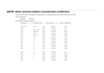
representing 1s22s22p1. For certain calculations, principal quantum numbers greater than 9 may be
required and for complex element ion, shell occupancies greater than 9 also may occur. To maintain
the three character shell notation, the integers beyond nine are represented alphabetically, that is 10 ≡
‘a’, 11 ≡ ‘b’ etc. Thus in Standard form, 2p6 6f11 11s1 is represented by ‘ 2p6 6fb bs1’. In Eissner
form, each orbital, starting from 1s is indexed. The index is an integer up to 9, but continues through
ADAS User manual
Chap9-08
17 March 2003
the upper case alphabet and then through the lower case alphabet. Thus 1s ≡ ‘1’, 2p ≡ ‘2’, 4f ≡ ‘A’. A
portion of the conversion table is
Orbital 1s
2s
2p
3s
3p
3d
4s
4p
4d
4f
Eissner 1
2
3
4
5
6
7
8
9
A
Orbital 5s
5p
5d
5f
5g
6s
6p
6d
6f
6g
Eissner B
C
D
E
F
G
H
I
J
K
The shell occupancy is represented as a two digit integer as 50+q and this precedes the shell index
character. Thus again the shell is represented by a three character field but is written with no
separation between the fields in the whole configuration. Thus in Eissner form 1s2 2s2 2p6 6g11 is
represented by ‘52152256361K’. ADAS works freely with both notations and subroutines in the
ADAS library transform from one to the other. Eissner form is the preferred form in ADAS series 7
codes since structure calculations there use the Autostructure code. Standard form is the preferred form
in ADAS series 8 codes since structure calculations there use the Cowan/O’Mullane code. Eissner
form is the most compact and is generally adopted with very complex configurations.
{$
$
+z
.
A promotional strategy Consider a group of ions
: z = z min ,..., z max } of the element
A set of configurations targetted on a structure calculation is established by promoting electrons from
the ground configurations of the ions. The criteria for promotion are shell-based and not set up ion by
ion - rather they are for the group of ions of the element. For complex ions, it is possible to have
ground configurations with more than one partially filled shell, which are called valence shells. By
reviewing the ground configurations of the ion group, a list of single valence shells present is identified
- likewise for double valence shells and in principal on to triple valence shells. The promotional
strategy depends on whether there is a single or double valence shell. At this time, ADAS808 has no
strategy for triple and higher valence shells.
1.
In the single valence shell case, we progress through each of the identified valence shell
orbitals in turn. Consider valence orbital nv l v . Distinguish promotions upward in
principal quantum number, that is to nl shells such that ∆n = n − nv > 0 from
promotions downward (in normal shell ordering) with ∆n < 0 . Principal quantum shell
promotions are determined by the permitted maximum ∆n and by the sign of the
promotion. The negative case allows promotions to empty inner shells to be treated. In
similar manner, promotions are ranked according to the maximum ∆l allowed with
2.
positive and negative ∆l handled separately. Note that the valence shells treated in this
manner are partially filled. Promotions from inner closed shells excluding the valence
shell, which may generate many less important configurations, are preferably restricted by
setting the lowest n-shell from which the promotion can occur and the highest n-shell to
which the promotion can take place. Again it is single electron promotion which is done.
Finally, it is a usual policy in accurate energy level calculations to include all the
configurations of a complex if one of the configurations of the complex is present. Such a
policy can generate large numbers of configurations in the complex ion case. It is helpful
to decide if whole complexes associated with the single electron promotion configurations
are to be included.
A similar procedure may be applied in the two valence shellcase but with the permissions
for each electron specified separately.
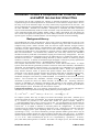
Configuration partitioning For complex ions, the number of configurations which satisfy even quite
restricted promotional rules can be large. Also, since these configurations often include more than one
unfilled shell, the level count for each configuration can be very large. Mechanisms beyond the basic
promotional rules are required to restrict the total level set to match available computer power. In
ADAS808, a second mechanism is introduced based on observational spectral regions of interest. The
principle is straightforward. Consider a spectral region of interest [ λ 0 , λ1 ] , which may be the range
of a particular spectrometer or an interval of special diagnostic value. For configurations I and J ,
( av )
introduce the configuration average energies E I
( av )
and E J
, the transition array average energy
∆E IJ( av ) = E J( av ) − E I( av ) and wavelength λ(IJav ) = hc / E J( av ) − E I( av )
ADAS User manual
Chap9-08
E J( av ) < E I( av )
. Configurations
17 March 2003
such that the transition wavelength
λ(IJav ) ∈ [ λ0 ,λ1 ] should be handled at high resolution, that is
level resolved, while configurations such that the transition wavelength λ IJ ∉ [ λ 0 , λ1 ] may be
handled at low resolution, that is configuration average. In general, there may be a set of wavelength
intervals of interest and from the total number of configurations, N C is partitioned into the level
( av )
resolved set, numbering N C , and the configuration average set, numbering N C , such that
R
A
N C = N C R + N C A . A further constraint may be imposed by setting a lower limit for transition
probabilities, thereby excluding very weak lines. At the configuration average level, this means a
lower limit
'min2( av )
on the reduced dipole matrix elements,
I
'J
2
for the transition arrays. A
preliminary stage of the Cowan structure code package generates configuration average energies and
reduced dipole matrix elements. This stage is rapid and makes low demands on computer resources. It
is convenient therefore to provide a transition array spectrum display so that the definition of
wavelength regions of interest can be done directly in interaction with the display. Immediate
information is returned to the user on resolved level counts and on resolved and unresolved
configuration counts, so that the size of the subsequent full structure computations may be assessed and
regulated. The transition array spectrum in which the ordinates are reduced dipole matrix elements
provides a relatively crude picture. Transition arrays between excited configurations are on the same
footing as those involving the ground configuration. There is no real population information. It is to
be noted however that the first stage of the Cowan code package also returns the reduced Born matrix
elements. Thus a configuration average population calculation and emissivity production is possible
without significant additional computational overhead. The configuration average transition array
emissivity coefficients for an ion provides a more realistic footing. On the other hand, at this first stage
of structure calculation, no basis for relative weighting of transition array emission functions from
different ionisation stages is available. Due to the sensitivity of the spectrum and dominant ionisation
stage to electron temperature, a constraint based on temperature is unsound at this point of the data
generation exercise. Equal weighting of ionisation stages abundances is the most appropriate choice.
ADAS808 presents either a reduced dipole or configuration average emissivity transition array
spectrum to the user. These details are described in detail below.
, is
Envelope features An envelope feature photon emissivity coefficient, denoted by
defined on a wavelength interval and is a composite feature arising from very many lines from a single
is suitable as a descriptor in wavelength intervals and at spectral
ionisation stage. The
resolutions where the individual component lines are unresolved or only partly resolved. This situation
occurs with very complex heavy element ions for which it becomes helpful and economical to handle
s). The primary use
the envelope feature rather than the individual line emissivity coefficients (
of ADAS808 is to set up calculations for very heavy species and so the wavelength intervals such as
[ λ 0 , λ1 ] above, introduced as a focus for partitioning configurations, are identified as the spectral
intervals over which the envelope features are sought. ADAS808 therefore provides drivers also for
calculations – see ADAS810 for more details.
the
)B3(&
)B3(&
3(&
)B3(&
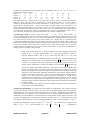
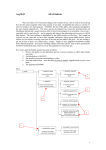
Program steps:
These are summarised in figure 9.08.
Figure 9.08
begin >
Input
element ion
range and
Te set
>
Read adf00
config. data
and evaluate
valence shells
Set promotional choices
and default
configurations
>
>
Compute
config. avge.
structure
parameters
ADAS User manual
<
end
Prepare
offline
drivers
<
Chap9-08
<
<
Output text
and driver
files
Display
level and config.
counts
<
Modify and
partition configs.
graphically
17 March 2003
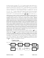
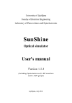
Interactive parameter comments:
The input window is as shown below
1.
2.
3.
Enter the element symbol. Note that the element symbol and nuclear charge
number boxes are linked so if one of them is changed, the other is
automatically updated. Also, set the minimum and maximum ion charges,
noting that the last ion of an element in this context is the hydrogen-like
stage with z = z 0 − 1 where z 0 is the nuclear charge.
Three sets of electron temperatures must be specified. These temperatures
are passed through to the final drivers and ultimately are the temperatures
used in the ADF04 , AD11 and ADF15 files. The Input temperatures are
usually the ADF standard reduced temperatures. Note that the temperature
set is editable and a user’s units of choice may be selected.
A pathway to ionisation potentials for all elements and their ions is required.
These data include the ground configurations and are provided in the Central
ADAS archive /packages/adas/adas/adf00/ .
3
1
2
4
4.
The Browse Comments button has no effect at this time. Clicking the Done
button moves you forward to the next window. Clicking the Cancel button
takes you back to the previous window.
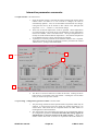
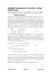
The processing – configuration generator window is shown below:
1.
2.
ADAS User manual
The processing window has three separate modes of operation which may be
selected. In Configuration Generator mode, the window appearance is as
shown below. This mode must be completed before the other modes are
meaningful and is described below.
The sub-window on the left permits the setting up of a promotional strategy
for configuration generation. You must note that this strategy applies to
simultaneously to all ions selected on the Input window. Single and
double valence shell cases are chosen as required and the fields which are
Chap9-08
17 March 2003
3.
4.
5.
6.
presented depends on that selection. The one valence shell case is illustrated
below.
The valence shells are listed. Clicking on a member of the list causes it to
appear in the selection widget. Then the choices made on the left at 4 apply
to that valence electron.
Make the preferred choices, then click on the Set Default Configurations
Button. Done is appended to the chosen valence shell in the list widget.
Work through each shell in the list. Note that a shell may be reworked
simply by reselecting it.
In like manner select the Two open shell button and then work through the
two valence shell list.
When the promotional strategy is complete, enter an ion charge from the
selected range in the text box . The set of default configurations for that ion
is presented in the table together with the number of levels, which would
result from that configuration. The table is editable to add further
configurations which are not entered by the promotional strategy.
9
1
5
2
3
4
6
10
7
8
7.
8.
The total level count for the ion is shown.
It is now possible to select configurations to be treated as resolved by
activating the right-most buttons. The number of levels in the resolved set
of configurations is displayed in the lower box .
9. There are two sets of Select All and Deselect All buttons which apply to the
right-most button selectors. The upper pair apply to the lists for every ion in
the whole ion range simultaneously. The lower pair apply only to the
currently displayed ion.
10. Additional strategies for inner shell promotion are in development and are
subject to change.
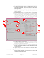
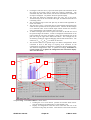
The processing - configuration selection window is shown below
1. Clicking the Configuration Selection button presents the window shown
below, in which the sub-window on the left is now used to show a a stick
spectrum of the various transition arrays.
ADAS User manual
Chap9-08
17 March 2003
2.
3.
4.
5.
6.
Clicking the Calculate Survey Spectrum button spawns the calculation of the
first stage of the Cowan code to obtain the necessary parameters. The
calculation may take a few minutes, but then all information is available the
stick plot is displayed. Any further selections operate rapidly.
The stick plot shows the transition arrays for every ion in the group.
Transition arrays for the ion selected at the right are marked with sticks in a
contrasting colour.
The wavelength range of the stick plot may be altered and logarithmic or
linear axes chosen.
The plot area is active. The mouse may be used to delimit rectangular areas
which are the spectral intervals of special interest. The base of the rectangle
set a minimum value of the reduced dipole matrix element for transition
array configurations to be included in the resolved set.
To mark a rectangle, first activate a square row button on the left of a row of
the spectral ranges sub-window, so that it is displayed and the button on the
right to make the row active for editing. Drag out a horizontal line on the
plot area using the right mouse button and release. The rectangle may be
stretched by catching an edge and dragging with the left mouse button. The
'
7.
selections, ( λ min , λ max , min ) are shown in the boxes.
The left hand button of a spectral range row defines configurations which
contribute to lines in that range as requiring level resolution on the
configuration list and that configuration is marked its button indicator light.
The selected configurations count is updated accordingly. Remember to
reselect an ion at 3. to update the configuration list sub-window display
after each alteration.
2
5
1
3
7
2
6
4
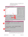
The processing – level count window is shown below
1. Clicking the Level Count button presents the window shown below.
The sub-window to the left displays a count summary plot.
2. Display of configuration counts and level counts for each ion in the
selected ion range may be chosen. Note that the Total Levels and Total
ADAS User manual
Chap9-08
17 March 2003
3.
4.
Configurations may be shown prior to the calculating the survey
spectrum. Selected Levels and Selected Configurations require the
survey spectrum to be calculated first.
The graph display scales may be adjusted.
Note the summary information
1
3
2
4
The output options window is as shown below
1
2
1.
ADAS User manual
The Text Output button activates writing to a text output file. The file name
may be entered in the editable File name box when Text Output is on. The
default file name ‘paper.txt’ may be set by pressing the button Default file
Chap9-08
17 March 2003
2.
name. A ‘pop-up’ window issues a warning if the file already exists and the
Replace button has not been activated.
The primary output is to an adf34 sub-directory which can be entered and/or
selected.
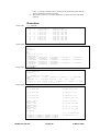
Illustration:
Table 9.08a
w_7_adf34.dat
2
Table 9.08b
-5
74
74
74
74
74
74
74
74
74
-1
2
8
8
8
8
8
8
8
8
8
10
w
w
w
w
w
w
w
w
w
1.0
5.d-09
4f13 5s2 0
4f13 5s2 3
4f12 5s2 7
4f13 5s2
4f12 5s2
4f13 5s2
4f13 5s2
4f12 5s2
4f12 5s2
0130
1.0 0.65
5p6
5p5 6p1
5p6 6p1
5p5 6s1
5p6 6s1
5p5 5d1
5p5 6d1
5p6 5d1
5p6 6d1
0.0
0.5
w_7_inst.dat
z0 74
zi 7
parity-1 3
parity-2 6
E2 3
M1 3
scale 93 99 93 93 93
temperature 25
2.00000E+02
5.00000E+02
1.00000E+04
2.00000E+04
1.00000E+05
2.00000E+05
2.20000E+06
2.20000E+06
2.20000E+06
2.20000E+06
2.20000E+06
2.20000E+06
2.20000E+06
Table 9.08c
5.d-11-2
4f13 5s2
4f13 5s2
4f12 5s2
4f13 5s2
4f12 5s2
4f13 5s2
4f13 5s2
4f12 5s2
4f12 5s2
1.00000E+03
5.00000E+04
5.00000E+05
2.20000E+06
2.20000E+06
2.20000E+06
2.00000E+03
5.00000E+03
1.00000E+06
2.00000E+06
2.20000E+06
2.20000E+06
w_7_pp.dat
1
Allan Whiteford
15/12/79
1
C
Comments are for losers!
&FILES ifgfile = './ifg#w_7_adf34.dat' , outfile = './w_7_adf04.dat'
&END
&OPTIONS ip =
1134988.8, coupling = 'IC' , aval = 'YES' ,
isonuclear = 'NO', lweight = 'NO' , comments = 2, numtemp = 14, &END
1 2 3 4 5 6 7 8 9 10 11 12 13 14
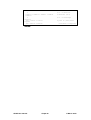
Table 9.08d
w_7_pec_drv.dat
w + 9
74
10
1475969.1
./w_9_adf04.dat
# input adf04 file
./w_9_adf11.dat
# output plt file
./w_9_adf15.dat
# output pec file
./w_9_adf40.dat
# output f_pec file
lmetr = false
metastables
ltscl = true
temperatures
ldscl = false
densiities
lbrdi = true
broadening
# true to resolve
# true for z-scaled
# true for z-scaled
# true for ion temp.
13
2.000E+02 5.000E+02 1.000E+03 2.000E+03
5.000E+03 1.000E+04 2.000E+04 5.000E+04
1.000E+05 2.000E+05 5.000E+05 1.000E+06
ADAS User manual
Chap9-08
# no. of temperatures
# temperatures (K)
17 March 2003
2.000E+06
5
1.000E+11 1.000E+12 1.000E+13 1.000E+14
1.000E+15
2
intervals
128 2.759e+01 2.112e+03
triplets
128 5.890e-01 2.242e+00
# no. of densities
# densities (cm-3)
# no. of wavelength
# pixel no.,wvmin,wvmax
(wavelenths in Angstrom)
Notes:
ADAS User manual
Chap9-08
17 March 2003