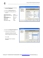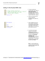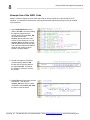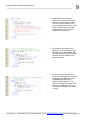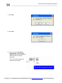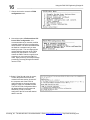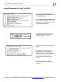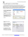
1
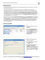
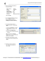
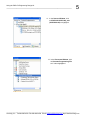
Series PMC-CX
Virtex-2 Based FPGA
PMC Module
Using the PMC-CX Engineering Design Kit
ACROMAG INCORPORATED
30765 South Wixom Road
P.O. BOX 437
Wixom, MI 48393-7037 U.S.A.
Copyright 2007, Acromag, Inc., Printed in the USA.
Data and specifications are subject to change without notice.
Tel: (248) 295-0310
Fax: (248) 624-9234
8500-807-C10G009
2
TABLE OF
CONTENTS
OBJECTIVE
Using the PMC-CX Engineering Design Kit
___________________________________________________________________
Getting Started ………………………………………….…….
3
Configuring Xilinx …………………………………………….
3
Adding to the Provided VHDL Code ………………..…….
7
Example Use of the VHDL Code ..............................…….
8
Create a Program Hex File ………………………………….
12
Loading the .mcs File Into the CX Board ……………
15
Using the Example C to Run The FPGA .…….…….…….
17
Creating a MFC Program to use with the CX Board ……
18
Example MFC Code.....……......……......……......…...……..
26
The purpose of this document is to provide basic instructions on using the “PMC-CX
Engineering Design Kit” with the PMC-CX Boards. It will focus on programming the
FPGA of the PMC-CX1002 using VHDL, but can be easily modified to use with any
model of the CX line. This document also shows how to use the supplied dll files with
a MFC application. It is assumed that the user has a working knowledge of Xilinx,
VHDL and Visual C++.
All trademarks are the property of their respective owners.
______________________________________________________________________________________
Acromag, Inc. Tel:248-295-0310 Fax:248-624-9234 Email:[email protected] http://www.acromag.com
Using the PMC-CX Engineering Design Kit
__________________________________________________________________
3
Getting Started
When using the any CX board besides the CX1002 simply substitute its model number for the “CX1002”
through out this document.
Turn off your computer, and unplug the power cord. Before touching either board, make sure to
discharge all static electricity. Then attach the CX1002 to the APC-PMC board. Insert the APC-PMC
into an empty PCI Bus in your computer. When restarting your computer, you will be prompted to insert
a CD with the drivers on it. At this point, insert the CD PCI Win32 Driver Software into your CD-ROM
drive. When the plug and play installation has completed, follow the steps to install the PCISW-API-WIN
software on your computer. When finished, insert the CD titled PMC-CX Engineering Design Kit and
copy the CX1002 folder to your computer.
Before you start, read through the Readme_CX1002.txt file found in the CX1002 Folder of the PMC-CX
Engineering Design Kit. Also, familiarize yourself with the PMC-CX1002 User’s Manual and the PCICX
Function Reference included on the PCI Win32 Driver Software CD. The user’s manual gives the
memory addresses of all the registers, and their purposes. The function reference gives information on
how to use the DLL file in C/C++, Visual Basic, and LabView (we will be focusing only on using the
C/C++ demo program).
Configuring Xilinx
1. Make a new directory and call it
xc2v1000.
2. From the CX1002\VHD Files\
folder, copy the all the vhdl files in
into the xc2v1000 folder. Then
from the CX1002 folder copy the
CONSTRAINTS.ucf file to the
xc2v1000 folder.
3. Start Xilinx’s Project Navigator
from your start menu.
4. Open a new project by selecting
File Æ New Project.
5. In the Project Name field, type
xc2v1000. In the Project
Location field type the path name
where to find the xc2v1000 folder.
Make sure the Top-Level Module
Type field is HDL, and click Next.
______________________________________________________________________________________
Acromag, Inc. Tel:248-295-0310 Fax:248-624-9234 Email:[email protected] http://www.acromag.com
4
Using the PMC-CX Engineering Design Kit
___________________________________________________________________
6. Enter the following information if
using the CX1002:
Device Family:
Device:
Package:
Speed Grade:
Top-Level Module:
Synthesis Tool:
Simulator:
Virtex2
xc2v1000
fg456
-4
HDL
XST
Modelsim-XE VHDL
Then click Next.
7. In the Create New Source dialogue
box, click Next to go on the
following screen (we will not be
creating a new source at this time).
8. We will next add the files we
copied from the CD. Follow these
steps:
A. Press the Add Source… Button
B. Press Ctrl-A to select all of the
files.
C. Press on the Open Button.
D. Every .ucf and .vhd files should be
included.
Make sure that every Copy to
Project check boxes are deselected,
and then click on Next.
9. Review the specifications to make
sure they are correct, and then click
Finish.
10. Make sure that all of the files
were added successfully and
click on OK.
______________________________________________________________________________________
Acromag, Inc. Tel:248-295-0310 Fax:248-624-9234 Email:[email protected] http://www.acromag.com
Using the PMC-CX Engineering Design Kit
__________________________________________________________________
5
11. In the Sources Window, click
on XC2V1002-XC2V1002_arch
(XC2V1002.vhd) to highlight it.
12. In the Processes Window, click
on Generate Programming File
so it is also highlighted.
______________________________________________________________________________________
Acromag, Inc. Tel:248-295-0310 Fax:248-624-9234 Email:[email protected] http://www.acromag.com
6
Using the PMC-CX Engineering Design Kit
___________________________________________________________________
13. Click on Process from the menu bar,
and click on Properties.
14. Click on the Startup Options tab.
15. Verify that the following options are
selected:
FPGA Start-Up Clock:
Enable Internal Done Pipe:
Done:
Enable Outputs:
Release Write Enable:
Release DLL:
Match Cycle:
Drive Done Pin High:
CCLK
Not Checked
6
(Default) 5
5
Default
Auto
Check
16. Click on the Configuration Options tab.
17. Change only the following option:
Configuration Pin M0: Pull Down
All other settings should stay the same
Click on OK.
Xilinx should now be completely
configured.
______________________________________________________________________________________
Acromag, Inc. Tel:248-295-0310 Fax:248-624-9234 Email:[email protected] http://www.acromag.com
Using the PMC-CX Engineering Design Kit
__________________________________________________________________
7
Adding To The Provided VHDL Code
1. To revise or add to the
provided VHDL code, begin by
double clicking on the
XC2V1002-XC2V1002_arch
(XC2V1002.vhd) file located in
the Sources window. This will
open the VHDL file for editing.
2. Under the commented code
(line 261) additional
components and signals may
be added.
3. After the begin keyword (line
403) additional instantiations
for components may be added.
In this guide, we will only be
adding signals. No components
will be added at this time.
4. For simplicity we suggest
adding to or revising the
provided VHDL code that is
associated with the I/O. To use
the rear I/O, begin by double
clicking on the XC2V1002XC2V1002_arch
(XC2V1002.vhd) file located in
the Sources window if it is not
already opened. This will open
the VHDL file associated with
the rear I/O for editing.
Note: It is good programming
practice to group like segments
together to avoid confusion later
when editing code.
______________________________________________________________________________________
Acromag, Inc. Tel:248-295-0310 Fax:248-624-9234 Email:[email protected] http://www.acromag.com
8
Using the PMC-CX Engineering Design Kit
___________________________________________________________________
Example Use of the VHDL Code
Below is a simple example of some VHDL that could be used to control five of the CX1002’s LVTTL
channels. It is included to show how the code supplied with the Engineering Design Kit can be modified
for personal use.
1. Open XC2V1002.vhd and scroll
down to line 256. We will be adding
the signals (registers that the
counter will be using. Counter_EN
will enable the counter,
Counter_Inc will determine if the
counter is incrementing or not, and
Counter_Reg is the binary counter.
Add the lines in the box on the right.
This code will create a new address
strobe for the counter. It will be
located in register 0x8020.
Note: Only add the code within the
box. The lines above and below are
included as a reference.
2. We will now replace a previously
unused memory address. Add
the two lines of code as shown to
the right at line 573. This will be
the location in memory to access
the counter.
3. At line 730 we will insert the counter’s
write strobe. This will pulse
Counter_Stb when there is a write
command to the Counter_Adr. Add
the lines of code as shown.
______________________________________________________________________________________
Acromag, Inc. Tel:248-295-0310 Fax:248-624-9234 Email:[email protected] http://www.acromag.com
Using the PMC-CX Engineering Design Kit
__________________________________________________________________
9
4. At line 871 there is the process
statement to control the Differential
Direction Control Register. Add the
red code to cause channels 0-3 to
become outputs when there is a write
to the counter address, and make
sure that channel 4 is an input to
handle the increment line.
5. The enable for the counter will be
handled in the process statement at
line 930. Notice that Counter_EN
receives its information from the local
data bus (LD) bit-5. Add the code
shown on the left.
6. The external increment line for the
counter will be handled in the process
statement at line 945. Notice that
the Counter_Inc receives its
information from channel 4. The
counter is stopped and started using
this input line. Add the code to the
left directly following the code added
in step 5.
______________________________________________________________________________________
Acromag, Inc. Tel:248-295-0310 Fax:248-624-9234 Email:[email protected] http://www.acromag.com
10
Using the PMC-CX Engineering Design Kit
___________________________________________________________________
7. The counter will be handled in this
process statement. When the counter
is enabled, it will check the
Counter_Inc line to see if it has a
positive logic equivalence of ‘1’ every
positive clock edge. If it does then the
counter will be incremented. Add this
code beginning at line 960.
8. Add the following lines of red code to
the READ_DATA MUX lines beginning
about line 1018. This will allow the
read and write commands to access
the counter address at 8020H.
Bits 3-0 will hold the four bits of the
counter, bit 4 will hold the increment
line, and bit 5 will hold the enable.
______________________________________________________________________________________
Acromag, Inc. Tel:248-295-0310 Fax:248-624-9234 Email:[email protected] http://www.acromag.com
Using the PMC-CX Engineering Design Kit
__________________________________________________________________
11
Create A Program Hex File
1. Select XC2V1002-XC2V1002_arch
(XC2V1002.vhd) in the Sources Window.
2. Select Generate PROM, ACE, or JTAG File
in the Processes Window.
3. Right-click on Generate PROM, ACE, JTAG
File, and click on Rerun all.
Note: If there are any errors, correct them and
repeat steps 2 and 3.
4. A black prompt screen may appear for a few
seconds after step 3. Ignore this screen and
DO NOT type inside it.
5. Select Prepare a PROM File and
click Next
______________________________________________________________________________________
Acromag, Inc. Tel:248-295-0310 Fax:248-624-9234 Email:[email protected] http://www.acromag.com
12
Using the PMC-CX Engineering Design Kit
___________________________________________________________________
6. Enter the following information:
Select:
PROM File Format:
Memory Fill Value:
PROM File Name:
Location:
Generic Parallel PROM
MCS
FF
CX1002
Path to the CX1002 file
Click on Next.
7. Enter the following information for the
LX40:
Auto Select PROM:
Parallel PROM Density:
Number of Data Streams:
Loading Direction:
Unchecked
4M
1
UP
Click Add and the click Next.
______________________________________________________________________________________
Acromag, Inc. Tel:248-295-0310 Fax:248-624-9234 Email:[email protected] http://www.acromag.com
Using the PMC-CX Engineering Design Kit
__________________________________________________________________
13
8. Click Finish on the following page.
9. Click on OK to add a device.
10. Select xc2v1002.bit and click Open.
______________________________________________________________________________________
Acromag, Inc. Tel:248-295-0310 Fax:248-624-9234 Email:[email protected] http://www.acromag.com
14
Using the PMC-CX Engineering Design Kit
___________________________________________________________________
11. Select No.
12. Select OK.
14. From the menu go Operations
->Generate File. A message will
appear on the screen to indicate the
PROM file was successfully
generated.
The .mcs file is now ready to be
loaded into the CX1002.
______________________________________________________________________________________
Acromag, Inc. Tel:248-295-0310 Fax:248-624-9234 Email:[email protected] http://www.acromag.com
Using the PMC-CX Engineering Design Kit
__________________________________________________________________
15
Loading the mcs File Into the CX Board
1. Load PCICXDemo.exe found in
PCISW_API_WIN\c_example\PCILX\
msdev6\Release\ created by the PCI
Win32 Driver Software CD-ROM.
Note: The PCISW_API_WIN folder
will be installed by default at
C:\Program Files\Acromag\ .
2. Begin by entering 1 and reading the
operating instructions.
3. Press 2 to select which type of LX
board to use.
4. Type in the menu number that
corresponds with your board model
and press Enter.
5. Answer Y to the first example if the
FPGA is configured with the Acromag
example design or the FPGA is
configured with a design whose basic
structure is the Acromag example
design. Otherwise type N and press
Enter.
6. Type Y if there is a mezzanine module
attached (like the AXM-EDK that we
are using).
______________________________________________________________________________________
Acromag, Inc. Tel:248-295-0310 Fax:248-624-9234 Email:[email protected] http://www.acromag.com
16
Using the PMC-CX Engineering Design Kit
___________________________________________________________________
7. Choose choice 4 to access the FPGA
configuration menu.
8. Next select option 2: Perform direct PCI
bus to Xilinx configuration. It is
recommended that you test this modified
example design using the reconfiguration
direct method. It is not recommended that
the flash be overwritten until you have
tested your code. The reconfigure direct
method will allow program of the FPGA
directly from the PCI bus. If for some
reason the PMC CX does not perform as
expected, you can power the PMC CX
down. Upon power-up, the example design
provided by Acromag will again be loaded
into the FPGA.
9. Select Y if the file path given is correct,
or enter the path to the mcs file we
created in the last section. Answer Y if
the computer asks if the FPGA is
configured with an Acromag example
design or if this is a mezzanine model.
The PCICX FPGA Configuration Menu
will appear after a few moments and
should say “FPGA is currently
configured if the CX board was loaded
with the new file.
______________________________________________________________________________________
Acromag, Inc. Tel:248-295-0310 Fax:248-624-9234 Email:[email protected] http://www.acromag.com
Using the PMC-CX Engineering Design Kit
__________________________________________________________________
17
Using the Example C to Run The FPGA
1. From the PCIAX FPGA Configuration
Menu, type 99 and press Enter to return to
the PCILX Main Menu.
2. Open the Raw memory access menu by
typing 7 and pressing Enter. This menu
will allow us to use the built in functions to
read and write to the board.
3. Select 2 and press Enter to access the
PCIBAR2 memory space where the
AXM_D registers are located.
4. To write to the board, Type 3 and press
Enter.
5. Type 8020, the hexadecimal memory
address of Counter_Adr, and press
Enter. Then enter the data to enable
the counter in hex, remembering that bit
5 enables the counter, bit 4 is the
increment line, and bits 3-0 are the
counter.
6. This concludes the setup, and the
counter should function as previously
described.
______________________________________________________________________________________
Acromag, Inc. Tel:248-295-0310 Fax:248-624-9234 Email:[email protected] http://www.acromag.com
18
Using the PMC-CX Engineering Design Kit
___________________________________________________________________
Creating a MFC program to use with the CX Board
For this section a general understanding of C/C++ and the Visual Studios software is required. Even
though a step by step process is given, much of the syntax may be confusing if one is not familiar to
programming in Visual C++. Primarily the following sections shows how to enable use of the dll functions, while
creating a simple MFC program. References to PCICX Function Reference and PCI Win32 Driver User’s
Manual are made throughout this section. A copy of each should be close for reference as we create the MFC
executable. These files are found in PCISW_API_WIN\doc created by the PCI Win32 Driver Software CDROM. Note: The PCISW_API_WIN folder will be installed by default at C:\Program Files\Acromag\ .
1. Open Microsoft Visual Studio 2008 from
the start menu. Some screens may
vary if using a different version of
Visual Studios.
2. Open a new MFC project by clicking on
File Æ New and selecting Project.
3. Expand the C++ tab and click MFC.
Under Visual Studio installed templates
click MFC Application. Enter the
project name CX and leave the “create
directory for solution” box checked.
Click OK.
4. The MFC Application Wizard
appears.
Click Next. On the Application Type
screen choose the Dialog Based
option. Deselect the Use Unicode
Libraries option. Click Next until the
Generated Classes window appears;
for Generated Classes, select
CCXDlg. Then click Finish.
5. Open PCI Win32 Driver Software
User’s Manual to page 16. Here it
gives instructions on using the dll in
Microsoft Visual C++ 6. Follow along
as we visually go through this process.
______________________________________________________________________________________
Acromag, Inc. Tel:248-295-0310 Fax:248-624-9234 Email:[email protected] http://www.acromag.com
Using the PMC-CX Engineering Design Kit
__________________________________________________________________
19
6. Select Project form the menu bar
and click CX Properties.
7. Under Configuration Properties
expand the C/C++ tab and highlight
the General sub-menu. Select All
Configurations for Configuration.
In the Additional include
directories edit box type in the path
to the c header files. If the PCI
Win32 Driver Software was installed
in the default location then they will
be found at “C:\Program Files\
Acromag\PCISW_API_WIN\
c_include”.
8. Next expand the Linker tab and
highlight the General sub-menu.
In the Additional library
Dependencies edit box type in
the location of the above library. If
the PCI Win32 Driver Software
was installed in the default
location then they will be found at
“C:\Program Files\ Acromag\
PCISW_API_WIN\c_lib”.
9. Highlight the Input sub-menu.
Under Additional Dependencies
type PCICX.lib.
Click Apply
Click OK
______________________________________________________________________________________
Acromag, Inc. Tel:248-295-0310 Fax:248-624-9234 Email:[email protected] http://www.acromag.com
20
Using the PMC-CX Engineering Design Kit
___________________________________________________________________
10. Locate the Solution
Explorer Window on the
bottom tabs of the screen
or View Æ Solution
Explorer from the main
menu.
Expand the Source Files
tab and double click
CXDlg.cpp to open and
edit the file.
11. Add the following three lines of code
directly beneath the existing
“#include…” statements to produce
the resulting code on the right :
#include <windows.h>
#include "PCICX.h"
#include "PCIErrorCodes.h"
12. All the dll functions should now be
enabled. To check, click on the
at the top
Debug Program button
of the screen. Choose “Yes” if a
prompt appears asking if the user
would like to build files.
Note: Be sure to copy PCICX.h, PCIErrorCodes.h,
and PCICX.lib into your project folder in order to
execute the program. You can find these files at
C:\ProgramFiles\Acromag\PCISW_API_WIN\c_includ
e and
C:\ProgramFiles\Acromag\PCISW_API_WIN\c_lib
respectively.
______________________________________________________________________________________
Acromag, Inc. Tel:248-295-0310 Fax:248-624-9234 Email:[email protected] http://www.acromag.com
Using the PMC-CX Engineering Design Kit
__________________________________________________________________
21
13. The example dialog program should
load as shown to the left. If not, then
the dll has not been configured
correctly. Repeat steps 7 – 12 and
make sure all the paths and file
names are correct.
Exit the dialog box by clicking OK.
NOTE : If you have not made any
changes to the generated code other
than step 11 but receive an error
stating “error spawning cmd.exe” do
the following :
Go to Tools Æ Options
Expand the Project and Solutions tab
Click on VC++ Directories
Add the following lines
$(SystemRoot)\System32
$(SystemRoot)
$(SystemRoot)\System32\wbem
14. In the Workspace window click on
the ResourceView tab, expand the
CX.rc and Dialog folders, and then
double click on IDD_CX_DIALOG for
editing. The dialogue editor side
panel should also appear. If not,
locate it from View Æ Toolbars Æ
Dialog Editor.
15. Delete both the cancel button and
the TODO static text in the example
dialog program above. Then add the
components listed on the following
page and move the OK button.
Make sure the Properties side panel
is open while editing. (right click on
any object and click Properties to
open).
When finished, the dialog box should
look like the figure to the left.
______________________________________________________________________________________
Acromag, Inc. Tel:248-295-0310 Fax:248-624-9234 Email:[email protected] http://www.acromag.com
22
Using the PMC-CX Engineering Design Kit
___________________________________________________________________
Object
Static Text
Control ID (under Misc.
tab)
IDC_STATIC
Static Text
Static Text
IDC_MULTBRDSTATIC
IDC_ISFPGACONFIG
Static Text
Static Text
Static Text
Static Text
Static Text
Edit Control
IDC_PATHSTATIC
IDC_OPSTATIC
IDC_ADRMODESTATIC
IDC_ADRSTATIC
IDC_WRITESTATIC
IDC_CRDNUM
Caption (under
Appearance tab)
Choose what board type to
open:
Select Card Number:
The FPGA is already
configured.\nTo reconfigure
enter in the information
below:
Path of the .mcs file:
Choose an operation type:
Change transfer size:
Address Offset:
Data to write:
--
Edit Control
IDC_FILENAME
--
Edit Control
IDC_ADROFF
--
Edit Control
Button
Button
Button
Combo Box
IDC_TOWRITE
IDC_OPENCARD
IDC_PROG
IDC_RORWBUTTON
IDC_BRDTYPE
-Open Card
Program
Read
--
Combo Box
IDC_RORW
--
Combo Box
IDC_ADRMODE
--
Location
----
-----Next to “select card
number” text
Next to “path of the .mcs
file” text
Next to “Address offset”
text
Next to “Data to Write” text
---Next to “Choose what
board type to open” text
Underneath “Choose an
operation type” text
Next to “Change transfer
size” text
Note: Remember when creating the combo boxes, make sure to click and drag the
area for the control as if the drop down menu is open. This is done by selecting the
down arrow on the combo box.
16. For each combo box right-click we
need to enter the data shown in the
table. Highlight Data under the
Behavior tab of the Properties
menu. Enter the information shown,
using a semicolon to separate items.
17. Also, in the Behavior tab set the
option Sort Æ False. Likewise, set
Type Æ Droplist.
Combo Box ID
IDC_BRDTYPE
IDC_RORW
IDC_ADRMODE
Data
CX1002R
CX2002R
CX1003R
CX2003R
Read
Write
Byte
Word
DWord
______________________________________________________________________________________
Acromag, Inc. Tel:248-295-0310 Fax:248-624-9234 Email:[email protected] http://www.acromag.com
Using the PMC-CX Engineering Design Kit
__________________________________________________________________
Control ID
IDC_BRDTYPE
IDC_CRDNUM
IDC_FILENAME
IDC_MULTBRDSTATIC
IDC_OPENCARD
IDC_PATHSTATIC
IDC_PROG
IDC_STATIC
Visible
True
True
True
True
True
True
True
True
Disabled
False
True
True
True
True
True
True
False
23
18. Set the following properties. Select a
control and expand the Behavior tab
of the properties menu to edit these
options. All other controls not in this
table should have their visibility set to
False.
19. Click on the Debug Program
at the top of the screen.
button
The dialog screen should now look
like this.
20. Click OK to close the program.
21. In the Workspace window click the Class
View tab, and expand
CX classes. Right-click on CCXDlg and
click Add Æ Add Variable. Enter the
following information:
Option
Variable Type
Variable Name
Access
Value
Short
m_Handle
protected
Click Finish.
______________________________________________________________________________________
Acromag, Inc. Tel:248-295-0310 Fax:248-624-9234 Email:[email protected] http://www.acromag.com
24
Using the PMC-CX Engineering Design Kit
___________________________________________________________________
22. Right-click on the CCXDlg and click Add Æ
Add Function to open the “Add Member
Function Wizard”. Enter the following
information and also select the Static option.
Note: In the “Return Type” and “Parameter
Type” fields you are able to type in the desired
value if it is not contained in the drop down
menu.
Return Type : CString
Function Name: GetStatus
Parameter type: short
Parameter name: nStatus (then click Add)
Access : protected
Static : box is checked
Click Finish.
23. In the Workspace window click on the
ResourceView tab, expand the CX.rc and
Dialog folders, and then double click on
IDD_CX_DIALOG. Member variables now
need to be attached to the controls. Right
click on the control to be edited and click Add
Variable to open the Add Member Variable
Wizard.
First click on the Category dropdown and
choose “Value”. The following options in the
table then become available. Enter the values
and then press Finish.
Control IDs
IDC_ADRMODE
IDC_ADROFF
IDC_BRDTYPE
IDC_CRDNUM
IDC_FILENAME
IDC_RORW
IDC_TOWRITE
Variable Name:
m_AdrMode
m_AdrOffset
m_BoardType
m_CardNum
m_FileName
m_ReadOrWrite
m_WData
Type
Int
CString
Int
Int
CString
Int
DWORD
______________________________________________________________________________________
Acromag, Inc. Tel:248-295-0310 Fax:248-624-9234 Email:[email protected] http://www.acromag.com
Using the PMC-CX Engineering Design Kit
__________________________________________________________________
25
24. Right click on the following controls
and select Add Event Handler to
assign the following messages. A
default Function handler name is
generated and does NOT need to
be changed. Click the Add and
Edit button to save changes and
exit the Event Handler Wizard.
Object IDs
IDC_BRDTYPE
IDC_OPENCARD
IDC_PROG
IDC_RORW
IDC_RORWBUTTON
IDOK
Message Type
CBN_SELCHANGE
BN_CLICKED
BN_CLICKED
CBN_SELCHANGE
BN_CLICKED
BN_CLICKED
25. The Class View tab should now
look like something this. Doubleclick any function declaration to
edit that function.
26. Use the code provided on pages
26 to 37 for the member functions.
All colored code is new code which
you must add to the code
generated by the MFC Wizards.
Make sure your code matches the
code provided.
27. From the menu bar at the top of
the screen, click on Build Æ Clean
CX. Then click on Build CX. If
there are no errors, click on the
at the
Debug Program button
top of the screen again. The
program should now allow the user
to open a board, execute a flash
configuration, and read and write to
a specified memory location.
______________________________________________________________________________________
Acromag, Inc. Tel:248-295-0310 Fax:248-624-9234 Email:[email protected] http://www.acromag.com
26
Using the PMC-CX Engineering Design Kit
___________________________________________________________________
Example MFC Code
Note that the following code is color coded. Black indicates what was added by the ClassWizard, and the colored
code is specific to our example. The code segments colored green are comments to help explain the purpose of
each section.
// CXDlg.cpp : implementation file
//
#include
#include
#include
#include
#include
#include
"stdafx.h"
"CX.h"
"CXDlg.h"
<windows.h>
"PCICX.h"
"PCIErrorCodes.h"
#ifdef _DEBUG
#define new DEBUG_NEW
#endif
// CAboutDlg dialog used for App About
class CAboutDlg : public CDialog
{
public:
CAboutDlg();
// Dialog Data
enum { IDD = IDD_ABOUTBOX };
protected:
virtual void DoDataExchange(CDataExchange* pDX);
// DDX/DDV support
// Implementation
protected:
DECLARE_MESSAGE_MAP()
};
CAboutDlg::CAboutDlg() : CDialog(CAboutDlg::IDD)
{
}
void CAboutDlg::DoDataExchange(CDataExchange* pDX)
{
CDialog::DoDataExchange(pDX);
}
BEGIN_MESSAGE_MAP(CAboutDlg, CDialog)
END_MESSAGE_MAP()
// CCXDlg dialog
CCXDlg::CCXDlg(CWnd* pParent /*=NULL*/)
: CDialog(CCXDlg::IDD, pParent)
, m_Handle(0)
______________________________________________________________________________________
Acromag, Inc. Tel:248-295-0310 Fax:248-624-9234 Email:[email protected] http://www.acromag.com
Using the PMC-CX Engineering Design Kit
__________________________________________________________________
,
,
,
,
,
,
,
27
m_BoardType(0)
m_AdrMode(0)
m_AdrOffset(_T(""))
m_CardNum(0)
m_FileName(_T(""))
m_ReadOrWrite(0)
m_WData(0)
{
m_hIcon = AfxGetApp()->LoadIcon(IDR_MAINFRAME);
}
void CCXDlg::DoDataExchange(CDataExchange* pDX)
{
CDialog::DoDataExchange(pDX);
DDX_CBIndex(pDX, IDC_BRDTYPE, m_BoardType);
DDX_CBIndex(pDX, IDC_ADRMODE, m_AdrMode);
DDX_Text(pDX, IDC_ADROFF, m_AdrOffset);
DDX_Text(pDX, IDC_CRDNUM, m_CardNum);
DDX_Text(pDX, IDC_FILENAME, m_FileName);
DDX_CBIndex(pDX, IDC_RORW, m_ReadOrWrite);
DDX_Text(pDX, IDC_TOWRITE, m_WData);
}
BEGIN_MESSAGE_MAP(CCXDlg, CDialog)
ON_WM_SYSCOMMAND()
ON_WM_PAINT()
ON_WM_QUERYDRAGICON()
//}}AFX_MSG_MAP
ON_CBN_SELCHANGE(IDC_BRDTYPE,
&CCXDlg::OnCbnSelchangeBrdtype)
ON_BN_CLICKED(IDC_OPENCARD, &CCXDlg::OnBnClickedOpencard)
ON_BN_CLICKED(IDC_PROG, &CCXDlg::OnBnClickedProg)
ON_CBN_SELCHANGE(IDC_RORW, &CCXDlg::OnCbnSelchangeRorw)
ON_BN_CLICKED(IDC_RORWBUTTON,
&CCXDlg::OnBnClickedRorwbutton)
ON_BN_CLICKED(IDOK, &CCXDlg::OnBnClickedOk)
END_MESSAGE_MAP()
// CCXDlg message handlers
BOOL CCXDlg::OnInitDialog()
{
CDialog::OnInitDialog();
// Add "About..." menu item to system menu.
// IDM_ABOUTBOX must be in the system command range.
ASSERT((IDM_ABOUTBOX & 0xFFF0) == IDM_ABOUTBOX);
ASSERT(IDM_ABOUTBOX < 0xF000);
CMenu* pSysMenu = GetSystemMenu(FALSE);
if (pSysMenu != NULL)
{
CString strAboutMenu;
strAboutMenu.LoadString(IDS_ABOUTBOX);
if (!strAboutMenu.IsEmpty())
{
pSysMenu->AppendMenu(MF_SEPARATOR);
pSysMenu->AppendMenu(MF_STRING, IDM_ABOUTBOX,
strAboutMenu);
}
______________________________________________________________________________________
Acromag, Inc. Tel:248-295-0310 Fax:248-624-9234 Email:[email protected] http://www.acromag.com
28
Using the PMC-CX Engineering Design Kit
___________________________________________________________________
}
// Set the icon for this dialog. The framework does this automatically
// when the application's main window is not a dialog
SetIcon(m_hIcon, TRUE);
// Set big icon
SetIcon(m_hIcon, FALSE);
// Set small icon
// TODO: Add extra initialization here
m_Handle=-1;
m_CardNum=0;
m_ReadOrWrite=0;
m_AdrMode=1;
m_AdrOffset="0000";
UpdateData(FALSE);
return TRUE;
}
//no card handle is in use
//assume there is only 1 card
//set read as te first operation
//set the first data size to word
//set the original offset to 0x0000
// return TRUE
unless you set the focus to a control
void CCXDlg::OnSysCommand(UINT nID, LPARAM lParam)
{
if ((nID & 0xFFF0) == IDM_ABOUTBOX)
{
CAboutDlg dlgAbout;
dlgAbout.DoModal();
}
else
{
CDialog::OnSysCommand(nID, lParam);
}
}
// If you add a minimize button to your dialog, you will need the code below
// to draw the icon. For MFC applications using the document/view model,
// this is automatically done for you by the framework.
void CCXDlg::OnPaint()
{
if (IsIconic())
{
CPaintDC dc(this); // device context for painting
SendMessage(WM_ICONERASEBKGND, reinterpret_cast<WPARAM>(dc.GetSafeHdc()), 0);
// Center icon in client rectangle
int cxIcon = GetSystemMetrics(SM_CXICON);
int cyIcon = GetSystemMetrics(SM_CYICON);
CRect rect;
GetClientRect(&rect);
int x = (rect.Width() - cxIcon + 1) / 2;
int y = (rect.Height() - cyIcon + 1) / 2;
// Draw the icon
dc.DrawIcon(x, y, m_hIcon);
}
else
{
CDialog::OnPaint();
}
}
______________________________________________________________________________________
Acromag, Inc. Tel:248-295-0310 Fax:248-624-9234 Email:[email protected] http://www.acromag.com
Using the PMC-CX Engineering Design Kit
__________________________________________________________________
29
// The system calls this function to obtain the cursor to
display while the user drags
// the minimized window.
HCURSOR CCXDlg::OnQueryDragIcon()
{
return static_cast<HCURSOR>(m_hIcon);
}
CString CCXDlg::GetStatus(short nStatus)
{
switch(nStatus){
case OK:
return "Operation Successful.";
case ERR_INVALID_HNDL:
return "Error: No board is associated with the specified
handle.";
case ERR_CARD_IN_USE:
return "Error: This card is already open.";
case ERR_NEWDEV:
return "Error:There was a software error while creating this
instance.";
case ERR_CONNECT:
return "Error: There was an error connecting to this board.";
case ERR_MAPMEM:
return "Error: There was a memory mapping error.";
case ERR_THREAD:
return "error occurred while creating an interupt.";
case ERR_ISR_ENABLE:
return "Error occurred while enableing interrupt
support.";
case ERR_OUTOFHANDLES:
return "Error: Too many cards open.";
case ERR_BAD_PARAM:
return "Error: Invalid Parameter.";
case ERR_INSUF_MEM:
return "Error: Insufficient memory.";
case ERR_OCX_IN_USE:
return "Error: Control already configured for use by another
device's PCI.";
case ERR_DLL_LOAD:
return "Error: ActiveX methods can't load the DLL.";
case ERR_CONFIG_READ:
return "Error occurred while reading from the device's PCI
configuration.";
case ERR_TIMEOUT:
return "Error: Operation timed out before completing.";
case ERR_CONFIG_SET:
return "Error: Configuration Failed.";
case ERR_CALIB:
return "Error from calibration.";
case ERR_CONFIG_WRITE:
return "Error occurred when writing to the configuration
space.";
case ERR_DMA_MAP:
return "Error: DMA is not mapped into the process.";
case ERR_EEPROM_ACK:
return "Error: EEPROM Acknowledge was never recieved.";
case ERR_EEPROM_READBACK:
return "Error writing to the EEPROM.";
______________________________________________________________________________________
Acromag, Inc. Tel:248-295-0310 Fax:248-624-9234 Email:[email protected] http://www.acromag.com
30
Using the PMC-CX Engineering Design Kit
___________________________________________________________________
case ERR_FILE_OPEN:
return "Error: File already opened.";
case ERR_FILE_FORMAT:
return "Error:File not the right format.";
case ERR_FILE_READ:
return "Error: File cannot be read.";
case ERR_CONFIG_DONE:
return "Error: Configuration is not complete.";
case ERR_EX_DESIGN:
return "Error: FPGA is not configured w//Acromag supplied design.";
case ERR_HARDWARE:
return "Error: Hardware malfunction.";
case ERR_FLASH_BUSY:
return "Error: Flash chip is busy.";
case ERR_UNSUPPORTED:
return "Error: Device does not support the requested action.";
default:
return "An error has occurred.";
}
return "An error has occurred.";
}
void CCXDlg::OnCbnSelchangeBrdtype()
{
// TODO: Add your control notification handler code here
short nStatus=0;
//current status
short nHandle=-1;
//a temp handle
WORD wDevID;
//board ID
BOOL FPGAConfigured;
//is the fpga configured
int tempBoardType = m_BoardType; //past selected board type
CString boardName;
UpdateData(TRUE); //update the member function from the GUI
//determine which board type was selected
if(m_BoardType==0){
wDevID = CX1002R_DEV;
boardName = "CX1002R";
}
else if(m_BoardType==1){
wDevID=CX2002R_DEV;
boardName = "CX2002R";
}
else if(m_BoardType==2){
wDevID=CX1003R_DEV;
boardName = "CX1003R";
}
else if(m_BoardType==3){
wDevID=CX2003R_DEV;
boardName = "CX2003R";
}
else{
MessageBox("Not a Valid Board Name", "ERROR");
}
//check to see if there is more than one card or wDevID type
//by trying to open a card in slot 1. nStatus will tell us if
//this is a lgega operation, hence there is or isn't a second card
nStatus = PCICX_Open(1,&nHandle,wDevID); //from dll function reference pg9
if(nStatus==OK){
//there are two or more cards
______________________________________________________________________________________
Acromag, Inc. Tel:248-295-0310 Fax:248-624-9234 Email:[email protected] http://www.acromag.com
Using the PMC-CX Engineering Design Kit
__________________________________________________________________
31
//enable the controls in the GUI for choosing a card
GetDlgItem(IDC_MULTBRDSTATIC)->EnableWindow(TRUE);
GetDlgItem(IDC_CRDNUM)->EnableWindow(TRUE);
GetDlgItem(IDC_OPENCARD)->EnableWindow(TRUE);
}
else{
//there is only one card
//disable the controls in the GUI for choosing a card
GetDlgItem(IDC_MULTBRDSTATIC)->EnableWindow(FALSE);
GetDlgItem(IDC_CRDNUM)->EnableWindow(FALSE);
GetDlgItem(IDC_OPENCARD)->EnableWindow(FALSE);
//try to open a card in slot one
nStatus=PCICX_Open(short(0),&nHandle,wDevID);
//from dll function reference g 9
if((nStatus==OK)||(nStatus==ERR_CALIB)){
//if successful
or just call error
//notify that the board was opened correctly
MessageBox(boardName="card 0 opened.");
//assign the temp handle to the global handle
m_Handle = nHandle;
//allow user to progrma the FPGA
GetDlgItem(IDC_PATHSTATIC)->EnableWindow(TRUE);
GetDlgItem(IDC_FILENAME)->EnableWindow(TRUE);
GetDlgItem(IDC_PROG)->EnableWindow(TRUE);
//filename of the mcs file supplied by Acromag
m_FileName="C:\\Program
files\\Acromag\\PCISW_API\\config_files\\"+boardName+".mcs";
//check to see if configured
//if configured then show already configured text and operation
controls
PCICX_IsFPGAConfigured(m_Handle,&FPGAConfigured);
//from ll function reference pg70
if(FPGAConfigured){
GetDlgItem(IDC_ISFPGACONFIG)->ShowWindow(TRUE);
GetDlgItem(IDC_OPSTATIC)->ShowWindow(TRUE);
GetDlgItem(IDC_RORW)->ShowWindow(TRUE);
GetDlgItem(IDC_ADROFF)->ShowWindow(TRUE);
GetDlgItem(IDC_ADRSTATIC)->ShowWindow(TRUE);
GetDlgItem(IDC_ADRMODE)->ShowWindow(TRUE);
GetDlgItem(IDC_ADRMODESTATIC)->ShowWindow(TRUE);
GetDlgItem(IDC_RORWBUTTON)->ShowWindow(TRUE);
}
else{
//hide the controls
GetDlgItem(IDC_ISFPGACONFIG)->ShowWindow(FALSE);
GetDlgItem(IDC_OPSTATIC)->ShowWindow(FALSE);
GetDlgItem(IDC_RORW)->ShowWindow(FALSE);
GetDlgItem(IDC_ADROFF)->ShowWindow(FALSE);
GetDlgItem(IDC_ADRSTATIC)->ShowWindow(FALSE);
GetDlgItem(IDC_ADRMODE)->ShowWindow(FALSE);
GetDlgItem(IDC_ADRMODESTATIC)->ShowWindow(FALSE);
GetDlgItem(IDC_RORWBUTTON)->ShowWindow(FALSE);
}
}
else{
MessageBox(GetStatus(nStatus)+"\n"+boardName+"
card 0 failed to open","ERROR");
______________________________________________________________________________________
Acromag, Inc. Tel:248-295-0310 Fax:248-624-9234 Email:[email protected] http://www.acromag.com
32
Using the PMC-CX Engineering Design Kit
___________________________________________________________________
m_BoardType=tempBoardType;
}
}
//update the GUI's variables
UpdateData(FALSE);
}
void CCXDlg::OnBnClickedOpencard()
{
// TODO: Add your control notification handler code here
short nStatus=0;
//status of the dll operation
short nHandle=-1;
//temp handle
WORD wDevID;
//id of our board
BOOL FPGAConfigured;
//is the FPGA configured
int tempBoardType = m_BoardType; //past board type
CString temp, boardName;
//temp string, current board
int tempCardNum=m_CardNum;
//past card number
UpdateData(TRUE);
//data from the screen
//close the board opened previously
PCICX_Close(m_Handle); //from the dll function reference pg 10
//Determine which board type was selected
if(m_BoardType==0){
wDevID=CX1002R_DEV;
boardName="CX1002R";
}
else if(m_BoardType==1){
wDevID=CX1003R_DEV;
boardName="CX1003R";
}
else if(m_BoardType==2){
wDevID=CX2002R_DEV;
boardName="CX2002R";
}
else if(m_BoardType==3){
wDevID=CX2003R_DEV;
boardName="CX2003R";
}
else{
MessageBox("Not a Valid Board Name", "ERROR");
return;
}
//check the status of opening board 1 in the card number
// m_cardnum
nStatus = PCICX_Open(short(m_CardNum),&nHandle, wDevID);
pg 9
//dll //function reference
if((nStatus==OK)||(nStatus==ERR_CALIB)){
//notify that the board was openend correctly
temp.Format("%d",m_CardNum);
MessageBox(boardName+"card"+temp+"opened.");
m_Handle=nHandle; //assign temp handle to global handle
//allow GUI access to program the FPGA
______________________________________________________________________________________
Acromag, Inc. Tel:248-295-0310 Fax:248-624-9234 Email:[email protected] http://www.acromag.com
Using the PMC-CX Engineering Design Kit
__________________________________________________________________
33
GetDlgItem(IDC_PATHSTATIC)->ShowWindow(TRUE);
GetDlgItem(IDC_FILENAME)->ShowWindow(TRUE);
GetDlgItem(IDC_PROG)->EnableWindow(TRUE);
//path of the default mcs file
m_FileName =
"C:\\Programfiles\\Acromag\\PCISW_API_WIN\\config_files\\"+boar
dName+".mcs";
//check to see if board is already configured
//if configured thens how the configured static text
//and operation controls
nStatus =
PCICX_IsFPGAConfigured(m_Handle,&FPGAConfigured);
//dll function reference pg 70
if(FPGAConfigured){
//show the r/w controls
GetDlgItem(IDC_ISFPGACONFIG)->ShowWindow(TRUE);
GetDlgItem(IDC_OPSTATIC)->ShowWindow(TRUE);
GetDlgItem(IDC_RORW)->ShowWindow(TRUE);
GetDlgItem(IDC_ADROFF)->ShowWindow(TRUE);
GetDlgItem(IDC_ADRSTATIC)->ShowWindow(TRUE);
GetDlgItem(IDC_ADRMODE)->ShowWindow(TRUE);
GetDlgItem(IDC_ADRMODESTATIC)->ShowWindow(TRUE);
GetDlgItem(IDC_RORWBUTTON)->ShowWindow(TRUE);
}
else{
//hide the r/w controls
GetDlgItem(IDC_ISFPGACONFIG)->ShowWindow(FALSE);
GetDlgItem(IDC_OPSTATIC)->ShowWindow(FALSE);
GetDlgItem(IDC_RORW)->ShowWindow(FALSE);
GetDlgItem(IDC_ADROFF)->ShowWindow(FALSE);
GetDlgItem(IDC_ADRSTATIC)->ShowWindow(FALSE);
GetDlgItem(IDC_ADRMODE)->ShowWindow(FALSE);
GetDlgItem(IDC_ADRMODESTATIC)->ShowWindow(FALSE);
GetDlgItem(IDC_RORWBUTTON)->ShowWindow(FALSE);
}
}
else{
//if the card can not be opened
temp.Format("%d", m_CardNum);
MessageBox(GetStatus(nStatus)+"\n"+boardName+"card"+temp+"faile
d to open", "ERROR");
//switch back to previous board settings
m_BoardType=tempCardNum;
}
UpdateData(FALSE);
}
void CCXDlg::OnBnClickedProg()
{
// TODO: Add your control notification handler code here
short nStatus;
//status of dll operation
BOOL FPGAConfigured;
//is fpga configured
______________________________________________________________________________________
Acromag, Inc. Tel:248-295-0310 Fax:248-624-9234 Email:[email protected] http://www.acromag.com
34
Using the PMC-CX Engineering Design Kit
___________________________________________________________________
UpdateData(TRUE);
//data from the GUI
this ->BeginWaitCursor(); //start the hourglass cursor
nStatus=PCICX_IsFPGAConfigured(m_Handle,&FPGAConfigured);
//from dll reference pg70
if(nStatus !=ERR_INVALID_HNDL){
//do a flash configuration
//it is possible to program //this handle
nStatus=PCICX_FlashConfigure(m_Handle,m_FileName);
pg 72
//from dll reference
if(nStatus==OK){
MessageBox(GetStatus(nStatus));
//enable the r/w operations
GetDlgItem(IDC_OPSTATIC)->ShowWindow(TRUE);
GetDlgItem(IDC_RORW)->ShowWindow(TRUE);
GetDlgItem(IDC_ADROFF)->ShowWindow(TRUE);
GetDlgItem(IDC_ADRSTATIC)->ShowWindow(TRUE);
GetDlgItem(IDC_ADRMODE)->ShowWindow(TRUE);
GetDlgItem(IDC_ADRMODESTATIC)->ShowWindow(TRUE);
GetDlgItem(IDC_RORWBUTTON)->ShowWindow(TRUE);
}
else{
MessageBox("Configuration did not complete. \n Check your path name and try again",
"ERROR");
}
}
else{
//error with usig this handle
MessageBox(GetStatus(nStatus),"ERROR");
//force user to open a new card from the beginning
GetDlgItem(IDC_PATHSTATIC)->EnableWindow(FALSE);
GetDlgItem(IDC_FILENAME)->EnableWindow(FALSE);
GetDlgItem(IDC_PROG)->EnableWindow(FALSE);
GetDlgItem(IDC_ISFPGACONFIG)->ShowWindow(FALSE);
GetDlgItem(IDC_OPSTATIC)->ShowWindow(FALSE);
GetDlgItem(IDC_RORW)->ShowWindow(FALSE);
GetDlgItem(IDC_ADROFF)->ShowWindow(FALSE);
GetDlgItem(IDC_ADRSTATIC)->ShowWindow(FALSE);
GetDlgItem(IDC_ADRMODE)->ShowWindow(FALSE);
GetDlgItem(IDC_ADRMODESTATIC)->ShowWindow(FALSE);
GetDlgItem(IDC_RORWBUTTON)->ShowWindow(FALSE);
//close the board if there is a handle
if(m_Handle !=-1){
PCICX_Close(m_Handle); //from the dll reference pg 10
m_Handle=-1;
}
}
}
void CCXDlg::OnCbnSelchangeRorw()
{
// TODO: Add your control notification handler code here
______________________________________________________________________________________
Acromag, Inc. Tel:248-295-0310 Fax:248-624-9234 Email:[email protected] http://www.acromag.com
Using the PMC-CX Engineering Design Kit
__________________________________________________________________
35
UpdateData(TRUE);
if(m_ReadOrWrite==0){
//drop down is read
GetDlgItem(IDC_TOWRITE)->ShowWindow(FALSE);
GetDlgItem(IDC_WRITESTATIC)->ShowWindow(FALSE);
GetDlgItem(IDC_RORWBUTTON)->SetWindowText("Read");
}
else{
//drop down is write
GetDlgItem(IDC_TOWRITE)->ShowWindow(TRUE);
GetDlgItem(IDC_WRITESTATIC)->ShowWindow(TRUE);
GetDlgItem(IDC_RORWBUTTON)->SetWindowText("Write");
}
}
void CCXDlg::OnBnClickedRorwbutton()
{
// TODO: Add your control notification handler code here
DWORD data;
short nStatus;
CString str;
DWORD adr;
short len;
char *delim;
UpdateData(TRUE);
//what to read from the card
//status of the dll operation
//temp string
//address
//length of the DWORD that is read
//dummy pointer for conversions
//update variables
//convert m_AdrOffset froma string hex number to DWORD
adr=(DWORD)strtol(m_AdrOffset,&delim,16);
if(m_ReadOrWrite==0){ //read
switch(m_AdrMode){
case 0:
//read a byte
nStatus=PCICX_ReadByte(m_Handle,CX_PCIBAR2,adr,(PBYTE)&data
);
len=2;
break;
case 1:
//read a word
nStatus=PCICX_ReadWord(m_Handle,CX_PCIBAR2,adr,(PWORD)&data
);
len=4;
break;
case 2:
//read a Dword
nStatus=PCICX_ReadDword(m_Handle,CX_PCIBAR2,adr,&data);
len=8;
break;
default:
nStatus=ERR_BAD_PARAM;
break;
}
if(nStatus==OK){ //if read correctly
str.Format("%X",data);
//change data to hex
str=str.Right(len);
//a substring which length depends on
_AdrMode
//replace the leading zero that right() took off
while(len==8&&str.GetLength()<8){
______________________________________________________________________________________
Acromag, Inc. Tel:248-295-0310 Fax:248-624-9234 Email:[email protected] http://www.acromag.com
36
Using the PMC-CX Engineering Design Kit
___________________________________________________________________
str="0"+str;
}
MessageBox("Value read:"+str); //display the read
}
else{
MessageBox(GetStatus(nStatus),"ERROR");
}
}
else{
//write
switch(m_AdrMode){
case 0:
//write a byte
nStatus=PCICX_WriteByte(m_Handle,CX_PCIBAR2,adr,(BYTE)&data);
len=2;
break;
case 1:
//write a word
nStatus=PCICX_WriteWord(m_Handle,CX_PCIBAR2,adr,(WORD)&data);
len=4;
break;
case 2:
//write a dword
nStatus=PCICX_WriteDword(m_Handle,CX_PCIBAR2,adr,m_WData);
len=8;
break;
default:
nStatus=ERR_BAD_PARAM;
break;
}
//display if status of write
if(nStatus==OK)
MessageBox(GetStatus(nStatus));
else
MessageBox(GetStatus(nStatus), "ERROR");
}
}
//called when the OK button is pressed
//
//operations : closes the open board and the program
void CCXDlg::OnBnClickedOk()
{
// TODO: Add your control notification handler code here
//close the board that is in use
PCICX_Close(m_Handle);
//from dll function reference pg 10
OnOK();
}
______________________________________________________________________________________
Acromag, Inc. Tel:248-295-0310 Fax:248-624-9234 Email:[email protected] http://www.acromag.com