1
CKW-55 Indicator
and
CKW Series Scale
Instruction Manual
T
Ohaus Corporation, 19A Chapin Road, P.O. Box 2033, Pine Brook, NJ, 07058-2033, USA
Declaration of Conformity We, Ohaus Corporation, declare under our sole responsibility that the instruments listed below are in conformity with the directives
and standards mentioned.
Model/Type CKW-55, CKW3R55, CKW6R55, CKW15L55, CKW30L55
EC Marking:
EC Directive
Applicable Standards
EU 73/23/EEC
Low Voltage
EN60950-1: 2003
89/336/EEC
Electromagnetic compatibility
EN61326-1:1997 +A1:1998 +A2: 2001
For non-automatic weighing instruments used in an Article 1, 2.(a) application, additional metrological marking according to Annex IV of Council
directive 90/384/EEC must be attached to the instrument
04
90/384/EEC
Non-Automatic Weighing Instruments
EN45501:1992 1)
0103
1) Valid only for CKW-55 terminals in connection with approved load cells
Date: October 1, 2004
Urs Muller
General Manager
Ohaus Europe
Greifensee, Switzerland
Ted Xia
President
Ohaus Corporation
Pine Brook, NJ USA
i
Compliance to the following standards is indicated by the corresponding marking on the product.
Standard
Marking
C
R
US
UL60950-1 : 2003
AS/NZS4251.1, AS/NZS4252.1
NSF CRITERIA C-2-1983
NSF/ANSI /3-A 14159-1 - 2002
FCC Note
This equipment has been tested and found to comply with the limits for a Class B digital device, pursuant to Part 15 of the FCC Rules. These limits are
designed to provide reasonable protection against harmful interference in a residential installation. This equipment generates, uses and can radiate radio
frequency energy and, if not installed and used in accordance with the instructions, may cause harmful interference to radio communications. However,
there is no guarantee that interference will not occur in a particular installation. If this equipment does cause harmful interference to radio or television
reception, which can be determined by turning the equipment off and on, the user is encouraged to try to correct the interference by one or more of the
following measures:
• Reorient or relocate the receiving antenna.
• Increase the separation between the equipment and receiver.
• Connect the equipment into an outlet on a circuit different from that to which the receiver is connected.
• Consult the dealer or an experienced radio/TV technician for help.
Industry Canada Note
This Class B digital apparatus complies with the Canadian ICES-003.
Cet appareil numérique de la classe B est conforme à la norme NMB-003 du Canada.
ISO 9001 Registration
In 1994, Ohaus Corporation, USA, was awarded a certificate of registration to ISO 9001 by Bureau Veritus Quality International (BVQI), confirming that the
Ohaus quality management system is compliant with the ISO 9001 standard’s requirements. On May 15, 2003, Ohaus Corporation, USA, was re-registered
to the ISO 9001:2000 standard.
ii
CKW-55 CHECKWEIGHER
EN-1
TABLE OF CONTENTS FOR CKW-55 INDICATOR
1.
1.1
1.2
1.3
Page
INTRODUCTION ........................................................................................................................ EN-5
Description ............................................................................................................................. EN-5
Features .............................................................................................................................. EN-5
Safety Precautions................................................................................................................... EN-6
1.3.1
Relay Option Safety Precautions ..................................................................................... EN-6
2.
2.1
2.2
2.3
INSTALLATION ......................................................................................................................... EN-7
Unpacking and Checking ........................................................................................................ EN-7
Selecting the Location ............................................................................................................. EN-7
Connecting Power ................................................................................................................... EN-7
2.3.1
AC Power ...................................................................................................................... EN-7
2.3.2
Battery Power (Optional Equipment) .............................................................................. EN-7
2.4 Initial Calibration ..................................................................................................................... EN-8
3. OPERATION .............................................................................................................................. EN-8
3.1 Overview of Parts and Controls ................................................................................................. EN-8
3.2 Control Functions .................................................................................................................. EN-10
3.3 Menu
............................................................................................................................ EN-11
3.3.1
Menu Structure ........................................................................................................... EN-11
3.3.2
Menu Navigation ........................................................................................................ EN-12
3.4 Turning Indicator On/Off ......................................................................................................... EN-12
3.4.1
Turning On ................................................................................................................. EN-12
3.4.2
Turning Off .................................................................................................................. EN-12
3.4.3
Stabilization ................................................................................................................ EN-12
3.5 Application Modes ................................................................................................................ EN-13
3.5.1
Weighing .................................................................................................................... EN-13
Zero Operation ......................................................................................................... EN-13
Basic Weighing ........................................................................................................ EN-13
Manual Tare ............................................................................................................ EN-13
Preset Tare ............................................................................................................... EN-13
Auto-Tare ................................................................................................................. EN-14
Auto-Tare Accept ...................................................................................................... EN-14
Displaying Gross, Net, Tare ...................................................................................... EN-14
Changing Units of Measure ....................................................................................... EN-14
Printing Data ............................................................................................................ EN-14
Accumulation Operation ........................................................................................... EN-15
3.5.2
Checkweighing ........................................................................................................... EN-16
Bar Graph, Beeper and Weight Display Indication ...................................................... EN-16
Summary of Checkweigh Key Functions .................................................................... EN-16
Programming Accept Range by Numeric Key Entry .................................................... EN-17
Programming Target, Minimum and Maximum Variance Values ................................ EN-18
Programming Target and Minimum and Maximum % Variance ................................. EN-19
EN-2
CKW-55 CHECKWEIGHER
TABLE OF CONTENTS FOR CKW-55 INDICATOR (Cont.)
Page
Normal Checkweighing Operation ............................................................................. EN-20
Negative Checkweighing Operation ........................................................................... EN-20
Zero Checkweighing Operation .................................................................................. EN-21
3.5.3
Library Operation ........................................................................................................ EN-22
Summary of Library Key Functions ............................................................................ EN-22
Entering and Editing Library Data .............................................................................. EN-22
Loading an Existing Library to the Active Checkweigh Mode ....................................... EN-24
Reviewing Library Data ............................................................................................. EN-25
3.6 Scale Settings ....................................................................................................................... EN-25
3.6.1
3.6.2
Setup Menu ................................................................................................................ EN-25
Readout Menu ............................................................................................................ EN-27
3.6.3
Mode Menu ................................................................................................................ EN-28
3.6.4
Print Menu .................................................................................................................. EN-31
3.6.5
3.6.6
Communication Menu ................................................................................................. EN-33
I/O Menu .................................................................................................................... EN-35
3.6.7
GMP Data Menu ......................................................................................................... EN-36
3.6.8
Lockout Menu ............................................................................................................ EN-37
3.6.9
Hardware Lockswitch .................................................................................................. EN-38
4. CARE AND MAINTENANCE .......................................................................................................... EN-39
4.1 Calibration ............................................................................................................................ EN-39
4.1.1
Span Calibration ......................................................................................................... EN-39
4.1.2
Linearity Calibration ..................................................................................................... EN-40
4.1.3
Calibration Test ........................................................................................................... EN-41
4.1.4
Geographical Adjustment Factor .................................................................................. EN-42
4.1.5
GMP Calibration Printout .............................................................................................. EN-44
4.2 Cleaning ............................................................................................................................ EN-45
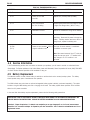
4.3 Troubleshooting .................................................................................................................... EN-45
4.4 Service information ................................................................................................................ EN-45
4.5 Battery Replacement .............................................................................................................. EN-46
4.5.1
Lithium Battery Replacement ........................................................................................ EN-47
4.5.2
Rechargeable NIMH Battery Replacement ..................................................................... EN-47
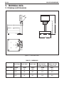
5. TECHNICAL DATA ....................................................................................................................... EN-48
5.1 Drawings and Dimensions .................................................................................................... EN-48
5.2 Technical Data ...................................................................................................................... EN-50
5.3 Specifications ....................................................................................................................... EN-50
CKW-55 CHECKWEIGHER
TABLE OF CONTENTS FOR CKW-55 INDICATOR (Cont.)
EN-3
Page
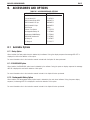
6. ACCESSORIES AND OPTIONS ..................................................................................................... EN-51
6.1 Available Options .................................................................................................................. EN-51
6.1.1 Relay Option ................................................................................................................... EN-51
6.1.2 RS485/422 Option .......................................................................................................... EN-51
6.1.3 Rechargeable Battery option ............................................................................................ EN-51
APPENDIX A MAKING CONNECTIONS TO THE INDICATOR ................................................................... EN-53
A.1 Load Cell Connections ........................................................................................................... EN-53
A.2 Jumper Positions .................................................................................................................. EN-54
A.3 Interface Connections ............................................................................................................ EN-54
A.3.1 Connecting RS232 Interface Cable ................................................................................... EN-54
A.3.2 Connecting External Input Device (Not supplied) .............................................................. EN-54
APPENDIX B LEGAL FOR TRADE ...................................................................................................... EN-55
B.1 Setup Procedure ................................................................................................................... EN-55
B.2 Locking Metrological Parameters ........................................................................................... EN-55
B.3 Verification ............................................................................................................................ EN-56
B.4 Sealing
............................................................................................................................ EN-56
APPENDIX C CKW INDICATOR MOUNTING ......................................................................................... EN-59
APPENDIX D SERIAL COMMUNICATION ........................................................................................... EN-61
D.1 Interface Commands ............................................................................................................. EN-61
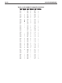
APPENDIX E CAPACITY AND GRADUATION TABLE ............................................................................ EN-62
Limited Warranty ........................................................................................................................... EN-63
EN-4
CKW-55 CHECKWEIGHER
List of Tables
Table Number
3-1
3-2
4-1
4-2
5-1
6-1
6-2
D-1
E-1
Title
Parts and Controls
Control Functions
Geographical Adjustment Values
Troubleshooting
Dimensions
Accessories and Options
ASCII Number to Character Conversion
Serial Interface Command Table
Capacity and Graduation Table
Page
EN-8
EN-10
EN-43
EN-45
EN-48
EN-51
EN-52
EN-61
EN-62
Figure Number
3-1
3-2
3-3
4-1
5-1
5-2
5-3
A-1
A-2
A-3
B-1
B-2
B-3
B-4
B-5
C-1
Title
Indicator
Scale
Control Panel
RTC Battery Removal/Installation
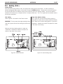
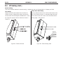
CKW Series Scale
CKW-55 Indicator Table Mount Position
CKW-55 Indicator Wall Mount Position
Cable Entry Identification
Printed Circuit Board Connections
Open and Shorted Jumpers
Inside the Indicator Cover
Internal Wire Seal
Internal Sealing Label
External Wire Seal
External Sealing Label
Mounting Bracket Dimensions
Page
EN-8
EN-8
EN-9
EN-46
EN-48
EN-49
EN-49
EN-53
EN-53
EN-54
EN-55
EN-57
EN-57
EN-58
EN-58
EN-60
CKW-55 CHECKWEIGHER
EN-5
1. INTRODUCTION
This manual contains installation, operation and maintenance instructions for the CKW-55 Indicator and CKW Series Scales.
Please read this manual completely before installation and operation.
1.1 Description
The CKW Series is a dedicated static checkweighing product line with enhanced software and simplified user functionality.
Its easy-to-clean, hygienic design and stainless steel construction make it specifically ideal for food processing and other
wet-environment applications.
Behind this instrument stands Ohaus, a leading manufacturer of precision Indicators, Scales and Balances. An Aftermarket
Department with trained instrument technicians is dedicated to providing the fastest service possible in the event this
instrument requires servicing. Ohaus also has a Customer Service Department to answer any inquiries regarding
applications and accessories.
1.2 Features
Major features include:
• Up to 20,000 maximum displayed resolution
• Stainless steel enclosure with NEMA 4X / IP66 protection
• Stainless steel 2-way table/wall mount bracket included, (Indicator only configuration)
• Supports up to four 350 ohm analog load cells
• High-contrast 0.8"/20 mm high, 6-digit, 7-segment LED weight display with adjustable brightness
• Configurable 3-color, 24-segment LED over-accept-under checkweigh indication with audible signal
• Numeric keypad and 7-function membrane switch operation with optional function lockouts
• One-button checkweigh target set point entries by weight range, variance, or % offset from target
• Flexible unit switching: kg, g, lb, oz, lb:oz, %
• Fast < 2-second display update speed
• 20-part library storage for: Product ID no., Minimum, Maximum, Target and Tare values
• GMP, Time/Date, Auto-Tare, Accumulation, Average and Standard Deviation
• Geographical adjustment function for remote calibration and certification in applicable areas
• Bi-directional RS232 interface
• User-configurable external input connection for remote tare, zero, print and other operations
• Universal switching power supply: nominal 100-240 V ac, 50-60 Hz
• Scale models include a tubular column: 304 stainless steel, 11.8" / 300 mm fixed height with indicator and base
mounting brackets
Optional features include:
• RS485/422 Serial Communication
• AC/DC Relay output
• Internal rechargeable nickel metal hydride (NiMH) battery
EN-6
CKW-55 CHECKWEIGHER
1.3 Safety Precautions
For safe and dependable operation of this equipment, please comply with the following safety precautions:
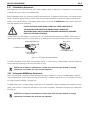
• Verify that the input voltage range printed on the data label matches the local AC power to be used.
• Make sure that the power cord does not pose a potential obstacle or tripping hazard.
• Use only approved accessories and peripherals.
• Operate the equipment only under ambient conditions specified in these instructions.
• Disconnect the equipment from the power supply when cleaning equipment .
• Do not operate the equipment in hazardous or unstable environments.
• Do not immerse the equipment in water or other liquids.
• Do not drop heavy loads on the platform.
• Service should only be performed by authorized personnel.
• This equipment is supplied with a grounded power cable. Use only with a compatible grounded power outlet.
1.3.1 Relay Option Safety Precautions
This equipment may have an optional AC or DC Relay Option board installed. This option allows external device control to
be coordinated to the Indicator’s bar graph settings.
CAUTION: ELECTRICAL SHOCK HAZARD. REMOVE ALL POWER CONNECTIONS TO THE
INDICATOR BEFORE SERVICING OR MAKING INTERNAL CONNECTIONS. THE HOUSING
SHOULD ONLY BE OPENED BY AUTHORIZED AND QUALIFIED PERSONNEL, SUCH AS AN
ELECTRICAL TECHNICIAN.
Before making connections to the Relay terminals, remove power from the system. If the system contains an optional
rechargeable battery system, be sure that the ON/ZERO Off button is used to fully turn off the system after removing the AC
power plug.
More detailed installation instructions are included with the Relay Option Kit when purchased.
CKW-55 CHECKWEIGHER
EN-7
2. INSTALLATION
2.1 Unpacking and Checking
Unpack and verify that the following components have been included:
• CKW-55 Indicator
• Instruction Manual
• 2-way Mounting Bracket (with stand-alone indicator)
• Weights and Measures Kit
• Complete Scale models also include:
o Column
o Base Assembly
o CKW Base Instruction Manual
• Warranty Card
Retain all of the original packaging materials in the event the unit has to be transported or stored.
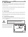
2.2 Selecting the Location
This equipment should be used in an environment free from vibration, temperature extremes or highly corrosive conditions.
These factors may affect normal operation of the unit.
Scale bases used with the CKW-55 Indicator must be located on a stable level surface and kept away from vibrating sources
such as large machinery or appliances.
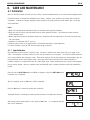
Adjust the leveling feet so that the bubble is centered in the
circle of the level indicator located in the rear of the scale.
Note: Ensure that the scale is level each time its location is changed.
2.3 Connecting Power
2.3.1 AC Power
Plug the AC power cord into a properly grounded power outlet. The CKW Indicator utilizes a universal switching power
supply that operates from 100 to 240 VAC / 50 to 60 Hz.
2.3.2 Battery Power (Optional equipment)
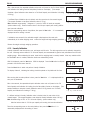
The scale can be operated on the internal rechargeable battery when AC power is not available. The scale will automatically
switch to battery operation if there is a power failure or the power cord is removed. A fully charged battery can operate the
scale for over 10 hours independent of the AC power line. When the battery requires charging, Lo Bat is displayed during
operation. The scale will automatically turn off when the battery is fully discharged.
With AC power applied to the scale, the bar graph may start flashing a yellow bar segment indicating charging is in
progress. As the battery is charged, the segments on the bar graph continue to advance until the first green segment is
reached. A flashing green segment indicates that the battery is fully charged.
Before using the scale on battery power for the first time, the internal rechargeable battery requires charging for
up to 14 hours. The scale can be operated on AC power during the charging process. The battery is
protected against over charging and the scale can remain connected to the AC power line.
EN-8
CKW-55 CHECKWEIGHER
CAUTION
BATTERY IS TO BE REPLACED ONLY BY AUTHORIZED SERVICE PERSONNEL.
RISK OF EXPLOSION CAN OCCUR IF REPLACED WITH THE WRONG TYPE OR CONNECTED
IMPROPERLY.
CAUTION:: Do not dispose of used batteries in normal trash. Follow the proper
disposal or recycling requirements in accordance with local laws and regulations.
2.4 Initial Calibration
Scales are factory calibrated prior to shipping. If calibration is required, refer to section 4.1.
3
OPERATION
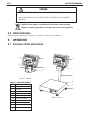
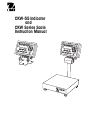
3.1 Overview of Parts and Controls
3
4
4
T
2
1
5
1
6
7
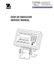
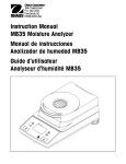
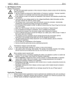
Figure 3-1. Indicator.
8
TABLE 3-1. PARTS AND CONTROLS.
Item
Description
9
1
2
Adjusting Knob
I/O Ports
10
3
4
Control Panel
Indicator Case
5
6
AC Power Input
Table/Wall Bracket
7
8
Column
Level Indicator
9
10
Weighing Platform
Adjusting Feet
Figure 3-2. Scale.
CKW-55 CHECKWEIGHER
3.1
EN-9
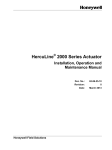
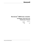
Overview of Parts and Controls (Cont.)
12
13
25
11
24
23
14
15
22
21
20
19
18
17
16
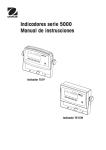
Figure 3-3. Control Panel.
TABLE 3-1. PARTS AND CONTROLS (Cont.).
Item Description
11
Weight Display
12
13
Checkweigh Bar Graph
Capacity Label Window
14
15
Numeric Keypad
C clear button
16-22 Control Buttons See Table 3-2
23
Weighing Units, Brutto/Gross, Net, Tare, Preset Tare Indicators
24
25
Stable Indicator
Center of Zero Indicator
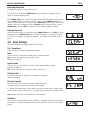
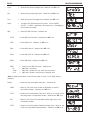
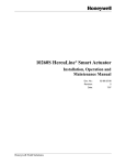
PRINT
• Turns the
indicator on.
Menu
• Enters menu
mode.
• Displays gross,
net and tare
values.
G/N/T
• Saves pre-set
tare after
numeric entry.
• Performs tare
operation.
TARE
Navigation Function
No
Yes
Exit
Back
(Menu Mode)
• Enters the current • Advances to the • Moves backwards • Exits the present
through upper
next menu.
menu shown on
mode and returns
and medium
the display.
directly to the
level menus.
• Rejects the
weighing mode.
current setting on
• Accepts the
current setting on the display and • Backs out of
lower level
advances to the
the display.
menus and
next available
settings.
setting.
Units
• Changes the
weighing unit.
• Sends current
display value to
the serial
interface.
• If indicator is on,
sets zero.
ON/ZERO
Off
Secondary Function
(Long Press)
• Turns indicator
off.
Primary Function
(Short Press)
Secondary Function
Navigation Function
Primary Function
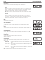
Save
• With Library
mode on, saves
library data and
loads to active
weighing mode.
• With Library
mode on,
initiates library
view/entry/edit
sequence.
LIBRARY
• With checkweigh
mode on,
initiates target
view/entry/edit
sequence.
TARGET
• Displays
statistical
information of
accumulated
weighing
memory.
• Toggles numeric
• Saves and steps
data entry
between + and -. through target
data.
• Adds displayed
weight into
accumulation
memory.
NEXT+/-
3.2
TABLE 3-2. CONTROL FUNCTIONS.
EN-10
CKW-55 CHECKWEIGHER
Control Functions
CKW-55 CHECKWEIGHER
3.3
EN-11
Menu
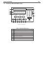
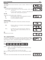
3.3.1 Menu Structure
CALIBRATION (Sec. 4.1)
Span
Linearity
Calibration Test
Perform
Perform
Perform
Geo Factor:
End
0…16...19…31
MODE (Sec. 3.6.3)
Reset:
Checkweigh:
No, Yes
Off, On
Library:
Set Point Input:
Beeper Signal:
Off, On
Range, Variance, %
Off, Accept, Under,
Over, Under-Over
Display Signal:
Off, Accept, Under,
Over, Under-Over
Graph Increment: Scaled, Auto, User
Graph Display:
Segment, Bar, Block
End
SETUP (Sec. 3.6.1)
Reset:
Legal-For-Trade:
Calibration Unit:
FS Capacity:
No, Yes
Off, On
kg, lb
Numeric Entry
Graduation:
Zero Range:
Retain Zero Data:
Auto-Tare:
Numeric Entry
2%,18%, 100%
Off, On
Off, On, On Acc
Beep Volume:
Key Beep:
End
Off, Lo, Hi
Off, On
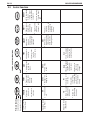
Units, GNT, Accumulation, Start-Stop,TareStart-Stop
Off, On
Input Beep:
Relay Output:
Type, Sequence, Contact,
Stable
Reset:
Unit:
No, Yes
kg, lb, g, oz, lb:oz, %
Stable Range:
Averaging Level:
Auto-0 Tracking:
LED Brightness:
.5d, 1d, 2d, 5d
Lo, Med, Hi
Off, .5d, 1d, 3d
Off, Lo, Med, Hi
Bar Brightness:
Power Saver:
End
Off, Lo, Med, Hi
Sleep, Auto-off
COM (Sec. 3.6.5)
PRINT (Sec. 3.6.4)
Reset:
No, Yes
Stable Only:
Off, On
Auto Print Mode: Off, Stable, Interval,
Continuous, On Accept
Print Content:
Display, Numeric,
Header, Setpoint,
Gross, Net, Tare,
Status, GMP,
Accumulation
Layout:
Format, Feed
List:
Menu, Library
End
Reset:
Baud Rate:
Parity:
No, Yes
300, 600, 1200, 2400,
4800, 9600,19200
None, Even, Odd
Data Length:
Stop Bit:
Handshake:
Type:
7, 8
1, 2
None, XON/XOFF
RS232, RS485
Alt Command: Print, Tare, Zero
End
GMP (Sec. 3.6.7)
I/O (Sec. 3.6.6)
Reset:
No, Yes
External Input: Off, Tare, Zero, Print,
READOUT (Sec. 3.6.2)
LOCK (Sec. 3.6.8)
Reset:
User ID:
Project ID:
No, Yes
Enter 6 characters
Enter 6 characters
Menu:
Scale ID:
Date:
Time:
End
Enter 6 characters
Format, Set
Format, Set
Key Function:
Reset, Cal, Setup, Read,
Mode, Print, Com, I/O,
GMP Data
Reset, Num, Clr, Target,
Lib, Lib Save, Next, Zero,
Print, Units, GNT, Tare,
Menu
End
End
NOTES: 1.
2.
3.
4.
5.
Bolded items indicate factory default settings.
The unit selected for “Calibration Unit” will become the default “On” unit in the event that all other units are set to “Off”.
When the Legal for Trade setting is changed to “On”, the following items are affected:
i. Span and Linearity calibration are unavailable, Geo factor is viewable but not alterable, Cal Test will operate.
ii. Underlined menu items become forced as default.
Some menu items may only become available when certain optional accessories are installed.
Using the Reset function in the “SETUP” menu will not change the values entered for FS Capacity or Graduation.
EN-12
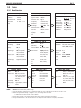
3.3.2
CKW-55 CHECKWEIGHER
Menu Navigation
TO ENTER THE MENU MODE
Press and hold the Menu button until MENU appears on the display. The first upper level menu CAL appears on the display.
Summary of button navigation functions in menu mode:
--Yes - Allows entry into the displayed menu.
- Accepts the displayed setting and advances to the next menu item.
--No
- Skips by the displayed menu.
- Rejects the displayed setting or menu item and advances to the next available item.
--Back - Moves backwards through the upper and middle level menus.
- Backs out of a list of selectable items to the previous middle level menu.
--Exit - Exits from menu directly to the active weighing mode.
3.4 Turning Indicator On/Off
3.4.1 Turning On
With the scale off, press the ON/ZERO Off button. The Indicator performs a display-test, momentarily indicating model, option
and status information, and then goes into the active weighing mode.
3.4.2 Turning Off
To turn the Indicator off, press and hold the ON/ZERO Off button until OFF is displayed.
3.4.3 Stabilization
Before initially using the indicator, allow time for it to adjust to its new environment. The recommended warm-up period is
five (5) minutes after the scale has stabilized to room temperature.
CKW-55 CHECKWEIGHER
EN-13
3.5 Application Modes
Before using the CKW-55 Indicator, make sure it has been properly set up and calibrated (refer to Sections 3.3.2 Menu
Navigation and Section 3.6.1 Setup Menu).
If the unit is received as a scale, it has been factory calibrated and can be operated at this point using the factory default
settings. To ensure optimal accuracy, Ohaus recommends that the Scale be re-calibrated before use (refer to Section 4.1 for
Calibration and Appendix B Legal for Trade Sealing if required).
3.5.1 Weighing
Zero Operation
Press the ON/ZERO Off button to zero the weight display. The scale must be stable to accept
zero operation.
%
kg
lb
g
oz
B/G
Net
Tare
PT
%
kg
lb
g
oz
B/G
Net
Tare
PT
%
kg
lb
g
oz
B/G
Net
Tare
PT
%
kg
lb
g
oz
B/G
Net
Tare
PT
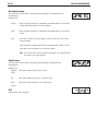
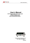
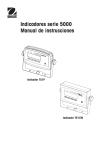
Basic Weighing
Place the item to be weighed on the Scale platform. The illustration indicates a sample of
1.5 kg, Gross weight.
Manual Tare
When weighing an item that must be held in a container, taring stores the container weight
into the Indicator’s memory. Place the empty container to be tared on the scale platform
(example 0.5 kg).
Press the TARE button. The container weight is tared. The display will show 0 kg, Net
weight.
To clear the Tare value, empty the scale platform (the display will show the tare weight as a
negative value). Press the TARE button. Display will show 0 kg, Gross weight.
Pre-Set Tare
A Pre-set Tare (PT) is a known tare value entered through the numeric keypad. The PT value
will supersede any other Tare or PT value in memory. (When using Pre-Set Tare, make sure
that Auto-Tare function is set off in the Setup menu.)
To initiate a Pre-set Tare, enter a numeric value using the keypad (example 1.000 kg), then
press the TARE button.
Display will show the Pre-set Tare as a negative value, with the PT indicator on.
Notes: 1.If the TARE button is not pressed 5 seconds from the last numeric entry, the
display returns to the previous mode without a tare being stored.
2.To clear a Pre-set Tare value, empty the pan then press the TARE button.
The display will return to 0 kg, Gross weight.
%
kg
lb
g
oz
B/G
Net
Tare
PT
%
kg
lb
g
oz
B/G
Net
Tare
PT
EN-14
CKW-55 CHECKWEIGHER
Auto-Tare
Auto-Tare automatically tares the initial weight (such as a container) placed on the empty platform, without having to press
the TARE button. The tare value is cleared automatically when the weight on the pan is fully removed.
In Auto-Tare mode, the Tare indicator blinks when waiting for a Tare item to be placed on the empty scale platform (with
LFT On, there is no flashing Tare indicator).
When the On Accept setting is selected, weight values that are within the accept range will be tared automatically.
Note: Auto-Tare supersedes any pre-set (PT) value in memory.
Displaying Gross, Net, Tare
When a tare has been entered, pressing the G/N/T Menu button successively displays the Tare, the Gross, and the Net
weights. After a few seconds the scale automatically reverts to displaying the NET weight.
Changing Units of Measure
Press and hold the PRINT Units button until the desired measuring unit appears. Only measuring units enabled in the
Readout-Unit Menu will be displayed (refer to Section 3.6.2).
Printing Data
Printing the displayed data to a printer or sending the data to a computer requires that the communication parameters in the
Print and Communication Menu are set (refer to Sections 3.6.4 and 3.6.5).
Press the PRINT Units button to send the displayed data to the RS232 port (the Auto-Print Mode in Section 3.6.4 function
must be Off).
Note: If the PRINT Units button is pressed too long, the display advances to another measuring unit without sending the
print data.
CKW-55 CHECKWEIGHER
EN-15
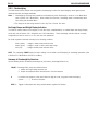
Accumulation Operation
The Accumulation function is always on and allows basic statistical information to be collected from multiple weighings.
Accumulated data collected includes total count (or number of samples), total sample weight, average sample weight, and a
standard deviation of sample weight. The information continues to accumulate and is retained until cleared or the scale is
turned off.
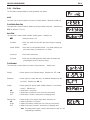
To add a weight value to the Accumulation memory, place the item on the platform, then short
press the NEXT +/- button. M-ADD is momentarily flashed on the display to indicate that the
value is added into memory. Repeat this step for each additional item.
To view the Accumulation data, long press the NEXT +/-- button. Accumulation data is displayed
momentarily in the following sequence:
Display parameter COUNT, then the total number of weighed samples (example 150).
Display parameter TOTAL, then the total accumulated weight value (example 1504.05 kg).
%
kg
lb
g
oz
B/G
Net
Tare
PT
Display parameter AVG, then the calculated average of the accumulated values (example
10.03 kg).
%
kg
lb
g
oz
B/G
Net
Tare
PT
%
kg
lb
g
oz
B/G
Net
Tare
PT
Display parameter S-DEV (standard deviation), then the calculated standard deviation
(example 4.502 kg).
Display END, then the display returns to the active weighing mode.
To clear the Accumulation memory, press the C button during the display sequence. At the end
of the display sequence, CLEAR is displayed and returns to active weighing mode.
Notes: 1. If a value exceeds the size of the 6 digit display, the number will first be displayed in
reduced decimal places, after this, the g and lb:oz units may be changed to kg and lb
units. If the value still exceeds the display digits, Err will be displayed. The correct
value with the original weighing unit will always be printed when the Accumulation
data is printed.
2. I/O- External Input setting should NOT be set to: S-S or T-S-S (refer to Section 3.6.6),
since this menu setting also controls the functionality of the NEXT +/- button. The
accumulate function is not available if either of these I/O selections are made.
EN-16
CKW-55 CHECKWEIGHER
3.5.2 Checkweighing
The CKW Series features multiple user-configurable checkweighing functions that permit weighing items against preset
minimum-maximum and target parameters.
Notes: 1. Checkweighing and target entry operations are enabled only when Checkweigh is turned on in the Mode Menu
(refer to Section 3.6.3, Mode Menu). When enabled from the menu, Checkweigh mode is automatically active
upon exiting from the Mode Menu.
2.The weight of the item being checked is net of any Tare or Pre-set Tare value.
Bar Graph, Beeper and Weight Display Indication
The CKW-55 Indicator features a 24-segment, 3-color Bar Graph, complemented by an audible Beeper and Weight Display
visual alert (refer to Sections 3.6.1 Setup Menu and 3.6.3 Mode Menu). These checkweigh indication features are easily
configurable and can be turned on or off to suit most user preferences.
Bar Graph segments illuminate according to the following conditions:
Under (yellow)
Accept (green)
= weight is below preset minimum value.
= weight is equal or within preset target range.
Over (red)
= weight exceeds preset maximum value.
NOTE: The checkweigh TARGET button and menu settings can be locked to resist tampering of checkweigh parameters (refer
to Sections 3.6.3 Mode Menu and 3.6.8 Lock Menu).
Summary of Checkweigh Key Functions
Use the following buttons to establish checkweigh set point values (Checkweigh Mode is on).
TARGET Checkweigh Start, Accept and Advance button.
1. Initiates the Target setting sequence and
2. Accepts the displayed values and advances to the next sequence.
C
In numeric entry sequence, short press clears one digit at a time, long press erases the display
(shows - - - - - - ). Re-enter a new value.
NEXT +/- Toggles the displayed value being entered between negative and positive.
CKW-55 CHECKWEIGHER
Programming Accept Range by Numeric Key Entry
In the Mode menu, set Checkweigh to On and Set Point Input to Range (refer to Section 3.6.3).
NOTE: The under and over set points are included in the Accept range.
Press the TARGET button to initiate check weigh entry sequence. UNDER flashes momentarily
to indicate the first parameter to be entered. The last Yellow and the first Green Bar Graph
segments are lit during entry.
The display flashes the last Minimum range value entered. Use the numeric keypad to enter
a new Minimum range value.
Note: -NO- is displayed if the entered value is out of range or is not compatible with the
graduation settings, (refer to Section 3.6.1).
Press TARGET to accept the entry. The display will freeze momentarily to confirm the entry.
OVER flashes momentarily to indicate the parameter to be entered next. The last Green and
the first Red Bar graph segments are lit during entry.
The display flashes the last maximum range value entered. Use the numeric keypad to enter
a new Maximum range value or press C to clear. .
Press TARGET to accept the entry. The display will freeze momentarily to confirm the entry.
END appears momentarily to confirm end of checkweigh entry sequence. The Indicator
returns to active checkweighing mode.
NOTES: 1.Values entered can be from 1d to Full Scale capacity.
2.Minimum range value cannot be greater than maximum range value unless both
values are negative.
3.For entry in the lb:oz units, the first decimal point entered is used as the lb oz
separator, (eg. an entry of 2.08.3 = 2 lb 8.3 oz. At least one digit must be
entered for the lb location, eg., an entry of 0.15.9 = 0 lb 15.9 oz.
EN-17
EN-18
CKW-55 CHECKWEIGHER
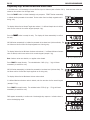
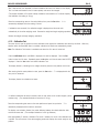
Programming Target, Minimum and Maximum Variance Values
In the Mode menu, set Checkweigh to On and Set Point Input to Variance (refer to Section 3.6.3). Under and over values are
entered as the variance from the target value.
Press the TARGET button to initiate checkweigh entry sequence. TARGET flashes momentarily
to indicate the first parameter to be entered. The two center Green bar Graph segments are lit
during entry.
The display flashes the last Accept Target value entered. If a different Accept value is desired,
enter the new value via the numeric keypad (example 4 kg).
%
kg
lb
g
oz
B/G
Net
Tare
PT
%
kg
lb
g
oz
B/G
Net
Tare
PT
%
kg
lb
g
oz
B/G
Net
Tare
PT
Press the TARGET button to accept the entry. The display will freeze momentarily to confirm
the entry.
VAR UN flashes momentarily to indicate the parameter to be entered next (Variance-Under). The
last Yellow and the first Green Bar Graph segments are lit during entry.
The display flashes the last Minimum Variance value entered. If a different Minimum Variance
value is desired, enter the new value via the numeric keypad (example 1 kg).
Note: Variance values are absolute, no negative value allowed.
Press TARGET to accept the entry. The calculated value 3.000 (4 kg – 1 kg) will freeze
momentarily to confirm the entry.
VAR OV flashes momentarily to indicate the parameter to be entered next (Variance-Over). The
last Green and the first Red Bar Graph segments are lit during entry.
The display flashes the last Maximum Variance value entered.
If a different Maximum Variance value is desired, enter the new value via the numeric keypad
(example 1.5 kg).
Press TARGET to accept the entry. The calculated value 5.500 (4 kg + 1.5 kg) will freeze
momentarily to confirm the entry.
%
kg
lb
g
oz
B/G
Net
Tare
PT
%
kg
lb
g
oz
B/G
Net
Tare
PT
END appears momentarily to confirm end of checkweigh entry sequence. Indicator returns to
active checkweighing mode.
CKW-55 CHECKWEIGHER
EN-19
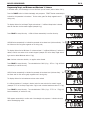
Programming Target, and Minimum and Maximum % Variance
In the Mode menu, set Checkweigh to On and Set Point Input to Percent (refer to Section 3.6.3).
Press the TARGET button to initiate checkweigh entry sequence. TARGET flashes momentarily to
indicate the first parameter to be entered. The two center green Bar Graph segments are lit
during entry.
The display flashes the last Accept Target value entered. If a different Accept value is desired,
enter the new value via the numeric keypad (example 4 kg).
%
kg
lb
g
oz
B/G
Net
Tare
PT
%
kg
lb
g
oz
B/G
Net
Tare
PT
Press TARGET to accept the entry. 4.000 will freeze momentarily to confirm the entry.
VAR UN flashes momentarily to indicate the parameter to be entered next (Variance-Under). The
last Yellow and the first green segments are lit during entry.
The display flashes the last Minimum % variance entered. If a different Minimum % variance is
desired, enter the new value via the numeric keypad (example 25% of the Accept Target value 4
kg to reach a desired Minimum value of 3 kg).
%
kg
lb
g
oz
B/G
Net
Tare
PT
%
kg
lb
g
oz
B/G
Net
Tare
PT
%
kg
lb
g
oz
B/G
Net
Tare
PT
%
kg
lb
g
oz
B/G
Net
Tare
PT
Note: Variance values are absolute, no negative value allowed.
Press TARGET to accept the entry. The calculated value 3.000 (4 kg – 25% or 1 kg) will freeze
momentarily to confirm the entry.
VAR OV flashes momentarily to indicate the parameter to be entered next (Variance-Over). The
last Green and the first red bar graph segments are lit during entry.
The display flashes the last maximum variance value entered.
If a different maximum % variance is desired, enter the new value via the numeric keypad
(example 37.5% of the Accept Target value 4 kg to reach a desired maximum value of 5.5 kg).
Press TARGET to accept the entry. The calculated value 5.500 (4 kg + 37.5 % or 1.5 kg) will
freeze momentarily to confirm the entry.
END appears momentarily to confirm end of checkweigh entry sequence. Indicator returns to
active checkweighing mode.
%
kg
lb
g
oz
B/G
Net
Tare
PT
EN-20
CKW-55 CHECKWEIGHER
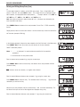
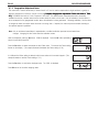
Normal Checkweighing Operation
Normal checkweighing is used to determine when the weighed sample is within the target
range. In this example, Target range settings are Under 3 kg and Over 5.5 kg.
If a container is used, tare it first.
%
kg
lb
g
oz
B/G
Net
Tare
PT
%
kg
lb
g
oz
B/G
Net
Tare
PT
Place the item to be weighed on the scale platform. The illustration indicates a sample
weight of 4.25 kg. The bar graph display indicates weight is within the Accept range.
Negative Checkweighing Operation
Negative checkweighing is used to determine when the removed material is within the Target
range. Press the TARGET button and set the Under and Over values as a negative value.
This is done by entering the number first, then pressing the +/- button. In this example,
Target range settings are Under -3 kg and Over -4.5 kg.
Place the item to be weighed on the scale platform. The illustration indicates a sample of
5.25 kg, Gross weight.
%
kg
lb
g
oz
B/G
Net
Tare
PT
%
kg
lb
g
oz
B/G
Net
Tare
PT
%
kg
lb
g
oz
B/G
Net
Tare
PT
Tare the weight of the item.
Remove a portion of the item. The illustration indicates the removal of a 3.5 kg portion. The
bar graph display indicates weight is within the Accept range.
CKW-55 CHECKWEIGHER
EN-21
Zero Checkweighing Operation
Zero Checkweighing is used when comparing subsequent samples to an initial reference
sample. Press the TARGET button to set target to zero, then set the Variance Under and Over
values. In this example, Under and Over values are 0.050 kg.
Note: Any number entered for the Under value will automatically be a negative number.
Place the item representing the reference weight on the scale platform. The illustration
indicates1 kg.
%
kg
lb
g
oz
B/G
Net
Tare
PT
%
kg
lb
g
oz
B/G
Net
Tare
PT
%
kg
lb
g
oz
B/G
Net
Tare
PT
Tare the reference sample.
Remove the reference sample from the platform.weight. In this example, any weight that is
0.050 kg or more below 1 kg will display UNDER.
Place the item to be compared on the scale platform. The illustration indicates that the
sample is 0.020 kg above the 1 kg reference weight and is within the accept range.
%
kg
lb
g
oz
B/G
Net
Tare
PT
EN-22
CKW-55 CHECKWEIGHER
3.5.3 Library Operation
The CKW-55 Indicator allows the storage of checkweighing data in 20 Library locations, designated ID 01 to ID 20. Each
Library location includes: a Part Number or name, Pre-set Tare, Maximum, Minimum, and Target value. Data entered into the
libraries can be recalled for use, edited or deleted.
The LIBRARY Save button can be locked to prevent unauthorized changes to the data (refer to Section 3.6.8 Lockout Menu).
Summary of Library Key Functions
Use the following buttons to establish checkweigh set point values (Checkweigh Mode and Library is on).
LIBRARY Save
Short Press
1. Initiates the Library sequence, and
2. Accepts the displayed values and advances to the next sequence.
Long Press during part number display or while END is displayed loads the library data, and exits to
active weigh mode.
NEXT +/-
1. During a Library ID display, short press advances to the next higher Library ID.
2. Long press will begin scrolling through Lib ID’s more quickly.
3. During Part Number entry, converts a 3 digit ASCII code to an alpha-numeric character.
4. During numeric value entry sequence, short press toggles the displayed value between negative and
positive.
C
1. Short press in numeric entry sequence, clears one digit at a time. A long Press during data entry
erases all digits.
2. While END is displayed, a long press will erase the data in the selected library.
Exit
Exits any Library function.
Entering and Editing Library Data
In the Mode menu, Library should be On. Library data is viewed in the Set Point Input setting as it was entered. In this
example, Set Point Input setting is Variance.
Note: In Library entry mode, LIBRARY Save is used to confirm and advance to the next setting instead of TARGET button..
Press the LIBRARY Save button to display the last active Library ID.
To choose another Library ID location, press the NEXT +/- button. The next Library ID location
flashes, then the corresponding Part Number.
Display shows a flashing - - - - - - to indicate that there is no existing Part Number specified
for this Library ID location. For improved identification, an identifying part number or product
ID may be entered.
Enter the desired Part Number (up to 6 digits + 6 decimal points) (example 30123.0) using
the numeric keys.
CKW-55 CHECKWEIGHER
EN-23
Entering and Editing Library Data (Cont.)
or
To enter letters instead of numbers, use the ASCII entry format: Enter a 3 digit ASCII code
shown in Table 6-2, then press NEXT+/- button. The 3 digits convert to an equivalent single
ASCII character, non-displayable ASCII codes produce “_”. (Example: HAM-6 = 072, NEXT +/-,
065, NEXT +/-, 077, NEXT +/-,109, NEXT +/-, 045, NEXT +/-, 6.)
Note: two entries are required to make the letter M or W. (Use upper case followed by the
lower case ASCII code value).
Press LIBRARY Save and advance to the next parameter: Pre-set Tare. P-TARE momentarily
flashes.
Display flashes 0.000 or the last value entered. Use the numeric keys to enter the desired Preset Tare value (example 0.500 kg).
%
kg
lb
g
oz
B/G
Net
Tare
PT
%
kg
lb
g
oz
B/G
Net
Tare
PT
In the following example, Variance has been selected as the Set Point Input in the Mode menu.
Press LIBRARY Save to save the current entry and advance to the next parameter:
TARGET momentarily flashes.
Notes: 1. - - - - - - is displayed if no previous data was specified for the respective
parameters.
2. Use the C button to clear previous data.
Enter the desired value (example 4 kg) using the numeric keys.
Press LIBRARY Save to save the current entry and advance to the next parameter: VAR UN
(Variance-Under).
Note
Note: Variance values are absolute, no negative value allowed.
Enter the desired Minimum tolerance value (example 1 kg) using the numeric keys.
Press LIBRARY Save to accept the entry. The calculated value 3.000 (4 kg – 1 kg) will freeze
momentarily to confirm the entry.
Advance to the next parameter: VAR OV (Variance-Over). VAR OV flashes momentarily. The
last Green Bar Graph and the first Red segment are displayed during entry.
Enter the desired Maximum tolerance value (example 1.5 kg) using the numeric keys.
EN-24
Entering and Editing Library Data (Cont.)
Press LIBRARY Save to accept the entry. The calculated value 5.500 (4 kg + 1.5 kg) will
freeze momentarily to confirm the entry.
Display -END- indicates end of Library entry sequence.
To review data entries before saving, short press LIBRARY Save to cycle through entries.
Long press LIBRARY Save to save and exit to active weighing mode. While exiting the
weighing mode, the Library ID SAVED and READY is momentarily displayed.
OR
To cancel the entries, short press the C button while END is displayed. While exiting to the
weighing mode, CANCEL is momentarily displayed. Data entries are not saved and the
original data are retained.
Loading an Existing Library to the Active Checkweigh Mode
Press the LIBRARY Save button. The last Library ID momentarily flashes followed by the part
number or name assigned.
To advance to another Library ID, repeatedly press the NEXT +/- button until the desired
Library is reached.
To load the selected Library ID, long press LIBRARY Save. While exiting to the weighing
mode, the Library ID and READY are displayed.
Note: If no button is pressed within 30 seconds, no changes are retained and the display
returns to the weighing mode.
CKW-55 CHECKWEIGHER
CKW-55 CHECKWEIGHER
Reviewing Library Data
To review Library data, the Library must be set On.
If the library is Off, pressing the LIBRARY Save button will display the message -NO-, and
returns to the active weighing mode.
Press LIBRARY Save button, the last active Library location and Part Number will be displayed.
Press the NEXT +/- button to advance to another Library, or press LIBRARY Save button to
review the current Library data. Continue to press LIBRARY Save button until all data has been
reviewed. When END is displayed, press the TARE Exit button to cancel and exit, or press
LIBRARY Save button then NEXT +/- button to continue reviewing additional Libraries.
Erasing Library Data
Access the desired Library to be removed using the LIBRARY Save button and NEXT +/- button.
Repeatedly press the LIBRARY Save button until END is displayed. Long press the C button,
the Library ID is displayed, then CLEAR is displayed. The contents of the selected Library is
erased.
3.6 Scale Settings
This section describes the settings available in each menu.
3.6.1 Setup Menu
Access this Menu to configure metrological parameters.
Reset
This menu item is used to reset the Setup menu to the factory defaults.
Note: Capacity and graduation settings are not reset.
Selections are: No, Yes
Legal for trade
This menu item is used to enable or disable Legal for trade compliant operation.
Selections are: OFF, On.
Note: Certain menu items are restricted as shown in Section 3.3.1.
Calibration Unit
This menu item is used to define the unit of measure for calibration.
Selections are: kg, lb.
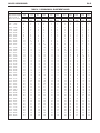
Full Scale Capacity
This menu item is used to define the capacity setting of the scale.
The display flashes the last Full Scale Capacity value entered.
If a different Full Scale Capacity value is desired, enter the new value via the numeric keypad.
Values entered are whole numbers from 1 to 100,000 (refer to Appendix E for typical values).
Note: Changes will require a re-calibration for correct operation.
Graduation
This menu item is used to define the scale readability. The display flashes the last Graduation
value entered. If a different Graduation value is desired, enter the new value via the numeric
keypad.
EN-25
EN-26
CKW-55 CHECKWEIGHER
Notes:
1.Values entered must be submultiples of 1, 2 or 5, and between 0.0001 to 50, (refer to Appendix E for typical values).
2.Full Scale Capacity and Graduation combinations may not exceed 20,000 divisions for CKW-55 Indicators or 6000 to
7500 divisions for CKW Scales. Invalid entries will result in a display -NO- and will not be saved.
3.With LFT set to ON, Full Scale Capacity and Graduation combinations may not exceed 10,000 for CKW-55 Indicators, or
3,000 for CKW Scales
4.When Full Scale Capacity and graduation combinations exceed the resolution limits, the Graduation value will be
adjusted automatically.
Zero Range
This menu item is used to define the percentage of full capacity load that may be cleared by
pressing the ON/ZERO Off button. Selections are: 2%, 18% and 100%.
Note: With LFT On, Zero Range defaults to 2%.
Retain Zero Data
This menu item is used to enable or disable Retain Zero Data function. When set On, indicator
stores the current zero point and restores it on power-up. Selections are: OFF, On.
Auto-Tare
Selections are:
OFF =
Auto-Tare is Off.
ON =
Auto-tare is On.
ON ACC= Auto-Tare On accept is enabled. When On Acc is selected, a delay value may be
entered using the numeric keypad.
(0.5 - 5)= The value entered must be from 0.5 to 5 seconds.
Beeper Volume
This menu item is used to define the beeper volume. Selections are: HI, LO and OFF.
Beeper Key
This menu item is used to enable or disable the beeper. Selections are: OFF, ON.
End
Represents the end of the menu.
?JW4
CKW-55 CHECKWEIGHER
3.6.2 Readout menu
The Readout menu is used to configure display parameters and adopt the scale to
environmental conditions.
Reset
This menu item is used to reset the Readout menu to factory defaults. Selections are: No, Yes.
Units
This menu item is used to define which units will be enabled for use. Selections are: kg, lb, g,
oz, lb:oz, percent. In the event that all units are set to Off, the unit selected for calibration will
forced ON. After pressing the Yes button, each unit may be set to OFF or ON.
Note: Percent unit is only available with a checkweigh target value. (See Section 3.6.3 ModeSet Point Input and Section 3.5.2 Checkweigh Operation). The displayed value is the percent
relative to the target weight value (example, if a target value is 100 kg, a 100 kg weight is
displayed as 100%, 75 kg is displayed as 75%, 150 kg is displayed as 150%).
Stable Range
This menu item is used to specify a tolerance limit to indicate a Stable condition (Stable
indicator turns on). Selections are: 0.5, 1, 2, 5 (scale divisions).
Averaging Level
This menu item is used to specify how much filtering is used to compensate for vibration or
excessive air currents. Selections are: Lo, Med, Hi.
Auto-Zero Tracking
This menu item is used to define the Auto-Zero Tracking threshold. AZT minimizes the effects of
temperature changes and small disturbances on the zero reading. The scale maintains the zero
display until the threshold is exceeded. Selections are: OFF, 0.5,1, 3 (scale divisions).
Weight Display Brightness Level
This menu item is used to define the brightness of the weight display. Selections are: OFF
(display blank), Lo, Med, Hi.
Bar Graph Brightness Level
This menu item is used to define the brightness of the Bar Graph display. Selections are: OFF,
Lo, Med, Hi.
EN-27
EN-28
CKW-55 CHECKWEIGHER
Power Saver
This menu item is used to enable power saving function. Selections are:
SLEEP
Specifies the number of minutes that the display will remain on in the absence of scale
activity. The display flashes the last Sleep value entered. Values between 0 to 99 are
entered via the numeric keypad. A value of 0 is equal to Sleep mode OFF.
Note: With LFT turned On, the scale must be at center of zero for sleep mode to initiate.
AUTO-OFF
Specifies the number of minutes that the Indicator will remain on in the absence of
scale activity. The display flashes the last value entered. Values between 0 to 99 are
entered via the numeric keypad. A value of 0 is equal to Auto-Off Timer OFF.
END
Represents the end of the menu.
3.6.3 Mode Menu
The Mode menu is used to configure parameters of the available application modes.
Reset
This menu item is used to reset the Mode menu to factory defaults. Selections are: No, Yes.
Checkweigh Mode
This menu item is used to enable or disable the Checkweigh mode. Selections are: OFF, On.
Library Mode
This menu item is used to enable or disable the Library mode.
Selections are: OFF, On.
Set Point Input
This menu item is used to define checkweigh set point formats. (refer to Section 3.5.2).
Selections are:
Range (RNG)
= Acceptance range between a Minimum (under) and Maximum (over)
value.
Variance (VAR)
Percent (PCT)
= Input a Target value and the Minimum and Maximum weight variance
from the Target.
= Input a Target value and the Minimum and Maximum % variance from
the Target.
Note: Changing the set-point input settings clears existing set-point entries.
CKW-55 CHECKWEIGHER
Beeper Signal
This menu item is used to define when beeper sounds an (audible alert) during checkweighing.
Selections are:
= Beeper does not sound.
OFF
Accept
= Beeper sounds when the weighed value is within the Accept range
(corresponding to green LED bar graph area).
Under
= Beeper sounds when the weighed value is below the minimum acceptable
range (corresponding to yellow LED bar graph area)*.
Over
= Beeper sounds when the weighed value exceeds the maximum acceptable
range (corresponding to red LED bar graph area).
Under-Over= Beeper sounds when the weighed value is outside of the Accept range
(U-O)
(corresponding to the yellow and red LED bar graph areas)*.
*Note: When under is indicated, the beeper signal does not sound when the pan is cleared.
Weight Display Signal
This menu item is used to define the checkweigh conditions when the LED weight display flashes
as a visual alert during checkweighing.
Selections are:
OFF
= LED weight display does not flash in any checkweigh condition.
Accept
= LED weight display flashes when the weighed value is within the Accept
range (corresponding to green LED bar graph area).
Under
= LED weight display flashes only when the weighed value is below the
minimum acceptable range (corresponding to yellow LED bar graph area)*.
Over
= LED weight display flashes only when the weighed value exceeds the
maximum acceptable range (corresponding to red LED bar graph area).
Under-Over= LED weight display flashes when the weighed value is outside of the Accept
(U-O)
range (corresponding to the yellow and red LED bar graph areas)*.
*Note: When under is indicated, the display signal does not flash when the pan is cleared.
EN-29
EN-30
CKW-55 CHECKWEIGHER
Bar Graph Increment
This menu item is used to define how the bar graph segments are incremented during
checkweighing.
Selections are:
Scaled
= Each bar graph increment is automatically calculated based on the set point
entries and scaled relative to the scale capacity.
AUTO
= Each bar graph increment is automatically calculated based on the set point
entries.
User
= The value of under and over bar graph increment is set by the user via the
numeric keypad.
When selected, the display flashes the last Increment value entered. Enter a
value within one scale division and full scale capacity.
Note: The user value can be set to represent the weight of a single item which
will display as a single segment.
Graph Display
This menu item is used to define how the bar graph segments are grouped during
checkweighing.
Selections are:
Segment
(SEG)
= Bar graph segment light up one at a time.
Bar
= Bar graph segments light up as a continuous bar.
Block
= Bar graph section will light up as a single block.
(BLOC)
END
Represents the end of the menu.
CKW-55 CHECKWEIGHER
EN-31
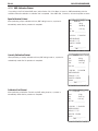
3.6.4 Print Menu
The Print Menu provides settings for printing methods and options.
RESET
This menu item is used to reset the Print menu to factory defaults. Selections are: No, Yes.
Print Stable Data Only
This menu item is used to enable or disable the printing of stable values only. Selections are:
OFF, On (default if LFT is On).
Auto Print
This menu item is used to select automatic printing options. Selections are:
= Auto-print feature is off.
OFF
On Stable
= Prints first stable non-zero value after each change in weighing
value.
Interval (INTRVL)
= Prints data on user-selected intervals. This allows specifying the
print interval times (in seconds from 1 to 3600).
Continuous
= Prints data continuously.
On Accept
= Prints after the reading becomes stable within the Accept area.
(Checkweighing must be active and setup.)
Print Content
This menu item is used to define the content of the printed data.
Selections are:
Display
= Allows printing of the displayed weight. Selections are: OFF or On.
Numerical
= Allows output of numeric data only, no additional descriptive text will
be printed. Selections are: OFF, On.
Header
= Allows printing the pre-set header (OHAUS, Model No., and software
version). Selections are:
OFF
Single
= Header data is not printed.
= Header data is printed only once at the very next printout*.
Cont
= Header data is printed in each printout of weighing result.
Setpoint Data
OFF
Single
Cont
= Allows printing of the Setpoint Input values. Selections are:
= Setpoint Input data is not printed.
= Setpoint Input data is printed once only at the very next printout*.
= Setpoint Input data is printed in each printout of weighing result.
*Note: The Single printout option is reset at each power on cycle, or if the
single setting is reselected.
EN-32
CKW-55 CHECKWEIGHER
Gross
=
Allows printing the Gross weight value. Selections are: OFF or On.
Net
=
Allows printing the Net weight value. Selections are: OFF or On.
Tare
=
Allows printing the Tare weight value. Selections are: OFF or On.
Status
=
The status of the Checkweigh result is printed. The text “UNDER”,
“ACCEPT”, or “OVER” is appended to the output string. (Checkweighing
must be active and setup.)
GMP
=
Access the GMP Data menu. Selections are:
DT-TM
= Prints GMP Date-Time menu. Selections are: OFF or On.
USER
= Prints GMP User ID. Selections are: OFF or On.
PROJ
= Prints GMP Project ID. Selections are: OFF or On.
SCALE
= Prints GMP SCALE ID. Selections are: OFF or On.
NAME
= Prints GMP Name. Selections are: OFF or On.
PRINT
Off
Single
Cont
=
=
=
=
Access the Print GMP Print menu. Selections are:
GMP data is not printed.
GMP data is printed once only at the very next printout*.
GMP data is printed in each printout of weighing result.
*Note:The Single printout option is reset at each power on cycle, or if the Single setting is
reselected.
ACCUM
= Access the Print Accumulation Data menu. Selections are:
COUNT
= When On, this prints out the number of weighments or events in
Accumulation memory. Selections are: OFF or On.
TOTAL
= Access the Print Accumulation Total menu. When On, this prints out the
total weight value in Accumulation memory. Selections are: OFF or On.
AVG
= When On, this prints out the calculated average weight value in the
accumulation memory.
S-DEV
= Access the Print Accumulation Standard Deviation menu. When On, this
prints out the calculated Standard Deviation. Selections are: OFF or On.
CKW-55 CHECKWEIGHER
EN-33
Print Layout
This menu determines the format of data output to a printer or computer. Selections are: Format
and Line Feed.
FORMAT
This menu item is used to define printing format. Selections are:
Column (COLUM) = A multi-line (single column style) printout is generated. A CRLF is added
after each item.
= A single line printout is generated. (A TAB space is added between each
Line
item and a CRLF is used only after the very last item.
LINE FEED
This menu item is used to define form feeds. Selections are:
Off
= No feeds (except for default 1 CR/LF) are appended to the printout.
4LF
Form
= 4 line feeds are appended to the printout.
= A form feed is appended to the printout.
List Menu Settings
This menu item is used to obtain printouts of the stored menu parameters and library data..
Selections are:
MENU
= Selections are: No, Yes, (the information is printed immediately one time
on the selection of Yes.
Library
= This allows print out of the stored Library data. Selections are:
No, Yes, (the information is printed immediately one time on the
selection of Yes).
END
Represents the end of the menu.
3.6.5 Communication Menu
The Communication menu item is used to configure printing and communications parameters of
the serial port. All communication is accomplished using standard ASCII characters. Characters
shown in Appendix D, Table D-1, Serial Interface Command Table, are recognized by the
indicator. The default serial output format is shown below.
Field: Polarity
Length: 1
Space
1
Weight
7
Space
1
Units
5
Stability CR
1
1
LF
1
Definitions: Polarity, “-” sign if negative, blank if positive.
Weight, up to 6 numbers and 1 decimal, right justified, leading zero blanking.
Units, up to 5 characters.
Stability, “?” character is printed if not stable, blank if stable.
Note: If the Print Content-Numeric Only is set to On, the Units and Stability fields are omitted.
Reset
This menu item is used to reset the Communication menu to factory defaults. Selections are: No, Yes.
EN-34
CKW-55 CHECKWEIGHER
Baud Rate
This menu item is used to define Baud rate. Selections are: 300, 600, 1200, 2400, 4800, 9600
or 19200..
Parity
This menu item is used to define parity. Selections are: None, Odd or Even.
Data Length
This menu item is used to define data length. Selections are: 7 or 8.
Stop Bit
This menu item is used define the number of stop bits. Selections are: 1 or 2.
Handshake
This menu item is used to define the flow control method used during serial communication.
Selections are: None or XON/XOFF (ON-OFF).
Type
This menu is used to define the type of serial communication interface to be used. Selections
are:
RS232 =
RS485 =
Use only the default RS232 interface.
Use the optional RS485/422 interface.
When RS485 is selected, the next sub-menu allows turning the address mode ON or OFF. The
selections are:
AdrON
=
The user may enter a two digit address from 00 to 99. The default address is
01.
AdrOFF =
The interface operation will be compatible with RS422 standards with no
address requirements.
Note: During RS485 operation, the correct address must precede all data to the scale. When
the scale transmits, this same address is sent out first to identify where the data string came
from.
Alternate Command
This menu item is used to define alternate command characters for Print, Tare and Zero.
Select the command name, then enter the corresponding ASCII code for the desired character via
the numeric keypad. Then press the Yes button. Refer to Table 6-2 for a list of ASCII codes and
their equivalent characters.
Note: An ASCII code cannot be selected if already used for another function.
END
Represents the end of the menu.
CKW-55 CHECKWEIGHER
3.6.6 I/O Menu
The I/O Menu is used to configure the optional input and output device parameters.
Reset
This menu item is used to reset the I/O menu to factory defaults. Selections are: No, Yes.
External Input
This menu item is used to define a function to be controlled by an optional external input device
such as a foot switch.
Selections are:
Off
= The external input is disabled.
Tare
= The external input initiates a Tare function.
Zero
= The external input initiates a Zero function.
Print
= The external input initiates a Print function.
Units
= The external input changes to the next available weighing unit.
GNT
= The external input simulates the function of the G/N/T button.
Accumulation
= The external input increments a weighment totalizing function.
Start-Stop (S-S*)
= The first external input signal enables the output relay operation,
(Start). The second external input signal disables the relay
operation, (Stop).
Tare-Start-Stop (T-S-S*) = The first external input signal initiates a Tare function. The
second external input signal enables the output relay operation,
(Start). The third external input signal disables the relay
operation, (Stop).
Note: Start-Stop and Tare-Start-Stop are only available when the Relay Option is installed. When
selected, pressing the NEXT +/- button will have the same effect as if a switching signal was
received from an external device.
Input Beep
This menu item is used to enable or disable an audible signal each time an external signal is
received. Selections are: Off, On.
Relay Output
This menu item is used to define the relay output parameters. Selections are: Type, Sequence,
Contact.
Note: If the Relay option is not installed the OUTPUT menu and associated submenus are not
available for viewing or editing.
TYPE
This menu item is used to define the selection of normally open or closed relay functions.
Selections are:
= The initial state of the Relay output is normally open.
Open
Closed
= The initial state of the Relays output is normally closed.
EN-35
EN-36
Note: The normally closed relay condition is only active while the Indicator is powered on.
When powered off or when power is removed, the relay condition returns to a normally open
condition. Restoring power to the Indicator will restore the closed condition of the relays if
selected.
OUTPUT SEQUENCE
This menu item is used to define how the relay outputs sequence as the weight reading changes
from under / accept / over.
Selections are:
Normal
= The previously enabled relay will be disabled as the next relay is enabled.
Hold
= The previously enabled relay will hold the same state as the next relay is
enabled.
CONTACT
This menu item is used to define the switching operation of the relay contacts. Selections are:
Sim
= Simultaneous. Relays open or close at the same time.
BBM
= Break-Before-Make contact style.
MBB
= Make-Before-Break contact style.
Note: A 100 ms delay or over-lap is used for the BBM and MBB timing.
STABLE
This menu item is used to define how the relay outputs change during instability. Selections are
Off, On. When On is selected, relay changes are delayed until after the weight reading has
become stable.
END
Represents the end of the menu.
3.6.7 GMP Data Menu
The GMP Data Menu enables the storage of identification and traceability parameters for audit
trail purposes. The entered data are available for printing when turned on in the GMP Set menu
3.6.4.
Note: When there is no data entered for the User ID, Project ID, or the Scale ID, and the printing
of these values has been enabled, the description text will still be printed with a long underscore
line following it.
Reset
This menu item is used to reset the GMP Data menu to factory defaults.
Selections are: NO, Yes.
User ID
This menu item is used to enter the User identification via the numeric keypad (up to 6
characters).
Project ID
This menu item is used to enter the Project identification via the numeric keypad (up to 6
characters).
Scale ID
This menu item is used to enter the Scale identification via the numeric keypad (up to 6 characters).
CKW-55 CHECKWEIGHER
CKW-55 CHECKWEIGHER
Date Setup
This menu item is used to define the date parameters. Selections are: Format, Set.
FORMAT
Selections are:
MDY = MM/DD/YY ( “/” separators on printout).
D.M.Y = DD.MM.YY ( “.”Separators on printout).
YMD = YY/MM/DD ( “/” separators on printout).
SET
This menu item is used to enter the current date via the numeric keypad, (example 032404 for
March 24, 2004).
Note: The date is retained in memory even when power is off.
Time Setup
This menu item is used to define the time parameters. Selections are: Format, Set.
FORMAT
Selections are:
12hr = Set time format to 12:00 AM/PM
24hr = Set time format to 24:00
The display flashes the current time. If Time Format selected is 12hr, PM is displayed (if 24hr,
skip and proceed to next menu).
SET
This menu item is used to enter the current time via the numeric keypad (example 0105 for
1:05).
Note: The time is retained in memory even when power is off.
END
Represents the end of the menu.
3.6.8 Lockout Menu
This menu is used to lock access to menus and key functions. When a menu is locked, the
data can be viewed but not changed. When a key function is locked, the associated key-press
is ignored. To further resist tampering, the Hardware Lock Switch on the PC board (refer to
Appendix B.2) can be set to prevent changes to the Lockout Menu.
Note: If a key has been locked out, the External Input selection assigned to perform this same
function is also locked out.
EN-37
EN-38
Lockout Menu Settings
This menu item is used to define which menus are locked or unlocked.
Selections are: Reset, Cal, Setup, Read, Mode, Print, Com, I/O, GMP Data. Reset unlocks all
menus. Sub-menus selections are: OFF or On.
Note: Attempting to alter a locked menu will temporarily show LOC for invalid/locked entries.
Only the calibration-Test function is always available.
Lockout Key Functions
This menu item is used to define which keys are locked or unlocked.
Selections are: Reset, Numeric, Clear, Target, Library, Lib Save, Next, Zero, Print, Units, GNT,
Tare, Menu.
Selections are: OFF, On.
Note:: If the menu key has been locked, it can be manually unlocked with an extended press of
the G/N/T Menu button (10 seconds). when this is done, the display shows UN-LOC
momentarily then, the Menu mode can now be entered normally.
3.6.9 Hardware Lock Switch
The Hardware Lock switch may be used to add extra security to the Lockout menu settings.
When the switch is set to the LFT (LOCK) position, none of the Lockout menu settings can be
changed. Refer to Appendix B.2, Figure B-1 for illustration and precaution when exposing
internal components of the indicator.
CKW-55 CHECKWEIGHER
CKW-55 CHECKWEIGHER
EN-39
4. CARE AND MAINTENANCE
4.1 Calibration
When the CKW-55 Indicator is initially set up to a base, it must be calibrated before use to ensure accurate weighing results.
CKW Scale models are shipped pre-calibrated from the factory. However, many conditions may require that the scale be
recalibrated. Temperature changes, geographic gravity variations and rough handling are few reasons why a scale may
need recalibration.
Notes:
1.Make sure that appropriate calibration masses are available before beginning calibration.
2.Make sure that the scale is level and stable during the entire calibration process. The Indicator will retain previously
stored calibration data.
3.Masses required to perform the procedures should be in compliance with the requirements of the scale base being used
with the Indicator.
4.Calibration is unavailable with LFT set to On.
5.Allow the scale to warm up for approximately 5 minutes after stabilizing to room temperature.
6.To abort calibration, press the TARE button anytime during the process.
4.1.1 Span Calibration
Span Calibration uses two points to adjust the scale. One point is called the zero value where there is no weight on the
scale. The other point is the Span value that is often, but not necessarily, at full capacity. The CKW-55 Indicator allows the
user to select alternate Span calibration values. Span values closest to the full scale capacity are recommended to give the
best performance over the entire weighing range. Other Span values may be specified due to limited availability of
calibration masses or for improved accuracy at a lower weight range. Before calibrating the scale, check that the weighing
base is correctly leveled. When any selection within the Read-GMP menu is enabled, calibration results are automatically
printed.
Press and hold the G/N/T Menu button until MENU is displayed. When the G/N/T Menu button
is released, CAL is displayed.
With CAL displayed, press the Yes button, SPAN is displayed.
Press the Yes button to select and perform Span Calibration .
The display flashes 0, indicating that nothing should be placed on the platform at this time.
After ensuring that the scale platform is clear, press the Yes button. -C- is displayed while the
zero point is established.
EN-40
CKW-55 CHECKWEIGHER
After a few seconds, the requested calibration value and unit (based on the Full Scale Capacity
and Calibration Unit setting from the Setup Menu) flashes on the display. (This sample
illustrates a Span Calibration value based on a Full Scale Capacity and Calibration Unit setting
of 30 kg.)
%
kg
lb
g
oz
B/G
Net
Tare
PT
%
kg
lb
g
oz
B/G
Net
Tare
PT
If a different Span Calibration value is desired, enter the new value via the numeric keypad.
(This sample illustrates a new Span Calibration value of 15 kg.)
Note: Allowable range capacity 1 kilogram or 1 pound to 100% full scale are accepted,
(whole numbers only). Note that values closer to the full span capacity will usually yield the
most accurate calibration.
Place the corresponding mass on the platform, then press the Yes button. -C- is momentarily
displayed while the reading is stored.
If calibration was successful, the calibration weight is displayed and the scale exits
automatically to the active weighing mode. remove the weight and begin weighing operations.
%
kg
lb
g
oz
B/G
Net
Tare
PT
Remove the weight and begin weighing operations.
4.1.2 Linearity Calibration
Linearity Calibration uses three points, zero, mid range and full scale. The mid range value can be optionally changed by
the user. Mid-range values closest to 1/2 full scale capacity are recommended to give the best performance over the entire
weighing range. Before calibrating the scale, check that the weighing base is correctly leveled. When any selection within
the Read-GMP menu is enabled, calibration results are automatically printed.
With CAL displayed, press the Yes button. SPAN is displayed. Press the No button to skip and
proceed to the next sub-menu item LIN.
Press the Yes button to select and perform Linearity Calibration.
The display flashes 0, indicating that nothing should be placed on the platform at this time.
After ensuring that the scale platform is clear, press the Yes button. -C- is displayed while the
zero point is established.
After a few seconds, the requested mid-point calibration value and unit (based on the Full
Scale Capacity and Calibration Unit setting from the Setup Menu) flashes on the display. (This
sample illustrates a mid-point Linearity Calibration value of 30 kg, based on a Full Scale
Capacity and Calibration Unit setting of 30 kg.)
%
kg
lb
g
oz
B/G
Net
Tare
PT
%
kg
lb
g
oz
B/G
Net
Tare
PT
If a different mid-point Linearity Calibration value is desired, enter the new value via the
numeric keypad. (This sample illustrates a new mid-point Linearity Calibration value of 20 kg.)
Note: Allowable range is 25% to 75% full scale Capacity, (whole numbers only).
Note that values closer to 1/2 full span capacity will usually yield accurate calibration.
Place the corresponding mass on the scale platform, then press the Yes button.-C- is
momentarily displayed while the reading is stored.
CKW-55 CHECKWEIGHER
EN-41
After a few seconds, the requested Full Scale calibration value and unit flashes on the display.
This is a fixed value based on the full scale capacity and cannot be changed.
(This sample illustrates a Full Scale Linearity Calibration value based on a Full Scale Capacity
and Calibration Unit setting of 30 kg.)
%
kg
lb
g
oz
B/G
Net
Tare
PT
Place the corresponding mass on the scale platform, then press the Yes button. -C- is
momentarily displayed while the reading is stored.
If calibration was successful, the calibration weight is displayed and the scale exits
automatically to the active weighing mode. Remove the weight and begin weighing operations.
Remove the weight and begin weighing operations.
%
kg
lb
g
oz
B/G
Net
Tare
PT
4.1.3 Calibration Test
This menu item is used to compare a known calibration mass against the calibration data stored by the Scale. When any
selection within the Read-GMP menu is enabled, calibration test results are automatically printed.
Note: The Calibration Test function is available even when the CAL menu is locked out.
Press the GNT Menu button until MENU is displayed, CAL will be displayed. Press the Yes
button to enter the CAL menu. Repeatedly press the No button until the sub-menu item CALTST is
displayed. Press the Yes button and initiate Calibration Test.
The display flashes 0, indicating that no weight should be placed on the platform at this time.
After ensuring that the scale platform is clear, press the Yes button. -T- is displayed while the
zero point is measured.
%
kg
lb
g
oz
B/G
Net
Tare
PT
The display flashes the calibration test mass.
%
kg
lb
g
oz
B/G
Net
Tare
PT
%
kg
lb
g
oz
B/G
Net
Tare
PT
%
kg
lb
g
oz
B/G
Net
Tare
PT
If a different calibration test mass is desired, enter the new value via the numeric keypad, (whole
numbers only). (The example illustrates a new value of 10 kg.)
Place the corresponding test mass on the scale platform and press the yes button. -T- is
momentarily displayed while the data is measured.
The display now indicates (flashes) the actual difference between the stored calibration data
and the test mass data. (This example illustrates a 0.010 kg difference.)
After approximately 5 seconds, Calibration Test ends. If enabled, the result of the calibration test
is printed. The scale returns to the active weighing mode and displays the current weight on the
platform.
EN-42
CKW-55 CHECKWEIGHER
4.1.4 Geographical Adjustment Factor
This menu item is used to allows entry of values from 0 to 31 and is used to compensate for slight variations in gravity at
different geographical locations around the world.(( Complete Geographical Adjustment Factors are listed in Table
4-1.) The default Geo factor is 19 for Europe and 16 for USA. This feature allows authorized personnel to accurately
calibrate the scale at a location other than the location where the scale is to be used. Prior to calibration, the Geo factor is
set to correspond to the geographical location where the calibration is being performed. Following calibration, the Geo factor
is changed to match the location where the scale is to being used. If required, the scale may also be sealed according to
the required approval regulations.
Note: Only an authorized manufacturer’s representative or certified verification personnel should make these
changes. Changing the Geo Factor alters the calibration values.
With CAL displayed, press the Yes button. SPAN is displayed. Press the No button repeatedly to
skip to the sub-menu item GEO.
Press the Yes button to select and access the Geo Factor menu. The current Geo Factor setting
flashes on the display. (This sample illustrates the default Geo Factor setting of 19.)
If a different Geo Factor setting is desired, enter the new value via the numeric keypad. (This
sample illustrates a new Geo Factor setting of 12.)
Press the Yes button to confirm the displayed value. The -END- is displayed.
Press Exit to exit to the active weighing mode.
CKW-55 CHECKWEIGHER
EN-43
TABLE 4-1. GEOGRAPHICAL ADJUSTMENT VALUES
Geographical latitude
away from the equator,
(North or South) in
degrees and minutes.
0°00' - 5°46'
5°46' - 9°52'
9°52' - 12°44'
12°44' - 15°06'
15°06' - 17°10'
17°10' - 19°02'
19°02' - 20°45'
20°45' - 22°22'
22°22' - 23°54'
23°54' - 25°21'
25°21' - 26°45'
26°45' - 28°06'
28°06' - 29°25'
29°25' - 30°41'
30°41' - 31°56'
31°56' - 33°09'
33°09' - 34°21'
34°21' - 35°31'
35°31' - 36°41'
36°41' - 37°50'
37°50' - 38°58'
38°58' - 40°05'
40°05' - 41°12'
41°12' - 42°19'
42°19' - 43°26'
43°26' - 44°32'
44°32' - 45°38'
45°38' - 46°45'
46°45' - 47°51'
47°51' - 48°58'
48°58' - 50°06'
50°06' - 51°13'
51°13' - 52°22'
52°22' - 53°31'
53°31' - 54°41'
54°41' - 55°52'
55°52' - 57°04'
57°04' - 58°17'
58°17' - 59°32'
59°32' - 60°49'
60°49' - 62°09'
62°90' - 63°30'
63°30' - 64°55'
64°55' - 66°24'
66°24' - 67°57'
67°57' - 69°35'
69°35' - 71°21'
71°21' - 73°16'
73°16' - 75°24'
75°24' - 77°52'
77°52' - 80°56'
80°56' - 85°45'
85°45' - 90°00'
Elevation above sea level in meters
0
325
650
325
650
975
Elevation above sea level in feet
0
1060
2130
1060
2130
3200
5
4
4
5
5
4
6
5
5
6
6
5
7
6
6
7
7
6
8
7
7
8
8
7
9
8
8
9
9
8
10
9
9
10
10
9
11
10
10
11
11
10
12
11
11
12
12
11
13
12
12
13
13
12
14
13
13
14
14
13
15
14
14
15
15
14
16
15
15
16
16
15
17
16
16
17
17
16
18
17
17
18
18
17
19
18
18
19
19
18
20
19
19
20
20
19
21
20
20
21
21
20
22
21
21
22
22
21
23
22
22
23
23
22
24
23
23
24
24
23
25
24
24
25
25
24
26
25
25
26
26
25
27
26
26
27
27
26
28
27
27
28
28
27
29
28
28
29
29
28
30
29
29
30
30
29
31
30
30
975
1300
1300
1625
1625
1950
1950
2275
2275
2600
2600
2925
2925
3250
3250
3575
3200
4260
3
4
4
5
5
6
6
7
7
8
8
9
9
10
10
11
11
12
12
13
13
14
14
15
15
16
16
17
17
18
18
19
19
20
20
21
21
22
22
23
23
24
24
25
25
26
26
27
27
28
28
29
29
4260
5330
3
3
4
4
5
5
6
6
7
7
8
8
9
9
10
10
11
11
12
12
13
13
14
14
15
15
16
16
17
17
18
18
19
19
20
20
21
21
22
22
23
23
24
24
25
25
26
26
27
27
28
28
29
5330
6400
2
3
3
4
4
5
5
6
6
7
7
8
8
9
9
10
10
11
11
12
12
13
13
14
14
15
15
16
16
17
17
18
18
19
19
20
20
21
21
22
22
23
23
24
24
25
25
26
26
27
27
28
28
6400
7460
2
2
3
3
4
4
5
5
6
6
7
7
8
8
9
9
10
10
11
11
12
12
13
13
14
14
15
15
16
16
17
17
18
18
19
19
20
20
21
21
22
22
23
23
24
24
25
25
26
26
27
27
28
7460
8530
1
2
2
3
3
4
4
5
5
6
6
7
7
8
8
9
9
10
10
11
11
12
12
13
13
14
14
15
15
16
16
17
17
18
18
19
19
20
20
21
21
22
22
23
23
24
24
25
25
26
26
27
27
8530
9600
1
1
2
2
3
3
4
4
5
5
6
6
7
7
8
8
9
9
10
10
11
11
12
12
13
13
14
14
15
15
16
16
17
17
18
18
19
19
20
20
21
21
22
22
23
23
24
24
25
25
26
26
27
9600
10660
0
1
1
2
2
3
3
4
4
5
5
6
6
7
7
8
8
9
9
10
10
11
11
12
12
13
13
14
14
15
15
16
16
17
17
18
18
19
19
20
20
21
21
22
22
23
23
24
24
25
25
26
26
10660
11730
0
0
1
1
2
2
3
3
4
4
5
5
6
6
7
7
8
8
9
9
10
10
11
11
12
12
13
13
14
14
15
15
16
16
17
17
18
18
19
19
20
20
21
21
22
22
23
23
24
24
25
25
26
EN-44
CKW-55 CHECKWEIGHER
4.1.5 GMP Calibration Printout
If any setting in the Print-Content-GMP menu (refer to Section 3.6.4 Print Menu) is turned on, GMP automatically prints the
calibration data after calibration or calibration test is completed. Other GMP data, if turned on, will also be printed as shown.
Span Calibration Printout
When performing a Span calibration with any GMP setting turned on, a printout is
automatically made after the procedure is completed.
- - - - - SPAN CAL - - - - Cal:
Old:
40 kg
39.99 kg
Diff:
0.01 kg
Wt. Ref. _____________
12/01/04
1:10:00 PM
USER ID 654321
PROJ ID 111111
SCALE ID 123456
Name _______________
- - - - - END - - - - -
Linearity Calibration Printout
When performing a Linearity calibration with any GMP setting turned on, a printout is
automatically made after the procedure is completed.
- - - - - LIN CAL - - - - Cal:
40 kg
Old:
Diff:
39.99 kg
0.01 kg
Wt. Ref. _____________
12/01/04 1:10:00 PM
USER ID 654321
PROJ ID 111111
SCALE ID 123456
Name _______________
- - - - - END - - - - -
Calibration Test Printout
When performing a Calibration Test with any GMP setting turned on, a printout is
automatically made after the procedure is completed.
- - - - - CAL TEST - - - - Test:
10 kg
Act:
Diff:
10.01 kg
0.01 kg
Wt. Ref. _____________
12/01/04 1:30:00 PM
USER ID 654321
PROJ ID 111111
SCALE ID 123456
Name _______________
- - - - - END - - - - -
CKW-55 CHECKWEIGHER
EN-45
4.2 Cleaning
To keep the Indicator and scale operating properly, the housing should be kept clean and free from foreign material.
• The components should be kept clean and free of excessive material build up.
• The platform can be cleaned using most standard food processing equipment methods (such as highpressure water or steam)
• Avoid directly spraying the load cell with high-pressure water jets
• Do not use strong alkalis, solvents or abrasive materials and chemicals
• The platform extends past the bottom plate to minimize entry of water or foreign material into the frame. As
necessary, remove the platform to wipe or wash down the internal surfaces of the base.
• Removable components such as the weighing platform, leveling feet and rubber load pads (including
column and CKW-55 Indicator when purchased as a scale system) may be removed and cleaned
4.3 Troubleshooting
TABLE 4-2. TROUBLESHOOTING.
SYMPTOM
PROBABLE CAUSE(S)
REMEDY
Power cord not plugged in or properly
connected.
Check power cord connections. Make sure
power cord is plugged in properly into the
power outlet.
Power outlet not supplying electricity.
Check power source.
Battery power used up.
Reconnect AC power to charge the battery.
Other failure.
Service required.
Load on Scale exceeds allowable limits.
Remove load on Scale.
Load on Scale is not stable.
Wait for load to become stable.
Load Cell damage.
Service required.
Lock Calibration Menu set to On.
Set Lock Calibration Menu to Off. Refer to
Section 3.6.8 Lockout Menu.
LFT menu set to On.
Set LFT menu to Off.
Incorrect value for calibration mass.
Use correct calibration mass.
Cannot display weight in desired weighing
unit.
Desired unit setting not set to On.
Enable desired unit in the Units Menu (refer
to Section 3.6.2 in the Readout Menu.
Cannot change menu settings.
Menu has been locked.
Set selected menu to Off in the Lock Menu.
Lockout Switch on the circuit board may
need to be set to the Off position.
Err 1
Overload condition.
Weight on platform exceeds scale
capacity. Remove excess weight from
Unit will not turn on.
Cannot zero the Scale, or will not zero when
turned on.
Unable to calibrate.
the platform. Increase Full Scale
Capacity setting if possible.
Err 2
Underload condition
Replace pan if removed. Cycle power
to scale to clear power-on Zero.
EN-46
CKW-55 CHECKWEIGHER
TABLE 4-2. TROUBLESHOOTING (Cont.).
SYMPTOM
Err 7
Err 10
PROBABLE CAUSES(S)
EEPROM data incorrect
REMEDY
Service required.
Library or RTC data
Replace RTC (Lithium) back-up battery.
incorrect
Err 14
Zero value exceeds
the Zero % setting
Remove excess dead load from platform. Select
a higher Zero Range value, (Non-LFT only.)
Err 21
Calibration incorrect.
Perform the recalibration using correct masses.
Lo bAt
Batteries are weak.
Less than 20 minutes of operating time
remaining. Reconnect AC power to charge the
battery. If battery remains weak even after a full
charge cycle, replace the battery pack.
CLr.PAn
(Err 3)
Power on zero exceeds + 10% of Clear pan of excess masses, or recalibrate
original calibration zero.
to establish a new zero point.
Note: After several seconds, Non-LFT units will
accept the new zero point. LFT enabled units
may change to Err 3 if condition is not
corrected.
4.4 Service Information
If the Troubleshooting section does not resolve or describe your problem, you will need to contact an authorized Ohaus
Service Agent. For Service assistance in the United States, please call Aftermarket, Ohaus Corporation toll-free at (800) 526-0659.
An Ohaus Product Service Specialist will be available to help you.
4.5 Battery Replacement
The Indicator contains a small Lithium battery to maintain a real-time clock and a memory backup system. This battery
should provide many years of maintenance free operation.
The CKW Indicator may also have an optional rechargeable battery system installed, (purchased separately). This option
includes a long life NiMH battery pack and a charging circuit board. This battery system allows operation of the Indicator
without an AC power connection.
In the event that either battery requires replacement, please note the following safety precautions:
CAUTION! : RISK OF EXPLOSION IF BATTERY IS REPLACED WITH WRONG TYPE OR CONNECTED IMPROPERLY. SEE
SERVICE MANUAL FOR INSTRUCTIONS. DISPOSE OF BATTERY ACCORDING TO LOCAL LAWS AND REGULATIONS.
Attention! : Risque d’explosion si la batterie est remplacée par un type inapproprié ou si elle est incorrectement
branchée. Voir le manuel technique de réparation pour des instructions. Jeter la batterie conformément aux lois et
règlements locaux.
CKW-55 CHECKWEIGHER
EN-47
4.5.1 Lithium Battery Replacement:
Some symptoms of a low Real-Time Clock (RTC) battery condition include: A display of Err 10 at power-on, an incorrect time
or date printout, loss of library or accumulation data.
Battery replacement should only be done by qualified service personnel. To replace the lithium battery, the Indicator housing
needs to be opened. Before continuing, remove power from the scale and remove all external AC power connections to the
Indicator. If the Indicator contains a rechargeable battery system, be sure that the ON/ZERO Off button is used to turn off the
scale after removing the AC power plug.
CAUTION: ELECTRICAL SHOCK HAZARD. REMOVE ALL POWER CONNECTIONS TO
THE INDICATOR BEFORE SERVICING OR MAKING INTERNAL CONNECTIONS.
THE HOUSING SHOULD ONLY BE OPENED BY AUTHORIZED AND QUALIFIED PERSONNEL,
SUCH AS AN ELECTRICAL TECHNICIAN.
The Real-Time Clock, (RTC) battery is a 3V lithium “coin” cell. The recommended battery type is CR2032. Refer to figure 4-1,
remove the old battery as shown by pressing down on the Retaining Clip and sliding the battery up and out of the holder.
SLIDE BATTERY OUT
BATTERY
+ CONTACT CLIP
PUSH RETAINING
CLIP DOWN
RETAINING CLIP
Figure 4-1. RTC Battery Removal/Installation.
To install a new battery into the holder, hold the battery with the “+” mark facing up. Slide the battery under the Contact Clip
until the Retaining Clip springs up and locks the battery in place.
CAUTION:: Do not dispose of used batteries in normal trash. Follow the proper disposal or recycling
requirements in accordance with local laws and regulations.
4.5.2 Rechargeable NiMH Battery Replacement:
After a long service life, a reduction in battery operating time may be experienced. The end of the NiMH battery’s useful life
may be indicated by a “Lo bat” display occurring very shortly after a complete charge cycle, or by a red flashing LED during
the charge sequence indicating a charging error.
The NiMH battery pack is a sealed package. Single cells are not replaceable. A battery replacement kit is available from your
dealer, (refer to section 6 Accessories and Options for part number information). Replacement instructions are included with
the battery kit.
CAUTION:: Do not dispose of used batteries in normal trash. Follow the proper disposal or recycling
requirements in accordance with local laws and regulations.
EN-48
CKW-55 CHECKWEIGHER
5. TECHNICAL DATA
5.1 Drawings and Dimensions
Figure 5-1. CKW Series Scale.
TABLE 5-1. DIMENSIONS
Base
A
Overall Height
CKW3R, CKW6R
459mm
18.1”
B
Overall Width
C
Overall Depth
D
E
Distance from Pan
to bottom of Indicator
Distance from Table
to surface of Pan
254mm
10”
335mm
13.2”
231mm
9.1”
84mm
3.3’
CKW15L
459mm
18.1”
305mm
12”
383mm
15.1”
231mm
9.1”
84mm
3.3’
CKW30L
459mm
18.1”
305mm
12”
383mm
15.1”
215mm
8.5”
92mm
3.6’
CKW-55 CHECKWEIGHER
EN-49
5.1 Drawings and Dimensions (Cont.)
Figure 5-2. CKW-55 Indicator Table Mount Position.
Figure 5-3. CKW-55 Indicator Wall Mount Position.
EN-50
CKW-55 CHECKWEIGHER
5.2 Technical Data
Materials
Housing: stainless-steel
Keypad/display overlay: polyester
Base: Stainless Steel
Feet: Rubber
Ambient conditions
The technical data is valid under the following ambient conditions:
Ambient temperature:
-10°C to 40°C / 14°F to104°F
Relative humidity:
Maximum relative humidity 80% for temperatures up to 31°C decreasing linearly to 50%
relative humidity at 40°C.
Height above sea level:
up to 4000m
Operability is assured at ambient temperatures between -10°C. and 40°C.
5.3 Specifications
INDICATOR
Maximum Displayed Resolution
Approval Resolution
Weighing Units
Functions
Weight Display
Checkweigh Indication
Keyboard
Construction and Protection
Load Cell Excitation Voltage
Load Cell Input Sensitivity
Load Cell Drive
Stabilization Time
Auto-zero Tracking
Zeroing Range
Span Calibration
Overall Dimensions (W x D x H)
Net Weight
Shipping Weight
Operating Temperature Range
Power
Interface
SCALE MODEL
Capacity x Enhanced
Readability
Maximum Resolution
Capacity x Approvable
Readability
Approval Resolution
Column
Net Weight
Shipping Weight
CKW-55
1:20,000
1:10,000
kg, lb, g, oz, lb:oz, %
Static Weighing, Checkweighing, Accumulation
0.8" / 20 mm High 6-digit, 7-segment LED with Adjustable Brightness Control
24-segment LED (3 color x 8) Bar Graph and Audible Beeper with Multiple User Setups
7-Function, 12-Numeric with dedicated Tare and Target Entry Buttons
Stainless Steel NEMA 4X / IP66
5V DC
2 or 3 mV/V
Up to 4 x 350 ohm Load Cells
Within 2 Seconds
Off, .5, 1 or 3 Divisions
2%, 18% or 100% of Capacity
1 kg or 1 lb to 100% Capacity
230 x 75 x 217 mm / 9" x 3" x 8.5" (includes bracket)
3.0 kg / 6.61 lb
4.6 kg / 10.14 lb
-10°C to 40°C/14°F to 104°F
100-240 VAC / 50-60 Hz Universal Power Supply, Hardwire Cord, Optional Internal
Rechargeable NiMH Battery (10-hour typical life)
Built-in RS232 and External Input / Optional: RS422/485, Relay Output
CKW3R55
CKW6R55
CKW15L55
CKW30L55
3 kg x 0.0005 kg
6 kg x 0.001 kg
15 kg x 0.002 kg
30 kg x 0.005 kg
3000 g x 0.5 g
6000 g x 1g
15000 g x 2 g
30000 g x 5 g
6 lb x 0.001 lb
15 lb x 0.002 lb
30 lb x 0.005 lb
60 lb x 0.01 lb
96 oz x 0.02 oz
240 oz x 0.05 oz
480 oz x 0.1 oz
960 oz x 0.2 oz
6 lb x 0.02 oz (lb:oz)
16 lb x 0.05 oz (lb:oz) 30 lb x 0.1 oz (lb:oz)
60 lb x 0.2 oz (lb:oz)
1:6000
1:7500
1:7500
1:6000
3 x 0.001 kg
6 x 0.002 kg
15 x 0.005 kg
30 x 0.01 kg
3000 x 1 g
6000 x 2 g
15000 x 5 g
30000 x 10 g
6 x 0.002 lb
15 x 0.005 lb
30 x 0.01 lb
60 x 0.02 lb
96 oz x 0.05 oz
240 oz x 0.02 oz
480 oz x 0.2 oz
960 oz x 0.5 oz
1:3000
1:3000
1:3000
1:3000
Tubular 304 Stainless Steel 11.8" / 300 mm Fixed Height with Indicator and Base Mounting Brackets
8.7 kg / 19.2 lb
9.8 kg / 21.7 lb
11.9 kg / 26.3 lb
12.9 kg / 28.5 lb
12 kg / 25 lb
13 kg / 28 lb
15 kg / 32 lb
16 kg / 35 lb
CKW-55 CHECKWEIGHER
EN-51
6. ACCESSORIES AND OPTIONS
TABLE 6-1. ACCESSORIES AND OPTIONS.
DESCRIPTION
Wall/Table Mount Kit
PART NUMBER
71167964
Column Mount Kit
RS232 Cable/Printer SF42
71167972
80500574
RS232 Cable/PC 25-pin
RS232 Cable/PC 9-pin
80500553
80500552
SF42 Printer
External Foot Switch
SF42
71173378
Rechargeable Battery Kit
Replacement NiMH Battery
71167966
71172942
RS422/485 Interface Kit
AC Relay Kit
71167965
71167967
DC Relay Kit
71173377
6.1 Available Options
6.1.1 Relay Option
When installed, the Relay option board is detected by the software. During the display sequence the message REL OPT is
displayed to confirm the detection of this option.
For more information refer to the instruction manual included with the Option Kit when purchased.
6. 1.2 RS485/422 Option
When installed, the RS485/422 option board is detected by the software. During the power on display sequence the message
485 OP is displayed to confirm the detection of this option.
For more information refer to the instruction manual included in the Option Kit when purchased.
6.1.3 Rechargeable Battery Option
When installed, the Rechargeable Battery Option board is detected by the main board software. During the power display
sequence, the message BAT OP is displayed to confirm the detection of this option.
For more information refer to the instruction manual included in the Option Kit when purchased.
EN-52
CKW-55 CHECKWEIGHER
TABLE 6-2. ASCII NUMBER TO CHARACTER CONVERSION.
ASCII Character ASCII Character ASCII Character
032
033
space
!
064
065
@
A
096
097
‘
a
034
035
“
#
066
067
B
C
098
099
b
c
036
037
$
%
068
069
D
E
100
101
d
e
038
039
&
070
071
F
G
102
103
f
g
040
041
(
)
072
073
H
I
104
105
h
i
042
043
*
+
074
075
J
K
106
107
j
k
044
045
,
-
076
077
L
M
108
109
l
m
046
047
.
/
078
079
N
O
110
111
n
o
048
049
0
1
080
081
P
Q
112
113
p
q
050
051
2
3
082
083
R
S
114
115
r
s
052
053
4
5
084
085
T
U
116
117
t
u
054
055
6
7
086
087
V
W
118
119
v
w
056
057
8
9
088
089
X
Y
120
121
x
y
058
059
:
;
090
091
Z
[
122
123
z
{
060
061
<
=
092
093
\
]
124
125
I
}
062
063
>
?
094
095
^
_
126
127
~
¦
CKW-55 CHECKWEIGHER
APPENDIX A
EN-53
A. MAKING CONNECTIONS TO THE INDICATOR
The CKW-55 Indicator housing contains 4 liquid-tight connectors at the bottom for external cabling. Figure A-1 illustrates the
locations of the liquid tight connectors.
I/O
LOAD
CELL
AC POWER
I/O
Figure A-1. Cable Entry Identification.
..
..
..
Figure A-2. Printed Circuit Board Connections.
A.1 LOAD CELL CONNECTIONS
Figure A-2 illustrates the locations of the printed circuit board connections.
CAUTION: ELECTRICAL SHOCK HAZARD. REMOVE ALL POWER CONNECTIONS TO
THE INDICATOR BEFORE SERVICING OR MAKING INTERNAL CONNECTIONS.
THE HOUSING SHOULD ONLY BE OPENED BY AUTHORIZED AND QUALIFIED PERSONNEL,
SUCH AS AN ELECTRICAL TECHNICIAN.
Unfasten the four side screws of the indicator housing. Pull the front cover forward. Pass the load cell cable through the
liquid-tight connector at the bottom and center of the housing. Pass the cable through the large ferrite bead that is attached
to the internal plastic clip.
EN-54
APPENDIX A
CKW-55 CHECKWEIGHER
Remove the 3 screws securing the switch cover over Terminal Strip J2. Refer to the manufacture’s wiring code of the load cell
cable and connect the wires to Terminal Strip J2 according to the proper signal name. See Figure A-2. Tighten all terminal
screws securely.
A.2 JUMPER POSITIONS
When connecting a 2 mv/v load cell: Jumper W1 is to be left in place shorting the two pins. See Figure A-3.
When connecting a 3 mv/v load cell: Jumper W1 must be removed or left in place with one pin uncovered.
When connecting a 4-wire load cell with no sense wires: Jumpers W2 and W3 must be left in place shorting the two pins.
When connecting a 6-wire load cell that includes sense wires, Jumpers W2 and W3 must be removed.
When connecting a load cell with an extra ground shield wire: The shield wire may be connected to the center position of J2.
Figure A-3. Open and Shorted Jumpers.
After wiring is completed and jumpers are in place, replace the switch cover and securing screws on the main PC board.
Replace the indicator housing screws. Make sure the liquid-tight connector is properly tightened.
A.3 INTERFACE CONNECTIONS
CAUTION: ELECTRICAL SHOCK HAZARD. REMOVE ALL POWER CONNECTIONS TO
THE INDICATOR BEFORE SERVICING OR MAKING INTERNAL CONNECTIONS.
THE HOUSING SHOULD ONLY BE OPENED BY AUTHORIZED AND QUALIFIED PERSONNEL,
SUCH AS AN ELECTRICAL TECHNICIAN.
A.3.1 Connecting RS232 Interface Cable
The CKW-55 Indicator is equipped with a bidirectional RS232 interface for communication with external printers or
computers. All communication is accomplished using standard ASCII format. Only two signal wires and ground are
required, hardware handshaking signals are not used. To connect the RS232 cable, proceed as follows:
• Unfasten the side screws of the indicator housing and remove the front cover by pulling forward.
• Pass the communication cable through one of the I/O liquid-tight connectors at the bottom of the indicator housing.
• Match the wire signals to connector J4 on the main PC board and connect the cable accordingly. See Figure A-2.
• Connect the opposite end of the communication cable to the communication device.
• Reinstall the front cover and make sure the liquid-tight connector is tight.
• Refer to Section 3.6.5 to set up the proper communication parameters.
Note: When the optional RS485/422 Interface is installed, the RS232 Interface cannot be used.
A.3.2 Connecting External Input Device (Not supplied)
The CKW-55 Indicator has provisions to connect an external input device such as a foot switch (purchased separately) to
provide a selected function. The selected function can be set in the I/O menu, (see section 3.6.6 when the indicator is fully
functional). The external device must provide a normally open (N.O.) momentary switch contact.
To connect the interface cable, proceed as follows:
• Unfasten the side screws of the indicator housing and remove the front cover by pulling forward.
• Pass the remote cable through one of the I/O liquid-tight connectors at the bottom of the indicator housing.
• Connect the cable to connector J7 on the main PC board. See Figure A-2.
• Re-install the front cover and make sure the liquid-tight connector is tight.
CKW-55 CHECKWEIGHER
APPENDIX B
EN-55
B. LEGAL FOR TRADE
Before this product can be used in legal-for-trade or legally controlled applications, it must be inspected in accordance with
local Weights and Measures or approval agency regulations. It is the responsibility of the purchaser to ensure that all
pertinent legal requirements are met. Please contact your local Weights and Measures office or authorized manufacturer’s
representative for further details.
LFT or legally controlled operation is possible through the Setup Menu and can be secured using an internal hardware
switch located on the PC board. Access to the hardware switch may be denied using additional mechanical methods. The
scale must have been calibrated prior to performing this procedure.
This procedure must only be performed by authorized personnel.
B.1 Setup Procedure
Set up the scale, and perform an accurate calibration. If required, use the LOCK menu to lock out changes to any additional
menu items, (Refer to Section 3.6.8, Lock Menu). In the Setup menu, set Legal-For-Trade to On (Refer to Section 3.6.1).
Note: If the scale has been previously set for Legal For Trade operation, it will be necessary to remove the seal and set the
LFT switch Off before proceeding. Removal of the existing seal will make the scale legally unusable for Legal for Trade use
until a new seal is put into place
B.2 Locking Metrological Parameters
To prepare the scale for Legal For Trade operation, it is necessary to set the internal LFT switch on. To access the switch,
first remove all AC power from the scale system. On the scale containing an optional rechargeable battery system, set the
scale Off using the ON/ZERO/OFF button.
CAUTION: ELECTRICAL SHOCK HAZARD. REMOVE ALL POWER CONNECTIONS TO
THE INDICATOR BEFORE SERVICING OR MAKING INTERNAL CONNECTIONS.
THE HOUSING SHOULD ONLY BE OPENED BY AUTHORIZED AND QUALIFIED PERSONNEL,
SUCH AS AN ELECTRICAL TECHNICIAN.
Remove the four flat head screws at the left and the right
sides of the Indicator housing and pull the front panel of
the Indicator forward. Remove the internal cover plate by
removing the 3 screws at the corners, (Refer to Figure
B-1). One of screws has a countersink washer. This
washer may be used as part of the mechanical seal.
Figure B-1. Inside the Indicator Cover.
EN-56
APPENDIX B
CKW-55 CHECKWEIGHER
B.2 Locking Metrological Parameters (Cont.)
Position the LFT switch (S1) to the direction shown by the arrow. (Refer to Figure B-1.) With this change, the Legal For Trade
menu setting and all LOCK menu settings now become non-alterable.
Reinstall the cover plate. Install the 3 screws to their original position. Reposition the front housing and reinstall the 4 screws
at the sides of the Indicator housing.
B.3 Verification
Prior to the mechanical sealing, the scale should be inspected for correct operation by an authorized Weights & Measures
representative.
The Legal For Trade setup can be verified during power on display sequence. When both the Legal For Trade menu setting
and the LFT switch have been enabled, the message LFT ON will be briefly shown. (If only the LFT switch has been enabled,
the message LOC ON will be shown.)
B.4 Sealing
Four different methods are available for sealing. The method used will depend on the scale application and the requirements
of the local Weight and Measures regulations.
Internal sealing may be required in applications where an external mechanical seal would be impractical or disallowed.
Internal sealing allows for more frequent internal inspection and cleaning of the Indicator housing.
External sealing may be used where complete access to the internal Indicator housing needs to be restricted. If the housing
needs to be opened frequently, this method may not be efficient unless authorized personnel are available to reseal the
housing each time.
CAUTION: ELECTRICAL SHOCK HAZARD. REMOVE ALL POWER CONNECTIONS TO
THE INDICATOR BEFORE SERVICING OR MAKING INTERNAL CONNECTIONS.
THE HOUSING SHOULD ONLY BE OPENED BY AUTHORIZED AND QUALIFIED PERSONNEL,
SUCH AS AN ELECTRICAL TECHNICIAN.
CKW-55 CHECKWEIGHER
APPENDIX B
EN-57
B.4 Sealing (Cont.)
Internal Sealing
When the internal sealing method is used, first remove all AC power from the scale system. On scales containing an
optional rechargeable battery system, set the scale Off using the ON/ZERO Off button. Remove the four flat head screws at
the left and right sides of the Indicator housing and pull the front panel of the Indicator forward. There are two different
methods for the internal seal, a crimped wire seal or a tamper evident label. The LFT kit supplied with the Indicator contains
the wire seal components.
Wire Sealing
Refer to Figure B-2 and seal the Cover Plate as shown.
Tamper Proof Adhesive Sealing
IMPORTANT: Trim any excess wire length protruding from the
screw. Make sure the internal sealing gasket is in place and
unobstructed. Assemble the Indicator and replace the screws
crimp seal to prevent the wire from touching the printed circuit
board.
Refer to Figure B-3 and seal the Cover Plate by placing a
sealing label as shown over the security washer and security
on both sides of the housing.
Make sure the internal sealing gasket is in place and
unobstructed. Assemble the Indicator and replace the
screws on both sides of the housing.
Figure B-2. Internal Wire Seal.
Figure B-3. Internal Sealing Label.
EN-58
APPENDIX B
CKW-55 CHECKWEIGHER
B.4 LFT Sealing (Cont.)
External Sealing
There are two different methods for external sealing, a crimped wire seal, and the application of a tamper proof label.
Wire Sealing
Remove the two flat head screws from one side of the
Tamper Proof Label Sealing
Place an adhesive seal over one of the flat head screws at the
Indicator housing. Replace these screws using the two
security screws from the Weights and Measures kit. Using
side of the Indicator housing. An alternative larger label seal,
can be used to cover one or more of the side screws and the
the crimp seal and wire, seal the Indicator as shown in
Figure B-4.
housing edges. See Figure B-5.
ALTERNATE LABEL
SEALING LABEL
DETAIL
FRONT HOUSING
SEALING LABEL
SCREW
REAR HOUSING
Figure B-4. External Wire Seal.
Figure B-5. External Sealing Label.
CKW-55 CHECKWEIGHER
APPENDIX C
EN-59
C. CKW INDICATOR MOUNTING
When purchased as an Indicator only configuration, the CKW Indicator is supplied with a Wall/Table mounting Bracket.
The bracket allows the Indicator to be mounted to a vertical wall surface or to a table or other appropriate flat horizontal
surface.
For best performance, the bracket should be mounted to a solid surface using appropriate hardware, (not supplied).
The sides of the Wall/table mount bracket contain slots that allow the user to adjust the angle of the Indicator for best
viewing. The bracket has two sets of slots. One slot is utilized in the wall mount position, the other in the table mount
position. A separation between the two slots prevents the Indicator from falling excessively in either direction in the event that
the adjustment knobs are not fully secured.
When purchased, the Indicator and bracket are assembled in the wall mount position. To change the assembly to the table
mount position, remove the two side adjustment knobs, reposition the indicator to a perpendicular orientation to the bracket,
reinstall the side adjustment knobs.
The mounting holes in the bracket are of a teardrop shape that will allow for easy removal after mounting. One mounting
hole in the bracket has a double-sided tear drop shape. By installing a screw at the furthest edge of this hole, the bracket
can be made to have a more permanent and secured mounting, (see Figure C-1).
The mounting holes will accommodate up to 6 mm (1/4") bolts or screws. The head diameter should be no less then 9mm
(0.35"). When mounting into solid material the hardware should be at least 25mm (1") in length.
When mounting the Indicator bracket to hollow wallboard or masonry materials, first install appropriate anchoring hardware
into the material.
The Indicator can weigh up to 3.2 kg (7 lbs) with included options. The mounting hardware should be capable of
supporting well in excess of this amount.
Use the mounting bracket as a template for marking hole positions on the surface where the Indicator is to be mounted.
Dimensions are also given in Figure C-1 to locate the holes without using the bracket as a template. Drill pilot holes for the
hardware that are appropriate for the bolt or screw size being used.
After mounting the Indicator, loosen the adjustment knobs, position the Indicator angle for best viewing from the operator’s
position, retighten the adjustment knobs. Also check that the pivot screw located behind the adjustment knob does not
become excessively loose after several angle adjustments, retighten as necessary.
EN-60
APPENDIX C
Figure C-1. Mounting Bracket Dimensions.
CKW-55 CHECKWEIGHER
CKW-55 CHECKWEIGHER
APPENDIX D
EN-61
D. SERIAL COMMUNICATION
The CKW Indicator contains an RS232 serial communication interface. This interface gives the user a method to connect to a
computer or printer. With this connection, the user can create printed records of weighing data and have some automated
control over the Indicator’s operation. (For example, the downloading of new checkweigh parameters can be done through
the interface.)
The interface uses a simple three-pin connection. Due to this simplicity, no hardware flow control is provided. Minimal
software flow control (handshake) is provided by an optional menu setting of the “Xon/Xoff” parameter. The setup of other
RS232 operating parameters are more fully explained in section 3.6.5. The physical hardware connection is explained in in
Appendix A, section A.3.1.
The available RS232 commands are listed in Table D-1 below.
D.1 Interface Commands
TABLE D-1. SERIAL INTERFACE COMMAND TABLE.
Command
Character
Description
PU
P
Print current weighing unit: kg, g, lb, oz, lb:oz, %.
Same as pressing PRINT button.**
T
Z
Same as pressing TARE button.**
Same as pressing ZERO button.**
xS
xP
Enable print stable data only. Where x=0 for Off, x=1 for On.
Auto print condition. Where x = 1 to 3600 second intervals, x=0 for Off, x=C for Continuous, x=S for On
xCM
Stable.
Checkweigh Input Mode, where x=0 for Range, 1=Variance, 2=Percent (%).
xCU
xCO
Set Under value, as a Range, Variance or Percent value (depending on Checkweigh Input Mode setting).*
Set Over value, as a Range, Variance or Percent value (depending on Checkweigh Input Mode setting).*
xCT
xU
Set Target value (used only in Variance and Percent Input Modes, not used in range Mode)*.
Set weighing unit: Where x=1 to 6, 1=g, 2=kg, 3=lb, 4=oz, 5=lb:ox, 6=%, if x=blank, then increment to
PV
next available mode. (The unit can not be selected if it is not enabled).
Print model name, software revision, and LFT status - if on, (eg. “CKW-55 Sr 1.0 LFT “On”, or “CKW-55 Sr 1.1”
xT
Set a pre-tare value of x, in present weighing units.* (Positive values only)
* Up to 6 numeric characters, an optional “-” sign, and single decimal point (e.g., 1.000CU, 2:3.2CU) Use colon “:” as a
separator for lb:oz data entry.
** Alternate characters can be assigned for Print, Tare and Zero as described under Alternate Command Characters in section
3.6.5.
Notes::
• Commands sent to the indicator must be terminated with a carriage return (CR) or carriage return-line feed (CRLF).
• Data output by the indicator is always terminated with a carriage return-line feed (CRLF).
EN-62
APPENDIX E
CKW-55 CHECKWEIGHER
E. CAPACITY AND GRADUATION TABLE
TABLE E-1. TABLE OF TYPICAL CAPACITY AND GRADUATION VALUES
Full Scale
Graduation Value
Capacity
62
1
0.0001,
2
0.0001,
3
0.0002,
5
0.0005,
6
0.0005,
10
15
0.0002,
0.0005,
0.001
0.0002,
0.0005,
0.001.
0.0005,
0.001,
0.002
0.001,
0.002,
0.005
0.001,
0.002,
0.005
0.0005,
0.001,
0.002,
0.005,
0.01
0.001,
0.002,
0.005,
0.01,
0.02
20
0.001,
0.002,
0.005,
0.01,
0.02
25
0.002,
0.005,
0.01,
0.02
30
0.002,
0.005,
0.01,
0.02
0.002
40
0.002,
0.005,
0.01,
0.02,
50
0.005,
0.01,
0.02,
0.05
0.05
60
0.005,
0.01,
0.02,
0.05
75
0.005,
0.01,
0.02,
0.05,
0.1
100
0.005,
0.01,
0.02,
0.05,
0.1
120
0.01,
0.02,
0.05,
0.1
150
0.01,
0.02,
0.05,
0.1,
0.2
200
0.01,
0.02,
0.05,
0.1,
0.2
250
0.02,
0.05,
0.1,
0.2
300
0.02,
0.05,
0.1,
0.2
400
0.02,
0.05,
0.1,
0.2,
500
0.05,
0.1,
0.2,
0.5
600
0.05,
0.1,
0.2,
0.5
1000
0.05,
0.1,
0.2,
0.5,
1200
0.1,
0.2,
0.5,
1
1500
0.1,
0.2,
0.5,
1,
2
2000
0.1,
0.2,
0.5,
1,
2
2500
0.2 ,
0.5,
1,
2
3000
0.2 ,
0.5,
1,
2
5000
0.5 ,
1,
2,
5
6000
0.5 ,
1,
2,
5
10000
0.5 ,
1,
2,
5,
12000
1,
2,
5,
10
15000
1,
2,
5,
10,
20
20000
1,
2,
5,
10,
20
30000
2,
5,
10,
20
50000
5,
10,
20,
50
60000
5,
10,
20,
50
100000
5,
10,
20,
50
0.5
1
10
CKW-55 CHECKWEIGHER
EN-63
LIMITED WARRANTY
Ohaus products are warranted against defects in materials and workmanship from the date of delivery through
the duration of the warranty period. During the warranty period Ohaus will repair, or, at its option, replace any
component(s) that proves to be defective at no charge, provided that the product is returned, freight prepaid,
to Ohaus.
This warranty does not apply if the product has been damaged by accident or misuse, exposed to radioactive
or corrosive materials, has foreign material penetrating to the inside of the product, or as a result of service or
modification by other than Ohaus. In lieu of a properly returned warranty registration card, the warranty period
shall begin on the date of shipment to the authorized dealer. No other express or implied warranty is given by
Ohaus Corporation. Ohaus Corporation shall not be liable for any consequential damages.
As warranty legislation differs from state to state and country to country, please contact Ohaus or your local
Ohaus dealer for further details.
EN-64
CKW-55 CHECKWEIGHER
Ohaus Corporation
19A Chapin Road,
P.O. Box 2033
Pine Brook, NJ 07058, USA
Tel: (973) 377-9000
Fax: (973) 593-0359
www.ohaus.com
With offices worldwide.
*80251031*
P/N 80251031 C
Printed in China
© Ohaus Corporation 2005, all rights reserved.