1
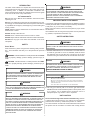
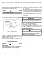
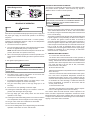
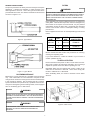
GAS-FIRED FURNACE
PACKAGED ROOFTOP SYSTEMS
MODELS PGB & PGC 090-180
USER’S INFORMATION MANUAL
WARNING
IF THE INFORMATION IN THESE INSTRUCTIONS IS
NOT FOLLOWED EXACTLY, A FIRE OR EXPLOSION
MAY RESULT CAUSING PROPERTY DAMAGE, PERSONAL INJURY OR LOSS OF LIFE.
–
TO PREVENT THE RISK OF PROPERTY DAMAGE, PERSONAL INJURY, OR
DEATH, DO NOT STORE
COMBUSTIBLE MATERIALS OR USE GASOLINE OR OTHER FLAMMABLE LIQUIDS OR VAPORS IN THE
®
VICINITY OF THIS APPLIANCE.
–
WHAT TO DO IF YOU SMELL GAS:
• DO NOT TRY TO LIGHT ANY APPLIANCE.
• DO NOT TOUCH ANY ELECTRICAL SWITCH; DO NOT USE ANY PHONE IN YOUR BUILDING.
• IMMEDIATELY CALL YOUR GAS SUPPLIER FROM A NEIGHBOR’S PHONE. FOLLOW THE GAS
US
C
SUPPLIER’S INSTRUCTIONS.
• IF YOU CANNOT REACH YOUR GAS SUPPLIER, CALL THE FIRE DEPARTMENT.
–
INSTALLATION AND SERVICE MUST BE PERFORMED BY A QUALIFIED INSTALLER, SERVICE AGENCY
ONLY INDIVIDUALS MEETING THE REQUIREMENTS OF AN "ENTRY LEVEL
OR THE GAS SUPPLIER.
TECHNICIAN" AS SPECIFIED BY THE AIR CONDITIONING AND REFRIGERATION INSTITUTE (ARI)
MAY USE THIS INFORMATION. ATTEMPTING TO INSTALL OR REPAIR THIS UNIT WITHOUT SUCH
BACKGROUND MAY RESULT IN PRODUCT DAMAGE, PERSONAL INJURY, OR DEATH.
Installer - Affix this manual, Installation Guide, and Warranty
adjacent to the appliance.
Owner - Read and keep all product literature in a safe place for
future reference.
W ARN ING
WARNING
SHUT OFF THE MANUAL GAS VALVE TO THE FURNACE BEFORE SHUTTING OFF
HIGH VOLTAGE!
DISCONNECT ALL POWER BEFORE INSTALLING OR SERVICING.
THE ELECTRICAL SUPPLY.
POWER SOURCES MAY BE PRESENT. FAILURE TO DO SO MAY CAUSE
SHOULD OVERHEATING OCCUR, OR THE GAS SUPPLY FAIL TO SHUT OFF,
MULTIPLE
PROPERTY DAMAGE, PERSONAL INJURY, OR DEATH.
WARNING
PRODUCT CONTAINS FIBERGLASS WOOL. DISTURBING THE INSULATION IN
WARNING
THIS PRODUCT DURING INSTALLATION, MAINTENANCE, OR REPAIR WILL
BREATHING THIS MAY CAUSE LUNG
CANCER. (FIBERGLASS WOOL IS KNOWN TO THE STATE OF CALIFORNIA TO
CAUSE CANCER.) FIBERGLASS WOOL MAY ALSO CAUSE RESPIRATORY, SKIN,
AND EYE IRRITATION. TO REDUCE EXPOSURE OR FOR FURTHER
EXPOSE YOU TO FIBERGLASS WOOL.
TO AVOID
PROPERTY DAMAGE, PERSONAL INJURY OR DEATH, DO NOT USE
THIS FURNACE IF ANY PART OF THE FURNACE HAS BEEN UNDER WATER.
IMMEDIATELY CALL A QUALIFIED SERVICE TECHNICIAN TO INSPECT THE
INFORMATION, CONSULT MATERIAL SAFETY DATA SHEETS AVAILABLE FROM
FURNACE AND TO REPLACE ANY PART OF THE CONTROL SYSTEM AND ANY
ADDRESS SHOWN BELOW.
GAS CONTROL HAVING BEEN UNDER WATER.
RECOGNIZE THIS SYMBOL AS A SAFETY PRECAUTION.
Due to policy of continual product improvement, the right is reserved
to change specifications and design
without notice.
Part No. HI-118
Printed in USA
©2005 Goodman Manufacturing Company, L.P.
Effective: November 2005
INTRODUCTION
WARNING
The intent of this bulletin is to acquaint the user with some of the
mechanical features and adjustments of the rooftop gas fired air
conditioning units. In addition, the information contained in this
manual is designed to identify any hazards and to serve as a guide
to the user in the event of any malfunctions.
FURNACE MUST NOT BE OPERATED IN
AN ATMOSPHERE CONTAMINATED
WITH HALOGENATED HYDROCARBON VAPORS, SOLVENT VAPORS OR ACID
VAPORS. EXPOSURE TO THESE ATMOSPHERES MAY CAUSE SEVERE DAMAGE
TO THE GAS FURNACE AND RESULT IN IMPROPER OR DANGEROUS
DO’S AND DO NOT’S
OPERATION. OPERATION OF THE GAS FURNACE IN SUCH A CONTAMINATED
ATMOSPHERE CONSTITUTES PRODUCT ABUSE.
DO read the User’s Manual and Installation Instructions before
operating the unit.
IMPORTANT NOTE TO THE OWNER
DO have your heating and cooling unit serviced at least once a year.
It is strongly recommended that the unit be inspected and serviced
by a qualified service agency at the beginning of each heating and
cooling season.
Your warranty certificate is supplied with the unit. Read the warranty
carefully and note what is covered. Keep the warranty certificate in
a safe place, so you can find it, if necessary.
Before using this manual, check the serial plate for proper model
identification.
NOTE: Additional periodic maintenance is recommended. Refer to
“Maintenance” section.
The installation and servicing of this equipment must be performed
by qualified, experienced technicians only.
DO NOT attempt to alter the unit.
DO NOT block or obstruct the furnace air inlets or outlets.
SAFETY INSTRUCTIONS
DO NOT tamper with the internal fan and limit control mechanisms.
DO NOT use any type of fuel other than indicated on the unit’s
nameplate.
WARNING
SAFETY
T HIS FURNACE
IS EQUIPPED WITH AN ELECTRIC IGNITION.
DO NOT
SIGNAL WORDS
ATTEMPT TO LIGHT THE FURNACE MANUALLY WITH A MATCH OR OTHER
Dear Homeowner, please recognize the following safety information. This information will alert you to the potential for personal
injury.
LIGHTING MEANS.
A. BEFORE OPERATING, it is recommended to use a leak detector
to check for gas leaks. If one is not available, smell all around
the appliance area for gas. Be sure to smell next to the floor
because some gas is heavier than air and will settle to the floor.
WARNING - Indicate hazards or unsafe practices which COULD
result in property damage, product damage, personal injury or
death.
WARNING
CAUTION - Indicate hazards or unsafe practices which MAY
result in in property damage, product damage, personal injury or
death.
AN UNDETECTED GAS LEAK WILL CREATE A DANGER OF EXPLOSION OR FIRE.
IF THE PRESENCE OF GAS IS SUSPECTED, FOLLOW THE INSTRUCTIONS ON
THE COVER OF THIS MANUAL. FAILURE TO DO SO COULD RESULT IN
SERIOUS PERSONAL INJURY OR DEATH.
WARNING
THIS PRODUCT CONTAINS OR PRODUCES A CHEMICAL OR
CHEMICALS WHICH
MAY CAUSE SERIOUS ILLNESS OR DEATH AND WHICH ARE KNOWN TO THE
WARNING
STATE OF CALIFORNIA TO CAUSE CANCER, BIRTH DEFECTS OR OTHER
–
REPRODUCTIVE HARM.
WARNING
WHAT TO DO IF YOU SMELL GAS:
• DO NOT TRY TO LIGHT ANY APPLIANCE.
• DO NOT TOUCH ANY ELECTRICAL SWITCH; DO NOT USE ANY PHONE IN YOUR BUILDING.
• IMMEDIATELY CALL YOUR GAS SUPPLIER FROM A NEIGHBOR’S PHONE. FOLLOW THE GAS
SUPPLIER’S INSTRUCTIONS.
• IF YOU CANNOT REACH YOUR GAS SUPPLIER, CALL THE FIRE DEPARTMENT.
TO AVOID POSSIBLE EQUIPMENT DAMAGE, PERSONAL INJURY, FIRE OR
DEATH, THE FOLLOWING INSTRUCTIONS MUST BE OBSERVED REGARDING UNIT
B. Use only your hand to push in or turn the gas control knob.
NEVER use tools. If the knob will not push in or turn by hand, don’t
try to repair it; call a qualified service technician. Force or
attempted repair may result in a fire or explosion.
LOCATION, AIR REQUIREMENTS AND OPERATING PROCEDURES.
WARNING
UNIT LOCATION
HEATING UNIT SHOULD NOT BE UTILIZED WITHOUT REASONABLE, ROUTINE,
INSPECTION, MAINTENANCE AND SUPERVISION. IF THE BUILIDNG IN WHICH ANY
These units are designed for outdoor installation only, either on
a slab just above ground level or on a rooftop. The unit should be
protected from access by unauthorized persons or children.
SUCH DEVICE IS LOCATED WILL BE VACANT, CARE SHOULD BE TAKEN THAT
SUCH DEVICE IS ROUTINELY INSPECTED, MAINTAINED AND MONITORED. IN THE
EVENT THAT THE BUILDING MAYBE EXPOSED TO FREEZING TEMPERATURES
At no time should an enclosure be constructed around the unit that
will prevent free air circulation or interfere with venting the flue
AND WILL BE VACANT, ALL WATER-BEARING PIPES SHOULD BE DRAINED, THE
BUILDING SHOULD BE PROPERLY WINTERIZED, AND THE WATER SOURCE
CLOSED. IN THE EVENT THAT THE BUILDING MAY BE EXPOSED TO FREEZING
TEMPERATURES AND WILL BE VACANT, ANY HYDRONIC COIL UNITS SHOULD
BE DRAINED AS WELL AND, IN SUCH CASE, ALTERNATIVE HEAT SOURCES
SHOULD BE UTILIZED.
2
discharge. An enclosure, overhang or obstruction shall not be
placed above the unit. Units installed next to a wall are likely to
experience backdrafts from adjacent walls.
5. Remove control access panel to expose gas control, if necessary.
6. Turn gas control switch or knob clockwise to “OFF”. NOTE: The
White-Rodgers valve cannot be turned to “OFF” unless the
knob is pushed in slightly at the black mark. Do not force.
The furnace requires air for combustion of the gas. Therefore, DO
NOT block or obstruct the air or vent openings to the furnace. Keep 7. Wait five (5) minutes to clear out any gas. If you then smell gas,
the area surrounding the furnace free from debris and snow. A vent
STOP! Follow step “A” in Safety Instructions. If you don’t smell
stack is not required, and must never be used.
gas, go to next step.
FURNACE AIR AND FLUE VENTING REQUIREMENTS
8. Turn gas control switch or knob counterclockwise to “ON”. The
knob has a safety latch to prevent accidental repositioning to
“ON”. The knob will hit a stop before it reaches “ON”. To continue
to turn the knob to “ON”: the Honeywell valve knob must be
pushed down or the White-Rodgers valve knob must be released to allow it to “POP-UP” then continue turning to “ON”.
CAUTION
DO NOT
INSTALL UNIT NEXT TO WINDOWS.
RECOMMENDED CLEARANCES
9. Replace control access panel. DO NOT omit any screws when
replacing panel.
As shown in Figure 1, a 36” clearance must be maintained on the
furnace access side of the unit. This clearance must be maintained
for accessibility and to allow proper combustion air and flue gas
flow. This clearance must be kept free of any combustible material.
WARNING
E XCEPT
DURING BRIEF PERIODS WHEN GAS PRESSURES ARE BEING
MEASURED BY QUALIFIED SERVICE PERSONNEL, THE FURNACE ACCESS
PANEL MUST BE IN PLACE AT ALL TIMES WHEN FURNACE IS
OPERATING.
10. Turn on all electric power to the appliance.
11. Set thermostat or controller to desired setting.
12. If the appliance will not operate, follow the instructions “To Turn
Off Gas To Appliance” and call your service technician or gas
supplier.
TO TURN OFF GAS TO APPLIANCE:
NOTE: UNIT FOOTPRINT IS 74 /16" x 74 /16"
9
9
W ARN ING
Figure 1. Service Clearances
HIGH VOLTAGE!
DISCONNECT ALL POWER BEFORE INSTALLING OR SERVICING.
MULTIPLE
It is recommended that a 75” clearance be maintained on the
POWER SOURCES MAY BE PRESENT. FAILURE TO DO SO MAY CAUSE
furnace access side of the unit to facilitate possible furnace or
PROPERTY DAMAGE, PERSONAL INJURY, OR DEATH.
blower shaft removal. It is recommended that at least 48”
clearance be maintained around the other three sides of the unit
to facilitate air circulation and to allow service access to the unit 1. Set the thermostat or controller to lowest setting or tun off power
at switch.
filters and mechanical components.
2.
Turn off all electrical power to the appliance if service is to be
These clearances are greater than those shown on the unit
performed.
dataplate, which are minimum clearances to combustible sur3. Remove control access panel.
faces for safety.
4. Turn gas control switch or knob clockwise until it stops at
marking. Push in slightly and turn clockwise to “OFF”.
OPERATING INSTRUCTIONS
5. Replace control access panel.
W ARN ING
HIGH VOLTAGE!
DISCONNECT ALL POWER BEFORE INSTALLING OR SERVICING.
MULTIPLE
POWER SOURCES MAY BE PRESENT. FAILURE TO DO SO MAY CAUSE
PROPERTY DAMAGE, PERSONAL INJURY, OR DEATH.
1. STOP! Read all safety information.
2. Set thermostat or heat control to lowest setting.
3. Turn off all electric power to the disconnect switch.
4. This appliance is equipped with an ignition device which
automatically lights the burners. DO NOT try to light by hand.
3
FAILURE OF THE FURNACE TO OPERATE
Honeywell Valve
White-Rodgers Valve
The furnace is provided with several safety control features which
can prevent furnace operation. These controls may require a
“RESET” action to resume normal operation.
Gas Valve
On/Off
Selector
Switch
INLET
OUTLET
OUTLET
INLET
CAUTION
FURNACE SAFETY CONTROLS THAT HAVE TRIPPED AND MUST BE MANUALLY
RESET INDICATES A HIGH PROBABILITY OF A DANGEROUS PROBLEM. IF THIS
Figure 2. Gas Valve
OCCURS, IT IS MANDATORY THAT THE FURNACE BE INSPECTED BY A
SEQUENCE OF OPERATION
QUALIFIED SERVICE CONTRACTOR.
1. IGNITION CONTROL
WARNING
Reset by turning the system switch on the room thermostat to
“OFF” and then back to “HEAT” or “AUTO”. This control can also
be reset by turning the thermostat setting down and then back
to the normal setting.
LINE VOLTAGE NOW PRESENT.
When the unit is provided with the proper electric power supply and
the proper gas supply, the furnace will operate in the following
sequence:
The ignition control will close the gas valve and terminate spark
if proof of ignition is not provided by the flame sensor within 4
to 7 seconds. The ignition control will allow 15 seconds of
ventor fan operation and then try another ignition sequence. If
the second ignition sequence fails, the ignition control will try
a third sequence and if that fails, the control will lockout for an
hour or must be reset as described above. Some of the
conditions that can cause ignition failure are loss of gas supply,
blockage of combustion air or flue passage, or malfunction
within the burner compartment.
With the room thermostat set at the “HEAT” or “AUTO” position,
increasing the temperature setting or a drop in room temperature
will signal the first stage of heat.
1. The furnace ventor fan operates.
2. The unit circulating air blower control begins timing and starts
the blow in approximately twenty to thirty seconds.
NOTE: If the fan switch on the thermostat panel is set to the “ON”
position, the blower will operate continuously.
2. TEMPERATURE LIMIT CONTROLS
3. After a 15 second pre-purge period of ventor fan operation, the
ignition spark is initiated and the gas valve is opened to the low
stage.
A. Furnace Limit: Automatic Reset.
The furnace limit control will terminate furnace operation if
the discharge air temperature exceeds the established limit
setting. The limit will reset and allow the furnace to resume
operation after a short off period. Some of the conditions that
can cause the limit to trip are low air flow, loose belts,
restricted ducts or dirty filters.
4. The ignition spark ignites the burner.
WARNING
T HIS FURNACE
IS EQUIPPED WITH AN ELECTRIC IGNITION.
B. Burner Roll-Out Limit:
DO NOT
ATTEMPT TO LIGHT THE FURNACE MANUALLY WITH A MATCH OR OTHER
Manual reset required at unit (located in burner compartment
above burners).
LIGHTING MEANS.
The burner roll-out limit control will terminate furnace operation if the burner compartment temperature exceeds the
established limit setting. Some of the conditions that can
cause the limit to trip are extremes in gas pressure, blockage
of combustion air or flue discharge, a malfunction within the
burner compartment or operation of the furnace with the
access panel removed.
5. The flame sensor confirms that ignition of the burner has
occurred and terminates the spark.
6. The furnace is now operating on low stage fire.
7. Increasing the thermostat setting or a further drop in room
temperature energizes the second heat stage.
8. The gas valve slowly opens to the high stage (15 to 30
seconds).
C. Reverse Airflow Limit:
9. The furnace is now operating at full heat output.
Automatic reset required at unit (located in blower compartment on side opposite blower motor and drive).
10. Lowering the thermostat setting or an increase in room temperature will de-energize the high stage.
The reverse airflow limit will terminate furnace operation if the
blower and filter compartment temperature exceeds the established limit setting. Some of the conditions that can cause the limit
to trip are loss of airflow from duct blockage, loss of drive belts or
tripping of the blower motor overloads.
11. The high stage gas valve slowly closes and the furnace
operates on low stage.
12. Lowering the thermostat setting further or a further increase in
room temperature will de-energize the low heating stage.
13. The gas valve closes and combustion is terminated.
14. The ventor fan is de-energized.
15. The unit circulating blow control begins timing and terminates
operation of the blower in 120 to 150 seconds.
4
W A R N IN G
HIGH VOLTAGE!
DISCONNECT ALL POWER BEFORE ATTEMPTING TO RESET
WARNING
CONTROLS. MULTIPLE POWER SOURCES MAY BE PRESENT. FAILURE TO DO
HIGH VOLTAGE!
THE FLAME SENSOR AND IGNITOR ELECTRODES CARRY VERY HIGH VOLTAGE.
DISCONNECT ALL POWER BEFORE SERVICING UNIT. MULTIPLE POWER
SO MAY CAUSE PROPERTY DAMAGE, PERSONAL INJURY, OR DEATH.
SOURCES MAY BE PRESENT. FAILURE TO DO SO MAY CAUSE PROPERTY
MANUAL LIMIT
DAMAGE, PERSONAL INJURY, OR DEATH.
FURNACE ACCESS PANEL
WARNING
E XCEPT
DURING BRIEF PERIODS WHEN GAS PRESSURES ARE BEING
MEASURED BY QUALIFIED SERVICE PERSONNEL, THE FURNACE ACCESS
PANEL MUST BE IN PLACE AT ALL TIMES WHEN FURNACE IS
OPERATING.
Always replace the screws that hold the door in place.
The access panel seals to the furnace ventor fan discharge by
engagement of the panel sleeve into the fan outlet sleeve. Be sure
that these sleeves are always in place and engaged to maintain
safe furnace operation.
Figure 4. Burner Assembly
BURNER FLAME REQUIREMENTS
The flame exits from the burner in a tubular shape and enters the
furnace heat exchanger. The flame should be blue in color and
should not lift away from the end of the burner. If the flame rolls out
rather than entering the heat exchanger, the heat exchanger, flue
passages and ventor assemblies may require inspection or
cleaning.
The carry over tube has a small flame approximately one half inch
long and operates continuously during burner operating. Refer to
“Maintenance” section in the installation instructions (IO-156) for
cleaning procedure.
Figure 3. Furnace Access Panel
BURNER ASSEMBLY
The burner assembly is removable for service or replacement of
the gas valve. The assembly consists of the following major parts
(See Figure 4):
A. Gas Valve
B. Gas Manifold
C. Gas Orifices
D. Burners
E. Carry Over Tube
F. Carry Over Orifice
G. Ignitor Electrode
H. Flame Sensor Electrode
I. Burner Support
The burner assembly must always be aligned and securely fastened in place with the upper and lower screws.
Figure 5. Burner Flame
5
FILTERS
PRIMARY AIR ADJUSTMENT
The primary air shutters are factory set and normally do not require
adjustment. If shutters are adjusted, no visible changes in the
flame appearance will occur. One of two types of burners will be
provided with the furnace. The shutters should be set and secured
as shown in Figure 6 or 7.
WARNING
TO AVOID PROPERTY DAMAGE, PERSONAL INJURY OR DEATH, DISCONNECT
ELECTRICAL POWER BEFORE REMOVING FILTERS. NEVER OPERATE FURNACE
WITHOUT A FILTER INSTALLED BECAUSE DUST AND LINT WILL BUILD UP ON
INTERNAL PARTS RESULTING IN LOSS OF EFFICIENCY, EQUIPMENT DAMAGE
AND POSSIBLE FIRE.
Every application may require a different frequency of replacement
of dirty filters. Filters must be inspected, cleaned or changed every
three months or as required. As a homeowner, it is your personal
responsibility to keep air filters clean. Remember that dirty filters
are the most common cause of inadequate heating or cooling
performance.
Filters supplied with the units are the disposable type and are as
follows:
Figure 6. Type l Burner
UNIT
SIZE
QTY.
FILTER
SIZE
PART NUMBER
(ONE FILTER)
090-102
3
25X25X2
B1369612
3
16X25X2
B1369610
3
20X25X2
B1369611
120-180
Become familiar with filter location and procedures for removing,
cleaning and replacing them.
If you need assistance, contact the installer of your furnace or
another qualified servicer.
TO REPLACE FILTERS
Remove the filter access panel on either or both sides of the unit.
See Figure 8. Filters are three deep and slide in and out. Always
replace the panels and screws before operating the unit.
Disposable filters must be replaced with a filter or filters of the
same size as that which is removed. Filters must comply with
UL900 or CAN/ULC-S111 Standards.
Figure 7. Type II Burner
When reinstalling filters, be careful to maintain correct airflow
direction.
ROUTINE MAINTENANCE
Maintenance is to be performed by a qualified service technician
only. User maintenance is to be restricted to frequent air filter
changes and to ensure the warnings and notices found elsewhere
in this manual be followed. We recommend that at a minimum
system maintenance be performed by a qualified service technician prior to the beginning of each heating season, and if equipped
with air conditioning prior to that season.
WARNING
PERSONAL INJURY OR DEATH MAY RESULT FROM IMPROPER MAINTENANCE
CALL YOUR INSTALLING DEALER
PERFORMED BY UNTRAINED PERSONNEL.
OR OTHER QUALIFIED SERVICE COMPANIES TO PERFORM THE MAINTENANCE
INSPECTION.
WARNING
Figure 8. Filter Access
TO AVOID PERSONAL INJURY OR DEATH DUE TO ELECTRICAL SHOCK,
DISCONNECT THE ELECTRICAL POWER BEFORE PERFORMING ANY
MAINTENANCE.
6
LUBRICATION
INSTRUCTIONS FOR PERIODIC INSPECTION OF THE
To lubricate the ventor motor, remove the furnace access panel. FURNACE
Lubricate the motor in two locations as shown in Figure 9. Use SAE
20W lubricant and add five drops to each location. The motor
WARNING
should be lubricated at the beginning of each heating season. DO
NOT OVER LUBRICATE.
IMPROPER INSTALLATION, ADJUSTMENT, ALTERATION, SERVICING OR
MAINTENANCE CAN CAUSE PROPERTY DAMAGE, PERSONAL INJURY OR DEATH.
WARNING
DO NOT DRIP OIL
ANNUAL INSPECTION
The furnace should be inspected by a qualified installer, or service
agency at least once per year. This check should be performed at
the beginning of the heating season and periodically during the
season. This will insure that all furnace components are in proper
working order and that the heating system functions appropriately.
Particular attention should be paid to the following items. Repair
as necessary.
ON THE GAS VALVE. THE OIL MAY DAMAGE THE
NON-METALLIC PARTS AND RENDER THE VALVE INOPERABLE. REMOVE ANY
OIL RESIDUES FROM THE BURNER COMPARTMENT.
• The physical support of the furnace should be sound without
sagging, cracks, gasp, etc., around the base to provide a seal
between the support and the base.
• Flue pipe system. Check for blockage and/or leakage. Check
the outside termination and the connections at and internal to
the furnace.
• The return air duct connection should be physically sound and
sealed to the furnace casing.
• Burners. Check for proper ignition, burner flame, and flame
sense. Flames should extend directly outward from burners
without curling, floating or lifting off.
• Wiring. Check electrical connections for tightness and/or corrosion. Check wires for damage.
• Filters. Check that filters are clean and in the proper placement in the furnace or duct system.
Figure 9. Ventor Motor
• Remove the furnace access panel and visually inspect the
burner area and vent fan outlet for corrosion, corrosion particles, or soot. There should be no obvious signs of deterioation
of the furnace. If any evidence of deterioration is observed,
contact a qualified service agency.
NOTE: Information regarding the inspection and cleaning of the
burners and flue gas passagemways is included in the “Maintenance” section of the Installation Instructions (IO-156).
7
SAFETY LABELS
FOR YOUR SAFETY READ BEFORE OPERATING
WARNING
A. This appliance does not have a pilot. It
is equipped with an ignition device which
automatically lights the burners. Do not
try to light the burners by hand.
B. BEFORE OPERATING smell around
the appliance area for gas. Be sure to
smell next to the floor because some gas
is heavier than air and will settle on the
floor.
WHAT TO DO IF YOU SMELL GAS
Do not try to light any appliance.
Do not touch any electric switch;
do not use any telephone in your
building.
Immediately call your supplier
from a neighbor's phone. Follow
the gas suppliers instructions.
If you do not follow these instructions exactly,
a fire or explosion may result causing property
damage, personal injury or loss of life.
If you cannot reach your gas supplier,
call the fire department.
C. Use only your hand to move the gas
control switch or knob. Never use
tools. If the gas control switch or knob
will not operate, don't try to repair it,
call a qualified service technician.
Force or attempted repair may result in
a fire or explosion.
D. Do not use this appliance if any part
has been under water. Immediately call
a qualified service technician to inspect
the appliance and to replace any part of
the control system and any gas control
which has been under water.
WARNING: Improper
installation, adjustment,
alteration, service or
maintenance can
cause injury or
property damage.
Refer to the user's
information manual
provided with this
furnace. For assistance
or additional information
consult a qualified
installer, service agency
or the gas supplier.
This furnace must be
installed in accordance
with the manufacturers
instructions and local
codes. In the absence
of local codes, follow
the National Fuel Gas
Code, ANSI Z223.1.
OPERATING INSTRUCTIONS
1. STOP! Read the safety information
above on this label.
2. Set the thermostat to lowest setting.
3. Turn off all electric power to the
appliance.
4. This appliance is equipped with an
automatic ignition system which
automatically lights the burners. Do not
try to light the burners by hand.
5. Remove control access panel.
6. Move the gas control switch or knob
to "OFF".
GAS CONTROL
SWITCH SHOWN
IN "ON" POSITION
7. Wait five (5) minutes to clear out any
gas. If you then smell gas, STOP!
Follow "B" in the safety information
above on this label. If you don't smell
gas, go to the next step.
8. Move the gas control switch or knob
to "ON".
9. Replace control access panel.
10. Turn on all electric power to the
appliance.
11. Set the thermostat to the desired
setting.
12. If the appliance will not operate,
follow the instructions "To Turn Off Gas
To Appliance" and call your service
technician or gas supplier.
KNOB
ON
OFF
GAS CONTROL
GAS CONTROL
SWITCH SHOWN
IN "ON" POSITION
TO TURN OFF GAS TO APPLIANCE
1. Set the thermostat to its lowest setting.
2. Turn off all electric power to the
appliance if service is to be performed.
3. Remove control access panel.
For outdoor
installation only.
4. Move the gas control switch or knob
to "OFF". Do not force.
5. Replace control access panel.
WARNING: If not
installed, operated
and maintained in
accordance with the
manufacturer's
instructions, this
product could expose
you to substances
in fuel combustion
which can cause
death or serious
illness and which
are known to the
State of California to
cause cancer, birth
defects or other
reproductive harm.
This product contains
fiberglass insulation.
Fiberglass insulation
contains a chemical
known by the State of
California to cause
cancer.
FOR YOUR SAFETY
Do not store or use gasoline or
other flammable vapors and liquids in the vicinity of this
or any other appliance.
B14933-247
CONSUMER INFORMATION LINE TOLL FREE
1-877-254-4729 (U.S. only)
email us at: [email protected]
fax us at: (731) 856-1821
For convenience, record the Model, Manufacturing Number and
Serial Number of the unit found on the nameplate of the furnace
MODEL NUMBER: _ _ _ _ _ _ _ _ _ _ _
(Not a technical assistance line for dealers.)
MANUFACTURING NUMBER: _ _ _ _ _ _ _ _
Outside the U.S., call 1-713-861-2500.
(Not a technical assistance line for dealers.)
Your telephone company will bill you for the call.
©2005 Goodman Manufacturing Company, L.P.
SERIAL NUMBER: _ _ _ _ _ _ _ _ _ _
8
November 2005