1
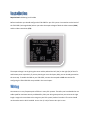
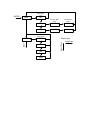
Team BlackSheep CORE
The all-in-one FPV solution from the sheep that fly
The TBS CORE is a progression of the revolutionary TBS Power Supply Unit. We have listened to
customer’s requests and made the TBS CORE compatible with 5V & 12V cameras and 5V & 12V video
transmitters up to 1W emitted power. The TBS CORE supports all battery sizes between 2 and 10 cells.
We have also built in an optional OSD. Why? Because we can!
Contents
The all-in-one FPV solution from the sheep that fly ................................................................................. 1
Installation .................................................................................................................................................... 2
Wiring ........................................................................................................................................................ 2
Current sensor .......................................................................................................................................... 4
Backup power ........................................................................................................................................... 5
RF Noise .................................................................................................................................................... 5
The TBS CORE OSD ........................................................................................................................................ 5
Enable / disable ......................................................................................................................................... 6
Functionality ............................................................................................................................................. 6
Voltage Sensors ..................................................................................................................................... 6
Current Consumption ........................................................................................................................... 6
Relative Signal Strength Indicator (RSSI) ............................................................................................... 6
Configuration ............................................................................................................................................ 7
Installation
Required tools: Soldering iron & solder
Before installation you should configure the TBS CORE for your FPV system. You need to see the back of
the TBS CORE (see image below) where you select the output voltage of both the video camera (CAM)
and the video transmitter (VTX).
The output voltage is set by joining the center solder pad and the left (12V) or the right (5V) of the VTx
and Camera ports respectively. If you are planning to use a third-party OSD, you can already proceed to
the next step. To enable the OSD on your TBS CORE, connect the two pads at OSD. Instructions for
configuring the TBS CORE OSD are provided in the next chapter.
Wiring
Connectors are a very frequent point of failure in many FPV systems. Therefore, we have decided to use
solder-pads for maximum security and durability. Plan your wiring setup and cut your wires to the right
length. Longer wires translate to less range on your FPV system, but don’t overdo it! The wires should
not be under tension while installed. Leave ~2cm (1 inch) of excess wire just in case.
Once the wires to your camera and video transmitter are cut to length, refer to the rear of the TBS CORE
(picture above) to plan how you want to solder the wires. Expose their strands, twist them thoroughly
and apply solder. Try to minimize the amount of time you heat the wires and solder, as it makes your
cables more susceptible to fatigue later on! Now cut the exposed strands to length.
On the TBS CORE, pre-tin the solder pads with a bit of solder. Verify once again that the pinout is
correct, position the wire above the pre-tinned pad and apply heat to the solder pad on the TBS CORE.
Repeat for all cables that you want to connect, and you’re done. To save space and make life easier, you
can solder at both the front and the back.
Current sensor
The TBS CORE can be purchased with an optional current sensor. The main power input of the TBS CORE
doubles as current sensor port. If no current sensor is connected, the TBS CORE OSD can still measure
voltage on both power inputs, but not current.
The current sensors come in two flavors, 50A and 100A. The 50A is more accurate at lower voltages.
Wire the current sensor between your battery plug and ESC. Please be careful to install it in the right
direction, copy below image carefully. When pulling a lot of power, spread some solder to fill up the
holes.
Backup power
The TBS CORE provides the possibility to connect a fully-redundant secondary battery to power your FPV
system (optional!). In case your main battery fails, the backup takes over and keeps the FPV system
running long enough for you to (hopefully) locate your plane. The backup power port (VIN2) is selected
when the voltage of the main battery port is lower and vice versa. It is therefore recommended to
connect a backup-battery with fewer cells than your main battery (e.g. 3S main battery and 2S backup
battery).
RF Noise
Video transmitters are very sensitive to noise from onboard electronics such as servos, electronic speed
controllers (ESC) and LED drivers. The TBS CORE filters EMI and other sources of interference and
protects your sensitive FPV electronics and increases your video range.
Installing the TBS CORE requires some planning. Please keep adequate separation between TBS CORE
and your R/C receiver. The TBS CORE includes two very powerful switching-regulators which can
interfere with your UHF receiver when placed in close proximity. This is not something that is unique to
the TBS CORE but rather to all devices with switching regulators. The noise decreases exponentially with
distance, so every centimeter or inch helps get more range out of your system. How drastic is the range
decrease? A UHF R/C system can fly to about 15km (about 10 miles) with the TBS CORE sitting in close
proximity (small quadrocopter frame).
The TBS CORE OSD
In FPV, simple is better. Wire clutter from many different devices all connected together creates a
sophisticated conglomeration of ground-loops and “antennas” that can have significant impact on the
reliability of your FPV system and your FPV experience. For this reason, TBS has put the bare essentials
that every FPV pilot needs – voltage, current and relative signal strength indicator (RSSI) – in an OSD that
sits right on the TBS CORE. There is no simpler way to set up your FPV system! You can disable the OSD
with a solder-jumper and use any of your third party OSDs.
Enable / disable
To enable the OSD, connect the two solder pads (OSD solder pad). To disable the OSD, remove the
solder. Removing the solder is easy. Heat it with an iron and then GENTLY hit the OSD against a hard
surface. The heated, liquid solder will just peel off. Obviously there are better ways using solder wick,
but we’re lazy like that!
Functionality
The OSD includes only the bare essentials that an FPV pilot needs. There is no GPS support planned, we
want to keep it as simple and unobtrusive as possible.
Voltage Sensors
The primary and the secondary power input are both monitored by the OSD. When a battery is
connected to the port, the voltage is shown. The voltage sensor on the primary output also works if you
have a current sensor.
Current Consumption
If you connect a TBS current sensor to the OSD, the current consumption is automatically displayed. All
current sensors are pre-calibrated and work out of the box with the OSD, but the OSD needs to know
what model you have connected. The readings are not accurate otherwise! Please read the OSD
configuration chapter to find out how you can configure the OSD.
Relative Signal Strength Indicator (RSSI)
RSSI is the signal strength of your R/C signal that arrives at the plane. All major FPV R/C system vendors
support either analog or digital (PWM) RSSI. The TBS OSD has a RSSI port where you can connect and
then calibrate the RSSI output. RSSI is shown with a percentage number ranging from 0 to 100. If it is
calibrated correctly, 0% means no signal, 100% means full signal. Connecting RSSI is straight forward.
Simply wire the RSSI output of your receiver to the appropriate port on the TBS CORE.
Refer to the manual of your R/C system to find out where the RSSI comes from. Configuration
instructions of analog RSSI are available in the next chapter.
The EzUHF is the first FPV UHF system that supports digital RSSI. To feed that information to the TBS
CORE, connect your EzUHF receiver to the ImmersionRC Tools and select a channel on the “RSSI Needle”
setting. That channel needs to be routed to the RSSI input. For configuration instructions please refer to
the next chapter.
Configuration
Configuring the TBS CORE OSD is incredibly simple. Power up your FPV system and enable the OSD. Now
press the configuration button (see figure 3) for multiple seconds until you enter the OSD menu.
To enter a menu or confirm a value, keep the button pressed for multiple seconds. To jump to the next
option press the button for a short time. Here is a use diagram for the TBS CORE OSD:
RSSI
OFF
Set RSSI Max
Value
Set RSSI Min
Value
ANA
MAX
MIN
DIG
MAX
MIN
Select Current
Sensor Type
OFF
25A
50A
100A
Botton input
Short Push
CURR.
EXIT
ENTER
Select RSSI
Type
Long Push